Y-TYPE SHOP MANUAL - My Generatormygenerator.com.au/media/SHT25D-ENGEL-Manual.pdf · sawafuji...
28
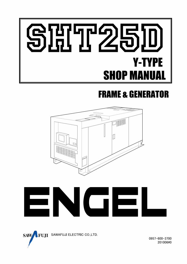
SAWAFUJI ELECTRIC CO.,LTD. 0957-600-3700 201006#0 FRAME & GENERATOR SHOP MANUAL Y-TYPE
Transcript of Y-TYPE SHOP MANUAL - My Generatormygenerator.com.au/media/SHT25D-ENGEL-Manual.pdf · sawafuji...
SAWAFUJI ELECTRIC CO.,LTD.0957-600-3700
201006#0
FRAME & GENERATOR
SHOP MANUAL
Y-TYPE
CONTENTS SHT25D-Y
1. SPECIFICATIONS
1-1. SPECIFICATIONS ………………………………………………………………………………………….2
1-2. PERFORMANCES ……………………………………………………………………………………….3
1-3. DIMENSIONAL DRAWINGS ……………………………………………………………………………………..4
1-4. WIRING DIAGRAM …………………………………………………………………………………………5
2. SERVICE INFORMATIONS
2-1. SAFETY PRECAUTIONS ………………………………………………………………………………6
2-2. ELECTRICAL PRECAUTIONS ……………………………………………………………………….6
2-3. MAINTENANCE STANDARDS
2-3-1. GENERATOR RESISTANCE …………………………………………………………………………7
2-3-2. ENGINE ……………………………………………………………………………………..8-10
2-3-3. TIGHTENING TORQUES ………………………………………………………………………………….11
2-4. AVR ……………………………………………………………………………………………….12
2-5. CHANGE OG FREQUENCY ………………………………………………………………………………….13
3. TROUBLESHOOTING
3-1. GENERATOR
3-1-1. EVIDENT PHYSICAL DEFECTS ……………………………………………………………………………….14
3-1-2. VOLTAGE FAULTS ……………………………………………………………………………..15
3-1-3. ENGINE CIRCUIT TROUBLESHOOTING …………………………………………………………16-18
3-2. ENGINE ………………………………………………………………………………………..19-21
4. DISASSEMBLY AND SERVICING
4-1. EXTERNAL COMPONENT …………………………………………………………………………22
4-2. GENERATOR …………………………………………………………………………………….23
4-3. SERVICING ……………………………………………………………………………..24-27
- 1 -- 1 -- 1 -- 1 -

1. SPECIFICATIONS SHT25D-Y
1-1. SPECIFICATIONS
YFrequency 50 Hz
Output 20 kVA (16kW)
Voltage 415 V
Amps 27.8 A
Power factor
Type
No. of phase
No. of poles
Voltage reg. system
Insulation class
Coupling
Model
Design
No. of sylinders
Bore × Stroke
Displacement
JIS D0006 21.2(28.8) kW(PS)/1500 rpm
JIS D8014 18.4(25.0) kW(PS)/1500 rpm
Governor regulation
Combustion system
Fuel injection pump
Governor
Nozzle
Injection timing
Injection pressure
Compression ratio
Lubricating system
Lubricating filter
Lubricating oil
Lubricating oil capacity
Fuel oil
Fuel tank capacity
Cooling system
Coolant capacity
Fan type
Flywheel type
Flywheel housing type
Starting system
Starting support device
Dynamo for charging
Direction of rotation
Battery (V ×Ah/5Hr)
Volt meter
Ampere meter
Frequency meter
Hour meter
Warning lights
Output
ATS terminal
Terminal
Weight (dry)
Yes
No
Yes
Indicator lights (4-conditions)
Yes
Yes
Accessary
545 kg
- 2 -- 2 -- 2 -- 2 -
Continuous output
87 × 92.4 mm
2,197 cc
SAE No.4
Less than 5 %
Spherical type (New T.V.C.S : Three Voltex Combustion system)
Bosch "Mini" type
Mechanical governer
SHT25D
0.8
Three
Generator
Engine
Rated
Rated output
Rotating-field, brush-less, self-excitation system, AC generator
4
AVR
H
Coupling disc;SAE#7.5(offset disc) Flange adaptor;SAE#4
V2203-B-BGSE-1
Vertical, liquid,cooled, 4-cycle, diesel engine
4
Bosch "Throttle" type
0.30 to 0.33 rad. (17 to 19°) before T.D.C.
13.73 Mpa, 140 kgf/cm2, 1991 psi
23 : 1
Pusher type
SAE No.7-1/2
Forced lubricating by trochoid pump
Cartridge type (full flow paper filter)
Quality better than CD class
7.6 L
Diesel fuel No.2-D (ASTMD975)
72 L
Water cooling with water pump
8.1 L
Electric starting with starter (12 V, 1.4 kw)
By glow plug in combustion chamber
Counterclockwise (from flywheel side)
80D26R (12V-55Ah)
12 V , 480 w
SHT25D-Y
1-2. PERFORMANCES
Transient %
Stedy %
Recovery time sec
Voltage stability %
Transient %
Stedy %
Recovery time sec
Frequency stability %
Insulation resistance Mohm
Wave-form distortion %
Circuit protector capacity A
Insulation class ---
Fuel consumption (full load) lit./h
Continuous operable hours (3/4 load) h
Fuel tank capacity lit.
Sound level (7m) dB(A)
- 3 -- 3 -- 3 -- 3 -
ModelSHT25D
less than 30
less than +/-2.5
less than 5
less than +/-1
less than 10
less than 7
less than 8
Voltage
regulation
Frequency
regulation
less than +/-0.5
more than 10
66
H
72
Y
less than 5
29
less than 5.8
more than 17.6

SHT25D-Y
1-3. DIMENSIONAL DRAWINGS
- 4 -- 4 -- 4 -- 4 -
1660mm690mm
900mm
SHT25D-Y
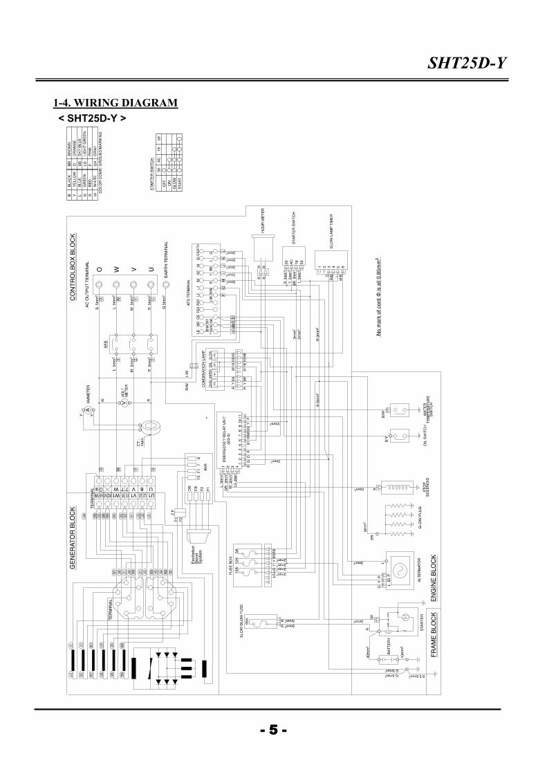
1-4. WIRING DIAGRAM
- 5 -- 5 -- 5 -- 5 -
< SHT25D-Y >

2. SERVICE INFORMATION SHT25D-Y
2-1. SAFETY PRECAUTIONS
•Read the instructions before you begin, and be sure you have the tools and skills
required to perform the tasks safely.
•Be sure that the engine is off before you begin any maintenance or repairs.
This will reduce the possibility of several hazards:
Carbon monoxide poisoning from engine exhaust. Be sure there is adequate ventilation whenever you run the engine.
Burns from hot parts. Let the engine cool before you touch it.
Injury from moving parts. Do not run the engine unless the instruction tells you to do so. Even then, keep your
hands, fingers, and clothing away.
•To reduce the possibility of a fire or explosion, be sure when working around fuel.
Use only a nonflammable solvent, not fuel, to clean parts.
Keep all cigarettes, sparks, and flames away from all fuel-related parts.
2-2. ELECTRIC PRECAUTIONS
1) Check the connector terminals for bend, excessive extrusion, missing terminal,
or other abnormalities before connecting the connector.
2) To connect, insert the connector as full as it goes.
3) Check the connector cover for breakage and check whether the connector
female terminal is not open excessively. Then, connect the connector securely.
4) Clamp the wire harnesses securely so that they do not interfere with the rotating
parts, moving parts and the hot parts.
5) Route and connect the wire harnesses properly. Be sure that the harnesses are
not slack, twisted or pulled taut.
6) Take care not to pinch the wire harnesses during installation of a part.
7) Read the tester manufacturer's operation instructions carefully before operation
with a tester.
- 6 -- 6 -- 6 -- 6 -
SHT25D-Y
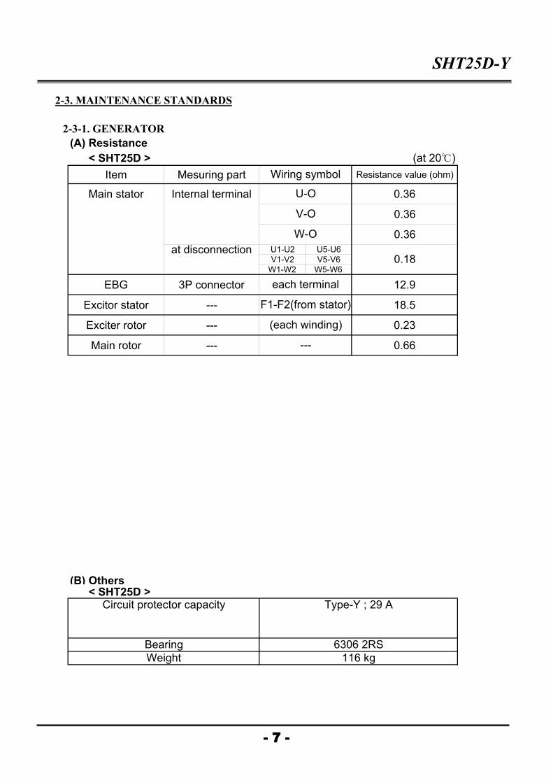
2-3. MAINTENANCE STANDARDS
2-3-1. GENERATOR
(A) Resistance
< SHT25D > (at 20℃)
Item Mesuring part Resistance value (ohm)
Main stator Internal terminal 0.36
0.36
0.36
at disconnection U1-U2 U5-U6
V1-V2 V5-V6
W1-W2 W5-W6
EBG 3P connector 12.9
Excitor stator --- 18.5
Exciter rotor --- 0.23
Main rotor --- 0.66
(B) Others < SHT25D >
0.18
---
Wiring symbol
(each winding)
each terminal
F1-F2(from stator)
U-O
V-O
W-O
- 7 -- 7 -- 7 -- 7 -
Circuit protector capacity
Bearing
Weight
Type-Y ; 29 A
6306 2RS
116 kg

SHT25D-Y
2-3-2. ENGINE
(A) Engine Body
Factory specification Allowable limit
Cylinder head surface flatness - 0.05 mm
Top clearance 0.55 - 0.70 mm -
Thickness of gasket free 1.30 - 1.40 mm -
tightened 1.15 - 1.25 mm -
Compression pressure 3.53 - 3.72 Mpa -
36 - 38 kgf/cm2
Variance among cylinders - 10% or less
Valve clearance (cold) 0.18 - 0.22 mm -
Valve seat width (In/Ex) 2.12 mm -
Valve seat angle (In) 1.047 rad. (60°) -
angle (Ex) 0.785 rad. (45°) -
Valve face angle (In) 1.047 rad. (60°) -
angle (Ex) 0.785 rad. (45°) -
Valve recessing protrusion 0.05 mm
recess 0.15 mm
Valve stem to Valve guide clearance 0.040 - 0.070 mm -
Valve stem O.D. 7.960 - 7.975 mm -
Valve guide I.D. 8.015 - 8.030 mm -
Valve timing (Intake valve) open 0.21 rad. (12°) -
before T.D.C.
close 0.63 rad. (36°) -
after B.D.C.
Valve timing (Exhaust valve) open 1.05 rad. (60°) -
before T.D.C. -
close 0.21 rad. (12°) -
after B.D.C.
Valve spring free length 41.7 - 42.2 mm 41.2 mm
setting load 117.6 N 100.0 N
12.0 kgf 10.2 kgf
setting length 35.0 mm 35.0 mm
tilt - 1.0 mm
Rocker arm shaft to Rocker arm clearance 0.016 - 0.045 mm 0.15 mm
Rocker arm shaft O.D. 13.973 - 13.984 mm -
Rocker arm I.D. 14.000 - 14.018 mm -
Tappet to Tappet guide bore clearance 0.020 - 0.062 mm 0.07 mm
Tappet to Tappet guide bore O.D. 23.959 - 23.980 mm -
Tappet guide bore I.D. 24.000 - 24.021 mm -
Camshaft side clearance 0.07 - 0.22 mm 0.3 mm
Camshaft aligment - 0.01 mm
Cam henght In/Ex 33.47 mm 33.42 mm
Camshaft journal to Cylinder block bore oil clearance 0.050 - 0.091 mm 0.15 mm
Camshaft journal O.D. 39.934 - 39.950 mm -
Camshaft bearing I.D. 40.000 - 40.025 mm -
0.4 mm
- 8 -- 8 -- 8 -- 8 -
Item

SHT25D-Y
(A) Engine Body (continued)
Factory specification Allowable limit
Timing gear
Crank shat to Idle gear backlash 0.0415 - 0.1122 mm 0.15 mm
Idle gear to Cam gear backlash 0.0415 - 0.1154 mm 0.15 mm
Idle gear to Injection pump gear backlash 0.0415 - 0.1154 mm 0.15 mm
Crank gear to Oil pump drive gear backlash 0.0415 - 0.1090 mm 0.15 mm
Idle gear side clearance 0.20 - 0.51 mm 0.9 mm
Idle gear shaft to Idle gear bushing clearance 0.021 - 0.079 mm 0.10 mm
Idle gear bushing I.D. 28.000 - 28.021 mm -
Idle gear shaft O.D. 27.967 - 27.980 mm -
Piston pin bore I.D. 25.000 - 25.013 mm 25.05 mm
Piston pin clearance second ring 0.093 - 0.120 mm 0.20 mm
oil ring 0.020 - 0.052 mm 0.15 mm
Ring gap top ring 0.30 - 0.45 mm 1.25 mm
second ring 0.30 - 0.45 mm 1.25 mm
oil ring 0.25 - 0.45 mm 1.25 mm
Connecting rod aligment - 0.05 mm
Piston pin to Small end bushing clearance 0.014 - 0.038 mm 0.15 mm
Piston pin O.D. 25.002 - 25.011 mm -
Small end bushing I.D. 25.025 - 25.040 mm -
Crankshaft aligment - 0.02 mm
Crankshaft journal to Crankshaft bearing 1 oil clearance 0.04 - 0.118 mm 0.2 mm
Crankshaft journal O.D. 51.921 - 51.940 mm -
Crankshaft bearing 1 I.D. 51.980 - 52.025 mm -
Crankshaft journal to Crankshaft bearing 2 oil clearance 0.04 - 0.104 mm 0.2 mm
Crankshaft journal O.D. 51.921 - 51.940 mm -
Crankshaft bearing 2 I.D. 51.980 - 52.025 mm -
Crank pin to Crankpin bearing oil clearance 0.025 - 0.087 mm 0.2 mm
Crank pin O.D. 46.959 - 46.975 mm -
Crankpin bearing I.D. 47.000 - 47.046 mm -
Crankshaft clearance 0.15 - 0.31 mm 0.5 mm
Cylinder bore I.D. 87.000 - 87.022 mm +0.15 mm
Oversized cylinder liner I.D. +0.5 mm +0.15 mm
Item
- 9 -- 9 -- 9 -- 9 -

SHT25D-Y
(B) Lubricating System
Factory specification Allowable limit
Engine oil pressure at idle speed 98 kPa 49 kPa
1.0 kgf/cm2 0.5 kgf/cm2
at rated speed 294.2 - 441 kPa 245 kPa
3.0 - 4.5 kgf/cm2 2.5 kgf/cm2
Inner rotor to Outer rotor clearance 0.03 - 0.14 mm -
Outer rotor to Pump body clearance 0.11 - 0.19 mm -
Inner rotor to Cover end clearance 0.105 - 0.150 mm -
(C) Cooling Syatem
Thermostat's valve opening temperature 69.5 - 72.5 ℃ -
Temperature at whitch thermostat completelt opens 85 ℃ -
Radiator water tightness water tightness at -
specified pressure
137 kPa (1.4 kgf/cm2) -
Radiator cap air leakage pressure 10 seconds or more -
falling time 0.988 → 59 kPan2 -
0.6 → 0.9 kgf/cm2 -
Fan belt tension 10 - 12 mm/10kgf -
(D) Fuel System
Injection pump injection timing 0.30 - 0.33 rad. -
(17 - 19 °)
before T.D.C.
Pump element fuel tightness - 14.7 Mpa
150 kgf/cm2
Delivery valve fuel tightness more 10 seconds 5 seconds
14.7 → 13.7 Mpa 14.7 → 13.7 Mpa
150 → 140 kgf/cm2 150 → 140 kgf/cm2
Fuell injection nozzle injection 13.73 → 14.71 Mpa -
pressure 140 → 150 kgf/cm2
Fuell injection nozzle valve seat fuel tightness when the pressure is -
12.75 Mpa (130 kgf/cm2),
the valve seat must be
fuel tightness.
(E) Electrical System
Starter / Commutator O.D. 30.0 mm 29.0 mm
Starter / Mica undercut 0.5 - 0.8 mm 0.2 mm
Starter / Brush length 15.0 mm 10.0 mm
Alternator / Output current 14 V, 35 A/4000rpm -
Alternator / Rotor coil resistance 4 ohm -
Alternator / Slip ring O.D. 32.5 mm 32.1 mm
Alternator / Brush length 12.5 mm 5.5 mm
Glow plug / Resistance 0.8 ohm -
- 10 -- 10 -- 10 -- 10 -
Item
SHT25D-Y
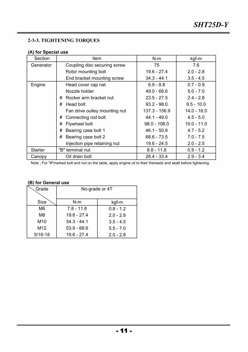
2-3-3. TIGHTENING TORQUES
(A) for Special use
N-m kgf-m
Generator Coupling disc securing screw 75 7.6
Rotor mounting bolt 19.6 - 27.4 2.0 - 2.8
End bracket mounting screw 34.3 - 44.1 3.5 - 4.5
Engine Head cover cap nat 6.9 - 8.8 0.7 - 0.9
Nozzle holder 49.0 - 68.6 5.0 - 7.0
# Rocker arm bracket nut 23.5 - 27.5 2.4 - 2.8
# Head bolt 93.2 - 98.0 9.5 - 10.0
Fan drive oulley mounting nut 137.3 - 156.9 14.0 - 16.0
# Connecting rod bolt 44.1 - 49.0 4.5 - 5.0
# Flywheel bolt 98.0 - 108.0 10.0 - 11.0
# Bearing case bolt 1 46.1 - 50.9 4.7 - 5.2
# Bearing case bolt 2 68.6 - 73.5 7.0 - 7.5
Injection pipe retaining nut 19.6 - 24.5 2.0 - 2.5
Starter "B" terminal nut 8.8 - 11.8 0.9 - 1.2
Canopy Oil drain bolt 28.4 - 33.4 2.9 - 3.4
Note ; For "#"marked bolt and nut on the table, apply engine oil to their thereads and seatt before tightening.
(B) for General use
kgf-m
0.8 - 1.2
2.0 - 2.8
3.5 - 4.5
5.5 - 7.0
2.0 - 2.8
- 11 -- 11 -- 11 -- 11 -
Section Item
No-grade or 4T
N-m
M6
M8
M10
M12
Size
Grade
5/16-18
7.8 - 11.8
19.6 - 27.4
34.3 - 44.1
53.9 - 68.6
19.6 - 27.4
SHT25D-Y
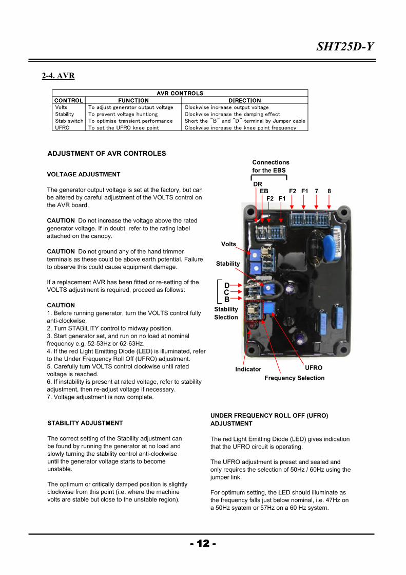
2-4. AVR
ADJUSTMENT OF AVR CONTROLES
- 12 -- 12 -- 12 -- 12 -
VOLTAGE ADJUSTMENT
The generator output voltage is set at the factory, but can
be altered by careful adjustment of the VOLTS control on
the AVR board.
CAUTION Do not increase the voltage above the rated
generator voltage. If in doubt, refer to the rating label
attached on the canopy.
CAUTION Do not ground any of the hand trimmer
terminals as these could be above earth potential. Failure
to observe this could cause equipment damage.
If a replacement AVR has been fitted or re-setting of the
VOLTS adjustment is required, proceed as follows:
CAUTION
1. Before running generator, turn the VOLTS control fully
anti-clockwise.
2. Turn STABILITY control to midway position.
3. Start generator set, and run on no load at nominal
frequency e.g. 52-53Hz or 62-63Hz.
4. If the red Light Emitting Diode (LED) is illuminated, refer
to the Under Frequency Roll Off (UFRO) adjustment.
5. Carefully turn VOLTS control clockwise until rated
voltage is reached.
6. If instability is present at rated voltage, refer to stability
adjustment, then re-adjust voltage if necessary.
7. Voltage adjustment is now complete.
STABILITY ADJUSTMENT
The correct setting of the Stability adjustment can
be found by running the generator at no load and
slowly turning the stability control anti-clockwise
until the generator voltage starts to become
unstable.
The optimum or critically damped position is slightly
clockwise from this point (i.e. where the machine
volts are stable but close to the unstable region).
UNDER FREQUENCY ROLL OFF (UFRO)
ADJUSTMENT
The red Light Emitting Diode (LED) gives indication
that the UFRO circuit is operating.
The UFRO adjustment is preset and sealed and
only requires the selection of 50Hz / 60Hz using the
jumper link.
For optimum setting, the LED should illuminate as
the frequency falls just below nominal, i.e. 47Hz on
a 50Hz syatem or 57Hz on a 60 Hz system.
CONTROLCONTROLCONTROLCONTROL FUNCTIONFUNCTIONFUNCTIONFUNCTION DIRECTIONDIRECTIONDIRECTIONDIRECTION Volts To adjust generator output voltage Clockwise increase output voltage Stability To prevent voltage huntiong Clockwise increase the damping effect Stab switch To optimise transient performance Short the "B" and "D" terminal by Jumper cable UFRO To set the UFRO knee point Clockwise increase the knee point frequency
AVR CONTROLSAVR CONTROLSAVR CONTROLSAVR CONTROLS
Frequency Selection
UFRO
Stability
Slection
Indicator
B
DC
DREB
F2 F1
F2 F1 7 8
Volts
Stability
Connections
for the EBS
SHT25D-Y
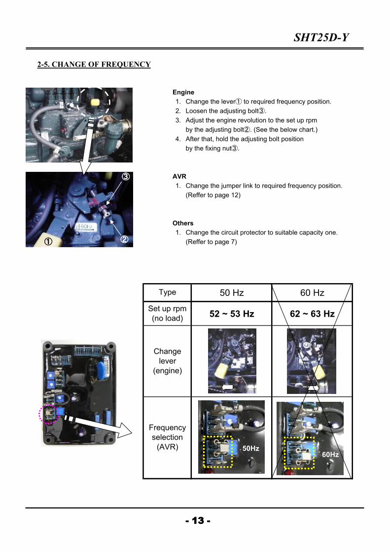
2-5. CHANGE OF FREQUENCY
Engine
1. Change the lever① to required frequency position.
2. Loosen the adjusting bolt③.
3. Adjust the engine revolution to the set up rpm
by the adjusting bolt②. (See the below chart.)
4. After that, hold the adjusting bolt position
by the fixing nut③.
AVR
1. Change the jumper link to required frequency position.
(Reffer to page 12)
Others
1. Change the circuit protector to suitable capacity one.
(Reffer to page 7)
50 Hz 60 Hz
52 ~ 53 Hz 62 ~ 63 Hz
- 13 -- 13 -- 13 -- 13 -
Type
Set up rpm
(no load)
Change
lever
(engine)
Frequency
selection
(AVR)
①①①① ②②②②
③③③③
50Hz60Hz

3. TROUBLESHOOTING SHT25D-Y
3-1. GENERATOR
NOTE : In order to replace the parts in safety, remove negative terminal of battery so as to prevent the battery
and the parts from short-circuiting.
3-1-1. Evident Physical Dedects (Overheating, Noise, Vibrations…)
Excessive overheating of
bearing (With or without
abnormal bearing noise)
Disassemble bearing
* If the has turned blue or if the grease has
turned black, change the bearing.
* Bearing race badly locked (moving in its
housing)
* Bracket misalig
Excessive overheating of
alternator frame
Check
* Air inlets and outlets of
alternator
* Measureing equipment
(Voltmeter-Ammeter)
* Air flow (inlet-outlet) partially clogged or hot
air is being recycled either from alternator or
prime mover.
* Alternatoe over loaded.
Stop the gen-set and check the
installation.
* Three phase alternator is single phase
loaded in excess of acceptable lebel.
Start up with no-load :
if humming persists…* Short-circuit in the alternator stator.
Alternator damaged by a
significant impact which is
followed by humming and
vibration
Stop the gen-set immediately.
* Short-circuit in external circuit.
* Break or deterioration in the coupling.
* Break or twist in shaft extention.
* Shifting or short-circuit or the main field
winding.
Smork, sparks, or flames
issuing from the alternatorStop the set immediately.
* Short-circuit in external circuit
(including wiring between alternator and
control panel).
* Object fallen into the machine.
- 14 -- 14 -- 14 -- 14 -
Fault Action Origin of fault
Excessive vibration and
humming noise coming
from the alternator.

SHT25D-Y
3-1-2. Voltage Faults
* The alternator builds up
and voltage is correct after
battery removal.
* Lack of residual magnetism.
* Check voltage between F1 and F2 of the AVR
(correct value 4~7 V).
* V < 3 V exciter faulty.
* The alternator builds up
but voltage does not reach
nominal value after battery
removal.
* Check the connection of the sensing leads to
the AVR.
* Readjust the trimmer (VOLTS) voltage.
* The alternator builds up
but voltage collapses after
battery removal.
* AVR failure
* Chech the connection of the sensing leads to
the AVR.
* Exiciter windings shorted or open circuit
(check winding).
Voltage too
high
Adjust trimmer
voltage
No adjustment of voltage,
measure voltage between
F1 and F2 on AVR
Voltage between F1 and F2 < 3 V
AVR faulty.
* Check speed for possible cycle irregularity.
* Check out put connections.
* Faulty AVR.
* Speed below nominal on load.
* A rotating diode is open circuit.
* Auxiliary winding is open circuit (check
resistance values).
Voltage between F1 and F2
is < 4 V (D.C.)* Check speed.
Voltage between F1 and F2
is < 3 V (D.C.)
* Fault in rotating diodes.
* Short circuit in main field, check resistance.
* Exciter rotor faulty (check values).
Voltage
collapses
during
normal
operation
Check the AVR, the
surge suppressor,
the rotating diodes
and replace any
defective part
* The output voltage does
not return the nominal
voltage
* Exciter winding faulty (check values).
* Main field faulty (check values).
* Faulty exciter rotor.
Voltage
correct on
no-load, too
low on load
Run on no-load and
check voltage
between F1 and F2
- 15 -- 15 -- 15 -- 15 -
ActionDefect Measure Origin of fault
No voltage at
no load or
start up
Connect a 12V
battery for two or
three seconds to
terminals F1 and F2
from the generator.
Voltage
oscillation
Adjust trimmer
stability* If no result
SHT25D-Y
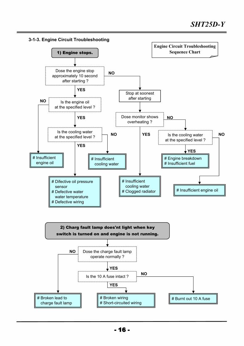
3-1-3. Engine Circuit Troubleshooting
NO
YES
NO
YES NO
NO YES NO
YES
YES
NO
YES
NO
YES
- 16 -- 16 -- 16 -- 16 -
1) Engine stops.
Dose the engine stop
approximately 10 second
after starting ?
Stop at soonest
after startingIs the engine oil
at the specified level ?
Dose monitor shows
overheating ?
Is the cooling water
at the specified level ?Is the cooling water
at the specified level ?
# Insufficient
engine oil # Insufficient
cooling water
# Difective oil pressure
sensor
# Defective water
water temperature
# Defective wiring
# Insufficient
cooling water
# Clogged radiator
# Engine breakdown
# Insufficient fuel
# Insufficient engine oil
2) Charg fault lamp does'nt light when key
switch is turned on and engine is not running.
Dose the charge fault lamp
operate normally ?
Is the 10 A fuse intact ?
# Broken lead to
charge fault lamp
# Broken wiring
# Short-circuited wiring # Burnt out 10 A fuse
Engine Circuit Troubleshooting
Sequence Chart
SHT25D-Y
NO
YES
NO
YES
NO
YES
NO
YES
NO
YES
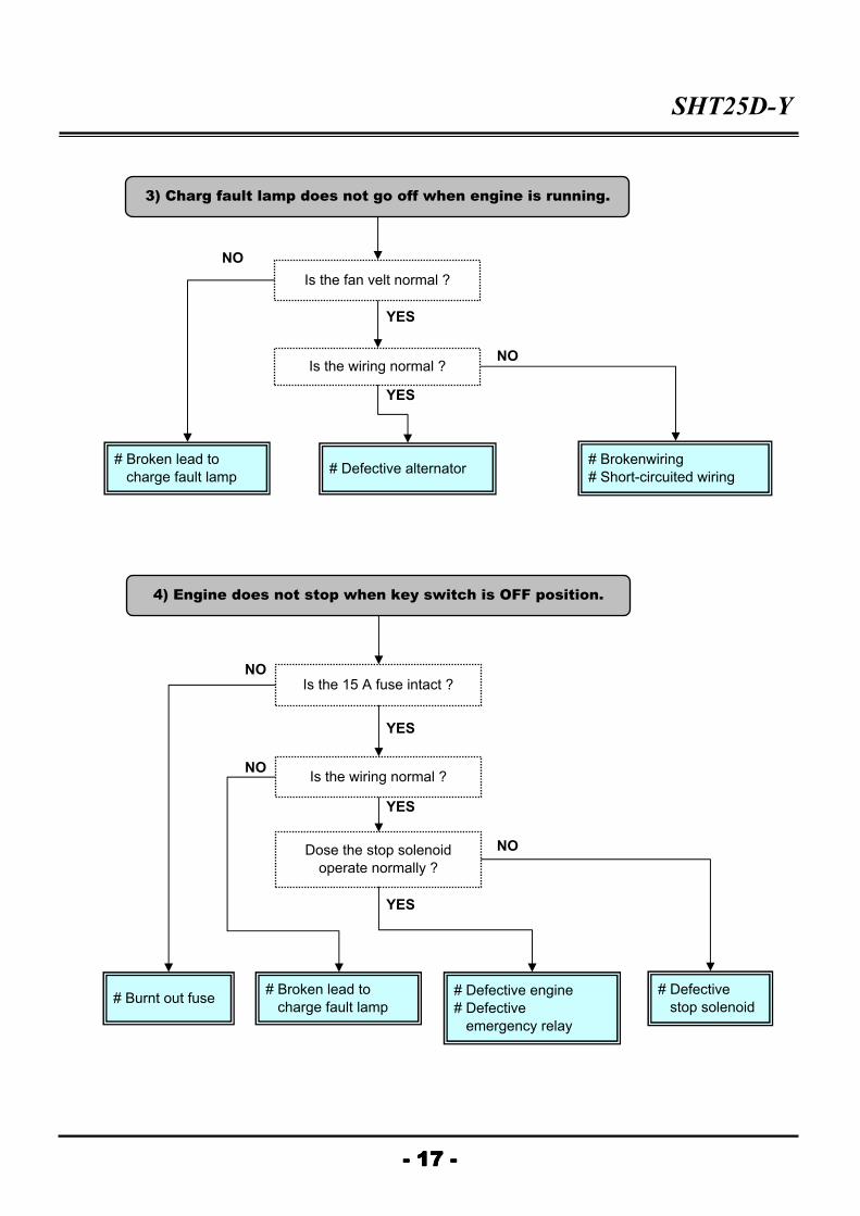
- 17 -- 17 -- 17 -- 17 -
3) Charg fault lamp does not go off when engine is running.
Is the fan velt normal ?
Is the wiring normal ?
# Broken lead to
charge fault lamp # Defective alternator
# Brokenwiring
# Short-circuited wiring
4) Engine does not stop when key switch is OFF position.
Is the wiring normal ?
Dose the stop solenoid
operate normally ?
# Broken lead to
charge fault lamp
# Defective engine
# Defective
emergency relay
# Defective
stop solenoid
Is the 15 A fuse intact ?
# Burnt out fuse

SHT25D-Y
Engine stops during operation.
Engine starts, but stops after about 10 sec.
(Checking method) Are the oil pressure and water temperature monitor lamp normal ?
Oil pressure monitor lamp shows abnormal.
(Checking method) Check the fuse for continuity with an ohmmeter.
Charge fault lamp does not light even
with the key switch turned to "ON"
when the engine is stopped.
Charge fault lamp is not off even
when the engine is running.
Engine does not stop even
after key switch to "OFF"
- 18 -- 18 -- 18 -- 18 -
# Insufficient engine oil Add more oil
# Oil pressure will not go up Check the
related point
Water temperature monitor lamp
shows abnormal. # Insufficient cooling water
Add more
cooling water
# Overheats when water
temperature rises
Check the
related points
# Fuse 10 A burned out Replace
# Charge fault lamp burned Replace
# Wiring disconnection or short-circuit Replace
# Alternator failure Replace
# Broken fan velt Replace
Replace
# Stop solenoid failure Replace
# Wiring disconnection or short-circuit Repair
# Fuse (15 A) disconnection Replace
# Wiring disconnection Replace
Oil pressure and water temperature
monitor lamps are normal. # Oil pressure sensor failure Replace
# Water temp. sensor failure Replace
# Wiring short-circuit Repair
# Emergency relay failure
a) Engine stops.
b) Engine stops.
Dose not pass current.
Engine Circuit
Trouble Diagnosis
SHT25D-Y
3-2. ENGINE
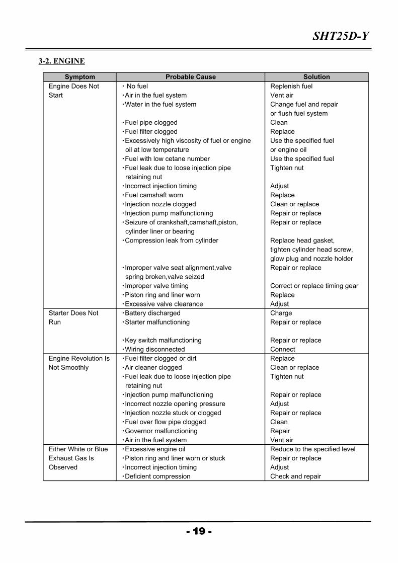
Engine Does Not ・ No fuel Replenish fuel
Start ・Air in the fuel system Vent air
・Water in the fuel system Change fuel and repair
or flush fuel system
・Fuel pipe clogged Clean
・Fuel filter clogged Replace
・Excessively high viscosity of fuel or engine Use the specified fuel
oil at low temperature or engine oil
・Fuel with low cetane number Use the specified fuel
・Fuel leak due to loose injection pipe Tighten nut
retaining nut
・Incorrect injection timing Adjust
・Fuel camshaft worn Replace
・Injection nozzle clogged Clean or replace
・Injection pump malfunctioning Repair or replace
・Seizure of crankshaft,camshaft,piston, Repair or replace
cylinder liner or bearing
・Compression leak from cylinder Replace head gasket,
tighten cylinder head screw,
glow plug and nozzle holder
・Improper valve seat alignment,valve Repair or replace
spring broken,valve seized
・Improper valve timing Correct or replace timing gear
・Piston ring and liner worn Replace
・Excessive valve clearance Adjust
Starter Does Not ・Battery discharged Charge
Run ・Starter malfunctioning Repair or replace
・Key switch malfunctioning Repair or replace
・Wiring disconnected Connect
Engine Revolution Is ・Fuel filter clogged or dirt Replace
Not Smoothly ・Air cleaner clogged Clean or replace
・Fuel leak due to loose injection pipe Tighten nut
retaining nut
・Injection pump malfunctioning Repair or replace
・Incorrect nozzle opening pressure Adjust
・Injection nozzle stuck or clogged Repair or replace
・Fuel over flow pipe clogged Clean
・Governor malfunctioning Repair
・Air in the fuel system Vent air
Either White or Blue ・Excessive engine oil Reduce to the specified level
Exhaust Gas Is ・Piston ring and liner worn or stuck Repair or replace
Observed ・Incorrect injection timing Adjust
・Deficient compression Check and repair
Symptom Probable Cause Solution
- 19 -- 19 -- 19 -- 19 -
SHT25D-Y
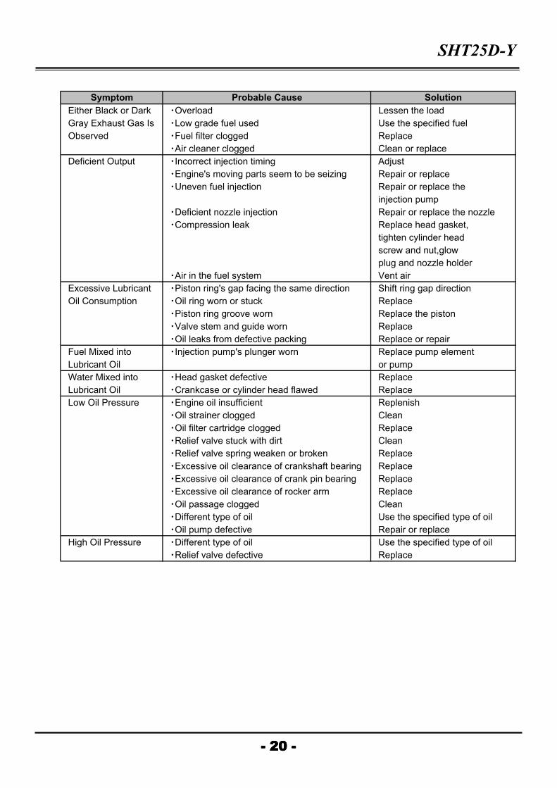
Either Black or Dark ・Overload Lessen the load
Gray Exhaust Gas Is ・Low grade fuel used Use the specified fuel
Observed ・Fuel filter clogged Replace
・Air cleaner clogged Clean or replace
Deficient Output ・Incorrect injection timing Adjust
・Engine's moving parts seem to be seizing Repair or replace
・Uneven fuel injection Repair or replace the
injection pump
・Deficient nozzle injection Repair or replace the nozzle
・Compression leak Replace head gasket,
tighten cylinder head
screw and nut,glow
plug and nozzle holder
・Air in the fuel system Vent air
Excessive Lubricant ・Piston ring's gap facing the same direction Shift ring gap direction
Oil Consumption ・Oil ring worn or stuck Replace
・Piston ring groove worn Replace the piston
・Valve stem and guide worn Replace
・Oil leaks from defective packing Replace or repair
Fuel Mixed into ・Injection pump's plunger worn Replace pump element
Lubricant Oil or pump
Water Mixed into ・Head gasket defective Replace
Lubricant Oil ・Crankcase or cylinder head flawed Replace
Low Oil Pressure ・Engine oil insufficient Replenish
・Oil strainer clogged Clean
・Oil filter cartridge clogged Replace
・Relief valve stuck with dirt Clean
・Relief valve spring weaken or broken Replace
・Excessive oil clearance of crankshaft bearing Replace
・Excessive oil clearance of crank pin bearing Replace
・Excessive oil clearance of rocker arm Replace
・Oil passage clogged Clean
・Different type of oil Use the specified type of oil
・Oil pump defective Repair or replace
High Oil Pressure ・Different type of oil Use the specified type of oil
・Relief valve defective Replace
- 20 -- 20 -- 20 -- 20 -
Symptom Probable Cause Solution
SHT25D-Y
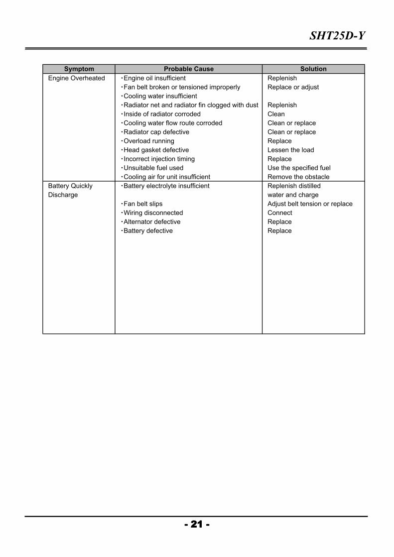
Engine Overheated ・Engine oil insufficient Replenish
・Fan belt broken or tensioned improperly Replace or adjust
・Cooling water insufficient
・Radiator net and radiator fin clogged with dust Replenish
・Inside of radiator corroded Clean
・Cooling water flow route corroded Clean or replace
・Radiator cap defective Clean or replace
・Overload running Replace
・Head gasket defective Lessen the load
・Incorrect injection timing Replace
・Unsuitable fuel used Use the specified fuel
・Cooling air for unit insufficient Remove the obstacle
Battery Quickly ・Battery electrolyte insufficient Replenish distilled
Discharge water and charge
・Fan belt slips Adjust belt tension or replace
・Wiring disconnected Connect
・Alternator defective Replace
・Battery defective Replace
Symptom Probable Cause Solution
- 21 -- 21 -- 21 -- 21 -

4. DISASSEMBLY AND SERVICING SHT25D-Y
4-1. EXTERNAL COMPONENT
Cover, Battery, Draining
1. Place the generator on a firm and level surface.
2. Remove the maitenance cover① and side cover②.
3. Open the drain cock to drain cooling water.
4. Remove the drain plug and drain engine oil.
5. Remove the battery negative cable, and next ,
the plus cable.
6. Remove the fuel tank cap③.
7. Remove the upper cover④.
Fuel tank
8. Return the fuel tank cap to the fuel tank⑤.
9. Close the fuel filter cock.
10. Remove the exhaust pipe and air bleeding pipe
from the fuel filter⑥.
11. Remove the fuel filter.
12. Remove the battery cables from the fuel tank.
13. Remove the fixing bolt of the fuel tank.
14. Remove the fuel tank from maintenance cover side.
Front cover, Control panel
15. Remove the front maintenance cover⑦.
16. Remove the wiring of the lower part on the terminal⑧.
17. Remove the fixing bolt of the terminal.
18. Remove the AVR maintenance cover⑨.
18. Disconnect the connector between the alternator
and AVR.
19. Remove the fixing bolt of the front cover.
Rear cover
20. Remove the fixing bolt⑧ of the exhaust pipe.
21. Remove the upper radiator hose, and next,
lower radiator hose.
22. Remove the fan cover⑪.
22. Remove the fixing bolt of the rear cover.
Battery and battery tray
23. Remove the battery.
23. Remove the battery tray⑫.
- 22 -- 22 -- 22 -- 22 -
⑧⑧⑧⑧
⑤⑤⑤⑤
⑥⑥⑥⑥⑦⑦⑦⑦
⑩⑩⑩⑩
④④④④
①①①①
②②②② ③③③③
⑨⑨⑨⑨
⑪⑪⑪⑪ ⑫⑫⑫⑫
Rear coverRear coverRear coverRear coverFront coverFront coverFront coverFront cover
SHT25D-Y
4-2. GENERATOR
EBS unit
1. Remove the terminal box lid① and D.E. screen②.
2. Remove the nuts③ for generator side mount.
3. Loosen the nuts for engine side mount.
4. Remove the bolts④ for EBS unit⑤.
5. Remove the EBS unit, take care not to damage windings.
EBS rotor
6. Remove the bolts⑥ for EBS rotor⑦.
7. Remove the EBS rotor⑦.
Stater
8. Loosen the fixing bolts⑦ for the D.E. adaptor⑧ slightly.
9. Put a jack under the D.E. adaptor.
10. To avoid damage to the stator and rotor, suspend the
generator with a sling enough to keep it from lifting,
and leave it suspended.
11. Jack up the generator slowly to the position where the
mounting bolts becomes free.
12. To work safety, Remove the fixing bolts⑦.
13. Set a puller⑨ to the N.D.E. bracket, and pull up slowly
till a bearing deviates from bearing housing.
14. Remove a puller⑨.
15. Remove the stator assembly, take care not to damage
windings (main and exciter).
Rotor
16. To avoid damage to the rotor, suspend the rotor with a
sling enough to keep it from lifting, and leave it suspended.
17. Remove the fixing bolts⑩ for the disc coupling.
18. Remove the rotor assembly, take care not to damage winding.
- 23 -- 23 -- 23 -- 23 -
①①①①
②②②②③③③③
④④④④
⑤⑤⑤⑤
⑥⑥⑥⑥
⑦⑦⑦⑦
⑧⑧⑧⑧
JackJackJackJack
⑨⑨⑨⑨
⑩⑩⑩⑩
SHT25D-Y
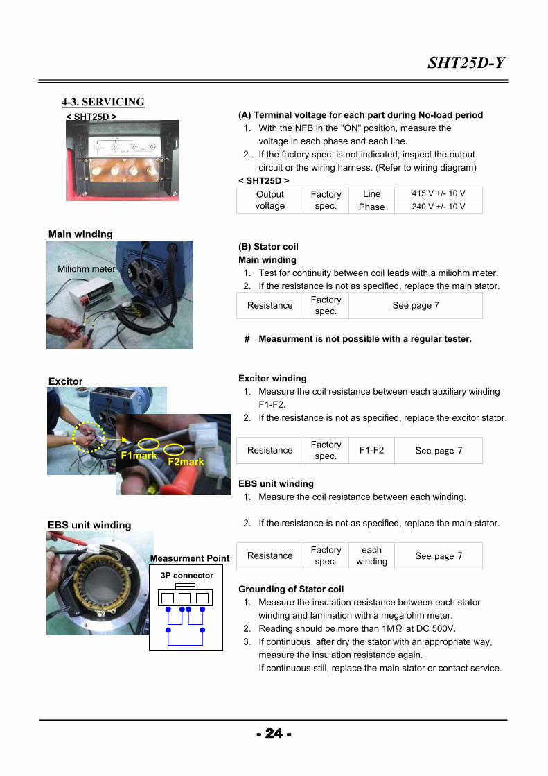
4-3. SERVICING
(A) Terminal voltage for each part during No-load period
1. With the NFB in the "ON" position, measure the
voltage in each phase and each line.
2. If the factory spec. is not indicated, inspect the output
circuit or the wiring harness. (Refer to wiring diagram)
< SHT25D >
Line
Phase
(B) Stator coil
Main winding
1. Test for continuity between coil leads with a miliohm meter.
2. If the resistance is not as specified, replace the main stator.
# Measurment is not possible with a regular tester.
Excitor winding
1. Measure the coil resistance between each auxiliary winding
F1-F2.
2. If the resistance is not as specified, replace the excitor stator.
EBS unit winding
1. Measure the coil resistance between each winding.
2. If the resistance is not as specified, replace the main stator.
Grounding of Stator coil
1. Measure the insulation resistance between each stator
winding and lamination with a mega ohm meter.
2. Reading should be more than 1MΩ at DC 500V.
3. If continuous, after dry the stator with an appropriate way,
measure the insulation resistance again.
If continuous still, replace the main stator or contact service.
See page 7
ResistanceFactory
spec.
- 24 -- 24 -- 24 -- 24 -
ResistanceFactory
spec.See page 7
415 V +/- 10 V
240 V +/- 10 V
Factory
spec.
Output
voltage
F1-F2
each
windingSee page 7
ResistanceFactory
spec.
< SHT25D >
Miliohm meter
F1markF2mark
Main winding
Excitor
EBS unit winding
3P connector
Measurment Point

SHT25D-Y
(C) Rotor coil
Main rotor winding①①①① and Excitor rotor winding②②②②
1. Remove the field coil end at the rotating rectifire assembly.
2. Measure the coil resistance between each end of field coil.
3. If the resistance is not as specified, replace the rotor
assembly.
Main
Excitor
# Measurment is not possible with a regular tester.
Grounding of Rotor coil
1. Measure the insulation resistance between each rotor
winding and lamination with a mega ohm meter.
2. Reading should be more than 1MΩ at DC 500V.
3. If continuous, after dry the rotor with an appropriate way,
measure the insulation resistance again.
If continuous still, replace the main rotor or contact service.
(D) Initial excitation method
The generator is self exciting from the residual magnetism
of the magnetic circuit of the excitor. When first tested
(at the factory) this magnetic circuit is magnetized but
after a breakdown it may be necessary to remagnetize.
1. 12V battery is used for initial excitation.
2. Stop the generator and disconnect the AVR cable.
3. Connect the battery's positive and negative cables
to the generator's F1 and F2 terminal, respectively,
for just 2 or 3 seconds.
4. Connect and run the generator.
# If the connection has the wrong polarity or different
position (such as F1 and F2 side) magnetization is
reversely reduced.
See page 7
- 25 -- 25 -- 25 -- 25 -
ResistanceFactory
spec.
①①①①②②②②
(Excitor winding)
Mega ohm meter
Miliohm meter
SHT25D-Y
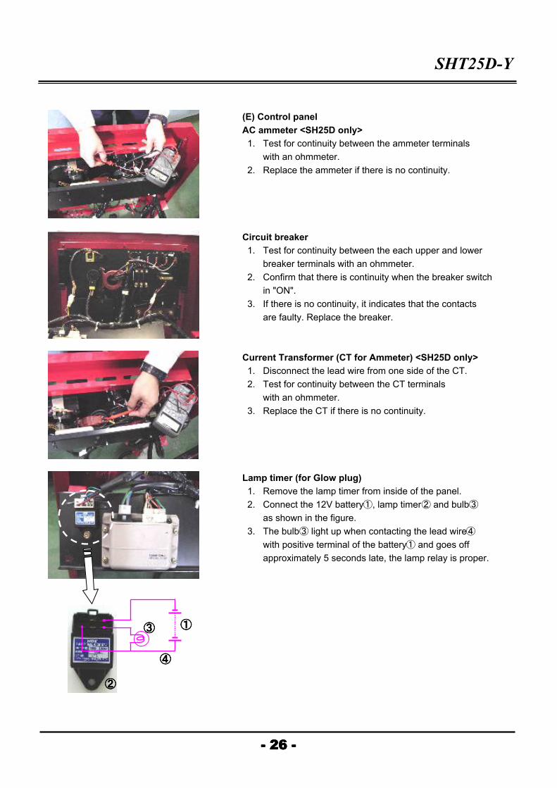
(E) Control panel
AC ammeter <SH25D only>
1. Test for continuity between the ammeter terminals
with an ohmmeter.
2. Replace the ammeter if there is no continuity.
Circuit breaker
1. Test for continuity between the each upper and lower
breaker terminals with an ohmmeter.
2. Confirm that there is continuity when the breaker switch
in "ON".
3. If there is no continuity, it indicates that the contacts
are faulty. Replace the breaker.
Current Transformer (CT for Ammeter) <SH25D only>
1. Disconnect the lead wire from one side of the CT.
2. Test for continuity between the CT terminals
with an ohmmeter.
3. Replace the CT if there is no continuity.
Lamp timer (for Glow plug)
1. Remove the lamp timer from inside of the panel.
2. Connect the 12V battery①, lamp timer② and bulb③
as shown in the figure.
3. The bulb③ light up when contacting the lead wire④
with positive terminal of the battery① and goes off
approximately 5 seconds late, the lamp relay is proper.
- 26 -- 26 -- 26 -- 26 -
①①①①
②②②②
③③③③
④④④④

SHT25D-Y
Oil pressure sensor
1. The normal oil pressure sensor has continuity when
the engine is stopped and has no continuity while the
engine is running.
2. Replace the sensor if it is defective.
Water temperature sensor
1. Insert the water temperature sensor in the engine oil,
and continue the circuit when the oil temperature rises
above than 115 +/- 3℃.
2. Check that the resistance is 0 ohm in case sensor
is defective.
Emergency relay circuit
1. When the engine is running at rated rpm, connect the
lead wires to the terminal of the oil pressure sensor or
the water temperature sensor.
2. Aiso ground the other end of the lead wires to an
unpainted portion of the engine frame.
(In normal operation)
・ The stop solenoid activates and the engine stopes
automatically.
・ As the stop solenoid is acivated again after 10 +/- 3 sec
of its first engagement, a 'tick' sound can be heard.
- 27 -- 27 -- 27 -- 27 -