XT Service Manual Pro2V080 Rev 5.6B5 5-15-07
77
Service Manual Rev 5.6B5 with software Pro2V080 and Pro2V081 XT SERIES Service Manual 820 Lakeside Drive – Gurnee, IL 60031 Phone: 1-800- 374-8266 Fax: (847) 855-9650 www.drivecon.com This document and the information contained herein, is the exclusive property of Drivecon, Inc. and represents a non-public, confidential and proprietary trade secret that may not be reproduced, disclosed to third parties, altered or otherwise employed in any manner whatsoever without the express written consent of Drivecon, Inc. Copyright © 2006 Drivecon, Inc. All rights reserved.
Transcript of XT Service Manual Pro2V080 Rev 5.6B5 5-15-07

Service Manual Rev 5.6B5 with software Pro2V080
and Pro2V081
XT SERIES
Service Manual
820 Lakeside Drive – Gurnee, IL 60031
Phone: 1-800- 374-8266 Fax: (847) 855-9650
www.drivecon.com
This document and the information contained herein, is the exclusive property of
Drivecon, Inc. and represents a non-public, confidential and proprietary trade secret
that may not be reproduced, disclosed to third parties, altered or otherwise employed
in any manner whatsoever without the express written consent of Drivecon, Inc.
Copyright © 2006 Drivecon, Inc. All rights reserved.

Page 1
Service Manual Pro2V080 Pro2V081
Drivecon reserves the right to al ter or amend the above information wi thout notice12/18/06 • rev 5.6B5 for Pro2V080 or Pro2V081 software
CAUTION
1. Before starting, read the instructions carefully.
2. Verify all of the connections are in done in accordance to the drawings.
3. Verify the motor supply is connected correctly; faulty connections will damage the drive.
4. Check to make sure that the drive’s cover is properly installed.
5. High voltages are present in the drive. Switch the power off and wait 5 minutes before opening the cover.
6. Insulation resistance test with a megger requires special precautions.
7. Do not make any measurements inside the device when it is connected to the 3-phase power supply.
8. Do not touch the components on the circuit boards. Static voltage discharge may cause damage to the IC-circuits.
9. Check to make sure that all ventilation holes are clear and uncovered.
10. Check to make sure that hot air coming from the dynamic braking resistors cannot cause any damage.
11. Do not make any inspections unless the supply has been disconnected at the main disconnect switch.
12. It is forbidden to use radiophones or portable phones near this device with the doors open.
13. All the doors and covers must be closed during crane operation.

Page 2
Service Manual Pro2V080 Pro2V081
Drivecon reserves the right to al ter or amend the above information wi thout notice12/18/06 • rev 5.6B5 for Pro2V080 or Pro2V081 software
CONTENTS
1 GENERAL....................................................................................................................... 4 1.1 Technical data ...................................................................................................... 4 1.2 Type mark coding.................................................................................................. 5 1.3 Basic description ................................................................................................... 6 1.4 Functional description............................................................................................ 7 1.5 Control methods.................................................................................................... 8 1.6 Mechanical brake control ..................................................................................... 10 1.7 Motor control modes................................................................................... ......... 10 1.8 EMC................................................................................................................... 11
1.8.1 Fulfilled EMC-standards ............................................................................ 12
2 INSTALLATION ............................................................................................................. 13 2.1 Cooling............................................................................................................... 13 2.2 Power cabling ..................................................................................................... 13 2.3 Control wiring...................................................................................................... 15 2.4 EMC compatible grounding .................................................................................. 16
3 START-UP PROCEDURE .............................................................................................. 17 3.1 Visual checks...................................................................................................... 17 3.2 Checks before the f irst test run ............................................................................ 17 3.3 Test run without load ........................................................................................... 18 3.4 Test run with load................................................................................................ 18 3.5 After the test run and autotuning .......................................................................... 18
4 PARAMETER ADJUSTMENTS ....................................................................................... 19 4.1 Control keypad operation ..................................................................................... 19
4.1.1 Navigation on the control keypad ............................................................... 20 4.1.2 Value line editing...................................................................................... 20 4.1.3 Passwords................................................................................................ 21 4.1.4 Special button functions and shortcuts ....................................................... 21 4.1.5 Monitoring................................................................................................ 22
4.2 Input selections................................................................................................... 23 4.3 Speed superv ision settings .................................................................................. 24
4.3.1 Functional test run for SSU ....................................................................... 26 4.4 Open Loop motor parameter adjustments.............................................................. 27
4.4.1 Open Loop speed control for hoisting ......................................................... 27 4.4.2 Open Loop motor parameters for traveling ................................................. 27 4.4.3 Open Loop autotuning for traveling, frequency control................................. 28 4.4.4 Open Loop manual tuning for traveling....................................................... 28 4.4.5 Open Loop manual tuning for traveling, frequency control ........................... 29 4.4.6 Open Loop manual tuning for traveling, current control ............................... 29
4.5 Closed Loop motor parameter adjustments............................................................ 30 4.5.1 Closed Loop rated motor parameters ......................................................... 30 4.5.2 Closed Loop autotuning, speed control ....................................................... 31 4.5.3 Closed Loop manual tuning for hoisting, speed control ................................ 34
4.6 Brake Slip Feature……………………………………………………………………………….37 4.6.1 Description of brake slip feature………………………………………...…………..37 4.6.2 Activation of brake slip feature……………………………..……………..………..38 4.6.3 Brake Slip Feature Field Testing Procedure…………………………..……….….38 4.6.4 What to do in case of brake slip……………………………………………………..39 4.6.5 Service on hoist motor/encoder/brake with Brake Slip feature active………...40
5 PARAMETER DESCRIPTIONS....................................................................................... 41

Page 3
Service Manual Pro2V080 Pro2V081
Drivecon reserves the right to al ter or amend the above information wi thout notice12/18/06 • rev 5.6B5 for Pro2V080 or Pro2V081 software
6 COMPONENTS ............................................................................................................. 54 6.1 Inverter .............................................................................................................. 54
6.1.1 Power supply unit (PSU) ........................................................................... 56 6.1.2 Control unit (CSU) .................................................................................... 56 6.1.3 Basic I/O board (Slot A) ............................................................................ 57 6.1.4 Relay / Thermistor board (Slot B) .............................................................. 58 6.1.5 SSU Speed Superv ision board (Slot C) ...................................................... 58 6.1.6 I/O Extension board (Slot D)...................................................................... 59 6.1.7 Relay Extension board (Slot E) .................................................................. 59 6.1.8 Prof ibus board (Slot E) ............................................................................. 60
6.2 Reference potentiometer...................................................................................... 61 6.3 Speed sensors .................................................................................................... 62
6.3.1 Encoder ................................................................................................... 62 6.3.2 Bearing Sensor......................................................................................... 63 6.3.3 Proximity switch ....................................................................................... 64 6.3.4 Buffer amplifier KAE234 ........................................................................... 65
6.4 Brake controllers ................................................................................................. 66 6.4.1 REC12-690+DC ........................................................................................ 66 6.4.2 ESD141 ................................................................................................ ... 66
7 TROUBLESHOOTING.................................................................................................... 67 7.1 Field repair actions.............................................................................................. 67 7.2 Inverter fault codes ............................................................................................. 68
7.2.1 Fault time data record............................................................................... 73 7.2.2 Fault Counter ......................................................................................... .. 73
7.3 Inverter Alarm codes .................................................................................. ......... 74
8 SERVICE...................................................................................................................... 75 8.1 DC-bus electrolytic capacitors .............................................................................. 75
8.1.1 Re-forming after a long storage period ....................................................... 75
9 DRAWINGS ........................................... ....................................................................... 76
Page 4
Service Manual Pro2V080 Pro2V081
Drivecon reserves the right to al ter or amend the above information wi thout notice12/18/06 • rev 5.6B5 for Pro2V080 or Pro2V081 software
1 GENERAL
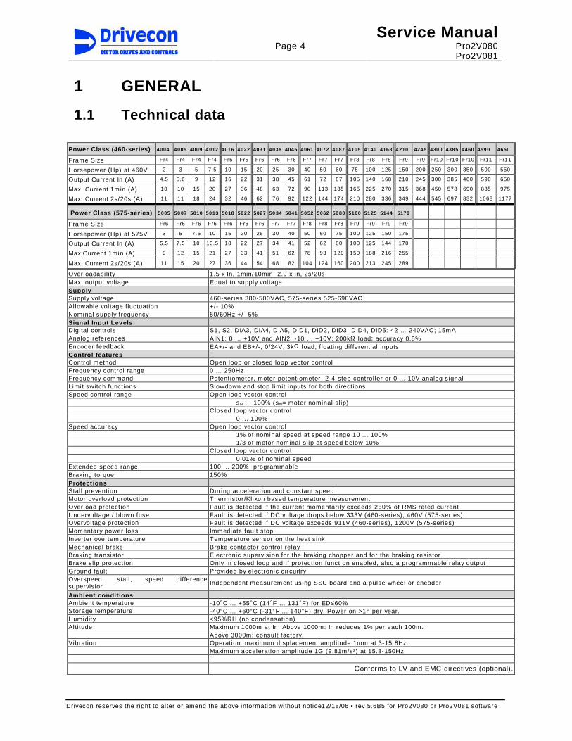
1.1 Technical data
Overloadabi li ty 1.5 x In, 1min/10min; 2.0 x In, 2s/20s Max. output voltage Equal to supply vol tage Supply Supply voltage 460-ser ies 380-500VAC, 575-series 525-690VAC Al lowable vol tage f luctuation +/- 10% Nominal supply frequency 50/60Hz +/- 5% Signal Input Levels Digi tal controls S1, S2, DIA3, DIA4, DIA5, DID1, DID2, DID3, DID4, DID5: 42 … 240VAC; 15mA Analog references AIN1: 0 … +10V and AIN2: -10 … +10V; 200kΩ load; accuracy 0.5% Encoder feedback EA+/- and EB+/-; 0/24V; 3kΩ load; f loating dif ferential inputs Control features Control method Open loop or closed loop vector control Frequency control range 0 ... 250Hz Frequency command Potentiometer, motor potentiometer , 2-4-step controller or 0 ... 10V analog signal Limi t switch functions Slowdown and stop limit inputs for both directions Speed control range Open loop vector control sN . .. 100% (sN= motor nominal slip) Closed loop vector control 0 ... 100% Speed accuracy Open loop vector control
1% of nominal speed at speed range 10 .. . 100% 1/3 of motor nominal slip at speed below 10%
Closed loop vector control 0.01% of nominal speed Extended speed range 100 ... 200% programmable Braking torque 150% Protect ions Stal l prevention During acceleration and constant speed Motor overload protection Thermistor /Klixon based temperature measurement Overload protection Fault is detected if the current momentarily exceeds 280% of RMS rated current Undervol tage / blown fuse Fault is detected if DC voltage drops below 333V (460-series), 460V (575-ser ies) Overvol tage protection Fault is detected if DC voltage exceeds 911V (460-series), 1200V (575-series) Momentary power loss Immediate fault stop Inverter overtemperature Temperature sensor on the heat sink Mechanical brake Brake contactor control relay Braking transistor Electronic supervision for the braking chopper and for the braking resistor Brake slip protection Only in closed loop and if protection function enabled, also a programmable relay output Ground fault Provided by electronic circuitry Overspeed, stall , speed difference supervision
Independent measurement using SSU board and a pulse wheel or encoder
Ambient conditions Ambient temperature -10°C ... +55°C (14°F ... 131°F) for ED≤60% Storage temperature -40°C ... +60°C (-31°F ... 140°F) dry. Power on >1h per year. Humidity <95%RH (no condensation) Al titude Maximum 1000m at In. Above 1000m: In reduces 1% per each 100m. Above 3000m: consult factory. Vibration Operation: maximum displacement ampl itude 1mm at 3-15.8Hz. Maximum acceleration ampl itude 1G (9.81m/s²) at 15.8-150Hz Conforms to LV and EMC directives (optional).
Power Class (460-series) 4004 4005 4009 4012 4016 4022 4031 4038 4045 4061 4072 4087 4105 4140 4168 4210 4245 4300 4385 4460 4590 4650
Frame Size Fr4 Fr4 Fr4 Fr4 Fr5 Fr5 Fr6 Fr6 Fr6 Fr7 Fr7 Fr7 Fr8 Fr8 Fr8 Fr9 Fr9 Fr10 Fr10 Fr10 Fr11 Fr11
Horsepower (Hp) at 460V 2 3 5 7.5 10 15 20 25 30 40 50 60 75 100 125 150 200 250 300 350 500 550
Output Current In (A) 4.5 5.6 9 12 16 22 31 38 45 61 72 87 105 140 168 210 245 300 385 460 590 650
Max. Current 1min (A) 10 10 15 20 27 36 48 63 72 90 113 135 165 225 270 315 368 450 578 690 885 975
Max. Current 2s/20s (A) 11 11 18 24 32 46 62 76 92 122 144 174 210 280 336 349 444 545 697 832 1068 1177
Power Class (575-series) 5005 5007 5010 5013 5018 5022 5027 5034 5041 5052 5062 5080 5100 5125 5144 5170
Frame Size Fr6 Fr6 Fr6 Fr6 Fr6 Fr6 Fr6 Fr7 Fr7 Fr8 Fr8 Fr8 Fr9 Fr9 Fr9 Fr9
Horsepower (Hp) at 575V 3 5 7.5 10 15 20 25 30 40 50 60 75 100 125 150 175
Output Current In (A) 5.5 7.5 10 13.5 18 22 27 34 41 52 62 80 100 125 144 170
Max Current 1min (A) 9 12 15 21 27 33 41 51 62 78 93 120 150 188 216 255
Max. Current 2s/20s (A) 11 15 20 27 36 44 54 68 82 104 124 160 200 213 245 289
Page 5
Service Manual Pro2V080 Pro2V081
Drivecon reserves the right to al ter or amend the above information wi thout notice12/18/06 • rev 5.6B5 for Pro2V080 or Pro2V081 software
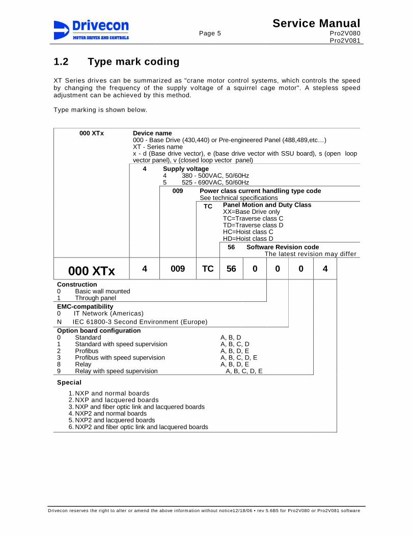
1.2 Type mark coding XT Series drives can be summarized as "crane motor control systems, which controls the speed by changing the frequency of the supply voltage of a squirrel cage motor". A stepless speed adjustment can be achieved by this method. Type marking is shown below.
Device name 000 - Base Drive (430,440) or Pre-engineered Panel (488,489,etc…) XT - Series name x - d (Base drive vector), e (base drive vector with SSU board), s (open loop vector panel), v (closed loop vector panel)
Supply voltage 4 380 - 500VAC, 50/60Hz 5 525 - 690VAC, 50/60Hz
Power class current handling type code See technical specifications
Panel Motion and Duty Class XX=Base Drive only TC=Traverse class C TD=Traverse class D HC=Hoist class C HD=Hoist class D
000 XTx
4
009
TC
56 Software Revision code The latest rev ision may differ
000 XTx 4 009 TC 56 0 0 0 4
Construction 0 Basic wall mounted 1 Through panel
EMC-compatibility 0 IT Network (Americas) N IEC 61800-3 Second Environment (Europe) Option board configuration 0 Standard A, B, D 1 Standard with speed supervision A, B, C, D 2 Profibus A, B, D, E 3 Profibus with speed supervision A, B, C, D, E 8 Relay A, B, D, E 9 Relay with speed supervision A, B, C, D, E
Special
1. NXP and normal boards 2. NXP and lacquered boards 3. NXP and fiber optic link and lacquered boards 4. NXP2 and normal boards 5. NXP2 and lacquered boards 6. NXP2 and fiber optic link and lacquered boards
Page 6
Service Manual Pro2V080 Pro2V081
Drivecon reserves the right to al ter or amend the above information wi thout notice12/18/06 • rev 5.6B5 for Pro2V080 or Pro2V081 software
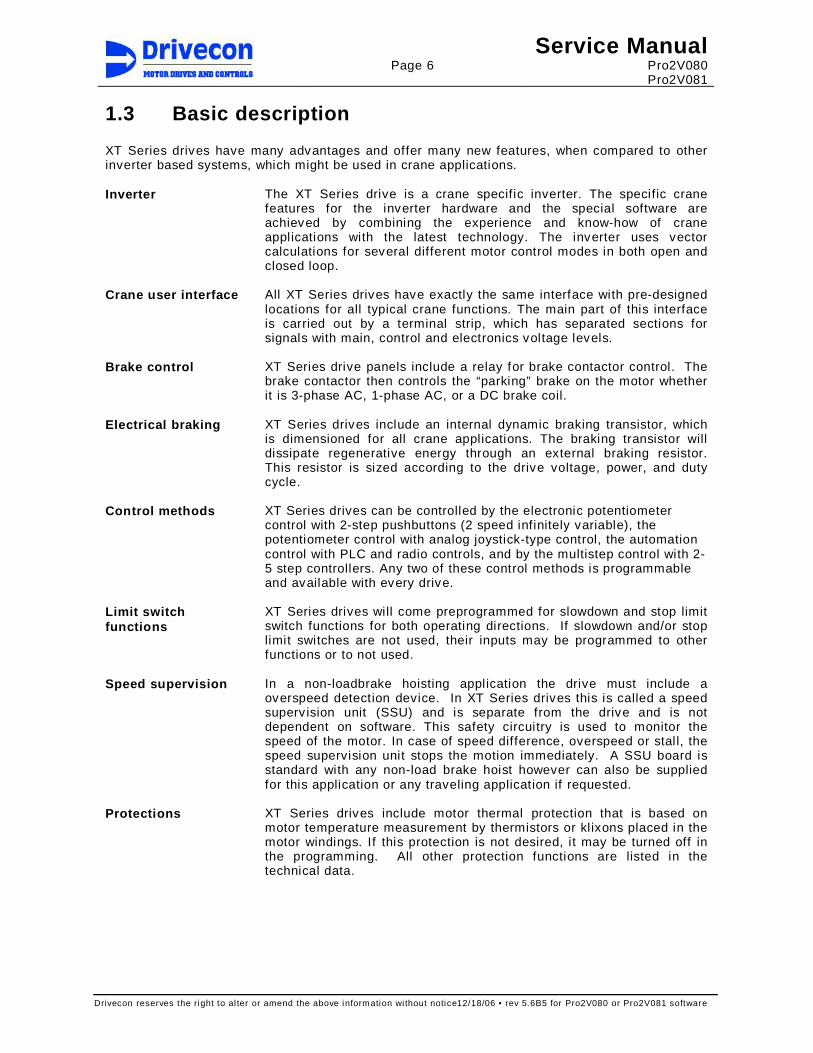
1.3 Basic description XT Series drives have many advantages and offer many new features, when compared to other inverter based systems, which might be used in crane applications. Inverter The XT Series drive is a crane specific inverter. The specific crane
features for the inverter hardware and the special software are achieved by combining the experience and know-how of crane applications with the latest technology. The inverter uses vector calculations for several different motor control modes in both open and closed loop.
Crane user interface All XT Series drives have exactly the same interface with pre-designed locations for all typical crane functions. The main part of this interface is carried out by a terminal strip, which has separated sections for signals with main, control and electronics voltage levels.
Brake control XT Series drive panels include a relay for brake contactor control. The brake contactor then controls the “parking” brake on the motor whether it is 3-phase AC, 1-phase AC, or a DC brake coil.
Electrical braking XT Series drives include an internal dynamic braking transistor, which is dimensioned for all crane applications. The braking transistor will dissipate regenerative energy through an external braking resistor. This resistor is sized according to the drive voltage, power, and duty cycle.
Control methods XT Series drives can be controlled by the electronic potentiometer control with 2-step pushbuttons (2 speed infinitely variable), the potentiometer control with analog joystick-type control, the automation control with PLC and radio controls, and by the multistep control with 2-5 step controllers. Any two of these control methods is programmable and available with every drive.
Limit switch functions
XT Series drives will come preprogrammed for slowdown and stop limit switch functions for both operating directions. If slowdown and/or stop limit switches are not used, their inputs may be programmed to other functions or to not used.
Speed supervision In a non-loadbrake hoisting application the drive must include a overspeed detection device. In XT Series drives this is called a speed superv ision unit (SSU) and is separate from the drive and is not dependent on software. This safety circuitry is used to monitor the speed of the motor. In case of speed difference, overspeed or stall, the speed supervision unit stops the motion immediately. A SSU board is standard with any non-load brake hoist however can also be supplied for this application or any traveling application if requested.
Protections XT Series drives include motor thermal protection that is based on motor temperature measurement by thermistors or kl ixons placed in the motor windings. If this protection is not desired, it may be turned off in the programming. All other protection functions are listed in the technical data.

Page 7
Service Manual Pro2V080 Pro2V081
Drivecon reserves the right to al ter or amend the above information wi thout notice12/18/06 • rev 5.6B5 for Pro2V080 or Pro2V081 software
1.4 Functional description See circuit diagrams for following descriptions of operation. Operation when power is switched on
- Slow down limit switches S11 and S21, and stop limit switches S12 and S22 are assumed to be normally closed, as well as the emergency stop button ES.
- The control voltage is supplied to the drive’s control inputs (externally supplied 42VAC…230VAC control voltage). When the supply voltage is connected to the drive’s power supply and inverter wil l power up. If the control voltage ok and the ready circuit has all of its contacts closed, drive will be ready to operate in about 1-2 seconds.
- If either one of the direction signals S1 or S2 is on, the display shows F6 and running can begin only after the direction signals have been turned off for 300ms.
Normal operation – For the description of the speed reference setting options see
chapter 1.5 "Control methods". – Operation starts when one of the directional inputs is given to the
drive. The drive will then close the ROB2 relay and energize the K7 brake contactor, which will cause the “parking” brake to open. The drive will then accelerate according to the acceleration ramp settings to the requested speed.
– When the directional input is removed from the drive, it wil l stop according to the deceleration ramp settings and finish by controlling the “parking” brake to set and hold the motor.
– The dynamic braking resistor will dissipate the regenerative energy during deceleration and hoisting in the down direction. The power supplied to the resistor is controlled by the drive. If the braking resistor fan(s) are included in an external resistor unit, they will start to operate when power is supplied to the braking resistors. The fan cooling will continue for about 4-5 minutes after electrical regenerative braking to ensure that the temperature of the dynamic braking resistors drops below 150°C (302°F).
Other features – Slowdown limit switches S11 and S21 provide position dependent
f requency l imiting. – Any reason that causes the ready circuit to open wil l stop the
operation of drive and sets the mechanical “parking” brake. – In case of an overload (motor overheating, etc.), the hoisting can be
disabled by removing the direction signal. – Thermistor or Klixon interface function can be used when required. – When the stop limit switch S12 or S22 opens, the brake contactor K7
de-energizes and the mechanical “parking” brake will stop the motion.
– Independent speed superv ision unit (SSU) for applications with speed feedback.
– The speed measurement and supervision can be done either using an encoder, bearing encoder, or pulse sensor. The measured signals are square wave pulses. The frequency of the pulses is proportional to the speed of the motor and if the frequency is too high, overspeed is detected. If there are no pulses a stall situation is detected. If the actual speed differs too much from the supply frequency to the motor, the speed difference supervision stops the motion.
– When using a proximity switch or bearing sensor a buffer amplif ier should be used to amplify the sensor pulses and fi lter out disturbances. This amplifier should be located as close to the motor as possible.

Page 8
Service Manual Pro2V080 Pro2V081
Drivecon reserves the right to al ter or amend the above information wi thout notice12/18/06 • rev 5.6B5 for Pro2V080 or Pro2V081 software
1.5 Control methods There are four different control methods (command modes) available. At any given time 2 different control modes may be used. A selector switch and programming of the drive is required to select the desired control method when using 2 different control modes. Instructions on how to program the drive for each different type of control can be found below. EP Electronic motor potentiometer function.
- Stepless control using a 2-step pushbutton controller (2 speed infinitely variable).
- EP3 stepless control using a 3-step controller (3 speed infinitely variable).
PO Potentiometer control using a joystick type controller.
- Requires a single 15V power supply (supplied by the drive). - Additional amplifier is not required.
AU Automation control - For any control dev ice with an output in the range of 0-10V. - E.g. radio-controls, process computers.
MS Multistep control (2-5 steps as standard). - Requires programmable digital inputs for each speed
reference step.
Command mode selection
The command mode (EP, PO or AU) is selected by the CMS and AP inputs to the drive. Normally the selection can be done only when the motion is stopped (not when running), but in special applications it may be possible.
PO- and AU-modes PO and AU modes select either of the analog inputs for speed reference. Both analog inputs can be adjusted from 0V to 10V (radio or PLC-reference) or from 10V to 6.7V (potentiometer). As default, Ain1 is used in PO-mode and Ain2 is used in AU-mode.
Ain1 / PO Ain1 / PO Ain2 / AU Ain2 / AU Ain1 / PO
DIA3 AP not used AP not used AP not used AP = 0 AP = 1
DIA4 CMS not used
CMS = 0 CMS = 1 CMS = 1 CMS = 1
EP-mode EP-mode selects the AP-button for speed reference. EP step 1 is
command for minimum speed or hold speed. EP step 2 is the acceleration command.
EP step 1 EP step 2 EP step 1 EP step 2
DIA3 AP = 0 AP = 1 AP = 0 AP = 1
DIA4 CMS not used
CMS not used
CMS = 0 CMS = 0
Synchronization If required, two or more XT Series drives can be run in precise digital
synchronization. A separate synchronization controller is needed for this. The same speed reference (in EP- or PO-mode) and the correction signal are connected to each drive. The speed reference signal of each drive can also be modified separately by a PLC. Parameter selection and proper tuning activate the synchronization functionality.
Page 9
Service Manual Pro2V080 Pro2V081
Drivecon reserves the right to al ter or amend the above information wi thout notice12/18/06 • rev 5.6B5 for Pro2V080 or Pro2V081 software
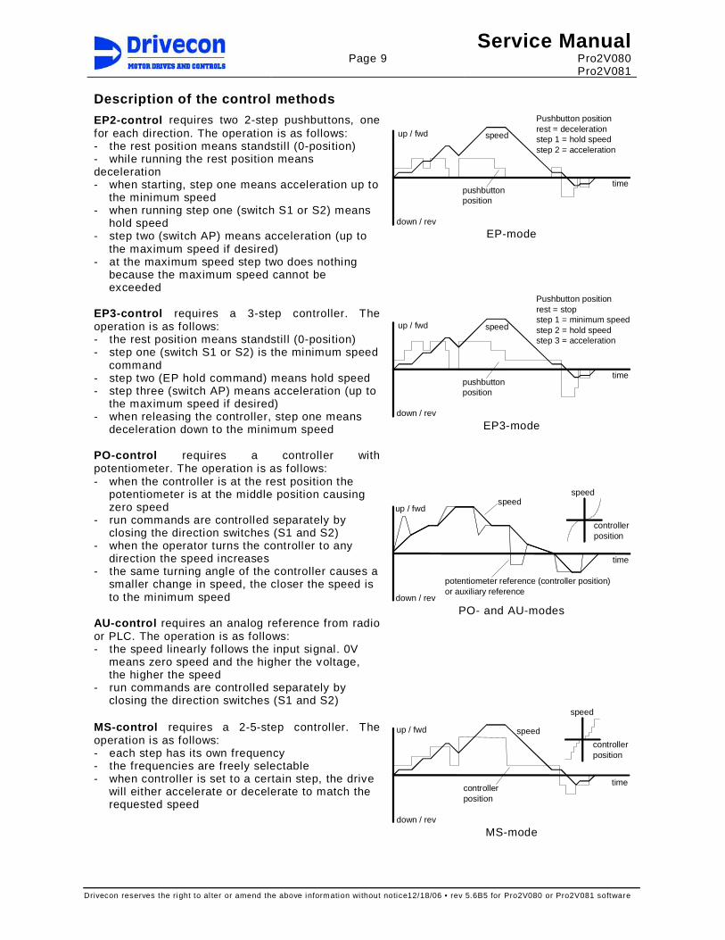
Description of the control methods
EP2-control requires two 2-step pushbuttons, one for each direction. The operation is as follows: - the rest position means standstil l (0-position) - while running the rest position means deceleration - when starting, step one means acceleration up to
the minimum speed - when running step one (switch S1 or S2) means
hold speed - step two (switch AP) means acceleration (up to
the maximum speed if desired) - at the maximum speed step two does nothing
because the maximum speed cannot be exceeded
Pushbutton positionrest = decelerationstep 1 = hold speedstep 2 = acceleration
speed
pushbuttonposition
up / fwd
down / rev
time
EP-mode
EP3-control requires a 3-step controller. The operation is as follows: - the rest position means standstil l (0-position) - step one (switch S1 or S2) is the minimum speed
command - step two (EP hold command) means hold speed - step three (switch AP) means acceleration (up to
the maximum speed if desired) - when releasing the controller, step one means
deceleration down to the minimum speed
speed
Pushbutton positionrest = stopstep 1 = minimum speedstep 2 = hold speedstep 3 = acceleration
pushbuttonposition
up / fwd
down / rev
time
EP3-mode
PO-control requires a controller with potentiometer. The operation is as follows: - when the controller is at the rest position the
potentiometer is at the middle position causing zero speed
- run commands are controlled separately by closing the direction switches (S1 and S2)
- when the operator turns the controller to any direction the speed increases
- the same turning angle of the controller causes a smaller change in speed, the closer the speed is to the minimum speed
AU-control requires an analog reference from radio or PLC. The operation is as follows: - the speed linearly follows the input signal. 0V
means zero speed and the higher the voltage, the higher the speed
- run commands are controlled separately by closing the direction switches (S1 and S2)
up / fwd
down / rev
speedspeed
controllerposition
time
potentiometer reference (controller position)or auxiliary reference
PO- and AU-modes
MS-control requires a 2-5-step controller. The operation is as follows: - each step has its own frequency - the frequencies are freely selectable - when controller is set to a certain step, the drive
will either accelerate or decelerate to match the requested speed
speed
controllerposition
up / fwd
down / rev
time
speed
controller position
MS-mode

Page 10
Service Manual Pro2V080 Pro2V081
Drivecon reserves the right to al ter or amend the above information wi thout notice12/18/06 • rev 5.6B5 for Pro2V080 or Pro2V081 software
1.6 Mechanical brake control The brake is controlled so that while starting the motor generates torque f irst and then the brake is opened. The same applies for stopping; while the brake is being closed, the motor still generates torque. During a direction change, the brake is held open. The drive wil l decelerate the motor to a stop according to the set deceleration time when the run command is removed, so the brake is used only as a holding brake. This way brake wear is minimized. Only if a fault occurs or the emergency stop button is pushed will cause the brake to close immediately stopping the motor and the load. All motors used on cranes should use some type of electromechanical brake. Different applications may require a different type of brake. Also, different applications may require this brake to be used differently. As a default, XT Series drive panels are wired to control a single-phase AC brake. If a 3-phase brake is to be used, some wiring changes will be required. If a DC brake is being used, a brake rectifier will need to be used. The type brake rectifier that is required wil l depend upon the size and voltage of the brake coil.
1.7 Motor control modes Open loop XT Series drives have a built-in motor model, which calculates - one thousand times per second - the values of the motor. The input data needed for the calculation is the instantaneous value of the motor voltage from the ASIC and the measured motor current. Motor magnetic flux and shaft torque are calculated in the motor model based on the nameplate data parameters taken from motor. Open loop vector control
Speedref
InverterAsic
CurrentVectorcalculation
SpeedControl
Torque
Flux
ref
M3~
Frequency control Open loop (mode 0)
In Open Loop Frequency Control, the frequency supplied to the motor follows the frequency reference signal given to the drive. The actual rotating speed depends on load and is equal to the slip below or above the output frequency. Even with frequency control, the vector calculation is used to keep the magnetization at a correct level for optimized torque.
Current control Open Loop (mode 1)
In Open Loop Current Control, the frequency supplied to the motor fol lows the frequency reference signal given to the drive. The motor is current control led in smaller frequencies (typically <10Hz) and in higher frequencies the motor is voltage controlled. The current control ensures that in small frequencies the speed of the motor is almost independent of the load.
Closed loop The closed loop vector control also includes a motor model, which has simpler configuration than the open loop vector control. This is because an additional input data from the incremental encoder is available, thus eliminating additional calculations inside the drive. This measurement of the rotation of the motor is used as feedback to the motor model calculation and allows possibil ities for additional checking and fine adjustments of the motor control. This is how 1000:1 speed control is achieved.

Page 11
Service Manual Pro2V080 Pro2V081
Drivecon reserves the right to al ter or amend the above information wi thout notice12/18/06 • rev 5.6B5 for Pro2V080 or Pro2V081 software
Closed loop vector control
Speedref
InverterAsic
CurrentVectorcalculation
SpeedControl
Torque
Flux
ref
Speed
G
M3~
Speed control Closed loop (mode 3)
In Closed Loop Speed Control, the frequency supplied to the motor fol lows the frequency reference signal given to the drive. The drive adjusts the motor frequency and with this function compensates the load-dependent sl ip. The slip compensation keeps the actual shaft speed constant and independent of loading conditions. With closed loop speed control it is even possible to reach zero speed with ful l torque.
Torque control Closed loop (mode 4)
In Torque Control, the shaft torque is kept equal to the reference signal provided to the drive. The motor speed depends very much on loading conditions - for example, an unloaded motor would run at full speed all the time. For safety reasons, the speed is limited between adjustable minimum and maximum speeds.
1.8 EMC The abbreviation "EMC" stands for the Electro Magnetic Compatibility. The XT Series drives contain EMC input fil tering that reduces the voltage and current harmonics that are produced by the drive and generated back into the power supply. The XT Series drives used in North America have this fi ltering capacity modif ied to allow for the varying types and fluctuations in the power network. If the European Union EMC standards are necessary, the power supply must meet minimum requirements and the drive configuration for this must be specif ied when ordering. According to the European Union EMC directive "the apparatus shall be so constructed that: a) The electromagnetic disturbance it generates does not exceed a level allowing other
apparatus to operate as intended b) The apparatus has an adequate level of intrinsic immunity of electromagnetic disturbance to
enable it to operate as intended." Technical construction file
The technical construction file describes how the frequency converters have been constructed to comply with the directive and standard requirements.
Declaration of conformity
With the declaration of conformity the manufacturer informs that device is manufactured to fulfil l required EMC standards.
CE-mark The CE marking is a declaration by a manufacturer or importer located in the European Economic Area that a product complies with the safety and health requirements of the directive in question. The manufacturer demonstrates for the authorities that the product complies with the safety requirements within the EU.
EMC Plan EMC Plan for inverters is intend to use as a guide in cases when disturbance problems appear in crane installations, in the crane itself or in other devices in the installation environment.

Page 12
Service Manual Pro2V080 Pro2V081
Drivecon reserves the right to al ter or amend the above information wi thout notice12/18/06 • rev 5.6B5 for Pro2V080 or Pro2V081 software
Environments Immunity and emission requirements are div ided in two levels in the product standard according to the environments.
PDS
PDS
First environment means an environment that includes domestic premises and also establishments directly connected to a low-voltage power supply network. The first environment is div ided in to categories C1 and C2. XT Series drives are not intended to be used on a low-voltage public network, which supplies domestic premises. The drive may cause radio frequency interference to other devices if used on such a network. Second environment means environment that includes all establishments other than those directly connected a low-voltage power supply network. The second environment is divided in to categories C3 and C4. If rated current of the crane supply is less than 400 A, the inverters belong to the category C3, otherwise they belong to the category C4. Power drive system (PDS) means a system consisting of power and control equipment, including the XT Series drive.
1.8.1 Fulfilled EMC-standards Immunity The XT Series drive fulfills the immunity requirements defined in the
EN/IEC 61800-3: 2004 for the second environment, EN 61000-6-1 (residential, commercial and light industry) and EN 61000-6-2 (industrial environment).
Emissions The XT Series drive fulfills the emission requirements of the EN/IEC 61800-3: 2004 for the second environment. If a disturbance causes problems the EMC Plan can be used as the guide to solve those.

Page 13
Service Manual Pro2V080 Pro2V081
Drivecon reserves the right to al ter or amend the above information wi thout notice12/18/06 • rev 5.6B5 for Pro2V080 or Pro2V081 software
2 INSTALLATION
2.1 Cooling The cooling requirements for XT Series drives vary by application. The actual thermal loading of the enclosure has to be estimated based on the environmental conditions and duty cycles. The power losses of the drive are listed in the below table for each power rating in units of Watts [W]. Cooling for models, which are installed in totally closed cubicles should be checked case by case with ambient temperatures above 110 degrees Fahrenheit.
Through panel mounted
Totally enclosed cubicle
Through panel mounted
Totally enclosed cubicle
Model ED40 ED60 ED100 ED40 ED60 ED100 Model ED40 ED60 ED100 ED40 ED60 ED100
4004 21 24 29 67 92 141 5003 18 19 21 56 64 80 4005 21 24 29 67 92 141 5004 19 21 23 67 81 108 4009 21 23 28 64 87 132 5005 20 22 26 76 94 130 4012 24 28 36 96 134 211 5007 22 25 30 93 120 174 4016 25 30 39 116 160 248 5010 24 28 35 115 153 229 4022 31 39 54 176 250 398 5013 27 32 43 146 199 305 4031 30 37 51 177 246 383 5018 31 38 53 185 258 403 4038 38 49 71 256 364 581 5022 35 44 62 220 310 491 4045 41 54 79 289 413 662 5027 39 50 73 264 376 600 4061 34 43 60 230 318 493 5034 44 58 86 332 471 748 4072 43 57 83 322 456 724 5041 50 67 101 392 561 899 4087 53 71 107 415 596 957 5052 57 76 114 598 791 1176 4105 54 72 108 570 749 1108 5062 65 89 136 684 920 1392 4140 73 101 156 763 1039 1591 5080 81 112 175 840 1153 1781 4168 89 125 197 927 1284 1999 5100 50 66 98 781 942 1264 4210 73 101 157 1013 1291 1845 5125 62 84 127 896 1114 1551 4245 89 125 196 1170 1526 2237 5144 70 97 149 983 1245 1769
5170 82 115 179 1103 1424 2068 Note! The power losses given above do not include t he power fed to the dynamic
braking resistors. Check each application that requ ires the dynamic braking resistor to be installed in the same enclosure as t he drive.
2.2 Power cabling Shielded motor cable
In crane applications the drive fulfills EN/IEC 61800-3: 2004 second environment radiated emission requirements without a shielded motor cable. However, shielded motor cable is recommended to be used in fixed installations, especially in buildings. In the second environment, shielded motor cable is recommended to be used in fixed installations, especially in buildings. However motor cables in crane and festoon power supplies are normally not shielded due to the practicality of it. Shielded motor cable is essential to use if the installation is requested to fulfi ll the first env ironment emission requirements.
Double collectors
If the power is supplied to the crane via conductor rails, double collectors are required. This ensures a reliable contact with the rail in all circumstances. Short interruptions and sparks between the conductor rail and the collector may cause nuisance tripping, other undesired operation, and in some cases even cause permanent damage to the drive components.

Page 14
Service Manual Pro2V080 Pro2V081
Drivecon reserves the right to al ter or amend the above information wi thout notice12/18/06 • rev 5.6B5 for Pro2V080 or Pro2V081 software
Cable selection
Cabling for the drive can be done using normal crane cables. All the cables must be dimensioned according to local regulations. Ambient temperature, cabling method (size of bunches etc.) and allowable current for the cable in use must be taken into consideration. If there are no other regulations, following values can be used (three phase 480V/575V supply).
The table below is based on ED less than or equal to 60% and ambient temperature +40C (104F). A higher ambient temperature may require increased cable sizes. The input current does not exceed the continuous current (Icont) of the drive, so it can be used as the dimensioning current. If the actual load current is below the drive’s rated continuous current, then the fuses and the supply cable may be dimensioned according to the load current.
Power class 4004 4005 4009 4012 4016 4022 4031 4038 Continuous current ICONT A 4.5 5.5 9 12 16 22 31 38 Motor cable 104oF AWG 14 14 14 14 14 14 12 10 Braking resistor cable for hoist CMAA Class D SRML Cable
104oF AWG 14 14 14 14 14 14 14 14
Braking resistor cable for travel CMAA Class D SRML Cable
104oF AWG 14 14 14 14 14 14 14 14
Power class 4045 4061 4072 4087 4105 4140 4168 4210 Continuous current ICONT A 45 61 72 87 105 140 168 210 Motor cable 104oF AWG 8 6 6 4 2 1 1/0 2/0 Braking resistor cable for hoist CMAA Class D SRML Cable
104oF AWG 10 8 6 6 4 1/0 1/0 1/0
Braking resistor cable for travel CMAA Class D SRML Cable
104oF AWG 10 8 6 6 4 2 2 2
Power class 5005 5007 5010 5013 5018 5022 5027 5034 Continuous current ICONT A 5.5 7.5 10 13.5 18 22 27 34 Motor cable 104oF AWG 14 14 14 14 14 10 10 8 Braking resistor cable for hoist CMAA Class D SRML Cable
104oF AWG 14 14 14 14 14 14 14 10
Braking resistor cable for travel CMAA Class D SRML Cable
104oF AWG 14 14 14 14 14 14 14 12
Power class 5041 5052 5062 5080 5100 5125 5144 5170 Continuous current ICONT A 41 52 62 80 100 125 144 170 Motor cable 104oF AWG 8 4 4 2 2 2/0 2/0 3/0 Braking resistor cable for hoist CMAA Class D SRML Cable
104oF AWG 8 6 6 4 2 1 1/0 2/0
Braking resistor cable for travel CMAA Class D SRML Cable
104oF AWG 10 10 8 6 4 4 1 1/0
**For wire sizing information for higher duty cycles and/or drives larger than listed above, please contact Drivecon.

Page 15
Service Manual Pro2V080 Pro2V081
Drivecon reserves the right to al ter or amend the above information wi thout notice12/18/06 • rev 5.6B5 for Pro2V080 or Pro2V081 software
Cable protection
To protect the supply cables from a short circuit there must be fuses or motor circuit breakers (MCCBs) installed at the supply end of the power cable. Sizing of the fuses or MCCBs depends on the cable used and on the type of primary fuses or MCCBs. If there are no other regulations, the values given in this section can be used to size the fuses (three phase 480V/575V supply). The overload protection of the XT drive protects both the supply and the motor cables. The fuses on the power supply provide short circuit protection.
Cable length
The maximum motor cable length is based on 150% of inverter rated current (=current during acceleration) and a 2.5 % voltage drop in the cable. For longer cables, the required conductor cross sectional area A (mm2) is given by the following formula: A = 2.43*[( l * 1.5 * IF) / (p * U)] where l is the cable length (m) IF is the motor current (A) at shaf t power PF p is the allowed voltage drop in % U is the nominal motor voltage
Note! All control wires must be placed as far away from the motor and braking resistor
wires as possible.
2.3 Control wiring Shielded signal cable It's recommended to use twisted pair and braided shielded signal
cables. Foil shields are not sufficient enough in crane applications because of its poor mechanical durability. The cable insulation material ef fects the cable capacitance. The recommended cable capacitance between signal-signal and signal-ground is equal or less than 100pF/m (31pF/ft). It is not recommended to use shielded flat cable, because its capacitance is extremely high and thus may cause high frequency interference.
Reference signals Shielded round cables must be used for analog reference signals. The shield is to be grounded only at the drive (not at the other end of the cable).
Bearing sensor/Pulse sensor
The cable for bearing sensors or pulse sensors must be shielded round cable and should be 360° grounded at both ends.
Encoder The encoder connections may be split into two cables. The signal conductors (4pcs) should go together in one cable and the supply and common (+24V/0V) together in another cable. The encoder cable(s) must be shielded round cable(s) and should be 360 degree grounded at both ends.
Note! All shielded cables must be placed as far fro m the motor cables as possible
(>20cm). Shielding must be continuous. The "pigtail " (= the end to be connected) of the shield should not be used. Instea d, 360 degree grounding should be used to minimize disturbances to the low voltage signals.

Page 16
Service Manual Pro2V080 Pro2V081
Drivecon reserves the right to al ter or amend the above information wi thout notice12/18/06 • rev 5.6B5 for Pro2V080 or Pro2V081 software
2.4 EMC compatible grounding Construction connections
All metal construction parts of the cubicle must be electrically connected to each other using largest possible surface area. Paint to paint connection must not be used.
Cable connections Control cables and power cables should be separated and routed separately for eliminating noise coupling. The distance between braking resistor cables and the other cables should be kept as long as possible. The distance between the resistor cables should be kept as low as possible to prevent the antenna behavior. Cable lengths should be kept as short as possible to minimize the noise effects that can come from coupling capacitances and inductances between the wires.
Shielded control cables
Shielded control cables should be grounded in both ends. The shield must be connected to the ground using the largest possible surface area. Extra intermediary terminators cutting the shield are not allowed. Spare conductors should be grounded in both ends to avoid antenna behavior. All shielded cable shields should be 360° grounded.

Page 17
Service Manual Pro2V080 Pro2V081
Drivecon reserves the right to al ter or amend the above information wi thout notice12/18/06 • rev 5.6B5 for Pro2V080 or Pro2V081 software
3 START-UP PROCEDURE If any problems or malfunctions occur during the start-up, refer to the “Troubleshooting” chapter to find hints on correcting the problem. All problems must be solved before continuing.
- Do not connect any voltage to the output terminals (U, V, W). This will cause damage to the drive. - The overload protection protects both the supply and the motor cables. The fuses in the power supply prov ide short circuit protection.
3.1 Visual checks - Record all checks and results. - Check condition of the enclosures. - Make sure that the drive serial number is the same as in the delivery documents. - Check the rotary dial and dip switch settings on the SSU board (see chapter "SSU").
- If necessary, open the control box cover and adjust the SSU settings. - Check the wiring to the motor, brake, thermistors and speed sensor. - Check the motor type and motor parameters - Check the wire terminations in the motor connection box
- Check connections for motor, thermistors, heaters, brake wear and speed sensor circuits. - Disconnect motor (U, V, W) and brake cables to prevent damage of the inverter. Measure the
isolation resistance (using a megger) of the brake coil and the motor windings (each phase to ground).
- Re-connect motor and brake cables. - Check braking resistor(s) and resistor enclosure air venti lation.
- The temperature of hot air coming from braking resistors may rise over 200C (400F). Make sure that hot air does not cause any danger.
- A board terminals A1-A10 and C board terminals C1-C6 are for electronics level signals. - Normally only shielded wires are connected to these terminals. Make sure that no control
or line voltage level wires are connected there.
3.2 Checks before the first test run
Warning! High voltages inside the device.
- Make sure that the power supply voltage is sufficient (nominal voltage +/- 10%). - Make sure that run commands are off (pushbuttons / controller (master switch) at zero position). - Turn on the power from the main switch and the control voltage switch. - Within about 1 second the keypad should display "AC on", and then in about 1 second the
display should change to the multimonitor parameter 4.23.1 and the green READY status indicator should also turn on. - In a fault situation, the red FAULT status indicator blinks and the display shows a fault code
instead of the multimonitor. - Make sure that the green RUN status indicator is off. - Make sure that the external connections and programming of the digital and analog inputs are
done according to the application requirements.
Warning! High voltages inside the device. Wait for at least five minutes after the supply voltage has been switched off before performing any service actions. The display in the operating condition (lights on) indi cates a dangerous voltage on the DC-bus. When display turns off, the DC-bus volt age is approximately 100V. Note also that there is always a dangerous voltage in the braking resistor when the DC-bus is charged.

Page 18
Service Manual Pro2V080 Pro2V081
Drivecon reserves the right to al ter or amend the above information wi thout notice12/18/06 • rev 5.6B5 for Pro2V080 or Pro2V081 software
- Check to make sure the parameters are properly set. Take notes of all of the parameter adjustments that were necessary on the parameter list supplied with the drive; write down in the parameter l ist all the values that have been changed.
3.3 Test run without load - Reference chapter 4.4 Open Loop motor parameter adjustments and chapter 4.5 Closed Loop
motor parameter adjustments. - Make sure that movement will not cause any danger to the environment or to the crane itself.
Avoid running close to the l imit areas. - Check the l imit switches manually if possible. - Check the run commands on the keypad display and correct the motor rotating direction. The
arrow rotates clockwise if S1 (fwd/up) is applied, and counter-clockwise if S2 (rev/down) is applied.
- Check the function of the speed sensor, see chapter “Speed sensors” - Check the function of the speed supervision circuit. See "Functional test run for SSU". - Run forward (upwards) at minimum speed for 5 to 10 seconds. Accelerate to full speed. Run 5
to 10 seconds. Stop. Repeat the same in the reverse (down) direction. Check the f requency display to make sure that the frequency changes through the whole operational f requency range from the minimum to the nominal speed.
- Check the motor operation (acceleration, deceleration and braking): accelerate to full speed forward (up), change to full speed reverse (down) and full speed forward (up) again and stop.
- Check the limit switch functions: run forward (up) slowly and check the slowdown and the stop l imit switch operations. Re-check using full speed. Repeat the same check for the reverse (down) direction.
- If the optional ESR is used, check the maximum frequency. - When all functionality is verified to be correct, autotuning needs to be performed.
- See chapter 4.4.3 for open loop autotuning instructions for Traverse motions. - See chapter 4.5.2 for closed loop autotuning instructions for Hoist motions with an encoder.
3.4 Test run with load - See also chapter 4.4 Open Loop motor parameter adjustments and chapter 4.5 Closed Loop
motor parameter adjustments - Note, three loads are required:
- Nominal load (100%) for normal operation. - Limited load for ESR (optional). - An adequate extra load for dynamic overload testing and to test the ESR load limit.
- Make sure that movement will not cause any danger to the environment or to the crane itself. - If the optional extended speed range (ESR) is used, check that the load limit is correctly set
and hoisting with bigger loads is prevented. - Run in both directions at minimum and maximum speeds. - If the fan tube resistor unit is included, check that the fan(s) starts to blow when running down
with nominal load and continues to blow for about 4-5 minutes after stopping.
3.5 After the test run and autotuning - Record all the parameter value changes in the parameter l ist. - Make sure all remarks and setting values are recorded. - Copy all parameters up to keypad memory at parameter 6.3.2. - Save user parameters in Control Unit at parameter 4.1.2.
Page 19
Service Manual Pro2V080 Pro2V081
Drivecon reserves the right to al ter or amend the above information wi thout notice12/18/06 • rev 5.6B5 for Pro2V080 or Pro2V081 software
4 PARAMETER ADJUSTMENTS
4.1 Control keypad operation
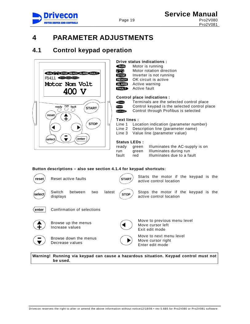
Drive status indications : RUN Motor is running
Motor rotation direction STOP Inverter is not running READY OK circuit is active ALARM Active warning FAULT Active fault
Control place indications :
I/O term Terminals are the selected control place Keypad Control keypad is the selected control place Bus/Comm Control through Profibus is selected Text lines : Line 1 Location indication (parameter number) Line 2 Description line (parameter name) Line 3 Value line (parameter value) Status LEDs : ready green Il luminates the AC-supply is on run green Il luminates during run
KeypadI/O term
READY FAULTSTOPRUN ALARM
Bus/CommP3.4.1.1.
Motor Nom Volt 400 V
START
STOP
enterselect
reset
ready run fault
fault red Il luminates due to a fault
Button descriptions – also see section 4.1.4 for ke ypad shortcuts:
reset
Reset active faults START
Starts the motor if the keypad is the active control location
select
Switch between two latest displays STOP
Stops the motor if the keypad is the active control location
enter Confirmation of selections
Browse up the menus Increase values
Move to prev ious menu level Move cursor left Exit edit mode
Browse down the menus Decrease values
Move to next menu level Move cursor right Enter edit mode
Warning! Running via keypad can cause a hazardous s ituation. Keypad control must not
be used.

Page 20
Service Manual Pro2V080 Pro2V081
Drivecon reserves the right to al ter or amend the above information wi thout notice12/18/06 • rev 5.6B5 for Pro2V080 or Pro2V081 software
4.1.1 Navigation on the control keypad The letters listed below will appear as the first character in the parameter address. This letter only describes the type of parameter you are viewing. It has no relationship as to where you are in the parameters. Parameter navigation is actually completely determined by the numbers and is not dependent upon the letter.
Letter front of the code number describes variable type B = Button G = Group N = Multimonitor T = Trip Counter C = Counter H = Fault History P = Parameter V = Value D = Data I = Info R = Reference E = Expander M = Menu Group S = System
READYSTOP
G3.
Parameters G1G9
READYSTOP
G4.
Monitoring G1G23
READYSTOP
G5.
Panel Control B1R2
READYSTOP
M6.
System Menu S1S8
READYSTOP
M7.
Active Faults F0
READYSTOP
M8.
Fault History H1Hxx
READYSTOP
G3.4.
Motor Parameters G1G7
READYSTOP
G3.4.1.
Motor Set 1 P1G23
READYSTOP
P3.4.1.1.
Motor Nom Volt 400 V
READYSTOP
V4.22.
Output Frequency 0.00 Hz
READYSTOP
B5.1.
Panel ControlOff
READYSTOP
S6.2.
ApplicationCrane
READYSTOP
H8.1.
57 ThermistorF T1T16
READYSTOP
Operation days 0
I/O term I/O term I/O term
I/O term
I/O term I/O term
I/O term I/O term
I/O term I/O term
I/O term I/O term I/O te rm I/O term
T8.1.1.
4.1.2 Value line editing
enter
Modechange
Acceptvalue
Editvalue
READYSTOP
P3.4.1.1.
Motor Nom Volt 400 V
I/O te rm
Warning! Changing parameter settings during running may cause a hazardous situation.
Parameter settings must not be changed during opera tion.

Page 21
Service Manual Pro2V080 Pro2V081
Drivecon reserves the right to al ter or amend the above information wi thout notice12/18/06 • rev 5.6B5 for Pro2V080 or Pro2V081 software
4.1.3 Passwords Parameter Name Description
Following passwords release the parameter locks. Level 1 Locked 0 Level 2 Start-up 26
P3.1.1 Password
Level 3 Engineering 768
4.1.4 Special button functions and shortcuts
Button Time delay Description
START
> 2 seconds Password level changes to Level 3 Engineering.
> 2 seconds Displays the sof tware version.
> 2 seconds Display changes straight to adequate autotuning parameter.
select
> 2 seconds Changes display straight to V4.22 Output Frequency.
reset
> 3 seconds Resets whole H8 Fault History when display in any level of H8 menu.
enter > 1 second Resets whole H8 Fault History when display in sublevel of H8 menu.

Page 22
Service Manual Pro2V080 Pro2V081
Drivecon reserves the right to al ter or amend the above information wi thout notice12/18/06 • rev 5.6B5 for Pro2V080 or Pro2V081 software
4.1.5 Monitoring Below is a l ist of the group 4 Monitoring parameters. For example, operation of analog and digital inputs can be verified with monitoring parameters. After power off and on the display returns to its default display at 4.23.1 which is the Multimonitor. G4 Monitoring Unit PW 1
G4.1 Parameter Backup Unit PW 1B4.1.1 Load Default Par 1B4.1.2 Save User Par 1B4.1.3 Load User Par 1
G4.1.4 Factory Default Unit PW 4B4.1.4.1 Save Default Par 4
G4.2 Analog I/O Unit PW 1V4.2.1 Ain1 Value V 1V4.2.2 Ain2 Value V 1V4.2.3 Aout1 Value mA 1V4.2.4 Aout2 Value V 1
G4.3 Relay Output Unit PW 1V4.3.1 ROB1 State 1V4.3.2 ROB2 State K7 1V4.3.3 ROC1 State 1V4.3.4 ROD1 State 1V4.3.5 ROE1 State 1V4.3.6 ROE2 State 1V4.3.7 ROE3 State 1
G4.4 Operate Counters Unit PW 2V4.4.1 Motor MWh MWh 2V4.4.2 Generator MWh MWh 2V4.4.3 Start Counter x 1k 2V4.4.4 MotorRuntime (h) h 2
G4.5 Fault Counter Unit PW 2V4.5.1 F1 Overcurrent 2V4.5.2 F2 Overvoltage 2V4.5.3 F3 Earth Fault 2V4.5.4 F7 Saturation 2V4.5.5 F9 Undervoltage 2V4.5.6 F10 Input Phase 2V4.5.7 F11 Output Phase 2V4.5.8 F12 BrakeChopper 2V4.5.9 F13 Undertemp 2V4.5.10 F14 Overtemp 2V4.5.12 F31 IGBT Temp HW 2V4.5.13 F41 IGBT Temp 2V4.5.14 F43 Encoder 2V4.5.15 F53 Profibus 2V4.5.16 F56 Gen Curr Lim 2V4.5.11 F57 Thermistor 2V4.5.17 F61 SSU Overspd 2V4.5.18 F62 SSU Spd Diff 2V4.5.19 F63 SSU Stall 2V4.5.20 F74 Sway Control 2V4.5.21 F76 Input Signal 2V4.5.22 A81 Brake Slip 2V4.5.23 A82 Overweight 2V4.5.24 Other faults 2V4.5.25 Total Faults 2
G4.6 Bus Control Unit PW 1V4.6.1 S1 Fieldbus 1V4.6.2 S2 Fieldbus 1V4.6.3 Motor Set 2 1V4.6.4 Second Speed Lim 1V4.6.5 Field Weakening 1V4.6.6 Alt Control Mode 1V4.6.7 Brake Feedback 1V4.6.8 Ramp 2 1V4.6.9 Torque Limit 1V4.6.10 AP 1V4.6.11 Slow Limit S11 1V4.6.12 Slow Limit S21 1V4.6.13 End Limit S12 1V4.6.14 End Limit S22 1V4.6.15 Brake Pedal 1V4.6.16 S-Curve Inhibit 1V4.6.17 Tare 1V4.6.18 Inching 1V4.6.19 SlackCableBypass 1V4.6.20 Brake Pedal 2 1V4.6.21 Synchronizing 1V4.6.22 Speed Reference Hz 1V4.6.23 Torque Reference % 1V4.6.24 Speed Correction Hz 1V4.6.25 Ramp Reference 1V4.6.26 Torgue Limit Ref % 1V4.6.27 Speed Limit Ref 1V4.6.28 Load Feedback 1V4.6.29 Sway Ctrl Height 1V4.6.30 Calibration Pos 1V4.6.31 Profibus Status 1V4.6.32 Bus Cycle Time ms 1
G4.7 Digital Input Unit PW 1G4.7.1 DI Status Unit PW 1
V4.7.1.1 S1 1V4.7.1.2 S2 1V4.7.1.3 DIA3 1V4.7.1.4 DIA4 1V4.7.1.5 DIA5 1V4.7.1.6 OK 1V4.7.1.7 DID1 1V4.7.1.8 DID2 1V4.7.1.9 DID3 1V4.7.1.10 DID4 1V4.7.1.11 DID5 1
G4.7.2 DI Functions Unit PW 1V4.7.2.1 DIA3 Function 1V4.7.2.2 DIA4 Function 1V4.7.2.3 DIA5 Function 1V4.7.2.4 DID1 Function 1V4.7.2.5 DID2 Function 1V4.7.2.6 DID3 Function 1V4.7.2.7 DID4 Function 1V4.7.2.8 DID5 Function 1
V4.7.3 Basic Board 1V4.7.4 Extension Board 1
G4.8 SSU Unit PW 1V4.8.1 Overspd Lim 1 % 1V4.8.2 Overspd Lim 2 % 1
G4.9 Service Unit PW 3V4.9.1 Phase U Curr A 3V4.9.2 Phase V Curr A 3V4.9.3 Phase W Curr A 3V4.9.4 Encoder Speed Hz 3V4.9.5 HeatSinkTempMax °C 3V4.9.6 HeatSinkTempMin °C 3V4.9.7 IGBT Temp Max °C 3V4.9.8 IGBT Temperature °C 3V4.9.9 SlipAdjustChange % 3
G4.9.10 Max Current Unit PW 3V4.9.10.1 Max Current 3V4.9.10.2 Max Current Freq 3V4.9.10.3 Max Current Torq 3
G4.10 Sway Control Unit PW 3V4.10.1 Swing Time s 3V4.10.2 Pendulum Length m 3V4.10.3 StoppingDistance m 3V4.10.4 Sway Ctrl Status 3V4.10.5 License Status 3V4.10.6 DemoLicenseTime 3
V4.11 Freq Ref Hz 1V4.12 Speed Req Hz 1V4.13 Distance Counter m 1V4.14 DC-link Voltage V 1V4.15 Heat Sink Temp °C 1V4.16 MotorTemperature % 1V4.17 Motor Power % 1V4.18 Motor Voltage V 1V4.19 Motor Torque % 1V4.20 Motor Current A 1V4.21 Motor Speed rpm 1V4.22 Output Frequency Hz 1
G4.23 Multimonitor Unit PW 1V4.23.1 Multimonitor 1

Page 23
Service Manual Pro2V080 Pro2V081
Drivecon reserves the right to al ter or amend the above information wi thout notice12/18/06 • rev 5.6B5 for Pro2V080 or Pro2V081 software
4.2 Input selections Digital inputs are programmed based on function. Each function can be set to one of the 8 programmable digital inputs. The programmable digital inputs are DIA3, DIA4, DIA5, DID1, DID2, DID3, DID4 or DID5. Some functions can be set always ON or always OFF to activate certain functions permanently. There are also 3 other inputs, which functions can not be changed by parameters. These non-programmable inputs are OK-input and the direction signals S1 (up or forward) and S2 (down or reverse). In basic applications one function is set to each input. For special applications it is also possible to set many functions to same input. For example the Torque limit and Ramp2 should be activated with DIA5. Select the value 3=DIA5 in both parameters P3.2.1.7 and P3.2.1.8. Note! Impossible function combinations may be selec ted. The following table lists the possible inputs for each function. Parameter Name / Function DIA3 DIA4 DIA5 DID1 DID2 DID3 DID4 DID5 ON OFF P3.2.1.1 Motor Set 2 X X X X X X X X X X P3.2.1.2 SSL X X X X X X X X X X P3.2.1.3 ESR X X X X X X X X X X P3.2.1.4 Micro Speed Sel X X X X X X X X X X P3.2.1.5 Alt Control Sel X X X X X X X X X X P3.2.1.6 Profibus Control - - X - - - - - - - P3.2.1.7 Ramp2 X X X X X X X X X X P3.2.1.8 Trq Limit X X X X X X X X X X P3.2.1.9 AP X - - - - - - - X X P3.2.1.10 CMS - X - - - - - - X X P3.2.1.11 EP-Hold X X X X X X X X - - P3.2.1.12 Mult istep2 X X - - - - - - - - P3.2.1.13 Mult istep3 - X X - - - - - - - P3.2.1.14 Mult istep4 - - X X - - - - - - P3.2.1.15 Mult istep5 - - - X X - - - - - P3.2.1.16 PO/MS X X X X X X X X - - P3.2.1.17 S11 - - X - X - - - X X P3.2.1.18 S21 - - - X - X - - X X P3.2.1.19 S11 & S21 X X X X X X X X - - P3.2.1.20 S12 - - - - X - X - - - P3.2.1.21 S22 - - - - - X - X - - P3.2.1.22 MF1 Input X X X X X X X X - - P3.2.1.24 MF2 Input X X X X X X X X - -

Page 24
Service Manual Pro2V080 Pro2V081
Drivecon reserves the right to al ter or amend the above information wi thout notice12/18/06 • rev 5.6B5 for Pro2V080 or Pro2V081 software
4.3 Speed supervision settings SSU is a hoist motion speed supervision unit, which reads the pulse frequency from the hoist motor bearing sensor, encoder, or pulse sensor. This pulse frequency is compared with a fixed oscil lator frequency and drive frequency reference. As a result of the frequency comparison, there are three different speed supervision functions available:
- overspeed superv ision (rush control) - stall superv ision - speed difference supervision
Overspeed supervision (F61) is totally implemented by hardware. Switches S2-2 and S2-3 div ide the full frequency range to four frequency areas.
- Selected frequency area is the same for normal and ESR speeds. The four frequency areas are each div ided to lower and upper frequency ranges
- Switch S2-1 selects the frequency range at normal speed. - Switch S2-4 selects the frequency range at ESR speed (Extended Speed
Range). The exact tripping frequency level is selected with rotary switches.
- Switch S1 sets the tripping level at normal speed (value shown in V4.8.1). - Switch S3 sets the tripping level at ESR speed (value shown in V4.8.2).
Overspeed tripping levels are shown at display as % of the motor nominal speed. The overspeed setting should be 15-25% above the nominal speed. Speed difference supervision (F62) compares the motor actual speed (= pulse frequency) with frequency reference. In practice this means that the motor slip is measured and if that exceeds a preset l imit, supervision stops the motion. Allowed speed difference (%) is adjusted with parameter P3.3.10.1. The use of ESR has no effect on this parameter setting. Stall supervision (F63) stops the motion if there are no pulses coming from the sensor when the brake is open (K7 energized). Allowed time (s) without pulses before a fault is detected is adjusted with parameter P3.3.10.2. SSU relay test (F64): SSU relay is tested each time the drive powers up. Operation is prevented if a fault has been detected. SSU Watchdog fault (F65): Communication between SSU board and control board is tested once every 50ms. A fault will be detected if there is communication error. When a fault is detected operation is prevented. SSU Overspeed Limit (F66): Maximum setting of the overspeed limit is 1.4*nominal speed of direction S2 (normal and ESR). Fault will be detected if the overspeed l imit is set higher than that value. When a fault is detected, operation is prevented. Brake Slip (A84): Active only when the parameters have been programmed for this detection. See section 4.6 of this manual for further information about this feature.
1 2 3 4
ON OFF
S1
S2
S3

Page 25
Service Manual Pro2V080 Pro2V081
Drivecon reserves the right to al ter or amend the above information wi thout notice12/18/06 • rev 5.6B5 for Pro2V080 or Pro2V081 software
Standard settings As an aid to determine proper settings, these tables indicate the pulse frequencies and the correct switch settings for standard cases with certain combinations of motor speed and pulses per revolution. Open loop Proximity switch Bearing sensor
Motor RPM 3600 3000 1800 1500 3600 3000 3600 3000 3600 3000 Pulse number 24 24 24 24 32 32 64 64 80 80 Pulse frequency 1440 1200 720 600 1920 1600 3840 3200 4800 4000 Rotary switch S1, S3 7 4 E B 1 F A 8 D B Switch S2-1, S2-4 ON ON OFF OFF ON OFF ON ON ON ON Switch S2-2 ON ON ON ON OFF OFF OFF OFF OFF OFF Switch S2-3 OFF OFF OFF OFF OFF OFF OFF OFF OFF OFF Closed loop Encoder
Motor RPM 3600 3000 1800 1500 1200 1000 Pulse number 600 600 600 600 600 600 Pulse frequency 36000 30000 18000 15000 12000 10000 Rotary switch S1, S3 4 1 B 8 5 3 Switch S2-1, S2-4 ON ON OFF OFF OFF OFF Switch S2-2 ON ON ON ON ON ON Switch S2-3 ON ON ON ON ON ON
Overspeed tripping frequency levels Area selection 300 – 3234 Hz 600 – 6467Hz 1200 – 12 935Hz 9600 – 70722Hz S2:2 ON OFF OFF ON S2:3 OFF OFF ON ON Range selection Normal S2:1 OFF ON OFF ON OFF ON OFF ON
0 300 1027 600 2055 1200 4110 9600 32878 1 324 1109 647 2218 1295 4436 10359 35489 2 350 1195 700 2391 1400 4781 11196 38251 3 378 1291 756 2582 1511 5163 12092 41304 4 408 1396 816 2793 1632 5585 13055 44684 5 441 1506 881 3012 1763 6024 14104 48188 6 476 1625 951 3251 1902 6502 15217 52013 7 514 1755 1027 3511 2055 7022 16439 56174 8 555 1896 1109 3793 2218 7585 17744 60681 9 599 2048 1198 4096 2395 8192 19163 65536 A 647 2210 1296 4420 2587 8840 20696 70722 B 698 2381 1396 4763 2793 9526 22342 -- C 755 2586 1510 5163 3019 10326 24153 -- D 815 2793 1630 5585 3259 11171 26075 -- E 880 3012 1760 6024 3521 12047 28167 --
S1/Normal
Tripping level
selection
S3/ESR
F 951 3234 1902 6467 3804 12935 30435 ESR S2:4 Range selection
OFF ON OFF ON OFF ON OFF ON
S2:1 together with S1 is used for setting the tripping frequency level at normal speed. S2:4 together with S3 is used for setting the tripping frequency level at ESR speed. If ESR is not used, set S2:4 + S3 equal to S2:1 and S1.
Page 26
Service Manual Pro2V080 Pro2V081
Drivecon reserves the right to al ter or amend the above information wi thout notice12/18/06 • rev 5.6B5 for Pro2V080 or Pro2V081 software
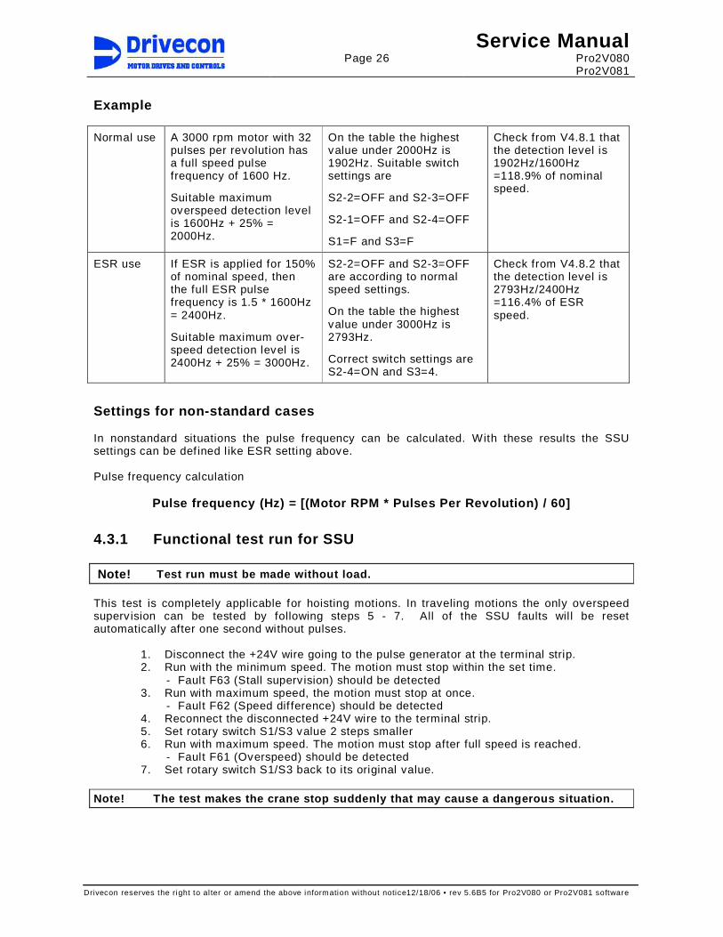
Example
Normal use A 3000 rpm motor with 32 pulses per revolution has a full speed pulse frequency of 1600 Hz.
Suitable maximum overspeed detection level is 1600Hz + 25% = 2000Hz.
On the table the highest value under 2000Hz is 1902Hz. Suitable switch settings are
S2-2=OFF and S2-3=OFF
S2-1=OFF and S2-4=OFF
S1=F and S3=F
Check from V4.8.1 that the detection level is 1902Hz/1600Hz =118.9% of nominal speed.
ESR use If ESR is applied for 150% of nominal speed, then the full ESR pulse frequency is 1.5 * 1600Hz = 2400Hz.
Suitable maximum over-speed detection level is 2400Hz + 25% = 3000Hz.
S2-2=OFF and S2-3=OFF are according to normal speed settings.
On the table the highest value under 3000Hz is 2793Hz.
Correct switch settings are S2-4=ON and S3=4.
Check from V4.8.2 that the detection level is 2793Hz/2400Hz =116.4% of ESR speed.
Settings for non-standard cases In nonstandard situations the pulse frequency can be calculated. With these results the SSU settings can be def ined l ike ESR setting above. Pulse frequency calculation
Pulse frequency (Hz) = [(Motor RPM * Pulses Per Revolution) / 60]
4.3.1 Functional test run for SSU
Note! Test run must be made without load. This test is completely applicable for hoisting motions. In traveling motions the only overspeed superv ision can be tested by following steps 5 - 7. All of the SSU faults wil l be reset automatically after one second without pulses.
1. Disconnect the +24V wire going to the pulse generator at the terminal strip. 2. Run with the minimum speed. The motion must stop within the set time.
- Fault F63 (Stall superv ision) should be detected 3. Run with maximum speed, the motion must stop at once.
- Fault F62 (Speed dif ference) should be detected 4. Reconnect the disconnected +24V wire to the terminal strip. 5. Set rotary switch S1/S3 value 2 steps smaller 6. Run with maximum speed. The motion must stop after full speed is reached.
- Fault F61 (Overspeed) should be detected 7. Set rotary switch S1/S3 back to its original value.
Note! The test makes the crane stop suddenly that m ay cause a dangerous situation.
Page 27
Service Manual Pro2V080 Pro2V081
Drivecon reserves the right to al ter or amend the above information wi thout notice12/18/06 • rev 5.6B5 for Pro2V080 or Pro2V081 software
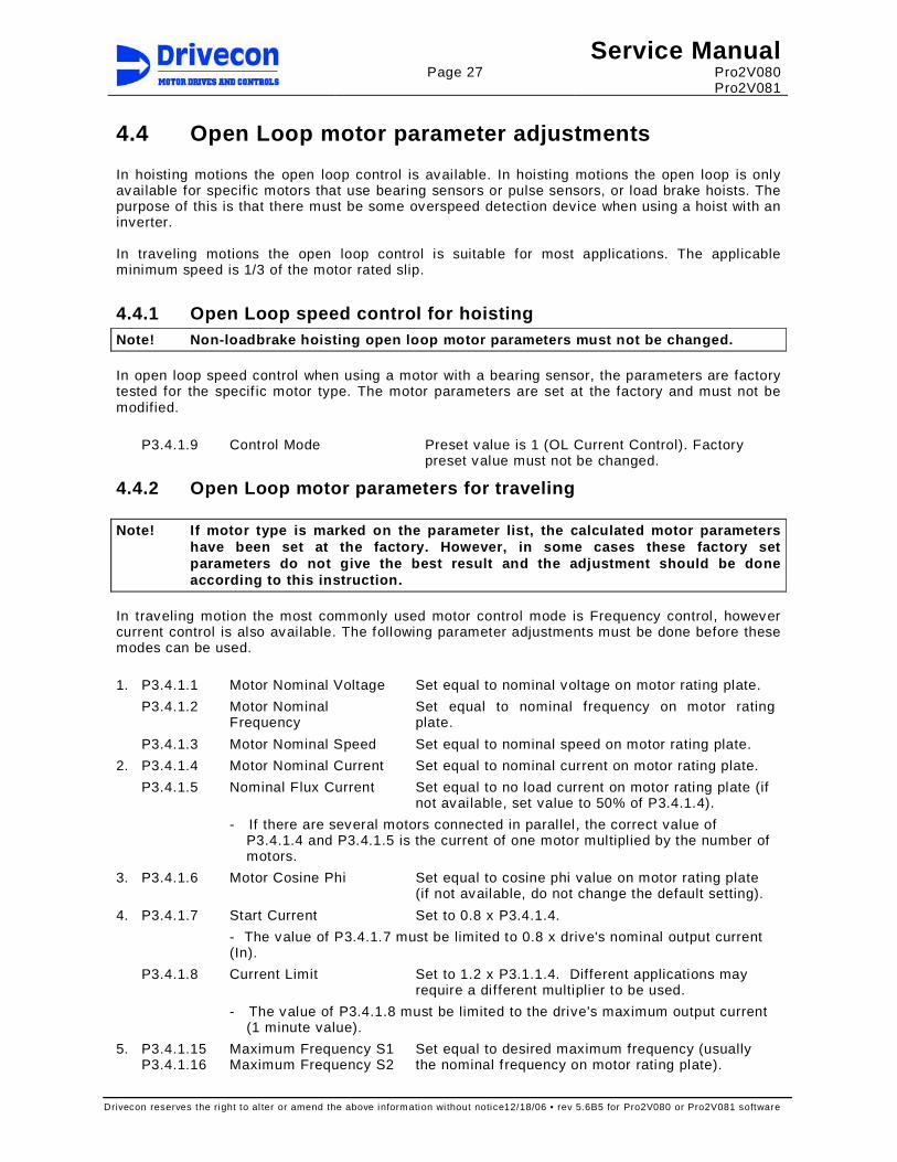
4.4 Open Loop motor parameter adjustments In hoisting motions the open loop control is available. In hoisting motions the open loop is only available for specific motors that use bearing sensors or pulse sensors, or load brake hoists. The purpose of this is that there must be some overspeed detection device when using a hoist with an inverter. In traveling motions the open loop control is suitable for most applications. The applicable minimum speed is 1/3 of the motor rated slip.
4.4.1 Open Loop speed control for hoisting Note! Non-loadbrake hoisting open loop motor parame ters must not be changed. In open loop speed control when using a motor with a bearing sensor, the parameters are factory tested for the specif ic motor type. The motor parameters are set at the factory and must not be modified.
P3.4.1.9 Control Mode Preset value is 1 (OL Current Control). Factory preset value must not be changed.
4.4.2 Open Loop motor parameters for traveling Note! If motor type is marked on the parameter list , the calculated motor parameters
have been set at the factory. However, in some case s these factory set parameters do not give the best result and the adju stment should be done according to this instruction.
In traveling motion the most commonly used motor control mode is Frequency control, however current control is also available. The following parameter adjustments must be done before these modes can be used.
1. P3.4.1.1 Motor Nominal Voltage Set equal to nominal voltage on motor rating plate.
P3.4.1.2 Motor Nominal Frequency
Set equal to nominal frequency on motor rating plate.
P3.4.1.3 Motor Nominal Speed Set equal to nominal speed on motor rating plate.
2. P3.4.1.4 Motor Nominal Current Set equal to nominal current on motor rating plate.
P3.4.1.5 Nominal Flux Current Set equal to no load current on motor rating plate (if not available, set value to 50% of P3.4.1.4).
- If there are several motors connected in parallel, the correct value of P3.4.1.4 and P3.4.1.5 is the current of one motor multipl ied by the number of motors.
3. P3.4.1.6 Motor Cosine Phi Set equal to cosine phi value on motor rating plate (if not available, do not change the default setting).
4. P3.4.1.7 Start Current Set to 0.8 x P3.4.1.4.
- The value of P3.4.1.7 must be limited to 0.8 x drive's nominal output current (In).
P3.4.1.8 Current Limit Set to 1.2 x P3.1.1.4. Different applications may require a different multiplier to be used.
- The value of P3.4.1.8 must be limited to the drive's maximum output current (1 minute value).
5. P3.4.1.15 P3.4.1.16
Maximum Frequency S1 Maximum Frequency S2
Set equal to desired maximum frequency (usually the nominal f requency on motor rating plate).
Page 28
Service Manual Pro2V080 Pro2V081
Drivecon reserves the right to al ter or amend the above information wi thout notice12/18/06 • rev 5.6B5 for Pro2V080 or Pro2V081 software
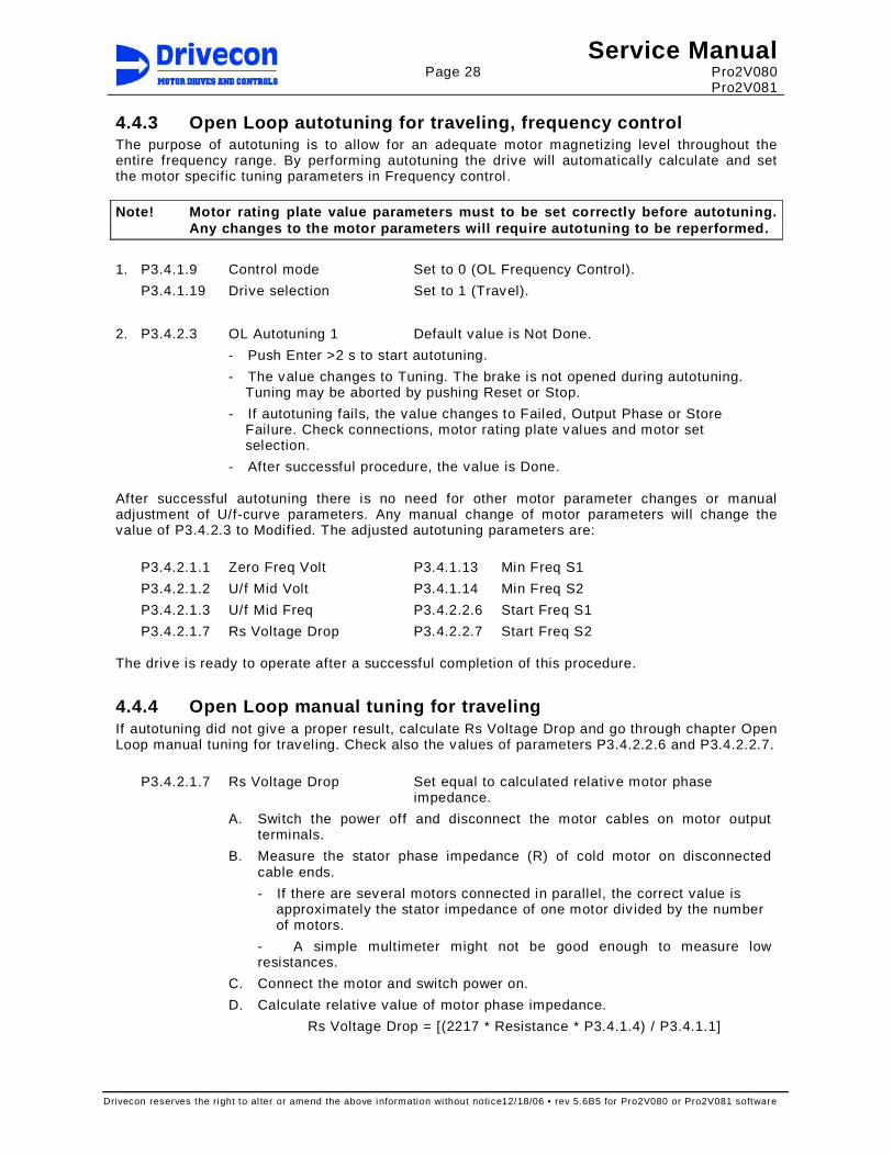
4.4.3 Open Loop autotuning for traveling, frequency control The purpose of autotuning is to allow for an adequate motor magnetizing level throughout the entire frequency range. By performing autotuning the drive will automatically calculate and set the motor specific tuning parameters in Frequency control. Note! Motor rating plate value parameters must to b e set correctly before autotuning.
Any changes to the motor parameters will require au totuning to be reperformed.
1. P3.4.1.9 Control mode Set to 0 (OL Frequency Control).
P3.4.1.19 Drive selection Set to 1 (Travel).
2. P3.4.2.3 OL Autotuning 1 Default value is Not Done.
- Push Enter >2 s to start autotuning.
- The value changes to Tuning. The brake is not opened during autotuning. Tuning may be aborted by pushing Reset or Stop.
- If autotuning fails, the value changes to Failed, Output Phase or Store Failure. Check connections, motor rating plate values and motor set selection.
- After successful procedure, the value is Done. After successful autotuning there is no need for other motor parameter changes or manual adjustment of U/f-curve parameters. Any manual change of motor parameters will change the value of P3.4.2.3 to Modified. The adjusted autotuning parameters are:
P3.4.2.1.1 Zero Freq Volt P3.4.1.13 Min Freq S1
P3.4.2.1.2 U/f Mid Volt P3.4.1.14 Min Freq S2
P3.4.2.1.3 U/f Mid Freq P3.4.2.2.6 Start Freq S1
P3.4.2.1.7 Rs Voltage Drop P3.4.2.2.7 Start Freq S2 The drive is ready to operate after a successful completion of this procedure.
4.4.4 Open Loop manual tuning for traveling If autotuning did not give a proper result, calculate Rs Voltage Drop and go through chapter Open Loop manual tuning for traveling. Check also the values of parameters P3.4.2.2.6 and P3.4.2.2.7.
P3.4.2.1.7 Rs Voltage Drop Set equal to calculated relative motor phase impedance.
A. Switch the power off and disconnect the motor cables on motor output terminals.
B. Measure the stator phase impedance (R) of cold motor on disconnected cable ends.
- If there are several motors connected in parallel, the correct value is approximately the stator impedance of one motor div ided by the number of motors.
- A simple multimeter might not be good enough to measure low resistances.
C. Connect the motor and switch power on.
D. Calculate relative value of motor phase impedance.
Rs Voltage Drop = [(2217 * Resistance * P3.4.1.4) / P3.4.1.1]

Page 29
Service Manual Pro2V080 Pro2V081
Drivecon reserves the right to al ter or amend the above information wi thout notice12/18/06 • rev 5.6B5 for Pro2V080 or Pro2V081 software
4.4.5 Open Loop manual tuning for traveling, freque ncy control The default motor control mode is Frequency control. Frequency control is used to get optimal magnetizing current to the motor by util izing U/f-curve tuning. When using Frequency control this guarantees good low and middle speed characteristics. The following table shows the formulas to calculate the values f rom where to start the tuning.
P3.4.2.1.1
Zero Frequency Voltage (%)
P3.4.2.1.2
U/f Midpoint Voltage (%)
P3.4.2.1.3
U/f Midpoint Frequency (Hz)
[(100 * Resistance * P3.4.1.5) / P3.4.1.1] 1.41 * P3.4.2.1.1 (P3.4.2.1.1 * P3.4.1.2) / 100
1. P3.4.1.9 Control Mode Set to 0 (OL Frequency Control).
2. P3.4.1.13 P3.4.1.14
Minimum Frequency S1 Minimum Frequency S2
Set equal to P3.4.2.1.3 (U/f Midpoint Frequency).
A. Run at maximum speed and check the motor current value (V4.20).
B. Try to run at minimum speed and check the motor current value. Motor current at minimum speed should be approximately average of the prev iously measured maximum speed current and the rated current.
P3.4.2.1.2 C. Increase or decrease value to increase or decrease motor current. Run again minimum speed and check motor current. Repeat step B unti l current value is within the desired range.
3. P3.4.1.13 P3.4.1.14
Minimum Frequency S1 Minimum Frequency S2
Set equal to P3.4.2.1.3 div ided by 2.
A. Try to run at minimum speed and check the motor current value. It must be approximately average of the previously measured maximum speed current and rated current.
P3.4.2.1.1 B. Increase or decrease value to increase or decrease motor current. Run again minimum speed and check motor current. Repeat step A unti l current value is within the desired range. The motor might not run if the frequency is very low.
4. P3.4.1.13 P3.4.1.14
Minimum Frequency S1 Minimum Frequency S2
Set according to desired minimum speed
A. If the motor is not running at minimum speed, increase parameters and continue from step 1.
The drive is ready to operate after a successful completion of this procedure.
4.4.6 Open Loop manual tuning for traveling, curren t control Current control can be used instead of frequency control according to following rules. - Motor nominal current must not be higher than drive’s rated current. - The number of connected motors must not be variable.
1. P3.4.1.9 Control Mode Set to 1 (OL Current Control).
2. P3.4.1.5 Nominal Flux Current If the rating plate value was not available, a proper value can be found by test run.
A. Make sure that the crane has no load on the hook.
B. Run on maximum speed and read the current on the keypad display (V4.20).
The drive is ready to operate after these adjustments.

Page 30
Service Manual Pro2V080 Pro2V081
Drivecon reserves the right to al ter or amend the above information wi thout notice12/18/06 • rev 5.6B5 for Pro2V080 or Pro2V081 software
4.5 Closed Loop motor parameter adjustments Closed loop control is available for all power ratings. Motors for these applications must have an incremental encoder mounted directly on the motor shaf t for speed feedback. Normally the incremental encoder has 600 pulses per revolution. In special applications, l ike modernization, it is possible to use 512, 1000, 1024, 1200, 2000 or 2048 pulses per revolution encoders also. Speed accuracy is better than with open loop control modes and thus fine positioning is accurate. In traveling motions closed loop requires the SSU board in the inverter and closed loop is used only in special cases when the speed accuracy demands are high. Note! The closed loop parameters must always be set in start-up.
4.5.1 Closed Loop rated motor parameters
Before running
In closed loop speed control, the parameters must always be set during commissioning. The following parameter adjustments must be performed before this modes can be used.
1. P3.4.1.1 Motor Nominal Voltage Set equal to nominal voltage on motor rating plate.
P3.4.1.2 Motor Nominal Frequency
Set equal to nominal frequency on motor rating plate.
P3.4.1.3 Motor Nominal Speed Set equal to nominal speed on motor rating plate.
2. P3.4.1.4 Motor Nominal Current Set equal to nominal current on motor rating plate.
P3.4.1.5 Nominal Flux Current Set equal to no load current on motor rating plate (if not available, set value to 50%).
- If there are several motors connected in parallel, the correct value of P3.4.1.4 and P3.4.1.5 is the current of one motor multipl ied by the number of motors.
3. P3.4.1.6 Motor Cosine Phi Set equal to cosine phi value on motor rating plate.
4. P3.4.1.7 Start Current Set to 1.0 x P3.4.1.4. Different applications may require a different multiplier to be used.
- The value of P3.4.1.7 must be limited to drive’s nominal output current (In).
P3.4.1.8 Current Limit Set to 1.2 x P3.1.1.4. Different applications may require a different multiplier to be used.
- The value of P3.4.1.8 must be limited to drive’s maximum output current (1 minute value).
5. P3.4.1.15 P3.4.1.16
Maximum Frequency S1 Maximum Frequency S2
Set equal to desired maximum frequency (usually the nominal f requency on motor rating plate).
6. P3.4.1.9 Control Mode Verify the value is 3 (CL Speed Control). Note! Check the operation of limit switches before performing closed loop tuning.
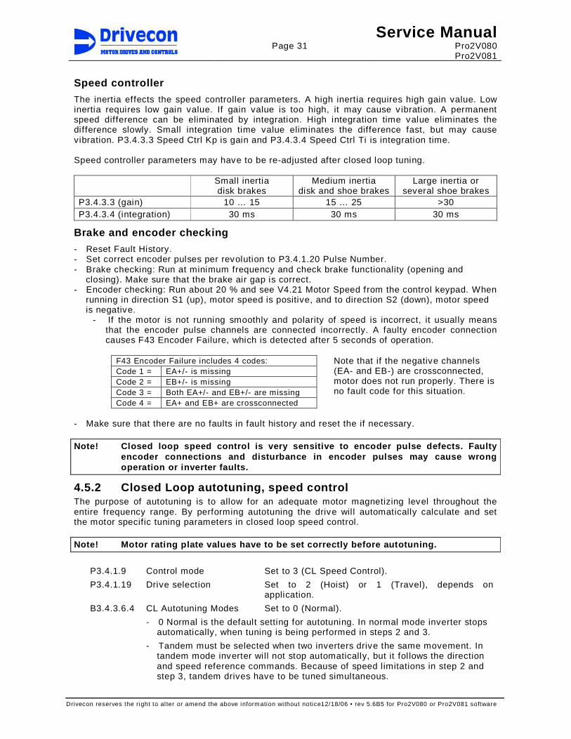
Page 31
Service Manual Pro2V080 Pro2V081
Drivecon reserves the right to al ter or amend the above information wi thout notice12/18/06 • rev 5.6B5 for Pro2V080 or Pro2V081 software
Speed controller
The inertia effects the speed controller parameters. A high inertia requires high gain value. Low inertia requires low gain value. If gain value is too high, it may cause v ibration. A permanent speed difference can be eliminated by integration. High integration time value eliminates the difference slowly. Small integration time value eliminates the difference fast, but may cause vibration. P3.4.3.3 Speed Ctrl Kp is gain and P3.4.3.4 Speed Ctrl Ti is integration time. Speed controller parameters may have to be re-adjusted after closed loop tuning.
Small inertia disk brakes
Medium inertia disk and shoe brakes
Large inertia or several shoe brakes
P3.4.3.3 (gain) 10 … 15 15 … 25 >30 P3.4.3.4 (integration) 30 ms 30 ms 30 ms
Brake and encoder checking
- Reset Fault History. - Set correct encoder pulses per revolution to P3.4.1.20 Pulse Number. - Brake checking: Run at minimum frequency and check brake functionality (opening and
closing). Make sure that the brake air gap is correct. - Encoder checking: Run about 20 % and see V4.21 Motor Speed f rom the control keypad. When
running in direction S1 (up), motor speed is positive, and to direction S2 (down), motor speed is negative.
- If the motor is not running smoothly and polarity of speed is incorrect, it usually means that the encoder pulse channels are connected incorrectly. A faulty encoder connection causes F43 Encoder Failure, which is detected after 5 seconds of operation.
F43 Encoder Failure includes 4 codes: Code 1 = EA+/- is missing Code 2 = EB+/- is missing Code 3 = Both EA+/- and EB+/- are missing Code 4 = EA+ and EB+ are crossconnected
Note that if the negative channels (EA- and EB-) are crossconnected, motor does not run properly. There is no fault code for this situation.
- Make sure that there are no faults in fault history and reset the if necessary. Note! Closed loop speed control is very sensitive t o encoder pulse defects. Faulty
encoder connections and disturbance in encoder puls es may cause wrong operation or inverter faults.
4.5.2 Closed Loop autotuning, speed control The purpose of autotuning is to allow for an adequate motor magnetizing level throughout the entire frequency range. By performing autotuning the drive wil l automatically calculate and set the motor specific tuning parameters in closed loop speed control. Note! Motor rating plate values have to be set corr ectly before autotuning.
P3.4.1.9 Control mode Set to 3 (CL Speed Control).
P3.4.1.19 Drive selection Set to 2 (Hoist) or 1 (Travel), depends on application.
B3.4.3.6.4 CL Autotuning Modes Set to 0 (Normal).
- 0 Normal is the default setting for autotuning. In normal mode inverter stops automatically, when tuning is being performed in steps 2 and 3.
- Tandem must be selected when two inverters drive the same movement. In tandem mode inverter will not stop automatically, but it fol lows the direction and speed reference commands. Because of speed l imitations in step 2 and step 3, tandem drives have to be tuned simultaneous.

Page 32
Service Manual Pro2V080 Pro2V081
Drivecon reserves the right to al ter or amend the above information wi thout notice12/18/06 • rev 5.6B5 for Pro2V080 or Pro2V081 software
Note! Steps 1 and 2 of closed loop autotuning must be done with empty hook and without any loading devices. In the steps 2 and 3 the motor will need to be operated. The display will show how the motor need s to be run; it will not run automatically.
CL autotuning step 1 –Static tuning, the brake will not be controlled to open
P3.4.3.6.1 CLAutotune1step1
Slip Adjust pre-tuning
- Push Enter >2 s to start autotuning step 1.
- The value changes to Tuning. The brake is not opened during CL autotuning step 1. Tuning may be aborted by pushing Reset or Stop button.
- If autotuning fails, check instructions from troubleshooting section.
- After successful procedure, the value is “Done.”
- Adjusted parameter in autotuning step 1 is P3.4.3.1 Slip Adjust.
- Check value of P3.4.3.1 Slip Adjust. If the value is very close to 200, reset the value to 70 and continue to autotuning step 2.
CL autotuning step 2 –dynamic tuning, run the motor without load on crane
P3.4.3.6.2 CLAutotune1step2
Flux Current and Brake Control tuning
- Push Enter >2 s to start autotuning step 2.
- Brake wil l open during step 2.
- Follow instructions from the inverter display.
- Drive upwards or forwards (dir 1) and accelerate straight to full speed.
- Inverter stops driv ing and restarts once.
- If autotuning fails, check instructions from troubleshooting section.
- After successful procedure, the value is “Done.”
- Any manual change of flux current parameter changes value to Modified.
- Adjusted parameters in autotuning step 2 are P3.4.1.5 Nom Flux Curr, P3.4.3.5.4 Brk Opening Del and P3.4.3.5.5 Start Magn Time.
CL autotuning step 3 –dynamic tuning, run the motor with 75-125% load on crane
P3.4.3.6.3 CLAutotune1step3
Slip Adjust fine-tuning
- Push Enter >2 s to start autotuning step 3.
- Brake wil l open during step 3.
- Follow instructions from the inverter display.
- Drive upwards or forwards (dir 1), accelerate straight to full speed and stop driving.
- Fine-tuning may require several driv ing operations.
- If autotuning fails, check instructions from troubleshooting section.
- After successful completion, the value is “Done.”
- Any manual change of Slip Adjust parameter wil l change the value to Modified.
- Adjusted parameters in autotuning step 3 are P3.4.3.1 Slip Adjust and P3.3.14.1 Accel Torque.

Page 33
Service Manual Pro2V080 Pro2V081
Drivecon reserves the right to al ter or amend the above information wi thout notice12/18/06 • rev 5.6B5 for Pro2V080 or Pro2V081 software
After successful autotuning there is no need to make any other motor parameter changes or manual tuning of Closed Loop. The adjusted parameters in CL Autotuning are:
P3.4.1.5 Nom Flux Curr P3.4.3.5.4 Brk Opening Del
P3.4.3.1 Slip Adjust P3.4.3.5.5 Start Magn Time
P3.3.14.1 Accel Torque Drive is ready to operate after these adjustments. If there is any v ibration, fine adjustments of speed controller parameters may improve the operation.
Closed Loop autotuning troubleshooting
Step Fault Checking
Step 1 Brake failure - encoder is giving pulses => the brake is sl ipping - check brake adjustment
Output phase failure - the current is not flowing in all three phases - check motor cable connections
Failed - Autotuning failed - check chapter 4.5.1 Closed Loop rated motor
parameters Step 2 Load too high - calculated motor torque too high (>30%)
- decrease the load Flux current fault - tuning of motor flux current was not successful
- original value of P3.4.1.5 Nom Flux Curr is wrong - check motor rating plate value
Speed failure - inverter can not accelerate to 64 % of nominal speed with normal ramp
- check P3.4.1.15 Max Freq S1 is correct - check that there is no mechanical barriers
Brake detect fault - brake opening not OK - general fault during brake opening - wrong current limit values or motor parameters
Any fault code
- in case of any fault code, if no reason found, change P3.4.3.1 Slip Adjust to 70 (default) and try CL autotuning step 2 again
Step 3 Load too small - inertia of machinery is too small - test load needed between 75-125%
Slip adjust fault - inverter was not able to tune Slip Adjust properly in 10 attempts
- Slip Adjust value does not change and differs over 1% of original Slip adjust value
- original value of P3.4.3.1 Slip Adjust is wrong - change P3.4.3.1 Slip Adjust to 70 (default) and try
again CL autotuning step 1 Failed - try again Steps 1 - 3 Store failure - writing to EEPROM failed Failed - reset or stop
- general fault in inverter - motor set change during tuning - incorrect operation based on keypad instructions
After troubleshooting the failure, restart the autotuning from the lowest step that has value “Not Done” or “Failed.” If autotuning does not give a proper result, go through chapter 4.5.3 Closed Loop manual tuning for hoisting, speed control. In case of traveling motion, contact factory for more information.

Page 34
Service Manual Pro2V080 Pro2V081
Drivecon reserves the right to al ter or amend the above information wi thout notice12/18/06 • rev 5.6B5 for Pro2V080 or Pro2V081 software
4.5.3 Closed Loop manual tuning for hoisting, speed control If autotuning could not be completed or did not give a satisfactory result, go through the following closed loop manual tuning for hoisting.
Motor nominal flux current (no load current) measur ement
This procedure must be done when there is no information of motor no load current in the motor rating plate. The measured no load current must be set to P3.4.1.5 Motor Nom Flux Current. The motor nominal flux current is the current motor is taking in constant speed and without any torque boost and U/f-curve adjustments. - Set P3.4.1.9 Control Mode = 0 (Open Loop Freq Control). - Set P3.4.2.1.1 Zero Freq Volt, P3.4.2.1.2 U/f Mid Volt, P3.4.2.1.3 U/f Mid Freq to zero and
P3.4.2.1.4 Torque Boost = 0 (OFF) in G3.4.2.1 U/f - curve. - Run without any load in the hook 75% of nominal f requency of the motor. Fil l the values of
V4.18 Motor Voltage, V4.22 Output Frequency, V4.19 Motor Torque and V4.20 Motor Current in the closed loop start-up table.
- Set the measured motor no load current to P3.4.1.5 Motor Nom Flux Current. - Set P3.4.1.9 Control Mode = 3 (Closed Loop Speed Control).
Closed Loop test run without load
- Make sure that P3.4.1.9 Control Mode = 3 (Closed Loop Speed Control). - Make sure that the U/f-curve is between lower and upper limit voltage. Run without load
upwards at 75% of the nominal frequency. a) If voltage is lower than lower l imit => increase value of P3.4.1.5 Motor Nom Flux
Current. b) If voltage is higher than upper limit => decrease value of P3.4.1.5 Motor Nom Flux
Current. - After possible changes of P3.4.1.5 Motor Nom Flux Current, run 75 % of nominal speed. Fill
the values of V4.18 Motor Voltage, V4.22 Output Frequency, V4.19 Motor Torque and V4.20 Motor Current in the closed loop start-up table.
Below are test frequencies and voltage ranges for V4.18 Motor Voltage. Frequency is 75% of nominal and voltage 76 % of nominal +10V window. Adjusted U/f-curve must be between Lower Limit Voltage and Upper Limit Voltage in closed loop test without load and with load when running upwards. Motor Nom Freq 50 Hz 60 Hz 100 Hz 120 Hz P3.4.1.15 Max Freq S1 37.5 45 75 90 Motor Nom Voltage 380 V 400 V 415 V 440 V 460 V 480 V 500 V V4.18 Lower Limit Voltage 289 304 315 334 350 365 380 V4.18 Upper Limit Voltage 299 314 325 344 360 375 390
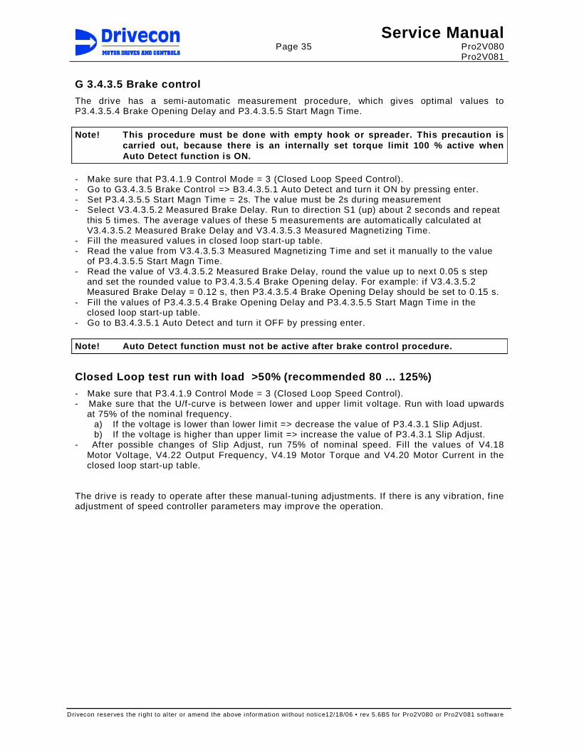
Page 35
Service Manual Pro2V080 Pro2V081
Drivecon reserves the right to al ter or amend the above information wi thout notice12/18/06 • rev 5.6B5 for Pro2V080 or Pro2V081 software
G 3.4.3.5 Brake control
The drive has a semi-automatic measurement procedure, which gives optimal values to P3.4.3.5.4 Brake Opening Delay and P3.4.3.5.5 Start Magn Time. Note! This procedure must be done with empty hook o r spreader. This precaution is
carried out, because there is an internally set tor que limit 100 % active when Auto Detect function is ON.
- Make sure that P3.4.1.9 Control Mode = 3 (Closed Loop Speed Control). - Go to G3.4.3.5 Brake Control => B3.4.3.5.1 Auto Detect and turn it ON by pressing enter. - Set P3.4.3.5.5 Start Magn Time = 2s. The value must be 2s during measurement - Select V3.4.3.5.2 Measured Brake Delay. Run to direction S1 (up) about 2 seconds and repeat
this 5 times. The average values of these 5 measurements are automatically calculated at V3.4.3.5.2 Measured Brake Delay and V3.4.3.5.3 Measured Magnetizing Time.
- Fill the measured values in closed loop start-up table. - Read the value from V3.4.3.5.3 Measured Magnetizing Time and set it manually to the value
of P3.4.3.5.5 Start Magn Time. - Read the value of V3.4.3.5.2 Measured Brake Delay, round the value up to next 0.05 s step
and set the rounded value to P3.4.3.5.4 Brake Opening delay. For example: if V3.4.3.5.2 Measured Brake Delay = 0.12 s, then P3.4.3.5.4 Brake Opening Delay should be set to 0.15 s.
- Fill the values of P3.4.3.5.4 Brake Opening Delay and P3.4.3.5.5 Start Magn Time in the closed loop start-up table.
- Go to B3.4.3.5.1 Auto Detect and turn it OFF by pressing enter. Note! Auto Detect function must not be active after brake control procedure.
Closed Loop test run with load >50% (recommended 8 0 ... 125%)
- Make sure that P3.4.1.9 Control Mode = 3 (Closed Loop Speed Control). - Make sure that the U/f-curve is between lower and upper l imit voltage. Run with load upwards
at 75% of the nominal frequency. a) If the voltage is lower than lower l imit => decrease the value of P3.4.3.1 Slip Adjust. b) If the voltage is higher than upper limit => increase the value of P3.4.3.1 Slip Adjust.
- After possible changes of Slip Adjust, run 75% of nominal speed. Fil l the values of V4.18 Motor Voltage, V4.22 Output Frequency, V4.19 Motor Torque and V4.20 Motor Current in the closed loop start-up table.
The drive is ready to operate after these manual-tuning adjustments. If there is any v ibration, fine adjustment of speed controller parameters may improve the operation.

Page 36
Service Manual Pro2V080 Pro2V081
Drivecon reserves the right to al ter or amend the above information wi thout notice12/18/06 • rev 5.6B5 for Pro2V080 or Pro2V081 software
CLOSED LOOP START-UP TABLE
drive serial number
drive type code
Project number
Project name
Motor type code: No Load Current: A
Power: kW
Nom Voltage: V
Nom Current: A
ED: %
Nom Frequency: Hz
Nom Speed: rpm
Motor nominal flux current (no load current) measur ement Note! P3.4.1.9 Control Mode = 0 (Open Loop Freq Control) Load below 5%. P3.4.2.1.1=0%, P3.4.2.1.2=0%, P3.4.2.1.3=0Hz, P3.4.2.1.4 = 0 (OFF). V4.18 Motor Voltage V
V4.22 Output Frequency Hz
V4.20 Motor Current A
Closed Loop test run without load Note! P3.4.1.9 Control Mode = 3 (Closed Loop Speed Control) Record tuned value of
P3.4.1.5 Motor Nom Flux A
V4.19 Motor Torque %
V4.18 Motor Voltage V
V4.22 Output Frequency Hz
V4.20 Motor Current A
Brake control Record values of V3.4.3.5.2
Measured Brake Delay s V3.4.3.5.3 Measured Magn Time s
P3.4.3.5.4 Brake Opening delay s
P3.4.3.5.5 Start Magn Time s
Closed Loop test run with load >50% (recommended 8 0 ... 125 %) Note! P3.4.1.9 Control Mode = 3 (Closed Loop Speed Control) Record tuned value of
P3.4.3.1 Slip Adjust %
V4.19 Motor Torque %
V4.18 Motor Voltage V
V4.22 Output Frequency Hz
V4.20 Motor Current A
Speed Controller Record values of P3.4.3.3
Speed Ctrl Kp P3.4.3.4 Speed Ctrl Ti ms

Page 37
Service Manual Pro2V080 Pro2V081
Drivecon reserves the right to al ter or amend the above information wi thout notice12/18/06 • rev 5.6B5 for Pro2V080 or Pro2V081 software
4.6 Brake Slip Feature
This inverter is equipped with a programmable brake slip detection safety feature that can be
activated during closed loop operation. This feature, when activated, is designed to allow the hoist motor to continue to support a suspended load during hoist brake slip or failure. Electric power to the inverter must remain uninterrupted during such failure for this feature to remain effective.
Power interruption to the inverter during hoist brake slip or failure, regardless of cause, including power interruption caused by operator engagement of the “E” or “Emergency” stop button, could result in the dropping of the load which creates a hazardous situation, which if not avoided, could result in property damage and/or death or serious injury to personnel located in, on, or around the subject crane.
Alarm code “A81” is temporarily displayed on the inverter keypad when the brake slip detection
feature detects a hoist brake slip or failure. In this event, the crane must be moved to a safe location and the load lowered to the ground prior to cutting crane/hoist power. Corrective action should be taken to repair the hoist brake prior to resuming normal operation.
The brake slip detection feature MUST, when activated, be used in conjunction with an audible
and/or visual alarm and product labeling sufficient to warn the crane operator of the existence of an “A81” inverter condition (detection of hoist brake slip or failure) and the above-referenced power maintenance requirement.
The default setting for the programmable brake slip detection safety feature at the time of factory delivery is off or deactivated unless factory activation is requested by the customer in writing at the time of order. Feature activation requires the installation and/or connection of crane/hoist circuits and/or components external to the inverter (see Service Manual) and should be completed only by trained and qualified personnel experienced with inverters equipped with this feature.
Specific crane operator training designed to identify both those hazards identified herein and
those procedures required to minimize those hazards MUST be conducted by the crane owner immediately following feature activation and prior to crane use.
4.6.1 Description of brake slip feature
When the motor holding brake slips or fails leading to the rotation of the motor/encoder, the Speed Supervision Unit (SSU board) inside the drive senses at least -5Hz of motor frequency generated by the encoder pulses. When this happens, the drive is energized and magnetizes the motor holding the load keeping it at zero speed and sends a command releasing the brake and activating the externally connected warning horn or alarm (if installed). This should allow enough time for the operator to safely lower the load. Drive tuning, external to the drive electrical connections and encoder installation/quality/coupling to the motor are key factors for this feature to work precisely. Consult above warning label. The e-stop SHOULD NOT BE activated and the power to the crane/hoist SHOULD NOT BE turned off since the drive requires this power supply to be energized and to magnetize the motor which is holding the load. Consult above warning label.

Page 38
Service Manual Pro2V080 Pro2V081
Drivecon reserves the right to al ter or amend the above information wi thout notice12/18/06 • rev 5.6B5 for Pro2V080 or Pro2V081 software
4.6.2 Activation of Brake Slip Feature
Feature activation requires the installation and/or connection of crane/hoist circuits and/or components external to the inverter and should be completed only by trained and qualified personnel experienced with inverters equipped with this feature.
Activating this feature depends mainly on the setting of parameters P3.6.8, P3.2.5.2 and P3.4.1.21.9 as well as the specific wiring design of the hoisting controls. Furthermore, all other drive parameters should be properly closed loop tuned for proper drive functionality. The need for how to set P3.6.8 parameter wil l be dictated by the requirements of each application. This parameter can be set to either “Not Used,” “S1 Allowed,” “S1 Slow Spd,” or “S1 Disabled.” (Consult parameter description section 5 in this manual). When P3.6.8 is set to “0 =Not Used”, the brake slip detection feature is disabled which prevents the drive from going into brake slip mode and hold the load. When P3.6.8 is set to “1=S1 Allowed”, hoisting in any speed in the up direction is allowed. Lowering in any speed is allowed. (Consult the factory prior to setting this parameter as Brake Slip can be by passed) When P3.6.8 is set to “2=S1 Slow Spd”, hoisting in slow speed is only allowed in the up direction. Lowering in any speed is allowed. (Consult the factory prior to setting this parameter as Brake Slip can be by passed) When P3.6.8 is set to “3=S1 Disabled”, hoisting in the up direction in not allowed but only lowering in any speed is allowed. (Typical factory setting) As stated above, it is strongly recommended to use some audible and/or visual alert to notify the operator if the drive detects brake slip. Regardless of which type of device will be used, a relay output must be programmed for Brake Slip. As a default, the drive wil l be programmed to use ROD1 for this function. This is achieved by programming P3.2.5.2 set to 21=brake slip. Set P3.4.1.21.9 Stop Function to 1/Ramping All drive parameters, including the brake slip parameters (if feature required) should be verified and set on site during start-up of the drive.
4.6.3 Brake Slip Feature Field Testing Procedure Power interruption to the inverter during hoist brake slip or failure, regardless of cause,
including power interruption caused by operator engagement of the “E” or “Emergency” stop button, could result in the dropping of the load which creates a hazardous situation, which if not avoided, could result in property damage and/or death or serious injury to personnel located in, on, or around the subject crane.
Do not cut power or activate the e-stop when field testing this feature. The load should be lowered to the ground.
Please read this prior to testing:
- Familiarize yourself with this section 4.6 from t he beginning prior to field testing this feature as some pre-requirements are vital for this feature to work as designed. - All precautionary safety measures should be taken as in any crane load testing. - You will require to lift a load (30% to 50% of no minal load maximum) to turn the drum when the brake is manually released. (DO NOT U SE FULL LOAD) - Only trained and qualified personnel experienced with inverters equipped with this feature should attempt this testing .

Page 39
Service Manual Pro2V080 Pro2V081
Drivecon reserves the right to al ter or amend the above information wi thout notice12/18/06 • rev 5.6B5 for Pro2V080 or Pro2V081 software
- A dedicated alarm device (horn or light) must be wired and connected correctly to the circuitry/drive output per schematics prior to testing. If an alarm device is not available or connected, activation or testing of th is function must not be performed. - Motor encoder, encoder coupling, installation and functionality should be in proper working conditions. - Do not turn power off to the crane/hoist during t his test as it is needed for the drive. - Make sure “brake slip” warning pendant tag, enclosu re warning label near
disconnect, crane runway warning label and drive wa rning sticker are applied and existent.
Step 1: Verify drive is tuned and running properly prior to brake slip feature activation. (see serv ice manual section 4.5 for closed loop hoist tuning instructions) Step 2: Verify alarm is connected per schematics Step 3: Verify section 4.6.2 above is completed and all parameters programmed as needed. Step 4: Identify/mark the hoist holding brake contactor(s) (see schematics) (this step is needed for manual release in next steps) The below steps will require two individuals. One to monitor drum rotation and one to deactivate the holding brake. Step5: Lift the load (use 30% to 50% maximum of nominal load) approximately 1 to 2 ft. off the ground. Step6: Manually depress and hold the brake contactor(s) for 1-2 seconds maximum to disengage the holding brake(s) to allow the load to begin to drop, keeping watch of the hoist drum rotation not to exceed 90° of angular rotation. The drive sh ould detect brake slip (within 1-2 seconds of releasing the brake) at about –5Hz frequency sent by the encoder pulses and subsequently activating the drive to hold the load. If the drive does not hold the load within 1-2 seconds after releasing the brake or exceeds 90° of hoist drum angular rotation, release the brake contactor to engage the brake and stop the load. This implies the test has failed. Re-examine all drive programming, external circuitry and connections. Re-start testing procedure. Consult factory for support. Do not hold brake contactor depressed more than 1-2 seconds as this will cause the load to accelerate and damage could occur to the load, ground and even the crane/hoist/braking system. Once the drive is active and holds the load, verify that the alarm system (horn/light) is active and Alarm code “A81” is temporarily displayed on the inverter keypad suggesting brake slip. DO NOT ENGAGE E-STOP OR CUT POWER TO THE INVERTER AS THIS WILL DROP THE LOAD. Step 7: Lower the load to the ground using the pendant station/other control as soon as possible. Do not leave drive/load in this brake slip mode more than is required to safely bring the load down as this could damage the drive and motor. Step 8: Finally, when load is securely on the ground, then and only then, turn off all crane power supply to reset the brake slip function and drive. Wait for 5 minutes then power up crane and check that hoist function is normal. Contact Drivecon technical support for assistance if required at 1-800-374-8266.
4.6.4 What to do in case of brake slip - Familiarize yourself with this section 4.6 from t he beginning prior to operating the crane . Only qualified and trained operators should operate the crane.

Page 40
Service Manual Pro2V080 Pro2V081
Drivecon reserves the right to al ter or amend the above information wi thout notice12/18/06 • rev 5.6B5 for Pro2V080 or Pro2V081 software
Once brake slip has been detected by the drive, an audible and/or visual alarm system will be activated. Once this alarm is active, the hoist will go into load hold mode at zero speed where the load will remain suspended by the energized motor. Locate a safe space and lower the load as soon as possible to the ground. Raising the load might not be possible and depends on the programming of Parameter P3.6.8 (consult section 4.6.2 of the serv ice manual). Do not engage the e-stop on the pendant station or radio control unit as this will drop the load.
Power interruption to the inverter during hoist brake slip or failure, regardless of cause, including power interruption caused by operator engagement of the “E” or “Emergency” stop button, could result in the dropping of the load which creates a hazardous situation, which if not avoided, could result in property damage and/or death or serious injury to personnel located in, on, or around the subject crane.
Alarm code “A81” is temporarily displayed on the inverter keypad when the brake slip detection feature detects a hoist brake slip or failure. In this event, the crane must be moved to a safe location and the load lowered to the ground prior to cutting crane/hoist power. Corrective action should be taken to repair the hoist brake prior to resuming normal operation.
In case of brake slip condition, lower the load to the ground safely and contact your crane service organization as soon as possible for immedi ate service.
4.6.5 Service on hoist motor/encoder/brake with Bra ke Slip feature active
In the event the power is not turned off to the hoist inverter and the hoist motor/encoder/brake is being serv iced, any rotation of the motor/encoder/brake could activate the drive and starts to feed current to the motor. Power should be turned off/crane tagged and locked prior to any serv ice being performed on the crane.

Page 41
Service Manual Pro2V080 Pro2V081
Drivecon reserves the right to al ter or amend the above information wi thout notice12/18/06 • rev 5.6B5 for Pro2V080 or Pro2V081 software
5 PARAMETER DESCRIPTIONS The parameters are assorted to groups. Below is the group map of the parameters based on the software version Pro2V080 and Pro2V081. The groups are shown in control keypad according to the password level and the selected functions. All Groups are not always v iewable in the control keypad. A sign of + in the f ront of the group code means that the group is v isible in keypad, but only if the group function is selected.
G3 ParametersG3.1 Basic ParametersG3.2 I/O Parameters
G3.2.1 Digital InputsG3.2.2 Analog Input 1G3.2.3 Analog Input 2
+ G3.2.3.7 AU-Speed Ref+ G3.2.3.8 Torque Reference+ G3.2.3.9 Speed Correction+ G3.2.3.10 Torque Limit+ G3.2.3.11 Load Feedback
G3.2.4 Analog OutputG3.2.4.1 Aout1 FunctionG3.2.4.2 Aout2 Function
G3.2.5 Relay Outputs G3.3 Drive Control
G3.3.6 Limit Functions+ G3.3.7 Ramp2
G3.3.8 Advanced Ramps+ G3.3.9 Multistep+ G3.3.10 SSU
G3.3.11 Prohib Freq+ G3.3.12 Multicare
G3.3.12.1 Multicare 1G3.3.12.2 Multicare 2
G3.3.13 Torque ControlG3.3.14 Load ControlG3.3.15 Sway ControlG3.3.16 Joystick Filter
G3.4 Motor ParametersG3.4.1 Motorset 1
G3.4.1.21 AdditionalG3.4.1.22 ESRG3.4.1.23 Current Control
+ G3.4.2 Open Loop 1G3.4.2.1 U/f CurveG3.4.2.2 Brake ControlP3.4.2.3 OL Autotuning 1
+ G3.4.3 Closed Loop 1G3.4.3.5 Brake ControlG3.4.3.6 CL Autotuning 1
+ G3.4.4 Motorset 2G3.4.4.21 AdditionalG3.4.4.22 ESRG3.4.4.23 Current Control
+ G3.4.5 Open Loop 2G3.4.5.1 U/f CurveG3.4.5.2 Brake ControlP3.4.5.3 OL Autotuning 2
+ G3.4.6 Closed Loop 2G3.4.6.5 Brake ControlG3.4.6.6 CL Autotuning 2
G3.4.7 ExpertG3.4.7.2 Current Ctrl OLG3.4.7.3 Speed Ctrl CL
+ G3.5 Bus ParametersG3.5.2 DiagnosticG3.5.3 Bus Control
G3.6 ProtectionG3.7 Laboratory
+ G3.8 System BusG3.8.3 SynchronizationG3.8.4 Tandem
+ G3.9 PLC Parameters

Page 42
Service Manual Pro2V080 Pro2V081
Drivecon reserves the right to al ter or amend the above information wi thout notice12/18/06 • rev 5.6B5 for Pro2V080 or Pro2V081 software
G4 MonitoringV4.22 Output Frequency Note! Returns automatically here.G4.1 Parameter Backup
G4.1.4 Factory DefaultG4.2 Analog I/OG4.3 Relay OutputG4.4 Operate CountersG4.5 Fault Counter
+ G4.6 Bus ControlG4.7 Digital Input
G4.7.1 DI StatusG4.7.2 DI Functions
+ G4.8 SSUG4.9 Service
G4.9.10 Max Current+ G4.10 Sway Control
G4.23 Multimonitor
G5 Panel Control
M6 System MenuS6.3 Copy ParametersS6.4 ParamComparisonS6.5 SecurityS6.6 Keypad SettingsS6.7 HW SettingsS6.8 System Info
S6.8.1 Total CountersS6.8.2 Trip CountersS6.8.3 SoftwareS6.8.4 ApplicationsS6.8.5 HardwareS6.8.6 Expander boardsS6.8.7 Debug
S6.9 Power MonitorS6.11 Power Multimon.
M7 Active Faults
M8 Fault History

Page 43
Service Manual Pro2V080 Pro2V081
Drivecon reserves the right to al ter or amend the above information wi thout notice12/18/06 • rev 5.6B5 for Pro2V080 or Pro2V081 software
Below are listed the default values for parameters in hoisting and traveling. Also are listed the password lock levels for parameter P3.1.1. Some of the parameters have a value marked with X. The values of these parameters differ depending on motor/voltage. This parameter l ist is based on the software version Pro2V080 and Pro2V081. G3 Parameters
G3.1 Basic Parameters OL Travel CL Travel CL Hoist OL Hoist Unit PW 1 Descripti on P3.1.1 Password 768 768 768 768 1
V3.1.2 Supply Voltage X X X X V 1 5 = F 380V - 500VV3.1.3 Device 1 1 1 1 1 1 = Process
G3.2 I/O Parameters OL Travel CL Travel CL Hoist OL Hoist Unit PW 2 Descripti onG3.2.1 Digital Inputs OL Travel CL Travel CL Hoist OL Ho ist Unit PW 3 Description
P3.2.1.1 Motor Set 2 0 0 0 0 3 0 = Not Used1 = DIA32 = DIA43 = DIA54 = DID15 = DID26 = DID37 = DID48 = DID59 = Always ON10 = Always OFF
P3.2.1.2 SSL 0 0 0 0 3 Same as 3.2.1.1P3.2.1.3 ESR 0 0 0 0 3 Same as 3.2.1.1P3.2.1.4 Micro Speed Sel 0 0 0 0 3 Same as 3.2.1.1P3.2.1.5 Alt Control Sel 0 0 0 0 3 Same as 3.2.1.1P3.2.1.6 Profibus Control 0 0 0 0 3 0 = Not Used
1 = DIA5P3.2.1.7 Ramp2 0 0 0 0 3 Same as 3.2.1.1P3.2.1.8 Trq Limit 0 0 0 0 3 Same as 3.2.1.1P3.2.1.9 AP 1 1 1 1 3 0 = Not Used
1 = DIA32 = Always ON3 = Always OFF
P3.2.1.10 CMS 1 1 1 1 3 0 = Not Used1 = DIA42 = Always ON3 = Always OFF
P3.2.1.11 EP-Hold 0 0 0 0 3 0 = Not Used1 = DIA32 = DIA43 = DIA54 = DID15 = DID26 = DID37 = DID48 = DID5
P3.2.1.12 Multistep2 0 0 0 0 3 0 = Not Used1 = DIA32 = DIA4
P3.2.1.13 Multistep3 0 0 0 0 3 0 = Not Used1 = DIA42 = DIA5
P3.2.1.14 Multistep4 0 0 0 0 3 0 = Not Used1 = DIA52 = DID1
P3.2.1.15 Multistep5 0 0 0 0 3 0 = Not Used1 = DID12 = DID2
P3.2.1.16 PO/MS 0 0 0 0 3 Same as 3.2.1.11P3.2.1.17 S11 1 1 1 1 3 0 = Not Used
1 = DID22 = DIA53 = Always ON4 = Always OFF
P3.2.1.18 S21 1 1 1 1 3 0 = Not Used1 = DID32 = DID13 = Always ON4 = Always OFF
P3.2.1.19 S11 & S21 0 0 0 0 3 Same as 3.2.1.11P3.2.1.20 S12 1 1 1 1 3 0 = Not Used
1 = DID42 = DID2 & DID4
P3.2.1.21 S22 1 1 1 1 3 0 = Not Used1 = DID52 = DID3 & DID5
P3.2.1.22 MF1 Input 0 0 0 0 3 Same as 3.2.1.11P3.2.1.23 MF1 Operation 0 0 0 0 3 0=Not Used
1=Brake Pedal2=Inching3=Fault Reset4=S-CurveInhib5=Tare6=Brake Feedb7=SlackBypass8=Synchro9=Brake Pedal210=Overweight
P3.2.1.24 MF2 Input 0 0 0 0 3 Same as 3.2.1.11P3.2.1.25 MF2 Operation 0 0 0 0 3 Same as 3.2.1.23
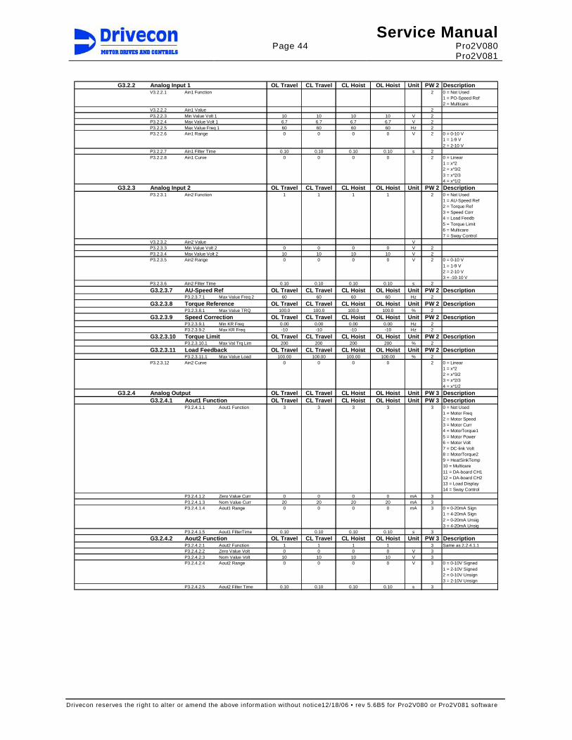
Page 44
Service Manual Pro2V080 Pro2V081
Drivecon reserves the right to al ter or amend the above information wi thout notice12/18/06 • rev 5.6B5 for Pro2V080 or Pro2V081 software
G3.2.2 Analog Input 1 OL Travel CL Travel CL Hoist OL Ho ist Unit PW 2 Description
V3.2.2.1 Ain1 Function 2 0 = Not Used1 = PO-Speed Ref2 = Multicare
V3.2.2.2 Ain1 Value 2P3.2.2.3 Min Value Volt 1 10 10 10 10 V 2P3.2.2.4 Max Value Volt 1 6.7 6.7 6.7 6.7 V 2P3.2.2.5 Max Value Freq 1 60 60 60 60 Hz 2P3.2.2.6 Ain1 Range 0 0 0 0 V 2 0 = 0-10 V
1 = 1-9 V2 = 2-10 V
P3.2.2.7 Ain1 Filter Time 0.10 0.10 0.10 0.10 s 2P3.2.2.8 Ain1 Curve 0 0 0 0 2 0 = Linear
1 = x^22 = x^3/23 = x^2/34 = x^1/2
G3.2.3 Analog Input 2 OL Travel CL Travel CL Hoist OL Ho ist Unit PW 2 DescriptionP3.2.3.1 Ain2 Function 1 1 1 1 2 0 = Not Used
1 = AU-Speed Ref2 = Torque Ref3 = Speed Corr4 = Load Feedb5 = Torque Limit6 = Multicare7 = Sway Control
V3.2.3.2 Ain2 Value VP3.2.3.3 Min Value Volt 2 0 0 0 0 V 2P3.2.3.4 Max Value Volt 2 10 10 10 10 V 2P3.2.3.5 Ain2 Range 0 0 0 0 V 2 0 = 0-10 V
1 = 1-9 V2 = 2-10 V3 = -10-10 V
P3.2.3.6 Ain2 Filter Time 0.10 0.10 0.10 0.10 s 2
G3.2.3.7 AU-Speed Ref OL Travel CL Travel CL Hoist OL Ho ist Unit PW 2 DescriptionP3.2.3.7.1 Max Value Freq 2 60 60 60 60 Hz 2
G3.2.3.8 Torque Reference OL Travel CL Travel CL Hoist O L Hoist Unit PW 2 DescriptionP3.2.3.8.1 Max Value TRQ 100.0 100.0 100.0 100.0 % 2
G3.2.3.9 Speed Correction OL Travel CL Travel CL Hoist OL Hoist Unit PW 2 DescriptionP3.2.3.9.1 Min KR Freq 0.00 0.00 0.00 0.00 Hz 2P3.2.3.9.2 Max KR Freq -10 -10 -10 -10 Hz 2
G3.2.3.10 Torque Limit OL Travel CL Travel CL Hoist OL H oist Unit PW 2 DescriptionP3.2.3.10.1 Max Val Trq Lim 200 200 200 200 % 2
G3.2.3.11 Load Feedback OL Travel CL Travel CL Hoist OL Hoist Unit PW 2 DescriptionP3.2.3.11.1 Max Value Load 100.00 100.00 100.00 100.00 % 2
P3.2.3.12 Ain2 Curve 0 0 0 0 2 0 = Linear1 = x^22 = x^3/23 = x^2/34 = x^1/2
G3.2.4 Analog Output OL Travel CL Travel CL Hoist OL Hoi st Unit PW 3 DescriptionG3.2.4.1 Aout1 Function OL Travel CL Travel CL Hoist OL Hoist Unit PW 3 Description
P3.2.4.1.1 Aout1 Function 3 3 3 3 3 0 = Not Used1 = Motor Freq2 = Motor Speed3 = Motor Curr4 = MotorTorque15 = Motor Power6 = Motor Volt7 = DC-link Volt8 = MotorTorque29 = HeatSinkTemp10 = Multicare11 = DA-board CH112 = DA-board CH213 = Load Display14 = Sway Control
P3.2.4.1.2 Zero Value Curr 0 0 0 0 mA 3P3.2.4.1.3 Nom Value Curr 20 20 20 20 mA 3P3.2.4.1.4 Aout1 Range 0 0 0 0 mA 3 0 = 0-20mA Sign
1 = 4-20mA Sign2 = 0-20mA Unsig3 = 4-20mA Unsig
P3.2.4.1.5 Aout1 FilterTime 0.10 0.10 0.10 0.10 s 3
G3.2.4.2 Aout2 Function OL Travel CL Travel CL Hoist OL Hoist Unit PW 3 DescriptionP3.2.4.2.1 Aout2 Function 1 1 1 1 3 Same as 2.2.4.1.1P3.2.4.2.2 Zero Value Volt 0 0 0 0 V 3P3.2.4.2.3 Nom Value Volt 10 10 10 10 V 3P3.2.4.2.4 Aout2 Range 0 0 0 0 V 3 0 = 0-10V Signed
1 = 2-10V Signed2 = 0-10V Unsign3 = 2-10V Unsign
P3.2.4.2.5 Aout2 Filter Time 0.10 0.10 0.10 0.10 s 3

Page 45
Service Manual Pro2V080 Pro2V081
Drivecon reserves the right to al ter or amend the above information wi thout notice12/18/06 • rev 5.6B5 for Pro2V080 or Pro2V081 software
G3.2.5 Relay Outputs OL Travel CL Travel CL Hoist OL Hoi st Unit PW 3 Description
P3.2.5.1 ROB1 4 4 4 4 3 0 = Not Used1 = Fault2 = BrakeControl3 = Run4 = Ready5 = Ready Invert6 = Fan7 = E-stop8 = Rev Plugging9 = At Speed10 = S2 Active11 = Safety Brake12 = ESR Active13 = ESR Allowed14 = Temperature115 = Temperature216 = Alarm17 = Set 2 Active18 = MS Alarm19 = Exceed SSL120 = Exceed SSL221 = Brake Slip22 = Overweight23 = Slack Cable24 = DelayedK7Inv25 = Motor Set226 = SwayCntlOn27 = SwayCntlRun28 = SimitSwTest29 = Bus Output
P3.2.5.2 ROD1 6 6 6 6 3 Same as 3.2.5.1P3.2.5.3 Fan Off Delay 300 300 300 300 s 3P3.2.5.4 Temp Limit 20 20 20 20 °C 3P3.2.5.5 ROE1 0 0 0 0 3 Same as 3.2.5.1P3.2.5.6 ROE2 0 0 0 0 3 Same as 3.2.5.1P3.2.5.7 ROE3 0 0 0 0 3 Same as 3.2.5.1P3.2.5.8 DOA1 0 0 0 0 3 Same as 3.2.5.1
G3.3 Drive Control OL Travel CL Travel CL Hoist OL Hoist Unit PW 3 Descripti onP3.3.1 Acc Start Shape 0.200 0.200 0.000 0.000 s 3P3.3.2 Acc End Shape 0.200 0.200 0.200 0.200 s 3P3.3.3 Dec Start Shape 0.200 0.200 0.200 0.200 s 3P3.3.4 Dec End Shape 0.200 0.200 0.000 0.000 s 3P3.3.5 Ch Ref at Run 0 0 0 0 3 0 = No
1 = Yes
G3.3.6 Limit Functions OL Travel CL Travel CL Hoist OL H oist Unit PW 3 DescriptionP3.3.6.1 Slow Speed Freq 6 6 15 15 Hz 3V3.3.6.2 Distance Counter m 3P3.3.6.3 Slow Distance 0.00 0.00 0.00 0.00 m 3P3.3.6.4 Nominal Speed 0.00 0.00 0.00 0.00 m/min 3P3.3.6.5 Second SpdLimS1 20 20 20 20 Hz 3P3.3.6.6 Second SpdLimS2 20 20 20 20 Hz 3P3.3.6.7 End Reset Delay 1.00 1.00 1.00 1.00 s 3P3.3.6.8 End Limit Action 1 1 1 1 3 0 = Normal Stop
1 = Brake Stop 12 =Trq Lim Stop3 = StopDistance4 = Brake Stop 2
P3.3.6.9 Inching Time 1 1 1 1 s 3B3.3.6.10 Nom Speed Calib 3 0=Off
1=OnP3.3.6.11 Calib Distance 2.000 2.000 2.000 2.000 m 3
G3.3.7 Ramp2 OL Travel CL Travel CL Hoist OL Hoist Unit PW 3 DescriptionP3.3.7.1 Acc Time 2 5.0 5.0 2 2 s 3P3.3.7.2 Dec Time 2 5.0 5.0 2 2 s 3
G3.3.8 Advanced Ramps OL Travel CL Travel CL Hoist OL Ho ist Unit PW 3 DescriptionP3.3.8.1 Acc Ramp Form 0 0 0 0 3 0 = Linear
1 = Form 12 = Form 2 3 = Form 34 = Form 4
V3.3.8.2 Acc TotalRamp Time s 3P3.3.8.3 Dec Ramp Form 0 0 0 0 3 0 = Linear
1 = Form 12 = Form 2 3 = Form 34 = Form 4
V3.3.8.4 Dec TotalRamp Time s 3P3.3.8.5 Stop Ramp S1 0.0 0.0 0.0 0.0 s 3P3.3.8.6 Stop Ramp S2 0.0 0.0 0.0 0.0 s 3P3.3.8.7 Direction Change 0.0 0.0 0.0 0.0 s 3
G3.3.9 Multistep OL Travel CL Travel CL Hoist OL Hoist Unit PW 3 Descripti onP3.3.9.1 Multistep Logic 0 0 0 0 3 0 = MSL
1 = MSH2 = MSL Alarm
P3.3.9.2 Multistep 2 Freq 15.00 15.00 15.00 15.00 Hz 3P3.3.9.3 Multistep 3 Freq 30.00 30.00 30.00 30.00 Hz 3P3.3.9.4 Multistep 4 Freq 45.00 45.00 45.00 45.00 Hz 3P3.3.9.5 Multistep 5 Freq 60.00 60.00 60.00 60.00 Hz 3

Page 46
Service Manual Pro2V080 Pro2V081
Drivecon reserves the right to al ter or amend the above information wi thout notice12/18/06 • rev 5.6B5 for Pro2V080 or Pro2V081 software
G3.3.10 SSU OL Travel CL Travel CL Hoist OL Hoist Unit PW 3 Descripti on
P3.3.10.1 Speed Dif Limit 30.0 30.0 30.0 30.0 % 3P3.3.10.2 Stall Sup Time 1.0 1.0 1.0 1.0 s 3P3.3.10.3 Overspd Lim Sel 0 0 0 0 3 0 = Set 1 ESR
1 = Set 2 ESR2 = Set1 & Set2
G3.3.11 Prohib Freq OL Travel CL Travel CL Hoist OL Hois t Unit PW 3 DescriptionP3.3.11.1 Prohib Freq Low 0.00 0.00 0.00 0.00 Hz 3P3.3.11.2 Prohib Freq High 0.00 0.00 0.00 0.00 Hz 3
G3.3.12 Multicare OL Travel CL Travel CL Hoist OL Hoist Unit PW 3 Descripti onG3.3.12.1 Multicare 1 OL Travel CL Travel CL Hoist OL Ho ist Unit PW 3 Description
B3.3.12.1.1 Test Voltage Min 3 OffOn
B3.3.12.1.2 Test Voltage Max 3 OffOn
V3.3.12.1.3 Ain1 Value V 3P3.3.12.1.4 Min Value Volt 1 10.000 10.000 10.000 10.000 V 3P3.3.12.1.5 Max Value Volt 1 6.700 6.700 6.700 6.700 V 3
G3.3.12.2 Multicare 2 OL Travel CL Travel CL Hoist OL Ho ist Unit PW 3 DescriptionB3.3.12.2.1 Test Voltage Min 3 Off
OnB3.3.12.2.2 Test Voltage Max 3 Off
OnV3.3.12.2.3 Ain2 Value V 3P3.3.12.2.4 Min Value Volt 2 0.000 0.000 0.000 0.000 V 3P3.3.12.2.5 Max Value Volt 2 10.000 10.000 10.000 10.000 V 3
G3.3.13 Torque Control OL Travel CL Travel CL Hoist OL H oist Unit PW 4 DescriptionP3.3.13.1 Free Rolling Trq 5.0 5.0 5.0 5.0 % 4P3.3.13.2 Trq Inc Ramp 0.30 0.30 0.30 0.30 s 4P3.3.13.3 Trq Dec Ramp 0.10 0.10 0.10 0.10 s 4P3.3.13.4 Brake Pedal Torq 150 150 150 150 % 4
G3.3.14 Load Control OL Travel CL Travel CL Hoist OL Hoi st Unit PW 3 DescriptionP3.3.14.1 Accel Torque 100 100 100 100 % 3P3.3.14.2 Slack Cable Mode 0 0 0 0 3 0=Not Used
1=Alarm2=S2 Disabled3=S2 Slow Spd4=Trq+S2Slow5=Trq+S2Disab
P3.3.14.3 Slack Cbl Level 1 1 1 1 % 3P3.3.14.4 Slack Cable Filt 1 1 1 1 s 3P3.3.14.5 Load Disp Mode 0 0 0 0 3 0=Not Used
1=Update Mode12=Update Mode2
P3.3.14.6 Load Disp 0V Trq 1 1 1 1 % 3P3.3.14.7 Load Disp10V Trq 100 100 100 100 % 3V3.3.14.8 Filtered Torque 3P3.3.14.9 Overweight Mode 0 0 0 0 3 0=Not Used
1=Alarm2=S1 Disabled
P3.3.14.10 Overweight Level 100 100 100 100 % 3P3.3.14.11 Overweight Filt 1 1 1 1 s 3V3.3.14.12 Meas Acc Trq % 3B3.3.14.13 Detect Acc Trq 3 0=Off
1=On
G3.3.15 Sway Control OL Travel CL Travel CL Hoist OL Hoi st Unit PW 3 DescriptionP3.3.15.1 Acc Time Coeff 100 100 100 100 % 3P3.3.15.2 Dec Time Coeff 100 100 100 100 % 3P3.3.15.3 Ramp Mode 0 0 0 0 3 0 = Off
1 = Smooth2 = Fast3 = Smooth1Fast24 = Fast1Smooth2
P3.3.15.4 HeightCorrection 0.00 0.00 0.00 0.00 m 3V3.3.15.5 Swing Time s 3P3.3.15.6 Slow Down Mode 0 0 0 0 3 0 = Off
1 = OnP3.3.15.7 Jog Time Window 0.0 0.0 0.0 0.0 s 3P3.3.15.8 Sway Control Mode 0 0 0 0 3 0 = Not Used
1 = Lite2 = Standard3 = Pro4 = Demo 100h
P3.3.15.9 Dir Change Limit 100 100 100 100 % 3P3.3.15.10 Max Height 40.00 40.00 40.00 40.00 m 3P3.3.15.11 Load Ratio 0 0 0 0 % 3P3.3.15.12 License Key 1 0 0 0 0 3P3.3.15.13 License Key 2 0 0 0 0 3
G3.3.16 Joystick Filter OL Travel CL Travel CL Hoist OL Hoist Unit PW 3 DescriptionP3.3.16.1 Joystick Filter 0 0 0 0 3 0=Off
1=OnP3.3.16.2 Max Filter Range 20 20 20 20 % 3P3.3.16.3 Max Filter 1.5 1.5 1.5 1.5 s 3P3.3.16.4 Min Filter 0.00 0.00 0.00 0.00 s 3

Page 47
Service Manual Pro2V080 Pro2V081
Drivecon reserves the right to al ter or amend the above information wi thout notice12/18/06 • rev 5.6B5 for Pro2V080 or Pro2V081 software
G3.4 Motor Parameters OL Travel CL Travel CL Hoist OL Hoist Unit PW 2 Descripti on
G3.4.1 Motorset 1 OL Travel CL Travel CL Hoist OL Hoist Unit PW 2 Descripti onP3.4.1.1 Motor Nom Volt X X X X V 2P3.4.1.2 Motor Nom Freq X X X X Hz 2P3.4.1.3 Motor Nom Speed X X X X rpm 2P3.4.1.4 Motor Nom Curr X X X X A 2P3.4.1.5 Nom Flux Curr X X X X A 2P3.4.1.6 Motor Cos Phi X X X X 2
P3.4.1.7 Start Current 0.8 x P3.4.1.4Max 0.8 x In
P3.4.1.4Max 1.0 x In
1.2 x P3.4.1.4Max 1.0 x In
1.2 x P3.4.1.4Max 1.0 x In
A 2
P3.4.1.8 Current Limit 1.5 x P3.4.1.4Max 1.5 x In
1.5 x P3.4.1.4Max 1.5 x In
1.5 x P3.4.1.4Max 1.5 x In
1.5 x P3.4.1.4Max 1.5 x In
A 2
P3.4.1.9 Control Mode 0 3 3 1 2 0 = OL Freq Ctrl1 = OL Curr Ctrl2 = OL Spd Ctrl3 = Spd Ctrl CL4 = Trq Ctrl CL
P3.4.1.10 Accel Time 1 5 5 1.5 1.5 s 2P3.4.1.11 Decel Time 1 5 5 1.5 1.5 s 2P3.4.1.12 Advanced Ramps 0 0 0 0 2 0 = Normal
1 = Advanced12 = Adv Rev Plug3 = Ramp1&Ramp24 = PluggingCtrl
P3.4.1.13 Min Freq S1 X 1 1 X Hz 2P3.4.1.14 Min Freq S2 X 1 1 X Hz 2P3.4.1.15 Max Freq S1 X X X X Hz 2P3.4.1.16 Max Freq S2 X X X X Hz 2P3.4.1.17 ESR Point Freq 100 100 100 100 % 2P3.4.1.18 ESR Point Volt 100 100 100 100 % 2P3.4.1.19 Drive Selection 1 1 2 2 2 0 = None
1 = Travel2 = Hoist4 = Load Brake
P3.4.1.20 Pulse Number 0 8 8 0 2 0 = 241 = 362 = 483 = 724 = 325 = 646 = 807 = 1028 = 6009 = 100010 = 102411 = 200012 = 204813 = 51214 = 1200
G3.4.1.21 Additional OL Travel CL Travel CL Hoist OL Hoi st Unit PW 3 DescriptionP3.4.1.21.1 Trq Lim Function 0 0 0 0 3 0 = Not Used
1 = Constant2 = Adjustable
P3.4.1.21.2 Torque Limit Mot 200 200 200 200 % 3P3.4.1.21.3 Torque Limit Gen 200 200 200 200 % 3P3.4.1.21.4 Max Brake Del 0.0 0.0 0.0 0.0 s 3P3.4.1.21.5 Alt Control Mode 0 0 0 0 3 0 = OL Freq Ctrl
1 = OL Curr Ctrl2 = OL Spd Ctrl3 = Spd Ctrl CL4 = Trq Ctrl CL
P3.4.1.21.6 Correction Mode 0 0 0 0 3 0 = Not Used1 = Speed Corr2 = Multicare 13 = Multicare 24 = Synchro5 = Sway Control6 = SwayCtrlCorr
P3.4.1.21.7 Micro Speed Freq 10 10 10 10 Hz 3P3.4.1.21.8 Micro Speed Ramp 0 0 0 0 3 0 = Not Scaled
1 = ScaledP3.4.1.21.9 Stop Function 1 1 1 1 3 0 = Brake
1 = Ramping2 = Free Rolling
P3.4.1.21.10 Prog Slip 0.00 0.00 0.00 0.00 % 3P3.4.1.21.11 Ramp Scale Sel 0 0 0 0 3 0 = MotorNomFreq
1 = Max Freq S1
G3.4.1.22 ESR OL Travel CL Travel CL Hoist OL Hoist Unit P W 3 DescriptionP3.4.1.22.1 Max ESR Freq P3.4.1.2 / 60 P3.4.1.2 / 60 P3.4.1.2 / 60 P3.4.1.2 / 60 Hz 3P3.4.1.22.2 ESR Activation 0 0 0 0 3 0 = During Stop
1 = During Run P3.4.1.22.3 ESR Mode 0 0 0 0 3 0 = Not Used
1 = Ain Scaled2 = AinNotScaled3 =Automatic
G3.4.1.23 Current Control OL Travel CL Travel CL Hoist O L Hoist Unit PW 4 DescriptionP3.4.1.23.1 Current Ctrl Kp 4000 4000 4000 4000 4P3.4.1.23.2 Current Ctrl Ti 1.5 1.5 1.5 1.5 4P3.4.1.23.3 Accel Comp TC 0.10 0.10 0.10 0.10 s 4

Page 48
Service Manual Pro2V080 Pro2V081
Drivecon reserves the right to al ter or amend the above information wi thout notice12/18/06 • rev 5.6B5 for Pro2V080 or Pro2V081 software
G3.4.2 Open Loop 1 OL Travel CL Travel CL Hoist OL Hoist Unit PW 2 Description
G3.4.2.1 U/f Curve OL Travel CL Travel CL Hoist OL Hoist Unit PW 2 DescriptionP3.4.2.1.1 Zero Freq Volt X 0 0 X % 2P3.4.2.1.2 U/f Mid Volt X 0 0 X % 2P3.4.2.1.3 U/f Mid Freq X 0 0 X Hz 2P3.4.2.1.4 Torque Boost 1 1 1 1 2 0 = Off
1 = OnP3.4.2.1.5 IrAdd Motor 30 66 66 X % 2P3.4.2.1.6 IrAdd Generator 50 0 0 X % 2P3.4.2.1.7 Rs Voltage Drop X 100 100 X 2P3.4.2.1.8 Stabilators 1 1 1 1 2 0 = Not Used
1 = In Use
G3.4.2.2 Brake Control OL Travel CL Travel CL Hoist OL H oist Unit PW 3 DescriptionP3.4.2.2.1 Brk Opening Del 0.10 X s 3P3.4.2.2.2 Start DC-Time 0.15 X s 3P3.4.2.2.3 Start Boost Time 0.15 X s 3P3.4.2.2.4 Stop DC-Time 0.1 X s 3P3.4.2.2.5 Stop DC-Freq 1.5 X Hz 3P3.4.2.2.6 Start Freq S1 X X Hz 3P3.4.2.2.7 Start Freq S2 X X Hz 3P3.4.2.2.8 Brake Stop Freq 1.5 X Hz 3V3.4.2.2.9 Meas Brake Delay s 3B3.4.2.2.10 Auto Detect 3 0 = Off
1 = OnP3.4.2.3 OL Autotuning 1 0 0 2 0=Not Done
1=Tuning2=Failed3=OutputPhase4=StoreFailure5=Done6=Modified
G3.4.3 Closed Loop 1 OL Travel CL Travel CL Hoist OL Hoi st Unit PW 2 DescriptionP3.4.3.1 Slip Adjust 70 70 70 70 % 2P3.4.3.2 Flux Reference 100 100 100 100 % 2P3.4.3.3 Speed Ctrl Kp 15 15 15 15 2P3.4.3.4 Speed Ctrl Ti 30 30 30 30 ms 2
G3.4.3.5 Brake Control OL Travel CL Travel CL Hoist OL H oist Unit PW 3 DescriptionB3.4.3.5.1 Auto Detect 3 0 = Off
1 = OnV3.4.3.5.2 Meas Brake Delay s 3V3.4.3.5.3 Meas Magn Time s 3P3.4.3.5.4 Brk Opening Del 0.2 0.2 s 3P3.4.3.5.5 Start Magn Time 0.2 0.2 s 3P3.4.3.5.6 Brake Stop Delay 0.50 0.50 s 3P3.4.3.5.7 Stop Magn Time 1 1 s 3P3.4.3.5.8 Start Freq S1 0.01 0.01 Hz 3P3.4.3.5.9 Start Freq S2 0.01 0.01 Hz 3P3.4.3.5.10 Brake Stop Freq 0.1 0.1 Hz 3P3.4.3.5.11 LoadFloatingTime 0.00 0.00 s 3
G3.4.3.6 CL Autotuning 1 OL Travel CL Travel CL Hoist OL Hoist Unit PW 3 DescriptionV3.4.3.6.1 CLAutotune1Step1 3 0 = Not Done
1 = Tuning2 = Failed3 = Output Phase4 = BrakeFailure5 = Done
V3.4.3.6.2 CLAutotune1Step2 3 0 = Not Done1 = Drive Dir12 = Drive Faster3 = Speed OK4 = LoadTooHigh5 = FluxCurrFlt6 = SpeedFailure7 = BrkDetectFlt8 = StoreFailure9 = Failed10 = Restart Dir111 = Done12 = Modified13 = Stop Driving
V3.4.3.6.3 CLAutotune1Step3 3 0 = Not Done1 = Drive Dir12 = Restart Dir13 = LoadTooSmall4 = SlipAdjFault5 = StoreFailure6 = Failed7 = Done8 = Modified9 = Stop Driving
B3.4.3.6.4 CL Autotune Mode 3 0 = Normal1 = Tandem
P3.4.3.6.5 SlipAdj1 Ctrl TC 0 0 0 0 min 3

Page 49
Service Manual Pro2V080 Pro2V081
Drivecon reserves the right to al ter or amend the above information wi thout notice12/18/06 • rev 5.6B5 for Pro2V080 or Pro2V081 software
G3.4.4 Motorset 2 OL Travel CL Travel CL Hoist OL Hoist Unit PW 2 Descripti on
P3.4.4.1 Motor Nom Volt X X X X V 2P3.4.4.2 Motor Nom Freq X X X X Hz 2P3.4.4.3 Motor Nom Speed X X X X rpm 2P3.4.4.4 Motor Nom Curr X X X X A 2P3.4.4.5 Nom Flux Curr X X X X A 2P3.4.4.6 Motor Cos Phi X X X X 2P3.4.4.7 Start current 0.8 x P3.4.4.4
Max 0.8 x InP3.4.4.4
Max 1.0 x In1.2 x P3.4.4.4Max 1.0 x In
1.2 x P3.4.4.4Max 1.0 x In
A 2
P3.4.4.8 Current Limit 1.5 x P3.4.4.4Max 1.5 x In
1.5 x P3.4.4.4Max 1.5 x In
1.5 x P3.4.4.4Max 1.5 x In
1.5 x P3.4.4.4Max 1.5 x In
A 2
P3.4.4.9 Control Mode 0 3 3 1 2 0 = OL Freq Ctrl1 = OL Curr Ctrl2 = OL Spd Ctrl3 = Spd Ctrl CL4 = Trq Ctrl CL
P3.4.4.10 Accel Time 1 5 5 1.5 1.5 s 2P3.4.4.11 Decel Time 1 5 5 1.5 1.5 s 2P3.4.4.12 Advanced Ramps 0 0 0 0 2 0 = Normal
1 = Advanced12 = Adv Rev Plug3 = Ramp1&Ramp24 = PluggingCtrl
P3.4.4.13 Min Freq S1 X 1 1 X Hz 2P3.4.4.14 Min Freq S2 X 1 1 X Hz 2P3.4.4.15 Max Freq S1 X X X X Hz 2P3.4.4.16 Max Freq S2 X X X X Hz 2P3.4.4.17 ESR Point Freq 100 100 100 100 % 2P3.4.4.18 ESR Point Volt 100 100 100 100 % 2P3.4.4.19 Drive Selection 1 1 2 2 2 0 = None
1 = Travel2 = Hoist4 = Load Brake
P3.4.4.20 Pulse number 0 8 8 0 2 0 = 241 = 362 = 483 = 724 = 325 = 646 = 807 = 1028 = 6009 = 100010 = 102411 = 200012 = 204813 = 51214 = 1200
G3.4.4.21 Additional OL Travel CL Travel CL Hoist OL Hoi st Unit PW 3 DescriptionP3.4.4.21.1 Trq Lim Function 0 0 0 0 3 0 = Not Used
1 = Constant2 = Adjustable
P3.4.4.21.2 Torque Limit Mot 200 200 200 200 % 3P3.4.4.21.3 Torque Limit Gen 200 200 200 200 % 3P3.4.4.21.4 Max Brake Del 0.0 0.0 0.0 0.0 s 3P3.4.4.21.5 Alt Control Mode 0 0 0 0 3 0 = OL Freq Ctrl
1 = OL Curr Ctrl2 = OL Spd Ctrl3 = Spd Ctrl CL4 = Trq Ctrl CL
P3.4.4.21.6 Correction Mode 0 0 0 0 3 0 = Not Used1 = Speed Corr2 = Multicare 13 = Multicare 24 = Synchro5 = Sway Control6 = SwayCtrlCorr
P3.4.4.21.7 Micro Speed Freq 10 10 10 10 Hz 3P3.4.4.21.8 Micro Speed Ramp 0 0 0 0 3 0 = Not Scaled
1 = ScaledP3.4.4.21.9 Stop Function 1 1 1 1 3 0 =Brake
1 = Ramping2 = Free Rolling
P3.4.4.21.10 Prog Slip 0.00 0.00 0.00 0.00 % 3P3.4.4.21.11 Ramp Scale Sel 0 0 0 0 3 0 = Motor Nom Freq
1 = Max Freq S1
G3.4.4.22 ESR OL Travel CL Travel CL Hoist OL Hoist Unit P W 3 DescriptionP3.4.4.22.1 Max ESR Freq P3.4.4.2 P3.4.4.2 P3.4.4.2 P3.4.4.2 Hz 3P3.4.4.22.2 ESR Activation 0 0 0 0 3 0 = During Stop
1 = During Run P3.4.4.22.3 ESR Mode 0 0 0 0 3 0 = Not Used
1 = Ain Scaled2 = AinNotScaled3 =Automatic
G3.4.4.23 Current Control OL Travel CL Travel CL Hoist O L Hoist Unit PW 4 DescriptionP3.4.4.23.1 Current Ctrl Kp 4000 4000 4000 4000 4P3.4.4.23.2 Current Ctrl Ti 1.5 1.5 1.5 1.5 4P3.4.4.23.3 Accel Comp TC 0.10 0.10 0.10 0.10 s 4

Page 50
Service Manual Pro2V080 Pro2V081
Drivecon reserves the right to al ter or amend the above information wi thout notice12/18/06 • rev 5.6B5 for Pro2V080 or Pro2V081 software
G3.4.5 Open Loop 2 OL Travel Cl Travel CL Hoist OL Hoist Unit PW 2 Description
G3.4.5.1 U/f Curve OL Travel Cl Travel CL Hoist OL Hoist Unit PW 2 DescriptionP3.4.5.1.1 Zero Freq Volt X 0 0 X % 2P3.4.5.1.2 U/f Mid Volt X 0 0 X % 2P3.4.5.1.3 U/f Mid Freq X 0 0 X Hz 2P3.4.5.1.4 Torque Boost 1 1 1 1 2 0 = Off
1 = OnP3.4.5.1.5 IrAdd Motor 30 66 66 X % 2P3.4.5.1.6 IrAdd Generator 50 0 0 X % 2P3.4.5.1.7 Rs Voltage Drop X 100 100 X 2P3.4.5.1.8 Stabilators 1 1 1 1 2 0 = Not Used
1 = In Use
G3.4.5.2 Brake Control OL Travel Cl Travel CL Hoist OL H oist Unit PW 3 DescriptionP3.4.5.2.1 Brk Opening Del 0.10 X s 3P3.4.5.2.2 Start DC-Time 0.15 X s 3P3.4.5.2.3 Start Boost Time 0.15 X s 3P3.4.5.2.4 Stop DC-Time 0.1 X s 3P3.4.5.2.5 Stop DC-Freq 1.5 X Hz 3P3.4.5.2.6 Start Freq S1 X X Hz 3P3.4.5.2.7 Start Freq S2 X X Hz 3P3.4.5.2.8 Brake Stop Freq 1.5 X Hz 3V3.4.5.2.9 Meas Brake Delay s 3B3.4.5.2.10 Auto Detect 3 0 = Off
1 = OnP3.4.5.3 OL Autotuning 2 0 0 2 0=Not Done
1=Tuning2=Failed3=OutputPhase4=StoreFailure5=Done6=Modified
G3.4.6 Closed Loop 2 OL Travel Cl Travel CL Hoist OL Hoi st Unit PW 2 DescriptionP3.4.6.1 Slip Adjust 70 70 70 70 % 2P3.4.6.2 Flux Reference 100 100 100 100 % 2P3.4.6.3 Speed Ctrl Kp 15 15 15 15 2P3.4.6.4 Speed Ctrl Ti 30 30 30 30 ms 2
G3.4.6.5 Brake Control OL Travel Cl Travel CL Hoist OL H oist Unit PW 3 DescriptionB3.4.6.5.1 Auto Detect 3 0 = Off
1 = OnV3.4.6.5.2 Meas Brake Delay s 3V3.4.6.5.3 Meas Magn Time s 3P3.4.6.5.4 Brk Opening Del 0.2 0.2 s 3P3.4.6.5.5 Start Magn Time 0.2 0.2 s 3P3.4.6.5.6 Brake Stop Delay 0.50 0.50 s 3P3.4.6.5.7 Stop Magn Time 1 1 s 3P3.4.6.5.8 Start Freq S1 0.01 0.01 Hz 3P3.4.6.5.9 Start Freq S2 0.01 0.01 Hz 3P3.4.6.5.10 Brake Stop Freq 0.1 0.1 Hz 3P3.4.6.5.11 LoadFloatingTime 0.00 0.00 s 3
G3.4.6.6 CL Autotuning 2 OL Travel Cl Travel CL Hoist OL Hoist Unit PW 3 DescriptionV3.4.6.6.1 CLAutotune2Step1 3 0 = Not Done
1 = Tuning2 = Failed3 = Output Phase4 = BrakeFailure5 = Done
V3.4.6.6.2 CLAutotune2Step2 3 0 = Not Done1 = Drive Dir12 = Drive Faster3 = Speed OK4 = LoadTooHigh5 = FluxCurrFlt6 = SpeedFailure7 = BrkDetectFlt8 = StoreFailure9 = Failed10 = Restart Dir111 = Done12 = Modified13 = Stop Driving
V3.4.6.6.3 CLAutotune2Step3 3 0 = Not Done1 = Drive Dir12 = Restart Dir13 = LoadTooSmall4 = SlipAdjFault5 = StoreFailure6 = Failed7 = Done8 = Modified9 = Stop Driving
B3.4.6.6.4 CL Autotune Mode 3 0 = Normal1 = Tandem
P3.4.6.6.5 SlipAdj2 Ctrl TC 0 0 0 0 min 3

Page 51
Service Manual Pro2V080 Pro2V081
Drivecon reserves the right to al ter or amend the above information wi thout notice12/18/06 • rev 5.6B5 for Pro2V080 or Pro2V081 software
G3.4.7 Expert OL Travel CL Travel CL Hoist OL Hoist Unit PW 4 Descripti on
P3.4.7.1 Modulation Index 150 150 150 150 % 4
G3.4.7.2 Current Ctrl OL OL Travel CL Travel CL Hoist OL Hoist Unit PW 4 DescriptionP3.4.7.2.1 Flux Current Kp 4000 4000 4000 4000 4P3.4.7.2.2 Flux Current Ti 25 25 25 25 ms 4P3.4.7.2.3 S2 Flux Control 100 100 100 100 % 4P3.4.7.2.4 Freq 0 1 1 1 1 % 4P3.4.7.2.5 Freq 1 2 2 3 3 % 4P3.4.7.2.6 Freq 2 S1 10 10 10 10 % 4P3.4.7.2.7 Freq 3 S1 30 30 30 30 % 4P3.4.7.2.8 Zero Flux Curr 80 80 80 80 % 4P3.4.7.2.9 Stray Flux Curr 40 40 40 40 % 4P3.4.7.2.10 Freq 2 S2 10 10 10 10 % 4P3.4.7.2.11 Freq 3 S2 30 30 30 30 % 4P3.4.7.2.12 Zero Speed Curr 100 100 120 120 % 4P3.4.7.2.13 Min Current Ref 50 50 90 90 % 4P3.4.7.2.14 Ref Angle S1 768 768 768 768 4P3.4.7.2.15 Ref Angle S2 1536 1536 1536 1536 4P3.4.7.2.16 Flux Curr Damp 100 100 100 100 ms 4P3.4.7.2.17 Speed Control Kp 1000 1000 1000 1000 4P3.4.7.2.18 Speed Control Ki 50 50 50 50 4
G3.4.7.3 Speed Ctrl CL OL Travel CL Travel CL Hoist OL H oist Unit PW 4 DescriptionP3.4.7.3.1 Speed Ctrl Freq0 0 0 0 0 Hz 4P3.4.7.3.2 Speed Ctrl Kp0 100 100 100 100 % 4P3.4.7.3.3 Speed Ctrl Freq1 0 0 0 0 Hz 4P3.4.7.3.4 Speed Ctrl KpESR 100 100 100 100 % 4P3.4.7.3.5 Speed Ctrl Tlim 0.0 0.0 0.0 0.0 % 4P3.4.7.3.6 Speed Ctrl TlimKp 100 100 100 100 % 4P3.4.7.3.7 Speed Ctrl P TC 0 0 0 0 ms 4P3.4.7.3.8 Pull Out Torque 500.0 500.0 500.0 500.0 % 4
P3.4.7.4 DeadTime Comp 20003600
20003600
20003600
20003600
4 =>F-series=>K-series
P3.4.7.5 DeadTime CurrLim 10050
10050
10050
10050
4 =>F-series=>K-series
P3.4.7.6 Freq Corr Ramp 1.00 1.00 1.00 1.00 s 4P3.4.7.7 FluxCurrRampTime 10 10 10 10 ms 4P3.4.7.8 PLCRampCycleTime 50 50 50 50 ms 4
G3.5 Bus Parameters OL Travel CL Travel CL Hoist OL Hoist Unit PW 2 Descripti onP3.5.1 Slave Address 126 126 126 126 2
G3.5.2 Diagnostic OL Travel CL Travel CL Hoist OL Hoist U nit PW 3 DescriptionP3.5.2.1 Process Data 3 2 2 10 2 3 0 = Not Used
1 = Motor Freq2 = MotorTorque13 = Motor Volt4 = Motor Power5 = DC-link Volt6 = Unit Temp7 = Freq Ref8 = Enc Pos m9 = Enc Pos mm10 = MotorTorque211 = FaultCode1+212 = FaultCode3+413 = Ain1 Voltage14 = Ain2 Voltage15 = D/A BoardCh116 = D/A BoardCh217 = D/A BoardCh318 = D/A BoardCh419 = StatusWord320 = StatusWord421 = Stop Distance22 = Sway Angle23 = PLC Param124 = PLC Param225 = Encoder Speed26 = RampGenOutp27 = SpeedLimS128 = SpeedLimS229 = ESR Speed30 = Swing Time31 = Angular Speed32 = Temp Word
P3.5.2.2 Process Data 4 32 32 32 32 3 Same as 3.5.2.1P3.5.2.3 Process Data 5 1 1 1 1 3 Same as 3.5.2.1P3.5.2.4 Process Data 6 3 3 3 3 3 Same as 3.5.2.1P3.5.2.5 Process Data 7 17 17 17 17 3 Same as 3.5.2.1P3.5.2.6 Process Data 8 11 11 11 11 3 Same as 3.5.2.1

Page 52
Service Manual Pro2V080 Pro2V081
Drivecon reserves the right to al ter or amend the above information wi thout notice12/18/06 • rev 5.6B5 for Pro2V080 or Pro2V081 software
G3.5.3 Bus Control OL Travel CL Travel CL Hoist OL Hoist Unit PW 3 Description
P3.5.3.1 Control Place 0 0 0 0 3 0 = Terminal1 = Terminal/Bus2 = Bus
P3.5.3.2 S1 2 2 2 2 3 1 = Terminal2 = Bus3 = OR4 = AND
P3.5.3.3 S2 2 2 2 2 3 Same as 3.5.3.2P3.5.3.4 Motor Set 2 0 0 0 0 3 0= Not Used
1 = Terminal2 = Bus3 = OR
P3.5.3.5 SSL 0 0 0 0 3 0 = Not Used1 = Terminal2 = Bus3 = AND4 = AND CrossChk
P3.5.3.6 ESR 0 0 0 0 3 Same as 3.5.3.5P3.5.3.7 Alt Control Mode 0 0 0 0 3 Same as 3.5.3.4P3.5.3.8 Brake Feedback 0 0 0 0 3 Same as 3.5.3.4P3.5.3.9 Ramp 2 0 0 0 0 3 Same as 3.5.3.4P3.5.3.10 Torque Limit 0 0 0 0 3 Same as 3.5.3.4P3.5.3.11 AP 0 0 0 0 3 Same as 3.5.3.4P3.5.3.12 Slow Limit S11 1 1 1 1 3 Same as 3.5.3.5P3.5.3.13 Slow Limit S21 1 1 1 1 3 Same as 3.5.3.5P3.5.3.14 End Limit S12 1 1 1 1 3 Same as 3.5.3.5P3.5.3.15 End Limit S22 1 1 1 1 3 Same as 3.5.3.5P3.5.3.16 Brake Pedal 0 0 0 0 3 Same as 3.5.3.5P3.5.3.17 Bus Fault Mode 0 0 0 0 3 0 = Brake
1 = RampingP3.5.3.18 Reference 6 0 0 0 0 3 0 = Not Used
1 = Speed Limit2 = LoadFeedback3 = SwCtrlHeight4 = CalibratePos5 = ControlWord3
P3.5.3.19 Reference 7 0 0 0 0 3 Same as 3.5.3.18P3.5.3.20 Reference 8 0 0 0 0 3 Same as 3.5.3.18
G3.6 Protection OL Travel Cl Travel CL Hoist OL Hoist Unit PW 3 Descripti onP3.6.1 Ref Fault Resp 0 0 0 0 3 0 = Not Used
1 = Alarm2 = Fault
P3.6.2 Motor Thermistor 2 2 2 2 3 0 = Not Used1 = Fault2 = Ramping
P3.6.3 Brake Chopper 1 1 1 1 4 0=No1=Yes2=Yes External3=Yes TestPuls4= YesTestPuls25= YesTestPuls36= Yes Ready7= YesTestPuls48= YesTestPuls5
P3.6.4 Earth Fault 1 1 1 1 3 0=No1=Yes
P3.6.5 Line Supervision 1 1 1 1 3 0=No1=Yes
P3.6.6 Output Supervis 1 1 1 1 3 0=No1=Yes
P3.6.7 Switching Freq 2 => F-series1 => K-series
2 => F-series1 => K-series
2 => F-series1 => K-series
2 => F-series1 => K-series
3 0 = Auto1 = 1.5 kHz2 = 3.6 kHz3 = 7.5 kHz4 = 10 kHz5 = 16 kHz6 = 2.5 kHz
P3.6.8 Brake Slip 0 0 0 0 3 0 = Not Used1 = S1 Allowed 2 = S1 Slow Spd3 = S1 Disabled
P3.6.9 Motor Therm Prot 0 0 0 0 3 0 = Not Used1 = Alarm2 = Fault
P3.6.10 MotAmbTempFactor 0.0 0.0 0.0 0.0 % 3P3.6.11 MTP f0 Current 40.0 40.0 40.0 40.0 % 3P3.6.12 MTP Motor T 45 45 45 45 min 3P3.6.13 Motor Duty Cycle 100 100 100 100 % 3P3.6.14 Encoder Fault 1 1 1 1 3 0 = Not Used
1 = FaultP3.6.15 Ramp Stretching 50 0 0 0 % 3P3.6.16 BrakeSuperv Time 0.0 0.0 0.0 0.0 s 3
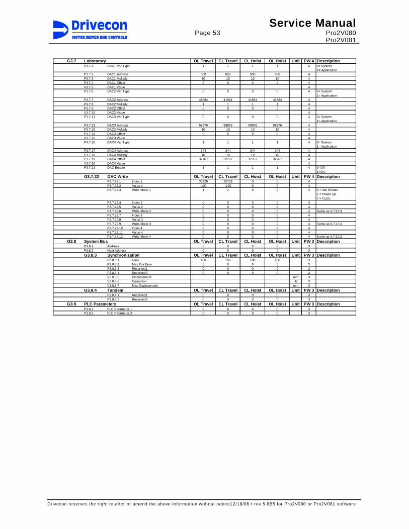
Page 53
Service Manual Pro2V080 Pro2V081
Drivecon reserves the right to al ter or amend the above information wi thout notice12/18/06 • rev 5.6B5 for Pro2V080 or Pro2V081 software
G3.7 Laboratory OL Travel CL Travel CL Hoist OL Hoist Unit PW 4 Descripti on
P3.7.1 DAC1 Var Type 1 1 1 1 4 0= System1= Application
P3.7.2 DAC1 Address 800 800 800 800 4P3.7.3 DAC1 Multiply 10 10 10 10 4P3.7.4 DAC1 Offset 0 0 0 0 4V3.7.5 DAC1 Value 4P3.7.6 DAC2 Var Type 0 0 0 0 4 0= System
1= ApplicationP3.7.7 DAC2 Address 41684 41684 41684 41684 4P3.7.8 DAC2 Multiply 1 1 1 1 4P3.7.9 DAC2 Offset 0 0 0 0 4V3.7.10 DAC2 Value 4P3.7.11 DAC3 Var Type 0 0 0 0 4 0= System
1= ApplicationP3.7.12 DAC3 Address 58976 58976 58976 58976 4P3.7.13 DAC3 Multiply 10 10 10 10 4P3.7.14 DAC3 Offset 0 0 0 0 4V3.7.15 DAC3 Value 4P3.7.16 DAC4 Var Type 1 1 1 1 4 0= System
1= ApplicationP3.7.17 DAC4 Address 344 344 344 344 4P3.7.18 DAC4 Multiply 10 10 10 10 4P3.7.19 DAC4 Offset 32767 32767 32767 32767 4V3.7.20 DAC4 Value 4P3.7.21 DAC Enable 1 1 1 1 4 0=Off
1=On
G3.7.22 DAC Write OL Travel CL Travel CL Hoist OL Hoist Unit PW 4 Descripti onP3.7.22.1 Index 1 35729 35729 0 0 4P3.7.22.2 Value 1 -100 -100 0 0 4P3.7.22.3 Write Mode 1 1 1 0 0 4 0 = Not Written
1 = Power-up2 = Cyclic
P3.7.22.4 Index 2 0 0 0 0 4P3.7.22.5 Value 2 0 0 0 0 4P3.7.22.6 Write Mode 2 0 0 0 0 4 Same as 3.7.22.3P3.7.22.7 Index 3 0 0 0 0 4P3.7.22.8 Value 3 0 0 0 0 4P3.7.22.9 Write Mode 3 0 0 0 0 4 Same as 3.7.22.3P3.7.22.10 Index 4 0 0 0 0 4P3.7.22.11 Value 4 0 0 0 0 4P3.7.22.12 Write Mode 4 0 0 0 0 4 Same as 3.7.22.3
G3.8 System Bus OL Travel CL Travel CL Hoist OL Hoist Unit PW 3 Descripti onP3.8.1 Address 0 0 0 0 3P3.8.2 Next Address 0 0 0 0 3
G3.8.3 Synchronization OL Travel CL Travel CL Hoist OL H oist Unit PW 3 DescriptionP3.8.3.1 Gain 100 100 100 100 3P3.8.3.2 Max Pos Error 0 0 0 0 3P3.8.3.3 Reserved1 0 0 0 0 3P3.8.3.4 Reserved2 0 0 0 0 3V3.8.3.5 Displacement mm 3V3.8.3.6 Correction Hz 3V3.8.3.7 Max Displacement mm 3
G3.8.4 Tandem OL Travel CL Travel CL Hoist OL Hoist Unit PW 3 Descripti onP3.8.4.1 Reserved1 0 0 0 0 3P3.8.4.2 Reserved2 0 0 0 0 3
G3.9 PLC Parameters OL Travel CL Travel CL Hoist OL Hoist Unit PW 3 Descripti onP3.9.1 PLC Parameter 1 0 0 0 0 3P3.9.2 PLC Parameter 2 0 0 0 0 3

Page 54
Service Manual Pro2V080 Pro2V081
Drivecon reserves the right to al ter or amend the above information wi thout notice12/18/06 • rev 5.6B5 for Pro2V080 or Pro2V081 software
6 COMPONENTS
6.1 Inverter Inverter (D2V) includes Power supply unit (PSU) and Control unit (CSU), which are separate parts. PSU includes supply, brake resistor and motor connections. IGBTs are located in the PSU. Microprocessors and ASIC are located in the CSU. The CSU is power class independent.
1min Frame Dimension Dimension Weight WeightD2V PSU CSU In Imax size mm (WxHxD) in (WxHxD) kg lbsD2V002NF1e04 PSU002NF1e1 CSU04 5.5 10 Fr4 128x339x190 5.04x13.35x7.48 6 13D2V003NF1e04 PSU003NF1e1 CSU04 8 12 Fr4 128x339x190 5.04x13.35x7.48 6 13D2V004NF1e04 PSU004NF1e1 CSU04 9 15 Fr4 128x339x190 5.04x13.35x7.48 6 13D2V005NF1e04 PSU005NF1e1 CSU04 12 20 Fr4 128x339x190 5.04x13.35x7.48 6 13D2V007NF1e04 PSU007NF1e1 CSU04 16 27 Fr5 144x434x214 5.67x17.09x8.43 10 22D2V011NF1e04 PSU011NF1e1 CSU04 22 36 Fr5 144x434x214 5.67x17.09x8.43 10 22D2V015NF1e04 PSU015NF1e1 CSU04 31 48 Fr6 195x561x237 7.68x22.09x9.33 20 44D2V018NF1e04 PSU018NF1e1 CSU04 38 63 Fr6 195x561x237 7.68x22.09x9.33 20 44D2V022NF1e04 PSU022NF1e1 CSU04 45 72 Fr6 195x561x237 7.68x22.09x9.33 20 44D2V030NF1e04 PSU030NF1e1 CSU04 61 90 Fr7 270x652x257 10.63x25.67x10.12 37 82D2V037NF1e04 PSU037NF1e1 CSU04 72 113 Fr7 270x652x257 10.63x25.67x10.12 37 82D2V045NF1e04 PSU045NF1e1 CSU04 87 135 Fr7 270x652x257 10.63x25.67x10.12 37 82D2V055NF1e04 PSU055NF1e1 CSU04 110 165 Fr8 355x832x340 13.98x32.76x13.39 61 135D2V075NF1e04 PSU075NF1e1 CSU04 150 225 Fr8 355x832x340 13.98x32.76x13.39 61 135D2V090NF1e04 PSU090NF1e1 CSU04 180 270 Fr8 355x832x340 13.98x32.76x13.39 61 135D2V110NF1e05 PSU110NF1e2 CSU05 210 315 Fr9 530x1350x362 20.87x53.15x14.25 120 265D2V132NF1e05 PSU132NF1e2 CSU05 245 368 Fr9 530x1350x362 20.87x53.15x14.25 120 265
1min Frame Dimension Dimension Weight WeightD2V PSU CSU In Imax size mm (WxHxD) in (WxHxD) kg lbsD2V002NK1e04 PSU002NK1e1 CSU04 3.2 5 Fr6 195x561x237 7.68x22.09x9.33 20 44D2V003NK1e04 PSU003NK1e1 CSU04 4.5 7 Fr6 195x561x237 7.68x22.09x9.33 20 44D2V004NK1e04 PSU004NK1e1 CSU04 5.5 9 Fr6 195x561x237 7.68x22.09x9.33 20 44D2V005NK1e04 PSU005NK1e1 CSU04 7.5 12 Fr6 195x561x237 7.68x22.09x9.33 20 44D2V007NK1e04 PSU007NK1e1 CSU04 10 15 Fr6 195x561x237 7.68x22.09x9.33 20 44D2V011NK1e04 PSU011NK1e1 CSU04 13.5 21 Fr6 195x561x237 7.68x22.09x9.33 20 44D2V015NK1e04 PSU015NK1e1 CSU04 18 27 Fr6 195x561x237 7.68x22.09x9.33 20 44D2V018NK1e04 PSU018NK1e1 CSU04 22 33 Fr6 195x561x237 7.68x22.09x9.33 20 44D2V022NK1e04 PSU022NK1e1 CSU04 27 41 Fr6 195x561x237 7.68x22.09x9.33 20 44D2V030NK1e04 PSU030NK1e1 CSU04 34 51 Fr7 270x652x257 10.63x25.67x10.12 37 82D2V037NK1e04 PSU037NK1e1 CSU04 41 62 Fr7 270x652x257 10.63x25.67x10.12 37 82D2V045NK1e04 PSU045NK1e1 CSU04 52 78 Fr8 355x832x340 13.98x32.76x13.39 61 135D2V055NK1e04 PSU055NK1e1 CSU04 62 93 Fr8 355x832x340 13.98x32.76x13.39 61 135D2V075NK1e04 PSU075NK1e1 CSU04 80 120 Fr8 355x832x340 13.98x32.76x13.39 61 135D2V090NK1e05 PSU090NK1e2 CSU05 100 150 Fr9 530x1350x362 20.87x53.15x14.25 120 265D2V110NK1e05 PSU110NK1e2 CSU05 125 188 Fr9 530x1350x362 20.87x53.15x14.25 120 265D2V132NK1e05 PSU132NK1e2 CSU05 144 216 Fr9 530x1350x362 20.87x53.15x14.25 120 265D2V160NK1e05 PSU160NK1e2 CSU05 170 255 Fr9 530x1350x362 20.87x53.15x14.25 120 265
e defines the power supply network ( 0 = unlimited or IT network, N = limited or grounded Y network )

Page 55
Service Manual Pro2V080 Pro2V081
Drivecon reserves the right to al ter or amend the above information wi thout notice12/18/06 • rev 5.6B5 for Pro2V080 or Pro2V081 software
The main circuit diagram of XTx4004 – XTx4022 and X Tx5005 – XTx5022
L1
L2
L3
DC-
DC+
BR B+ B-
U/T1
V/T2
W/T3
WH_G
WH_D
WL_G
WL_D
VH_G
VH_D
VL_D
UL_G
UL_D
BRK_G
BRK_D
UH_D
UH_G
VL_G
The main circuit diagram of XTx4031 – XTx4245 and X Tx5027 – XTx5170
DC-
DC+
BR B+ B-
WH_G
WH_D
WL_D
VH_G
VH_D
VL_G
VL_D
BRK_G
BRK_D
U/T1
V/T2
W/T3
L1
L2
L3
UH_D
UH_G
UL_G
UL_D
WL_G

Page 56
Service Manual Pro2V080 Pro2V081
Drivecon reserves the right to al ter or amend the above information wi thout notice12/18/06 • rev 5.6B5 for Pro2V080 or Pro2V081 software
6.1.1 Power supply unit (PSU) The power supply unit (PSU) includes the main circuit components. PSU has connectors for supply cables, motor cables and braking resistor cables. PSU also includes a 24 pin D-connector for connecting to the CSU. Main supply voltage terminals L1 Mains L1 L2 Mains L2 L3 Mains L3 PE Protective earth DC-bus and Braking Resistor terminals B- External DC-bus negative B+ External DC-bus positive / Brake resistor positive R- Brake resistor negative Motor output voltage terminals U/T1 Motor U V/T2 Motor V W/T3 Motor W
6.1.2 Control unit (CSU) The control unit (CSU) includes a control board with five board slots for option boards and a control keypad for parameter adjustments. CSU is normally connected to PSU through a D-connector. In special applications the CSU is connected to PSU with an fiber optic cables. The CSU can be powered with an external power supply (24Vdc). Control board LED indications Yellow Red Status blinking 0.5Hz
blinking 0.5Hz
Everything is OK. IEC Application Scheduler is running and Application is running
blinking 0.25Hz
blinking 0.5Hz
IEC Application Scheduler is running and Application is NOT running
OFF blinking 0.5Hz
IEC Application Scheduler and Application are NOT running
Green Status ON PSU ready
OFF PSU not ready
YELLOWRED
GREEN KEYPAD
A B C D E

Page 57
Service Manual Pro2V080 Pro2V081
Drivecon reserves the right to al ter or amend the above information wi thout notice12/18/06 • rev 5.6B5 for Pro2V080 or Pro2V081 software
6.1.3 Basic I/O board (Slot A) The basic I/O-Board is always included in CSU slot A. It has two board levels, one for electronics level signals (terminals 1-10) and one for control voltage signals (11-18). D2V- I/O_BOARD Terminal Signal name Description
1 PUR Output, pull up resistor, maximum current 10mA 2 +15 V Output +15Vdc, maximum current 50mA 3 AIN1+ Analog input 1 (0-10V) 4 AIN2+ Analog input 2 (–10V-+10V) 5 AIN- Common for analog input and output signals 6 AOUT1 Analog output 1 (0-20mA; Rcmax=500Ω) 7 AOUT2 Analog output 2 (0-10V) 8 DOA1 Digital output, open collector output 48V 50mA 9 0V I/O ground terminal
10 +24V +24Vdc output, maximum current 200mA
11 S1 Digital input 42-240Vac 50/60Hz (Direction S1) 12 S2 Digital input 42-240Vac 50/60Hz (Direction S2) 13 DIA3 Digital input 42-240Vac 50/60Hz 14 DIA4 Digital input 42-240Vac 50/60Hz 15 DIA5 Digital input 42-240Vac 50/60Hz 16 OK Digital input 42-240Vac 50/60Hz (OK-signal).
- OK-input is connected straight to the ASIC. - Inverter is ready to operate when OK-signal is active “1”.
17 COM Common for 42-240Vac 50/60Hz 18 COM Common for 42-240Vac 50/60Hz
The threshold voltage for digital inputs S1, S2, DIA3, DIA4, DIA5 and OK is 35VAC, 15mA.
1 2 3 4 5 6 7 8 9 10
11 12 13 14 15 16 17 18

Page 58
Service Manual Pro2V080 Pro2V081
Drivecon reserves the right to al ter or amend the above information wi thout notice12/18/06 • rev 5.6B5 for Pro2V080 or Pro2V081 software
6.1.4 Relay / Thermistor board (Slot B) Relay / Thermistor board is always included in CSU slot B. D2V-NXOPTA3 Terminal Signal name Description
21 ROB1 22 ROB1 23 ROB1
Relay output, 250V 8A
25
ROB2
26 ROB2
Relay output, 250V 8A, normal open
28 T1
29 T2
Thermistor or Klixon input, double isolated Rtr ip=4.7kohms
25 2621 22 23 28 29
6.1.5 SSU Speed Supervision board (Slot C) SSU is always included in CSU slot C for applications requiring speed feedback. D2V-SSU Terminal Signal name Description
1 EA+ Threshold voltage 10VDC 2 EA- Threshold voltage 10VDC 3 EB+ Threshold voltage 10VDC 4 EB- Threshold voltage 10VDC
5 +24V +24VDC short circuit protected
6 0V Common for encoder supply
28
ROC1
29 ROC1
Relay output, 250V 8A, normal open
- Relay contact ROC1 closes when inverter is powered and no
faults occurs - Relay contact ROC1 opens if the SSU has tripped in:
- Overspeed - Speed difference - Zero speed - Relay test fault - Watch dog fault
LED Blinking Status Red 1Hz OK Yellow 0.25Hz OK Yellow 4Hz Board internal fault or communication
fault with control unit
1 2 3 4 5 6
S1
S2
S3 RED
YELLOW
28 29

Page 59
Service Manual Pro2V080 Pro2V081
Drivecon reserves the right to al ter or amend the above information wi thout notice12/18/06 • rev 5.6B5 for Pro2V080 or Pro2V081 software
6.1.6 I/O Extension board (Slot D) I/O-extension board is normally included in CSU slot D. D2V-NXOPTB9 Terminal Signal name Description
1 DID1 42-240VAC 50/60Hz 2 DID2 42-240VAC 50/60Hz 3 DID3 42-240VAC 50/60Hz 4 DID4 42-240VAC 50/60Hz 5 DID5 42-240VAC 50/60Hz 6 COM Common for DID1-DID5
7
ROD1
8 ROD1
Relay output, 250V 8A, normal open
The threshold voltage for digital inputs DID1-DID5 is 35VAC, 15mA. LED Blinking Status Yellow 0.25Hz OK Yellow 4Hz Board internal fault or communication
fault with control unit
YELLOW
1 2 3 4 5 6 7 8
6.1.7 Relay Extension board (Slot E) Relay extension board is an optional board in CSU slot E, when additional relay functionality is needed. Functions of these relay outputs are programmable and are determined for each application. D2V-NXOPTB5 Terminal Signal name Description
22
ROE1
23 ROE1
Relay output, 250V 8A, normal open
25
ROE2
26 ROE2
Relay output, 250V 8A, normal open
28
ROE3
29 ROE3
Relay output, 250V 8A, normal open
LED Blinking Status Yellow 0.25Hz OK Yellow
4Hz
Board internal fault or communication fault with control unit
25 26 28 2925 26
YELLOW

Page 60
Service Manual Pro2V080 Pro2V081
Drivecon reserves the right to al ter or amend the above information wi thout notice12/18/06 • rev 5.6B5 for Pro2V080 or Pro2V081 software
6.1.8 Profibus board (Slot E) Profibus board can be optionally included in CSU slot E. The board has the 9-pin female D-connector for the Profibus cable connector. The connector signals are shown in the following table. D2V-NXOPTC5 Terminal Signal name Description
1 Shield Cable shield 3
RxD/TxD-P
Receive/Transmit data – plus (B = red wire)
5
DGND
Data Ground (reference potential for VP)
6
VP
Supply voltage – plus (5V)
8
RxD/TxD-N
Receive/Transmit data – minus (A = green wire)
The shield of the Prof ibus cable can be grounded in two different ways in the board: directly to the drive frame or to the frame of the drive through a RC filter. The selection of grounding the bus cable shield is done with the jumper X1. The default setting is the direct grounding. The default position of jumper X1 is shown in the figure to the right. Jumpers X4 and X6 are for the bus termination. The default position for the jumpers is shown in the figure to the right.
X4X6
X1
RE
DY
ELL
OW
GR
EE
N
The three LED indicators on the board are located next to the bus connector. In the normal Profibus communication the red LED is OFF, the yellow LED is blinking once a second and the green LED is also blinking once a second. Red LED Profibus status OFF Profibus communicates normally
- normal data exchange between Master and Slave ON Profibus communication is broken or not started
- Profibus cable broken or incorrectly connected - incorrect configuration or programmed data of Profibus master - Profibus master is off line or shut down
Yellow LED Status of Profibus option board OFF Option board not activated ON Option board in initialization state waiting for activation command from the drive
control unit Blinking fast 1Hz
Option board is activated and in RUN state, ready for external communication
Blinking slow 0.2Hz
Option board is activated and in FAULT state (an internal fault of option board)
Green LED Communication status OFF Profibus board is waiting for the parameters from the drive control unit, no
external communication ON Profibus board is activated: the parameters received from the drive control unit
and the board is waiting for messages from the Profibus master Blinking fast 1Hz
Profibus board is activated and receiving messages f rom the Profibus master
Blinking slow 0.2Hz
Profibus board is in a FAULT state - no messages f rom Profibus master within the watchdog time - Profibus cable broken, cable loose or Prof ibus master off l ine

Page 61
Service Manual Pro2V080 Pro2V081
Drivecon reserves the right to al ter or amend the above information wi thout notice12/18/06 • rev 5.6B5 for Pro2V080 or Pro2V081 software
6.2 Reference potentiometer A special potentiometer connection is used with the XT Series drive. End terminals of the potentiometer are shorted together and connected to the +10V terminal which is on the A board pin #5. The power supply is connected v ia a series resistor to the A board pin #1. The wiper of the potentiometer must be connected to the A board pin #3. Note that if several drives are controlled by a single potentiometer the power supply must be taken from only one of those drives. The impedance of the Ain1 input is about 200kohms, so the Ain1 inputs of the other drives can be connected in parallel (maximum four at a time). The inputs should be wired permanently parallel to maintain constant impedance. P3.2.2.3, P3.2.2.4, P3.2.2.5, P3.2.2.6, and P3.2.2.7 settings have an effect on the frequency reference FREF. See examples below, where Ain1 is voltage at the A board pin #3.
Speed Ain1 P3.2.2.3 P3.2.2.4 F REF The default values
min 10.0V 10.000 V 0.000 0% P3.2.2.3 = 10.000 V max 0V 10.000 V 0.000 100% P3.2.2.4 = 6.700 V
min 10.0V 10.000 5.000 0% P3.2.2.5 = 50.00 Hz max 5.0V 10.000 5.000 100% P3.2.2.6 = 0
min 10.0V 10.000 6.700 0% P3.2.2.7 = 0.10s max 6.7V 10.000 6.700 100%
XT series drives can be used with a custom-designed potentiometer, which structure is shown beside. The resistance between the end terminals of the potentiometer is 10kohms. The active region of the potentiometer is only about 180 degrees, but the length of the resistive element is about 340 degrees. In the middle of the normally unused 180 degrees region, there is a non-conducting gap. When the end terminals are shorted together, the resistance measured between the end terminals and the wiper varies from 2.5-2.8kohms (wiper in the middle, corresponds to minimum speed) to less than 800 ohms (wiper close to end terminal, corresponds to maximum speed). With the potentiometer joystick and default parameter values, the voltage level at the Ain1-input ranges from 10 to 6.7 volts (from 0 to 100% speed). Also any other potentiometer-controller combination can be used provided that P3.2.2.3, P3.2.2.4, P3.2.2.5, P3.2.2.6, and P3.2.2.7 setting range are sufficient.
10 kohm
CONNECTION TO AIN1+ X1:23
UNUSEDREGION
ENDTERMINAL
ENDTERMINAL
MOVINGCONTACT(WIPER)
CONNECTION TO AIN− X1:25
Potentiometer construction
0
2
4
6
8
10
12
-90 -60 -30 0 30 60 90
Turning angle of potentiometer / °
Voltage Speed
80%
100%
60%
40%
20%
Speed Voltage / V
Control voltage and speed as a function of turning angle.
21 23 25
AIN−AIN1+PUR
1k31
+ 15V
REFERENCE
Connection

Page 62
Service Manual Pro2V080 Pro2V081
Drivecon reserves the right to al ter or amend the above information wi thout notice12/18/06 • rev 5.6B5 for Pro2V080 or Pro2V081 software
6.3 Speed sensors
6.3.1 Encoder An incremental encoder can be used with XT Series drives to obtain excellent speed accuracy and fast response as well as to reach very low minimum speeds for precise positioning. The encoder signal is also used for speed superv ision purposes. Standard encoder has 600 pulses per revolution. It is allowed to use 512, 1000, 1024, 1200, 2000 or 2048 ppr encoders depending on motor speed and cable length. Encoder connection examples are shown below. The power supply from the drive (+24V, 0V) is connected to the respective encoder terminals. Both input channels (EA, EB) of the drive are "floating" inputs to reach maximum immunity to noise. All signal wires (EA+, EA-, EB+, EB-) shall be included inside a single shielded cable. The power supply to the encoder may also be included in the same cable. Standard connection The positive and negative terminals of both channels (EA+, EA-, EB+, EB-) are connected to encoder outputs (A+, A-, B+, B-).
EA+
EB+
EA-
EB-
ENCODERA+
B+
A-
B-
+24V
0V
+24V
0V
D2H/D2C
B6
G
PE
TERMINAL BOX BRIDGE CUBICLES
PEPE
Alternative connection The positive terminals of both channels (EA+, EB+) are connected to encoder outputs (A+, B+). The negative terminals of both channels (EA-, EB-) are connected to 0V as close to the encoder as possible.
EA+
EB+
EA-
EB-
ENCODERA+
B+
A-
B-
+24V
0V
+24V
0V
D2H/D2C
B6
G
PE
TERMINAL BOX BRIDGE CUBICLES
CHANNELS EA- AND EB-CONNECTED TO 0VIN MOTOR JUNCTION BOX
PEPE
OUTPUTSA- AND B- NOTCONNECTED
In many encoders, there are also "zero outputs (Z+, Z-)", which should be lef t disconnected. Signal outputs may also be labeled as 1, 1 , 2, 2 , 0 and 0. If the encoder does not have negative channels (A- and B-), EA- and EB- must be connected to 0V at motor terminal box (alternative connection).
In order to avoid fault situations, the cable between the encoder and the drive must be - as far as possible from the cables of motor and braking resistor (minimum distance >20cm) - a braided shielded and twisted pair cable - the shield must at both ends, 360 degree grounding at each interconnect point
- the shield should always be grounded always when going through terminals Some problems may occur when using shielded flat cable or in situations where the encoder cable has been placed too close (< 5cm) to the motor cables and braking resistor cables.

Page 63
Service Manual Pro2V080 Pro2V081
Drivecon reserves the right to al ter or amend the above information wi thout notice12/18/06 • rev 5.6B5 for Pro2V080 or Pro2V081 software
6.3.2 Bearing Sensor The drive needs information about the motor rotation speed for stall, speed difference and overspeed superv ision. Order codes of the bearing sensors are shown in the table below.
Motor type Motor code
Pulses per revolution
Order code Supply voltage
Max load
MF10MA200 T1 32 NM768NR3 24V DC 20 mA MF10MB200 T2 32 NM768NR3 24V DC 20 mA MF10MC200 T3 32 NM768NR3 24V DC 20 mA MF11MA200 T4 64 NM768NR4 24V DC 20 mA MF11MB200 T5 64 NM768NR4 24V DC 20 mA MF13Z-200 T6 80 NM768NR5 24V DC 20 mA MF13ZA200 T7 80 NM768NR5 24V DC 20 mA MF13ZB200 T8 80 NM768NR5 24V DC 20 mA MF13ZC200 T9 80 NM768NR5 24V DC 20 mA MF13X-200 TA 80 NM768NR5 24V DC 20 mA
Sensor bearing requires KAE234 buffer amplifier. If channel A+ is damaged, channel B+ can be used instead in emergency situations.
Signal name Sensor bearing wire colour
Terminal number
+24V Red KAE234:6 0V Black KAE234:2 A+ White KAE234:1 B+ Blue not connected
3
4
7
6
1
2
OUT
+ 24V
0V
:55
:51
:56
X1
+24V
EA+
0V
INVE
RTE
R
WHITE
BLACK
+ 24V
A
0V
RED
:52EA-
WHITE
GREEN
BROWN
Warning! Critical damage if: The supply voltage is over 28V or a short circuit between the
signal and the supply, or induction heating or hamm er mounting. In case of sensor damage, the entire motor must be changed.
Note the following details - buf fer amplifier must be located as close to the sensor bearing as possible (maximum
distance 2.5m) - bearing sensor signal cable must be located as far from the motor cables and braking
resistor cables as possible (minimum distance >20cm) In order to avoid fault situations, the cable between the buffer amplifier and the drive must be - as far as possible f rom the cables of motor and braking resistor (minimum distance >20cm) - a braided shielded and twisted pair cable - grounded (the shield) at both ends, 360 degree grounding on the drive terminal
- the shield should be grounded always when going through terminals

Page 64
Service Manual Pro2V080 Pro2V081
Drivecon reserves the right to al ter or amend the above information wi thout notice12/18/06 • rev 5.6B5 for Pro2V080 or Pro2V081 software
6.3.3 Proximity switch The drive needs information about the motor rotation speed for stall, speed difference and overspeed superv ision. Type markings of the speed superv ision sensors (not needed in applications with encoder or bearing sensor) and fixing distance from the pulse wheel (air gap) are shown in the table below. Proximity switch air gap
Honeywell 3GT101DC 0.5 ... 1.0 mm
Schönbuch INSOR88 ICDM 8802 0.5 ± 0.1 mm
Baumer IFRM08N1501/L 0.5 ± 0.1 mm
Baumer IFRM08N1501/S35L 0.5 ... 1.0 mm
Pulse wheel teeth numbers have been standardized according to the motor rotation speed, although other teeth numbers can be used (see table below).
Motor synchronous speed
Standard teeth number
Other allowed teeth numbers
3600 24 18
Honeywell 3GT101DC
5
12
35
29
3000 24 18 1800 24 18, 36, 48 1500 24 36, 48, 54 1200 36 24, 48, 54, 72 1000 36 48, 54, 72 900 48 36, 54, 72 750 48 54, 72 600 72 48, 54 500 72 -
40
8
Schönbuch INSOR ICDM 8802
Note that the Honeywell-sensor cable is lengthened and the wire colors are not the same as other sensors. However, color markings corresponding to the other sensors have been added to wire ends (not necessarily, if cable has been shortened afterwards). The connection of Honeywell-sensor and the cable markings are shown in the table below.
Signal name
Sensor Cable Colour marking
Terminal number
+24V Red Brown Brown KAE234:6
PULSE Green Green Black KAE234:1
0V Black White Blue KAE234:2
M8x1
30
Baumer IFRM08N1501/LBaumer IFRM08N1501/S35L
M8x1
50
35
The speed superv ision sensor connection to the buffer amplifier KAE234 is performed as follows:
Red
Green
Black
Brown
Green
White
6
1
2
3
4
7
+ V
0V
+ V
OUT
0V
Honeywell 3GT101DC
A5Brown
Black
Blue
6
1
2
3
4
7
+ V
0V
+ V
OUT
0V
A5
Schönbuch INSOR ICDM 8802Baumer IFRM08N1501/LBaumer IFRM08N1501/S35L
INVE
RTE
R
+ 24V
EA+
0V
EA-
PE

Page 65
Service Manual Pro2V080 Pro2V081
Drivecon reserves the right to al ter or amend the above information wi thout notice12/18/06 • rev 5.6B5 for Pro2V080 or Pro2V081 software
Note the following details - buffer amplifier must be located as close to the proximity switch as possible (maximum
distance 3m) - sensor cable must be located as far from the motor cables and braking resistor cables as
possible (minimum distance >20cm)
In order to avoid fault situations, the cable between the buffer amplifier and the drive must be - as far as possible from the cables of motor and braking resistor (minimum distance >20cm) - a braided shielded and twisted pair cable - grounded (the shield) at both ends, 360 degree grounding on the drive terminal
- the shield should be grounded always when going through terminals Some problems have occurred when using a shielded flat cable, or in the situations when the sensor cable has been placed too close (< 5cm) to the motor cables. Cabling methods and distances determine the best way to ground the shielded cable; at both ends or only at one end. Buffer amplifier pulse output can be measured during running. If the pulse sequence is not uniform and for instance longer pulses occur every now and then, the reason may be one of following:
- an incorrect air gap (proximity switch) - the sensor is not properly on the top of the pulse wheel (proximity switch) - disturbances are transferred to the sensor cable - the pulse wheel is faulty
Honeywell 3GT101DC Hall-sensor requires tooth movement past the sensor. A motionless tooth can not generate a pulse.
6.3.4 Buffer amplifier KAE234 The speed sensor (proximity switch or bearing sensor) is connected to the drive via a KAE234 buffer amplifier. KAE234 must be located near the sensor (usually in the connection box of the hoist or the motor). Without a buffer amplifier some faulty pulses could activate a speed superv ision fault in the drive. Typically the problem would be a momentary lack of pulses or oscillations at the sensor output. Usually the noise sensitivity increases when the sensor temperature rises.
KAE234 connection with a speed sensor.
3
4
7
6
1
2
OUT
+ 24V
0V
:55
:51
:56
X1
+24V
EA+
0V
INVE
RTE
R
+ 24V
OUT
0V
:52EA-
79
69 20
1 2
3 4
5 6
7 8
The dimensions shown above are in
mil limeters.
Buffer amplif ier pulse output can be measured during running. The picture beside presents the pulse output.
0± 1V
24V± 1V
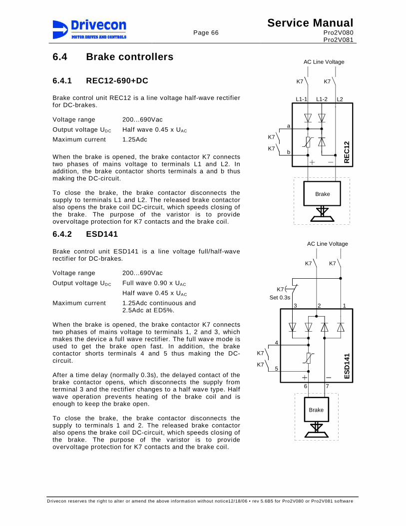
Page 66
Service Manual Pro2V080 Pro2V081
Drivecon reserves the right to al ter or amend the above information wi thout notice12/18/06 • rev 5.6B5 for Pro2V080 or Pro2V081 software
6.4 Brake controllers
6.4.1 REC12-690+DC Brake control unit REC12 is a line voltage half-wave rectifier for DC-brakes. Voltage range 200...690Vac
Output voltage UDC Half wave 0.45 x UAC
Maximum current 1.25Adc
When the brake is opened, the brake contactor K7 connects two phases of mains voltage to terminals L1 and L2. In addition, the brake contactor shorts terminals a and b thus making the DC-circuit. To close the brake, the brake contactor disconnects the supply to terminals L1 and L2. The released brake contactor also opens the brake coil DC-circuit, which speeds closing of the brake. The purpose of the varistor is to provide overvoltage protection for K7 contacts and the brake coil.
6.4.2 ESD141 Brake control unit ESD141 is a line voltage full/half-wave rectif ier for DC-brakes. Voltage range 200...690Vac
Output voltage UDC Full wave 0.90 x UAC
Half wave 0.45 x UAC
Maximum current 1.25Adc continuous and 2.5Adc at ED5%.
When the brake is opened, the brake contactor K7 connects two phases of mains voltage to terminals 1, 2 and 3, which makes the device a full wave rectif ier. The full wave mode is used to get the brake open fast. In addition, the brake contactor shorts terminals 4 and 5 thus making the DC-circuit. After a time delay (normally 0.3s), the delayed contact of the brake contactor opens, which disconnects the supply from terminal 3 and the rectifier changes to a half wave type. Half wave operation prevents heating of the brake coil and is enough to keep the brake open. To close the brake, the brake contactor disconnects the supply to terminals 1 and 2. The released brake contactor also opens the brake coil DC-circuit, which speeds closing of the brake. The purpose of the varistor is to provide overvoltage protection for K7 contacts and the brake coil.
L2L1-1 L1-2
a
b
K7
Brake
K7
K7
RE
C12
AC Line Voltage
K7
123
4
5
6 7
K7
K7Set 0.3s
Brake
K7
K7
ES
D14
1
AC Line Voltage
K7

Page 67
Service Manual Pro2V080 Pro2V081
Drivecon reserves the right to al ter or amend the above information wi thout notice12/18/06 • rev 5.6B5 for Pro2V080 or Pro2V081 software
7 TROUBLESHOOTING
This chapter describes how to detect and correct drive faults. The purpose is to find out which components are causing the fault and how to replace or correct them to restore proper operation.
7.1 Field repair actions The purpose of troubleshooting and field repair actions is primarily to determine whether the problems are in fact caused by the drive or external devices. After that, the next step is to detect the possibly damaged components inside the drive. If any damage inside drive is caused by the environment (motor failure, brake failure, power supply problems etc.) it is very important to repair/change faulty items to prevent further damage. The best way to repair a faulty inverter is to replace it with a new one. If the fault can be located, it is also possible to replace some of the inverter components. Always, if any power component inside the inverter is damaged, it is highly recommended to change the component that controls the damaged component. In the smallest models, replacing components except for the PC-boards is not recommended because of cost. When replacing an inverter or a PC-board with a new one, the parameter list of the existing drive configuration is needed so that the parameter settings can be copied from the existing drive. If parameters have been copied to the keypad before damage, it may be used for uploading the parameters to the spare or replacement inverter (requires same software versions).
Warning! High voltages inside the device. Wait for at least five minutes after the supply voltage has been switched off before performing any service actions. The display in the operating condition (lights on) indi cates a dangerous voltage on the DC-bus. When display turns off, the DC-bus volt age is approximately 100V. Note also that there is always a dangerous voltage in the braking resistor when the DC-bus is charged.

Page 68
Service Manual Pro2V080 Pro2V081
Drivecon reserves the right to al ter or amend the above information wi thout notice12/18/06 • rev 5.6B5 for Pro2V080 or Pro2V081 software
7.2 Inverter fault codes If any of the following faults occur, the drive displays the fault code and closes the mechanical brake causing the movement to stop. If several faults occur one after another, the latest one is displayed, the others are stored in the fault history. When the drive’s fault supervision trips, the FAULT indicator turns on and the blinking fault code “F xx“ (xx = fault number) appears on the display. The XT Series drives include an automatic fault reset operation; the fault code stays on the display unti l the fault is removed and the controller released back to 0-position. Some of the fault codes require to switch the power off before run is possible. The faults are stored in the drive’s fault history; from there they can be accessed if necessary. The fault history stores the 30 most recent fault codes. Following exceptions exist when storing faults to the fault history 1. not stored faults: F6, F70 2. repeated faults are stored only once: F50, F51, F55, F60, F66, F71, F72
Fault code Possible cause Checking
F 1 Overcurrent
Inverter has measured too high current (over 4*In peak) in the motor output: - sudden heavy load increase - short circuit in the motor or cable - not suitable motor - wrong motor parameters
Reset: switch power off and restart after the lamps of keypad are off. Check: - motor cable connection - motor and motor cable insulation - brake operation - motor loading - motor type and power rating - parameters
F 2 Overvoltage
DC-bus voltage has exceeded 135% maximum level, 911Vdc (F-series), 1200Vdc (K-series) - supply voltage raised >1.35 x
Un (high overvoltage spikes at mains or not sinusoidal voltage wave form)
- deceleration time is too short
Reset has an additional 5 s time delay. Check: - adjust the deceleration time longer - measure main supply voltage level and
wave form while not running - motor insulation - motor cable insulation (phase-ground,
phase-phase) - braking resistor cable - braking resistor type and resistance - braking chopper operation
F 3 Earth fault
Current measurement has sensed unbalance in motor phase currents. Supervision level is 50% of inverter nominal current - not symmetric load - insulation failure in the motor or
the cables
Reset has an additional 5 s time delay. Check: - motor insulation - motor cable insulation (phase-ground,
phase-phase)
F 5 Charging switch
Charging switch is open when START command becomes active - interference fault - component failure
Check: - control unit and power unit connections - charging resistors If the fault comes again, change the control unit.
F 6 External Stop
Either the ES or RDY-signal has been tripped during run or SSU speed supervision unit has detect - overspeed supervision - stall supervision - speed difference supervision Fault is not stored into fault history.
Check: - ES and RDY external connections - brake operation - pulse sensor/encoder function and cabling - measure pulse sensor/encoder pulses
with graphical multimeter or scope - SSU settings and SSU relay operation

Page 69
Service Manual Pro2V080 Pro2V081
Drivecon reserves the right to al ter or amend the above information wi thout notice12/18/06 • rev 5.6B5 for Pro2V080 or Pro2V081 software
Fault code Possible cause Checking
F 7 Saturation trip
Very high overload or defective component
Reset: switch power off and restart after the lamps of keypad are off. Check: - motor and motor cable insulation - measure main circuit diodes and IGBT
transistors If the fault happens again, change the drive.
F8 System fault
System fault due to component failure or faulty operation. Subcodes: S1 = Feedback of motor voltage S4 = ASIC trip S5 = Disturbance in optical bus S6 = Feedback of charging switch S7 = Charging switch S8 = No power to driver card S9 = Power unit communication S10 = Power unit communication S11 = Power unit communication
Reset: switch power off and restart after the lamps of keypad are off. Check: - read fault extension code and contact
Drivecon If the fault happens again, change the drive.
F 9 Undervoltage
DC-bus voltage has dropped below 333Vdc (F-series), 460Vdc (K-series) - mains supply voltage interrupted - inverter fault can also cause an
undervoltage trip - external fault during run may
cause an undervoltage trip
In case of temporary supply voltage break, reset the fault and start again. Check mains input. - if mains supply is correct, an internal
failure has occurred - contact Drivecon
F 10 Input line supervision
One input line phase is missing or supply voltage is wrong
Check: - supply voltage - mains connection
F 11 Output phase supervision
Current supervision has sensed that one of the motor phases has no current
Check: - motor cable connections - measure motor phase currents and
compare to display value F 12 Braking chopper supervision
Braking chopper or braking resistor circuit has failed. Fault appears if - braking resistor is broken - braking chopper is broken - braking resistor is not installed
Reset: switch power off and restart after the lamps of keypad are off. Check: - braking resistor and cable resistance and
insulation resistance - measure braking transistor IGBT and free
wheeling diodes - if resistor is OK, then the chopper is
broken - contact Drivecon
F 13 Inverter undertemperature
Temperature of heat sink is below acceptable operating level -10°C (14°F)
Check - ambient temperature - cubicle heating - inverter cooling fan activation
(continuous / temperature limit) F 14 Inverter overtemperature
Temperature of heat sink is over acceptable operating level +90°C (194°F). Overtemperature warning is issued when the heat sink temperature exceeds +85°C (185°F)
Check: - ambient temperature - inverter cooling fan operation - cooling air f low through heat sink - heat sink is not dusty
F16 Motor overtemperature
Mathematical motor temperature model has detected motor overheating. Motor is overloaded.
Check: - motor load - if no overload exists, then check motor
temperature model parameters
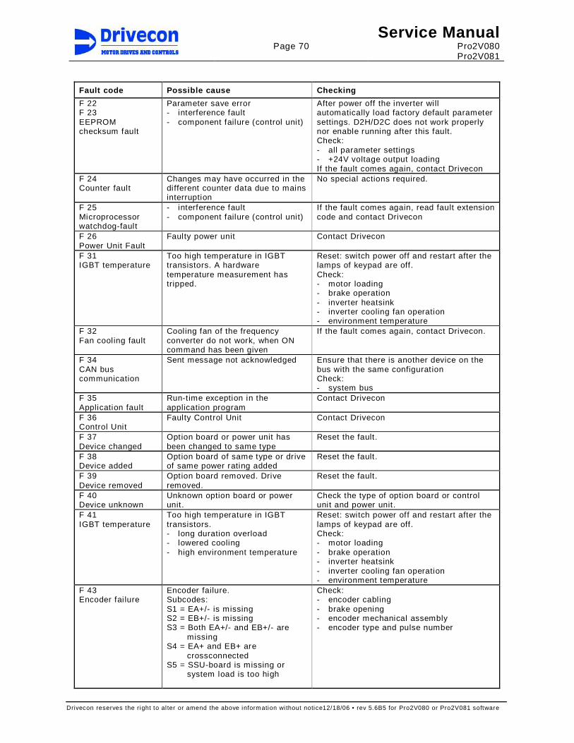
Page 70
Service Manual Pro2V080 Pro2V081
Drivecon reserves the right to al ter or amend the above information wi thout notice12/18/06 • rev 5.6B5 for Pro2V080 or Pro2V081 software
Fault code Possible cause Checking
F 22 F 23 EEPROM checksum fault
Parameter save error - interference fault - component failure (control unit)
After power off the inverter will automatically load factory default parameter settings. D2H/D2C does not work properly nor enable running after this fault. Check: - all parameter settings - +24V voltage output loading If the fault comes again, contact Drivecon
F 24 Counter fault
Changes may have occurred in the different counter data due to mains interruption
No special actions required.
F 25 Microprocessor watchdog-fault
- interference fault - component failure (control unit)
If the fault comes again, read fault extension code and contact Drivecon
F 26 Power Unit Fault
Faulty power unit Contact Drivecon
F 31 IGBT temperature
Too high temperature in IGBT transistors. A hardware temperature measurement has tripped.
Reset: switch power off and restart after the lamps of keypad are off. Check: - motor loading - brake operation - inverter heatsink - inverter cooling fan operation - environment temperature
F 32 Fan cooling fault
Cooling fan of the frequency converter do not work, when ON command has been given
If the fault comes again, contact Drivecon.
F 34 CAN bus communication
Sent message not acknowledged
Ensure that there is another device on the bus with the same configuration Check: - system bus
F 35 Application fault
Run-time exception in the application program
Contact Drivecon
F 36 Control Unit
Faulty Control Unit Contact Drivecon
F 37 Device changed
Option board or power unit has been changed to same type
Reset the fault.
F 38 Device added
Option board of same type or drive of same power rating added
Reset the fault.
F 39 Device removed
Option board removed. Drive removed.
Reset the fault.
F 40 Device unknown
Unknown option board or power unit.
Check the type of option board or control unit and power unit.
F 41 IGBT temperature
Too high temperature in IGBT transistors. - long duration overload - lowered cooling - high environment temperature
Reset: switch power off and restart after the lamps of keypad are off. Check: - motor loading - brake operation - inverter heatsink - inverter cooling fan operation - environment temperature
F 43 Encoder fai lure
Encoder failure. Subcodes: S1 = EA+/- is missing S2 = EB+/- is missing S3 = Both EA+/- and EB+/- are
missing S4 = EA+ and EB+ are
crossconnected S5 = SSU-board is missing or
system load is too high
Check: - encoder cabling - brake opening - encoder mechanical assembly - encoder type and pulse number

Page 71
Service Manual Pro2V080 Pro2V081
Drivecon reserves the right to al ter or amend the above information wi thout notice12/18/06 • rev 5.6B5 for Pro2V080 or Pro2V081 software
Fault code Possible cause Checking
F 44 Device changed
Option board or control unit has been changed to different type or different power rating
Reset the fault. Option board parameters or all parameters are set up to default values.
F 45 Device added
Option board of different type or drive of different power rating added
Reset the fault. Option board parameters or all parameters are set up to default values.
F 50 Reference value fault
Analog input signal is out of selected range 1-9V or 2-10V - control cable is broken - signal source has failed
Check - reference cable - reference source
F 51 Stop limit
Stop limit has tripped Reset: keep controller at zero >300ms. Ensure that fault disappears after leaving the stop l imit.
F 53 Profibus communication error
Watchdog time out in Profibus communication. Effective only if control through Profibus is selected. Poor Profibus cable connection or communication problems with Profibus master.
Reset: switch power off and restart after the lamps of keypad are off. Check: - Profibus slave address - Profibus cable connection - Profibus termination resistor settings
F 55 Board Fault
Some of fol lowing board is missing: - A = Basic I/O board - B = Thermistor board - C = SSU (in closed loop and
hoisting applications)
Reset: switch power off and restart after the lamps of keypad are off. Check - board slots A, B and C - drive selection - control mode
F 56 Generator side current limit
Open loop frequency control only. Too short deceleration time or open loop generator side current limit is too low.
Reset has an additional 5 s time delay. Check: - deceleration t ime - current l imit setting
F 57 Thermistor fault
Thermistor input in relay / thermistor board has detected motor overtemperature. Fault appears when thermistor input has been open over 1s.
Check: - motor cooling and loading - thermistor connection. If expansion board
thermistor input is not used, i t should be shorted
- motor parameters - the brake operation
F 60 Parameter fault
Inverter has lost parameters. Drive selection parameter has changed to 0 / none.
Download parameters from keypad
F 61 Overspeed Fault
SSU has tripped to Overspeed (hardware supervision). Motor speed has increased above overspeed detection level.
Resets when 1s without pulses from pulse sensor/encoder to SSU and control ler is at zero position. Check: - function and cabling - maximum frequency setting parameters - SSU settings
F 62 Speed Difference Fault
SSU has tripped to Speed Difference
Resets when 1s without pulses from pulse sensor/encoder to SSU and control ler is at zero position. Check: - pulse sensor/encoder function and cabling - pulse sensor/encoder pulse number - speed difference supervision settings
F 63 Stall Supervision Fault
SSU has tripped to Stall Resets when 1s without pulses from pulse sensor/encoder to SSU and control ler is at zero position. Check: - brake operation - pulse sensor/encoder function and cabling - stall supervision sett ings

Page 72
Service Manual Pro2V080 Pro2V081
Drivecon reserves the right to al ter or amend the above information wi thout notice12/18/06 • rev 5.6B5 for Pro2V080 or Pro2V081 software
Fault code Possible cause Checking
F 64 SSU Relay Test Fault
Relay in SSU board is damaged, SSU relay is bypassed or OK input is damaged.
Reset: switch power off and restart after the lamps of keypad are off. Check: - ES and RDY external connections - OK input operation - change SSU board
F 65 SSU Watchdog
SSU internal fault - interference fault between SSU
board and control board - component failure (control
board or SSU board)
Check: - SSU status (System menu / System info /
Expander boards / C: SSU / status) - SSU LED’s If the fault comes again, contact authorized service
F 66 SSU Overspeed Limit
SSU overspeed limit has been set over 140% of maximum frequency
Check: - set SSU overspeed limit under 140% of
maximum frequency - motor type plate parameters - maximum frequency parameters
F 70 Mult icare Fault
Other D2H/D2C has tripped to fault or brake of other D2H/D2C has not been opened. Fault is not stored into fault history.
Check other drive in tandem operation: - fault history - brake operation - brake relay control delay settings
F 71 Brake Control Fault
Brake operation is faulty or load information from load measuring device is out of operation window
Check - brake operation - Ain2 wiring - settings of load measuring device
F 72 Brake Feedback Fault
Brake is opening or closing in wrong time
Check: - brake operation - brake relay (ROB2) and brake contactor
(K7/K71) operation F 73 Both Dir Active
Both direction signals are active at same time >500 ms
Check: - controller operation - wiring of direction signals Brake closes immediately and speed is ramped down. If the fault happens at high speed, mechanical brake wears heavily.
F 74 Sway Control
Sway control calculation has tripped
Crane movement by sway control is prevented to ensure safety. Contact factory for more information.
F 75 Limit Test
One or all limit switches have failed in the test
Check: - limit switch operation - wiring of limit switches
F 76 Input Signal
Limit switch signals from terminals and Profibus are different
Check: - wiring of limit switches

Page 73
Service Manual Pro2V080 Pro2V081
Drivecon reserves the right to al ter or amend the above information wi thout notice12/18/06 • rev 5.6B5 for Pro2V080 or Pro2V081 software
7.2.1 Fault time data record When a fault occurs, the fault number is displayed. By pushing the cursor right button you will enter the Fault time data record menu, indicated by T.1-T.16. In this menu, some selected important data valid at the time of the fault is recorded. The data available is:
T.1 Counted operation days d T.2 Counted operation hours hh:mm:ss T.3 Output frequency Hz T.4 Motor current A T.5 Motor voltage V T.6 Motor power % T.7 Motor torque % T.8 DC voltage V T.9 Unit temperature °C
T.10 Ready Run
0=Not Ready 1=Ready 0=Not Running 1=Run
T.11 Direction Fault
0=Off 1=On 0=No 1=Yes
T.12 Warning At reference
0=No 1=Yes 0=No 1=Yes
T.13 0-speed 0=Not Zero Speed 1=Zero Speed
T.14 Subcode T.15 Module T.16 Submodule
7.2.2 Fault Counter When a fault occurs, the fault is recorded in a counter.
V4.5.1 F1 Overcurrent Overcurrent fault counter V4.5.2 F2 Overvoltage Overvoltage fault counter V4.5.3 F3 Earth Fault Earth fault counter V4.5.4 F7 Saturation Saturation trip fault counter V4.5.5 F9 Undervoltage Undervoltage fault counter V4.5.6 F10 Input Phase Input line supervision fault counter V4.5.7 F11 Output Phase Output phase supervision fault counter V4.5.8 F12 BrakeChopper Braking chopper supervision fault counter V4.5.9 F13 Undertemp Inverter undertemperature fault counter
V4.5.10 F14 Overtemp Inverter overtemperature fault counter V4.5.11 F31 IGBT Temp HW IGBT temperature fault counter V4.5.12 F41 IGBT Temp IGBT temperature fault counter V4.5.13 F43 Encoder Encoder fai lure fault caunter V4.5.14 F53 Profibus Profibus communication error fault counter V4.5.15 F56 Gen Curr Lim Generator side current l imit fault counter V4.5.16 F57 Thermistor Thermistor fault counter V4.5.17 F61 SSU Overspd Overspeed fault counter V4.5.18 F62 SSU Spd Diff Speed difference fault counter V4.5.19 F63 SSU Stall Stall supervision fault counter V4.5.20 F74 Sway Control Sway Control fault counter V4.5.21 F76 Input Signal Input Signal V4.5.22 A81 Brake Slip Brake Slip alarm counter V4.5.23 A82 Overweight Overweight alarm counter V4.5.24 Other faults Sum counter of fol lowing faults:
F4, F5, F8, F22, F23, F24, F25, F26, F32, F33, F34, F35, F36, F37, F38, F39, F40, F44, F45, F48, F50, F54, F55, F60, F64, F65, F71, F72, F73, F75
V4.5.25 Total Faults Total number of all faults.

Page 74
Service Manual Pro2V080 Pro2V081
Drivecon reserves the right to al ter or amend the above information wi thout notice12/18/06 • rev 5.6B5 for Pro2V080 or Pro2V081 software
7.3 Inverter Alarm codes Alarm is a sign of an unusual operating condition. Alarm remains in the display for about 10 seconds.
Alarm code Possible cause Checking
A 16 Motor overtemperature
Mathematical motor temperature model has detected motor overheating. Motor is overloaded.
Check: - motor load - if no overload exists, then check motor
temperature model parameters A 50 Reference value alarm
Analog input signal is out of selected range 1-9V or 2-10V - control cable is broken - signal source has failed
Check: - reference cable - reference source
A 80 Mult istep sequence alarm
Controller does not operate accurately
Check: - controller
A 81 Brake Slip
Inverter run command is off but motor is rotating
Don’t turn off the power before the load is safe on the ground. Check: - mechanical brake See section 4.6 of this manual for more information.
A 82 Overweight alarm
Motor load is over adjusted value
Check: - Overweight limit value
A 83 Slack cable alarm
Motor load is under adjusted value
Check: - Slack cable l imit value
A 84 SwCtrlLicens
One or both Sway Control Licence Keys are incorrect or missing
Check: - Licence Key numbers - Sway Control mode

Page 75
Service Manual Pro2V080 Pro2V081
Drivecon reserves the right to al ter or amend the above information wi thout notice12/18/06 • rev 5.6B5 for Pro2V080 or Pro2V081 software
8 SERVICE In the normal operation XT Series drives do not require regular maintenance. The following actions are recommended: 1.
Check the fault history of the inverter
- Find out reasons of possible faults - Record faults and clear the fault history
2.
Clean the heat sink of the inverter
- Prevent the dust to spread inside cubicles - Lock the fans before blowing compressed air
3.
Check that there are no abnormal noises coming from the cooling fans
4. Tighten all screws and connectors - Avoid too high tightening torques 5. Clean dust from PC-boards 6. Check the speed superv ision circuit - See section 4.3.1 Functional test run for SSU
8.1 DC-bus electrolytic capacitors Inverters have large aluminium electrolytic capacitors in DC-bus. In the normal operation the leakage current of the capacitor is low based on dielectric aluminium oxide layer (forming) on the foil. If the inverters or separate capacitors are stored a long period without applied voltage, the forming looses it’s homogeneous. When a long stored inverter is connected straight to mains voltage, a high leakage current can exist and damage the other inverter components.
8.1.1 Re-forming after a long storage period
Complete inverters regular maintenance
When the complete inverters are stored without voltage applied, the re-forming of the capacitors should be done at least once in a year. Connect the mains voltage into inverter and keep power on at least 1 h continuously.
Complete inverters re-forming after a long storage period
If much more than one year has elapsed since the inverter was energized last time, the re-forming of the capacitors has to be done in a way that the possible high leakage current through the capacitors is limited. Best alternative is to use a DC-power supply prov ided with an adjustable current limitation. Set current limit to 300…500 mA and connect DC-power supply straight to the inverter DC-bus terminals B+ and B-. Then adjust DC-voltage up to nominal DC-voltage level of the inverter (F-series: 675 VDC, K-series: 930 VDC) and keep power supplied at least 1h. If the DC-power supply is not available and the inverter has been stored much longer than 1 year de-energised, consult authorized serv ice before switching the power on.
Spare capacitors re-forming after a long storage pe riod
When using over one year old spare part capacitors from the stock, the re-forming is recommended to perform before capacitors are installed inside the inverter. For loose capacitors, set DC-power current limit to 50…100 mA. Then adjust DC-voltage up to the rated value of capacitors (F-series: 420 VDC, K-series: 550 VDC) and keep power supplied at least 1h. The degree of re-forming process can be followed on the current meter of the DC-power supply. If the re-forming is not done for the loose capacitors, the re-forming has to be done for a complete inverter according to above instruction of re-forming after a long storage period. Warning! Due to high leakage resistance the dangero us voltage can remain in capacitor a
long time. If the DC-power supply is not able to di ssipate the voltage after re-forming, discharge the capacitor by using a resisto r (minimum 100kohm 2W). Discharging will take several minutes and resistor will get hot. Measure the voltage before touching the capacitor terminals.

Page 76
Service Manual Pro2V080 Pro2V081
Drivecon reserves the right to al ter or amend the above information wi thout notice12/18/06 • rev 5.6B5 for Pro2V080 or Pro2V081 software
9 DRAWINGS