XPIP STC01015 Str'l Design Criteria
32
TECHNICAL CORRECTION February 2006 Process Industry Practices Structural PIP STC01015 Stru ctural Design Criteria FOR ACADEMIC USE ONLY
-
Upload
macynthia26 -
Category
Documents
-
view
26 -
download
0
description
Structural Design Guidelines
Transcript of XPIP STC01015 Str'l Design Criteria

7/18/2019 XPIP STC01015 Str'l Design Criteria
http://slidepdf.com/reader/full/xpip-stc01015-strl-design-criteria 1/32
TECHNICAL CORRECTION February 2006
Process Industry Practices
Structural
PIP STC01015Structural Design Criteria
FOR ACADEMIC USE ONLY

7/18/2019 XPIP STC01015 Str'l Design Criteria
http://slidepdf.com/reader/full/xpip-stc01015-strl-design-criteria 2/32
PURPOSE AND USE OF PROCESS INDUSTRY PRACTICES
In an effort to minimize the cost of process industry facilities, this Practice has
been prepared from the technical requirements in the existing standards of major
industrial users, contractors, or standards organizations. By harmonizing these technical
requirements into a single set of Practices, administrative, application, and engineering
costs to both the purchaser and the manufacturer should be reduced. While this Practice
is expected to incorporate the majority of requirements of most users, individual
applications may involve requirements that will be appended to and take precedence
over this Practice. Determinations concerning fitness for purpose and particular matters
or application of the Practice to particular project or engineering situations should not
be made solely on information contained in these materials. The use of trade namesfrom time to time should not be viewed as an expression of preference but rather
recognized as normal usage in the trade. Other brands having the same specifications
are equally correct and may be substituted for those named. All Practices or guidelines
are intended to be consistent with applicable laws and regulations including OSHA
requirements. To the extent these Practices or guidelines should conflict with OSHA or
other applicable laws or regulations, such laws or regulations must be followed.
Consult an appropriate professional before applying or acting on any material
contained in or suggested by the Practice.
This Practice is subject to revision at any time by the responsible Function Team and will
be reviewed every 5 years. This Practice will be revised, reaffirmed, or withdrawn.Information on whether this Practice has been revised may be found at www.pip.org.
© Process Industry Practices (PIP), Construction Industry Institute, The
University of Texas at Austin, 3925 West Braker Lane (R4500), Austin,
Texas 78759. PIP member companies and subscribers may copy this Practice
for their internal use. Changes, overlays, addenda, or modifications of any
kind are not permitted within any PIP Practice without the express written
authorization of PIP.
PIP will not consider requests for interpretations (inquiries) for this Practice.
PRINTING HISTORY
December 1998 Issued August 2004 Complete Revision
February 2002 Technical Revision February 2006 Technical Correction
April 2002 Editorial Revision
Not printed with State funds
FOR ACADEMIC USE ONLY

7/18/2019 XPIP STC01015 Str'l Design Criteria
http://slidepdf.com/reader/full/xpip-stc01015-strl-design-criteria 3/32
TECHNICAL CORRECTIONFebruary 2006
Process Industry Practices Page 1 of 30
Process Industry Practices
Structural
PIP STC01015
Structural Design Criteria
Table of Contents
1. Introduction.................................2 1.1 Purpose .............................................2 1.2 Scope................................................. 2
2. References ..................................2 2.1 Process Industry Practices (PIP)....... 2 2.2 Industry Codes and Standards..........2 2.3
Government Regulations...................4
3. Definit ions ...................................5
4. Requirements..............................5 4.1 Design Loads.....................................5 4.2 Load Combinations.......................... 14 4.3 Structural Design............................. 23 4.4 Existing Structures...........................30
FOR ACADEMIC USE ONLY
7/18/2019 XPIP STC01015 Str'l Design Criteria
http://slidepdf.com/reader/full/xpip-stc01015-strl-design-criteria 4/32
PIP STC01015 TECHNICAL CORRECTIONStructural Design Criteria February 2006
Page 2 of 30 Process Industry Practices
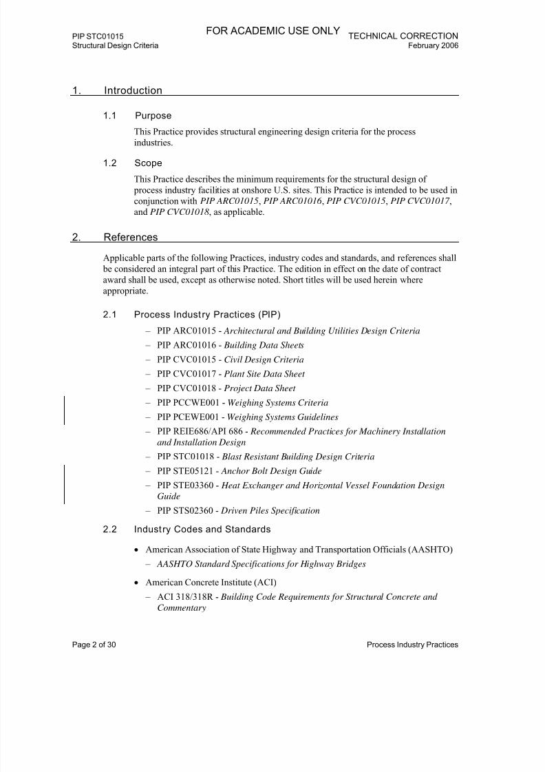
1. Introduction
1.1 Purpose
This Practice provides structural engineering design criteria for the processindustries.
1.2 Scope
This Practice describes the minimum requirements for the structural design of
process industry facilities at onshore U.S. sites. This Practice is intended to be used in
conjunction with PIP ARC01015, PIP ARC01016 , PIP CVC01015, PIP CVC01017 ,
and PIP CVC01018 , as applicable.
2. References
Applicable parts of the following Practices, industry codes and standards, and references shall be considered an integral part of this Practice. The edition in effect on the date of contract
award shall be used, except as otherwise noted. Short titles will be used herein where
appropriate.
2.1 Process Industry Practices (PIP)
– PIP ARC01015 - Architectural and Building Utilities Design Criteria
– PIP ARC01016 - Building Data Sheets
– PIP CVC01015 - Civil Design Criteria
– PIP CVC01017 - Plant Site Data Sheet
– PIP CVC01018 - Project Data Sheet
– PIP PCCWE001 - Weighing Systems Criteria
– PIP PCEWE001 - Weighing Systems Guidelines
– PIP REIE686/API 686 - Recommended Practices for Machinery Installation
and Installation Design
– PIP STC01018 - Blast Resistant Building Design Criteria
– PIP STE05121 - Anchor Bolt Design Guide
– PIP STE03360 - Heat Exchanger and Horizontal Vessel Foundation Design
Guide
– PIP STS02360 - Driven Piles Specification
2.2 Industry Codes and Standards
• American Association of State Highway and Transportation Officials (AASHTO)
– AASHTO Standard Specifications for Highway Bridges
• American Concrete Institute (ACI)
– ACI 318/318R - Building Code Requirements for Structural Concrete and
Commentary
FOR ACADEMIC USE ONLY

7/18/2019 XPIP STC01015 Str'l Design Criteria
http://slidepdf.com/reader/full/xpip-stc01015-strl-design-criteria 5/32
TECHNICAL CORRECTION PIP STC01015 February 2006 Structural Design Criteria
Process Industry Practices Page 3 of 30
– ACI 350R - Environmental Engineering Concrete Structures
– ACI 530/ASCE 5 - Building Code Requirements for Masonry Structures
• American Institute of Steel Construction (AISC)
– AISC Manual of Steel Construction - Allowable Stress Design (ASD) – AISC Manual of Steel Construction - Load and Resistance Factor
Design (LRFD)
– Specification for Structural Joints Using ASTM A325 or A490 Bolts
– ANSI/AISC 341-02 - Seismic Provisions for Structural Steel Buildings
• American Iron and Steel Institute (AISI)
– AISI SG 673, Part I - Specification for the Design for Cold-Formed Steel
Structural Members
– AISI SG 673, Part II - Commentary on the Specification for the Design for
Cold-Formed Steel Structural Members
– AISI SG 913, Part I - Load and Resistance Factor Design Specification for
Cold-Formed Steel Structural Members
– AISI SG 913, Part II - Commentary on the Load and Resistance Factor Design
Specification for Cold-Formed Steel Structural Members
• American Petroleum Institute (API)
– API Standard 650 - Welded Steel Tanks for Oil Storage
• American Society of Civil Engineers (ASCE)
– SEI/ASCE 7-02 - Minimum Design Loads for Buildings and Other Structures
– SEI/ASCE 37-02 - Design Loads on Structures During Construction
– ASCE Guidelines for Seismic Evaluation and Design of PetrochemicalFacilities
– ASCE Guidelines for Wind Loads and Anchor Bolt Design for Petrochemical
Facilities
– ASCE Design of Blast Resistant Buildings in Petrochemical Facilities
• American Society of Mechanical Engineers (ASME)
– ASME A17.1 - Safety Code for Elevators and Escalators
• ASTM International (ASTM)
– ASTM A36 / A36M - Standard Specification for Carbon Structural Steel
– ASTM A82/A82M - Standard Specification for Steel Wire, Plain, for Concrete Reinforcement
– ASTM A185/A185M - Standard Specification for Steel Welded Wire
Reinforcement, Plain, for Concrete
– ASTM A193/A193M - Standard Specification for Alloy-Steel and Stainless
Steel Bolting Materials for High-Temperature Service
FOR ACADEMIC USE ONLY

7/18/2019 XPIP STC01015 Str'l Design Criteria
http://slidepdf.com/reader/full/xpip-stc01015-strl-design-criteria 6/32
PIP STC01015 TECHNICAL CORRECTIONStructural Design Criteria February 2006
Page 4 of 30 Process Industry Practices
– ASTM A307 - Standard Specification for Carbon Steel Bolts and Studs, 60,000
psi Tensile Strength
– ASTM A325 - Standard Specification for Structural Bolts, Steel, Heat Treated,
120/105 ksi Minimum Tensile Strength - AASHTO No.: M 164
– ASTM A325M - Standard Specification for Structural Bolts, Steel, HeatTreated 830 MPa Minimum Tensile Strength [Metric]
– ASTM A354 - Standard Specification for Quenched and Tempered Alloy Steel
Bolts, Studs, and Other Externally Threaded Fasteners
– ASTM 490 - Standard Specification for Structural Bolts, Alloy Steel, Heat
Treated,150 ksi Minimum Tensile Strength - AASHTO No.: M 253
– ASTM A615/A615M - Standard Specification for Deformed and Plain
Carbon-Steel Bars for Concrete Reinforcement
– ASTM A706/A706M - Standard Specification for Low-Alloy Steel Deformed
and Plain Bars for Concrete Reinforcement
– ASTM A992/A992M - Standard Specification for Structural Steel Shapes – ASTM F1554 - Standard Specification for Anchor Bolts, Steel, 36, 55, and
105-ksi Yield Strength
• American Welding Society (AWS)
– AWS D1.1/D1.1M - Structural Welding Code - Steel
• American Forest and Paper Association
– National Design Specification for Wood Construction (NDS)
– NDS Supplement - Design Values for Wood Construction
• Crane Manufacturers Association of America (CMAA)
– CMAA No. 70 - Specifications for Top Running Bridge and Gantry Type
Multiple Girder Overhead Electric Traveling Cranes
– CMAA No. 74 - Specifications for Top Running and Under Running Single
Girder Overhead Electric Traveling Cranes Utilizing Under Running Trolley
Hoist
• Precast/Prestressed Concrete Institute (PCI)
– PCI MNL 120 - Design Handbook - Precast and Prestressed Concrete
• Steel Joist Institute (SJI)
– SJI Standard Specifications, Load Tables and Weight Tables for Steel Joists
and Joist Girders
2.3 Government Regulations
Federal Standards and Instructions of the Occupational Safety and Health
Administration (OSHA), including any additional requirements by state or local
agencies that have jurisdiction in the state where the project is to be constructed, shall
apply.
FOR ACADEMIC USE ONLY
7/18/2019 XPIP STC01015 Str'l Design Criteria
http://slidepdf.com/reader/full/xpip-stc01015-strl-design-criteria 7/32
TECHNICAL CORRECTION PIP STC01015 February 2006 Structural Design Criteria
Process Industry Practices Page 5 of 30
• U.S. Department of Labor, Occupational Safety and Health Administration
(OSHA)
– OSHA 29 CFR 1910 - Occupational Safety and Health Standards
– OSHA 29 CFR 1926 - Safety and Health Regulations for Construction
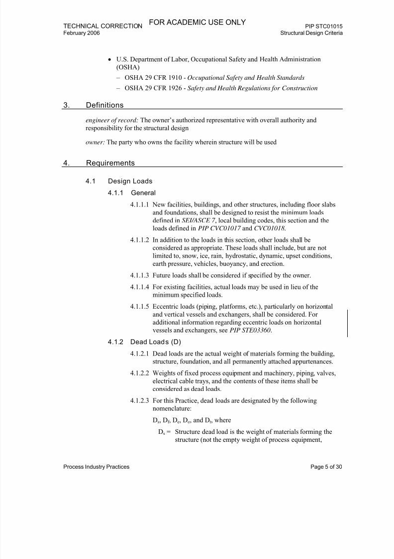
3. Definitions
engineer of record: The owner’s authorized representative with overall authority and
responsibility for the structural design
owner: The party who owns the facility wherein structure will be used
4. Requirements
4.1 Design Loads
4.1.1 General
4.1.1.1 New facilities, buildings, and other structures, including floor slabs
and foundations, shall be designed to resist the minimum loads
defined in SEI/ASCE 7 , local building codes, this section and the
loads defined in PIP CVC01017 and CVC01018 .
4.1.1.2 In addition to the loads in this section, other loads shall be
considered as appropriate. These loads shall include, but are not
limited to, snow, ice, rain, hydrostatic, dynamic, upset conditions,
earth pressure, vehicles, buoyancy, and erection.
4.1.1.3 Future loads shall be considered if specified by the owner.
4.1.1.4 For existing facilities, actual loads may be used in lieu of theminimum specified loads.
4.1.1.5 Eccentric loads (piping, platforms, etc.), particularly on horizontal
and vertical vessels and exchangers, shall be considered. For
additional information regarding eccentric loads on horizontal
vessels and exchangers, see PIP STE03360.
4.1.2 Dead Loads (D)
4.1.2.1 Dead loads are the actual weight of materials forming the building,
structure, foundation, and all permanently attached appurtenances.
4.1.2.2 Weights of fixed process equipment and machinery, piping, valves,
electrical cable trays, and the contents of these items shall beconsidered as dead loads.
4.1.2.3 For this Practice, dead loads are designated by the following
nomenclature:
Ds, Df , De, Do, and Dt, where
Ds = Structure dead load is the weight of materials forming the
structure (not the empty weight of process equipment,
FOR ACADEMIC USE ONLY

7/18/2019 XPIP STC01015 Str'l Design Criteria
http://slidepdf.com/reader/full/xpip-stc01015-strl-design-criteria 8/32
PIP STC01015 TECHNICAL CORRECTIONStructural Design Criteria February 2006
Page 6 of 30 Process Industry Practices
vessels, tanks, piping, nor cable trays), foundation, soil
above the foundation resisting uplift, and all permanently
attached appurtenances (e.g., lighting, instrumentation,
HVAC, sprinkler and deluge systems, fireproofing, and
insulation, etc.).
Df = Erection dead load is the fabricated weight of process
equipment or vessels (as further defined in Section 4.1.2.4).
De = Empty dead load is the empty weight of process equipment,
vessels, tanks, piping, and cable trays (as further defined in
Sections 4.1.2.4 through 4.1.2.6).
Do = Operating dead load is the empty weight of process
equipment, vessels, tanks, piping, and cable trays plus the
maximum weight of contents (fluid load) during normal
operation (as further defined in Sections 4.1.2.4
through 4.1.2.7).
Dt = Test dead load is the empty weight of process equipment,vessels, tanks, and/or piping plus the weight of the test
medium contained in the system (as further defined in
Section 4.1.2.4).
4.1.2.4 Process Equipment and Vessel Dead Loads
1. Erection dead load (Df ) for process equipment and vessels is
normally the fabricated weight of the equipment or vessel and is
generally taken from the certified equipment or vessel drawing.
2. Empty dead load (De) for process equipment and vessels is the
empty weight of the equipment or vessels, including all
attachments, trays, internals, insulation, fireproofing, agitators, piping, ladders, platforms, etc. Empty dead load also includes
weight of machinery (e.g., pumps, compressors, turbines, and
packaged units).
3. Operating dead load (Do) for process equipment and vessels is
the empty dead load plus the maximum weight of contents
(including packing/catalyst) during normal operation.
4. Test dead load (Dt) for process equipment and vessels is the
empty dead load plus the weight of test medium contained in
the system. The test medium shall be as specified in the contract
documents or as specified by the owner. Unless otherwise
specified, a minimum specific gravity of 1.0 shall be used forthe test medium. Equipment and pipes that may be
simultaneously tested shall be included. Cleaning load shall be
used for test dead load if the cleaning fluid is heavier than the
test medium.
FOR ACADEMIC USE ONLY
7/18/2019 XPIP STC01015 Str'l Design Criteria
http://slidepdf.com/reader/full/xpip-stc01015-strl-design-criteria 9/32
TECHNICAL CORRECTION PIP STC01015 February 2006 Structural Design Criteria
Process Industry Practices Page 7 of 30
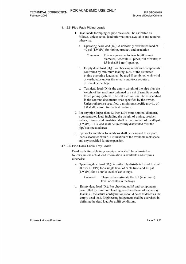
4.1.2.5 Pipe Rack Piping Loads
1. Dead loads for piping on pipe racks shall be estimated as
follows, unless actual load information is available and requires
otherwise:
a. Operating dead load (Do): A uniformly distributed load of40 psf (1.9 kPa) for piping, product, and insulation
Comment: This is equivalent to 8-inch (203-mm)
diameter, Schedule 40 pipes, full of water, at
15-inch (381-mm) spacing.
b. Empty dead load (De): For checking uplift and components
controlled by minimum loading, 60% of the estimated
piping operating loads shall be used if combined with wind
or earthquake unless the actual conditions require a
different percentage.
c. Test dead load (Dt) is the empty weight of the pipe plus theweight of test medium contained in a set of simultaneously
tested piping systems. The test medium shall be as specified
in the contract documents or as specified by the owner.
Unless otherwise specified, a minimum specific gravity of
1.0 shall be used for the test medium.
2. For any pipe larger than 12-inch (304-mm) nominal diameter,
a concentrated load, including the weight of piping, product,
valves, fittings, and insulation shall be used in lieu of the 40 psf
(1.9 kPa). This load shall be uniformly distributed over the
pipe’s associated area.
3. Pipe racks and their foundations shall be designed to supportloads associated with full utilization of the available rack space
and any specified future expansion.
4.1.2.6 Pipe Rack Cable Tray Loads
Dead loads for cable trays on pipe racks shall be estimated as
follows, unless actual load information is available and requires
otherwise:
a. Operating dead load (Do): A uniformly distributed dead load of
20 psf (1.0 kPa) for a single level of cable trays and 40 psf
(1.9 kPa) for a double level of cable trays.
Comment: These values estimate the full (maximum)
level of cables in the trays.
b. Empty dead load (De): For checking uplift and components
controlled by minimum loading, a reduced level of cable tray
load (i.e., the actual configuration) should be considered as the
empty dead load. Engineering judgement shall be exercised in
defining the dead load for uplift conditions.
FOR ACADEMIC USE ONLY

7/18/2019 XPIP STC01015 Str'l Design Criteria
http://slidepdf.com/reader/full/xpip-stc01015-strl-design-criteria 10/32
PIP STC01015 TECHNICAL CORRECTIONStructural Design Criteria February 2006
Page 8 of 30 Process Industry Practices
4.1.2.7 Ground-Supported Storage Tank Loads
Dead loads for ground-supported storage tanks are shown in Table 9
with the same nomenclature as other dead loads in this Practice for
consistency. The individual load components making up the dead
loads may have to be separated for actual use in design, discussed asfollows:
a. Operating dead load (Do): Operating dead load for a ground-
supported storage tank is made up of the metal load from the
tank shell and roof, vertically applied through the wall of the
tank, in addition to the fluid load from the stored product. The
fluid load acts through the bottom of the tank and does not act
vertically through the wall of the tank. Therefore, the metal
dead load and the fluid load must be used separately in design.
b. Empty dead load (De): For checking uplift and components
controlled by minimum loading, the corroded metal weight (if a
corrosion allowance is specified) should be considered as theempty dead load.
c. Test dead load (Dt): Test dead load for a ground-supported
storage tank is made up of the metal load from the tank shell
and roof, vertically applied through the wall of the tank, in
addition to the fluid load from the test medium. The fluid load
acts through the bottom of the tank and does not act vertically
through the wall of the tank. Therefore, the metal dead load and
the fluid load must be used separately in design. The test
medium shall be as specified in the contract documents or as
specified by the owner. Unless otherwise specified, a minimum
specific gravity of 1.0 shall be used for the test medium.
4.1.3 Live Loads (L)
4.1.3.1 Live loads are gravity loads produced by the use and occupancy of
the building or structure. These include the weight of all movable
loads, such as personnel, tools, miscellaneous equipment, movable
partitions, wheel loads, parts of dismantled equipment, stored
material, etc.
4.1.3.2 Areas specified for maintenance (e.g., heat exchanger tube bundle
servicing) shall be designed to support the live loads.
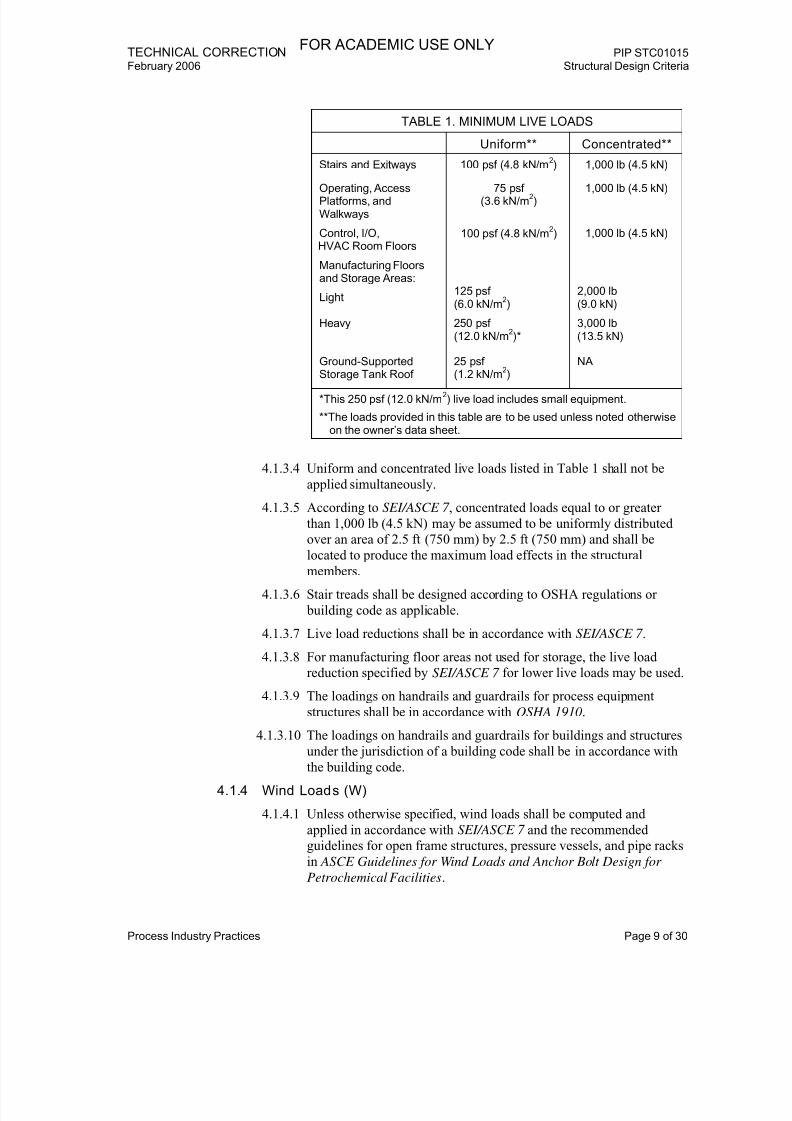
4.1.3.3 Minimum live loads shall be in accordance with SEI/ASCE 7 ,
applicable codes and standards, and, unless otherwise specified, in
Table 1:
FOR ACADEMIC USE ONLY
7/18/2019 XPIP STC01015 Str'l Design Criteria
http://slidepdf.com/reader/full/xpip-stc01015-strl-design-criteria 11/32
TECHNICAL CORRECTION PIP STC01015 February 2006 Structural Design Criteria
Process Industry Practices Page 9 of 30
TABLE 1. MINIMUM LIVE LOADS
Uniform** Concentrated**
Stairs and Exitways 100 psf (4.8 kN/m2) 1,000 lb (4.5 kN)
Operating, AccessPlatforms, andWalkways
75 psf(3.6 kN/m
2)
1,000 lb (4.5 kN)
Control, I/O,HVAC Room Floors
100 psf (4.8 kN/m2) 1,000 lb (4.5 kN)
Manufacturing Floorsand Storage Areas:
Light125 psf(6.0 kN/m
2)
2,000 lb(9.0 kN)
Heavy 250 psf(12.0 kN/m
2)*
3,000 lb(13.5 kN)
Ground-SupportedStorage Tank Roof
25 psf(1.2 kN/m
2)
NA
*This 250 psf (12.0 kN/m2) live load includes small equipment.
**The loads provided in this table are to be used unless noted otherwiseon the owner’s data sheet.
4.1.3.4 Uniform and concentrated live loads listed in Table 1 shall not be
applied simultaneously.
4.1.3.5 According to SEI/ASCE 7 , concentrated loads equal to or greater
than 1,000 lb (4.5 kN) may be assumed to be uniformly distributed
over an area of 2.5 ft (750 mm) by 2.5 ft (750 mm) and shall be
located to produce the maximum load effects in the structural
members.
4.1.3.6 Stair treads shall be designed according to OSHA regulations or
building code as applicable.
4.1.3.7 Live load reductions shall be in accordance with SEI/ASCE 7 .
4.1.3.8 For manufacturing floor areas not used for storage, the live load
reduction specified by SEI/ASCE 7 for lower live loads may be used.
4.1.3.9 The loadings on handrails and guardrails for process equipment
structures shall be in accordance with OSHA 1910.
4.1.3.10 The loadings on handrails and guardrails for buildings and structures
under the jurisdiction of a building code shall be in accordance with
the building code.
4.1.4 Wind Loads (W)
4.1.4.1 Unless otherwise specified, wind loads shall be computed and
applied in accordance with SEI/ASCE 7 and the recommended
guidelines for open frame structures, pressure vessels, and pipe racks
in ASCE Guidelines for Wind Loads and Anchor Bolt Design for
Petrochemical Facilities.
FOR ACADEMIC USE ONLY

7/18/2019 XPIP STC01015 Str'l Design Criteria
http://slidepdf.com/reader/full/xpip-stc01015-strl-design-criteria 12/32
PIP STC01015 TECHNICAL CORRECTIONStructural Design Criteria February 2006
Page 10 of 30 Process Industry Practices
4.1.4.2 Site specific design parameters shall be in accordance with
PIP CVC01017 .
4.1.4.3 The owner shall be consulted for the determination of the
classification category.
Comment: For process industry facilities, SEI/ASCE 7
Category III is the most likely classification because
of the presence of hazardous materials. Category II
may be used if the owner can demonstrate that
release of the hazardous material does not pose a
threat to the public. See SEI/ASCE 7-02,
Section 1.5.2 and Table 1-1, for specific details. In
some cases, it may be appropriate to select
Category IV.
4.1.4.4 The full design wind load shall be used when calculating wind drift
(see Section 4.3.6).
4.1.4.5 A solid width of 1.5 ft (450 mm) shall be assumed when calculatingthe wind load on ladder cages.
4.1.4.6 Partial wind load (WP) shall be based on the requirements of
SEI/ASCE 37-02, Section 6.2.1, for the specified test or erection
duration. The design wind speed shall be 68 mph (109 kph) (which is
0.75 x 90 mph [145 kph] according to SEI/ASCE 37 for test or
erection periods of less than 6 weeks).
4.1.4.7 For test or erection periods of 6 weeks or more or if the test or
erection is in a hurricane-prone area and is planned during the peak
hurricane season (from August 1 to October 31 in the U.S.A), see
SEI/ASCE 37-02, Section 6.2.1.
4.1.5 Earthquake Loads (E)
4.1.5.1 Except for API Standard 650 ground-supported storage tanks,
earthquake loads shall be computed and applied in accordance with
SEI/ASCE 7 , unless otherwise specified.
Comment: The earthquake loads in SEI/ASCE 7 are limit state
earthquake loads, and this should be taken into
account if using allowable stress design methods or
applying load factors from other codes. Earthquake
loads for API Standard 650 storage tanks are
allowable stress design loads.
4.1.5.2 Site specific design parameters shall conform to PIP CVC01017 .
4.1.5.3 ASCE Guidelines for Seismic Evaluation and Design of
Petrochemical Facilities may also be used as a general reference for
earthquake design.
Comment: Buildings and building-like structures, designed for
earthquakes according to SEI/ASCE 7 , are typically
classified as Category III. In some cases, it may be
appropriate to select Category IV.
FOR ACADEMIC USE ONLY

7/18/2019 XPIP STC01015 Str'l Design Criteria
http://slidepdf.com/reader/full/xpip-stc01015-strl-design-criteria 13/32
TECHNICAL CORRECTION PIP STC01015 February 2006 Structural Design Criteria
Process Industry Practices Page 11 of 30
4.1.5.4 Earthquake loading shall be determined using SEI/ASCE 7-02,
Section 9.14, if SEI/ASCE 7 is used for the earthquake design of
nonbuilding structures as defined in SEI/ASCE 7-02, Section 9.14.1.1
and Table 9.14.5.1.1.
Comment: Nonbuilding structures include but are not limited toelevated tanks or vessels, stacks, pipe racks, and
cooling towers.
4.1.5.5 The importance factor “I” for nonbuilding structures shall be
determined from SEI/ASCE 7-02, Table 9.14.5.1.2.
Comment: In general, for nonbuilding structures in
petrochemical process units, select seismic use group
II, giving an importance factor “I” of 1.25; however,
in some cases, it may be appropriate to select
seismic use group I or III.
4.1.5.6 For the load combinations in Section 4.2, the following designations
are used:
Eo = Earthquake load considering the unfactored operating dead
load and the applicable portion of the unfactored structure
dead load
Ee = Earthquake load considering the unfactored empty dead load
and the applicable portion of the unfactored structure dead
load
4.1.6 Impact Loads
4.1.6.1 Impact loads shall be in accordance with SEI/ASCE 7 .
4.1.6.2 Impact loads for davits shall be the same as those for monorail cranes(powered).
4.1.6.3 Lifting lugs or pad eyes and internal members (included both end
connections) framing into the joint where the lifting lug or pad eye is
located shall be designed for 100% impact.
4.1.6.4 All other structural members transmitting lifting forces shall be
designed for 15% impact.
4.1.6.5 Allowable stresses shall not be increased when combining impact
with dead load.
4.1.7 Thermal Loads
4.1.7.1 For this Practice, thermal loads are designated by the followingnomenclature:
T p, T, Af , and Ff , where
T p = Forces on vertical vessels, horizontal vessels, or heat
exchangers caused by the thermal expansion of the pipe
attached to the vessel
FOR ACADEMIC USE ONLY

7/18/2019 XPIP STC01015 Str'l Design Criteria
http://slidepdf.com/reader/full/xpip-stc01015-strl-design-criteria 14/32
PIP STC01015 TECHNICAL CORRECTIONStructural Design Criteria February 2006
Page 12 of 30 Process Industry Practices
T = Self-straining thermal forces caused by the restrained
expansion of horizontal vessels, heat exchangers, and
structural members in pipe racks or in structures
Af = Pipe anchor and guide forces
Ff = Pipe rack friction forces caused by the sliding of pipes or
friction forces caused by the sliding of horizontal vessels or
heat exchangers on their supports, in response to thermal
expansion
4.1.7.2 All support structures and elements thereof shall be designed to
accommodate the loads or effects produced by thermal expansion
and contraction of equipment and piping.
4.1.7.3 Thermal loads shall be included with operating loads in the
appropriate load combinations. Thermal load shall have the same
load factor as dead load.
4.1.7.4 Thermal loads and displacements shall be calculated on the basis ofthe difference between ambient or equipment design temperature and
installed temperature. To account for the significant increase in
temperatures of steel exposed to sunlight, 35oF (20oC) shall be added
to the maximum ambient temperature.
4.1.7.5 Friction loads caused by thermal expansion shall be determined
using the appropriate static coefficient of friction. Coefficients of
friction shall be in accordance with Table 2:
TABLE 2. COEFFICIENTS OF FRICTION
Steel to Steel 0.4
Steel to Concrete 0.6
Proprietary Sliding Surfaces orCoatings (e.g., “Teflon”)
According to Manufacturer’sInstructions
4.1.7.6 Friction loads shall be considered temporary and shall not be
combined with wind or earthquake loads. However, anchor and
guide loads (excluding their friction component) shall be combined
with wind or earthquake loads.
4.1.7.7 For pipe racks supporting multiple pipes, 10% of the total piping
weight shall be used as an estimated horizontal friction load applied
only to local supporting beams. However, an estimated friction load
equal to 5% of the total piping weight shall be accumulated and
carried into pipe rack struts, columns, braced anchor frames, and
foundations.
Comment: Under normal loading conditions with multiple
pipes, torsional effects on the local beam need not be
considered because the pipes supported by the beam
limit the rotation of the beam to the extent that the
torsional stresses are minimal. Under certain
FOR ACADEMIC USE ONLY

7/18/2019 XPIP STC01015 Str'l Design Criteria
http://slidepdf.com/reader/full/xpip-stc01015-strl-design-criteria 15/32
TECHNICAL CORRECTION PIP STC01015 February 2006 Structural Design Criteria
Process Industry Practices Page 13 of 30
circumstances, engineering judgement shall be
applied to determine whether a higher friction load
and/or torsional effects should be used.
4.1.7.8 Pipe anchor and guide loads shall have the same load factor as dead
loads.
4.1.7.9 Internal pressure and surge shall be considered for pipe anchor and
guide loads.
4.1.7.10 Beams, struts, columns, braced anchor frames, and foundations shall
be designed to resist actual pipe anchor and guide loads.
4.1.7.11 For local beam design, only the top flange shall be considered
effective for horizontal bending unless the pipe anchor engages both
flanges of the beam.
4.1.8 Bundle Pull Load (Bp)
4.1.8.1 Structures and foundations supporting heat exchangers subject to
bundle pulling shall be designed for a horizontal load equal to1.0 times the weight of the removable tube bundle but not less than
2,000 lb (9.0 kN). If the total weight of the exchanger is less than
2,000 lb (9.0 kN), the bundle pull design load need not exceed the
total weight of the exchanger.
4.1.8.2 Bundle pull load shall be applied at the center of the bundle.
Comment: If it can be assured that the bundles will be removed
strictly by the use of a bundle extractor attaching
directly to the exchanger (such that the bundle pull
force is not transferred to the structure or
foundation), the structure or foundation need not be
designed for the bundle pull force. Such assurancewould typically require the addition of a sign posted
on the exchanger to indicate bundle removal by an
extractor only.
4.1.8.3 The portion of the bundle pull load at the sliding end support shall
equal the friction force or half the total bundle pull load, whichever
is less. The remainder of the bundle pull load shall be resisted at the
anchor end support.
4.1.9 Traffic Loads
4.1.9.1 Buildings, trenches, and underground installations accessible to truck
loading shall be designed to withstand HS20 load as defined by AASHTO Standard Specifications for Highway Bridges.
4.1.9.2 Maintenance or construction crane loads shall also be considered
where applicable.
4.1.9.3 Truck or crane loads shall have the same load factor as live load.
FOR ACADEMIC USE ONLY
7/18/2019 XPIP STC01015 Str'l Design Criteria
http://slidepdf.com/reader/full/xpip-stc01015-strl-design-criteria 16/32
PIP STC01015 TECHNICAL CORRECTIONStructural Design Criteria February 2006
Page 14 of 30 Process Industry Practices
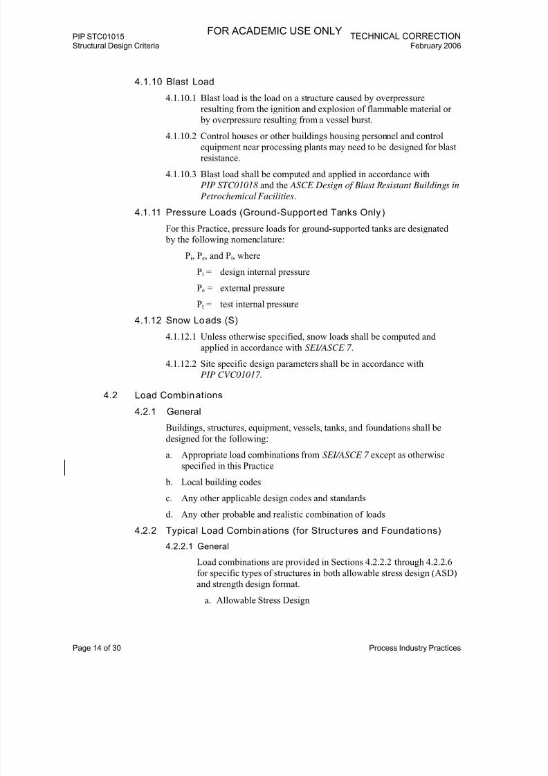
4.1.10 Blast Load
4.1.10.1 Blast load is the load on a structure caused by overpressure
resulting from the ignition and explosion of flammable material or
by overpressure resulting from a vessel burst.
4.1.10.2 Control houses or other buildings housing personnel and control
equipment near processing plants may need to be designed for blast
resistance.
4.1.10.3 Blast load shall be computed and applied in accordance with
PIP STC01018 and the ASCE Design of Blast Resistant Buildings in
Petrochemical Facilities.
4.1.11 Pressure Loads (Ground-Supported Tanks Only)
For this Practice, pressure loads for ground-supported tanks are designated
by the following nomenclature:
Pi, Pe, and Pt, where
Pi = design internal pressure
Pe = external pressure
Pt = test internal pressure
4.1.12 Snow Loads (S)
4.1.12.1 Unless otherwise specified, snow loads shall be computed and
applied in accordance with SEI/ASCE 7 .
4.1.12.2 Site specific design parameters shall be in accordance with
PIP CVC01017.
4.2 Load Combinations
4.2.1 General
Buildings, structures, equipment, vessels, tanks, and foundations shall be
designed for the following:
a. Appropriate load combinations from SEI/ASCE 7 except as otherwise
specified in this Practice
b. Local building codes
c. Any other applicable design codes and standards
d. Any other probable and realistic combination of loads
4.2.2 Typical Load Combinations (for Structures and Foundations)
4.2.2.1 General
Load combinations are provided in Sections 4.2.2.2 through 4.2.2.6
for specific types of structures in both allowable stress design (ASD)
and strength design format.
a. Allowable Stress Design
FOR ACADEMIC USE ONLY

7/18/2019 XPIP STC01015 Str'l Design Criteria
http://slidepdf.com/reader/full/xpip-stc01015-strl-design-criteria 17/32
TECHNICAL CORRECTION PIP STC01015 February 2006 Structural Design Criteria
Process Industry Practices Page 15 of 30
1. The noncomprehensive list of typical load combinations for
each type of structure provided in Sections 4.2.2.2
through 4.2.2.6 shall be considered and used as applicable.
2. Engineering judgment shall be used in establishing all
appropriate load combinations.
3. The use of a one-third stress increase for load combinations
including wind or earthquake loads shall not be allowed for
designs using the AISC ASD.
4. Steel structures in Seismic Design Category D or higher
shall use factored load combinations as specified in
ANSI/AISC 341-02, Part III (Allowable Stress Design
Alternative).
Comment: The dead load factor used for the seismic uplift
ASD load combinations is generally taken
as 0.9. This factor is greater than the 0.6 dead
load factor used in the ASD load combinationsof SEI/ASCE 7-02, Section 2, because the dead
loads of nonbuilding structures are known to a
higher degree of accuracy than are the
corresponding dead loads of buildings. A dead
load factor of 0.9 instead of 1.0 is used to
account for the effect of vertical seismic forces.
The use of this reduction is necessary because
foundations sized using ASD loads, except for
foundations for ground-supported storage tanks,
are generally not required to consider the effect
of vertical seismic uplift forces if a dead load
factor of 0.6 is used. A dead load factor of 1.0 isused for the wind uplift ASD load combinations
because of the higher accuracy of dead loads of
nonbuilding structures.
b. Strength Design
1. The noncomprehensive list of typical factored load
combinations for each type of structure provided in
Sections 4.2.2.2 through 4.2.2.6 shall be considered and
used as applicable.
2. Engineering judgment shall be used in establishing all
appropriate load combinations.3. The following load combinations are appropriate for use
with the strength design provisions of either AISC LRFD
(third edition or later) or ACI 318 (2002 edition or later).
4.2.2.2 General Plant Struc tures
Load combinations for buildings and open frame structures shall be
in accordance with SEI/ASCE 7-02, Section 2.
FOR ACADEMIC USE ONLY

7/18/2019 XPIP STC01015 Str'l Design Criteria
http://slidepdf.com/reader/full/xpip-stc01015-strl-design-criteria 18/32
PIP STC01015 TECHNICAL CORRECTIONStructural Design Criteria February 2006
Page 16 of 30 Process Industry Practices
4.2.2.3 Vertical Vessels
TABLE 3. LOADING COMBINATIONS - ALLOWABLE STRESSDESIGN (SERVICE LOADS)
Load
Comb.No. Load Combination
Allowable
StressMultiplier Description
1 Ds + Do + L 1.00 Operating Weight +Live Load
2 Ds + Do +(W or 0.7 Eo
a)
1.00 Operating Weight +Wind or Earthquake
3 Ds + De + W 1.00 Empty Weight +Wind
(Wind Uplift Case)
4a 0.9 (Ds + Do) + 0.7 Eoa 1.00 Operating Weight +
Earthquake(Earthquake Uplift
Case)4b 0.9 (Ds + De) + 0.7 Ee
a 1.00 Empty Weight +
Earthquake(Earthquake Uplift
Case)
5 Ds + Df + Wp 1.00 Erection Weight +Partial Wind
b
(Wind Uplift Case)
6 Ds + Dt + Wp 1.20 Test Weight +Partial Wind
Notes:
a. For skirt-supported vertical vessels and skirt-supported elevated tanksclassified as SUG III in accordance with SEI/ASCE 7-02, Section 9,the critical earthquake provisions and implied load combination ofSEI/ASCE 7-02, Section 9.14.7.3.10.5, shall be followed.
b. Erection weight + partial wind is required only if the erection weight ofthe vessel is significantly less than the empty weight of the vessel.
c. Thrust forces caused by thermal expansion of piping shall be includedin the calculations for operating load combinations, if deemedadvisable. The pipe stress engineer shall be consulted for any thermalloads that are to be considered.
FOR ACADEMIC USE ONLY

7/18/2019 XPIP STC01015 Str'l Design Criteria
http://slidepdf.com/reader/full/xpip-stc01015-strl-design-criteria 19/32
TECHNICAL CORRECTION PIP STC01015 February 2006 Structural Design Criteria
Process Industry Practices Page 17 of 30
TABLE 4. LOADING COMBINATIONS AND LOAD FACTORS –STRENGTH DESIGN
Load
Comb.
No. Load Combination Description1 1.4 (Ds + Do) Operating Weight
2 1.2 (Ds + Do) + 1.6 L Operating Weight + Live Load
3 1.2 (Ds + Do) +(1.6 W or 1.0 Eo
a)
Operating Weight + Wind orEarthquake
4 0.9 (Ds + De) + 1.6 W Empty Weight + Wind(Wind Uplift Case)
5a 0.9 (Ds + Do) + 1.0 Eoa Operating Weight + Earthquake
(Earthquake Uplift Case)
5b 0.9 (Ds + De) + 1.0 Eea Empty Weight + Earthquake
(Earthquake Uplift Case)
6 0.9 (Ds + Df ) + 1.6 Wp Erection Weight + Partial Windb
(Wind Uplift Case)
7 1.4 (Ds + Dt) Test Weight
8 1.2 (Ds + Dt) + 1.6 Wp Test Weight + Partial Wind
Notes:
a. For skirt-supported vertical vessels and skirt-supported elevated tanksclassified as SUG III in accordance with SEI/ASCE 7-02, Section 9, thecritical earthquake provisions and implied load combination ofSEI/ASCE 7-02, Section 9.14.7.3.10.5, shall be followed.
b. Erection weight + partial wind is required only if the erection weight of
the vessel is significantly less than the empty weight of the vessel.
c. Thrust forces caused by thermal expansion of piping shall be includedin the calculations for operating load combinations, if deemedadvisable. The pipe stress engineer shall be consulted for any thermalloads that are to be considered. The same load factor as used for deadload shall be used.
FOR ACADEMIC USE ONLY

7/18/2019 XPIP STC01015 Str'l Design Criteria
http://slidepdf.com/reader/full/xpip-stc01015-strl-design-criteria 20/32
PIP STC01015 TECHNICAL CORRECTIONStructural Design Criteria February 2006
Page 18 of 30 Process Industry Practices
4.2.2.4 Horizontal Vessels and Heat Exchangers
TABLE 5. LOADING COMBINATIONS - ALLOWABLE STRESSDESIGN (SERVICE LOADS)
Load
Comb.No.
Load Combination
Allowable
StressMultiplier Description
1 Ds + Do +(T or Ff )
b1.00 Operating Weight +
Thermal Expansion orFriction Force
2 Ds + Do + L +(T or Ff )
b
1.00 Operating Weight +Live Load +
Thermal Expansion orFriction Force
3 Ds + Do +(W or 0.7 Eo)
1.00 Operating Weight +Wind or Earthquake
4 Ds + De + W 1.00 Empty Weight + Wind
(Wind Uplift Case)
5a 0.9 (Ds + Do) +0.7 Eo
1.00 Operating Weight +Earthquake
(Earthquake Uplift Case)
5b 0.9 (Ds + De) +0.7 Ee
1.00 Empty Weight +Earthquake
(Earthquake Uplift Case)
6 Ds + Df + Wp 1.00 Erection Weight +Partial Wind
c
(Wind Uplift Case)
7 Ds + Dt + Wp 1.20 Test Weight +Partial Wind
(For Horizontal VesselsOnly)
8 Ds + Ded+ Bp 1.00 Empty Weight +
Bundle Pull(For Heat Exchangers
Only)
Notes:
a. Wind and earthquake forces shall be applied in both transverse andlongitudinal directions, but shall not necessarily be appliedsimultaneously.
b. The design thermal force for horizontal vessels and heat exchangersshall be the lesser of T or F f .
c. Erection weight + partial wind is required only if the erection weight ofthe vessel or exchanger is significantly less than the empty weight ofthe vessel or exchanger.
d. Heat exchanger empty dead load will be reduced during bundle pullbecause of the removal of the exchanger head.
e. Sustained thermal loads not relieved by sliding caused by vessel orexchanger expansion shall be considered in operating loadcombinations with wind or earthquake.
FOR ACADEMIC USE ONLY

7/18/2019 XPIP STC01015 Str'l Design Criteria
http://slidepdf.com/reader/full/xpip-stc01015-strl-design-criteria 21/32
TECHNICAL CORRECTION PIP STC01015 February 2006 Structural Design Criteria
Process Industry Practices Page 19 of 30
f. Thrust forces caused by thermal expansion of piping shall be included in thecalculations for operating load combinations if deemed advisable. The pipestress engineer shall be consulted for any thermal loads that are to beconsidered.
TABLE 6. LOADING COMBINATIONS AND LOAD FACTORS –STRENGTH DESIGN
Load
Comb.No. Load Combination Description
1 1.4 (Ds + Do) + 1.4 (T or Ff )b Operating Weight +
Thermal Expansion or Friction Force
2 1.2 (Ds + Do) + 1.6 L +1.2 (T or Ff )
b
Operating Weight + Live Load +Thermal Expansion or Friction Force
3 1.2 (Ds + Do) +
(1.6 W or 1.0 Eo)
Operating Weight +
Wind or Earthquake
4 0.9 (Ds + De) + 1.6 W Empty Weight + Wind(Wind Uplift Case)
5a 0.9 (Ds + Do) + 1.0 Eo Operating Weight + Earthquake(Earthquake Uplift Case)
5b 0.9 (Ds + De) + 1.0 Ee Empty Weight + Earthquake(Earthquake Uplift Case)
6 0.9 (Ds + Df ) + 1.6 Wp Erection Weight + Partial Windc
(Wind Uplift Case)
7 1.4 (Ds + Dt) Test Weight(For Horizontal Vessels Only)
8 1.2 (Ds + Dt) + 1.6 Wp Test Weight + Partial Wind(For Horizontal Vessels Only)
9 1.2 (Ds + Ded) + 1.6 Bp Empty Weight + Bundle Pull
(For Heat Exchangers Only)
10 0.9 (Ds + Ded) + 1.6 Bp Empty Weight + Bundle Pull
(For Heat Exchangers Only)(Bundle Pull Uplift Case)
Notes:
a. Wind and earthquake forces shall be applied in both transverse and longitudinaldirections, but shall not necessarily be applied simultaneously.
b. The design thermal force for horizontal vessels and heat exchangers shall bethe lesser of T or Ff.
c. Erection weight + partial wind is required only if the erection weight of the vesselor exchanger is significantly less than the empty weight of the vessel orexchanger.
d. Heat exchanger empty dead load will be reduced during bundle pull because ofthe removal of the exchanger head.
FOR ACADEMIC USE ONLY

7/18/2019 XPIP STC01015 Str'l Design Criteria
http://slidepdf.com/reader/full/xpip-stc01015-strl-design-criteria 22/32
PIP STC01015 TECHNICAL CORRECTIONStructural Design Criteria February 2006
Page 20 of 30 Process Industry Practices
e. Sustained thermal loads not relieved by sliding from vessel orexchanger expansion shall be considered in operating loadcombinations with wind or earthquake.
f. Thrust forces caused by thermal expansion of piping shall be includedin the calculations for operating load combinations, if deemed
advisable. The pipe stress engineer shall be consulted for any thermalloads that are to be considered. The same load factor as used fordead load shall be used.
4.2.2.5 Pipe Rack and Pipe Bridge Design
TABLE 7. LOADING COMBINATIONS - ALLOWABLE STRESSDESIGN (SERVICE LOADS)
LoadComb.
No. Load Combination
Allow able
StressMultiplier Description
1 Ds + Do + Ff + T + Af 1.00 Operating Weight +Friction Force +
Thermal Expansion + Anchor Force
2 Ds + Do + Af +(W or 0.7 Eo)
1.00 Operating Weight + Anchor + Wind or
Earthquake
3 Ds + Dec + W 1.00 Empty Weight + Wind
(Wind Uplift Case)
4a 0.9 (Ds) + 0.6 (Do) + Af + 0.7 Eo
d1.00 Operating Weight +
Earthquake(Earthquake Uplift
Case)
4b 0.9 (Ds + De
c
) +0.7 Ee 1.00 Empty Weight +Earthquake
(Earthquake UpliftCase)
5 Ds + Dt + Wp 1.20 Test Weight +Partial Wind
e
Notes:
a. Considerations of wind forces are normally not necessary in thelongitudinal direction because friction and anchor loads will normallygovern.
b. Earthquake forces shall be applied in both transverse and longitudinaldirections, but shall not necessarily be applied simultaneously.
c. 0.6Do is used as a close approximation of the empty pipe condition De.
d. Full Ds + Do value shall be used for the calculation of Eo in loadcombination 4a.
e. Test weight + partial wind normally is required only for local memberdesign because test is not typically performed on all pipessimultaneously.
FOR ACADEMIC USE ONLY
7/18/2019 XPIP STC01015 Str'l Design Criteria
http://slidepdf.com/reader/full/xpip-stc01015-strl-design-criteria 23/32
TECHNICAL CORRECTION PIP STC01015 February 2006 Structural Design Criteria
Process Industry Practices Page 21 of 30
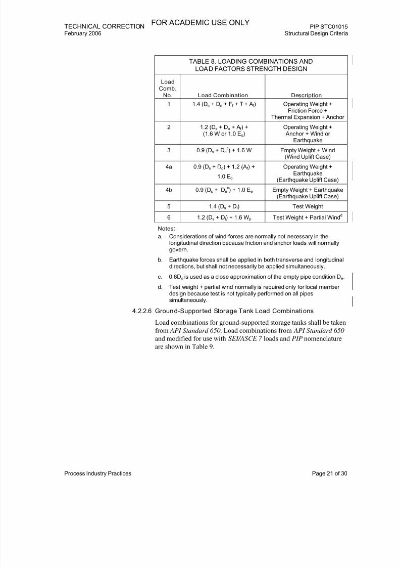
TABLE 8. LOADING COMBINATIONS ANDLOAD FACTORS STRENGTH DESIGN
Load
Comb.
No. Load Combination Description1 1.4 (Ds + Do + Ff + T
+ Af ) Operating Weight +
Friction Force +Thermal Expansion + Anchor
2 1.2 (Ds + Do + Af ) +(1.6 W or 1.0 Eo)
Operating Weight + Anchor + Wind or
Earthquake
3 0.9 (Ds + Dec) + 1.6 W Empty Weight + Wind
(Wind Uplift Case)
4a 0.9 (Ds + Do) + 1.2 (Af ) +
1.0 Eo
Operating Weight +Earthquake
(Earthquake Uplift Case)
4b 0.9 (Ds + De
c
) + 1.0 Ee Empty Weight + Earthquake(Earthquake Uplift Case)
5 1.4 (Ds + Dt) Test Weight
6 1.2 (Ds + Dt) + 1.6 Wp Test Weight + Partial Windd
Notes:
a. Considerations of wind forces are normally not necessary in thelongitudinal direction because friction and anchor loads will normallygovern.
b. Earthquake forces shall be applied in both transverse and longitudinaldirections, but shall not necessarily be applied simultaneously.
c. 0.6Do is used as a close approximation of the empty pipe condition De.
d. Test weight + partial wind normally is required only for local memberdesign because test is not typically performed on all pipessimultaneously.
4.2.2.6 Ground-Suppor ted Storage Tank Load Combinations
Load combinations for ground-supported storage tanks shall be taken
from API Standard 650. Load combinations from API Standard 650
and modified for use with SEI/ASCE 7 loads and PIP nomenclature
are shown in Table 9.
FOR ACADEMIC USE ONLY

7/18/2019 XPIP STC01015 Str'l Design Criteria
http://slidepdf.com/reader/full/xpip-stc01015-strl-design-criteria 24/32
PIP STC01015 TECHNICAL CORRECTIONStructural Design Criteria February 2006
Page 22 of 30 Process Industry Practices
TABLE 9. LOADING COMBINATIONS - ALLOWABLE STRESSDESIGN (SERVICE LOADS)
Load
Comb.
No. Load Combination Description1 Ds + Do + Pi Operating Weight +
Internal Pressurea
2 Ds + Dt + Pt Test Weight +Test Pressure
3 Ds + (De or Do) + W + 0.4 Pib Empty or Operating
Weight + Wind +Internal Pressure
a
4 Ds + (De or Do) + W + 0.4 Peb
Empty or OperatingWeight + Wind +External Pressure
5 Ds + Do + (L or S) + 0.4 Peb
Operating Weight +Live or Snow +
External Pressure
6 Ds + (De or Do) + 0.4 (L or S) + Pe Empty or OperatingWeight +
Live or Snow +External Pressure
7 Ds + Do + 0.1 S + Eoc + 0.4 Pi
bOperating Weight +
Snow + Earthquake +Internal Pressure
a
(Earthquake UpliftCase)
8 Ds + Do + 0.1 S + Eoc
Operating Weight +Snow + Earthquake
Notes:a. For internal pressures sufficient to lift the tank shell according to the
rules of API Standard 650, tank, anchor bolts, and foundation shall bedesigned to the additional requirements of API Standard 650
Appendix F.7.
b. If the ratio of operating pressure to design pressure exceeds 0.4, theowner shall consider specifying a higher factor on design pressure inload combinations 3, 4, 5, and 7 of Table 9.
c. Earthquake loads for API Standard 650 tanks taken from SEI/ASCE 7 “bridging equations” or from API Standard 650 already include the0.7 ASD seismic load factor.
4.2.2.7 Load Combinations for Static Machinery, Skid and Modular
Equipment, Filters, and Other Equipment
Load combinations for static machinery, skid and modular
equipment, filters, etc., shall be similar to the load combinations for
vertical vessels.
4.2.3 Test Combinations
4.2.3.1 Engineering judgment shall be used in establishing the appropriate
application of test load combinations to adequately address actual
FOR ACADEMIC USE ONLY

7/18/2019 XPIP STC01015 Str'l Design Criteria
http://slidepdf.com/reader/full/xpip-stc01015-strl-design-criteria 25/32
TECHNICAL CORRECTION PIP STC01015 February 2006 Structural Design Criteria
Process Industry Practices Page 23 of 30
test conditions in accordance with project and code requirements
while avoiding overly conservative design.
4.2.3.2 Consideration shall be given to the sequence and combination of
testing for various equipment, vessels, tanks. and/or piping systems
supported on common structures, pipe racks, or foundations.
4.2.3.3 Full wind and earthquake loads are typically not combined with test
loads unless an unusually long test duration is planned (i.e., if a
significant probability exists that the “partial wind velocity” will be
exceeded or an earthquake event may occur).
4.2.3.4 Additional loading shall be included with test if specified in the
contract documents.
4.2.3.5 For allowable stress design, a 20% allowable stress increase shall be
permitted for any test load combination.
4.2.3.6 For ultimate strength/limit states design, no load factor reduction
shall be permitted for any test load combination.
4.3 Structural Design
4.3.1 Steel
4.3.1.1 Steel design shall be in accordance with AISC ASD or AISC LRFD
specifications.
4.3.1.2 For cold-formed shapes, design shall be in accordance with AISI
specifications.
4.3.1.3 Steel joists shall be designed in accordance with SJI standards.
Comment: Supplement number 1 to the AISC ASD
specification deleted the one-third stress increasefor use with load combinations including wind or
earthquake loads. Because of the deletion of the
one-third stress increase, designs made to the AISC
LRFD specifications should be considered for
economy.
4.3.1.4 Steel design, including steel joists and metal decking, shall be
designed in accordance with OSHA 29 CFR 1926 , Subpart R, to
provide structural stability during erection and to protect employees
from the hazards associated with steel erection activities.
Comment: Common requirements that affect steel design areas
follow (this is not an all inclusive list):
a. All column base plates shall be designed with a minimum of
four anchor bolts. Posts (which weigh less than 300 lb [136 kg])
are distinguished from columns and are excluded from the four-
anchor bolt requirement.
b. Columns, column base plates, and their foundations shall be
designed to resist a minimum eccentric gravity load of 300 lb
(136 kg) located 18 inches (450 mm) from the extreme outer
FOR ACADEMIC USE ONLY
7/18/2019 XPIP STC01015 Str'l Design Criteria
http://slidepdf.com/reader/full/xpip-stc01015-strl-design-criteria 26/32
PIP STC01015 TECHNICAL CORRECTIONStructural Design Criteria February 2006
Page 24 of 30 Process Industry Practices
face of the column in each direction at the top of the column
shaft. Column splices shall be designed to meet the same load-
resisting characteristics as those of the columns.
c. Double connections through column webs or at beams that
frame over the tops of columns shall be designed so that at leastone installed bolt remains in place to support the first beam
while the second beam is being erected. The fabricator may also
supply a seat or equivalent device with a means of positive
attachment to support the first beam while the second beam is
being erected.
d. Perimeter columns shall extend 48 inches (1,200 mm) above the
finished floor (unless constructability does not allow) to allow
the installation of perimeter safety cables. Provision shall be
made for the attachment of safety cables.
e. Structural members of framed metal deck openings shall be
turned down to allow continuous decking, except where notallowed by design constraints or constructability. The openings
in the metal deck shall not be cut until the hole is needed.
f. Shear stud connectors that will project vertically from or
horizontally across the top flange of the member shall not be
attached to the top flanges of beams, joists, or beam attachments
until after the metal decking or other walking/working surface
has been installed.
4.3.1.5 All welded structural connections shall use weld filler material
conforming to AWS D1.1/D1.1M , Section 3.3 (including Table 3.1),
and have an electrode strength of 58 ksi (400 MPa) minimum yield
strength and 70 ksi (480 MPa) tensile strength, unless otherwiserequired.
4.3.1.6 Structural steel wide-flange shapes, including WT shapes, shall be in
accordance with ASTM A992/A992M , unless otherwise specified.
4.3.1.7 All other structural shapes, plates, and bars shall be in accordance
with ASTM A36/A36M , unless otherwise specified.
4.3.1.8 Preference in design shall be given to shop-welded, field-bolted
connections.
4.3.1.9 Compression flanges of floor beams, not supporting equipment, may
be considered braced by decking (concrete or floor plate) if
positively connected thereto.4.3.1.10 Grating shall not be considered as lateral bracing for support beams.
4.3.1.11 Except as specified in Section 4.3.1.12 or if slip-critical connections
are required by the AISC Specification for Structural Joints Using
ASTM A325 or A490 Bolts, all bolts 3/4 inches (19 mm) and larger
(except anchor bolts) shall be type-N (bearing-type with threads
included in the shear plane) high-strength ASTM A325 bolts.
4.3.1.12 Bolt size shall be as follows:
FOR ACADEMIC USE ONLY
7/18/2019 XPIP STC01015 Str'l Design Criteria
http://slidepdf.com/reader/full/xpip-stc01015-strl-design-criteria 27/32
TECHNICAL CORRECTION PIP STC01015 February 2006 Structural Design Criteria
Process Industry Practices Page 25 of 30
a. Structural members - 3/4 inch (19 mm) minimum
b. Railings, ladders, purlins, and girts - 5/8 inch, (16 mm)
ASTM A307
4.3.1.13 Minimum thickness of bracing gusset plates shall be 3/8 inch
(10 mm).
4.3.2 Concrete
4.3.2.1 Concrete design shall be in accordance with ACI 318/318R.
4.3.2.2 Concrete design for liquid-containing structures shall also be
designed in accordance with ACI 350R.
4.3.2.3 Unless otherwise specified, all reinforcing steel shall be in
accordance with ASTM A615/A615M Grade 60 deformed.
4.3.2.4 ASTM A615/A615M Grade 60 plain wire conforming to
ASTM A82/A82M may be used for spiral reinforcement.
4.3.2.5 Welded wire fabric shall conform to ASTM A185/A185M .
4.3.2.6 Reinforcement designed to resist earthquake-induced flexural and
axial forces in frame members and in wall boundary elements shall
be in accordance with ASTM A706/A706M . ASTM A615/A615M
Grade 60 reinforcement is acceptable for these members under the
following conditions:
a. The actual yield strength based on mill tests does not exceed the
specified yield strength by more than 18,000 psi (124 MPa).
Retests shall not exceed this value by more than an additional
3,000 psi (20.7 MPa).
b. The ratio of the actual ultimate tensile strength to the actualtensile yield strength is not less than 1.25.
4.3.2.7 Precast and prestressed concrete shall be in accordance with the
PCI Design Handbook.
4.3.3 Masonry
Masonry design shall be in accordance with ACI 530/ASCE 5.
4.3.4 Elevator Supports
Elevator support design shall be in accordance with ASME A17.1.
4.3.5 Crane Supports
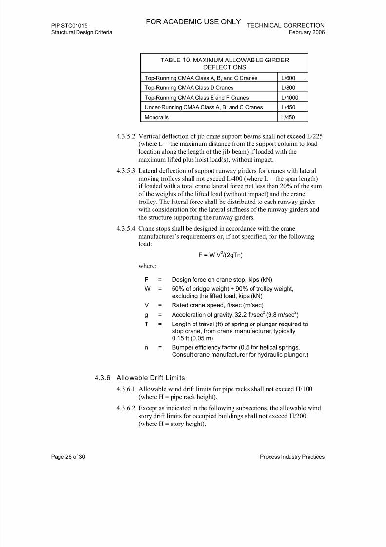
4.3.5.1 Vertical deflection of support runway girders shall not exceed thefollowing limits given in Table 10 if loaded with the maximum
wheel load(s), without impact (where L = the span length).
FOR ACADEMIC USE ONLY
7/18/2019 XPIP STC01015 Str'l Design Criteria
http://slidepdf.com/reader/full/xpip-stc01015-strl-design-criteria 28/32
PIP STC01015 TECHNICAL CORRECTIONStructural Design Criteria February 2006
Page 26 of 30 Process Industry Practices
TABLE 10. MAXIMUM ALLOWABLE GIRDER
DEFLECTIONS
Top-Running CMAA Class A, B, and C Cranes L/600
Top-Running CMAA Class D Cranes L/800
Top-Running CMAA Class E and F Cranes L/1000
Under-Running CMAA Class A, B, and C Cranes L/450
Monorails L/450
4.3.5.2 Vertical deflection of jib crane support beams shall not exceed L/225
(where L = the maximum distance from the support column to load
location along the length of the jib beam) if loaded with the
maximum lifted plus hoist load(s), without impact.
4.3.5.3 Lateral deflection of support runway girders for cranes with lateral
moving trolleys shall not exceed L/400 (where L = the span length)
if loaded with a total crane lateral force not less than 20% of the sumof the weights of the lifted load (without impact) and the crane
trolley. The lateral force shall be distributed to each runway girder
with consideration for the lateral stiffness of the runway girders and
the structure supporting the runway girders.
4.3.5.4 Crane stops shall be designed in accordance with the crane
manufacturer’s requirements or, if not specified, for the following
load:
F = W V2/(2gTn)
where:
F = Design force on crane stop, kips (kN)
W = 50% of bridge weight + 90% of trolley weight,excluding the lifted load, kips (kN)
V = Rated crane speed, ft/sec (m/sec)
g = Acceleration of gravity, 32.2 ft/sec2(9.8 m/sec
2)
T = Length of travel (ft) of spring or plunger required tostop crane, from crane manufacturer, typically0.15 ft (0.05 m)
n = Bumper efficiency factor (0.5 for helical springs.Consult crane manufacturer for hydraulic plunger.)
4.3.6 Allowable Drift Limi ts
4.3.6.1 Allowable wind drift limits for pipe racks shall not exceed H/100
(where H = pipe rack height).
4.3.6.2 Except as indicated in the following subsections, the allowable wind
story drift limits for occupied buildings shall not exceed H/200
(where H = story height).
FOR ACADEMIC USE ONLY
7/18/2019 XPIP STC01015 Str'l Design Criteria
http://slidepdf.com/reader/full/xpip-stc01015-strl-design-criteria 29/32
TECHNICAL CORRECTION PIP STC01015 February 2006 Structural Design Criteria
Process Industry Practices Page 27 of 30
4.3.6.3 Allowable wind drift limits for pre-engineered metal buildings shall
not exceed H/80 (where H = building height).
4.3.6.4 Allowable wind drift limits for a building with a bridge crane that is
required to be in service even during hurricanes shall not exceed
H/400 or 2 inches (50 mm), whichever is less (where H = the heightfrom the base of the crane support structure to the top of the runway
girder).
4.3.6.5 Allowable wind drift limits for buildings with bridge cranes that will
not be in service during hurricanes shall not exceed H/140 or
2 inches (50 mm), whichever is less (see Section 4.3.6.4 for
definition of H).
4.3.6.6 Allowable wind drift limits for process structures and personnel
access platforms shall not exceed H/200 (where H = structure height
at elevation of drift consideration).
4.3.6.7 Allowable seismic drift limits shall be in accordance with
SEI/ASCE 7 .
4.3.7 Foundations
4.3.7.1 Foundation design shall be based on the results of a geotechnical
engineering investigation.
4.3.7.2 The minimum overturning “stability ratio” for service loads other
than earthquake shall be 1.5 (see Section 4.3.7.4 for the minimum
overturning “stability ratio” for earthquake loads). For foundation
design of buildings and open frame structures, if the dead load factor
is 0.6 in accordance with SEI/ASCE 7-02, Section 2, the minimum
overturning “stability ratio” shall be 1.0.
Comment: This requirement is consistent with SEI/ASCE 7 provisions, in which the “factor of safety” is built
into the 0.6 “dead load factor” in the load
combinations.
4.3.7.3 The minimum factor of safety against sliding for service loads other
than earthquake shall be 1.5 (see Section 4.3.7.4 for the minimum
sliding factor of safety for earthquake loads). For foundation design
of buildings and open frame structures, if the dead load factor is 0.6
in accordance with SEI/ASCE 7-02, Section 2, the minimum factor of
safety against sliding shall be 1.0.
Comment : This requirement is consistent with SEI/ASCE 7
provisions, in which the “factor of safety” is builtinto the 0.6 “dead load factor” in the load
combinations.
4.3.7.4 Overturning and sliding caused by earthquake loads shall be checked
in accordance with SEI/ASCE 7-02, Section 9. The minimum
overturning “stability ratio” and the minimum factor of safety against
sliding for earthquake service loads shall be 1.0. In addition, the
minimum overturning “stability ratio” for the anchorage and
FOR ACADEMIC USE ONLY

7/18/2019 XPIP STC01015 Str'l Design Criteria
http://slidepdf.com/reader/full/xpip-stc01015-strl-design-criteria 30/32
PIP STC01015 TECHNICAL CORRECTIONStructural Design Criteria February 2006
Page 28 of 30 Process Industry Practices
foundations of skirt-supported vertical vessels and skirt-supported
elevated tanks classified as SUG III in accordance with
SEI/ASCE 7-02, Section 9, shall be 1.2 for the critical earthquake
loads specified in SEI/ASCE 7-02, Section 9.14.7.3.10.5.
4.3.7.5 For earthquake loads calculated by the “Equivalent Lateral ForceProcedure” in SEI/ASCE 7 , additional stability checks shall be done
in accordance with SEI/ASCE 7-02, Section 9, Section 9.5.5.6,
“Overturning.” For foundations designed using seismic load
combination from Tables 3, 5, and 7 of this Practice, the reduction in
the foundation overturning moment permitted in SEI/ASCE 7-02,
Section 9, Section 9.5.5.6, “Overturning,” shall not be used.
4.3.7.6 The minimum factor of safety against buoyancy shall be 1.2 if using
actual unfactored service loads.
4.3.7.7 Long-term and differential settlement shall be considered if
designing foundations supporting interconnected, settlement-
sensitive equipment or piping systems.
4.3.7.8 Because OSHA requires shoring or the equivalent for excavations
5 ft (1,525 mm) deep or greater and because it is costly to shore
excavations, minimizing the depth of spread footings shall be
considered in the design.
4.3.7.9 Unless otherwise specified, the top of grout (bottom of base plate) of
pedestals and ringwalls shall be 1 ft (300 mm) above the high point
of finished grade.
4.3.7.10 Except for foundations supporting ground-supported storage tanks,
uplift load combinations containing earthquake loads do not need to
include the vertical components of the seismic load effect, E, if used
to size foundations.
4.3.7.11 Foundations for ground-supported storage tanks that have sufficient
internal pressure to lift the shell shall be designed for the
requirements of API Standard 650 Appendix F.7.5.
4.3.8 Supports for Vibrating Machinery
4.3.8.1 Machinery foundations shall be designed in accordance with
PIP REIE686 , Chapter 4, equipment manufacturer’s
recommendations, and published design procedures and criteria for
dynamic analysis.
4.3.8.2 If equipment manufacturer’s vibration criteria are not available, the
maximum velocity of movement during steady-state normaloperation shall be limited to 0.12 inch (3.0 mm) per second for
centrifugal machines and to 0.15 inch (3.8 mm) per second for
reciprocating machines.
4.3.8.3 Support structures or foundations for centrifugal machinery greater
than 500 horsepower shall be designed for the expected dynamic
forces using dynamic analysis procedures.
FOR ACADEMIC USE ONLY

7/18/2019 XPIP STC01015 Str'l Design Criteria
http://slidepdf.com/reader/full/xpip-stc01015-strl-design-criteria 31/32
TECHNICAL CORRECTION PIP STC01015 February 2006 Structural Design Criteria
Process Industry Practices Page 29 of 30
4.3.8.4 For centrifugal machinery less than 500 horsepower, in the absence
of a detailed dynamic analysis, the foundation weight shall be
designed to be at least three times the total machinery weight, unless
specified otherwise by the equipment manufacturer.
4.3.8.5 For reciprocating machinery less than 200 horsepower, in theabsence of a detailed dynamic analysis, the foundation weight shall
be designed to be at least five times the total machinery weight,
unless specified otherwise by the manufacturer.
4.3.8.6 The allowable soil-bearing or allowable pile capacity for foundations
for equipment designed for dynamic loads shall be a maximum of
half of the normal allowable for static loads.
4.3.8.7 The maximum eccentricity between the center of gravity of the
combined weight of the foundation and machinery and the bearing
surface shall be 5% in each direction.
4.3.8.8 Structures and foundations that support vibrating equipment shall
have a natural frequency that is outside the range of 0.80 to
1.20 times the exciting frequency.
4.3.9 Anchor Bolts
4.3.9.1 Anchor bolts shall be headed type or threaded rods with compatible
nuts using ASTM A36 / A36M , A307, F1554 Grade 36, F1554
Grade 55, F1554 Grade 105, A193 / A193M Grade B7, A354
Grade BC, or A354 Grade BD material.
4.3.9.2 All ASTM A36/A36M , A307 , and F1554 Grade 36 anchor bolts shall
be hot dip galvanized.
4.3.9.3 Anchor bolt design shall be in accordance with PIP STE05121.
4.3.10 Wood
Wood design shall be in accordance with the American Forest and Paper
Association National Design Specification for Wood Construction and with
the NDS Supplement - Design Values for Wood Construction.
4.3.11 Design of Drilled Shafts
4.3.11.1 Minimum vertical reinforcement shall be 0.50% of the pier gross
area or as required to resist axial loads and bending moments.
4.3.11.2 The minimum clear spacing of vertical bars shall not be less than
three times the maximum coarse aggregate size nor less than three
times the bar diameter.4.3.11.3 Reinforcing steel shall allow a minimum of 3 inches (75 mm) of
concrete cover on piers without casing and 4 inches (100 mm) of
concrete cover on piers in which the casing will be withdrawn.
4.3.12 Design o f Driven Piles
4.3.12.1 Unless otherwise specified or approved, the pile types specified in
PIP STS02360 shall be used.
FOR ACADEMIC USE ONLY
7/18/2019 XPIP STC01015 Str'l Design Criteria
http://slidepdf.com/reader/full/xpip-stc01015-strl-design-criteria 32/32
PIP STC01015 TECHNICAL CORRECTIONStructural Design Criteria February 2006
4.3.12.2 In addition to in-place conditions, piles shall be designed to resist
handling, transportation, and installation stresses.
4.3.12.3 Unless otherwise specified, the exposure condition shall be
evaluated to establish the corrosion allowances for steel piles.
4.3.12.4 The top of piles shall penetrate a minimum of 4 inches (100 mm)
into the pile cap.
4.3.13 Vessel Load Cell Supports
Supports for vessel load cells shall be designed in accordance with PIP
PCCWE001 and PIP PCEWE001.
4.4 Existing Structures
If the owner and the engineer of record agree that the integrity of the existing
structure is 100% of the original capacity based on the design code in effect at the
time of original design, structural designs shall be performed in accordance with the
following:4.4.1 If additions or alterations to an existing structure do not increase the force in
any structural element or connection by more than 5%, no further analysis is
required.
4.4.2 If the increased forces on the element or connection are greater than 5%, the
element or connection shall be analyzed to show that it is in compliance with
the applicable design code for new construction.
4.4.3 The strength of any structural element or connection shall not be decreased to
less than that required by the applicable design code or standard for new
construction for the structure in question.
FOR ACADEMIC USE ONLY