XMP-K32SX 4/8 Door ControllerSecurity System XMP-BABYLON Technical Data sheet V3.0 XMP-K32SX Page 5...
16
Technical Data sheet V3.0 XMP-K32SX Page 1 of 16 Technical Data sheet XMP-K32SX 4/8 Door Controller The high-end real-time door control units are designed for access control, time recognition, time & attendance and building automation systems. These controllers are working as communication interface of the security system XMP-BABYLON and can be used as a stand-alone system with an integrated database, if required. Besides a number of different RFID technologies the controller communicates with barcode readers, electronic cylinders and/or door handles and special biometric systems like fingerprint and palm vein. Regarding of data protection all telegrams is fully encrypted and will send in real-time to the server. If the server-controller communication is missing the controller uses his backup data, controls all actions and stores each event into his internal log-file for later synchronization between server and controller. All door control units are able to communicate over peer-to-peer to guarantee global security features. In addition special features are available like connection of IP cameras, elevator control or LPR interfaces which are all controlled by the door control unit. Because of his open attribute technology special security demands like man-traps can be integrated really quick and easy.
Transcript of XMP-K32SX 4/8 Door ControllerSecurity System XMP-BABYLON Technical Data sheet V3.0 XMP-K32SX Page 5...

Technical Data sheet V3.0 XMP-K32SX Page 1 of 16
Technical Data sheet
XMP-K32SX
4/8 Door Controller
The high-end real-time door control units are designed for access control, time
recognition, time & attendance and building automation systems. These controllers are
working as communication interface of the security system XMP-BABYLON and can be
used as a stand-alone system with an integrated database, if required.
Besides a number of different RFID technologies the controller communicates with
barcode readers, electronic cylinders and/or door handles and special biometric systems
like fingerprint and palm vein.
Regarding of data protection all telegrams is fully encrypted and will send in real-time to
the server. If the server-controller communication is missing the controller uses his
backup data, controls all actions and stores each event into his internal log-file for later
synchronization between server and controller. All door control units are able to
communicate over peer-to-peer to guarantee global security features.
In addition special features are available like connection of IP cameras, elevator control
or LPR interfaces which are all controlled by the door control unit.
Because of his open attribute technology special security demands like man-traps can be
integrated really quick and easy.
Security System XMP-BABYLON
Technical Data sheet V3.0 XMP-K32SX Page 2 of 16
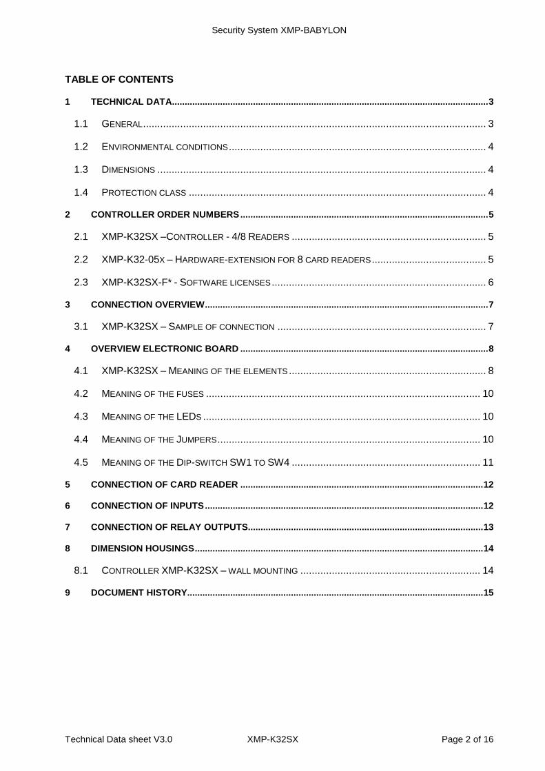
TABLE OF CONTENTS
1 TECHNICAL DATA ............................................................................................................................. 3
1.1 GENERAL ........................................................................................................................ 3
1.2 ENVIRONMENTAL CONDITIONS .......................................................................................... 4
1.3 DIMENSIONS ................................................................................................................... 4
1.4 PROTECTION CLASS ........................................................................................................ 4
2 CONTROLLER ORDER NUMBERS .................................................................................................. 5
2.1 XMP-K32SX –CONTROLLER - 4/8 READERS .................................................................... 5
2.2 XMP-K32-05X – HARDWARE-EXTENSION FOR 8 CARD READERS ........................................ 5
2.3 XMP-K32SX-F* - SOFTWARE LICENSES ........................................................................... 6
3 CONNECTION OVERVIEW ................................................................................................................ 7
3.1 XMP-K32SX – SAMPLE OF CONNECTION ......................................................................... 7
4 OVERVIEW ELECTRONIC BOARD .................................................................................................. 8
4.1 XMP-K32SX – MEANING OF THE ELEMENTS ..................................................................... 8
4.2 MEANING OF THE FUSES ................................................................................................ 10
4.3 MEANING OF THE LEDS ................................................................................................. 10
4.4 MEANING OF THE JUMPERS ............................................................................................ 10
4.5 MEANING OF THE DIP-SWITCH SW1 TO SW4 .................................................................. 11
5 CONNECTION OF CARD READER ................................................................................................ 12
6 CONNECTION OF INPUTS .............................................................................................................. 12
7 CONNECTION OF RELAY OUTPUTS ............................................................................................. 13
8 DIMENSION HOUSINGS .................................................................................................................. 14
8.1 CONTROLLER XMP-K32SX – WALL MOUNTING ............................................................... 14
9 DOCUMENT HISTORY..................................................................................................................... 15
Security System XMP-BABYLON
Technical Data sheet V3.0 XMP-K32SX Page 3 of 16
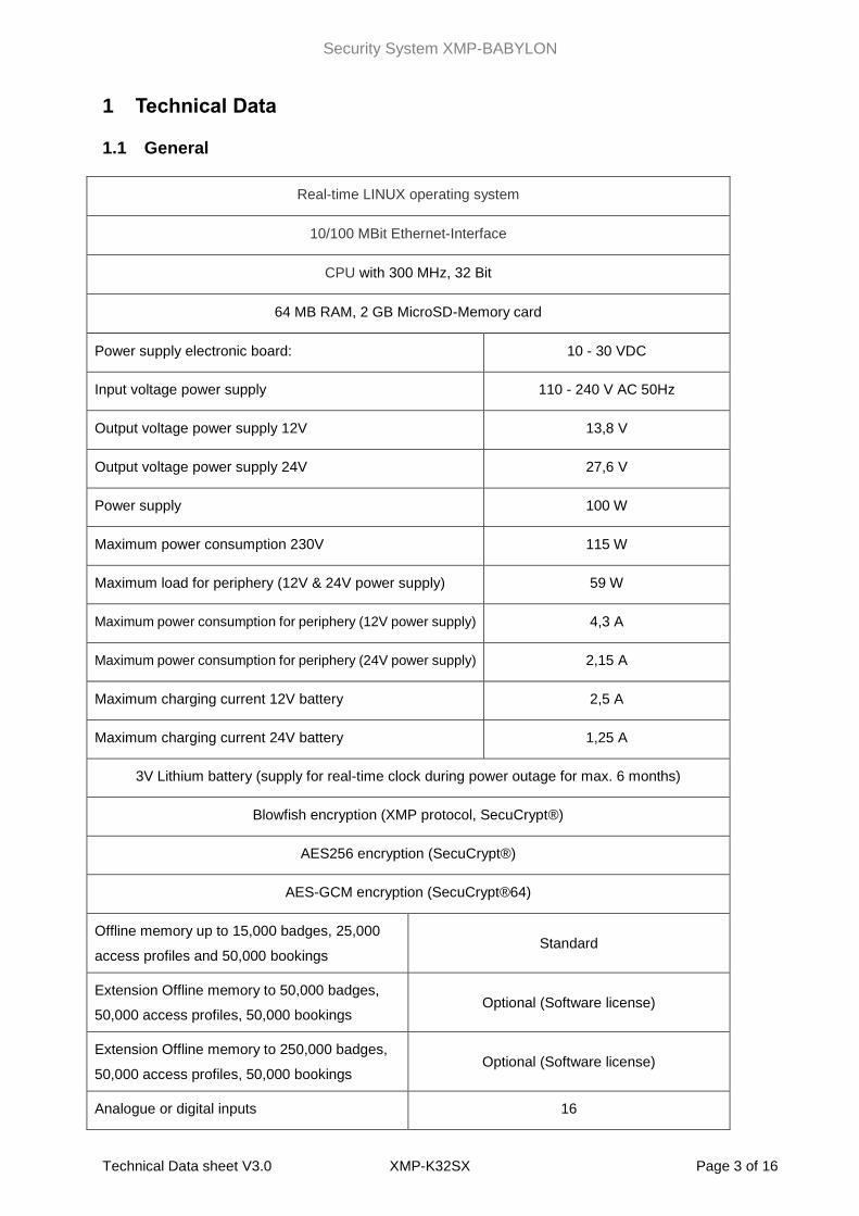
1 Technical Data
1.1 General
Real-time LINUX operating system
10/100 MBit Ethernet-Interface
CPU with 300 MHz, 32 Bit
64 MB RAM, 2 GB MicroSD-Memory card
Power supply electronic board: 10 - 30 VDC
Input voltage power supply 110 - 240 V AC 50Hz
Output voltage power supply 12V 13,8 V
Output voltage power supply 24V 27,6 V
Power supply 100 W
Maximum power consumption 230V 115 W
Maximum load for periphery (12V & 24V power supply) 59 W
Maximum power consumption for periphery (12V power supply) 4,3 A
Maximum power consumption for periphery (24V power supply) 2,15 A
Maximum charging current 12V battery 2,5 A
Maximum charging current 24V battery 1,25 A
3V Lithium battery (supply for real-time clock during power outage for max. 6 months)
Blowfish encryption (XMP protocol, SecuCrypt®)
AES256 encryption (SecuCrypt®)
AES-GCM encryption (SecuCrypt®64)
Offline memory up to 15,000 badges, 25,000
access profiles and 50,000 bookings Standard
Extension Offline memory to 50,000 badges,
50,000 access profiles, 50,000 bookings Optional (Software license)
Extension Offline memory to 250,000 badges,
50,000 access profiles, 50,000 bookings Optional (Software license)
Analogue or digital inputs 16
Security System XMP-BABYLON
Technical Data sheet V3.0 XMP-K32SX Page 4 of 16
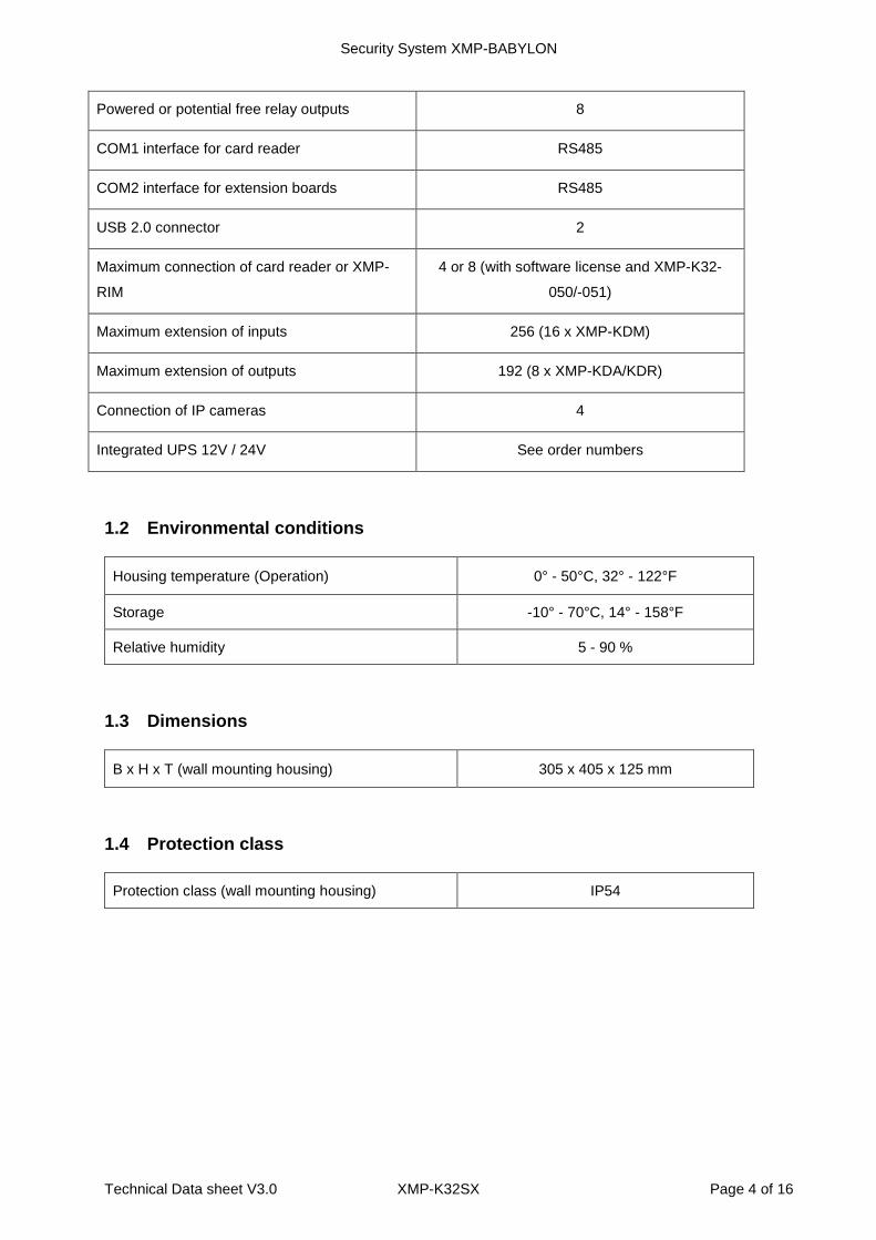
Powered or potential free relay outputs 8
COM1 interface for card reader RS485
COM2 interface for extension boards RS485
USB 2.0 connector 2
Maximum connection of card reader or XMP-
RIM
4 or 8 (with software license and XMP-K32-
050/-051)
Maximum extension of inputs 256 (16 x XMP-KDM)
Maximum extension of outputs 192 (8 x XMP-KDA/KDR)
Connection of IP cameras 4
Integrated UPS 12V / 24V See order numbers
1.2 Environmental conditions
Housing temperature (Operation) 0° - 50°C, 32° - 122°F
Storage -10° - 70°C, 14° - 158°F
Relative humidity 5 - 90 %
1.3 Dimensions
B x H x T (wall mounting housing) 305 x 405 x 125 mm
1.4 Protection class
Protection class (wall mounting housing) IP54
Security System XMP-BABYLON
Technical Data sheet V3.0 XMP-K32SX Page 5 of 16
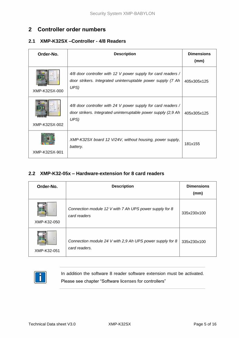
2 Controller order numbers
2.1 XMP-K32SX –Controller - 4/8 Readers
Order-No. Description Dimensions
(mm)
XMP-K32SX-000
4/8 door controller with 12 V power supply for card readers /
door strikers. Integrated uninterruptable power supply (7 Ah
UPS)
405x305x125
XMP-K32SX-002
4/8 door controller with 24 V power supply for card readers /
door strikers. Integrated uninterruptable power supply (2,9 Ah
UPS)
405x305x125
XMP-K32SX-901
XMP-K32SX board 12 V/24V, without housing, power supply,
battery. 181x155
2.2 XMP-K32-05x – Hardware-extension for 8 card readers
Order-No. Description Dimensions
(mm)
XMP-K32-050
Connection module 12 V with 7 Ah UPS power supply for 8
card readers 335x230x100
XMP-K32-051
Connection module 24 V with 2,9 Ah UPS power supply for 8
card readers.
335x230x100
In addition the software 8 reader software extension must be activated.
Please see chapter “Software licenses for controllers”
Security System XMP-BABYLON
Technical Data sheet V3.0 XMP-K32SX Page 6 of 16
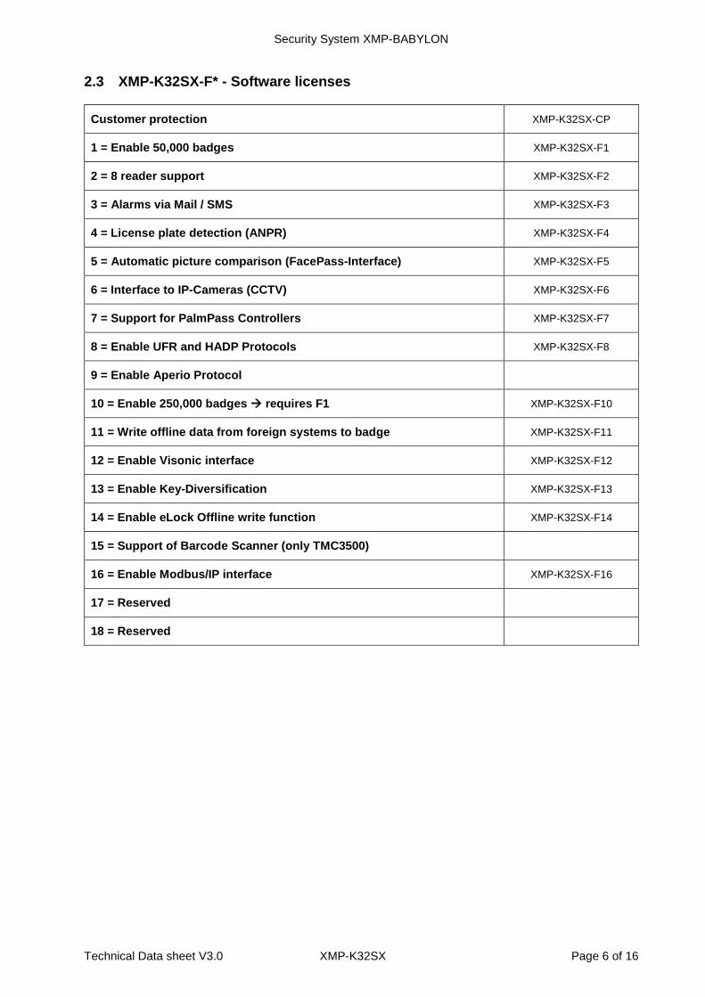
2.3 XMP-K32SX-F* - Software licenses
Customer protection XMP-K32SX-CP
1 = Enable 50,000 badges XMP-K32SX-F1
2 = 8 reader support XMP-K32SX-F2
3 = Alarms via Mail / SMS XMP-K32SX-F3
4 = License plate detection (ANPR) XMP-K32SX-F4
5 = Automatic picture comparison (FacePass-Interface) XMP-K32SX-F5
6 = Interface to IP-Cameras (CCTV) XMP-K32SX-F6
7 = Support for PalmPass Controllers XMP-K32SX-F7
8 = Enable UFR and HADP Protocols XMP-K32SX-F8
9 = Enable Aperio Protocol
10 = Enable 250,000 badges requires F1 XMP-K32SX-F10
11 = Write offline data from foreign systems to badge XMP-K32SX-F11
12 = Enable Visonic interface XMP-K32SX-F12
13 = Enable Key-Diversification XMP-K32SX-F13
14 = Enable eLock Offline write function XMP-K32SX-F14
15 = Support of Barcode Scanner (only TMC3500)
16 = Enable Modbus/IP interface XMP-K32SX-F16
17 = Reserved
18 = Reserved
Security System XMP-BABYLON
Technical Data sheet V3.0 XMP-K32SX Page 7 of 16
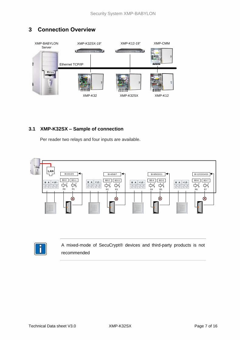
3 Connection Overview
3.1 XMP-K32SX – Sample of connection
Per reader two relays and four inputs are available.
LAN
R0 R1
BO-1B0-0
BI-0/1/2/3
R2 R3
BO-3B0-2
BI-4/5/6/7
R4 R5
BO-5B0-4
BI-8/9/10/11
R6 R7
BO-7B0-6
BI-12/13/14/15
+ L0 -B A + L1 -B A + L2 -B A + L3 -B A
A mixed-mode of SecuCrypt® devices and third-party products is not
recommended
XMP-BABYLON
Server
Ethernet TCP/IP
XMP-K12XMP-K32 XMP-K32SX
XMP-K32SX-19" XMP-K12-19" XMP-CMM
Security System XMP-BABYLON
Technical Data sheet V3.0 XMP-K32SX Page 8 of 16
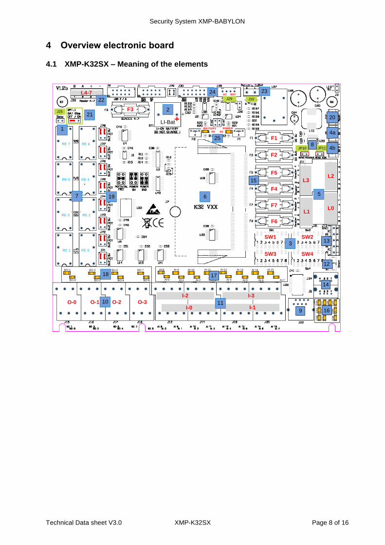
4 Overview electronic board
4.1 XMP-K32SX – Meaning of the elements
J25
JP10 JP11
F1
F2
F3
F4
F5
F6
F7
D3
2
D3
3
D3
4
D3
5
D3
6
D3
7
D3
8
D3
0
D3
1
D2
8
D2
9
BO-0
BO-1
BO-2
BO-3
BO-4
BO-5
BO-6
BO-7
AI-0
AI-8
AI-1
AI-9
AI-2
AI-10
AI-3
AI-11
AI-4
AI-12
AI-5
AI-13
AI-6
AI-14
AI-7
AI-15
4a
16
14
9
15
17
19
1
7
18
RE 0RE 1
RE 2RE 3
RE 4RE 5
RE 6RE 7
212
6
O-0 O-1 O-2 O-3
I-2
I-0 I-1
I-3
1110
20
3
SW1 SW2
SW3 SW4
5
L0
L2
L1
7
L4-7
22
4b
LI-Bat
J10
2324J29
AC BAT
POWER
D5
BATTERY
D6
25
8
L3
13
12
Security System XMP-BABYLON
Technical Data sheet V3.0 XMP-K32SX Page 9 of 16
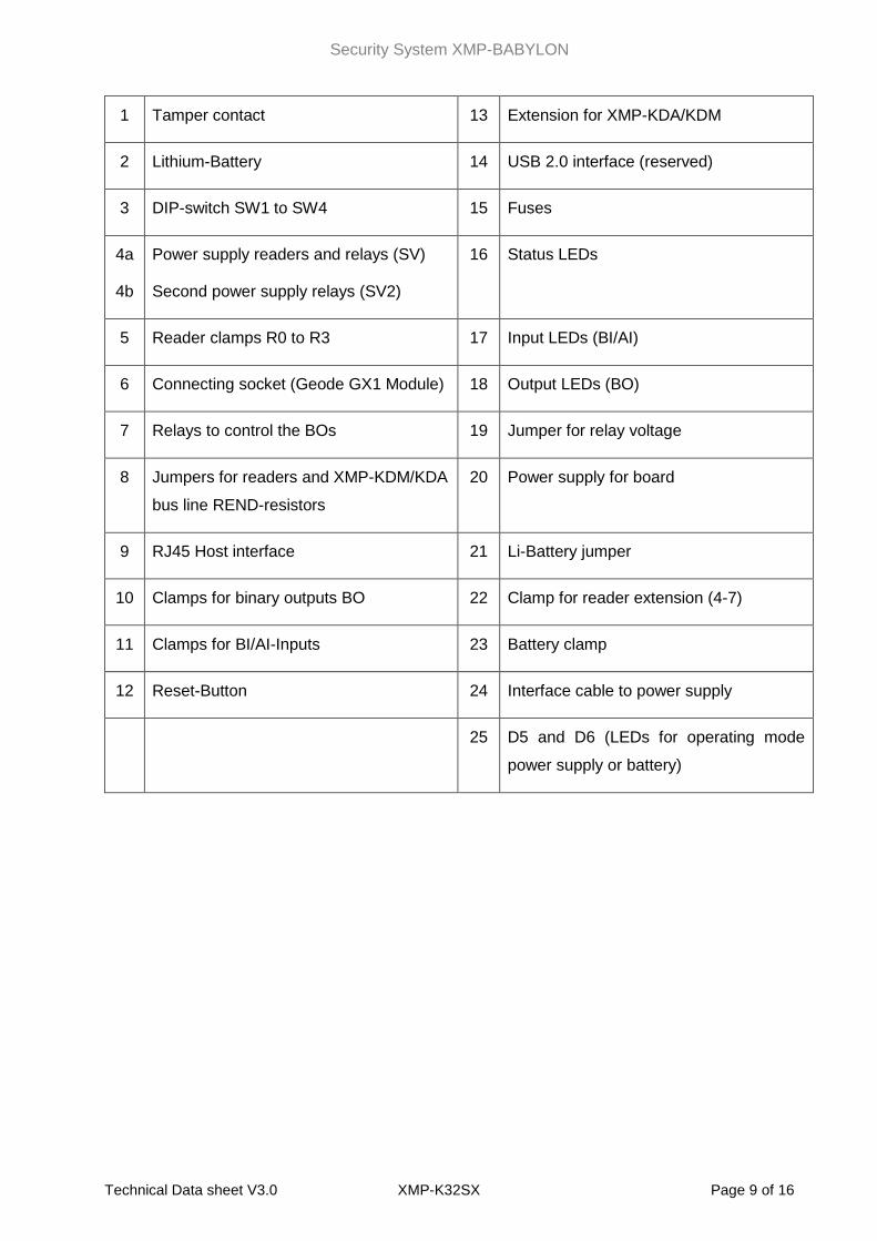
1 Tamper contact 13 Extension for XMP-KDA/KDM
2 Lithium-Battery 14 USB 2.0 interface (reserved)
3 DIP-switch SW1 to SW4 15 Fuses
4a
4b
Power supply readers and relays (SV)
Second power supply relays (SV2)
16 Status LEDs
5 Reader clamps R0 to R3 17 Input LEDs (BI/AI)
6 Connecting socket (Geode GX1 Module) 18 Output LEDs (BO)
7 Relays to control the BOs 19 Jumper for relay voltage
8 Jumpers for readers and XMP-KDM/KDA
bus line REND-resistors
20 Power supply for board
9 RJ45 Host interface 21 Li-Battery jumper
10 Clamps for binary outputs BO 22 Clamp for reader extension (4-7)
11 Clamps for BI/AI-Inputs 23 Battery clamp
12 Reset-Button 24 Interface cable to power supply
25 D5 and D6 (LEDs for operating mode
power supply or battery)
Security System XMP-BABYLON
Technical Data sheet V3.0 XMP-K32SX Page 10 of 16
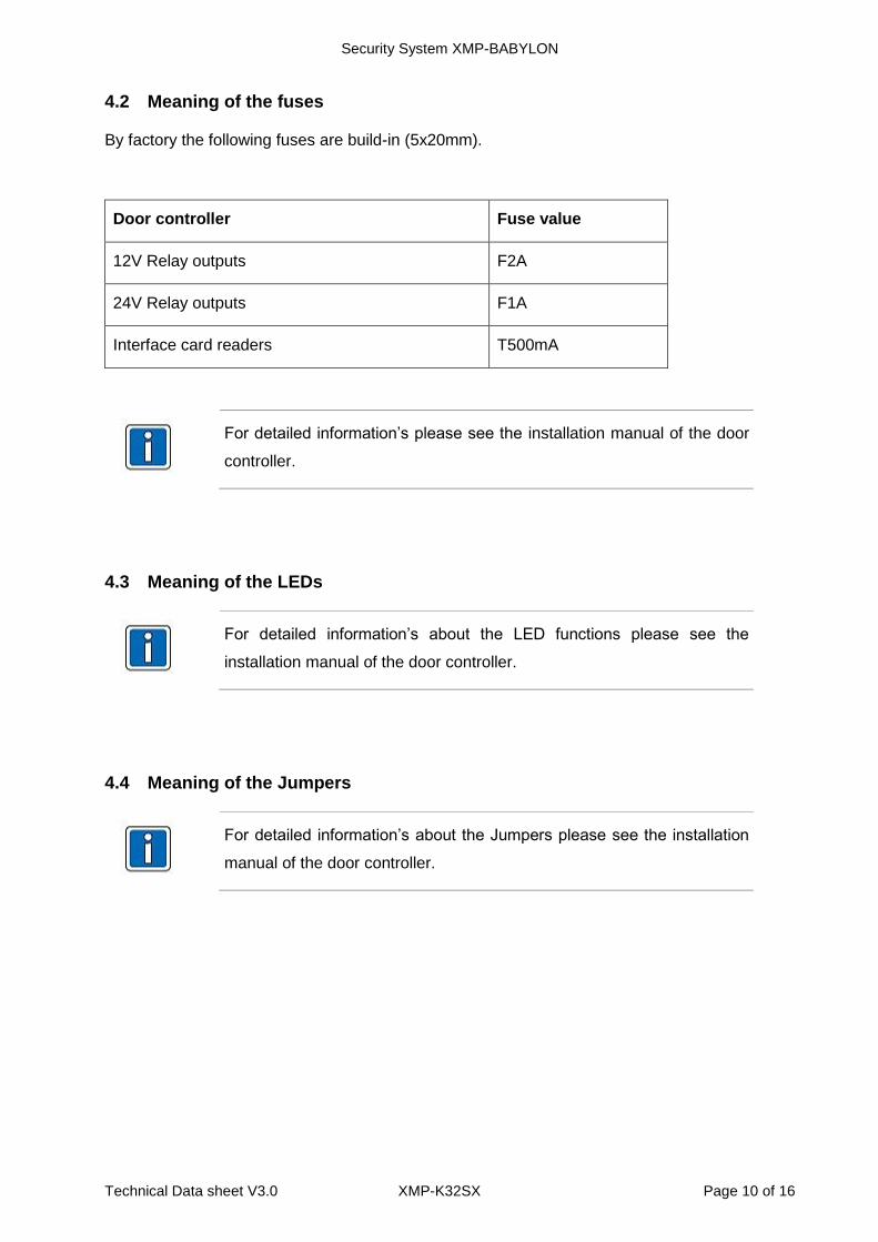
4.2 Meaning of the fuses
By factory the following fuses are build-in (5x20mm).
Door controller Fuse value
12V Relay outputs F2A
24V Relay outputs F1A
Interface card readers T500mA
For detailed information’s please see the installation manual of the door
controller.
4.3 Meaning of the LEDs
For detailed information’s about the LED functions please see the
installation manual of the door controller.
4.4 Meaning of the Jumpers
For detailed information’s about the Jumpers please see the installation
manual of the door controller.
Security System XMP-BABYLON
Technical Data sheet V3.0 XMP-K32SX Page 11 of 16
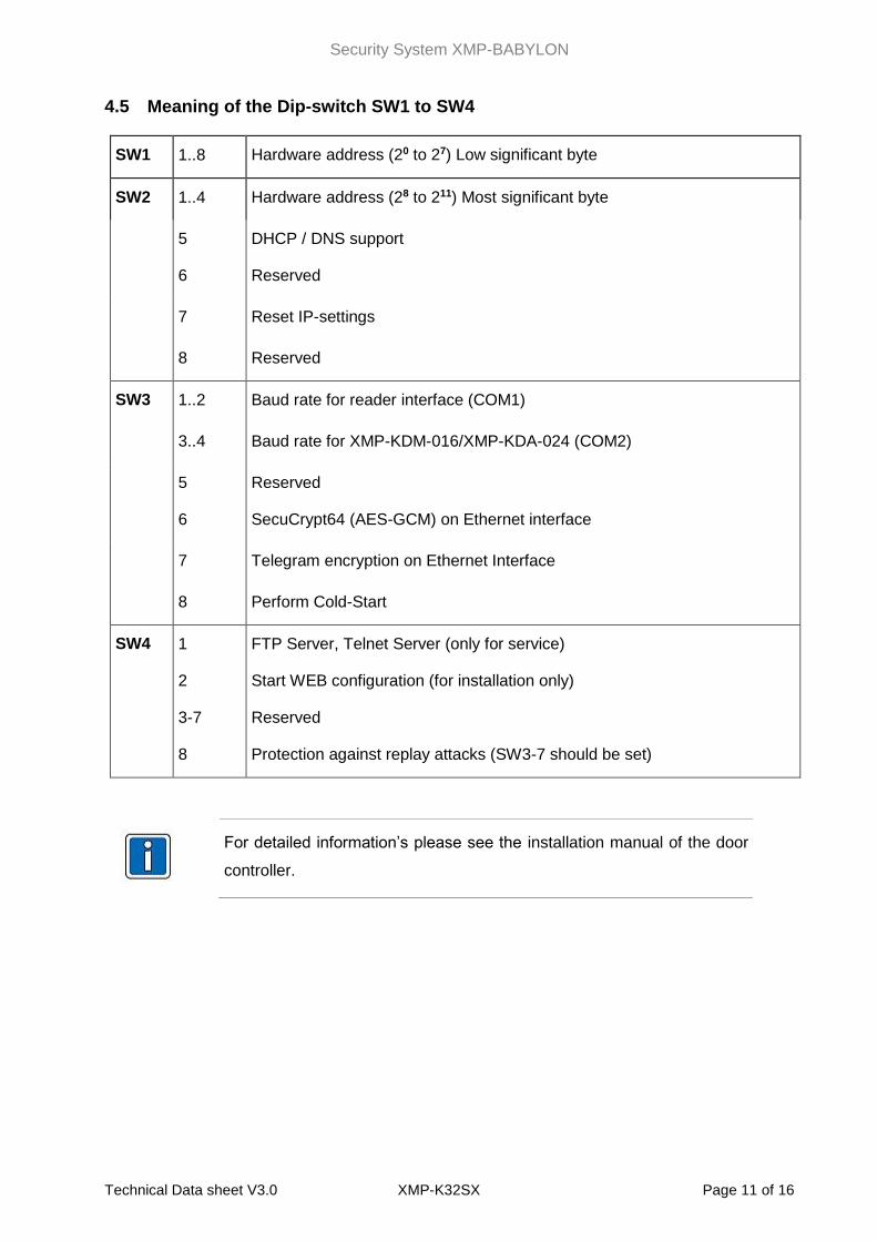
4.5 Meaning of the Dip-switch SW1 to SW4
SW1 1..8 Hardware address (20 to 27) Low significant byte
SW2 1..4 Hardware address (28 to 211) Most significant byte
5
6
DHCP / DNS support
Reserved
7 Reset IP-settings
8 Reserved
SW3 1..2 Baud rate for reader interface (COM1)
3..4 Baud rate for XMP-KDM-016/XMP-KDA-024 (COM2)
5
6
Reserved
SecuCrypt64 (AES-GCM) on Ethernet interface
7 Telegram encryption on Ethernet Interface
8 Perform Cold-Start
SW4 1
2
3-7
8
FTP Server, Telnet Server (only for service)
Start WEB configuration (for installation only)
Reserved
Protection against replay attacks (SW3-7 should be set)
For detailed information’s please see the installation manual of the door
controller.
Security System XMP-BABYLON
Technical Data sheet V3.0 XMP-K32SX Page 12 of 16
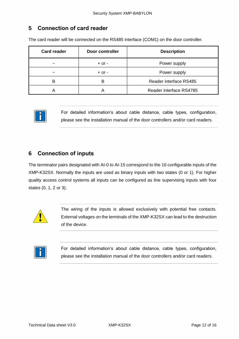
5 Connection of card reader
The card reader will be connected on the RS485 interface (COM1) on the door controller.
Card reader Door controller Description
~ + or - Power supply
~ + or - Power supply
B B Reader interface RS485
A A Reader interface RS4785
For detailed information’s about cable distance, cable types, configuration,
please see the installation manual of the door controllers and/or card readers.
6 Connection of inputs
The terminator pairs designated with AI-0 to AI-15 correspond to the 16 configurable inputs of the
XMP-K32SX. Normally the inputs are used as binary inputs with two states (0 or 1). For higher
quality access control systems all inputs can be configured as line supervising inputs with four
states (0, 1, 2 or 3).
The wiring of the inputs is allowed exclusively with potential free contacts.
External voltages on the terminals of the XMP-K32SX can lead to the destruction
of the device.
For detailed information’s about cable distance, cable types, configuration,
please see the installation manual of the door controllers and/or card readers.
Security System XMP-BABYLON
Technical Data sheet V3.0 XMP-K32SX Page 13 of 16
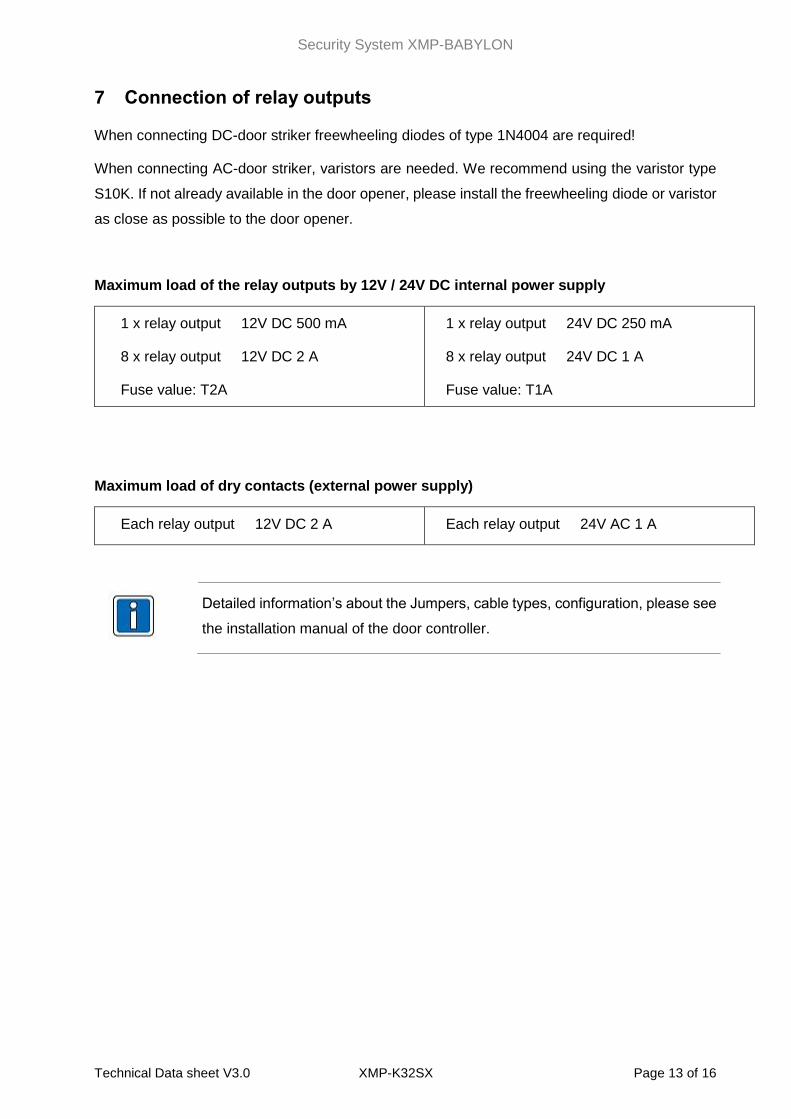
7 Connection of relay outputs
When connecting DC-door striker freewheeling diodes of type 1N4004 are required!
When connecting AC-door striker, varistors are needed. We recommend using the varistor type
S10K. If not already available in the door opener, please install the freewheeling diode or varistor
as close as possible to the door opener.
Maximum load of the relay outputs by 12V / 24V DC internal power supply
1 x relay output 12V DC 500 mA
8 x relay output 12V DC 2 A
Fuse value: T2A
1 x relay output 24V DC 250 mA
8 x relay output 24V DC 1 A
Fuse value: T1A
Maximum load of dry contacts (external power supply)
Each relay output 12V DC 2 A Each relay output 24V AC 1 A
Detailed information’s about the Jumpers, cable types, configuration, please see
the installation manual of the door controller.
Security System XMP-BABYLON
Technical Data sheet V3.0 XMP-K32SX Page 14 of 16
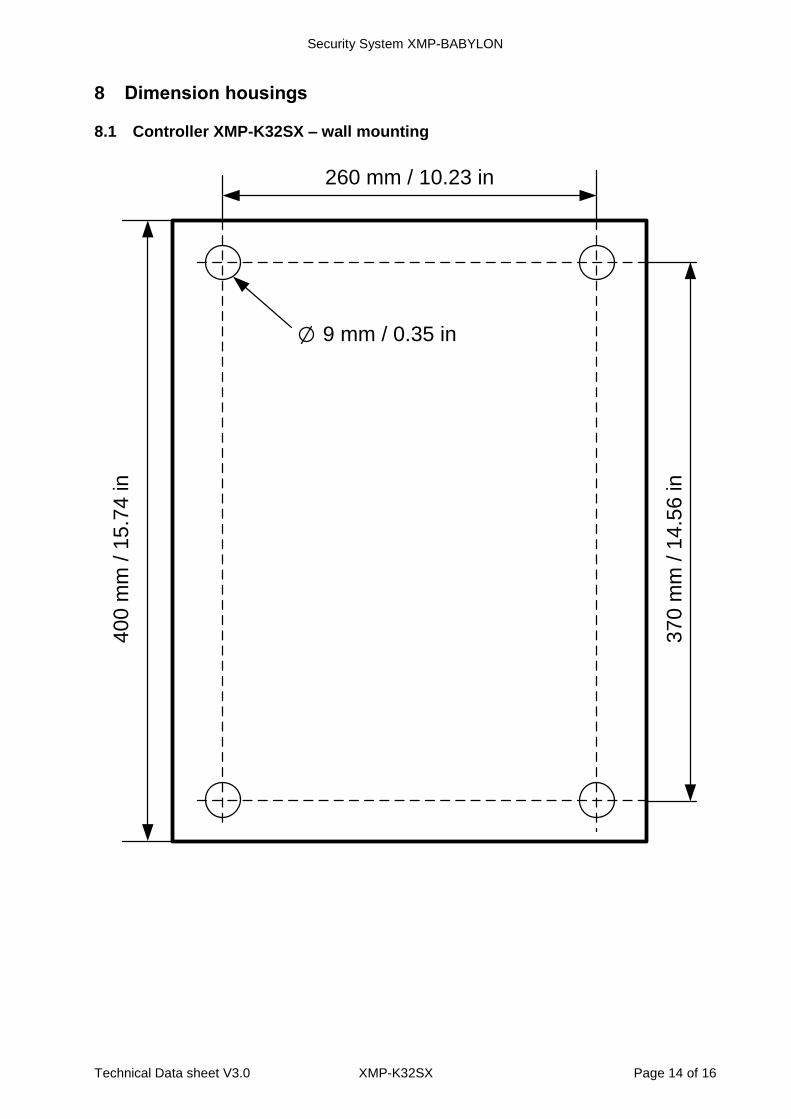
8 Dimension housings
8.1 Controller XMP-K32SX – wall mounting
9 mm / 0.35 in
260 mm / 10.23 in
40
0 m
m / 1
5.7
4 in
37
0 m
m / 1
4.5
6 in
Security System XMP-BABYLON
Technical Data sheet V3.0 XMP-K32SX Page 15 of 16
9 Document History
Version Date Description
V3.0 04.01.2017 New design of controller data sheets.
COPYRIGHT © AUTEC GMBH 2017
AUTEC Gesellschaft für Automationstechnik mbH
Bahnhofstraße 57-61b
D-55234 Framersheim
Germany
Tel.: +49 (0)6733-9201-0
Fax: +49 (0)6733-9201-91
e-mail: [email protected]
Internet: www.autec-gmbh.de
www.autec-security.com
Security System XMP-BABYLON
Technical Data sheet V3.0 XMP-K32SX Page 16 of 16
Copyright © 2017 AUTEC Gesellschaft für Automationstechnik mbH - All rights reserved
Revision: January 2017 - This issue replaces all previous issues. Availability, errors and specifications are subject to
change without notice.
The information presented in this document is for informational purposes only and may contain technical inaccuracies,
omissions and typographical errors.
Transmitting as well as copying of this document, utilization and communication of its contents are not
permitted, if not explicitly allowed. Contravention obliges for compensation. All rights reserved for the case of
patent allocation or registered design registration.
The list of information in this manual occurs according to best knowledge and conscience. AUTEC gives no guarantee
for the correctness and completeness of information in this manual. In particular, AUTEC cannot be made liable for
consequential damages, which are due to erroneous or incomplete information.
Since mistakes - in spite of all efforts - cannot be avoided completely, we appreciate hints at any time.
The installation recommendations gained in this manual presume the most favorable general conditions. AUTEC gives
no guarantee for the perfect function of an installation in system foreign environments.
AUTEC gives no guarantee that the information of this document is free from other industrial property rights. With this
document AUTEC grants no licenses for own or other patents or other industrial property rights.