XI/ON Series Remote I/O - Advanced Bionics€¦ · XI/ON Series Remote I/O XI/ON Series Remote I/O...
47
V7-T4-58 Volume 7—Logic Control, Operator Interface and Connectivity Solutions CA08100008E—June 2013 www.eaton.com 4 4 4 4 4 4 4 4 4 4 4 4 4 4 4 4 4 4 4 4 4 4 4 4 4 4 4 4 4 4 4.5 PLC, I/O and Communications Products XI/ON Series Remote I/O XI/ON Series Remote I/O Contents Description Page XI/ON Series Remote I/O Product Selection Guide . . . . . . . . . . . . . . . . . V7-T4-59 Catalog Number Selection . . . . . . . . . . . . . . . . V7-T4-60 System Overview . . . . . . . . . . . . . . . . . . . . . . . V7-T4-62 Product Selection . . . . . . . . . . . . . . . . . . . . . . . V7-T4-66 Accessories . . . . . . . . . . . . . . . . . . . . . . . . . . . V7-T4-75 Technical Data and Specifications . . . . . . . . . . V7-T4-76 Connection Diagrams . . . . . . . . . . . . . . . . . . . . V7-T4-89 Dimensions . . . . . . . . . . . . . . . . . . . . . . . . . . . V7-T4-101 Product Overview Whether for controlling movements, measuring temperature or speed, or logging currents and voltages, the application ranges for remote I/Os are as extensive as the different applications involved. They are used wherever decentralized signal processing is the essential element of the automation concept. Thanks to the high modularity of the XI/ON system and the wide range of functions, Eaton is able to offer the right I/O solution for every application. XI/ON: A modular concept with simple handling— adaptable to any application, intelligent and ready for future developments. Standards and Certifications ● UL File No. E205091 ● UL CCN—NRAQ, NRAQ7 ● cULus ● CE ● RoHS www.comoso.com
Transcript of XI/ON Series Remote I/O - Advanced Bionics€¦ · XI/ON Series Remote I/O XI/ON Series Remote I/O...

V7-T4-58 Volume 7—Logic Control, Operator Interface and Connectivity Solutions CA08100008E—June 2013 www.eaton.com
4
4
4
4
4
4
4
4
4
4
4
4
4
4
4
4
4
4
4
4
4
4
4
4
4
4
4
4
4
4
4.5 PLC, I/O and Communications Products
XI/ON Series Remote I/O
XI/ON Series Remote I/O ContentsDescription Page
XI/ON Series Remote I/O Product Selection Guide . . . . . . . . . . . . . . . . . V7-T4-59Catalog Number Selection . . . . . . . . . . . . . . . . V7-T4-60System Overview . . . . . . . . . . . . . . . . . . . . . . . V7-T4-62Product Selection . . . . . . . . . . . . . . . . . . . . . . . V7-T4-66Accessories . . . . . . . . . . . . . . . . . . . . . . . . . . . V7-T4-75Technical Data and Specifications . . . . . . . . . . V7-T4-76Connection Diagrams . . . . . . . . . . . . . . . . . . . . V7-T4-89Dimensions . . . . . . . . . . . . . . . . . . . . . . . . . . . V7-T4-101
Product OverviewWhether for controlling movements, measuring temperature or speed, or logging currents and voltages, the application ranges for remote I/Os are as extensive as the different applications involved. They are used wherever decentralized signal processing is the essential element of the automation concept.
Thanks to the high modularity of the XI/ON system and the wide range of functions, Eaton is able to offer the right I/O solution for every application. XI/ON: A modular concept with simple handling— adaptable to any application, intelligent and ready for future developments.
Standards and Certifications● UL File No. E205091● UL CCN—NRAQ, NRAQ7● cULus● CE● RoHS
www.comoso.com
Volume 7—Logic Control, Operator Interface and Connectivity Solutions CA08100008E—June 2013 www.eaton.com V7-T4-59
4
4
4
4
4
4
4
4
4
4
4
4
4
4
4
4
4
4
4
4
4
4
4
4
4
4
4
4
4
4
4.5PLC, I/O and Communications Products
XI/ON Series Remote I/O
Product Selection Guide
XI/ON Series Remote I/O
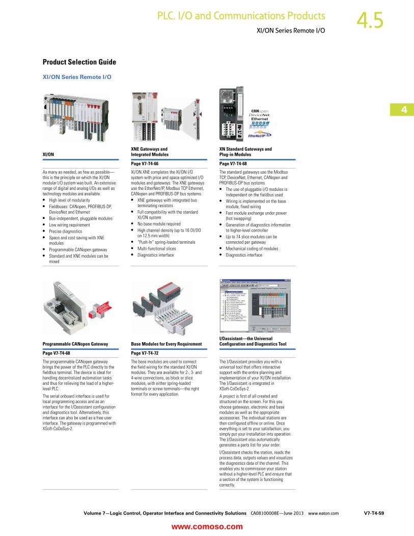
XI/ONXNE Gateways and Integrated Modules
XN Standard Gateways and Plug-in Modules
Page V7-T4-66 Page V7-T4-68
As many as needed, as few as possible—this is the principle on which the XI/ON modular I/O system was built. An extensive range of digital and analog I/Os as well as technology modules are available.● High level of modularity● Fieldbuses: CANopen, PROFIBUS-DP,
DeviceNet and Ethernet● Bus-independent, pluggable modules● Low wiring requirement● Precise diagnostics● Space and cost saving with XNE
modules ● Programmable CANopen gateway● Standard and XNE modules can be
mixed
XI/ON XNE completes the XI/ON I/O system with price and space optimized I/O modules and gateways. The XNE gateways use the EtherNet/IP, Modbus TCP Ethernet, CANopen and PROFIBUS-DP bus systems.● XNE gateways with integrated bus
terminating resistors● Full compatibility with the standard
XI/ON system● No base module required ● High channel density (up to 16 DI/DO
on 12.5 mm width) ● “Push-In” spring-loaded terminals● Multi-functional slices● Diagnostics interface
The standard gateways use the Modbus TCP, DeviceNet, Ethernet, CANopen and PROFIBUS-DP bus systems. ● The use of pluggable I/O modules is
independent on the fieldbus used● Wiring is implemented on the base
module, fixed wiring● Fast module exchange under power
(hot swapping)● Generation of diagnostics information
to higher-level controller ● Up to 74 slice modules can be
connected per gateway● Mechanical coding of modules● Diagnostics interface
Programmable CANopen Gateway Base Modules for Every RequirementI/Oassistant—the Universal Configuration and Diagnostics Tool
Page V7-T4-68 Page V7-T4-72
The programmable CANopen gateway brings the power of the PLC directly to the fieldbus terminal. The device is ideal for handling decentralized automation tasks and thus for relieving the load of a higher-level PLC.
The serial onboard interface is used for local programming access and as an interface for the I/Oassistant configuration and diagnostics tool. Alternatively, this interface can also be used as a free user interface. The gateway is programmed with XSoft-CoDeSys-2.
The base modules are used to connect the field wiring for the standard XI/ON modules. They are available for 2-, 3- and 4-wire connections, as block or slice modules, with either spring-loaded terminals or screw terminals—the right format for every application.
The I/Oassistant provides you with a universal tool that offers interactive support with the entire planning and implementation of your XI/ON installation. The I/Oassistant is integrated in XSoft-CoDeSys-2.
A project is first of all created and structured on the screen. For this you choose gateways, electronic and base modules as well as the appropriate accessories. The individual stations are then configured offline or online. Once everything is set to your satisfaction, you simply put your installation into operation. The I/Oassistant also automatically generates a parts list for your order.
I/Oassistant checks the station, reads the process data, outputs values and visualizes the diagnostics data of the channel. This enables you to commission your station without a higher-level PLC and ensure that a section of the system is functioning correctly.
www.comoso.com
V7-T4-60 Volume 7—Logic Control, Operator Interface and Connectivity Solutions CA08100008E—June 2013 www.eaton.com
4
4
4
4
4
4
4
4
4
4
4
4
4
4
4
4
4
4
4
4
4
4
4
4
4
4
4
4
4
4
4.5 PLC, I/O and Communications Products
XI/ON Series Remote I/O
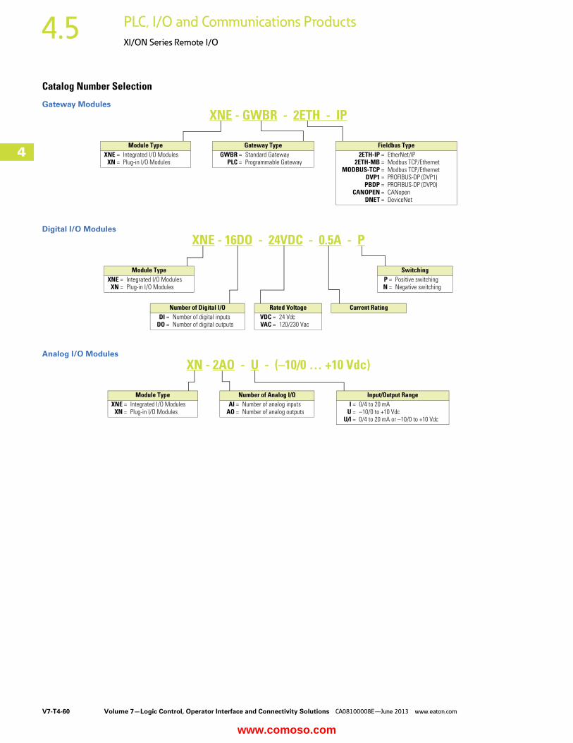
Catalog Number Selection
Gateway Modules
Digital I/O Modules
Analog I/O Modules
Module TypeXNE = Integrated I/O Modules
XN = Plug-in I/O Modules
XNE - GWBR - 2ETH - IP
Fieldbus Type2ETH-IP = EtherNet/IP
2ETH-MB = Modbus TCP/EthernetMODBUS-TCP = Modbus TCP/Ethernet
DVP1 = PROFIBUS-DP (DVP1)PBDP = PROFIBUS-DP (DVP0)
CANOPEN = CANopenDNET = DeviceNet
Gateway TypeGWBR = Standard Gateway
PLC = Programmable Gateway
XNE - 16DO - 24VDC - 0.5A - P
Number of Digital I/ODI = Number of digital inputs
DO = Number of digital outputs
Rated VoltageVDC = 24 VdcVAC = 120/230 Vac
SwitchingP = Positive switchingN = Negative switching
Module TypeXNE = Integrated I/O Modules
XN = Plug-in I/O Modules
Current Rating
XN - 2AO - U - (–10/0 … +10 Vdc)
Input/Output RangeI = 0/4 to 20 mA
U = –10/0 to +10 VdcU/I = 0/4 to 20 mA or –10/0 to +10 Vdc
Number of Analog I/OAI = Number of analog inputs
AO = Number of analog outputs
Module TypeXNE = Integrated I/O Modules
XN = Plug-in I/O Modules
www.comoso.com
Volume 7—Logic Control, Operator Interface and Connectivity Solutions CA08100008E—June 2013 www.eaton.com V7-T4-61
4
4
4
4
4
4
4
4
4
4
4
4
4
4
4
4
4
4
4
4
4
4
4
4
4
4
4
4
4
4
4.5PLC, I/O and Communications Products
XI/ON Series Remote I/O
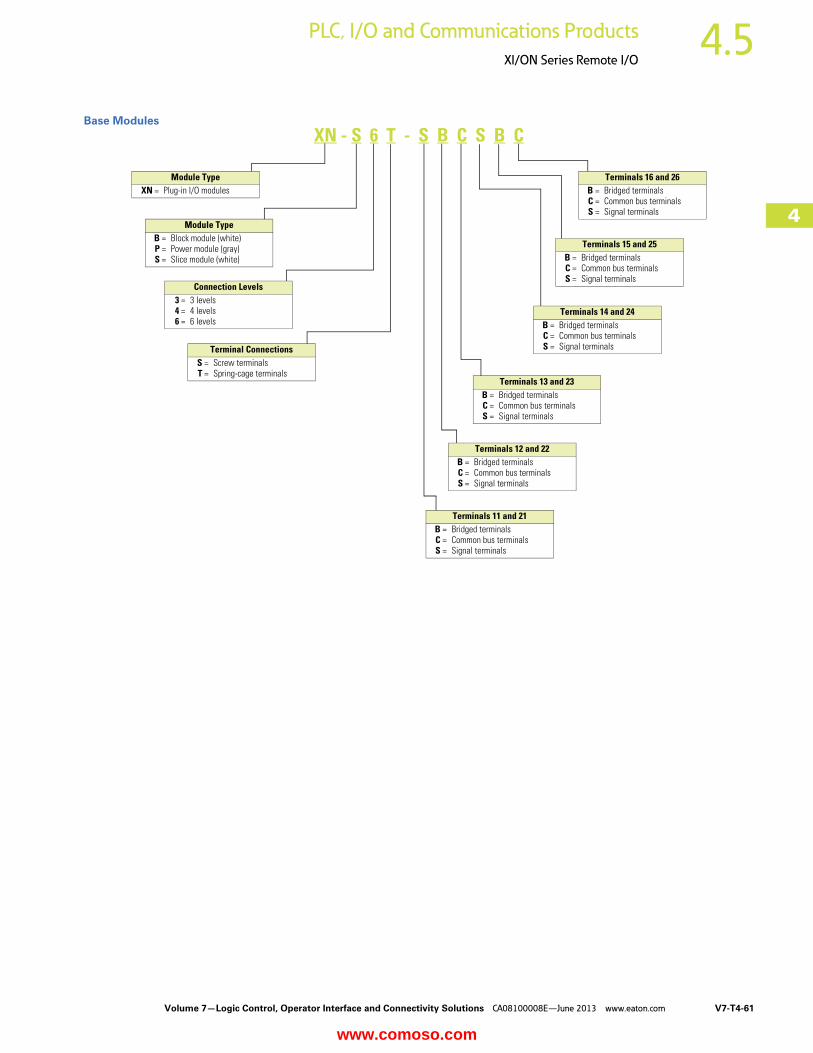
Base Modules
Module TypeB = Block module (white)P = Power module (gray)S = Slice module (white)
Module TypeXN = Plug-in I/O modules
XN - S 6 T - S B C S B C
Terminal ConnectionsS = Screw terminalsT = Spring-cage terminals
Connection Levels3 = 3 levels4 = 4 levels6 = 6 levels
Terminals 16 and 26B = Bridged terminalsC = Common bus terminalsS = Signal terminals
Terminals 15 and 25B = Bridged terminalsC = Common bus terminalsS = Signal terminals
Terminals 14 and 24B = Bridged terminalsC = Common bus terminalsS = Signal terminals
Terminals 13 and 23B = Bridged terminalsC = Common bus terminalsS = Signal terminals
Terminals 12 and 22B = Bridged terminalsC = Common bus terminalsS = Signal terminals
Terminals 11 and 21B = Bridged terminalsC = Common bus terminalsS = Signal terminals
www.comoso.com
V7-T4-62 Volume 7—Logic Control, Operator Interface and Connectivity Solutions CA08100008E—June 2013 www.eaton.com
4
4
4
4
4
4
4
4
4
4
4
4
4
4
4
4
4
4
4
4
4
4
4
4
4
4
4
4
4
4
4.5 PLC, I/O and Communications Products
XI/ON Series Remote I/O
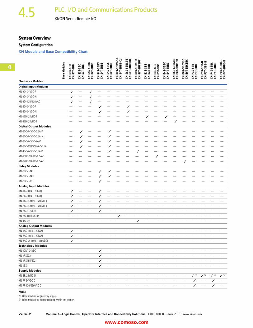
System OverviewSystem Configuration
XN Module and Base Compatibility Chart
Notes1 Base module for gateway supply.2 Base module for bus refreshing within the station.
Bas
e M
odul
es
XN-S
3S-S
BB
XN-S
3T-S
BB
XN-S
3S-S
BC
XN-S
3T-S
BC
XN-S
4S-S
BB
CXN
-S4T
-SB
BC
XN-S
4S-S
BB
SXN
-S4T
-SB
BS
XN-S
4S-S
BCS
XN-S
4T-S
BCS
XN-S
4S-S
BB
S-CJ
XN-S
4T-S
BB
S-CJ
XN-S
6S-S
BB
SBB
XN-S
6T-S
BB
SBB
XN-S
6S-S
BCS
BC
XN-S
6T-S
BCS
BC
XN-B
3S-S
BB
XN-B
3T-S
BB
XN-B
3S-S
BC
XN-B
3T-S
BC
XN-B
4S-S
BB
CXN
-B4T
-SB
BC
XN-B
6S-S
BB
SBB
XN-B
6T-S
BB
SBB
XN-B
6S-S
BCS
BC
XN-B
6T-S
BCS
BC
XN-P
3S-S
BB
XN-P
3T-S
BB
XN-P
3S-S
BB
-BXN
-P3T
.-SB
B-B
XN-P
4S-S
BB
CXN
-P4T
-SB
BC
XN-P
4S-S
BB
C-B
XN-P
4T-S
BB
C-B
Electronics Modules
Digital Input Modules
XN-2DI-24VDC-P ✓ — ✓ — — — — — — — — — — — — — —
XN-2DI-24VDC-N ✓ — ✓ — — — — — — — — — — — — — —
XN-2DI-120/230VAC ✓ — ✓ — — — — — — — — — — — — — —
XN-4DI-24VDC-P — — — ✓ — — ✓ — — — — — — — — — —
XN-4DI-24VDC-N — — — ✓ — — ✓ — — — — — — — — — —
XN-16DI-24VDC-P — — — — — — — — ✓ — ✓ — — — — — —
XN-32DI-24VDC-P — — — — — — — — — — — ✓ — — — — —
Digital Output Modules
XN-2DO-24VDC-0.5A-P — ✓ — — ✓ — — — — — — — — — — — —
XN-2DO-24VDC-0.5A-N — ✓ — — ✓ — — — — — — — — — — — —
XN-2DO-24VDC-2A-P — ✓ — — ✓ — — — — — — — — — — — —
XN-2DO-120/230VAC-0.5A — ✓ — — ✓ — — — — — — — — — — — —
XN-4DO-24VDC-0.5A-P — — — — ✓ — — ✓ — — — — — — — — —
XN-16DO-24VDC-0.5A-P — — — — — — — — — ✓ — — — — — — —
XN-32DO-24VDC-0.5A-P — — — — — — — — — — — — ✓ — — — —
Relay Modules
XN-2DO-R-NC — — — ✓ ✓ — — — — — — — — — — — —
XN-2DO-R-NO — — — ✓ ✓ — — — — — — — — — — — —
XN-2DO-R-CO — — — ✓ — — — — — — — — — — — — —
Analog Input Modules
XN-1AI-I(0/4…20MA) ✓ — — ✓ — — — — — — — — — — — — —
XN-2AI-I(0/4…20MA) ✓ — — ✓ — — — — — — — — — — — — —
XN-1AI-U(-10/0…+10VDC) ✓ — — ✓ — — — — — — — — — — — — —
XN-2AI-U(-10/0…+10VDC) ✓ — — ✓ — — — — — — — — — — — — —
XN-2AI-PT/NI-2/3 ✓ — — ✓ — — — — — — — — — — — — —
XN-2AI-THERMO-PI — — — — — ✓ — — — — — — — — — — —
XN-4AI-U/I — — — — — — — ✓ — — — — — — — — —
Analog Output Modules
XN-1AO-I(0/4…20MA) ✓ — — — — — — — — — — — — — — — —
XN-2AO-I(0/4…20MA) ✓ — — — — — — — — — — — — — — — —
XN-2AO-U(-10/0…+10VDC) ✓ — — — — — — — — — — — — — — — —
Technology Modules
XN-1CNT-24VDC — — — ✓ — — — — — — — — — — — — —
XN-1RS232 — — — ✓ — — — — — — — — — — — — —
XN-1RS485/422 — — — ✓ — — — — — — — — — — — — —
XN-1SSI — — — ✓ — — — — — — — — — — — — —
Supply Modules
XN-BR-24VDC-D — — — — — — — — — — — — — ✓ 1 ✓ 2 ✓ 1 ✓ 2
XN-PF-24VDC-D — — — — — — — — — — — — — ✓ — ✓ —
XN-PF-120/230VAC-D — — — — — — — — — — — — — ✓ — ✓ —
www.comoso.com
Volume 7—Logic Control, Operator Interface and Connectivity Solutions CA08100008E—June 2013 www.eaton.com V7-T4-63
4
4
4
4
4
4
4
4
4
4
4
4
4
4
4
4
4
4
4
4
4
4
4
4
4
4
4
4
4
4
4.5PLC, I/O and Communications Products
XI/ON Series Remote I/O
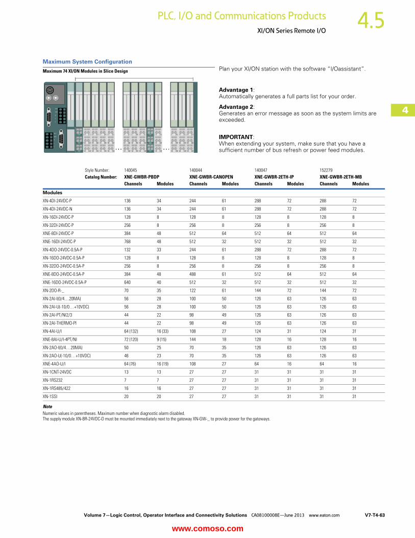
Maximum System Configuration Plan your XI/ON station with the software “I/Oassistant”.
Advantage 1: Automatically generates a full parts list for your order.
Advantage 2: Generates an error message as soon as the system limits are exceeded.
IMPORTANT:When extending your system, make sure that you have a sufficient number of bus refresh or power feed modules.
NoteNumeric values in parentheses. Maximum number when diagnostic alarm disabled.The supply module XN-BR-24VDC-D must be mounted immediately next to the gateway XN-GW-_ to provide power for the gateways.
Style Number: 140045 140044 140047 152279Catalog Number: XNE-GWBR-PBDP XNE-GWBR-CANOPEN XNE-GWBR-2ETH-IP XNE-GWBR-2ETH-MB
Channels Modules Channels Modules Channels Modules Channels Modules
Modules
XN-4DI-24VDC-P 136 34 244 61 288 72 288 72
XN-4DI-24VDC-N 136 34 244 61 288 72 288 72
XN-16DI-24VDC-P 128 8 128 8 128 8 128 8
XN-32DI-24VDC-P 256 8 256 8 256 8 256 8
XNE-8DI-24VDC-P 384 48 512 64 512 64 512 64
XNE-16DI-24VDC-P 768 48 512 32 512 32 512 32
XN-4DO-24VDC-0.5A-P 132 33 244 61 288 72 288 72
XN-16DO-24VDC-0.5A-P 128 8 128 8 128 8 128 8
XN-32DO-24VDC-0.5A-P 256 8 256 8 256 8 256 8
XNE-8DO-24VDC-0.5A-P 384 48 488 61 512 64 512 64
XNE-16DO-24VDC-0.5A-P 640 40 512 32 512 32 512 32
XN-2DO-R-_ 70 35 122 61 144 72 144 72
XN-2AI-I(0/4…20MA) 56 28 100 50 126 63 126 63
XN-2AI-U(-10/0…+10VDC) 56 28 100 50 126 63 126 63
XN-2AI-PT/NI2/3 44 22 98 49 126 63 126 63
XN-2AI-THERMO-PI 44 22 98 49 126 63 126 63
XN-4AI-U/I 64 (132) 16 (33) 108 27 124 31 124 31
XNE-8AI-U/I-4PT/NI 72 (120) 9 (15) 144 18 128 16 128 16
XN-2AO-I(0/4…20MA) 50 25 70 35 126 63 126 63
XN-2AO-U(-10/0…+10VDC) 46 23 70 35 126 63 126 63
XNE-4AO-U/I 64 (76) 16 (19) 108 27 64 16 64 16
XN-1CNT-24VDC 13 13 27 27 31 31 31 31
XN-1RS232 7 7 27 27 31 31 31 31
XN-1RS485/422 16 16 27 27 31 31 31 31
XN-1SSI 20 20 27 27 31 31 31 31
Maximum 74 XI/ON Modules in Slice Design
www.comoso.com

V7-T4-64 Volume 7—Logic Control, Operator Interface and Connectivity Solutions CA08100008E—June 2013 www.eaton.com
4
4
4
4
4
4
4
4
4
4
4
4
4
4
4
4
4
4
4
4
4
4
4
4
4
4
4
4
4
4
4.5 PLC, I/O and Communications Products
XI/ON Series Remote I/O
Maximum System Configuration, continued Plan your XI/ON station with the software “I/Oassistant”.
Advantage 1: Automatically generates a full parts list for your order.
Advantage 2: Generates an error message as soon as the system limits are exceeded.
IMPORTANT:When extending your system, make sure that you have a sufficient number of bus refresh or power feed modules.
NoteNumeric values in parentheses. Maximum number when diagnostic alarm disabled.
Style Number: 140154 140055 140156 140162Catalog Number: XN-GWBR-PBDP XN-GWBR-CANOPEN XN-GWBR-DNET XN-GWBR-MODBUS-TCP
Channels Modules Channels Modules Channels Modules Channels Modules
Modules
XN-4DI-24VDC-P 288 72 288 72 288 72 288 72
XN-4DI-24VDC-N 288 72 288 72 288 72 288 72
XN-16DI-24VDC-P 128 8 128 8 128 8 128 8
XN-32DI-24VDC-P 256 8 256 8 256 8 256 8
XNE-8DI-24VDC-P 592 74 512 64 576 72 512 64
XNE-16DI-24VDC-P 1184 74 512 32 1152 72 512 32
XN-4DO-24VDC-0.5A-P 288 72 288 72 128 32 288 72
XN-16DO-24VDC-0.5A-P 128 8 128 8 128 8 128 8
XN-32DO-24VDC-0.5A-P 256 8 256 8 256 8 256 8
XNE-8DO-24VDC-0.5A-P 592 74 512 64 256 32 512 64
XNE-16DO-24VDC-0.5A-P 1168 73 512 32 512 32 512 32
XN-2DO-R-_ 144 72 144 72 64 32 144 72
XN-2AI-I(0/4…20MA) 78 39 144 72 32 16 144 72
XN-2AI-U(-10/0…+10VDC) 78 39 144 72 32 16 144 72
XN-2AI-PT/NI-2/3 46 23 144 72 32 16 144 72
XN-2AI-THERMO-PI 58 (76) 29 (38) 144 72 32 16 144 72
XN-4AI-U/I 112 28 144 36 64 16 144 36
XNE-8AI-U/I-4PT/NI 88 11 144 18 128 16 144 18
XN-2AO-I(0/4…20MA) 38 19 144 72 32 16 144 72
XN-2AO-U(-10/0…+10VDC) 38 19 144 72 32 16 144 72
XNE-4AO-U/I 36 9 144 36 64 16 124 31
XN-1CNT-24VDC 7 7 72 72 16 16 72 72
XN-1RS232 22 22 68 68 8 8 68 68
XN-1RS485/422 22 22 72 72 8 8 72 72
XN-1SSI 22 22 72 72 8 8 72 72
Maximum 74 XI/ON Modules in Slice Design
www.comoso.com
Volume 7—Logic Control, Operator Interface and Connectivity Solutions CA08100008E—June 2013 www.eaton.com V7-T4-65
4
4
4
4
4
4
4
4
4
4
4
4
4
4
4
4
4
4
4
4
4
4
4
4
4
4
4
4
4
4
4.5PLC, I/O and Communications Products
XI/ON Series Remote I/O
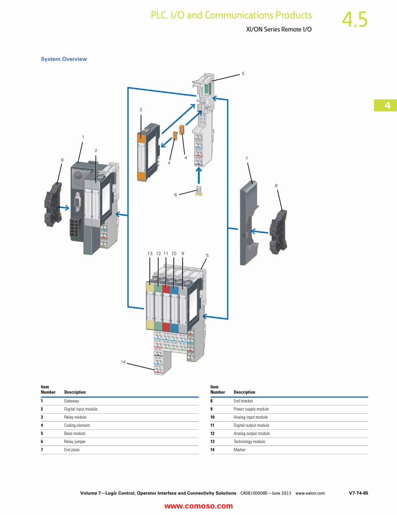
System Overview
ItemNumber Description
ItemNumber Description
1 Gateway 8 End bracket
2 Digital input module 9 Power supply module
3 Relay module 10 Analog input module
4 Coding element 11 Digital output module
5 Base module 12 Analog output module
6 Relay jumper 13 Technology module
7 End plate 14 Marker
1
2
3
4
5
7
8
910111213
14
48
6
5
www.comoso.com
V7-T4-66 Volume 7—Logic Control, Operator Interface and Connectivity Solutions CA08100008E—June 2013 www.eaton.com
4
4
4
4
4
4
4
4
4
4
4
4
4
4
4
4
4
4
4
4
4
4
4
4
4
4
4
4
4
4
4.5 PLC, I/O and Communications Products
XI/ON Series Remote I/O
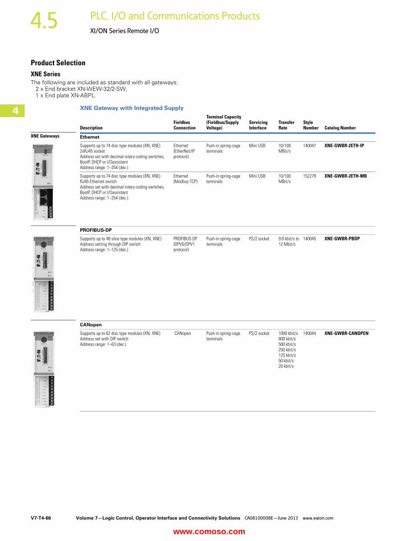
Product SelectionXNE Series The following are included as standard with all gateways: 2 x End bracket XN-WEW-32/2-SW, 1 x End plate XN-ABPL.
XNE Gateway with Integrated Supply
DescriptionFieldbus Connection
Terminal Capacity (Fieldbus/Supply Voltage)
Servicing Interface
Transfer Rate
Style Number Catalog Number
Ethernet
Supports up to 74 disc type modules (XN, XNE) 2xRJ45 socketAddress set with decimal rotary coding switches, BootP, DHCP or I/OassistantAddress range: 1–254 (dec.)
Ethernet (EtherNet/IP protocol)
Push-in spring-cage terminals
Mini USB 10/100 MBit/s
140047 XNE-GWBR-2ETH-IP
Supports up to 74 disc type modules (XN, XNE) RJ45 Ethernet switchAddress set with decimal rotary coding switches, BootP, DHCP or I/OassistantAddress range: 1–254 (dec.)
Ethernet (Modbus TCP)
Push-in spring-cage terminals
Mini USB 10/100 MBit/s
152279 XNE-GWBR-2ETH-MB
PROFIBUS-DP
Supports up to 48 slice type modules (XN, XNE) Address setting through DIP switchAddress range: 1–125 (dec.)
PROFIBUS-DP (DPV0/DPV1 protocol)
Push-in spring-cage terminals
PS/2 socket 9.6 kbit/s to 12 Mbit/s
140045 XNE-GWBR-PBDP
CANopen
Supports up to 62 disc type modules (XN, XNE)Address set with DIP switchAddress range: 1–63 (dec.)
CANopen Push-in spring-cage terminals
PS/2 socket 1000 kbit/s800 kbit/s500 kbit/s250 kbit/s125 kbit/s50 kbit/s20 kbit/s
140044 XNE-GWBR-CANOPEN
XNE Gateways
www.comoso.com

Volume 7—Logic Control, Operator Interface and Connectivity Solutions CA08100008E—June 2013 www.eaton.com V7-T4-67
4
4
4
4
4
4
4
4
4
4
4
4
4
4
4
4
4
4
4
4
4
4
4
4
4
4
4
4
4
4
4.5PLC, I/O and Communications Products
XI/ON Series Remote I/O
XNE Digital Input Modules Positive switching.
XNE Digital Output ModulesResistive inductive and lamp load connectable.
XNE Analog Input and RTD ModuleRated voltage via power supply terminal: 24 Vdc.
XNE Analog Output ModuleRated voltage via power supply terminal: 24 Vdc.
XNE Counter ModuleRated voltage via power supply terminal: 24 Vdc.Signal evaluation A, B: Pulse and direction, rotary encoder single/double/quadruple.
Note1 cUL pending.
ChannelsRated Voltage via Power Supply Terminal
Input Delay tRise/tFall
Input Voltage High Signal
Style Number Catalog Number
8 24 Vdc <100/<200 μs 11 V-UL 140035 XNE-8DI-24VDC-P
16 24 Vdc <150/<300 μs 11 V-UL 140040 XNE-16DI-24VDC-P
ChannelsRated Voltage via Power Supply Terminal
Switching Frequency with Resistive Load in Hz
Utilization Factorg in %
Style Number Catalog Number
8 24 Vdc <100 100 140036 XNE-8DO-24VDC-0.5A-P
16 24 Vdc <100 50%, maximum 4A 140039 XNE-16DO-24VDC-0.5A-P
Channels Measured Variables Measuring Ranges Value Representation
Limit Frequency in Hz
Style Number Catalog Number
8 (U/I)/4 (PT/NI/R)
Voltage, current temperature (PT, NI), resistance R
–10 to 10 Vdc/0 to 10 Vdc PT100, 200, 500, 1000, NI100, 1000 2-, 3-wire
Standard:16-bit/12-bit (flush-left)
1.5 140037 XNE-8AI-U/I-4PT/NI
Extended range:16-bit/12-bit (flush-left) PA (NE43), 16-bit/12-bit (flush-left)
Channels Measured Variables Output Variables Value RepresentationStyle Number Catalog Number
4 Voltage, current –10 to 10 Vdc/0 to 10 Vdc0 to 20 mA4 to 20 mA
Standard:16-bit/12-bit (flush-left)
140034 XNE-4AO-U/I 1
Channels Operating Modes Pulse DurationPWMModule Resolution
Style Number Catalog Number
2 Continuous, once only and periodic counting
32-bit/maximum 120s ✓ 32-bit 140038 XNE-2CNT-2PWM
XNE Digital Input
XNE Digital Output
XNE Analog Input
XNE Analog Output
XNE Counter
www.comoso.com
V7-T4-68 Volume 7—Logic Control, Operator Interface and Connectivity Solutions CA08100008E—June 2013 www.eaton.com
4
4
4
4
4
4
4
4
4
4
4
4
4
4
4
4
4
4
4
4
4
4
4
4
4
4
4
4
4
4
4.5 PLC, I/O and Communications Products
XI/ON Series Remote I/O
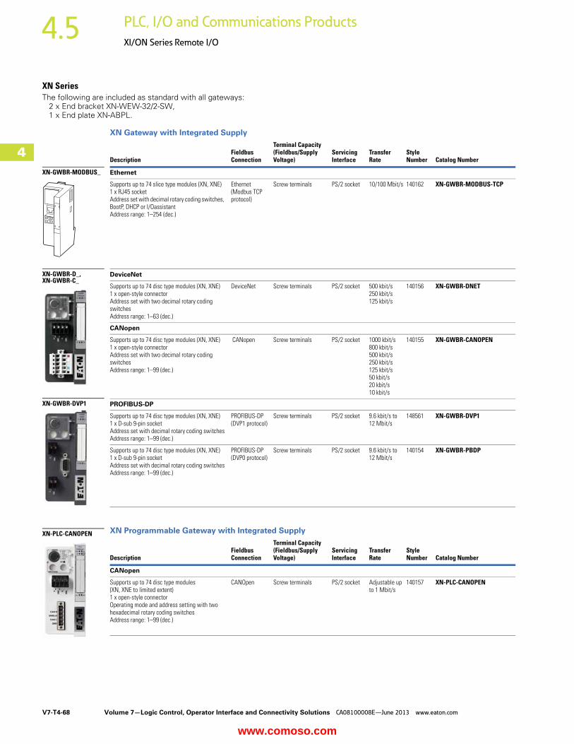
XN SeriesThe following are included as standard with all gateways: 2 x End bracket XN-WEW-32/2-SW, 1 x End plate XN-ABPL.
XN Gateway with Integrated Supply
XN Programmable Gateway with Integrated Supply
DescriptionFieldbus Connection
Terminal Capacity (Fieldbus/Supply Voltage)
Servicing Interface
Transfer Rate
Style Number Catalog Number
Ethernet
Supports up to 74 slice type modules (XN, XNE) 1 x RJ45 socketAddress set with decimal rotary coding switches, BootP, DHCP or I/OassistantAddress range: 1–254 (dec.)
Ethernet (Modbus TCP protocol)
Screw terminals PS/2 socket 10/100 Mbit/s 140162 XN-GWBR-MODBUS-TCP
DeviceNet
Supports up to 74 disc type modules (XN, XNE) 1 x open-style connectorAddress set with two decimal rotary coding switchesAddress range: 1–63 (dec.)
DeviceNet Screw terminals PS/2 socket 500 kbit/s250 kbit/s125 kbit/s
140156 XN-GWBR-DNET
CANopen
Supports up to 74 disc type modules (XN, XNE) 1 x open-style connectorAddress set with two decimal rotary coding switchesAddress range: 1–99 (dec.)
CANopen Screw terminals PS/2 socket 1000 kbit/s800 kbit/s500 kbit/s250 kbit/s125 kbit/s50 kbit/s20 kbit/s10 kbit/s
140155 XN-GWBR-CANOPEN
PROFIBUS-DP
Supports up to 74 disc type modules (XN, XNE) 1 x D-sub 9-pin socketAddress set with decimal rotary coding switchesAddress range: 1–99 (dec.)
PROFIBUS-DP (DVP1 protocol)
Screw terminals PS/2 socket 9.6 kbit/s to 12 Mbit/s
148561 XN-GWBR-DVP1
Supports up to 74 disc type modules (XN, XNE) 1 x D-sub 9-pin socketAddress set with decimal rotary coding switchesAddress range: 1–99 (dec.)
PROFIBUS-DP (DVP0 protocol)
Screw terminals PS/2 socket 9.6 kbit/s to 12 Mbit/s
140154 XN-GWBR-PBDP
DescriptionFieldbus Connection
Terminal Capacity (Fieldbus/Supply Voltage)
Servicing Interface
Transfer Rate
Style Number Catalog Number
CANopen
Supports up to 74 disc type modules (XN, XNE to limited extent) 1 x open-style connectorOperating mode and address setting with two hexadecimal rotary coding switchesAddress range: 1–99 (dec.)
CANOpen Screw terminals PS/2 socket Adjustable up to 1 Mbit/s
140157 XN-PLC-CANOPEN
XN-GWBR-D_,XN-GWBR-C_
XN-GWBR-DVP1
XN-GWBR-MODBUS_
XN-PLC-CANOPEN
www.comoso.com

Volume 7—Logic Control, Operator Interface and Connectivity Solutions CA08100008E—June 2013 www.eaton.com V7-T4-69
4
4
4
4
4
4
4
4
4
4
4
4
4
4
4
4
4
4
4
4
4
4
4
4
4
4
4
4
4
4
4.5PLC, I/O and Communications Products
XI/ON Series Remote I/O
XN Power Supply ModulesNumber of diagnostic bits: 4.Ripple <5% (to EN 61131-2).
XN Digital Input ModulesBase module required.
Operating and Field Voltage
System Power Supply
Rated Current Consumption from Modbus
Maximum System Supply Current
For UseWith …
Style Number Catalog Number
24 Vdc 24 Vdc — 1.5A XN-P3T-SBBXN-P3S-SBBXN-P4T-SBBCXN-P4S-SBBCXN-P3T-SBB-BXN-P3S-SBB-BXN-P4T-SBBC-BXN-P4S-SBBC-B
140071 XN-BR-24VDC-D
24 Vdc — <28 mA — XN-P3T-SBBXN-P3S-SBBXN-P4T-SBBCXN-P4S-SBBC
140070 XN-PF-24VDC-D
120/230 Vac — <25 mA — XN-P3T-SBBXN-P3S-SBBXN-P4T-SBBCXN-P4S-SBBC
140072 XN-PF-120/230VAC-D
Channels
Rated Voltage via Power Supply Terminal
Input DelaytRise/tFall
Input VoltageHigh Signal
For UseWith …
Style Number Catalog Number
2 24 Vdc <200/<200 μs 11–30 Vdc XN-S3T-SBBXN-S3S-SBBXN-S4T-SBBCXN-S4S-SBBC
140056 XN-2DI-24VDC-P
0–5 Vdc 140057 XN-2DI-24VDC-N
2 120/230 Vac <20,000/<20,000 μs 79–265 Vac 140058 XN-2DI-120/230VAC
4 24 Vdc <200/<200 μs 15–30 Vdc XN-S4T-SBBSXN-S4S-SBBSXN-S6T-SBBSBBXN-S6S-SBBSBB
140052 XN-4DI-24VDC-P
0–5 Vdc 140059 XN-4DI-24VDC-N
16 24 Vdc <200/<200 μs 15–30 Vdc XN-B3T-SBBXN-B3S-SBBXN-B4T-SBBCXN-B4S-SBBC
140142 XN-16DI-24VDC-P
32 24 Vdc <200/<200 μs 15–30 Vdc XN-B6T-SBBSBBXN-B6S-SBBSBB
140147 XN-32DI-24VDC-P
Slice Module
Slice Module
Block Module
www.comoso.com

V7-T4-70 Volume 7—Logic Control, Operator Interface and Connectivity Solutions CA08100008E—June 2013 www.eaton.com
4
4
4
4
4
4
4
4
4
4
4
4
4
4
4
4
4
4
4
4
4
4
4
4
4
4
4
4
4
4
4.5 PLC, I/O and Communications Products
XI/ON Series Remote I/O
XN Digital Output ModulesBase module required. Resistive inductive and lamp load connectable.
XN Relay ModulesBase module required. Rated voltage via power supply terminal: 24 Vdc. Resistive inductive and lamp load connectable.
XN Analog Input ModulesBase module required. Rated voltage via power supply terminal: 24 Vdc.
Channels
Rated Voltage via Power Supply Terminal
Switching Frequency with Resistive Load in Hz
Utilization Factor g in %
For UseWith …
Style Number Catalog Number
2 24 Vdc <5000 (RLO <1 kohm) 100 XN-S3T-SBCXN-S3S-SBCXN-S4T-SBCSXN-S4S-SBCS
140053 XN-2DO-24VDC-0.5A-P
<100 (RLO <1 kohm) 140060 XN-2DO-24VDC-0.5A-N
<5000 (RLO <1 kohm) 140055 XN-2DO-24VDC-2A-P
2 120–230 Vac (45–65 Hz)
— 100 (observe derating requirements)
140150 XN-2DO-120/230VAC-0.5A
4 24 Vdc <1000 (RLO <1 kohm) 100 XN-S4T-SBCSXN-S4S-SBCSXN-S6T-SBCSBCXN-S6S-SBCSBC
140148 XN-4DO-24VDC-0.5A-P
16 24 Vdc <100 (RLO <1 kohm) 100 XN-B3T-SBCXN-B3S-SBC
140141 XN-16DO-24VDC-0.5A-P
32 24 Vdc <100 (RLO <1 kohm) See total module current
XN-B6T-SBCSBCXN-B6S-SBCSBC
140161 XN-32DO-24VDC-0.5A-P
Channels Contact TypeRated Load Voltage
Maximum Continuous Current per Channel/230 Vac Resistive Load
For UseWith …
Style Number Catalog Number
2 ChangeoverContacts
230 Vac, 30 Vdc 5A XN-S4T-SBBSXN-S4S-SBBS
140054 XN-2DO-R-CO
2 NC 230 Vac, 30 Vdc 5A XN-S4T-SBBSXN-S4S-SBBSXN-S4T-SBCSXN-S4S-SBCS
140061 XN-2DO-R-NC
NO 140062 XN-2DO-R-NO
ChannelsMeasured Variables
MeasuringRange
ValueRepresentation
Limit Frequency in Hz
For UseWith …
Style Number Catalog Number
1 Current 0–20 mA,4–20 mA
Standard16-bit/12-bit(flush left)
— XN-S3T-SBBXN-S3S-SBBXN-S4T-SBBSXN-S4S-SBBS
140063 XN-1AI-I(0/4…20MA)
2 — 140144 XN-2AI-I(0/4…20MA)
1 Voltage –10…10 Vdc,0…10 Vdc
200 140064 XN-1AI-U(-10/0…+10VDC)
2 50 140145 XN-2AI-U(-10/0…+10VDC)
4 Voltage/Current –10…10 Vdc,0…10 Vdc
20 XN-S6T-SBCSBCXN-S6S-SBCSBC
140158 XN-4AI-U/I
Slice Module
Block Module
Slice Module
Slice Module
www.comoso.com
Volume 7—Logic Control, Operator Interface and Connectivity Solutions CA08100008E—June 2013 www.eaton.com V7-T4-71
4
4
4
4
4
4
4
4
4
4
4
4
4
4
4
4
4
4
4
4
4
4
4
4
4
4
4
4
4
4
4.5PLC, I/O and Communications Products
XI/ON Series Remote I/O
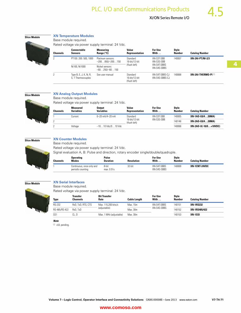
XN Temperature ModulesBase module required. Rated voltage via power supply terminal: 24 Vdc.
XN Analog Output ModulesBase module required. Rated voltage via power supply terminal: 24 Vdc.
XN Counter ModulesBase module required. Rated voltage via power supply terminal: 24 Vdc.Signal evaluation A, B: Pulse and direction, rotary encoder single/double/quadruple.
XN Serial InterfacesBase module required. Rated voltage via power supply terminal: 24 Vdc.
Note1 cUL pending.
ChannelsConnectable Sensors
MeasuringRange (°C)
ValueRepresentation
For UseWith …
Style Number Catalog Number
2 PT100. 200. 500, 1000 Platinum sensors:–200…850/–200…150
Standard16-bit/12-bit(flush left)
XN-S3T-SBBXN-S3S-SBBXN-S4T-SBBSXN-S4S-SBBS
140067 XN-2AI-PT/NI-2/3
Ni100, Ni1000 Nickel sensors:–60…250/–60…150
2 Type B, E, J, K, N, R, S, T Thermocouples
See user manual Standard16-bit/12-bit(flush left)
XN-S4T-SBBS-CJXN-S4S-SBBS-CJ
140068 XN-2AI-THERMO-PI 1
ChannelsMeasured Variables
Output Variables
ValueRepresentation
For UseWith …
Style Number Catalog Number
1 Current 0–20 mA/4–20 mA Standard16-bit/12-bit(flush left)
XN-S3T-SBBXN-S3S-SBB
140065 XN-1AO-I(0/4…20MA)
2 140146 XN-2AO-I(0/4…20MA)
2 Voltage –10…10 Vdc/0…10 Vdc 140066 XN-2AO-U(-10/0…+10VDC)
ChannelsOperating Modes
PulseDuration Resolution
For UseWith …
Style Number Catalog Number
1 Continuous, once only and periodic counting
8-bitmax. 0.51s
32-bit XN-S4T-SBBSXN-S4S-SBBS
140069 XN-1CNT-24VDC
TypeTransfer Channels
Bit Transfer Rate Cable Length
For UseWith …
Style Number Catalog Number
RS-232 RxD, TxD, RTS, CTS Max. 115,200 bits/s(adjustable)
Max. 15m XN-S4T-SBBSXN-S4S-SBBS
140151 XN-1RS232
RS-485/RS-422 RxD, TxD Max. 30m 140152 XN-1RS485/422
SS1 CL, D Max. 1 MHz (adjustable) Max. 30m 140153 XN-1SSI
Slice Module
Slice Module
Slice Module
Slice Module
www.comoso.com
V7-T4-72 Volume 7—Logic Control, Operator Interface and Connectivity Solutions CA08100008E—June 2013 www.eaton.com
4
4
4
4
4
4
4
4
4
4
4
4
4
4
4
4
4
4
4
4
4
4
4
4
4
4
4
4
4
4
4.5 PLC, I/O and Communications Products
XI/ON Series Remote I/O
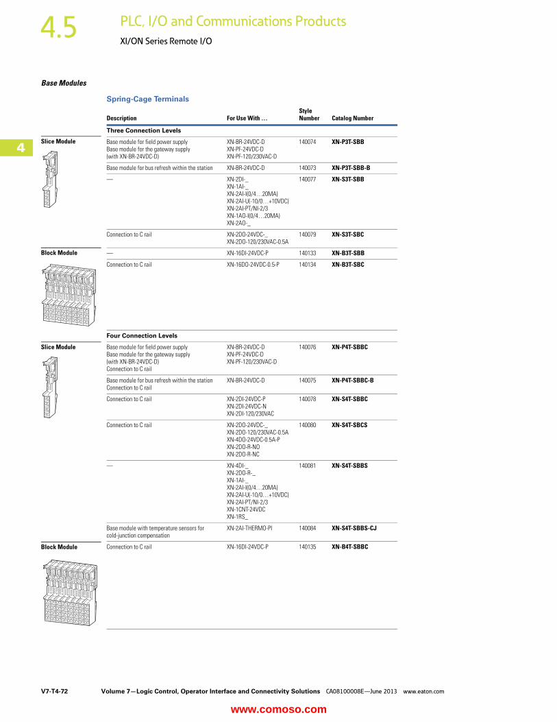
Base Modules
Spring-Cage Terminals
Description For Use With …Style Number Catalog Number
Three Connection Levels
Base module for field power supplyBase module for the gateway supply (with XN-BR-24VDC-D)
XN-BR-24VDC-DXN-PF-24VDC-DXN-PF-120/230VAC-D
140074 XN-P3T-SBB
Base module for bus refresh within the station XN-BR-24VDC-D 140073 XN-P3T-SBB-B
— XN-2DI-_XN-1AI-_XN-2AI-I(0/4…20MA)XN-2AI-U(-10/0…+10VDC)XN-2AI-PT/NI-2/3XN-1AO-I(0/4…20MA)XN-2AO-_
140077 XN-S3T-SBB
Connection to C rail XN-2DO-24VDC-_XN-2DO-120/230VAC-0.5A
140079 XN-S3T-SBC
— XN-16DI-24VDC-P 140133 XN-B3T-SBB
Connection to C rail XN-16DO-24VDC-0.5-P 140134 XN-B3T-SBC
Four Connection Levels
Base module for field power supplyBase module for the gateway supply(with XN-BR-24VDC-D)Connection to C rail
XN-BR-24VDC-DXN-PF-24VDC-DXN-PF-120/230VAC-D
140076 XN-P4T-SBBC
Base module for bus refresh within the stationConnection to C rail
XN-BR-24VDC-D 140075 XN-P4T-SBBC-B
Connection to C rail XN-2DI-24VDC-PXN-2DI-24VDC-NXN-2DI-120/230VAC
140078 XN-S4T-SBBC
Connection to C rail XN-2DO-24VDC-_XN-2DO-120/230VAC-0.5AXN-4DO-24VDC-0.5A-PXN-2DO-R-NOXN-2DO-R-NC
140080 XN-S4T-SBCS
— XN-4DI-_XN-2DO-R-_XN-1AI-_XN-2AI-I(0/4…20MA)XN-2AI-U(-10/0…+10VDC)XN-2AI-PT/NI-2/3XN-1CNT-24VDCXN-1RS_
140081 XN-S4T-SBBS
Base module with temperature sensors for cold-junction compensation
XN-2AI-THERMO-PI 140084 XN-S4T-SBBS-CJ
Connection to C rail XN-16DI-24VDC-P 140135 XN-B4T-SBBC
Slice Module
Block Module
Slice Module
Block Module
www.comoso.com
Volume 7—Logic Control, Operator Interface and Connectivity Solutions CA08100008E—June 2013 www.eaton.com V7-T4-73
4
4
4
4
4
4
4
4
4
4
4
4
4
4
4
4
4
4
4
4
4
4
4
4
4
4
4
4
4
4
4.5PLC, I/O and Communications Products
XI/ON Series Remote I/O
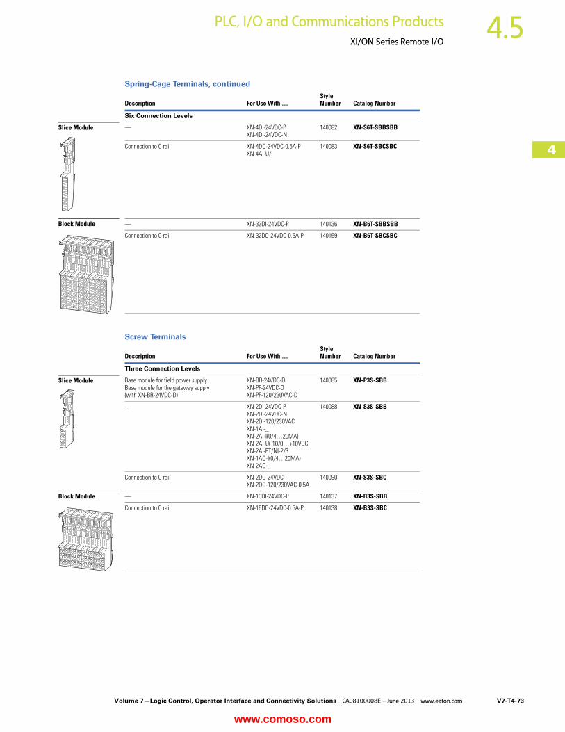
Spring-Cage Terminals, continued
Screw Terminals
Description For Use With …Style Number Catalog Number
Six Connection Levels
— XN-4DI-24VDC-PXN-4DI-24VDC-N
140082 XN-S6T-SBBSBB
Connection to C rail XN-4DO-24VDC-0.5A-PXN-4AI-U/I
140083 XN-S6T-SBCSBC
— XN-32DI-24VDC-P 140136 XN-B6T-SBBSBB
Connection to C rail XN-32DO-24VDC-0.5A-P 140159 XN-B6T-SBCSBC
Description For Use With …Style Number Catalog Number
Three Connection Levels
Base module for field power supplyBase module for the gateway supply (with XN-BR-24VDC-D)
XN-BR-24VDC-DXN-PF-24VDC-DXN-PF-120/230VAC-D
140085 XN-P3S-SBB
— XN-2DI-24VDC-PXN-2DI-24VDC-NXN-2DI-120/230VACXN-1AI-_XN-2AI-I(0/4…20MA)XN-2AI-U(-10/0…+10VDC)XN-2AI-PT/NI-2/3XN-1AO-I(0/4…20MA)XN-2AO-_
140088 XN-S3S-SBB
Connection to C rail XN-2DO-24VDC-_XN-2DO-120/230VAC-0.5A
140090 XN-S3S-SBC
— XN-16DI-24VDC-P 140137 XN-B3S-SBB
Connection to C rail XN-16DO-24VDC-0.5A-P 140138 XN-B3S-SBC
Slice Module
Block Module
Slice Module
Block Module
www.comoso.com

V7-T4-74 Volume 7—Logic Control, Operator Interface and Connectivity Solutions CA08100008E—June 2013 www.eaton.com
4
4
4
4
4
4
4
4
4
4
4
4
4
4
4
4
4
4
4
4
4
4
4
4
4
4
4
4
4
4
4.5 PLC, I/O and Communications Products
XI/ON Series Remote I/O
Screw Terminals, continued
Description For Use With …Style Number Catalog Number
Four Connection Levels
Base module for field power supplyBase module for the gateway supply(with XN-BR-24VDC-D)Connection to C rail
XN-BR-24VDC-DXN-PF-24VDC-DXN-PF-120/230VAC-D
140087 XN-P4S-SBBC
Base module for bus refresh within the stationConnection to C rail
XN-BR-24VDC-D 140086 XN-P4S-SBBC-B
Connection to C rail XN-2DI-24VDC-PXN-2DI-24VDC-NXN-2DI-120/230VAC
140089 XN-S4S-SBBC
Connection to C rail XN-2DO-24VDC-_XN-2DO-120/230VAC-0.5AXN-4DO-24VDC-0.5A-PXN-2DO-R-NOXN-2DO-R-NC
140091 XN-S4S-SBCS
— XN-4DI-_XN-2DO-R-_XN-1AI-_XN-2AI-I(0/4…20MA)XN-2AI-U(-10/0…+10VDC)XN-2AI-PT/NI-2/3XN-1CNT-24VDCXN-1RS_XN-1SSI
140092 XN-S4S-SBBS
Base module with temperature sensors for cold-junction compensation
XN-2AI-THERMO-PI 140095 XN-S4S-SBBS-CJ
Connection to C rail XN-16DI-24VDC-P 140139 XN-B4S-SBBC
Six Connection Levels
— XN-4DI-24VDC-PXN-4DI-24VDC-N
140093 XN-S6S-SBBSBB
Connection to C rail XN-4DO-24VDC-0.5A-PXN-4AI-U/I
140094 XN-S6S-SBCSBC
— XN-32DI-24VDC-P 140140 XN-B6S-SBBSBB
Connection to C rail XN-32DO-24VDC-0.5A-P 140160 XN-B6S-SBCSBC
Slice Module
Block Module
Slice Module
Block Module
www.comoso.com

Volume 7—Logic Control, Operator Interface and Connectivity Solutions CA08100008E—June 2013 www.eaton.com V7-T4-75
4
4
4
4
4
4
4
4
4
4
4
4
4
4
4
4
4
4
4
4
4
4
4
4
4
4
4
4
4
4
4.5PLC, I/O and Communications Products
XI/ON Series Remote I/O
Accessories
Coding Elements
Relay Jumpers
Servicing Cable
End Bracket
End Cover
Connection Level Labels
Labels
Description For Use With …Style Number Catalog Number
Included as standard with every electronics module. Prevents incorrect connection of the electronics modules
XN-…DI-24VDC_ 140114 XN-KO/2
XN-2DI-120/230VAC 140117 XN-KO/5
XN-xDO-24VDC_ 140118 XN-KO/6
XN-2DO-R-NO 140119 XN-KO/8
XN-2DO-R-NC 140120 XN-KO/9
XN-2DO-R-CO 140121 XN-KO/10
XN-1AI-I(0/4…20MA)XN-2AI-I(0/4…20MA)
140122 XN-KO/11
XN-1AI-U(-10/0…+10VDC)XN-2AI-U(-10/0…+10VDC)XN-2AI-PT/NI-2/3XN-2AI-THERMO-PIXN-4AI-U/I
140123 XN-KO/12
XN-1AO-I(0/4…20MA)XN-2AO-I(0/4…20MA)
140124 XN-KO/13
XN-2AO-U(-10/0…+10VDC) 140125 XN-KO/14
XN-1CNT-24VDCXN-1RS232XN-1RS485/422XN-1SSI
140126 XN-KO/15
XN-BR-24VDC-DXN-PF-24VDC-D
140127 XN-KO/16
XN-PF-120/230VAC-D 140128 XN-KO/17
Coding Elements
DescriptionStyle Number
Catalog Number
1-grid 140097 XN-QV/1
2-grid 140098 XN-QV/2
3-grid 140099 XN-QV/3
4-grid 140100 XN-QV/4
5-grid 140101 XN-QV/5
6-grid 140102 XN-QV/6
7-grid 140103 XN-QV/7
8-grid 140104 XN-QV/8
DescriptionStyle Number Catalog Number
Establishes the connection between I/O assistant and the service interface at the gateway
140096 XN-PS2-CABLE
DescriptionStyle Number Catalog Number
For fixing the XI/ON station on the top-hat rail. Two end brackets are supplied as standard with the gateways
140130 XN-WEW-35/2-SW
Relay Jumper
End Bracket
DescriptionStyle Number Catalog Number
For covering an XI/ON station. An end cover is supplied with the gateway as standard
140129 XN-ABPL
DescriptionStyle Number Catalog Number
Blue 140105 XN-ANBZ-BL
Red 140106 XN-ANBZ-RT
Green 140107 XN-ANBZ-GN
Black 140108 XN-ANBZ-SW
Brown 140109 XN-ANBZ-BR
Red/blue 140110 XN-ANBZ-RT/BL-BED
Yellow/green 140111 XN-ANBZ-GN/GE-BED
White 140112 XN-ANBZ-WS
DescriptionStyle Number Catalog Number
A5 sheet, perforated, 1 x 57 labels 140131 XN-LABEL/SCHEIBE
A5 sheet, perforated, 1 x 6 labels 140132 XN-LABEL/BLOCK
End Cover
Connection Level Labels
www.comoso.com

V7-T4-76 Volume 7—Logic Control, Operator Interface and Connectivity Solutions CA08100008E—June 2013 www.eaton.com
4
4
4
4
4
4
4
4
4
4
4
4
4
4
4
4
4
4
4
4
4
4
4
4
4
4
4
4
4
4
4.5 PLC, I/O and Communications Products
XI/ON Series Remote I/O
Technical Data and Specifications
XI/ON General
Terminals
Description Unit Specification
Standards EN 61000-6-2, EN 61000-6-4, EN 61131-2
Supported fieldbus systems PROFIBUS-DP, CANopen, DeviceNet, Modbus TCP, EtherNet/IP (depending on gateway)
Potential isolation Yes, through optocoupler
Ambient temperature °F (°C) 32° to 131° (0° to 55°)
Ambient temperature, storage °F (°C) –13° to 185° (–25° to 85°)
Relative humidity % 5–95 (indoor), Level RH-2, non-condensing (for storage at 45°C)
Harmful gases
SO2 ppm 10 (relative humidity <75%, non-condensing)
H2S ppm 1.0 (relative humidity <75%, non-condensing)
Vibration resistance, operating conditions According to IEC 60068-2-6
Mechanical shock resistance According to IEC 60068-2-27
Repetitive shock resistance According to IEC 60068-2-29
Drop and free fall According to IEC 60068-2-31, free fall to IEC 60068-2-32
Protection type IP20
Electromagnetic compatibility (EMC)
ESD EN 61000-4-2
Electromagnetic fields EN 61000-4-3
Burst EN 61000-4-4
Surge EN 61000-4-5
HF, asymmetric EN 61000-4-6
Radiated interference (RFI) EN 55016-2-3
Voltage fluctuations EN 61131-2
Type test To EN 61131-2
Approvals CE, cUL
Description UnitXN Gateways andXN Basic Modules
XNE Gateways and Integrated XNE Modules
Dimensional data To VDE 0611 Part 1/8.92/IEC/EN 60947-7-1
To VDE 0611 Part 1/8.92/IEC/EN 60947-7-1
Connection from above Spring-loaded/screw terminals Push-in spring-cage terminals
Cable stripped length mm 8 8
Max. terminal capacity mm2 0.5–2.5 0.14–1.5
Connectable conductors
“e” solid H07V-U mm2 0.5–2.5 0.25–1.5
“f” flexible H 07V-K mm2 0.5–1.5 0.25–1.5
“f” with ferrule without plastic collar to DIN 46228-1 (ferrules gas-tight)
mm2 0.5–1.5 0.25–1.5
“f” with ferrule with plastic collar to DIN 46228-1 (ferrules gas-tight)
mm2 0.5–1.5 0.25–0.75
Gauge pin IEC/EN 60947-1 A1 A1
www.comoso.com
Volume 7—Logic Control, Operator Interface and Connectivity Solutions CA08100008E—June 2013 www.eaton.com V7-T4-77
4
4
4
4
4
4
4
4
4
4
4
4
4
4
4
4
4
4
4
4
4
4
4
4
4
4
4
4
4
4
4.5PLC, I/O and Communications Products
XI/ON Series Remote I/O
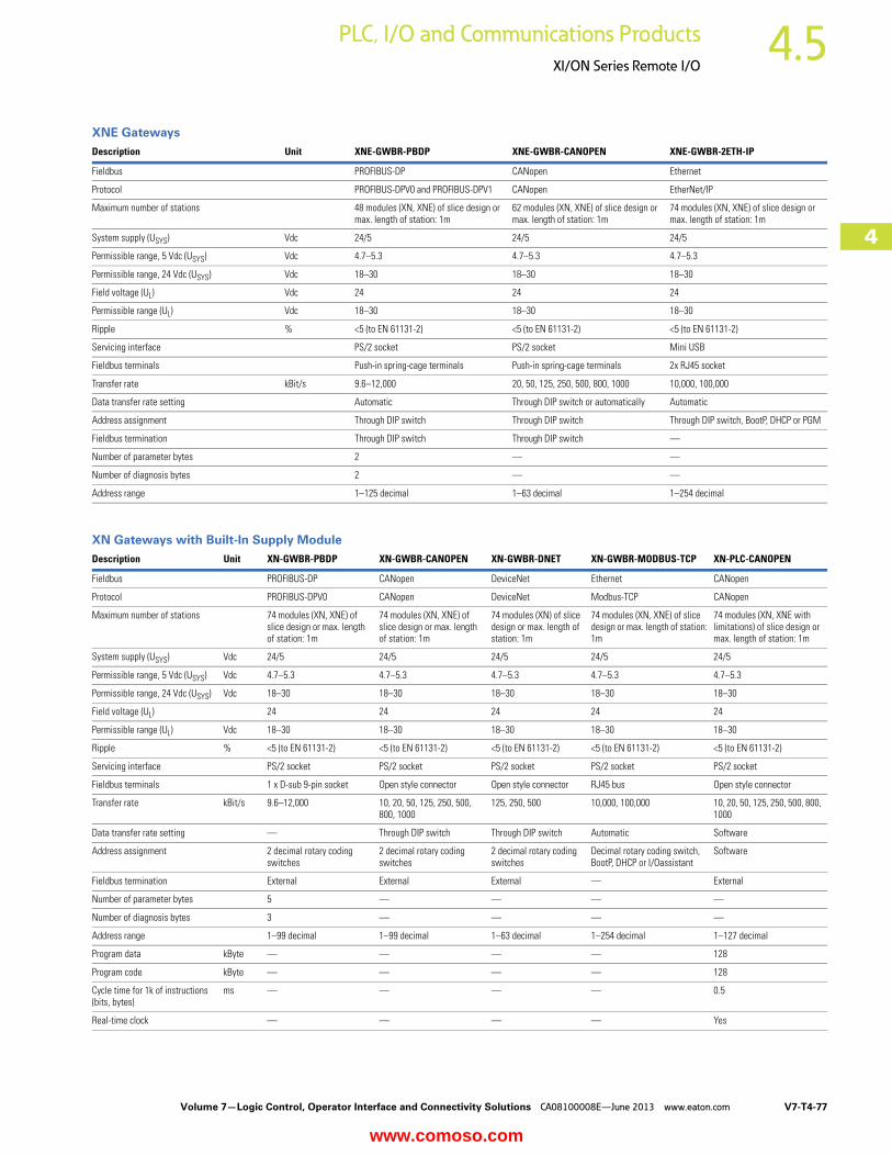
XNE Gateways
XN Gateways with Built-In Supply Module
Description Unit XNE-GWBR-PBDP XNE-GWBR-CANOPEN XNE-GWBR-2ETH-IP
Fieldbus PROFIBUS-DP CANopen Ethernet
Protocol PROFIBUS-DPV0 and PROFIBUS-DPV1 CANopen EtherNet/IP
Maximum number of stations 48 modules (XN, XNE) of slice design or max. length of station: 1m
62 modules (XN, XNE) of slice design or max. length of station: 1m
74 modules (XN, XNE) of slice design or max. length of station: 1m
System supply (USYS) Vdc 24/5 24/5 24/5
Permissible range, 5 Vdc (USYS) Vdc 4.7–5.3 4.7–5.3 4.7–5.3
Permissible range, 24 Vdc (USYS) Vdc 18–30 18–30 18–30
Field voltage (UL) Vdc 24 24 24
Permissible range (UL) Vdc 18–30 18–30 18–30
Ripple % <5 (to EN 61131-2) <5 (to EN 61131-2) <5 (to EN 61131-2)
Servicing interface PS/2 socket PS/2 socket Mini USB
Fieldbus terminals Push-in spring-cage terminals Push-in spring-cage terminals 2x RJ45 socket
Transfer rate kBit/s 9.6–12,000 20, 50, 125, 250, 500, 800, 1000 10,000, 100,000
Data transfer rate setting Automatic Through DIP switch or automatically Automatic
Address assignment Through DIP switch Through DIP switch Through DIP switch, BootP, DHCP or PGM
Fieldbus termination Through DIP switch Through DIP switch —
Number of parameter bytes 2 — —
Number of diagnosis bytes 2 — —
Address range 1–125 decimal 1–63 decimal 1–254 decimal
Description Unit XN-GWBR-PBDP XN-GWBR-CANOPEN XN-GWBR-DNET XN-GWBR-MODBUS-TCP XN-PLC-CANOPEN
Fieldbus PROFIBUS-DP CANopen DeviceNet Ethernet CANopen
Protocol PROFIBUS-DPV0 CANopen DeviceNet Modbus-TCP CANopen
Maximum number of stations 74 modules (XN, XNE) of slice design or max. length of station: 1m
74 modules (XN, XNE) of slice design or max. length of station: 1m
74 modules (XN) of slice design or max. length of station: 1m
74 modules (XN, XNE) of slice design or max. length of station: 1m
74 modules (XN, XNE with limitations) of slice design or max. length of station: 1m
System supply (USYS) Vdc 24/5 24/5 24/5 24/5 24/5
Permissible range, 5 Vdc (USYS) Vdc 4.7–5.3 4.7–5.3 4.7–5.3 4.7–5.3 4.7–5.3
Permissible range, 24 Vdc (USYS) Vdc 18–30 18–30 18–30 18–30 18–30
Field voltage (UL) 24 24 24 24 24
Permissible range (UL) Vdc 18–30 18–30 18–30 18–30 18–30
Ripple % <5 (to EN 61131-2) <5 (to EN 61131-2) <5 (to EN 61131-2) <5 (to EN 61131-2) <5 (to EN 61131-2)
Servicing interface PS/2 socket PS/2 socket PS/2 socket PS/2 socket PS/2 socket
Fieldbus terminals 1 x D-sub 9-pin socket Open style connector Open style connector RJ45 bus Open style connector
Transfer rate kBit/s 9.6–12,000 10, 20, 50, 125, 250, 500, 800, 1000
125, 250, 500 10,000, 100,000 10, 20, 50, 125, 250, 500, 800, 1000
Data transfer rate setting — Through DIP switch Through DIP switch Automatic Software
Address assignment 2 decimal rotary coding switches
2 decimal rotary coding switches
2 decimal rotary coding switches
Decimal rotary coding switch, BootP, DHCP or I/Oassistant
Software
Fieldbus termination External External External — External
Number of parameter bytes 5 — — — —
Number of diagnosis bytes 3 — — — —
Address range 1–99 decimal 1–99 decimal 1–63 decimal 1–254 decimal 1–127 decimal
Program data kByte — — — — 128
Program code kByte — — — — 128
Cycle time for 1k of instructions (bits, bytes)
ms — — — — 0.5
Real-time clock — — — — Yes
www.comoso.com

V7-T4-78 Volume 7—Logic Control, Operator Interface and Connectivity Solutions CA08100008E—June 2013 www.eaton.com
4
4
4
4
4
4
4
4
4
4
4
4
4
4
4
4
4
4
4
4
4
4
4
4
4
4
4
4
4
4
4.5 PLC, I/O and Communications Products
XI/ON Series Remote I/O
Supply Modules
Digital Input Modules
Notes1 Permissible range for system supply: for USYS = 24 Vdc: 18 to 30 Vdc (to EN 61131-2).2 Permissible range for field voltage UL: to EN 61131-2 (18 to 30 Vdc).3 Permissible range for rated voltage and field voltage UL: to EN 61131-2.4 The supply terminal (UL) provides power for the module electronics and for the sensors at the inputs. The total current required for each module consists of the sum of all partial currents.5 Part of the XI/ON module’s electronics is supplied with module bus voltage (5 Vdc), the other part through the supply terminal (UL).6 Maximum permissible capacity: 141 nF at 79 Vac/50 Hz; 23 nF at 265 Vac/50 Hz.
Description Unit XN-BR-24VDC-D XN-PF-24VDC-D XN-PF-120/230VAC-D
Operating voltage 24 Vdc 24 Vdc 120/230 Vac
System supply (USYS) Vdc 24 — —
Permissible range, 24 Vdc (USYS) Vdc 18–30 1 — —
Permissible range, 5 Vdc (UMB [built into system]) Vdc 4.7–5.3 — —
Field voltage (UL) 24 Vdc 24 Vdc 120/230 Vac
Permissible range (UL) 18–30 Vdc 18–30 Vdc 2 102–132 Vac (120 Vac) 195.5–253 Vac (230 Vac) 3
Rated current drawn from module bus (IMB) mA — <28 <25
Insulation test (Ui) Vac 500 500 1500
Ripple % <5 (to EN 61131-2) <5 (to EN 61131-2) <5 (to EN 61131-2)
Maximum operating current (IL) A 10 10 10
Maximum system supply current (IMB) A 1.5 — —
Number of diagnostic bits 4 4 4
Base module without gateway power supply
Without C connection XN-P3…-SBB/XN-P3…-SBB-B XN-P3…-SBB XN-P3…-SBB
With C connection XN-P4…-SBBC/XN-P4…-SBBC-B XN-P4…-SBBC XN-P4…-SBBC
Description Unit XN-2DI-24VDC-P XN-2DI-24VDC-N XN-2DI-120/230VAC XN-4DI-24VDC-P XN-4DI-24VDC-N
Channels Number 2 2 2 4 4
Rated voltage at supply terminal (UL)
24 Vdc 24 Vdc 120/230 Vac 24 Vdc 24 Vdc
Rated current drawn from supply terminal (IL) 45
mA <20 <20 <20 <40 <40
Rated current drawn from module bus (IMB) 5
mA <28 <28 <28 <29 <28
Insulation test (Ui) Vac 500 500 1500 500 500
Heat dissipation W 0.7 0.7 1 1 1
Input voltageInput voltage, rated value 24 Vdc 24 Vdc 120/230 Vac 24 Vdc 24 Vdc
Low level –30V to 5V 30V (UL–11V) 0–20 Vac –30V to 5V 30V (UL–11V)
High level 11–30V 0–5V 79 Vac–265 Vac 6 15 V–30V 0–5V
Frequency range Hz — — 48–63 — —
Input currentLow level/active level 0 mA–1.5 mA 0 mA–1.7 mA 0 mA–1 mA 0 mA–1.5 mA 0 mA–1.2 mA
High level/active level 2 mA–10 mA 1.8 mA–10 mA 3 mA–10 mA 2 mA–10 mA 1.3 mA–6 mA
Input delaytrising edge μs <200 <200 <20,000 <200 <200
tfalling edge μs <200 <200 <20,000 <200 <200
Basic modulesWithout C connection XN-S3…-SBB 2-conductor proximity switches (Bero®)
can be connected, with a permissible quiescent current of up to 1.5 mA
XN-S3…-SBB XN-S4…-SBBS XN-S6…-SBBSBB
XN-S4…-SBBS XN-S6…-SBBSBB
With C connection XN-S4…-SBBC XN-S4…-SBBC XN-S4…-SBBC — —
www.comoso.com

Volume 7—Logic Control, Operator Interface and Connectivity Solutions CA08100008E—June 2013 www.eaton.com V7-T4-79
4
4
4
4
4
4
4
4
4
4
4
4
4
4
4
4
4
4
4
4
4
4
4
4
4
4
4
4
4
4
4.5PLC, I/O and Communications Products
XI/ON Series Remote I/O
Digital Input Modules, continued
Notes1 The supply terminal (UL) provides power for the module electronics and for the sensors at the inputs. The total current required for each module consists of the sum of all partial currents.2 Part of the XI/ON module’s electronics is supplied with module bus voltage (5 Vdc), the other part through the supply terminal (UL).
Description Unit XN-16DI-24VDC-P XN-32DI-24VDC-P XNE-8DI-24VDC-P XNE-16DI-24VDC-P
Channels Number 16 32 8 16
Rated voltage at supply terminal (UL) Vdc 24 24 24 24
Rated current drawn from supply terminal (IL) 12 mA <40 <30 <1.5 <3
Rated current drawn from module bus (IMB) 2 mA <45 <30 <15 <15
Insulation test (Ui) Vac 500 500 500 500
Heat dissipation W 2.5 4.2 <1.5 <2.5
Input voltageInput voltage, rated value Vdc 24 24 24 24
Low level –30V to 5V –30V to 5V –ULto 5V –UL to 5V
High level 15V–30V 15V–30V 11V–UL 11V–UL
Frequency range Hz — — — —
Input currentLow level/active level 0 mA–1.5 mA 0 mA–1.5 mA –1 mA–1.5 mA –1 mA–1.5 mA
High level/active level 2 mA–10 mA 2 mA–10 mA 2 mA–5 mA 2 mA–5 mA
Input delaytrising edge μs <200 <200 <100 <150
tfalling edge μs <200 <200 <200 <300
Basic modulesWithout C connection XN-B3…-SBB XN-B6…-SBBSBB Already built in Already built in
With C connection XN-B4…-SBBC — — —
www.comoso.com

V7-T4-80 Volume 7—Logic Control, Operator Interface and Connectivity Solutions CA08100008E—June 2013 www.eaton.com
4
4
4
4
4
4
4
4
4
4
4
4
4
4
4
4
4
4
4
4
4
4
4
4
4
4
4
4
4
4
4.5 PLC, I/O and Communications Products
XI/ON Series Remote I/O
Digital Output Modules
Notes1 The supply terminal (UL) provides power for the module electronics and for the consumers at the outputs. The total current required for each module consists of the sum of all partial currents.2 Part of the XI/ON module’s electronics is supplied with module bus voltage (5 Vdc), the other part through the supply terminal (UL).3 To increase the maximum output current to up to 1A, two outputs can be connected in parallel.
Description Unit XN-2DO-24VDC-0.5A-P XN-2DO-24VDC-0.5A-N XN-2DO-120/230VAC-0.5A XN-2DO-24VDC-2A-P XN-4DO-24VDC-0.5A-P
Channels Number 2 2 2 2 4
Rated voltage at supply terminal (UL) 24 Vdc 24 Vdc 120/230 Vac (45–65 Hz) 24 Vdc 24 Vdc
Rated current drawn from supply terminal (for 0 mA load current) (IL) 1
mA <20 <20 <20 <50 <25
Rated current drawn from module bus (IMB) 2
mA <32 <32 <35 <33 <30
Insulation test (Ui) Vac 500 500 1500 500 500
Heat dissipation W Normally 1 Normally 1 Normally 1 Normally 1 Normally 1
Output voltageHigh level >UL–1 Vdc <GNDL +1 Vdc >UL–2 Vac,
(zero-point switching triac)>UL–1 Vdc >UL–1 Vdc
Output currentHigh level (rated) A 0.5 0.5 0.5 3 2 0.5
High level (permissible range) A <0.6 <0.6 0.02–0.5 <2.4 <0.6
Low level mA — — <1.5 — —
Back-up fuse — — 500 mA FF — —
Surge current (IS) A — — 8 (1 period at 60 Hz) — —
Number of parallel-switchable outputs (maximum)
— — — — 4
Total module current A 1 1 1 4 2
Delay for signal changeover, resistive loadFrom Low to High level μs <100 <100 <T/2 +1 ms <100 <250
From High to Low level μs <100 <100 <T/2 +1 ms <100 <250
Load resistance range >48 ohm >48 ohm At 120 Vac: 240 ohm to 6 kohm At 230 Vac: 460 ohm to 11.5 kohm
<12 ohm >48 ohm
Utilization factor (%) g 100 100 100 (observe derating) 100 100
The following can be connected: Resistive loads/Inductive loads/Lamp loads
Resistive load ohm >48 >48 — >12 >48
Inductive load H <1.2 <1.2 — <1.2 <1.2
Lamp load (RLL) W <3 <12 — <6 <6
Switching frequencyFor resistive load (f) Hz <5000 (RLO <1 kohm) <100 (RLO <1 kohm) — <5000 (RLO <1 kohm) <1000 (RLO <1 kohm)
For inductive load Hz <2 <2 — <2 <2
For lamps Hz <10 <10 — <10 <10
Number of diagnostic bits 2 2 — 2 1
Diagnostics Yes Yes No Yes Yes
Outputs to EN 61131-1 Protected Protected — Protected Short-circuit proof
Retriggering after elimination of short circuit (Ii)
Self-acting Self-acting — Self-acting Self-acting
Basic modulesWith C connection XN-S3…-SBC
XN-S4…-SBCSXN-S3…-SBCXN-S4…-SBCS
XN-S3…-SBCXN-S4…-SBCS
XN-S3…-SBCXN-S4…-SBCS
XN-S4…-SBCSXN-S4…-SBCSBC
www.comoso.com
Volume 7—Logic Control, Operator Interface and Connectivity Solutions CA08100008E—June 2013 www.eaton.com V7-T4-81
4
4
4
4
4
4
4
4
4
4
4
4
4
4
4
4
4
4
4
4
4
4
4
4
4
4
4
4
4
4
4.5PLC, I/O and Communications Products
XI/ON Series Remote I/O
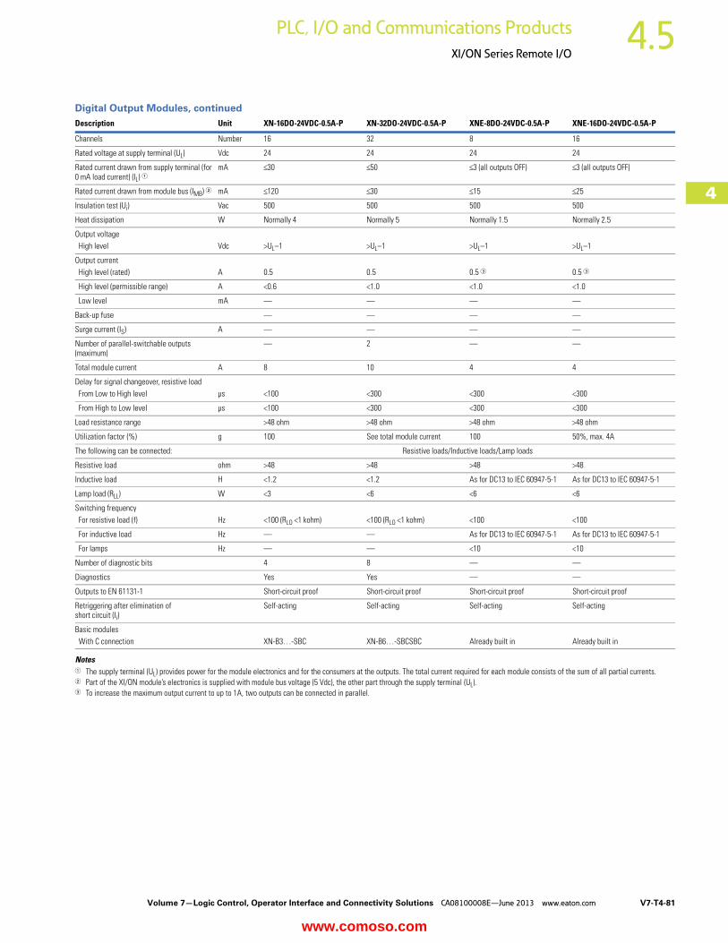
Digital Output Modules, continued
Notes1 The supply terminal (UL) provides power for the module electronics and for the consumers at the outputs. The total current required for each module consists of the sum of all partial currents.2 Part of the XI/ON module’s electronics is supplied with module bus voltage (5 Vdc), the other part through the supply terminal (UL).3 To increase the maximum output current to up to 1A, two outputs can be connected in parallel.
Description Unit XN-16DO-24VDC-0.5A-P XN-32DO-24VDC-0.5A-P XNE-8DO-24VDC-0.5A-P XNE-16DO-24VDC-0.5A-P
Channels Number 16 32 8 16
Rated voltage at supply terminal (UL) Vdc 24 24 24 24
Rated current drawn from supply terminal (for 0 mA load current) (IL) 1
mA <30 <50 <3 (all outputs OFF) <3 (all outputs OFF)
Rated current drawn from module bus (IMB) 2 mA <120 <30 <15 <25
Insulation test (Ui) Vac 500 500 500 500
Heat dissipation W Normally 4 Normally 5 Normally 1.5 Normally 2.5
Output voltageHigh level Vdc >UL–1 >UL–1 >UL–1 >UL–1
Output currentHigh level (rated) A 0.5 0.5 0.5 3 0.5 3
High level (permissible range) A <0.6 <1.0 <1.0 <1.0
Low level mA — — — —
Back-up fuse — — — —
Surge current (IS) A — — — —
Number of parallel-switchable outputs (maximum)
— 2 — —
Total module current A 8 10 4 4
Delay for signal changeover, resistive loadFrom Low to High level μs <100 <300 <300 <300
From High to Low level μs <100 <300 <300 <300
Load resistance range >48 ohm >48 ohm >48 ohm >48 ohm
Utilization factor (%) g 100 See total module current 100 50%, max. 4A
The following can be connected: Resistive loads/Inductive loads/Lamp loads
Resistive load ohm >48 >48 >48 >48
Inductive load H <1.2 <1.2 As for DC13 to IEC 60947-5-1 As for DC13 to IEC 60947-5-1
Lamp load (RLL) W <3 <6 <6 <6
Switching frequencyFor resistive load (f) Hz <100 (RLO <1 kohm) <100 (RLO <1 kohm) <100 <100
For inductive load Hz — — As for DC13 to IEC 60947-5-1 As for DC13 to IEC 60947-5-1
For lamps Hz — — <10 <10
Number of diagnostic bits 4 8 — —
Diagnostics Yes Yes — —
Outputs to EN 61131-1 Short-circuit proof Short-circuit proof Short-circuit proof Short-circuit proof
Retriggering after elimination of short circuit (Ii)
Self-acting Self-acting Self-acting Self-acting
Basic modulesWith C connection XN-B3…-SBC XN-B6…-SBCSBC Already built in Already built in
www.comoso.com

V7-T4-82 Volume 7—Logic Control, Operator Interface and Connectivity Solutions CA08100008E—June 2013 www.eaton.com
4
4
4
4
4
4
4
4
4
4
4
4
4
4
4
4
4
4
4
4
4
4
4
4
4
4
4
4
4
4
4.5 PLC, I/O and Communications Products
XI/ON Series Remote I/O
Analog Input Modules
Notes1 The supply terminal (UL) provides power for the module electronics and for the analog transmitters at the inputs. The total current required for each module consists of the sum of all partial currents.2 Part of the XI/ON module’s electronics is supplied with module bus voltage (5 Vdc), the other part through the supply terminal (UL).
Description Unit XN-1AI-I(0/4…20MA) XN-2AI-I(0/4…20MA) XN-1AI-U(-10/0…+10VDC) XN-2AI-U(-10/0…+10VDC)
Measured variables Current Current Voltage Voltage
Channels Number 1 2 1 2
Rated voltage at supply terminal (UL) Vdc 24 24 24 24
Rated current drawn from supply terminal (IL) 12
mA <50 <12 <50 <12
Rated current drawn from module bus (IMB) 2
mA <41 <35 <41 <35
Heat dissipation W <1 <1 <1 <1
Sensor/transmitter supply Bridged with UL and GNDL of incoming unit; not protected
<250 mA; bridged with UL and GNDL of incoming unit; not protected
Bridged with UL and GNDL of incoming unit; not protected
<250 mA; bridged with UL and GNDL of incoming unit; not protected
Voltage measurementMeasurement ranges — — –10 to 10 Vdc/0 to 10 Vdc –10 to 10 Vdc/0 to 10 Vdc
Value representation — — Standard, 16-bit/12-bit left-aligned
Standard, 16-bit/12-bit left-aligned
The following can be connected: — — 2-/3-/4-conductor + shield 2-/3-conductor + shield
Maximum input voltage (Umax.) Vdc — — 35 35
Input resistance (RL) kohm — — >98.5 >98.5
Limiting frequency (fG) Hz — — 200 50
Basic error limit at 23°C % — — <0.2 <0.2
Temperature coefficient — — <300 ppm/°C of full-scale value <150 ppm/°C of full-scale value
Current measurementMeasurement ranges mA 0–20/4–20 0–20/4–20 — —
Value representation Standard, 16-bit/12-bit (left-aligned)
Standard, 16-bit/12-bit (left-aligned)
— —
The following can be connected: 2-/3-/4-conductor + shield 2-/3-conductor + shield — —
Maximum input current (Imax.) mA 50 50 — —
Input resistance (RL) ohm <125 ohm <125 ohm — —
Limiting frequency (fG) Hz 200 50 — —
Basic error limit at 23°C % <0.2 <0.2 — —
Temperature coefficient <300 ppm/°C of full-scale value <300 ppm/°C of full-scale value — —
Temperature measurementConnectable sensors — — — —
Measurement ranges — — — —
Value representation — — — —
The following can be connected: — — — —
Measuring current (Imess) — — — —
Destruction limit (Umax.) Vdc — — — —
Basic error limit at 23°C % — — — —
Temperature coefficient — — — —
R (resistance measurement)Measurement ranges — — — —
Value representation — — — —
The following can be connected: — — — —
Destruction limit (Umax.) Vdc — — — —
Limiting frequency (fG) Hz — — — —
Basic error limit at 23°C % — — — —
Temperature coefficient — — — —
Basic modulesWithout C connection XN-S3…-SBB XN-S3…-SBB XN-S3…-SBB XN-S3…-SBB
Without C connection, for sensor supply XN-S4…-SBBS XN-S4…-SBBS XN-S4…-SBBS XN-S4…-SBBS
www.comoso.com
Volume 7—Logic Control, Operator Interface and Connectivity Solutions CA08100008E—June 2013 www.eaton.com V7-T4-83
4
4
4
4
4
4
4
4
4
4
4
4
4
4
4
4
4
4
4
4
4
4
4
4
4
4
4
4
4
4
4.5PLC, I/O and Communications Products
XI/ON Series Remote I/O
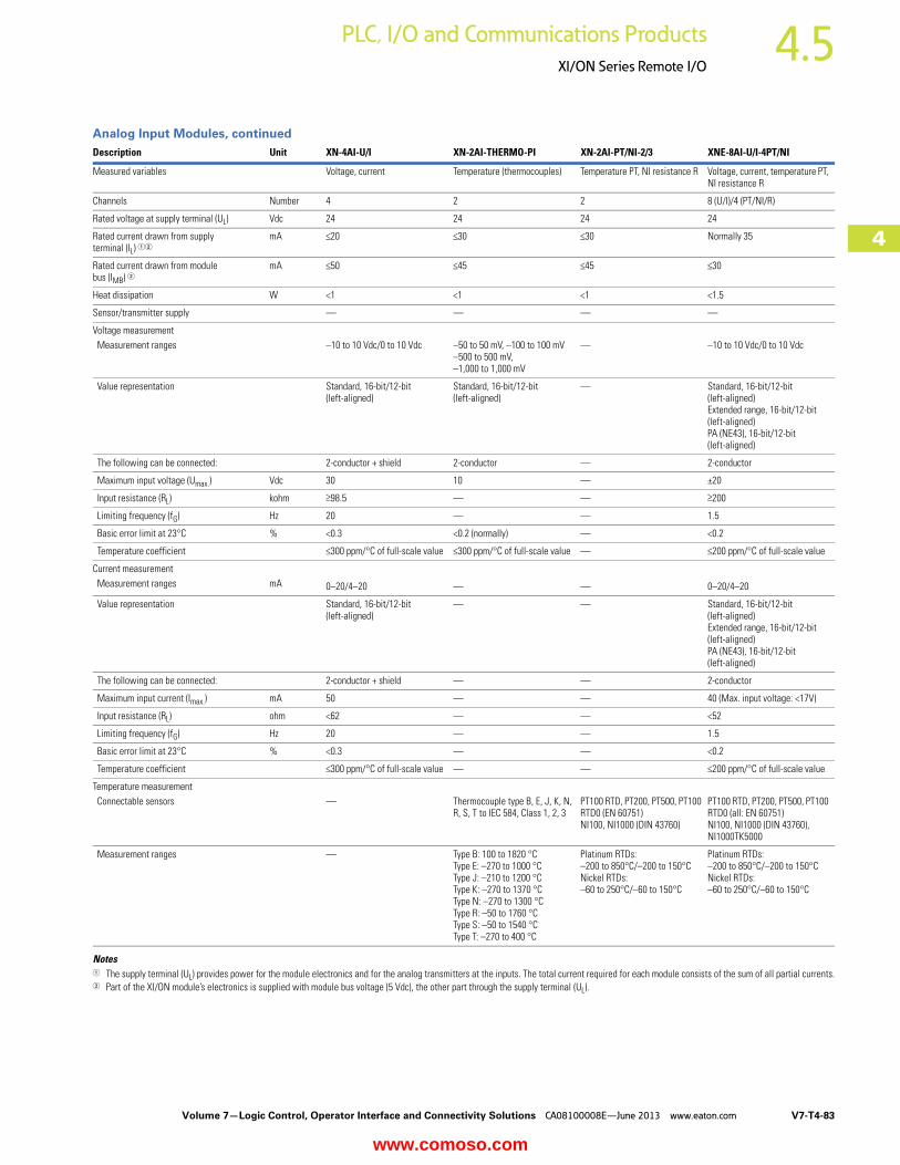
Analog Input Modules, continued
Notes1 The supply terminal (UL) provides power for the module electronics and for the analog transmitters at the inputs. The total current required for each module consists of the sum of all partial currents.2 Part of the XI/ON module’s electronics is supplied with module bus voltage (5 Vdc), the other part through the supply terminal (UL).
Description Unit XN-4AI-U/I XN-2AI-THERMO-PI XN-2AI-PT/NI-2/3 XNE-8AI-U/I-4PT/NI
Measured variables Voltage, current Temperature (thermocouples) Temperature PT, NI resistance R Voltage, current, temperature PT, NI resistance R
Channels Number 4 2 2 8 (U/I)/4 (PT/NI/R)
Rated voltage at supply terminal (UL) Vdc 24 24 24 24
Rated current drawn from supply terminal (IL) 12
mA <20 <30 <30 Normally 35
Rated current drawn from module bus (IMB) 2
mA <50 <45 <45 <30
Heat dissipation W <1 <1 <1 <1.5
Sensor/transmitter supply — — — —
Voltage measurementMeasurement ranges –10 to 10 Vdc/0 to 10 Vdc –50 to 50 mV, –100 to 100 mV
–500 to 500 mV, –1,000 to 1,000 mV
— –10 to 10 Vdc/0 to 10 Vdc
Value representation Standard, 16-bit/12-bit (left-aligned)
Standard, 16-bit/12-bit (left-aligned)
— Standard, 16-bit/12-bit(left-aligned) Extended range, 16-bit/12-bit (left-aligned) PA (NE43), 16-bit/12-bit(left-aligned)
The following can be connected: 2-conductor + shield 2-conductor — 2-conductor
Maximum input voltage (Umax.) Vdc 30 10 — ±20
Input resistance (RL) kohm >98.5 — — >200
Limiting frequency (fG) Hz 20 — — 1.5
Basic error limit at 23°C % <0.3 <0.2 (normally) — <0.2
Temperature coefficient <300 ppm/°C of full-scale value <300 ppm/°C of full-scale value — <200 ppm/°C of full-scale value
Current measurementMeasurement ranges mA 0–20/4–20 — — 0–20/4–20
Value representation Standard, 16-bit/12-bit(left-aligned)
— — Standard, 16-bit/12-bit(left-aligned) Extended range, 16-bit/12-bit (left-aligned) PA (NE43), 16-bit/12-bit (left-aligned)
The following can be connected: 2-conductor + shield — — 2-conductor
Maximum input current (Imax.) mA 50 — — 40 (Max. input voltage: <17V)
Input resistance (RL) ohm <62 — — <52
Limiting frequency (fG) Hz 20 — — 1.5
Basic error limit at 23°C % <0.3 — — <0.2
Temperature coefficient <300 ppm/°C of full-scale value — — <200 ppm/°C of full-scale value
Temperature measurementConnectable sensors — Thermocouple type B, E, J, K, N,
R, S, T to IEC 584, Class 1, 2, 3PT100 RTD, PT200, PT500, PT100 RTD0 (EN 60751) NI100, NI1000 (DIN 43760)
PT100 RTD, PT200, PT500, PT100 RTD0 (all: EN 60751)NI100, NI1000 (DIN 43760), NI1000TK5000
Measurement ranges — Type B: 100 to 1820 °CType E: –270 to 1000 °CType J: –210 to 1200 °CType K: –270 to 1370 °CType N: –270 to 1300 °CType R: –50 to 1760 °CType S: –50 to 1540 °CType T: –270 to 400 °C
Platinum RTDs:–200 to 850°C/–200 to 150°CNickel RTDs:–60 to 250°C/–60 to 150°C
Platinum RTDs:–200 to 850°C/–200 to 150°CNickel RTDs:–60 to 250°C/–60 to 150°C
www.comoso.com

V7-T4-84 Volume 7—Logic Control, Operator Interface and Connectivity Solutions CA08100008E—June 2013 www.eaton.com
4
4
4
4
4
4
4
4
4
4
4
4
4
4
4
4
4
4
4
4
4
4
4
4
4
4
4
4
4
4
4.5 PLC, I/O and Communications Products
XI/ON Series Remote I/O
Analog Input Modules, continued Description Unit XN-4AI-U/I XN-2AI-THERMO-PI XN-2AI-PT/NI-2/3 XNE-8AI-U/I-4PT/NI
Temperature measurement, continuedValue representation — Standard, 16-bit/12-bit left-aligned
The following can be connected: — 2-conductor (cold-junction compensation in base module)
2-conductor/3-conductor 2-conductor/3-conductor
Measuring current (Imess) — — <1 mA <0.5 mA
Destruction limit (Umax.) Vdc — — >30 >30
Basic error limit at 23°C % — <0.2 (type T, –200 to 0°C: 0.6%) <0.2 PT100 RTD, NI100: 0.35%, PT200, PT500, PT100 RTD0, NI1000, NI1000TK5000: 0.2%
Temperature coefficient — <300 ppm/°C of full-scale value <300 ppm/°C of full-scale value <200 ppm/°C of full-scale value
R (resistance measurement)Measurement ranges — — 0–100 ohm, 0–200 ohm,
0–400 ohm, 0–1000 ohm0–250 ohm, 0–400 ohm, 0–800 ohm, 0–2000 ohm, 0–4000 ohm
Value representation — — Standard, 16-bit/12-bit left-aligned
Standard, 16-bit/12-bit left-aligned
The following can be connected: — — 2-conductor/3-conductor 2-conductor/3-conductor
Destruction limit (Umax.) Vdc — — >30 >30
Limiting frequency (fG) Hz — — — 1.5
Basic error limit at 23°C % — — <0.2 <0.2
Temperature coefficient — — <300 ppm/°C of full-scale value <200 ppm/°C of full-scale value
Basic modulesWithout C connection XN-S6…-SBCSBC — XN-S3…-SBB Already built in
Without C connection, for sensor supply — With integrated cold-junction compensation XN-S4…-SBBS-CJ
XN-S4…-SBBS —
www.comoso.com

Volume 7—Logic Control, Operator Interface and Connectivity Solutions CA08100008E—June 2013 www.eaton.com V7-T4-85
4
4
4
4
4
4
4
4
4
4
4
4
4
4
4
4
4
4
4
4
4
4
4
4
4
4
4
4
4
4
4.5PLC, I/O and Communications Products
XI/ON Series Remote I/O
Analog Output Modules
Note1 Part of the XI/ON module’s electronics is supplied with module bus voltage (5 Vdc), the other part through the supply terminal (UL).
Description Unit XN-1AO-I(0/4…20MA) XN-2AO-I(0/4…20MA) XN-2AO-U(-10/0…+10VDC) XNE-4AO-U/I
Measured variables Current Current Voltage Voltage, current
Channels Number 1 2 2 4
Rated voltage at supply terminal (UL) Vdc 24 24 24 24
Rated current drawn from supply terminal (IL) 1
mA <50 <50 <50 <150
Rated current drawn from module bus (IMB) 1
mA <39 <40 <43 <40
Heat dissipation W Normally 1 Normally 1 Normally 1 <3
Output Value, Voltage
Output voltage Vdc — — –10 to 10 Vdc/0 to 10 Vdc –10 to 10 Vdc/0 to 10 Vdc
Value representation — — Standard, 16-bit/12-bit (left-aligned)
Standard, 16-bit/12-bit (left-aligned) Extended range, 16-bit/12-bit (left-aligned) PA (NE43), 16-bit/12-bit (left-aligned)
The following can be connected: — — 2-conductor + shield 2-conductor
Load resistorResistive load ohm — — >1000 >1000
Capacitive load μF — — <1 <1
Transfer frequency Hz — — <100 <20
Recovery time — —Resistive load ms — — <0.1 <1
Inductive load ms — — <0.5 <2
Capacitive load ms — — <0.5 <2
Short-circuit current mA — — <40 <40
Basic error limit at 23°C % — — <0.2 <0.2
Temperature coefficient — — <300 ppm/°C of full-scale value <200 ppm/°C of full-scale value
Output Value, Current
Output current mA 0–20/4–20 0–20/4–20 — 0–20/4–20
Value representation Standard, 16-bit/12-bit (left-aligned)
Standard, 16-bit/12-bit (left-aligned)
— Standard, 16-bit/12-bit (left-aligned) Extended range, 16-bit/12-bit (left-aligned) PA (NE43), 16-bit/12-bit (left-aligned)
The following can be connected: 2-conductor + shield 2-conductor + shield — 2-conductor
Load resistorResistive load ohm <550 <450 — <450
Inductive load μH <1 <1 — <1
Transfer frequency Hz <200 <200 — <20
Recovery timeResistive load ms <0.1 <2 — <1
Inductive load ms <0.5 <2 — <2
Capacitive load ms <0.5 — — <2
Short-circuit current mA — — — <40
Basic error limit at 23°C % <0.2 <0.2 — <0.2
Temperature coefficient <300 ppm/°C of full-scale value
<300 ppm/°C of full-scale value
— <200 ppm/°C of full-scale value
Basic modulesWithout C connection XN-S3…-SBB XN-S3…-SBB XN-S3…-SBB Already built in
www.comoso.com

V7-T4-86 Volume 7—Logic Control, Operator Interface and Connectivity Solutions CA08100008E—June 2013 www.eaton.com
4
4
4
4
4
4
4
4
4
4
4
4
4
4
4
4
4
4
4
4
4
4
4
4
4
4
4
4
4
4
4.5 PLC, I/O and Communications Products
XI/ON Series Remote I/O
Relay Modules Description Unit XN-2DO-R-NC XN-2DO-R-NO XN-2DO-R-CO
Contact type 2 NC 2 N/O 2 change-over contacts
Rated voltage at supply terminal (UL) Vdc 24 24 24
Rated current drawn from supply terminal (IL) mA <20 <20 <20
Rated current drawn from module bus (IMB) mA <28 <28 <28
Insulation test (Ui) Vac 1500, 500 1500, 500 1500, 500
Heat dissipation W Normally 1 Normally 1 Normally 1
The following can be connected: Resistive loads/Inductive loads/Lamp loads
Nominal load voltage 230 Vac, 30 Vdc 230 Vac, 30 Vdc 230 Vac, 30 Vdc
Output current for channel/230 Vac
Maximum continuous current A 2 2 2
Maximum continuous current, resistive load 5A, load-dependent 5A, load-dependent 5A, load-dependent
Minimum load current mA 100 at 12 Vdc 100 at 12 Vdc 100 at 12 Vdc
Output current for DC voltage (resistive) Load limit curve, see Page V7-T4-99
Utilization factor (g) % 100 100 100
Lifespan at 230 Vac
At 5A (Operations) x 106 >0.1 >0.1 >0.1
At 0.5A (Operations) x 106 >1 >1 >1
Basic modules
Without C connection XN-S4…-SBBS XN-S4…-SBBS XN-S4…-SBBS
With C connection XN-S4…-SBCS XN-S4…-SBCS —
www.comoso.com

Volume 7—Logic Control, Operator Interface and Connectivity Solutions CA08100008E—June 2013 www.eaton.com V7-T4-87
4
4
4
4
4
4
4
4
4
4
4
4
4
4
4
4
4
4
4
4
4
4
4
4
4
4
4
4
4
4
4.5PLC, I/O and Communications Products
XI/ON Series Remote I/O
Technology Modules
Note1 The figures for rated operational current from the supply terminal apply for load current = 0 mA.
Description Unit XN-1CNT-24VDC XNE-2CNT-2PWM
Rated voltage at supply terminal (UL) Vdc 24 24
Rated current drawn from supply terminal (IL) mA <50 1 <20
Rated current drawn from module bus (IMB) mA <40 <50
Heat dissipation W <1.3 <3
Power supply of encoders Output voltage UL (–0.8V) Output current <0.5A, short-circuit proof
Output voltage UL, GNDL Output current 0.5A, not protected
Digital Inputs
Input voltage
Input voltage, rated value Vdc 24 24
Low level Vdc –30 to 5 –30 to 5
High level Vdc 11 to 30 11 to 30
Input current
Low level mA –8 to 1.5 –1 to 1.5
High level mA 2 to 10 2 to 10
Minimum pulse width μs Filter on: >25 (20 kHz) Filter off: <2.5 (200 kHz)
Filter on: >25 (20 kHz) Filter off: <2.5 (200 kHz)
Counter Modules
Channels Number 1 2
Resolution bit 32 32
Measurement Ranges
Frequency 0.1 Hz–200 kHz 0.01 Hz–200 kHz (scaleable)
Rotational speed 1–25,000 rpm Scaleable
Period duration 5 ms to 120s 5 ms to 120s (scaleable)
Counter Modes
Signal evaluation A, B Pulse and direction, rotary encoder: single/double/quadruple Pulse and direction, rotary encoder: single/double/quadruple
Operating mode Endless count, count once, count periodically Endless count, count once, count periodically
Hysteresis bit 8 32
Pulse duration 8-bit/max. 0.51s 32-bit/max. 120s
Synchronization Once/periodic Once/periodic
Counter limits Upper count limit: 0–7FFF FFFFLower count limit: 8000 0000–FFFF FFFF
Upper count limit: 0–7FFF FFFFLower count limit: 8000 0000–FFFF FFFF
Measurement Modes
Signal evaluation A, B Pulse and direction, single rotary encoder Pulse and direction, single rotary encoder
Digital Outputs
Output voltage
Output voltage, nominal value Vdc 24 24
Low level Vdc <3 <3
High level >UL (–1V) >UL (–1V)
Output current
High level (permissible range) 5 mA to 2A 5 mA to 0.6A
High level (nominal) <0.5A (55°C) 0.5A (55°C)
Switching frequency
For resistive load Hz 100 20,000/100
For inductive load Hz 2 —
For lamps Hz <10 —
Lamp load (RLL) W <10 —
Output delay μs 100 (resistive load) 25 (resistive load)
Short-circuit rating Yes Yes
www.comoso.com
V7-T4-88 Volume 7—Logic Control, Operator Interface and Connectivity Solutions CA08100008E—June 2013 www.eaton.com
4
4
4
4
4
4
4
4
4
4
4
4
4
4
4
4
4
4
4
4
4
4
4
4
4
4
4
4
4
4
4.5 PLC, I/O and Communications Products
XI/ON Series Remote I/O
Technology Modules, continued
Interfaces
Note1 The figures for rated operational current from the supply terminal apply when there is no sensor/transmitter current.
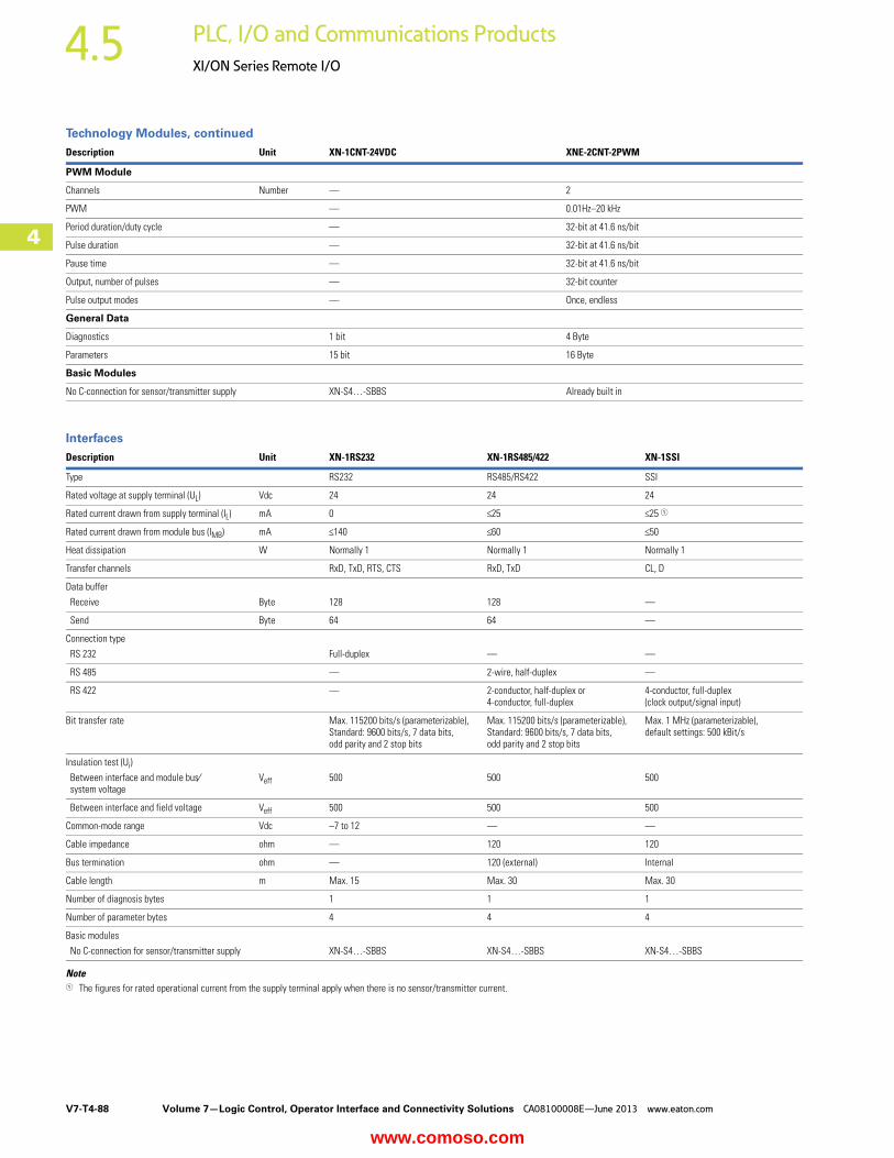
Description Unit XN-1CNT-24VDC XNE-2CNT-2PWM
PWM Module
Channels Number — 2
PWM — 0.01Hz–20 kHz
Period duration/duty cycle — 32-bit at 41.6 ns/bit
Pulse duration — 32-bit at 41.6 ns/bit
Pause time — 32-bit at 41.6 ns/bit
Output, number of pulses — 32-bit counter
Pulse output modes — Once, endless
General Data
Diagnostics 1 bit 4 Byte
Parameters 15 bit 16 Byte
Basic Modules
No C-connection for sensor/transmitter supply XN-S4…-SBBS Already built in
Description Unit XN-1RS232 XN-1RS485/422 XN-1SSI
Type RS232 RS485/RS422 SSI
Rated voltage at supply terminal (UL) Vdc 24 24 24
Rated current drawn from supply terminal (IL) mA 0 <25 <25 1
Rated current drawn from module bus (IMB) mA <140 <60 <50
Heat dissipation W Normally 1 Normally 1 Normally 1
Transfer channels RxD, TxD, RTS, CTS RxD, TxD CL, D
Data buffer
Receive Byte 128 128 —
Send Byte 64 64 —
Connection type
RS 232 Full-duplex — —
RS 485 — 2-wire, half-duplex —
RS 422 — 2-conductor, half-duplex or 4-conductor, full-duplex
4-conductor, full-duplex (clock output/signal input)
Bit transfer rate Max. 115200 bits/s (parameterizable), Standard: 9600 bits/s, 7 data bits, odd parity and 2 stop bits
Max. 115200 bits/s (parameterizable), Standard: 9600 bits/s, 7 data bits, odd parity and 2 stop bits
Max. 1 MHz (parameterizable),default settings: 500 kBit/s
Insulation test (Ui)
Between interface and module bus⁄system voltage
Veff 500 500 500
Between interface and field voltage Veff 500 500 500
Common-mode range Vdc –7 to 12 — —
Cable impedance ohm — 120 120
Bus termination ohm — 120 (external) Internal
Cable length m Max. 15 Max. 30 Max. 30
Number of diagnosis bytes 1 1 1
Number of parameter bytes 4 4 4
Basic modules
No C-connection for sensor/transmitter supply XN-S4…-SBBS XN-S4…-SBBS XN-S4…-SBBS
www.comoso.com

Volume 7—Logic Control, Operator Interface and Connectivity Solutions CA08100008E—June 2013 www.eaton.com V7-T4-89
4
4
4
4
4
4
4
4
4
4
4
4
4
4
4
4
4
4
4
4
4
4
4
4
4
4
4
4
4
4
4.5PLC, I/O and Communications Products
XI/ON Series Remote I/O
Connection DiagramsGateway XN…GWBR_
24V Supply from Gateway (UL) and System Bus (Usys)
Bus Refreshing Modules
XN-P3x-SBB with Gateway Power SupplyXN-P3…-SBB-B without Gateway Power Supply
XN-P4…-SBBC with Gateway Power SupplyXN-P4…-SBBC-B without Gateway Power Supply
Power Feeding Modules
XN-P3…-SBB for XN-PF-24VDC-D
XN-P3…-SBB for XN-PF-120/230VAC-D
XN-P4…-SBBC for XN-PF-24VDC-D
XN-P4…-SBB for XN-PF-120/230VAC-D
24V
24V
24V
Module Bus Supply
Fieldbus Supply
24V
24V
Module Bus Supply
Fieldbus Supply
24V 24V
www.comoso.com

V7-T4-90 Volume 7—Logic Control, Operator Interface and Connectivity Solutions CA08100008E—June 2013 www.eaton.com
4
4
4
4
4
4
4
4
4
4
4
4
4
4
4
4
4
4
4
4
4
4
4
4
4
4
4
4
4
4
4.5 PLC, I/O and Communications Products
XI/ON Series Remote I/O
Digital Input Modules
XN-S3…-SBB for XN-2DI-24VDC-P
XN-S3…-SBB for XN-2DI-24VDC-N
XN-S3…-SBB for XN-2DI-120/230VAC
XN-S4…-SBBC for XN-2DI-24VDC-P
XN-S4…-SBBC for XN-2DI-24VDC-N
XN-S4…-SBBC for XN-2DI-120/230VAC
www.comoso.com

Volume 7—Logic Control, Operator Interface and Connectivity Solutions CA08100008E—June 2013 www.eaton.com V7-T4-91
4
4
4
4
4
4
4
4
4
4
4
4
4
4
4
4
4
4
4
4
4
4
4
4
4
4
4
4
4
4
4.5PLC, I/O and Communications Products
XI/ON Series Remote I/O
XN-S4…-SBBS for XN-4DI-24VDC-P
XN-S4…-SBBS for XN-4DI-24VDC-N
XN-B3…-SBB for XN-16DI-24VDC-P
XN-S6…-SBBSBB for XN-4DI-24VDC-P
XN-S6…-SBBSBB for XN-4DI-24VDC-N
XN-B4…-SBBC for XN-16DI-24VDC-P
www.comoso.com

V7-T4-92 Volume 7—Logic Control, Operator Interface and Connectivity Solutions CA08100008E—June 2013 www.eaton.com
4
4
4
4
4
4
4
4
4
4
4
4
4
4
4
4
4
4
4
4
4
4
4
4
4
4
4
4
4
4
4.5 PLC, I/O and Communications Products
XI/ON Series Remote I/O
XN-B6…-SBBSBB for XN-32DI-24VDC-P XNE-8DI-24VDC-P
XNE-16DI-24VDC-P
24V
24V
www.comoso.com

Volume 7—Logic Control, Operator Interface and Connectivity Solutions CA08100008E—June 2013 www.eaton.com V7-T4-93
4
4
4
4
4
4
4
4
4
4
4
4
4
4
4
4
4
4
4
4
4
4
4
4
4
4
4
4
4
4
4.5PLC, I/O and Communications Products
XI/ON Series Remote I/O
Digital Output Modules
XN-S3…-SBC for XN-2DO-24VDC-0.5A-P and XN-2DO-24VDC-2A-P
XN-S3…-SBC for XN-2DO-24VDC-0.5A-N
XN-S3…-SBC for XN-2DO-120/230VAC-0.5A
XN-S4…-SBCS for XN-4DO-24VDC-0.5A-P
XN-S4…-SBCS for XN-2DO-24VDC-0.5A-P andXN-2DO-24VDC-2A-P
XN-S4…-SBCS for XN-2DO-24VDC-0.5A-N
XN-S4…-SBCS for XN-2DO-120/230VAC-0.5A
XN-B3…-SBC for XN-16DO-24VDC-0.5A-P
www.comoso.com
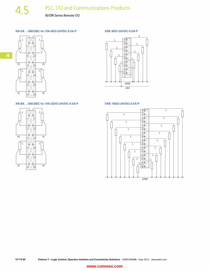
V7-T4-94 Volume 7—Logic Control, Operator Interface and Connectivity Solutions CA08100008E—June 2013 www.eaton.com
4
4
4
4
4
4
4
4
4
4
4
4
4
4
4
4
4
4
4
4
4
4
4
4
4
4
4
4
4
4
4.5 PLC, I/O and Communications Products
XI/ON Series Remote I/O
XN-S6…-SBCSBC for XN-4DO-24VDC-0.5A-P
XN-B6…-SBCSBC for XN-32DO-24VDC-0.5A-P
XNE-8DO-24VDC-0.5A-P
XNE-16DO-24VDC-0.5A-P
24V
GND
GND
www.comoso.com

Volume 7—Logic Control, Operator Interface and Connectivity Solutions CA08100008E—June 2013 www.eaton.com V7-T4-95
4
4
4
4
4
4
4
4
4
4
4
4
4
4
4
4
4
4
4
4
4
4
4
4
4
4
4
4
4
4
4.5PLC, I/O and Communications Products
XI/ON Series Remote I/O
Analog Input Modules
XN-S3…-SBB for XN-1AI-I(0/4…20MA)XN-S3…-SBB for XN-1AI-U(-10/0…+10VDC)Analog Sensor/Transmitter, without Transmitter Supply
XN-S3…-SBB for XN-2AI-I(0/4…20MA), XN-2AI-U(-10/0…+10VDC)Analog Sensor/Transmitter, without Transmitter Supply
XN-S4…-SBBS for XN-2AI-I(0/4…20MA)Two-Conductor Connection without External Transmitter Supply
XN-S4…-SBBS for XN-1AI-I(0/4…20MA)XN-S4…-SBBS for XN-1AI-U(-10/0…+10VDC)Analog Transmitter with Non-Isolated Transmitter Supply
XN-S4…-SBBS for XN-2AI-I(0/4…20MA), XN-2AI-U(-10/0…+10VDC)Analog Transmitter with Non-Isolated Transmitter Supply
www.comoso.com
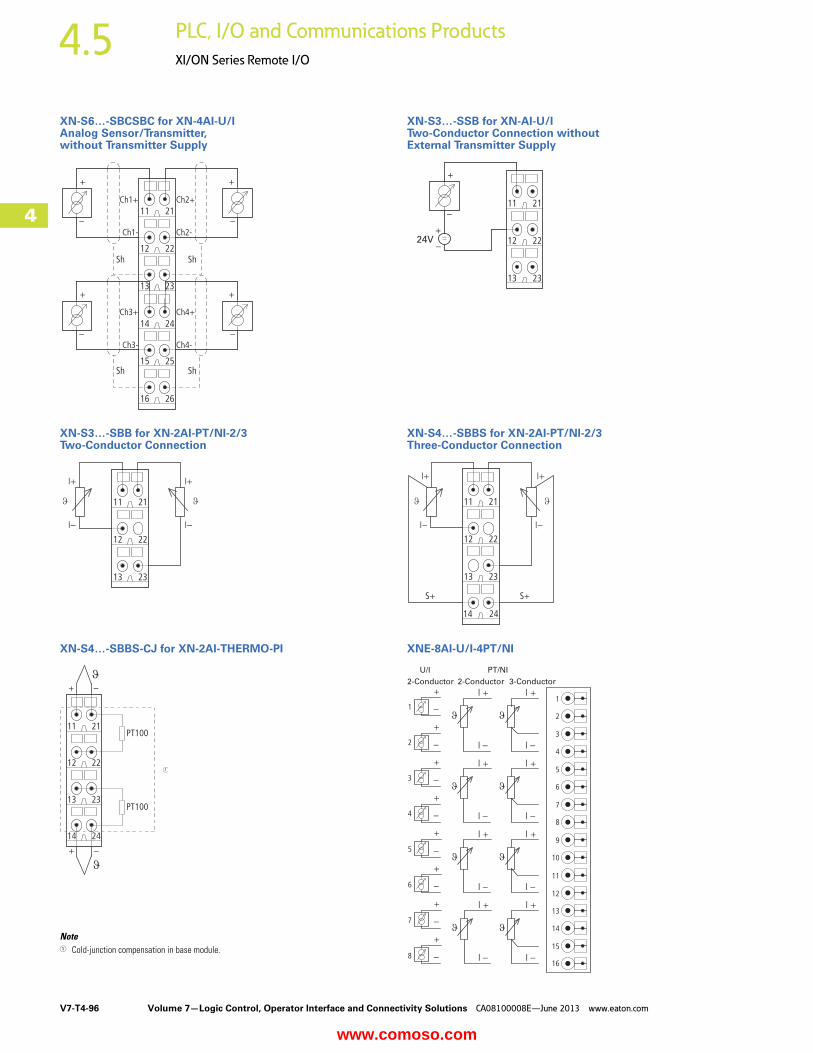
V7-T4-96 Volume 7—Logic Control, Operator Interface and Connectivity Solutions CA08100008E—June 2013 www.eaton.com
4
4
4
4
4
4
4
4
4
4
4
4
4
4
4
4
4
4
4
4
4
4
4
4
4
4
4
4
4
4
4.5 PLC, I/O and Communications Products
XI/ON Series Remote I/O
XN-S6…-SBCSBC for XN-4AI-U/IAnalog Sensor/Transmitter, without Transmitter Supply
XN-S3…-SBB for XN-2AI-PT/NI-2/3Two-Conductor Connection
XN-S4…-SBBS-CJ for XN-2AI-THERMO-PI
Note1 Cold-junction compensation in base module.
XN-S3…-SSB for XN-AI-U/ITwo-Conductor Connection without External Transmitter Supply
XN-S4…-SBBS for XN-2AI-PT/NI-2/3Three-Conductor Connection
XNE-8AI-U/I-4PT/NI
24V
U/I PT/NI
2-Conductor 2-Conductor 3-Conductor
www.comoso.com
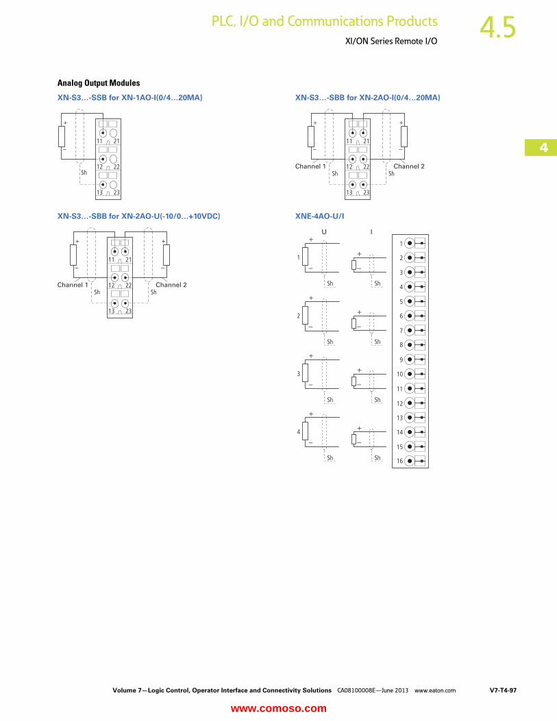
Volume 7—Logic Control, Operator Interface and Connectivity Solutions CA08100008E—June 2013 www.eaton.com V7-T4-97
4
4
4
4
4
4
4
4
4
4
4
4
4
4
4
4
4
4
4
4
4
4
4
4
4
4
4
4
4
4
4.5PLC, I/O and Communications Products
XI/ON Series Remote I/O
Analog Output Modules
XN-S3…-SSB for XN-1AO-I(0/4…20MA)
XN-S3…-SBB for XN-2AO-U(-10/0…+10VDC)
XN-S3…-SBB for XN-2AO-I(0/4…20MA)
XNE-4AO-U/I
Channel 1 Channel 2
Channel 1 Channel 2
U I
www.comoso.com

V7-T4-98 Volume 7—Logic Control, Operator Interface and Connectivity Solutions CA08100008E—June 2013 www.eaton.com
4
4
4
4
4
4
4
4
4
4
4
4
4
4
4
4
4
4
4
4
4
4
4
4
4
4
4
4
4
4
4.5 PLC, I/O and Communications Products
XI/ON Series Remote I/O
Relay Modules
XN-S4x…-SBBS with Externally Applied Supply and Common Potential Link for XN-2DO-R-NC
XN-S4x…-SBCS Supply via C-Rail and Common Potential Link for XN-2DO-R-NC
XN-S4x…-SBBS with Externally Applied Supply and Common Potential Link for XN-2DO-R-NO
Module Circuit XN-S4x…SBBS for XN-2DO-R-NC
Module Circuit XN-S4x…-SBCS for XN-2DO-R-NC
Module Circuit XN-S4x…-SBBS for XN-2DO-R-NO
Notes1 Linked in the electronics.2 Cross-link via QVR in the base module.3 Electronics module.4 Supply via C-rail.5 Maximum eight relay modules.
24V
PowerFeeding
Relais 1 Relais n
24V
www.comoso.com
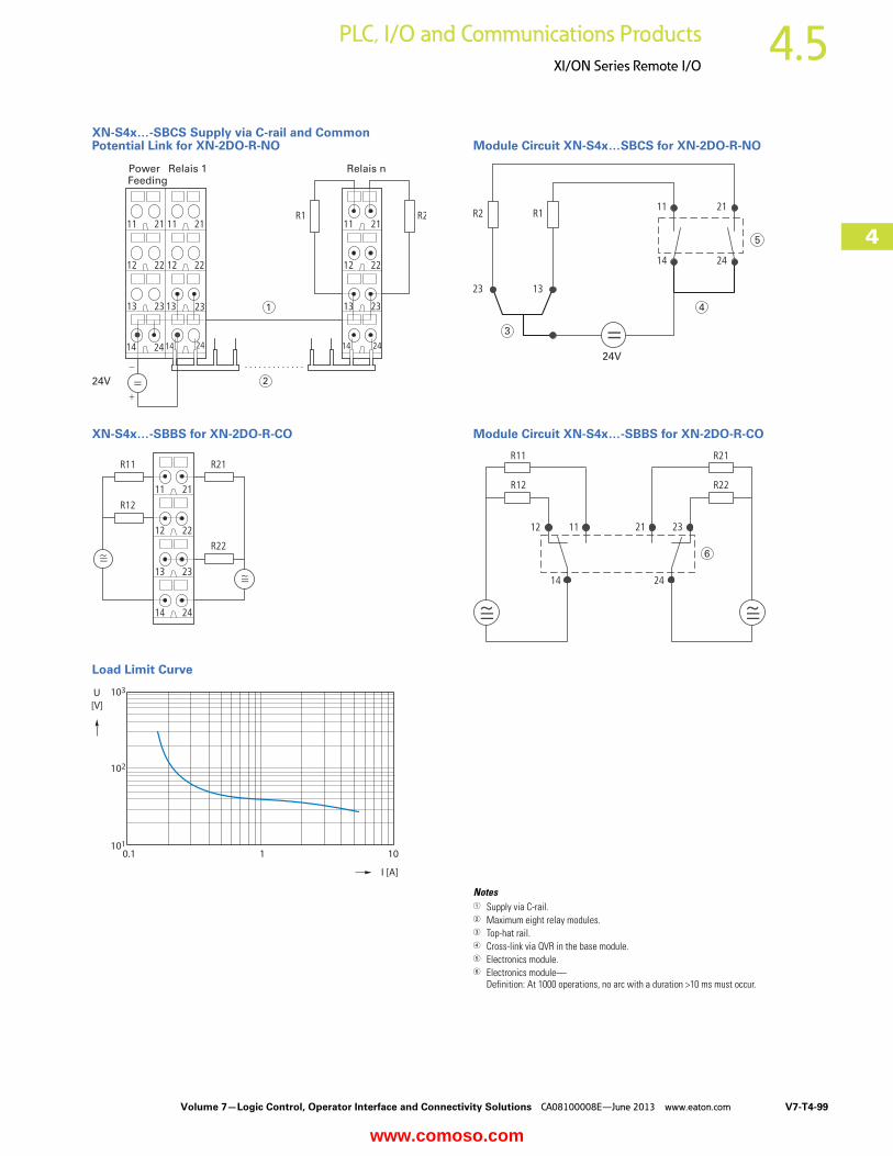
Volume 7—Logic Control, Operator Interface and Connectivity Solutions CA08100008E—June 2013 www.eaton.com V7-T4-99
4
4
4
4
4
4
4
4
4
4
4
4
4
4
4
4
4
4
4
4
4
4
4
4
4
4
4
4
4
4
4.5PLC, I/O and Communications Products
XI/ON Series Remote I/O
XN-S4x…-SBCS Supply via C-rail and Common Potential Link for XN-2DO-R-NO
XN-S4x…-SBBS for XN-2DO-R-CO
Load Limit Curve
Module Circuit XN-S4x…SBCS for XN-2DO-R-NO
Module Circuit XN-S4x…-SBBS for XN-2DO-R-CO
Notes1 Supply via C-rail.2 Maximum eight relay modules.3 Top-hat rail.4 Cross-link via QVR in the base module.5 Electronics module.6 Electronics module—
Definition: At 1000 operations, no arc with a duration >10 ms must occur.
24V
PowerFeeding
Relais 1 Relais n
24V
www.comoso.com

V7-T4-100 Volume 7—Logic Control, Operator Interface and Connectivity Solutions CA08100008E—June 2013 www.eaton.com
4
4
4
4
4
4
4
4
4
4
4
4
4
4
4
4
4
4
4
4
4
4
4
4
4
4
4
4
4
4
4.5 PLC, I/O and Communications Products
XI/ON Series Remote I/O
Serial Interfaces
XN-S4x…-SBBS for XN-1RS232 and D-Sub Plug
XN-S4x…-SBBS for XN-1SSI on an SSI Rotary Encoder
XN-S4x…SBBS for XN-1RS485/422 in RS422 Mode
XN-S4…-SBBS for XN-1RS485/422 in RS485 Mode
Technology Modules/CounterXN-S4…-SBBS for XN-1CNT-24VDC
XNE-2CNT-2PWM
SHLD
RTS
CTS
GND
TxD
RxD
CL+ CL-
GND GND GND
UL UL UL
D+ D-
SSI Device
Para
llel-
Seri
al-
Co
nvert
er
Op
to A
rray
An
alo
g A
rray
Data Out
Clock
TxD-TxD+
GND GND
SHLD
RxD+ RxD-
Data In
Data OutSHLD
SHLD
TxD-/RxD-/NTxD+/RxD+/P
GND GND Data In
Data Out
TxEnable
SHLD
SHLD SHLD
Counter Input A
or
Pulse Input
Counter Input B
or
Direction Input
M
M
Counter Input A, Pulse InputCounter 1
Synchronization Z
Counter Input B, Directional Input
Supply 24 Vdc
Supply GND
Output PWM
Output Direction
GND
Drive 1
Counter Input A, Pulse InputCounter 2
Synchronization Z
Counter Input B, Directional Input
Supply 24 Vdc
Supply GND
Output PWM
Output Direction
GND
Drive 2
www.comoso.com
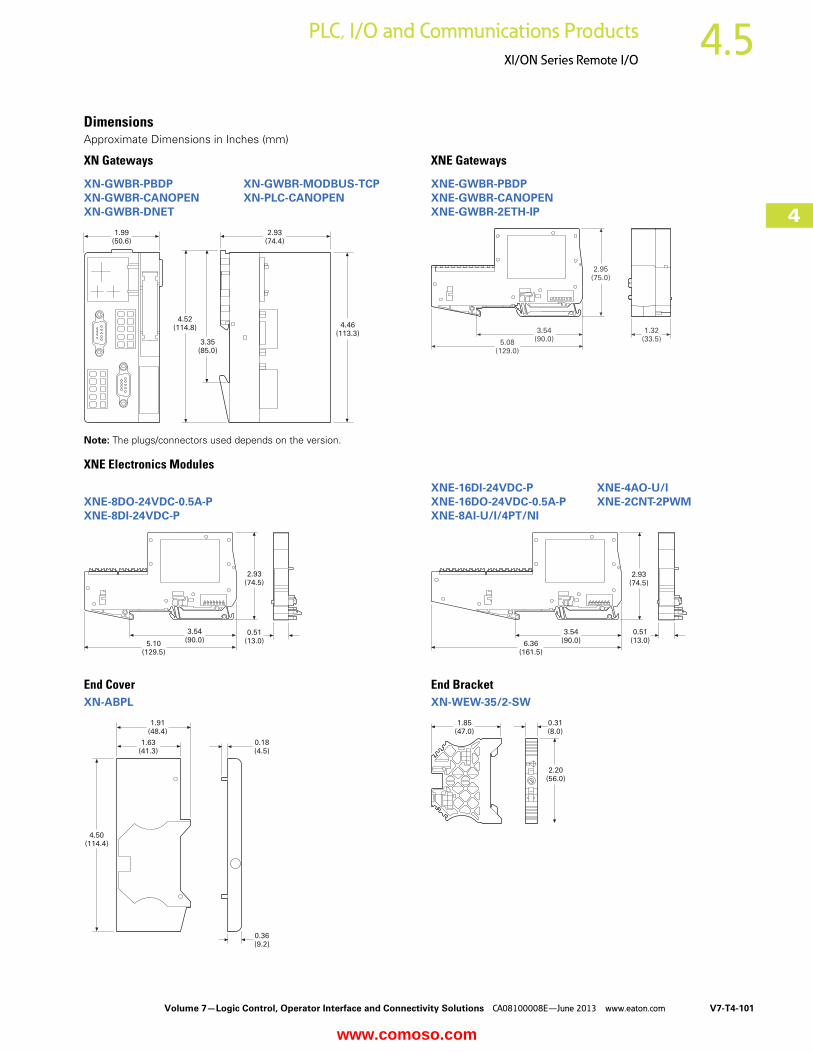
Volume 7—Logic Control, Operator Interface and Connectivity Solutions CA08100008E—June 2013 www.eaton.com V7-T4-101
4
4
4
4
4
4
4
4
4
4
4
4
4
4
4
4
4
4
4
4
4
4
4
4
4
4
4
4
4
4
4.5PLC, I/O and Communications Products
XI/ON Series Remote I/O
DimensionsApproximate Dimensions in Inches (mm)
XN Gateways XNE Gateways
Note: The plugs/connectors used depends on the version.
XNE Electronics Modules
End CoverXN-ABPL
End BracketXN-WEW-35/2-SW
XN-GWBR-PBDP XN-GWBR-MODBUS-TCPXN-GWBR-CANOPEN XN-PLC-CANOPENXN-GWBR-DNET
1.99(50.6)
2.93(74.4)
4.46(113.3)
4.52(114.8)
3.35(85.0)
XNE-GWBR-PBDPXNE-GWBR-CANOPENXNE-GWBR-2ETH-IP
5.08(129.0)
3.54(90.0)
2.95(75.0)
1.32(33.5)
XNE-8DO-24VDC-0.5A-PXNE-8DI-24VDC-P
5.10(129.5)
3.54(90.0)
0.51(13.0)
2.93(74.5)
4.50(114.4)
0.36(9.2)
0.18(4.5)
1.63(41.3)
1.91(48.4)
XNE-16DI-24VDC-P XNE-4AO-U/IXNE-16DO-24VDC-0.5A-P XNE-2CNT-2PWMXNE-8AI-U/I/4PT/NI
6.36(161.5)
3.54(90.0)
2.93(74.5)
0.51(13.0)
1.85(47.0)
0.31(8.0)
2.20(56.0)
www.comoso.com
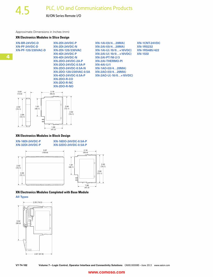
V7-T4-102 Volume 7—Logic Control, Operator Interface and Connectivity Solutions CA08100008E—June 2013 www.eaton.com
4
4
4
4
4
4
4
4
4
4
4
4
4
4
4
4
4
4
4
4
4
4
4
4
4
4
4
4
4
4
4.5 PLC, I/O and Communications Products
XI/ON Series Remote I/O
Approximate Dimensions in Inches (mm)
XN Electronics Modules in Slice Design
XN Electronics Modules in Block Design
XN Electronics Modules Completed with Base ModuleAll Types
XN-BR-24VDC-D XN-2DI-24VDC-P XN-1AI-I(0/4…20MA) XN-1CNT-24VDCXN-PF-24VDC-D XN-2DI-24VDC-N XN-2AI-I(0/4…20MA) XN-1RS232XN-PF-120/230VAC-D XN-2DI-120/230VAC XN-1AI-U(-10/0…+10VDC) XN-1RS485/422
XN-4DI-24VDC-P XN-2AI-U(-10/0…+10VDC) XN-1SSIXN-4DI-24VDC-N XN-2AI-PT/NI-2/3XN-2DO-24VDC-2A-P XN-2AI-THERMO-PIXN-2DO-24VDC-0.5A-P XN-4AI-U/IXN-2DO-24VDC-0.5A-N XN-1AO-I(0/4…20MA)XN-2DO-120/230VAC-0.5A XN-2AO-I(0/4…20MA)XN-4DO-24VDC-0.5A-P XN-2AO-U(-10/0…+10VDC)XN-2DO-R-COXN-2DO-R-NCXN-2DO-R-NO
XN-16DI-24VDC-P XN-16DO-24VDC-0.5A-PXN-32DI-24VDC-P XN-32DO-24VDC-0.5A-P
2.92(74.1)
2.84(72.1)
0.50(12.6)
1.81(46.1)
1.86(47.3)
2.18(55.4)
2.84(72.1)
2.92(74.1)
3.97(100.8)
2.92(74.1)
2.84(72.1)
1.81(46.1)
2.18(55.4)
1.86(47.3)
2.84(72.1)
2.92(74.1)
2.93 (74.5)
2.67 (67.8)
3.54(90.0)
www.comoso.com
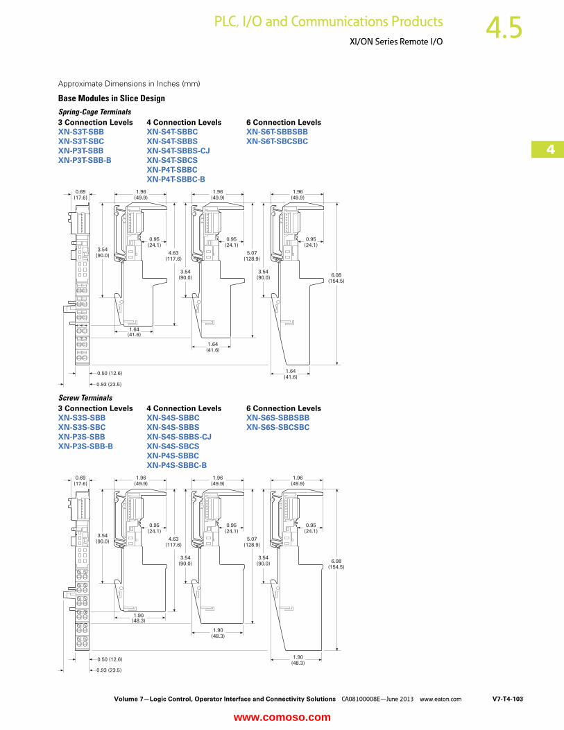
Volume 7—Logic Control, Operator Interface and Connectivity Solutions CA08100008E—June 2013 www.eaton.com V7-T4-103
4
4
4
4
4
4
4
4
4
4
4
4
4
4
4
4
4
4
4
4
4
4
4
4
4
4
4
4
4
4
4.5PLC, I/O and Communications Products
XI/ON Series Remote I/O
Approximate Dimensions in Inches (mm)
Base Modules in Slice DesignSpring-Cage Terminals
Screw Terminals
3 Connection Levels 4 Connection Levels 6 Connection LevelsXN-S3T-SBB XN-S4T-SBBC XN-S6T-SBBSBBXN-S3T-SBC XN-S4T-SBBS XN-S6T-SBCSBCXN-P3T-SBB XN-S4T-SBBS-CJXN-P3T-SBB-B XN-S4T-SBCS
XN-P4T-SBBCXN-P4T-SBBC-B
0.69(17.6)
1.96(49.9)
1.96(49.9)
1.96(49.9)
3.54(90.0)
0.95(24.1)
0.95(24.1)
0.95(24.1)
4.63(117.6)
5.07(128.9)
6.08(154.5)
1.64(41.6)
1.64(41.6)
1.64(41.6)
3.54(90.0)
3.54(90.0)
0.50 (12.6)
0.93 (23.5)
3 Connection Levels 4 Connection Levels 6 Connection LevelsXN-S3S-SBB XN-S4S-SBBC XN-S6S-SBBSBBXN-S3S-SBC XN-S4S-SBBS XN-S6S-SBCSBCXN-P3S-SBB XN-S4S-SBBS-CJXN-P3S-SBB-B XN-S4S-SBCS
XN-P4S-SBBCXN-P4S-SBBC-B
0.69(17.6)
1.96(49.9)
1.96(49.9)
1.96(49.9)
3.54(90.0)
0.95(24.1)
0.95(24.1)
0.95(24.1)
4.63(117.6)
5.07(128.9)
6.08(154.5)
1.90(48.3)
1.90(48.3)
1.90(48.3)
3.54(90.0)
3.54(90.0)
0.50 (12.6)
0.93 (23.5)
www.comoso.com
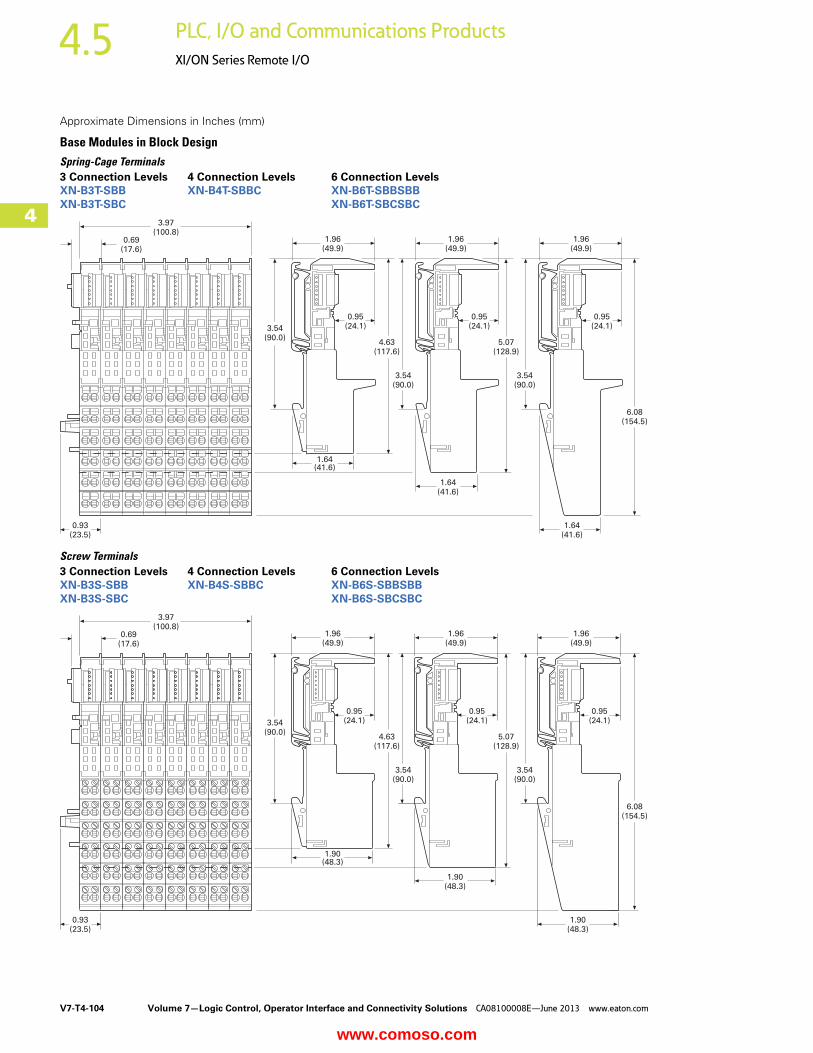
V7-T4-104 Volume 7—Logic Control, Operator Interface and Connectivity Solutions CA08100008E—June 2013 www.eaton.com
4
4
4
4
4
4
4
4
4
4
4
4
4
4
4
4
4
4
4
4
4
4
4
4
4
4
4
4
4
4
4.5 PLC, I/O and Communications Products
XI/ON Series Remote I/O
Approximate Dimensions in Inches (mm)
Base Modules in Block DesignSpring-Cage Terminals
Screw Terminals
3 Connection Levels 4 Connection Levels 6 Connection LevelsXN-B3T-SBB XN-B4T-SBBC XN-B6T-SBBSBBXN-B3T-SBC XN-B6T-SBCSBC
3.97(100.8)
1.96(49.9)
1.96(49.9)
1.96(49.9)
0.69(17.6)
0.93(23.5)
0.95(24.1)
0.95(24.1)
0.95(24.1)3.54
(90.0)
1.64(41.6)
1.64(41.6)
1.64(41.6)
4.63(117.6)
3.54(90.0)
5.07(128.9)
3.54(90.0)
6.08(154.5)
3 Connection Levels 4 Connection Levels 6 Connection LevelsXN-B3S-SBB XN-B4S-SBBC XN-B6S-SBBSBBXN-B3S-SBC XN-B6S-SBCSBC
3.97(100.8)
1.96(49.9)
1.96(49.9)
1.96(49.9)
0.69(17.6)
0.93(23.5)
0.95(24.1)
0.95(24.1)
0.95(24.1)3.54
(90.0)
1.90(48.3)
1.90(48.3)
1.90(48.3)
4.63(117.6)
3.54(90.0)
5.07(128.9)
3.54(90.0)
6.08(154.5)
www.comoso.com