X3 Small Mill - Model Engineering | arceurotrade.co.uk
28
A picture story book to help you dismantle and reassemble your Sieg X3 Small Mill Arc Euro Trade Ltd. 10 Archdale Street, Syston, Leicester, LE7 1NA. Web: www.arceurotrade.co.uk Phone: 0116 269 5693. X3 Small Mill Dismantling and Reassembly Guide - Page 1 - © Arc Euro Trade Ltd, England 2012 © Arc Euro Trade Ltd, England 2012
Transcript of X3 Small Mill - Model Engineering | arceurotrade.co.uk

A picture story book to help you dismantle and reassemble your Sieg X3 Small Mill
Arc Euro Trade Ltd.10 Archdale Street, Syston, Leicester, LE7 1NA.Web: www.arceurotrade.co.uk Phone: 0116 269 5693.
X3 Small Mill
Dismantling and Reassembly Guide
- Page 1 -
© A
rc E
uro
Trad
e Lt
d, E
ngla
nd 2
012
© A
rc E
uro
Trad
e Lt
d, E
ngla
nd 2
012

- Page 2 -
1: Presenting the case for the defence today is our engineer Geoff Watson. Geoff has worked on many X3 mills and by now, knows most of the wrinkles.
2: The mill - out of the box and all ready to start work on. 3: Remove the polycarbonate front guard
4: Loosen the drawbar...
- Page 2 -
5: ...and give it a tap to release the taper... 6: ...then remove the drawbar and drill chuck
There is no doubt that the Sieg X3 is currently one of the most popular small milling/drilling machines available to model engineers today. It has a well proportioned dovetailed cast iron column and head, a decent sized table with T-slots and coolant trough. With it’s variable speed DC motor + 2 speed gearbox, the X3 is available in both metric and imperial options and a choice of either an MT3 or R8 spindle. This picture story guide is designed to help you dismantle, reassemble, lubricate and make the proper adjustments to your Mill. Before dismantling your X3 Small Mill, you should read through the entire guide and assess that you have the required equipment and skills to
complete the task. Although not expressly stated at each stage in this guide, every part is thoroughly cleaned in a paraffi n type degreaser before reassembly. For lubrication, we recommend Molyslip HSB grease (ARC code: 170-100-10300), and a good quality lubricating oil such as Rock Oil HLP 32 Hydraulic Oil (ARC code: 170-150-00400). We do not recommend using automotive engine oil or 3-in-1 oil.Update:Please use Molyslip HSB grease (or similar) for lubrication wherever the guide shows the use of Copperslip grease.
PLEASE READ THIS FIRST©
Arc
Eur
o Tr
ade
Ltd,
Eng
land
201
2©
Arc
Eur
o Tr
ade
Ltd,
Eng
land
201
2
- Page 3 -
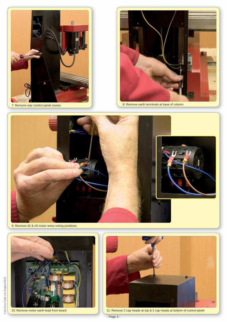
7: Remove rear control panel covers 8: Remove earth terminals at base of column
9: Remove #2 & #3 motor wires noting positions
10: Remove motor earth lead from board
- Page 3 -
11: Remove 2 cap heads at top & 2 cap heads at bottom of control panel
© A
rc E
uro
Trad
e Lt
d, E
ngla
nd 2
012
© A
rc E
uro
Trad
e Lt
d, E
ngla
nd 2
012
- Page 4 -
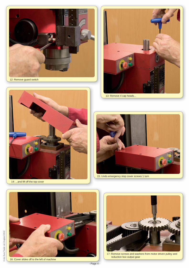
12: Remove guard switch
13: Remove 4 cap heads...
14: ...and lift off the top cover
15: Undo emergency stop cover screws 1 turn
- Page 4 -
16: Cover slides off to the left of machine
17: Remove screws and washers from motor driven pulley and reduction box output gear
© A
rc E
uro
Trad
e Lt
d, E
ngla
nd 2
012
© A
rc E
uro
Trad
e Lt
d, E
ngla
nd 2
012
- Page 5 -
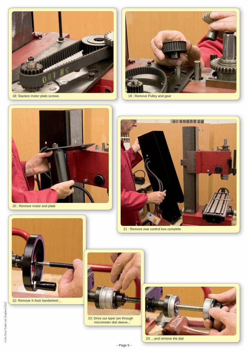
18: Slacken motor plate screws 19 : Remove Pulley and gear
20 : Remove motor and plate
21 : Remove rear control box complete
22: Remove X-Axis handwheel...
23: Drive out taper pin through micrometer dial sleeve...
24: ...and remove the dial
© A
rc E
uro
Trad
e Lt
d, E
ngla
nd 2
012
© A
rc E
uro
Trad
e Lt
d, E
ngla
nd 2
012
- Page 6 -
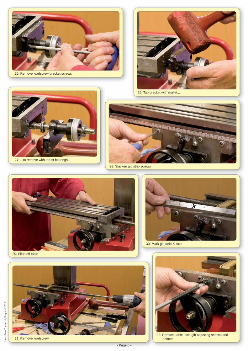
25: Remove leadscrew bracket screws
26: Tap bracket with mallet...
27: ...to remove with thrust bearings
28: Slacken gib strip screws
29: Slide off table
30: Mark gib strip X-Axis
- Page 6 -
31: Remove leadscrew32: Remove table lock, gib adjusting screws and
pointer
© A
rc E
uro
Trad
e Lt
d, E
ngla
nd 2
012
© A
rc E
uro
Trad
e Lt
d, E
ngla
nd 2
012
- Page 7 -
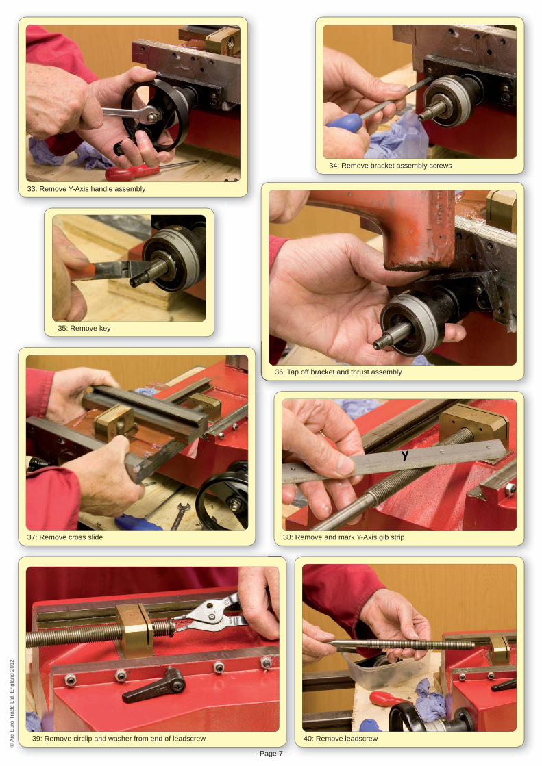
33: Remove Y-Axis handle assembly
34: Remove bracket assembly screws
35: Remove key
36: Tap off bracket and thrust assembly
37: Remove cross slide
- Page 7 -
39: Remove circlip and washer from end of leadscrew
38: Remove and mark Y-Axis gib strip
40: Remove leadscrew
© A
rc E
uro
Trad
e Lt
d, E
ngla
nd 2
012
© A
rc E
uro
Trad
e Lt
d, E
ngla
nd 2
012

- Page 8 -
41: Remove locking handle assembly and gib screws
42: Table and cross slide assembly removed
43: Wind head up to end of travel to remove gas strut screws - upper screw... 44: ...and lower screw
45: Remove gas strut
- Page 8 -
46: Place prop under head and wind down until the head just touches
47: Remove locking lever and cap heads from both side plates
© A
rc E
uro
Trad
e Lt
d, E
ngla
nd 2
012
© A
rc E
uro
Trad
e Lt
d, E
ngla
nd 2
012
- Page 9 -
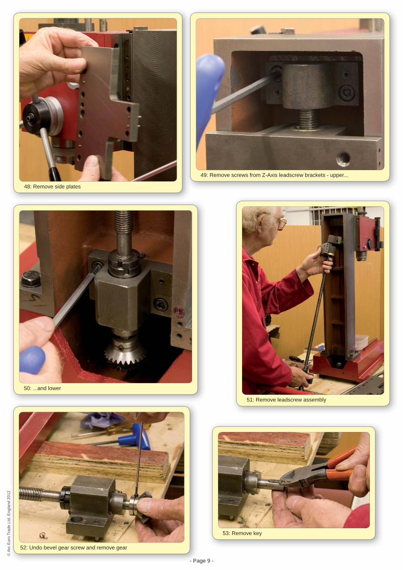
48: Remove side plates
49: Remove screws from Z-Axis leadscrew brackets - upper...
50: ...and lower
51: Remove leadscrew assembly
- Pa
52: Undo bevel gear screw and remove gear
53: Remove key
© A
rc E
uro
Trad
e Lt
d, E
ngla
nd 2
012
© A
rc E
uro
Trad
e Lt
d, E
ngla
nd 2
012

- Page 10 -
54: Remove taper pin 55: Remove lower thrust bearing block assembly noting orientation
56: Remove leadscrew from nut, pulling off top bearing bracket at the same time 57: Losen grub screw in bevel gear
58: Undo adjusting nuts and remove handwheel assembly
60: Remove screws from bracket
59: Remove key
61: Remove carrier bracket and thrust bearings
© A
rc E
uro
Trad
e Lt
d, E
ngla
nd 2
012
© A
rc E
uro
Trad
e Lt
d, E
ngla
nd 2
012
- Page 11 -
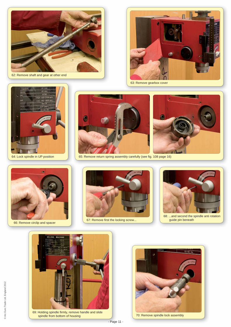
62: Remove shaft and gear at other end
63: Remove gearbox cover
64: Lock spindle in UP position 65: Remove return spring assembly carefully (see fi g. 108 page 16)
66: Remove circlip and spacer67: Remove fi rst the locking screw...
- Page
69: Holding spindle fi rmly, remove handle and slide spindle from bottom of housing 70: Remove spindle lock assembly
68: ...and second the spindle anti rotation guide pin beneath
© A
rc E
uro
Trad
e Lt
d, E
ngla
nd 2
012
© A
rc E
uro
Trad
e Lt
d, E
ngla
nd 2
012
- Page 12 -
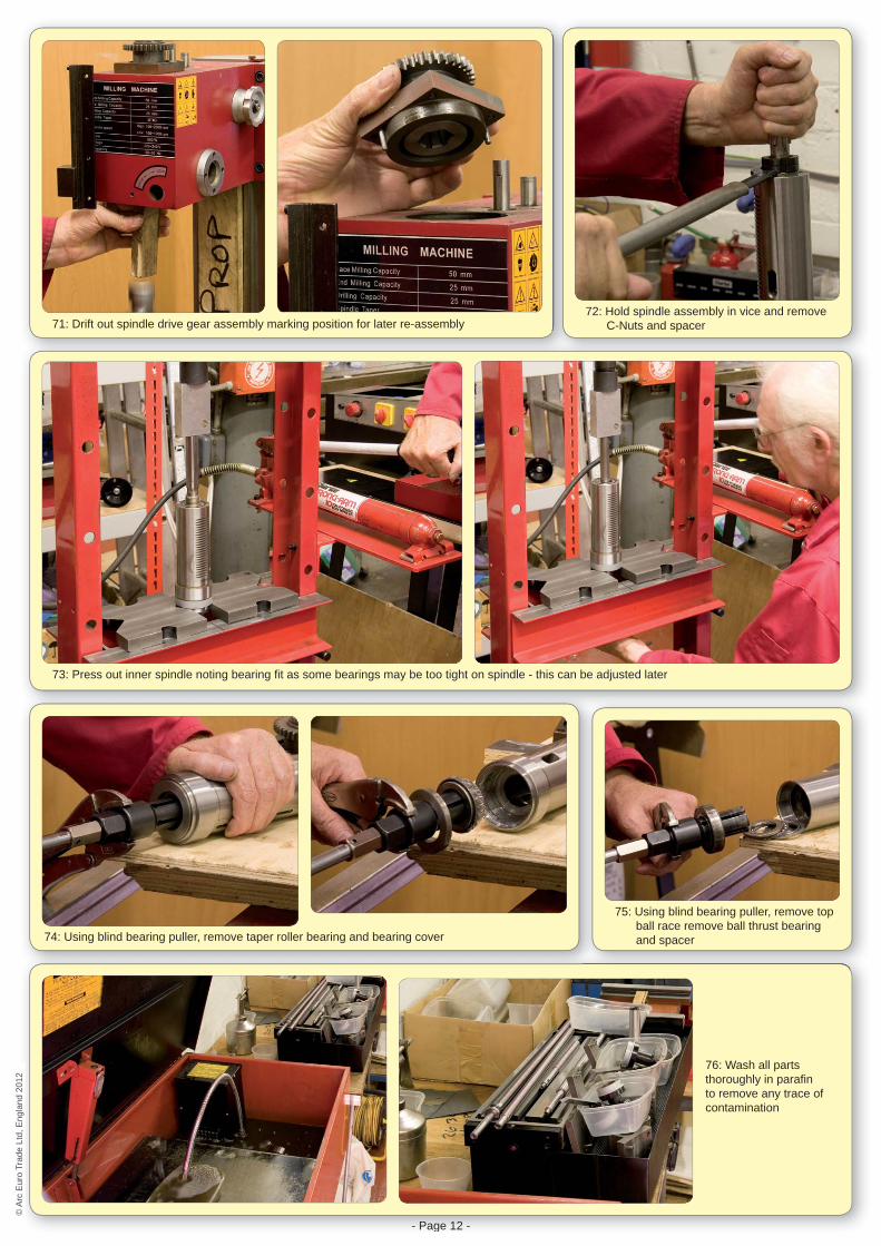
71: Drift out spindle drive gear assembly marking position for later re-assembly72: Hold spindle assembly in vice and remove
C-Nuts and spacer
73: Press out inner spindle noting bearing fi t as some bearings may be too tight on spindle - this can be adjusted later
74: Using blind bearing puller, remove taper roller bearing and bearing cover
- Page 12 -
76: Wash all parts thoroughly in parafi n to remove any trace of contamination
75: Using blind bearing puller, remove top ball race remove ball thrust bearing and spacer
© A
rc E
uro
Trad
e Lt
d, E
ngla
nd 2
012
© A
rc E
uro
Trad
e Lt
d, E
ngla
nd 2
012

- Page 13 -
77: If spindle bearing fi t feels overly tight, polish journals to suit. Reason:If the top ball race is too tight on the spindle, it will be diffi cult to obtain the correct bearing preload.
78: Spindle assembly parts
79: Press fl ange onto spindle
- Page 13 -
80: Grease taper roller and fi t to spindle sleeve 81: Fit Under oil seal
© A
rc E
uro
Trad
e Lt
d, E
ngla
nd 2
012
© A
rc E
uro
Trad
e Lt
d, E
ngla
nd 2
012
- Page 14 -
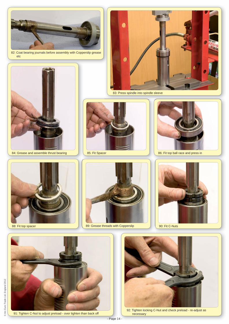
82: Coat bearing journals before assembly with Copperslip grease etc
84: Grease and assemble thrust bearing 85: Fit Spacer 86: Fit top ball race and press in
90: Fit C-Nuts89: Grease threads with Copperslip88: Fit top spacer
83: Press spindle into spindle sleeve
- Page 1
91: Tighten C-Nut to adjust preload - over tighten than back off
4 -
92: Tighten locking C-Nut and check preload - re-adjust as necessary©
Arc
Eur
o Tr
ade
Ltd,
Eng
land
201
2©
Arc
Eur
o Tr
ade
Ltd,
Eng
land
201
2
- Page 15 -
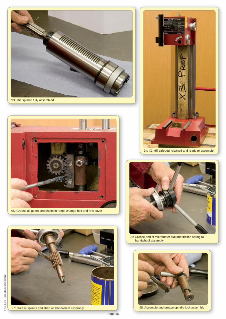
93: The spindle fully assembled
94: X3 Mill stripped, cleaned and ready to assemble
95: Grease all gears and shafts in range change box and refi t cover
96: Grease and fi t micrometer dial and friction spring to handwheel assembly
- Page 15 -
97: Grease splines and shaft on handwheel assembly 98: Assemble and grease spindle lock assembly
© A
rc E
uro
Trad
e Lt
d, E
ngla
nd 2
012
© A
rc E
uro
Trad
e Lt
d, E
ngla
nd 2
012
- Page 16 -
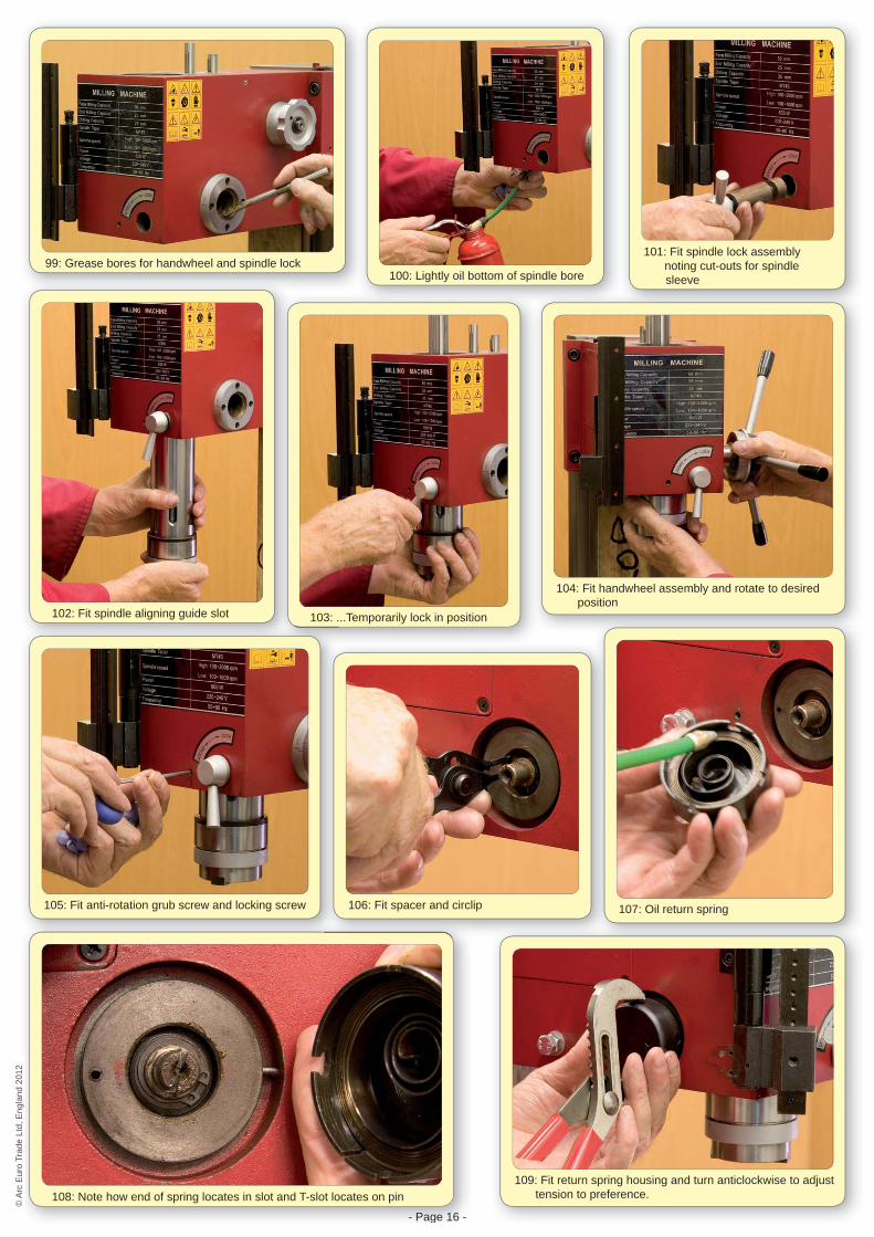
99: Grease bores for handwheel and spindle lock100: Lightly oil bottom of spindle bore
101: Fit spindle lock assembly noting cut-outs for spindle sleeve
102: Fit spindle aligning guide slot 103: ...Temporarily lock in position
104: Fit handwheel assembly and rotate to desired position
105: Fit anti-rotation grub screw and locking screw
- Page 16 -
108: Note how end of spring locates in slot and T-slot locates on pin
106: Fit spacer and circlip 107: Oil return spring
109: Fit return spring housing and turn anticlockwise to adjust tension to preference.
© A
rc E
uro
Trad
e Lt
d, E
ngla
nd 2
012
© A
rc E
uro
Trad
e Lt
d, E
ngla
nd 2
012
- Page 17 -
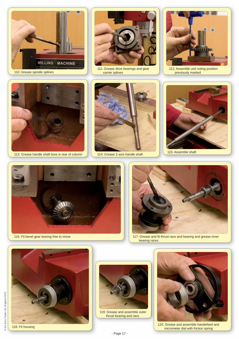
110: Grease spindle splines111: Grease drive bearings and gear
carrier splines112: Assemble unit noting position
previously marked
113: Grease handle shaft bore in rear of column 114: Grease Z-axis handle shaft115: Assemble shaft
116: Fit bevel gear leaving free to move
118: Fit housing
119: Grease and assemble outer thrust bearing and race
120: Grease and assemble handwheel and micrometer dial with friction spring
117: Grease and fi t thrust race and bearing and grease inner bearing races
© A
rc E
uro
Trad
e Lt
d, E
ngla
nd 2
012
© A
rc E
uro
Trad
e Lt
d, E
ngla
nd 2
012
- Page 18 -
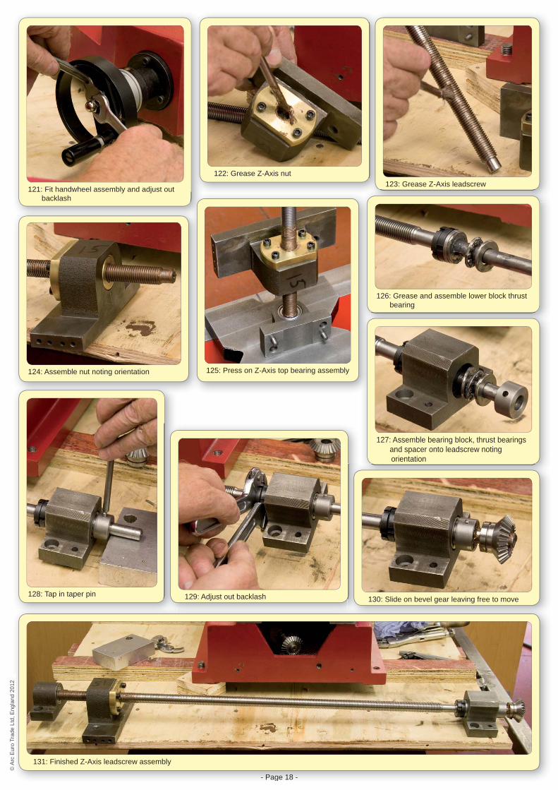
121: Fit handwheel assembly and adjust out backlash
122: Grease Z-Axis nut123: Grease Z-Axis leadscrew
124: Assemble nut noting orientation 125: Press on Z-Axis top bearing assembly
126: Grease and assemble lower block thrust bearing
127: Assemble bearing block, thrust bearings and spacer onto leadscrew noting orientation
128: Tap in taper pin 129: Adjust out backlash 130: Slide on bevel gear leaving free to move
- Page 18 -
131: Finished Z-Axis leadscrew assembly
© A
rc E
uro
Trad
e Lt
d, E
ngla
nd 2
012
© A
rc E
uro
Trad
e Lt
d, E
ngla
nd 2
012
- Page 19 -
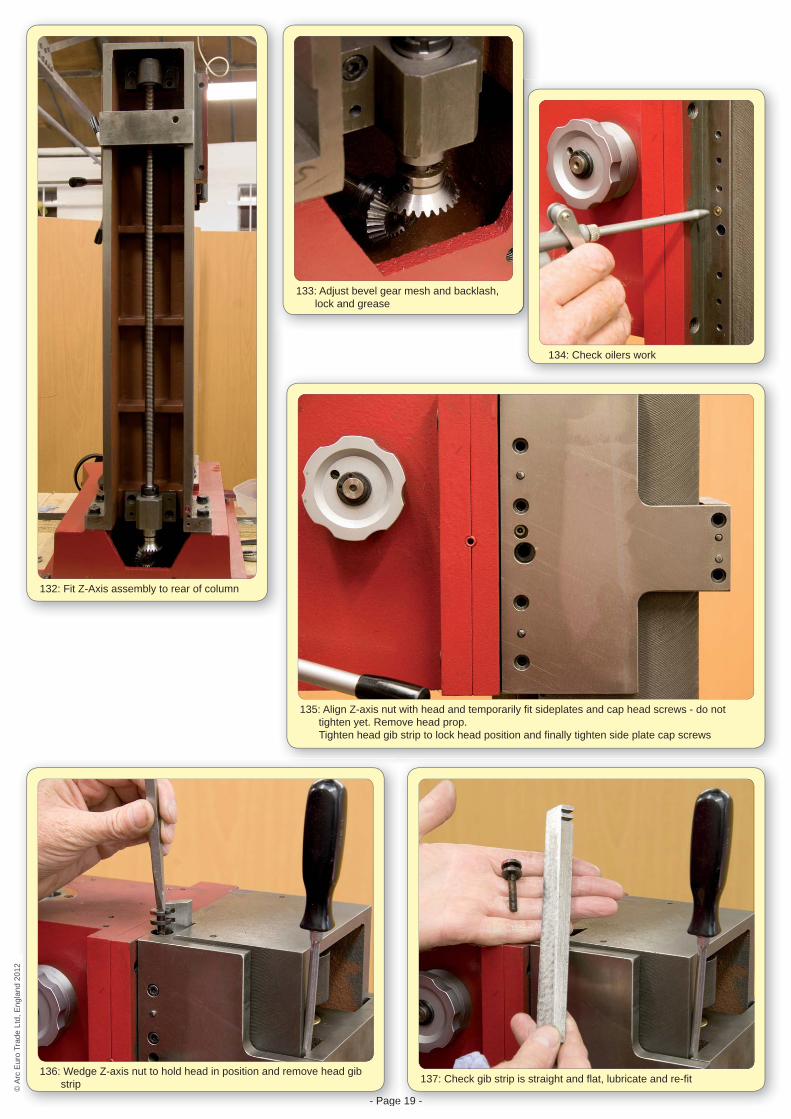
132: Fit Z-Axis assembly to rear of column
133: Adjust bevel gear mesh and backlash, lock and grease
134: Check oilers work
135: Align Z-axis nut with head and temporarily fi t sideplates and cap head screws - do not tighten yet. Remove head prop. Tighten head gib strip to lock head position and fi nally tighten side plate cap screws
- Page
136: Wedge Z-axis nut to hold head in position and remove head gib strip
19 -e
137: Check gib strip is straight and fl at, lubricate and re-fi t
© A
rc E
uro
Trad
e Lt
d, E
ngla
nd 2
012
© A
rc E
uro
Trad
e Lt
d, E
ngla
nd 2
012
- Page 20 -
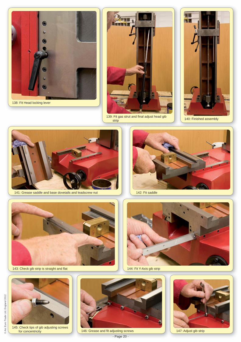
138: Fit Head locking lever
139: Fit gas strut and fi nal adjust head gib strip 140: Finished assembly
141: Grease saddle and base dovetails and leadscrew nut 142: Fit saddle
143: Check gib strip is straight and fl at
145: Check tips of gib adjusting screws for concentricity
144: Fit Y-Axis gib strip
- Page 20 -
146: Grease and fi t adjusting screws 147: Adjust gib strip
© A
rc E
uro
Trad
e Lt
d, E
ngla
nd 2
012
© A
rc E
uro
Trad
e Lt
d, E
ngla
nd 2
012
- Page 21 -
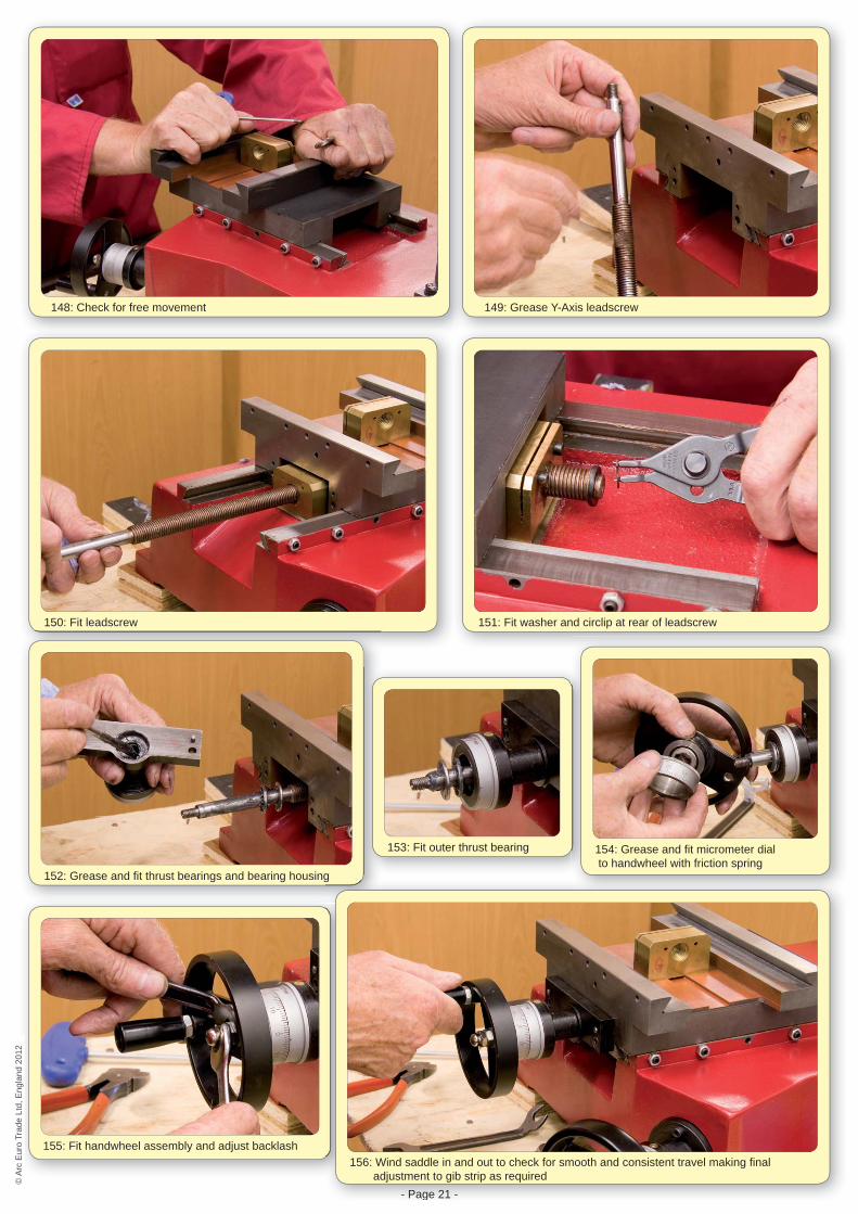
148: Check for free movement 149: Grease Y-Axis leadscrew
150: Fit leadscrew 151: Fit washer and circlip at rear of leadscrew
152: Grease and fi t thrust bearings and bearing housing
153: Fit outer thrust bearing 154: Grease and fi t micrometer dial to handwheel with friction spring
155: Fit handwheel assembly and adjust backlash
- Page 21 -
g
156: Wind saddle in and out to check for smooth and consistent travel making fi nal adjustment to gib strip as required©
Arc
Eur
o Tr
ade
Ltd,
Eng
land
201
2©
Arc
Eur
o Tr
ade
Ltd,
Eng
land
201
2
- Page 22 -
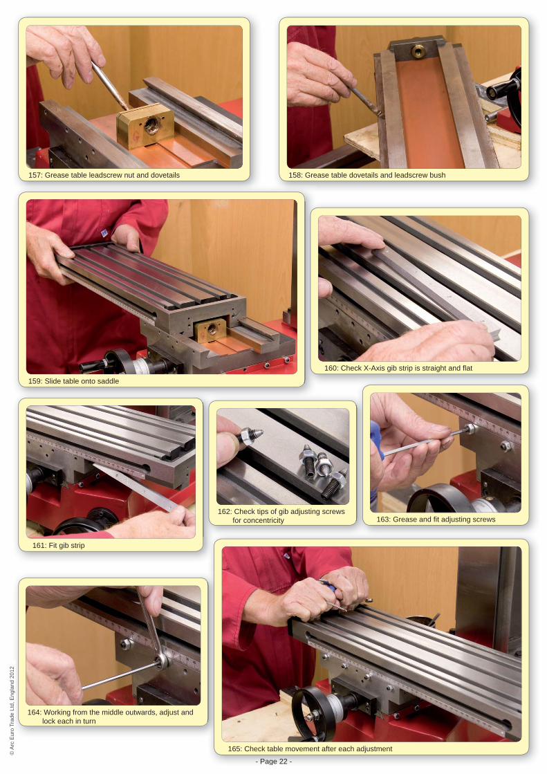
157: Grease table leadscrew nut and dovetails 158: Grease table dovetails and leadscrew bush
159: Slide table onto saddle
160: Check X-Axis gib strip is straight and fl at
161: Fit gib strip
162: Check tips of gib adjusting screws for concentricity 163: Grease and fi t adjusting screws
164: Working from the middle outwards, adjust and lock each in turn
- Page 22 -
165: Check table movement after each adjustment
© A
rc E
uro
Trad
e Lt
d, E
ngla
nd 2
012
© A
rc E
uro
Trad
e Lt
d, E
ngla
nd 2
012
- Page 23 -
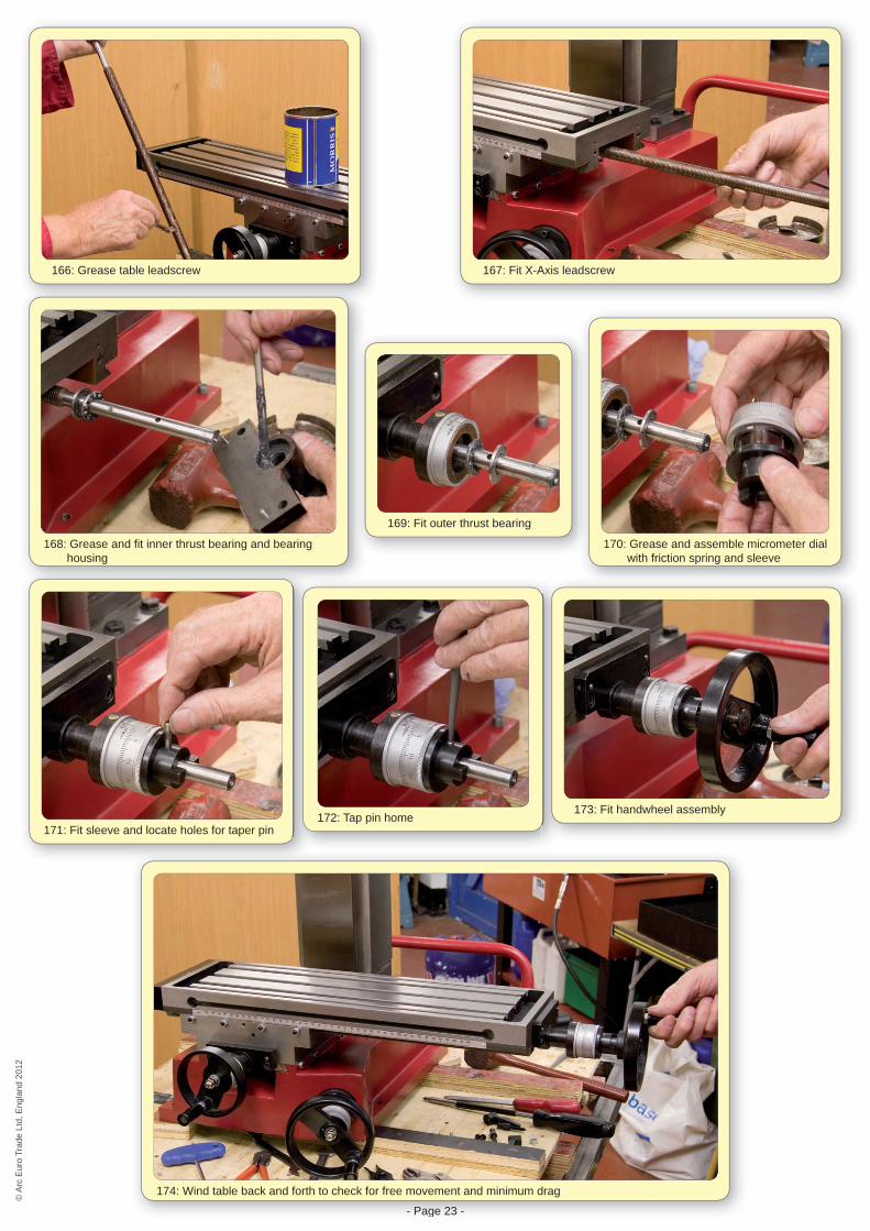
166: Grease table leadscrew 167: Fit X-Axis leadscrew
168: Grease and fi t inner thrust bearing and bearing housing
169: Fit outer thrust bearing
170: Grease and assemble micrometer dial with friction spring and sleeve
171: Fit sleeve and locate holes for taper pin172: Tap pin home
173: Fit handwheel assembly
- Page 23 -
174: Wind table back and forth to check for free movement and minimum drag
© A
rc E
uro
Trad
e Lt
d, E
ngla
nd 2
012
© A
rc E
uro
Trad
e Lt
d, E
ngla
nd 2
012
- Page 24 -
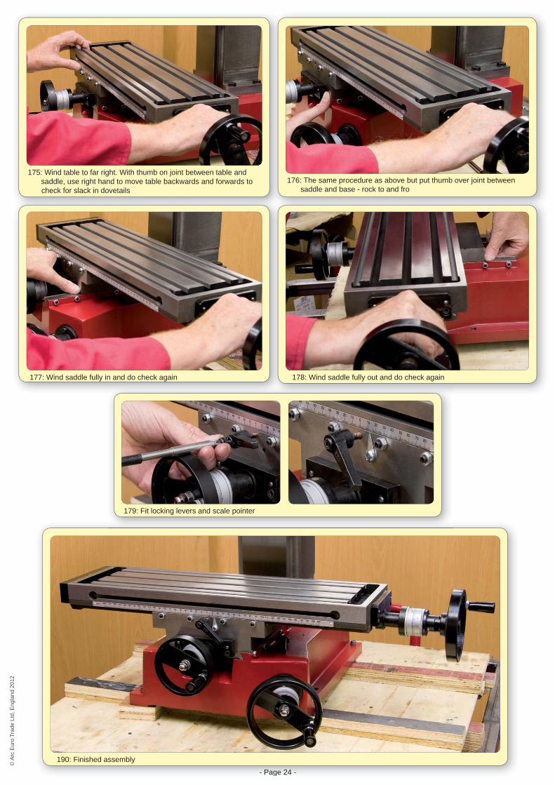
175: Wind table to far right. With thumb on joint between table and saddle, use right hand to move table backwards and forwards to check for slack in dovetails
176: The same procedure as above but put thumb over joint between saddle and base - rock to and fro
177: Wind saddle fully in and do check again 178: Wind saddle fully out and do check again
- Page 24 -
190: Finished assembly
179: Fit locking levers and scale pointer
© A
rc E
uro
Trad
e Lt
d, E
ngla
nd 2
012
© A
rc E
uro
Trad
e Lt
d, E
ngla
nd 2
012
- Page 25 -
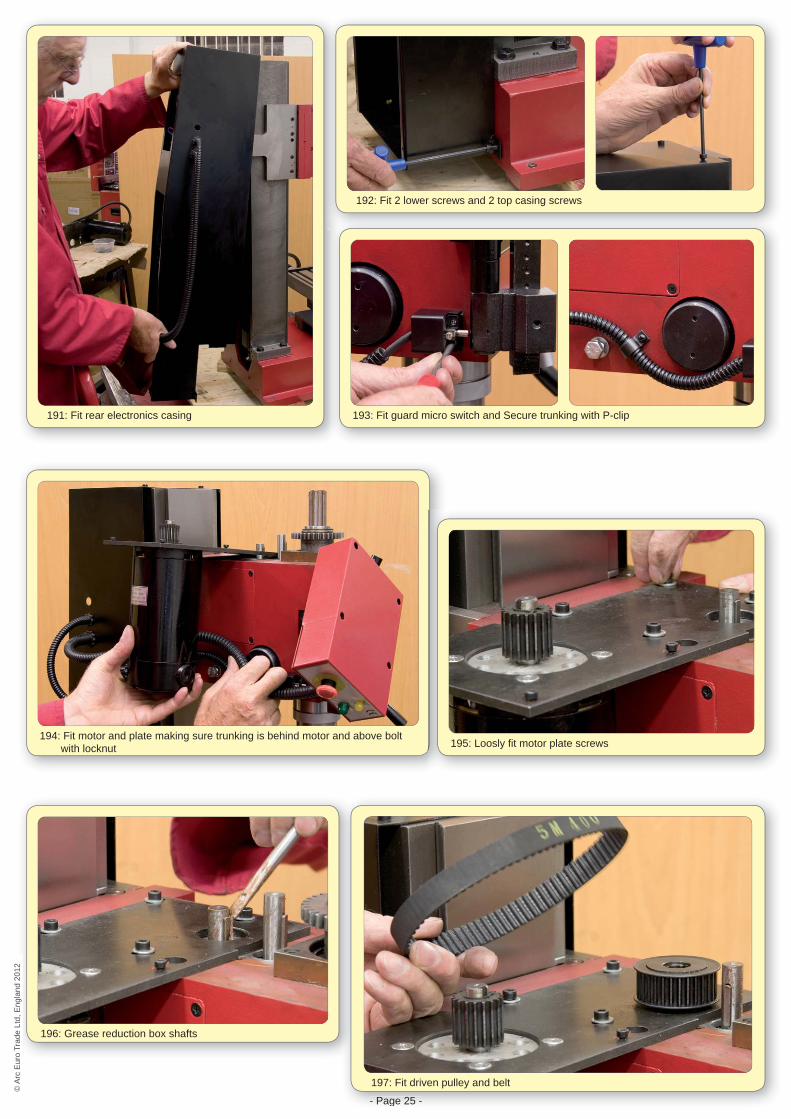
191: Fit rear electronics casing
192: Fit 2 lower screws and 2 top casing screws
193: Fit guard micro switch and Secure trunking with P-clip
194: Fit motor and plate making sure trunking is behind motor and above bolt with locknut 195: Loosly fi t motor plate screws
196: Grease reduction box shafts
- Page 25 -
197: Fit driven pulley and belt
© A
rc E
uro
Trad
e Lt
d, E
ngla
nd 2
012
© A
rc E
uro
Trad
e Lt
d, E
ngla
nd 2
012
- Page 26 -
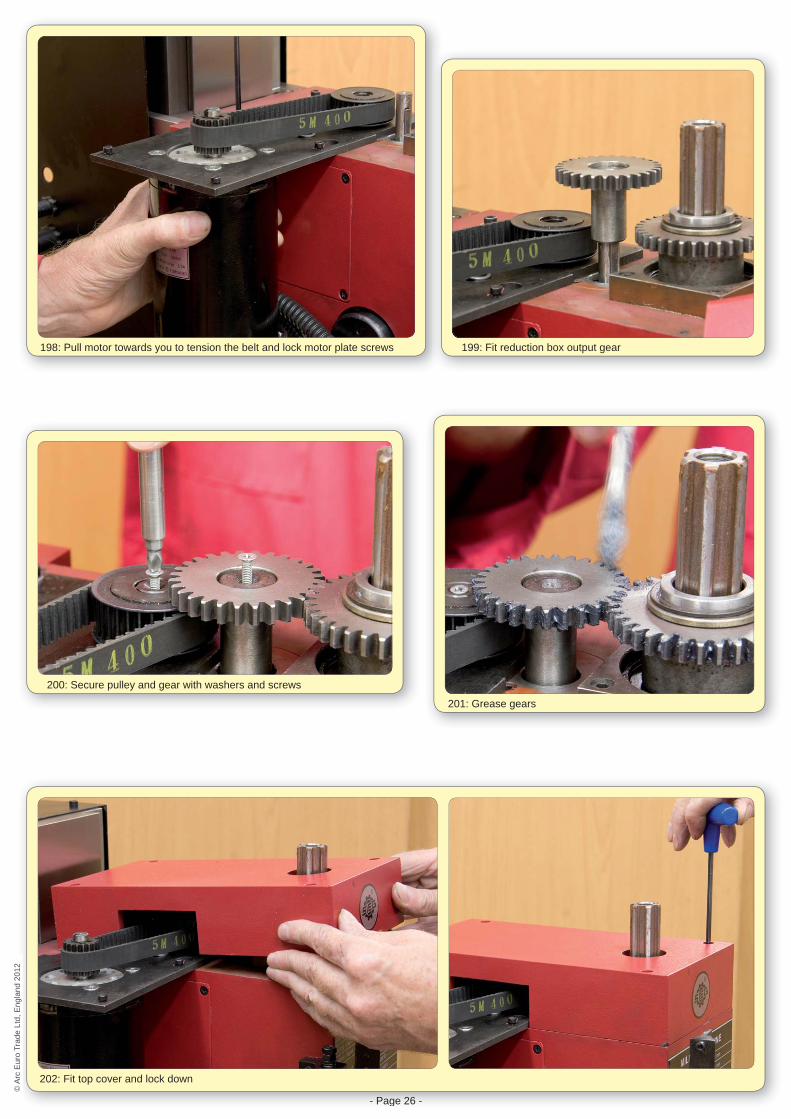
198: Pull motor towards you to tension the belt and lock motor plate screws 199: Fit reduction box output gear
200: Secure pulley and gear with washers and screws
201: Grease gears
- Page 26 -
202: Fit top cover and lock down
© A
rc E
uro
Trad
e Lt
d, E
ngla
nd 2
012
© A
rc E
uro
Trad
e Lt
d, E
ngla
nd 2
012

- Page 27 -
203: Fit stop switch housing - just slide on and pinch screws down
204: Thread motor wires through casing
205: Attach Brown and Blue wires to the forward/reverse switch as previously noted
206: Attach motor earth wire to the board
7 -
207: Fit earth wires to base of column. Cable tie any loose wires and replace covers©
Arc
Eur
o Tr
ade
Ltd,
Eng
land
201
2©
Arc
Eur
o Tr
ade
Ltd,
Eng
land
201
2

- Page 28 -- Page 28 -
© A
rc E
uro
Trad
e Lt
d, E
ngla
nd 2
012
© A
rc E
uro
Trad
e Lt
d, E
ngla
nd 2
012
Always follow the correct Start-Up Procedure:
1. Turn the Power Switch to 0 (off)2. Turn the Forward/Reverse Switch to 0 (off)3. Connect the 13amp plug to a suitable socket outlet
and switch on the power4. Select the High or Low range gear as required5. Rotate the Emergency Stop Switch to re-set6. Close the Guard7. Set the Speed Control Knob to a low speed
position8. Check there are no obstructions around the spindle
or cutter9. Turn the Power Switch to 1 (on)10. Set the Forward/Reverse Switch to the direction
you require11. Slowly turn the Speed Control Knob to the desired
speed
Running the spindle for the fi rst time:
1. Follow the Start-Up procedure with Low gear selected and the motor running forwards
2. Run for 10 minutes at a low RPM. (The machine should run smoothly with minimal noise and vibration. If not turn off the machine and investigate the cause of the problem)
3. Slowly increase the speed and run for 10 minutes at a medium RPM
4. Slowly increase the speed and run for 10 minutes at a high RPM
5. Stop the machine and repeat steps 1-4 above in High gear
6. Stop the machine and repeat steps 1-5 above with the motor in Reverse
Note: Failure to follow this procedure may cause rapid deterioration of the spindle and related parts.
The Completed Machine
WHEN CHANGING THE CUTTER OR SETTING UP, ALWAYS TURN THE POWER SWITCH TO 0 (OFF)WHEN CHANGING THE CUTTER OR SETTING UP, ALWAYS TURN THE POWER SWITCH TO 0 (OFF)