X-band RF Gun Development
3
X-BAND RF GUN DEVELOPMENT* A.E.Vlieks, V. Dolgashev, S. Tantawi, SLAC, Menlo Park, CA, 94025, USA S. Anderson, F. Hartemann, Roark Marsh, LLNL, Livermore, CA, 94550, U.S.A. Abstract In support of the MEGa-ray program at LLNL and the High Gradient research program at SLAC, a new X-band multi-cell RF gun is being developed. This gun, similar to earlier guns developed at SLAC for Compton X-ray source program, will be a standing wave structure made of 5.5 cells operating in the pi mode with copper cathode. This gun was designed following criteria used to build SLAC X-band high gradient accelerating structures. It is anticipated that this gun will operate with surface electric fields on the cathode of 200MeV/m with low breakdown rate. RF will be coupled into the structure through a final cell with symmetric duel feeds and with a shape optimized to minimize quadrupole field components. In addition, geometry changes to the original gun, operated with Compton X-ray source, will include a wider RF mode separation, reduced surface electric and magnetic fields. INTRODUCTION The need for a low emittance X-band RF Gun has become apparent in the last year (or so) with interest at SLAC for an X-band FEL and their involvement, through a SLAC/LLNL collaboration, in the development of a LLNL Mono-Energetic gamma ray (MEGa-ray) facility. This current program is part of a project to evaluate the strengths and weaknesses of various rf gun designs with the goal of establishing an optimal design for a given set of operating specifications. (Currently, only copper cathodes are under consideration.) The first 5.5 cell X-band gun was designed, built and operated at SLAC as part of a Compton project in collaboration with UC Davis [1]. This gun was run successfully with a cathode surface gradient of 200 MV/m for several years. One of its weaknesses was the narrow frequency separation, 11 MHz, between the operating π mode and its nearest neighbour. In a second gun the coupler was redesigned to eliminate magnetic field enhancement at the coupling iris and to minimize the quadrupole field component using a “racetrack” geometry. The current developmental work stems from these two designs with the goal of improving the overall gun performance. In this work, we again design an 11.424 GHz 5.5 cell rf gun. It operates in the π mode with a peak cathode surface field of 200 MV/m. Using modified cavity shapes the cavity Qs and impedances have been increased. The frequency separation between neighbouring modes has also been significantly increased by reducing the iris widths and increasing the iris radii. The principal design tools needed to accomplish this work are the SUPERFISH[2], HFSS[3] and PARMELA[4] simulation codes. DESIGN CONSIDERATIONS We are currently designing an X-band RF gun to optimize the following parameters: • Field flatness across cells • Increased frequency separation between π- mode frequency and its nearest neighbour • Improved cavity impedance and higher Q 0 by modifying cavity shape • Optimized quadrupole cancellation in a racetrack-type coupler cell • Reduced peak surface electric and magnetic fields New geometry Several modifications to the original design have been made. The first step was to narrow the width of the irises and increase the coupling radius. This increased the mode separation of the neighbouring mode by more than a factor of two. Next, different cavity shapes were studied. These included giving the irises an elliptical shape and rounding the cavity walls. It was found that maximizing the cavity rounding radius, resulted in the highest Q 0 but unfortunately this shape also resulted in the iris peak electric field being significantly higher than at the cathode centre. The rounding radius was reduced somewhat resulting in peak iris electric fields equal to those at the cathode. This is shown in figure 1. Using this optimized shape the complete gun was simulated in SUPERFISH. Figure 1: Cell geometry with peak fields at cathode (cavity centre) matched to peak iris fields. ____________________________________________ ________________________________________________________________ *Work performed under the auspices of the U.S Department of Energy by Lawrence Livermore National Laboratory under contract DE-AC52-07NA27344 and by SLAC under contract DE-AC03-76SF00515. THPEA063 Proceedings of IPAC’10, Kyoto, Japan 3816 07 Accelerator Technology T06 Room Temperature RF
Transcript of X-band RF Gun Development

X-BAND RF GUN DEVELOPMENT*
A.E.Vlieks, V. Dolgashev, S. Tantawi, SLAC, Menlo Park, CA, 94025, USA S. Anderson, F. Hartemann, Roark Marsh, LLNL, Livermore, CA, 94550, U.S.A.
Abstract In support of the MEGa-ray program at LLNL and the
High Gradient research program at SLAC, a new X-band multi-cell RF gun is being developed. This gun, similar to earlier guns developed at SLAC for Compton X-ray source program, will be a standing wave structure made of 5.5 cells operating in the pi mode with copper cathode.
This gun was designed following criteria used to build SLAC X-band high gradient accelerating structures. It is anticipated that this gun will operate with surface electric fields on the cathode of 200MeV/m with low breakdown rate.
RF will be coupled into the structure through a final cell with symmetric duel feeds and with a shape optimized to minimize quadrupole field components. In addition, geometry changes to the original gun, operated with Compton X-ray source, will include a wider RF mode separation, reduced surface electric and magnetic fields.
INTRODUCTION The need for a low emittance X-band RF Gun has
become apparent in the last year (or so) with interest at SLAC for an X-band FEL and their involvement, through a SLAC/LLNL collaboration, in the development of a LLNL Mono-Energetic gamma ray (MEGa-ray) facility.
This current program is part of a project to evaluate the strengths and weaknesses of various rf gun designs with the goal of establishing an optimal design for a given set of operating specifications. (Currently, only copper cathodes are under consideration.)
The first 5.5 cell X-band gun was designed, built and operated at SLAC as part of a Compton project in collaboration with UC Davis [1]. This gun was run successfully with a cathode surface gradient of 200 MV/m for several years. One of its weaknesses was the narrow frequency separation, 11 MHz, between the operating π mode and its nearest neighbour. In a second gun the coupler was redesigned to eliminate magnetic field enhancement at the coupling iris and to minimize the quadrupole field component using a “racetrack” geometry.
The current developmental work stems from these two designs with the goal of improving the overall gun performance. In this work, we again design an 11.424 GHz 5.5 cell rf gun. It operates in the π mode with a peak cathode surface field of 200 MV/m. Using modified cavity shapes the cavity Qs and impedances have been increased. The frequency separation between neighbouring modes has also been significantly increased
by reducing the iris widths and increasing the iris radii. The principal design tools needed to accomplish this
work are the SUPERFISH[2], HFSS[3] and PARMELA[4] simulation codes.
DESIGN CONSIDERATIONS We are currently designing an X-band RF gun to
optimize the following parameters: • Field flatness across cells • Increased frequency separation between π-
mode frequency and its nearest neighbour • Improved cavity impedance and higher Q0 by
modifying cavity shape • Optimized quadrupole cancellation in a
racetrack-type coupler cell • Reduced peak surface electric and magnetic
fields
New geometry Several modifications to the original design have been made. The first step was to narrow the width of the irises and increase the coupling radius. This increased the mode separation of the neighbouring mode by more than a factor of two. Next, different cavity shapes were studied. These included giving the irises an elliptical shape and rounding the cavity walls. It was found that maximizing the cavity rounding radius, resulted in the highest Q0 but unfortunately this shape also resulted in the iris peak electric field being significantly higher than at the cathode centre. The rounding radius was reduced somewhat resulting in peak iris electric fields equal to those at the cathode. This is shown in figure 1. Using this optimized shape the complete gun was simulated in SUPERFISH.
Figure 1: Cell geometry with peak fields at cathode (cavity centre) matched to peak iris fields.
____________________________________________ ________________________________________________________________
*Work performed under the auspices of the U.S Department of Energy by Lawrence Livermore National Laboratory under contract DE-AC52-07NA27344 and by SLAC under contract DE-AC03-76SF00515.
THPEA063 Proceedings of IPAC’10, Kyoto, Japan
3816
07 Accelerator Technology
T06 Room Temperature RF
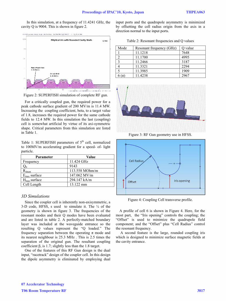
In this simulation, at a frequency of 11.4241 GHz, the cavity Q is 9004. This is shown in figure 2.
Figure 2: SUPERFISH simulation of complete RF gun.
For a critically coupled gun, the required power for a peak cathode surface gradient of 200 MV/m is 11.4 MW. Increasing the coupling coefficient, beta, to a target value of 1.8, increases the required power for the same cathode fields to 12.4 MW. In this simulation the last (coupling) cell is somewhat artificial by virtue of its axi-symmetric shape. Critical parameters from this simulation are listed in Table 1.
Table 1: SUPERFISH parameters of 5th cell, normalized to 100MV/m accelerating gradient for a speed- of- light particle.
Parameter Value Frequency 11.424 GHz Q0 9143 Rshunt 113.558 MOhm/m Emax surface 147.062 MV/m Hmax surface 294.147 kA/m Cell Length 13.122 mm
3D Simulations Since the coupler cell is inherently non-axisymmetric, a
3-D code, HFSS, s used to simulate it. The ¼ of the geometry is shown in figure 3. The frequencies of the resonant modes and their Q modes have been evaluated and are listed in table 2. A perfectly-matched boundary layer was included at the waveguide entrance so the resulting Q values represent the “Q loaded.” The frequency separation between the operating π mode and its nearest neighbour is 25.3 MHz . This is 2.5 times the separation of the original gun. The resultant coupling coefficient β, is 1.7; slightly less than the 1.8 target.
One of the features of this RF Gun design is the dual input, “racetrack” design of the coupler cell. In this design the dipole asymmetry is eliminated by employing dual
input ports and the quadrupole asymmetry is minimized by offsetting the cell radius origin from the axis in a direction normal to the input ports.
Table 2: Resonant frequencies and Q values
Figure 3: RF Gun geometry use in HFSS.
Figure 4: Coupling Cell transverse profile.
A profile of cell 6 is shown in Figure 4. Here, for the
most part, the “Iris opening” controls the coupling; the “Offset” is used to minimize the quadrupole field component; and the “Offset” plus “Cell Radius” control the resonant frequency.
A second feature is the large, rounded coupling iris which is designed to minimize surface magnetic fields at the cavity entrance.
Mode Resonant frequency (GHz) Q value 1 11.1218 7648 2 11.1700 4995 3 11.2466 3187 4 11.3321 2294 5 11.3985 1909 6 (π) 11.4238 2967
Proceedings of IPAC’10, Kyoto, Japan THPEA063
07 Accelerator Technology
T06 Room Temperature RF 3817
Minimizing Quadrupole Field Component In order to find the optimal “Offset” to remove the
quadrupole field component in the coupler cell, a series of simulations were performed in HFSS using different “Offset” values. The coupler cell alone was used in this simulation. Values of the complex magnitude of the electric field were taken at a radius of 3 mm around the axis in the (axial) centre of the cell. This data was Fourier-analysed to determine the multipole components. Results of these calculations, at different Offset values, normalized to the average field, are shown in Figure 5 along with the quadrupole component when no offset is used, i.e. no “racetrack”.
Figure 5: Electric Quadrupole field component at a radius of 3 mm.
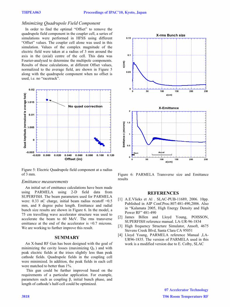
Emittance measurements An initial set of emittance calculations have been made
using PARMELA using 2-D field data from SUPERFISH. The beam parameters used for PARMELA were: 0.33 nC charge, initial beam radius σcutoff =0.5 mm, and 8 degree pulse length. Emittance and radial bunch size results are shown in Figure 6. In the model, a 75 cm travelling wave accelerator structure was used to accelerate the beam to 60 MeV. The rms transverse emittance at the end of the accelerator is ≈0.7 microns. We are working to further improve this result.
SUMMARY An X-band RF Gun has been designed with the goal of
minimizing the cavity losses (maximizing Q0 ) and with peak electric fields at the irises slightly less than peak cathode fields. Quadrupole fields in the coupling cell were minimized. In addition, the peak fields in each cell were matched to better than 1%.
This gun could be further improved based on the requirements of a particular application. For example, parameters such as coupling β, initial bunch phase, and length of cathode’s half-cell could be optimized.
Figure 6: PARMELA Transverse size and Emittance results
REFERENCES [1] A.E.Vlieks et Al . SLAC-PUB-11689, 2006. 10pp.
Published in AIP Conf.Proc.807:481-490,2006. Also in “Kalamata 2005, High Energy Density and High Power RF” 481-490
[2] James Billen and Lloyd Young, POISSON, SUPERFISH reference manual. LA-UR-96-1834
[3] High frequency Structure Simulator, Ansoft, 4675 Stevens Creek Blvd, Santa Clara CA 95051
[4] Lloyd Young, PARMELA reference Manual ,LA-UR96-1835. The version of PARMELA used in this work is a modified version due to E. Colby, SLAC
-0.005
0
0.005
0.01
0.015
0.02
-0.020 0.000 0.020 0.040 0.060 0.080 0.100 0.120Offset (in)
No quad correction
0
0.5
1
1.5
2
0 50 100 150 200 250
X-Emittance
z(cm)
AccelGun
0
0.05
0.1
0.15
0 50 100 150 200 250
X-rms Bunch size
z(cm)
THPEA063 Proceedings of IPAC’10, Kyoto, Japan
3818
07 Accelerator Technology
T06 Room Temperature RF