WS-PRO2 Golf Course Weather Station - Rain Bird · Rain Bird WS-PRO2 Golf Course Weather Station...
72
WS-PRO2 Golf Course Weather Station Installation, Operation, Maintenance, and Troubleshooting Manual April 2014 GT27145G
Transcript of WS-PRO2 Golf Course Weather Station - Rain Bird · Rain Bird WS-PRO2 Golf Course Weather Station...

WS-PRO2 Golf Course Weather Station
Installation, Operation, Maintenance, and
Troubleshooting Manual
April 2014 GT27145G

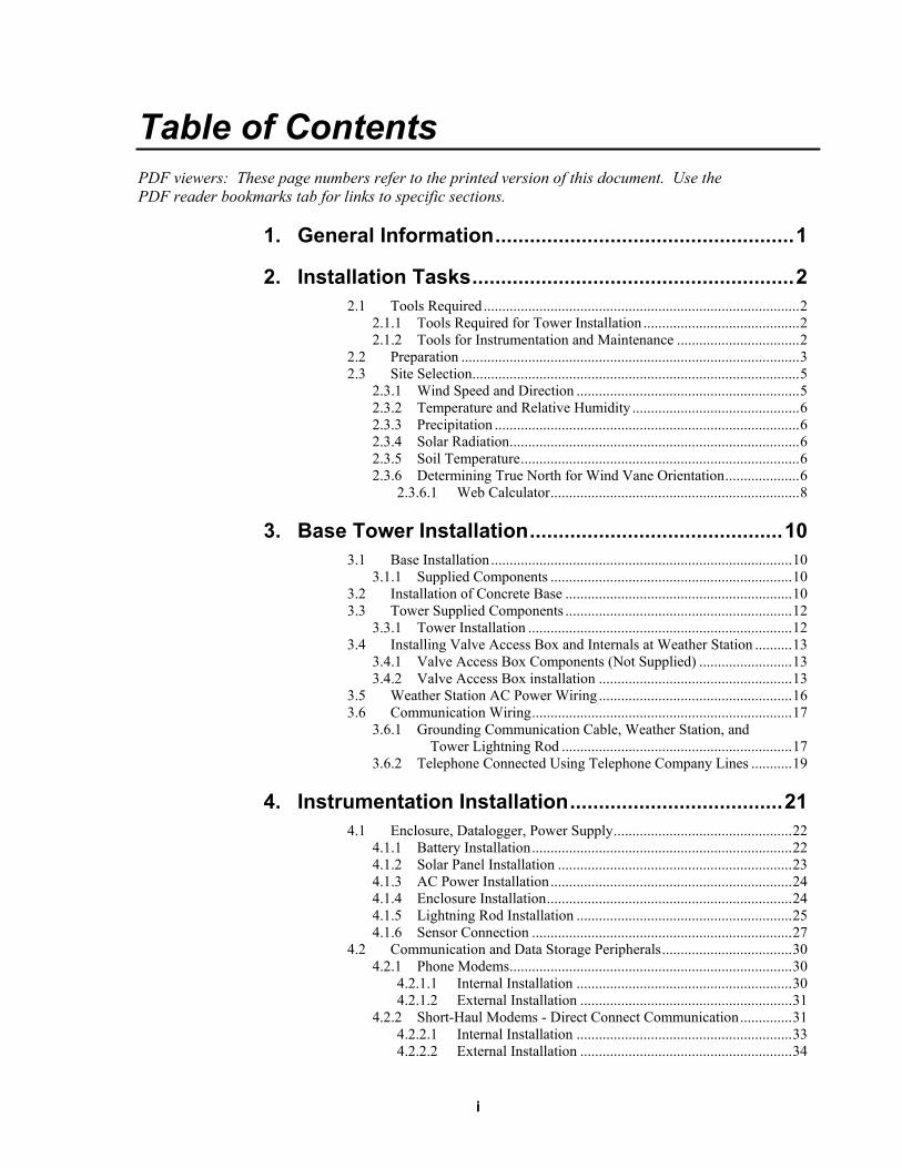
Table of Contents PDF viewers: These page numbers refer to the printed version of this document. Use the PDF reader bookmarks tab for links to specific sections.
1. General Information .................................................... 1
2. Installation Tasks ........................................................ 2
2.1 Tools Required ..................................................................................... 2 2.1.1 Tools Required for Tower Installation .......................................... 2 2.1.2 Tools for Instrumentation and Maintenance ................................. 2
2.2 Preparation ........................................................................................... 3 2.3 Site Selection ........................................................................................ 5
2.3.1 Wind Speed and Direction ............................................................ 5 2.3.2 Temperature and Relative Humidity ............................................. 6 2.3.3 Precipitation .................................................................................. 6 2.3.4 Solar Radiation .............................................................................. 6 2.3.5 Soil Temperature ........................................................................... 6 2.3.6 Determining True North for Wind Vane Orientation .................... 6
2.3.6.1 Web Calculator ................................................................... 8
3. Base Tower Installation ............................................ 10
3.1 Base Installation ................................................................................. 10 3.1.1 Supplied Components ................................................................. 10
3.2 Installation of Concrete Base ............................................................. 10 3.3 Tower Supplied Components ............................................................. 12
3.3.1 Tower Installation ....................................................................... 12 3.4 Installing Valve Access Box and Internals at Weather Station .......... 13
3.4.1 Valve Access Box Components (Not Supplied) ......................... 13 3.4.2 Valve Access Box installation .................................................... 13
3.5 Weather Station AC Power Wiring .................................................... 16 3.6 Communication Wiring ...................................................................... 17
3.6.1 Grounding Communication Cable, Weather Station, and Tower Lightning Rod .............................................................. 17
3.6.2 Telephone Connected Using Telephone Company Lines ........... 19
4. Instrumentation Installation ..................................... 21
4.1 Enclosure, Datalogger, Power Supply ................................................ 22 4.1.1 Battery Installation ...................................................................... 22 4.1.2 Solar Panel Installation ............................................................... 23 4.1.3 AC Power Installation ................................................................. 24 4.1.4 Enclosure Installation .................................................................. 24 4.1.5 Lightning Rod Installation .......................................................... 25 4.1.6 Sensor Connection ...................................................................... 27
4.2 Communication and Data Storage Peripherals ................................... 30 4.2.1 Phone Modems ............................................................................ 30
4.2.1.1 Internal Installation .......................................................... 30 4.2.1.2 External Installation ......................................................... 31
4.2.2 Short-Haul Modems - Direct Connect Communication .............. 31 4.2.2.1 Internal Installation .......................................................... 33 4.2.2.2 External Installation ......................................................... 34
i
Table of Contents
4.2.3 Sealing and Desiccating the Enclosure ....................................... 36
5. Installation of Sensor Arm ....................................... 38
5.1 Components ....................................................................................... 38 5.2 Installation ......................................................................................... 38 5.3 Sensor Connection ............................................................................. 39 5.4 RH and Temperature Radiation Shield .............................................. 39
6. Sensor Installation .................................................... 41
6.1 Wind Sensor ...................................................................................... 41 6.2 Rain Gage Installation ....................................................................... 43 6.3 Pyranometer....................................................................................... 44 6.4 Soil Temperature Sensor (Optional - See Section 2.3.5) ................... 45 6.5 Sensor Schematics ............................................................................. 45
7. Maintenance and Troubleshooting .......................... 48
7.1 Maintenance ...................................................................................... 48 7.1.1 Instrumentation Maintenance ..................................................... 48 7.1.2 Batteries ...................................................................................... 49 7.1.3 Desiccant .................................................................................... 49 7.1.4 Sensor Maintenance ................................................................... 49
7.2 Troubleshooting ................................................................................. 50 7.2.1 No Response Using the CR1000KD Keypad ............................. 50 7.2.2 No Response from Datalogger through SC32B, Rad Modem,
or Phone Modem..................................................................... 51 7.2.3 Unreasonable Results Displayed in Public, T_Hourly,
T_DailyTable .......................................................................... 52
Appendices
A. Grounding Recommendations ............................... A-1
A.1 Grounding System Installation ........................................................ A-1 A.1.1 Ground Resistance .................................................................... A-1 A.1.2 Installation Requirement .......................................................... A-1 A.1.3 Ground Rod Stacking ............................................................... A-2
A.2 Grounding System Designs ............................................................. A-3 A.2.1 Design “Y” ............................................................................... A-3 A.2.2 Design “Y” (Alternate) ............................................................. A-4 A.2.3 Grounding Plate Design ........................................................... A-6
B. Exploded Views ....................................................... B-1
B.1 Enclosure ......................................................................................... B-1 B.2 Crossarm .......................................................................................... B-2
C. Maintenance Records ............................................. C-1
ii
Table of Contents
Figures 2-1. Shipping box packaging ....................................................................... 3 2-2. WS-PRO2 Weather Station, top layer .................................................. 4 2-3. WS-PRO2 Weather Station .................................................................. 4 2-4. Effect of structure on wind flow........................................................... 5 2-5. Magnetic declination for the contiguous United States (2004) ............ 7 2-6. Declination angles east of True North are subtracted from 0 to get
True North ........................................................................................ 8 2-7. Declination angles west of True North are added to 0 to get True
North ................................................................................................. 8 3-1. WS-PRO2 tower installation .............................................................. 10 3-2. WS-PRO2 tower base installation ...................................................... 11 3-3. Cut-away view shows anchor bolt and conduit placement in cement
pad .................................................................................................. 13 3-4. WS-PRO2 Weather Station sweep, base detail, and anchor detail ..... 14 3-5. WS-PRO2 Weather Station grounding assembly and all wiring ........ 15 3-6. Weather station base detail for direct connect communication .......... 18 3-7. Weather station base detail for phone modem communication .......... 20 4-1. Instrumentation mounted on tower..................................................... 21 4-2. PS100 battery installation................................................................... 22 4-3. PS100 to enclosure wiring .................................................................. 22 4-4. Solar panel mounting and cabling ...................................................... 23 4-5. Enclosure spacing above pole ............................................................ 24 4-6. Lightning rod bracket installation ...................................................... 25 4-7. Grounding to lightning rod clamp ...................................................... 26 4-8. Position of sensor bulkhead connectors ............................................. 27 4-9. Connecting sensor cabling to enclosure ............................................. 28 4-10. Cabling straps to wire tie harness ....................................................... 29 4-11. Connector cover in place and lightning rod ....................................... 29 4-12. Phone modem mounting and connection (battery not shown) ........... 30 4-13. Short-haul modem mounting and connection ..................................... 32 4-14. Closer view of short-haul modem mounting and connection ............. 33 4-15. Short-haul model wiring diagram....................................................... 36 4-16. Desiccant installation ......................................................................... 37 5-1. Sensor arm mounting ......................................................................... 38 5-2. Temp/relative humidity sensor with yellow cap ................................ 39 5-3. Temperature/relative humidity sensor without yellow protective
cap .................................................................................................. 40 5-4. Attaching gill radiation shield to temp/relative humidity sensor ........ 40 6-1. Wind and RH/temp sensor installation ............................................... 41 6-2. 034B mounting to pipe ....................................................................... 42 6-3. Remove rubber band from tipping mechanism .................................. 43 6-4. Pyranometer leveling ......................................................................... 44 6-5. REMOVE red or green pyranometer cap ........................................... 44 6-6. Schematic of RH and temperature probe and connector temp/RH ..... 45 6-7. Schematic of wind speed and direction probe and connector
WS/WD .......................................................................................... 46 6-8. Schematic of solar radiation sensor and connector solar radiation ..... 47 6-9. Schematic of rain sensor and connector rain (precip) ........................ 48 A-1. Grounding systems can develop resistance at many points ............. A-2 A-2. Stacking groundings rods with threaded couplers can help
decrease ground resistance .......................................................... A-3 A-3. Design “Y” uses three groundings rods installed in radial 120
degrees “Y-shaped” configuration ............................................... A-3
iii
Table of Contents
A-4. Grounding system “Y can be installed as shown, or with ground enhancement material to reduce ground resistance even further.. A-4
A-5. Design “Y” (alternate) uses nine copper-clad grounding rods installed in a 120 degree star configuration ................................. A-5
A-6. The alternate version of grounding design “Y” uses nine grounding rods to reduce ground resistance ................................. A-5
A-7. The” Grounding Plate” design uses one copper-clad grounding rod and a rectangular copper grounding plate .............................. A-6
A-8. The “Grounding Plate” design may be used with or without ground enhancement material, depending on side conditions ...... A-6
iv
Rain Bird WS-PRO2 Golf Course Weather Station 1. General Information
The Rain Bird WS-PRO2 Weather Station, when used in conjunction with the Rain Bird Cirrus, Nimbus II, or Stratus II Central Control system, provides the irrigation professional with a powerful tool to aid in the growing of lush, healthy, green turf grass, while conserving important resources, such as water, power, etc.
Rain Bird Smart Weather software interrogates the WS-PRO2 weather station to retrieve information that has been gathered on a daily basis of the climatic conditions that affect the irrigation application for the area.
The Smart Weather software subjects the climatic information that it gathers to a version of the modified Penman Equation. The Penman Equation has been proven through over 35 years of university research to be one of the most reliable predictors of turf grass water use requirements.
The weather station monitors the following climatic conditions:
• Rainfall • Wind speed and direction • Air temperature • Relative humidity • Solar radiation
The standard WS-PRO2 configuration includes sensors to monitor these conditions, a datalogger to capture this data, a modem to communicate the information to the Smart Weather software located on the central control computer, and a power supply.
The Rain Bird Model “PRO 2” Weather Station is available in four (4) basic configurations:
Model WSPRO2SH - A direct wire system intended for use when the weather station is within 20,000 feet of the central control computer and communication is via a wire path between the weather station and the computer. A separate power source is required for this weather station.
Model WSPRO2PH - A phone modem system for use when the weather station is further than 20,000 feet from the central control computer or when they cannot be connected by a communication wire path. The system communicates utilizing a standard, dedicated phone service. A separate power source is required for this weather station.
Model WSPRO2SHS – A direct wire system intended for use when the weather station is within 20,000 feet of the central control computer and communication is via a wire path between the weather station and the computer. This weather station utilized solar power instead of a local power source.
Model WSPRO2PHS - A phone modem system for use when the weather station is further than 20,000 feet from the central control computer or when they cannot be connected by a communication wire path. The system
1
Rain Bird WS-PRO2 Golf Course Weather Station
communicates utilizing a standard, dedicated phone service. This weather station utilized solar power instead of a local power source.
2. Installation Tasks 2.1 Tools Required
The tools required for weather station installation are listed below.
2.1.1 Tools Required for Tower Installation ET tower Shovel Rake Open end wrenches: 3/8", 7/16", 1/2", (2) 9/16", 15/16” Magnetic compass 6' Step ladder Tape measure (12’ to 20’) Claw hammer Level (24” to 36”) Hand saw Materials for concrete form:
(4) 1" x 2" x 12" stakes (2) 2" x 4" x 96" lumber (12) 8p double-head nails (8) 16p double-head nails 20 ft form wire 1/2 Yard concrete Concrete trowel, edger Electrical fish tape or 20 feet of small diameter rope Wheelbarrow
2.1.2 Tools for Instrumentation and Maintenance ET tower Lock and key for enclosure Magnetic declination angle (4, Instrumentation Installation) Magnetic compass Straight bit screwdrivers (small, medium, large) Phillips-head screwdrivers (small, medium) Small diagonal side-cutters Needle-nose pliers Wire strippers Pocket knife Calculator Volt / ohm meter Electrical tape Step ladder (6') Station manuals Station log and pen Open end wrenches: 3/8", 7/16", 1/2", (2) 9/16", 15/16” Socket wrench and 7/16" deep well socket Adjustable wrench Pliers Conduit and associated tools (as required) Felt-tipped marking pen Claw hammer Pipe wrench (12")
2
Rain Bird WS-PRO2 Golf Course Weather Station
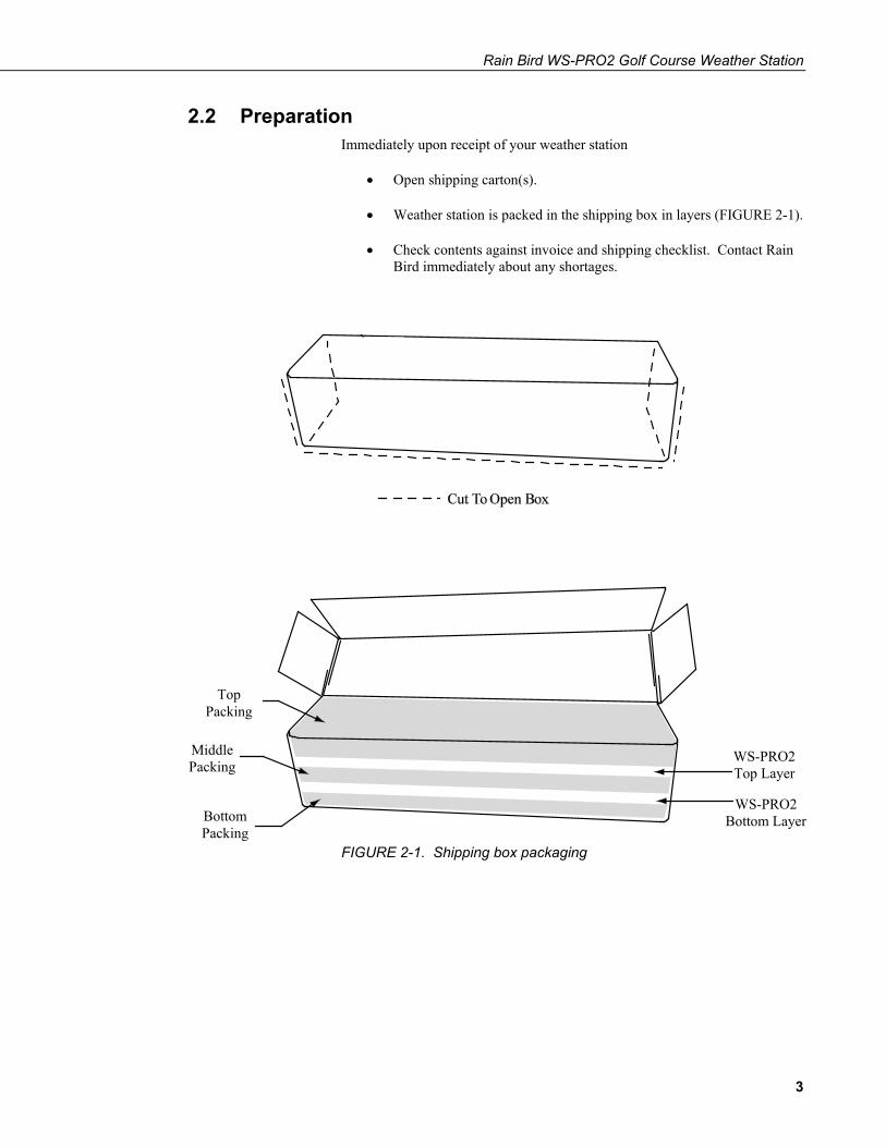
2.2 Preparation Immediately upon receipt of your weather station
• Open shipping carton(s).
• Weather station is packed in the shipping box in layers (FIGURE 2-1).
• Check contents against invoice and shipping checklist. Contact Rain Bird immediately about any shortages.
FIGURE 2-1. Shipping box packaging
Top Packing
Middle Packing
Bottom Packing
WS-PRO2 Top Layer
WS-PRO2 Bottom Layer
3

Rain Bird WS-PRO2 Golf Course Weather Station
FIGURE 2-2. WS-PRO2 Weather Station, top layer
FIGURE 2-3. WS-PRO2 Weather Station
Top Layer
Bottom Layer
4
Rain Bird WS-PRO2 Golf Course Weather Station
2.3 Site Selection Selecting an appropriate site for the weather station is critical in order to obtain accurate meteorological data. In general, the site should be representative of the general area of interest and away from the influence of obstructions such as buildings and trees.
The weather station should not be located where sprinkler irrigation water will strike sensors or instrument enclosure.
Some general guidelines for site selection are listed below, which were condensed from EPA (1988)1, WMO (1983)2, and AASC (1985)3 publications.
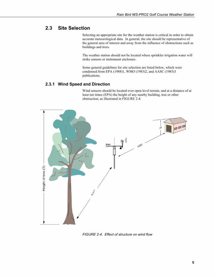
2.3.1 Wind Speed and Direction Wind sensors should be located over open level terrain, and at a distance of at least ten times (EPA) the height of any nearby building, tree or other obstruction, as illustrated in FIGURE 2-4.
FIGURE 2-4. Effect of structure on wind flow
5
Rain Bird WS-PRO2 Golf Course Weather Station
2.3.2 Temperature and Relative Humidity Sensors should be located over an open level area at least 9 m (EPA) in diameter. The surface should be covered by short grass, or where grass does not grow, the natural earth surface. Sensors should be located at a distance of at least four times the height of any nearby obstruction and at least 30 m (EPA) from large paved areas. Sensors should be protected from thermal radiation, and adequately ventilated.
Situations to avoid include:
• Large industrial heat sources • Rooftops • Steep slopes • Sheltered hollows • High vegetation • Shaded areas • Swamps • Areas where snow drifts occur • Low places holding standing water after rains
2.3.3 Precipitation A rain gage should be sited on level ground that is covered with short grass or gravel. In open areas, the distance to obstructions should be two to four times (EPA, AASC) the height of the obstruction.
2.3.4 Solar Radiation Pyranometers should be located to avoid shadows on the sensor at any time. Mounting it on the southernmost (northern hemisphere) portion of the weather station will minimize the chance of shading from other weather station structures. Reflective surfaces and sources of artificial radiation should be avoided.
2.3.5 Soil Temperature The Rain Bird WS-PRO2 weather station does not come standard equipped for measurement of soil temperature, and is not compatible with the Smart Weather software. The measurement site for soil temperature should be at least 1 m2 and typical of the surface of interest. The ground surface should be level with respect to the immediate area (10 m radius).
Standard measurement depths: 10.0 cm ± 1.0 cm (AASC) 5.0 cm, 10.0 cm, 50.0 cm, 100.0 cm (WMO)
2.3.6 Determining True North for Wind Vane Orientation Magnetic declination, or other methods to find True North, should be determined prior to installing the weather station. True North is usually found by reading a magnetic compass and applying the correction for magnetic declination*; where magnetic declination is the number of degrees between True North and Magnetic North. The preferred method to obtain magnetic declination for a specific site is to use a web calculator offered by NOAA (Section 2.3.6.1). The magnetic declination
6

Rain Bird WS-PRO2 Golf Course Weather Station
can also be obtained from a map or local airport. A general map showing magnetic declination for the contiguous United States is shown in FIGURE 2-5.
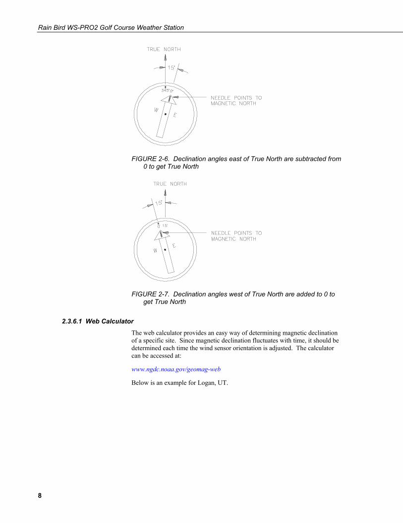
Declination angles east of True North are considered negative, and are subtracted from 0 degrees to get True North as shown FIGURE 2-6. Declination angles west of True North are considered positive, and are added to 0 degrees to get True North as shown in FIGURE 2-7. For example, the declination for Logan, Utah is 12.4° East. True North is 360° - 12.4°, or 347.6° as read on a compass.
* Other methods employ observations using the North Star or the sun, and are discussed in the Quality Assurance Handbook for Air Pollution Measurement Systems, Volume IV - Meteorological Measurements4.
FIGURE 2-5. Magnetic declination for the contiguous United States (2004)
7
Rain Bird WS-PRO2 Golf Course Weather Station
FIGURE 2-6. Declination angles east of True North are subtracted from 0 to get True North
FIGURE 2-7. Declination angles west of True North are added to 0 to get True North
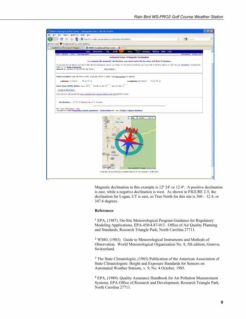
2.3.6.1 Web Calculator The web calculator provides an easy way of determining magnetic declination of a specific site. Since magnetic declination fluctuates with time, it should be determined each time the wind sensor orientation is adjusted. The calculator can be accessed at:
www.ngdc.noaa.gov/geomag-web
Below is an example for Logan, UT.
8
Rain Bird WS-PRO2 Golf Course Weather Station
Magnetic declination in this example is 12º 24′ or 12.4º. A positive declination is east, while a negative declination is west. As shown in FIGURE 2-5, the declination for Logan, UT is east, so True North for this site is 360 – 12.4, or 347.6 degrees.
References
1 EPA, (1987). On-Site Meteorological Program Guidance for Regulatory Modeling Applications, EPA-450/4-87-013. Office of Air Quality Planning and Standards, Research Triangle Park, North Carolina 27711.
2 WMO, (1983). Guide to Meteorological Instruments and Methods of Observation. World Meteorological Organization No. 8, 5th edition, Geneva, Switzerland.
3 The State Climatologist, (1985) Publication of the American Association of State Climatologists: Height and Exposure Standards for Sensors on Automated Weather Stations, v. 9, No. 4 October, 1985.
4 EPA, (1989). Quality Assurance Handbook for Air Pollution Measurement Systems, EPA Office of Research and Development, Research Triangle Park, North Carolina 27711.
9
Rain Bird WS-PRO2 Golf Course Weather Station
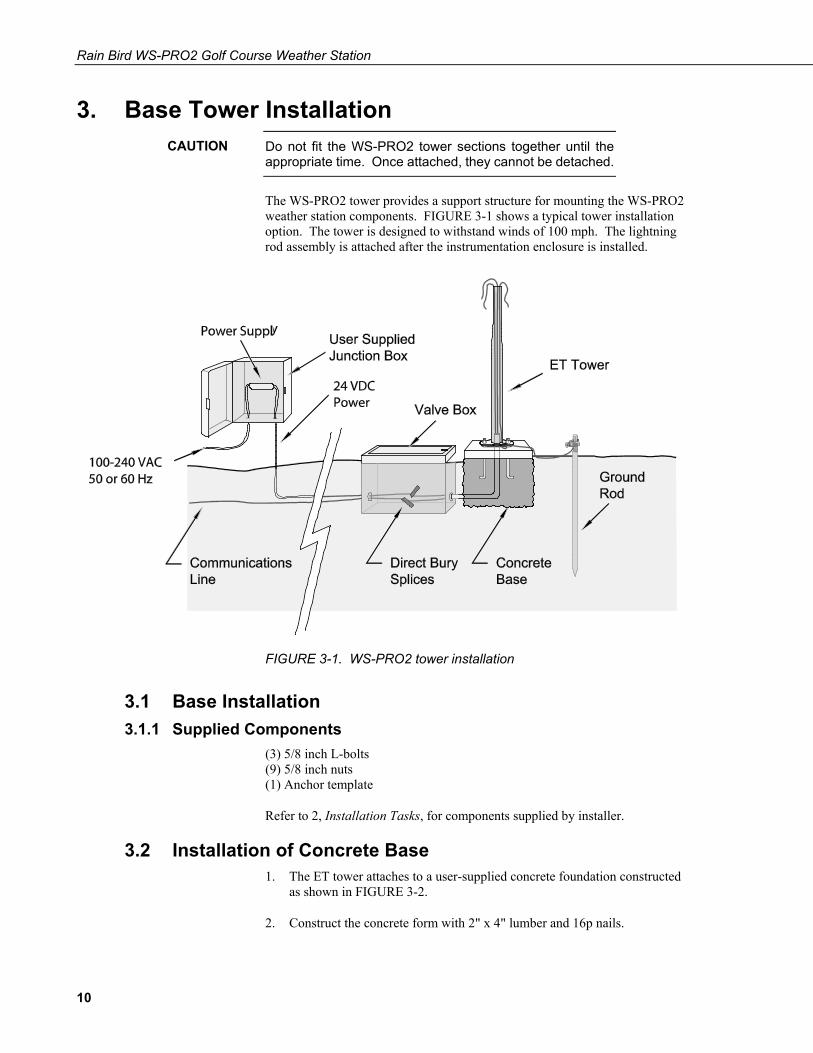
3. Base Tower Installation Do not fit the WS-PRO2 tower sections together until the appropriate time. Once attached, they cannot be detached.
The WS-PRO2 tower provides a support structure for mounting the WS-PRO2 weather station components. FIGURE 3-1 shows a typical tower installation option. The tower is designed to withstand winds of 100 mph. The lightning rod assembly is attached after the instrumentation enclosure is installed.
FIGURE 3-1. WS-PRO2 tower installation
3.1 Base Installation 3.1.1 Supplied Components
(3) 5/8 inch L-bolts (9) 5/8 inch nuts (1) Anchor template
Refer to 2, Installation Tasks, for components supplied by installer.
3.2 Installation of Concrete Base 1. The ET tower attaches to a user-supplied concrete foundation constructed
as shown in FIGURE 3-2.
2. Construct the concrete form with 2" x 4" lumber and 16p nails.
CAUTION
10
Rain Bird WS-PRO2 Golf Course Weather Station
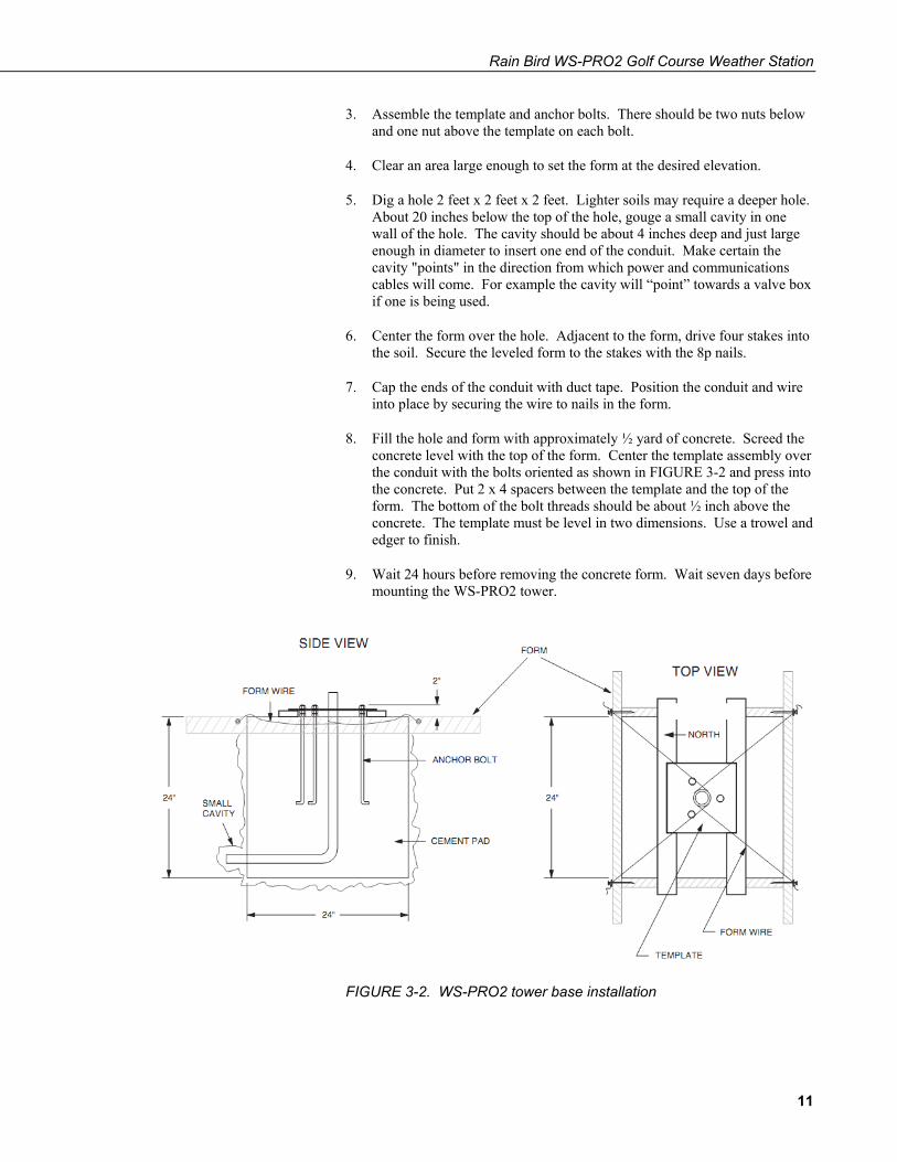
3. Assemble the template and anchor bolts. There should be two nuts below and one nut above the template on each bolt.
4. Clear an area large enough to set the form at the desired elevation.
5. Dig a hole 2 feet x 2 feet x 2 feet. Lighter soils may require a deeper hole. About 20 inches below the top of the hole, gouge a small cavity in one wall of the hole. The cavity should be about 4 inches deep and just large enough in diameter to insert one end of the conduit. Make certain the cavity "points" in the direction from which power and communications cables will come. For example the cavity will “point” towards a valve box if one is being used.
6. Center the form over the hole. Adjacent to the form, drive four stakes into the soil. Secure the leveled form to the stakes with the 8p nails.
7. Cap the ends of the conduit with duct tape. Position the conduit and wire into place by securing the wire to nails in the form.
8. Fill the hole and form with approximately ½ yard of concrete. Screed the concrete level with the top of the form. Center the template assembly over the conduit with the bolts oriented as shown in FIGURE 3-2 and press into the concrete. Put 2 x 4 spacers between the template and the top of the form. The bottom of the bolt threads should be about ½ inch above the concrete. The template must be level in two dimensions. Use a trowel and edger to finish.
9. Wait 24 hours before removing the concrete form. Wait seven days before mounting the WS-PRO2 tower.
FIGURE 3-2. WS-PRO2 tower base installation
11

Rain Bird WS-PRO2 Golf Course Weather Station
3.3 Tower Supplied Components (1) Upper tower section (tapered) (1) Lower tower section (6) 5/8-inch washers (1) 12-foot 10 AWG ground cable (1) 20-foot 4-wire patch cable for communications (1) 20-foot power cable
3.3.1 Tower Installation Attach the tower to the base as shown in FIGURE 3-3 and FIGURE 3-4.
1. Dig a hole close to the concrete base to access the lower conduit opening. From the hole, trench to the power and communications sources. Remove the duct tape from both ends of the conduit.
2. Remove the template. Attach the two pieces of the tower. This is a permanent connection and cannot be undone. Lay the tower on the ground with the base next to the concrete foundation.
3. Thread communications and power cables through the tower and conduit. Electrical fish tape will help.
4. Cut and save a 9-inch piece of 10 AWG ground wire from the 12 foot length provided. Thread the remaining 11 foot ground wire through the tower. Secure all wiring so it does not slip back into the tower or conduit.
5. Raise the tower on a still day. Place a washer on top of the two nuts on each foundation bolt. Taking great care not to damage cables between the tower and conduit, raise the tower and lower it onto the conduit and mounting bolts. Install a washer and nut on each bolt and hand tighten. Check plumb of the tower by placing a level on the north and east sides of the lower tower section. Adjust the topmost of the two lower nuts (leveling nut) on each bolt as necessary. When plumb is established, lock the leveling nut in place by tightening the lowest nut against it. Tighten the three top nuts with the wrench.
12
Rain Bird WS-PRO2 Golf Course Weather Station
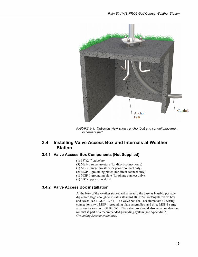
FIGURE 3-3. Cut-away view shows anchor bolt and conduit placement in cement pad
3.4 Installing Valve Access Box and Internals at Weather Station
3.4.1 Valve Access Box Components (Not Supplied) (1) 18”x24” valve box (3) MSP-1 surge arrestors (for direct connect only) (1) MSP-1 surge arrestor (for phone connect only) (2) MGP-1 grounding plates (for direct connect only) (1) MGP-1 grounding plate (for phone connect only) (1) 5/8” copper ground rod
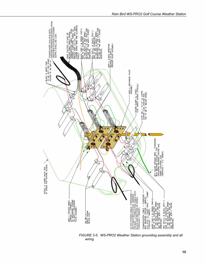
3.4.2 Valve Access Box installation At the base of the weather station and as near to the base as feasibly possible, dig a hole large enough to install a standard 18” x 24” rectangular valve box and cover (see FIGURE 3-4). The valve box shall accommodate all wiring connections, two MGP-1 grounding plate assemblies, and three MSP-1 surge arrestors as seen in FIGURE 3-5. The valve box should also accommodate one rod that is part of a recommended grounding system (see Appendix A, Grounding Recommendations).
13
Rain Bird WS-PRO2 Golf Course Weather Station
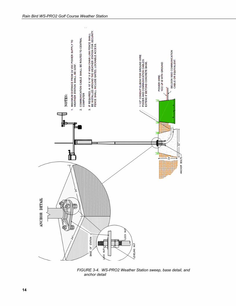
FIGURE 3-4. WS-PRO2 Weather Station sweep, base detail, and anchor detail
14
Rain Bird WS-PRO2 Golf Course Weather Station
FIGURE 3-5. WS-PRO2 Weather Station grounding assembly and all wiring
POW
ER W
IRE
10/2
UF-
B W
ITH
G
RO
UN
D M
AXIM
UM
DIS
TAN
CE
FRO
M
WEA
THER
STA
TIO
N T
O P
OW
ER
SUPP
LY S
HAL
L BE
3,2
50’.
24 V
DC
PO
WER
CAB
LE -
FUR
NIS
HED
W
ITH
WEA
THER
STA
TIO
N -
MAR
KED
P/
N 9
922
– 2
CO
ND
UC
TOR
CAB
LE W
ITH
BL
ACK
AND
RED
PAI
R O
F W
IRES
. (T
HR
OU
GH
1” S
WEE
P)
15
Rain Bird WS-PRO2 Golf Course Weather Station
3.5 Weather Station AC Power Wiring Furnished as part of the weather station, is a 100-240 VAC to 24 VDC step-down power supply. This power supply must be installed in a weather-proof location such as a local satellite controller pedestal or other protected location.
Connect the AC in power wires of the power supply to a 100-240 VAC power source that is properly labeled for future reference. Connect a pair of UF power wires, of proper size, to the DC out wires of the power supply. The power wires shall be direct buried to the weather station.
Connect the 24 VDC power wires to the “Red” and “Black” wires of the “FIELD” side of an MSP-1 surge arrestor, which shall be mounted in an MGP-1 grounding plate assembly near the weather station. The MGP-1 grounding plate assembly shall be securely mounted on a 5/8” diameter copper-clad, ground rod — one of a recommended grounding system (see Appendix A, Grounding Recommendations). See FIGURE 3-5 and FIGURE 3-6.
The “EQUIPMENT’ side of this MSP-1 surge arrestor shall be connected to “red” and “black” wires of the 20’ power wire cable furnished with the weather station. This cable shall be routed through the 1 ½” diameter long sweep elbow to the base of the weather station, up through the tower, and connected to the “Power” connector in the back of the weather station enclosure. All wire connections and splices in the power wiring shall be made using 3-M DBY or equivalent direct burial connectors. The splice and wire nuts must be completely immersed into the silicon gel inside the splice tube to be waterproof.
Voltage supplied to the power supply shall be 100 to 240 VAC, 50 to 60 Hz.
Wire sizing shall be in accordance with the chart given below. Wire shall be Type “UF” (underground feeder cable) with PVC insulation. The 24 VDC power is used to provide constant charging of the battery within the weather station, through the battery charging circuit.
POWER WIRE SIZING CHART
WIRE SIZE DISTANCE (feet*)
18 500
16 800
14 1275
12 2000
10 3250
8 5100
*Transformer to Weather Station
NOTE
16
Rain Bird WS-PRO2 Golf Course Weather Station
3.6 Communication Wiring 3.6.1 Grounding Communication Cable, Weather Station, and Tower
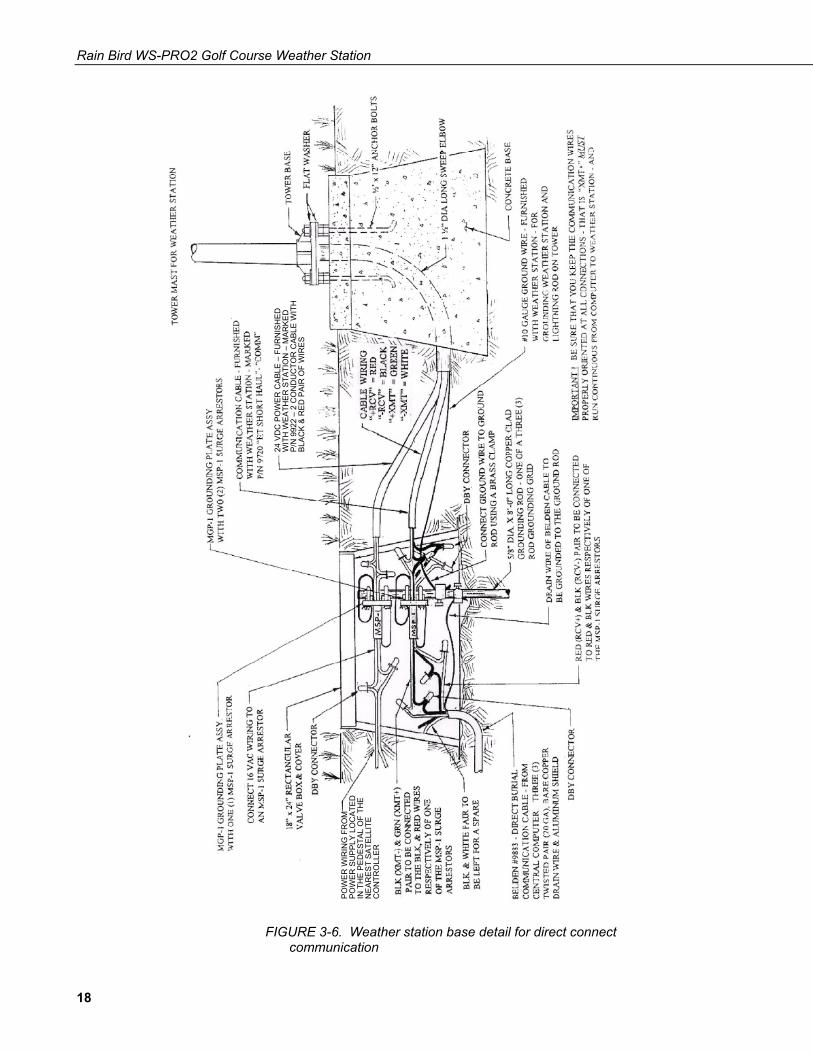
Lightning Rod 1. To ground the communication cable, the bare copper drain wires of the
Belden cable shall be connected to the weather station ground rod using a ground clamp, or using the available screw terminals on the Maxi Ground Plate (MGP-1) assembly.
2. To ground the weather station enclosure and tower lightning rod, see Section 4.1.5, Lightning Rod Installation.
When completing the installation of the communication cable at the central ground grid location, DO NOT connect the drain wire to ground. Leave the drain wire disconnected.
IMPORTANT
17
Rain Bird WS-PRO2 Golf Course Weather Station
FIGURE 3-6. Weather station base detail for direct connect communication
POW
ER W
IRIN
G F
RO
M
POW
ER S
UPP
LY L
OC
ATED
IN
TH
E PE
DES
TAL
OF
THE
NEA
RES
T SA
TELL
ITE
CO
NTR
OLL
ER
24 V
DC
PO
WER
CAB
LE –
FU
RN
ISH
ED
WIT
H W
EATH
ER S
TATI
ON
– M
ARKE
D
P/N
992
2 –
2 C
ON
DU
CTO
R C
ABLE
WIT
H
BLAC
K &
RED
PAI
R O
F W
IRES
18

Rain Bird WS-PRO2 Golf Course Weather Station
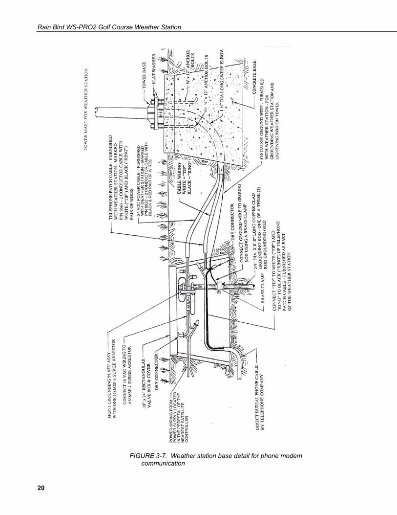
3.6.2 Telephone Connected Using Telephone Company Lines The telephone company needs to run a direct burial telephone cable to the weather station and terminate it near the base of the weather station. This needs to be a modem quality type telephone line with a separate call number.
The “TIP” line of the telephone cable shall be connected to the WHITE (“TIP”) wire of a 20' telephone patch cable, furnished as part of the weather station, marked - 2 conductor cable with WHITE (“TIP”) and BLACK (“RING”) pair of wires. The “RING” line of the telephone cable shall be connected to the BLACK (“RING”) wire of the telephone patch cable. Splices shall be made using 3-M DBY Direct Burial connectors. The splices for the phone line shall be made in the valve box, where the power wiring splices are made and where the MGP-1 grounding plate assembly with an MSP-1 surge arrestor mounted in it, is attached to one rod of a 3-rod grounding grid. Refer to FIGURE 3-7.
This telephone patch cable shall be routed through the 1 ½” diameter long sweep elbow to the base of the weather station.
19
Rain Bird WS-PRO2 Golf Course Weather Station
FIGURE 3-7. Weather station base detail for phone modem communication
POW
ER W
IRIN
G F
RO
M
POW
ER S
UPP
LY L
OC
ATED
IN
TH
E PE
DES
TAL
OF
THE
NEA
RES
T SA
TELL
ITE
CO
NTR
OLL
ER
24 V
DC
PO
WER
CAB
LE –
FU
RN
ISH
ED
WIT
H W
EATH
ER S
TATI
ON
– M
ARKE
D
P/N
992
2 –
2 C
ON
DU
CTO
R C
ABLE
WIT
H
BLAC
K &
RED
PAI
R O
F W
IRES
20
Rain Bird WS-PRO2 Golf Course Weather Station
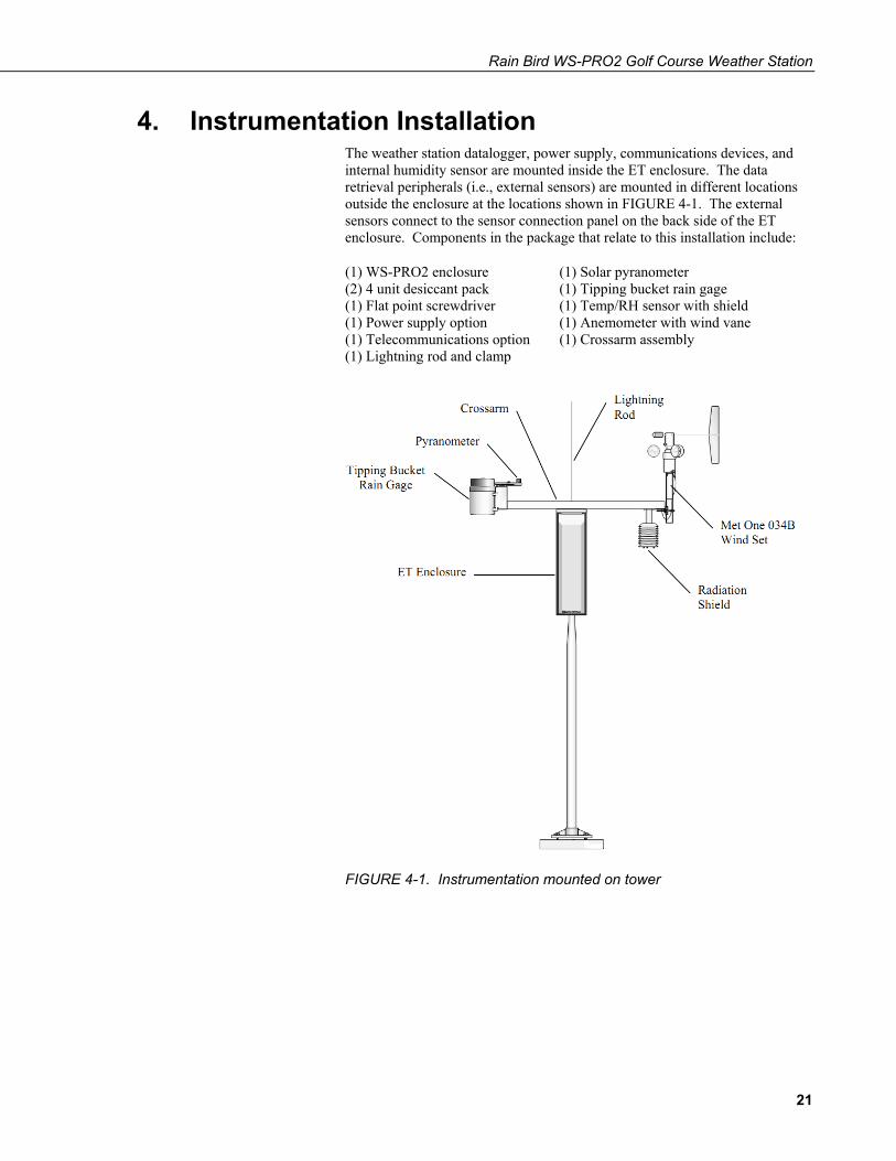
4. Instrumentation Installation The weather station datalogger, power supply, communications devices, and internal humidity sensor are mounted inside the ET enclosure. The data retrieval peripherals (i.e., external sensors) are mounted in different locations outside the enclosure at the locations shown in FIGURE 4-1. The external sensors connect to the sensor connection panel on the back side of the ET enclosure. Components in the package that relate to this installation include:
(1) WS-PRO2 enclosure (1) Solar pyranometer (2) 4 unit desiccant pack (1) Tipping bucket rain gage (1) Flat point screwdriver (1) Temp/RH sensor with shield (1) Power supply option (1) Anemometer with wind vane (1) Telecommunications option (1) Crossarm assembly (1) Lightning rod and clamp
FIGURE 4-1. Instrumentation mounted on tower
21
Rain Bird WS-PRO2 Golf Course Weather Station
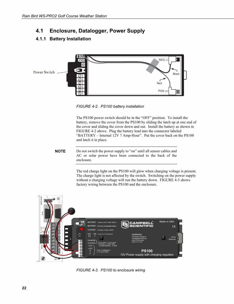
4.1 Enclosure, Datalogger, Power Supply 4.1.1 Battery Installation
FIGURE 4-2. PS100 battery installation
The PS100 power switch should be in the “OFF” position. To install the battery, remove the cover from the PS100 by sliding the latch up at one end of the cover and sliding the cover down and out. Install the battery as shown in FIGURE 4-2 above. Plug the battery lead into the connector labeled “BATTERY – Internal 12V 7 Amp-Hour”. Put the cover back on the PS100 and latch it in place.
Do not switch the power supply to “on” until all sensor cables and AC or solar power have been connected to the back of the enclosure.
The red charge light on the PS100 will glow when charging voltage is present. The charge light is not affected by the switch. Switching on the power supply without a charging voltage will run the battery down. FIGURE 4-3 shows factory wiring between the PS100 and the enclosure.
FIGURE 4-3. PS100 to enclosure wiring
NOTE
22
Rain Bird WS-PRO2 Golf Course Weather Station
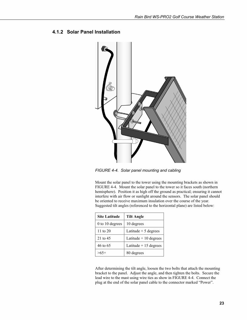
4.1.2 Solar Panel Installation
FIGURE 4-4. Solar panel mounting and cabling
Mount the solar panel to the tower using the mounting brackets as shown in FIGURE 4-4. Mount the solar panel to the tower so it faces south (northern hemisphere). Position it as high off the ground as practical; ensuring it cannot interfere with air flow or sunlight around the sensors. The solar panel should be oriented to receive maximum insulation over the course of the year. Suggested tilt angles (referenced to the horizontal plane) are listed below:
Site Latitude Tilt Angle
0 to 10 degrees 10 degrees
11 to 20 Latitude + 5 degrees
21 to 45 Latitude + 10 degrees
46 to 65 Latitude + 15 degrees
>65+ 80 degrees
After determining the tilt angle, loosen the two bolts that attach the mounting bracket to the panel. Adjust the angle, and then tighten the bolts. Secure the lead wire to the mast using wire ties as show in FIGURE 4-4. Connect the plug at the end of the solar panel cable to the connector marked “Power”.
23
Rain Bird WS-PRO2 Golf Course Weather Station
Make sure the plug is fully seated and the locking ring turned clockwise until it stops.
4.1.3 AC Power Installation See Section 3.5, Weather Station AC Power Wiring.
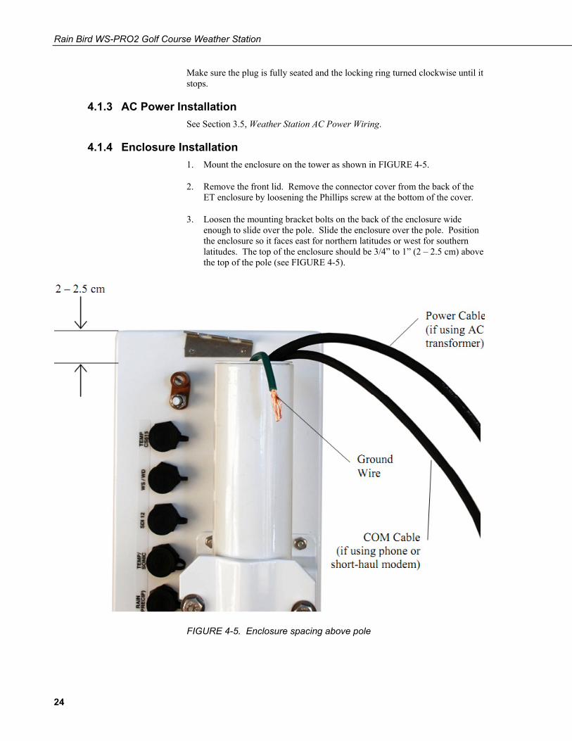
4.1.4 Enclosure Installation 1. Mount the enclosure on the tower as shown in FIGURE 4-5.
2. Remove the front lid. Remove the connector cover from the back of the ET enclosure by loosening the Phillips screw at the bottom of the cover.
3. Loosen the mounting bracket bolts on the back of the enclosure wide enough to slide over the pole. Slide the enclosure over the pole. Position the enclosure so it faces east for northern latitudes or west for southern latitudes. The top of the enclosure should be 3/4” to 1” (2 – 2.5 cm) above the top of the pole (see FIGURE 4-5).
FIGURE 4-5. Enclosure spacing above pole
24
Rain Bird WS-PRO2 Golf Course Weather Station
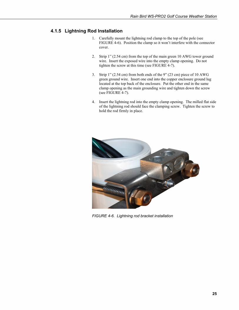
4.1.5 Lightning Rod Installation 1. Carefully mount the lightning rod clamp to the top of the pole (see
FIGURE 4-6). Position the clamp so it won’t interfere with the connector cover.
2. Strip 1” (2.54 cm) from the top of the main green 10 AWG tower ground wire. Insert the exposed wire into the empty clamp opening. Do not tighten the screw at this time (see FIGURE 4-7).
3. Strip 1” (2.54 cm) from both ends of the 9” (23 cm) piece of 10 AWG green ground wire. Insert one end into the copper enclosure ground lug located at the top back of the enclosure. Put the other end in the same clamp opening as the main grounding wire and tighten down the screw (see FIGURE 4-7).
4. Insert the lightning rod into the empty clamp opening. The milled flat side of the lightning rod should face the clamping screw. Tighten the screw to hold the rod firmly in place.
FIGURE 4-6. Lightning rod bracket installation
25

Rain Bird WS-PRO2 Golf Course Weather Station
FIGURE 4-7. Grounding to lightning rod clamp
26
Rain Bird WS-PRO2 Golf Course Weather Station
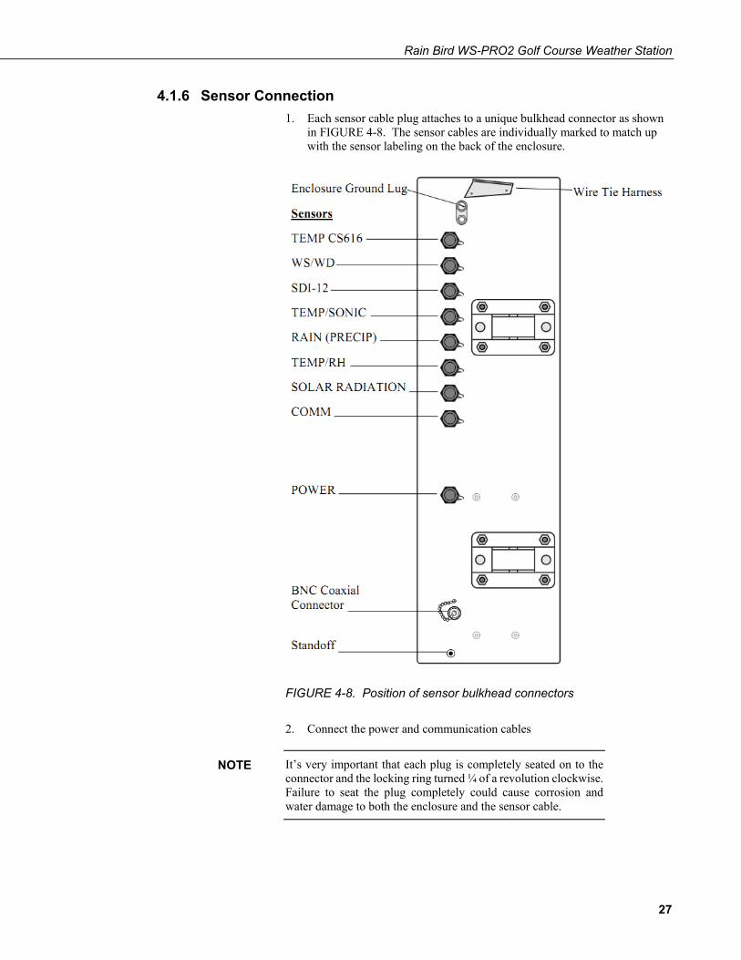
4.1.6 Sensor Connection 1. Each sensor cable plug attaches to a unique bulkhead connector as shown
in FIGURE 4-8. The sensor cables are individually marked to match up with the sensor labeling on the back of the enclosure.
FIGURE 4-8. Position of sensor bulkhead connectors
2. Connect the power and communication cables
It’s very important that each plug is completely seated on to the connector and the locking ring turned ¼ of a revolution clockwise. Failure to seat the plug completely could cause corrosion and water damage to both the enclosure and the sensor cable.
NOTE
27
Rain Bird WS-PRO2 Golf Course Weather Station
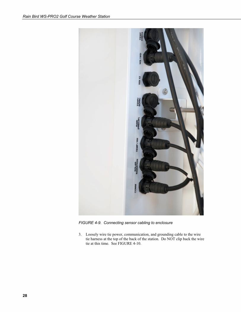
FIGURE 4-9. Connecting sensor cabling to enclosure
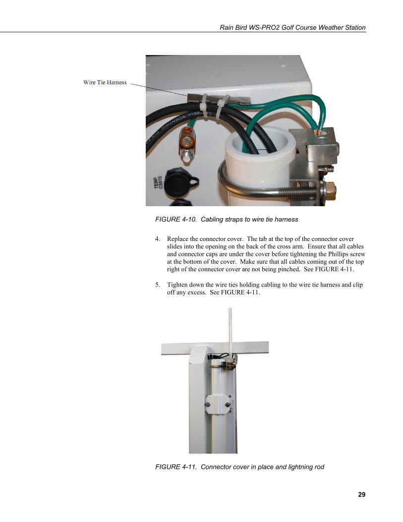
3. Loosely wire tie power, communication, and grounding cable to the wire tie harness at the top of the back of the station. Do NOT clip back the wire tie at this time. See FIGURE 4-10.
28
Rain Bird WS-PRO2 Golf Course Weather Station
FIGURE 4-10. Cabling straps to wire tie harness
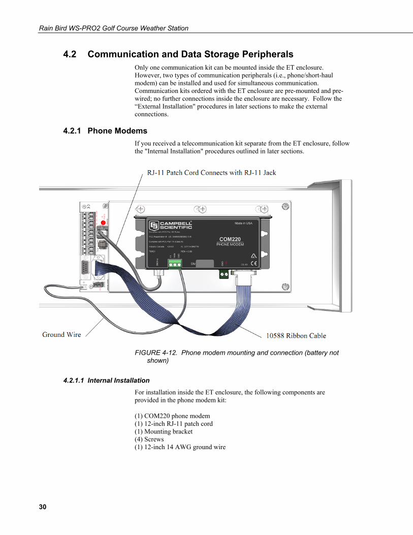
4. Replace the connector cover. The tab at the top of the connector cover slides into the opening on the back of the cross arm. Ensure that all cables and connector caps are under the cover before tightening the Phillips screw at the bottom of the cover. Make sure that all cables coming out of the top right of the connector cover are not being pinched. See FIGURE 4-11.
5. Tighten down the wire ties holding cabling to the wire tie harness and clip off any excess. See FIGURE 4-11.
FIGURE 4-11. Connector cover in place and lightning rod
29
Rain Bird WS-PRO2 Golf Course Weather Station
4.2 Communication and Data Storage Peripherals Only one communication kit can be mounted inside the ET enclosure. However, two types of communication peripherals (i.e., phone/short-haul modem) can be installed and used for simultaneous communication. Communication kits ordered with the ET enclosure are pre-mounted and pre-wired; no further connections inside the enclosure are necessary. Follow the “External Installation" procedures in later sections to make the external connections.
4.2.1 Phone Modems If you received a telecommunication kit separate from the ET enclosure, follow the "Internal Installation" procedures outlined in later sections.
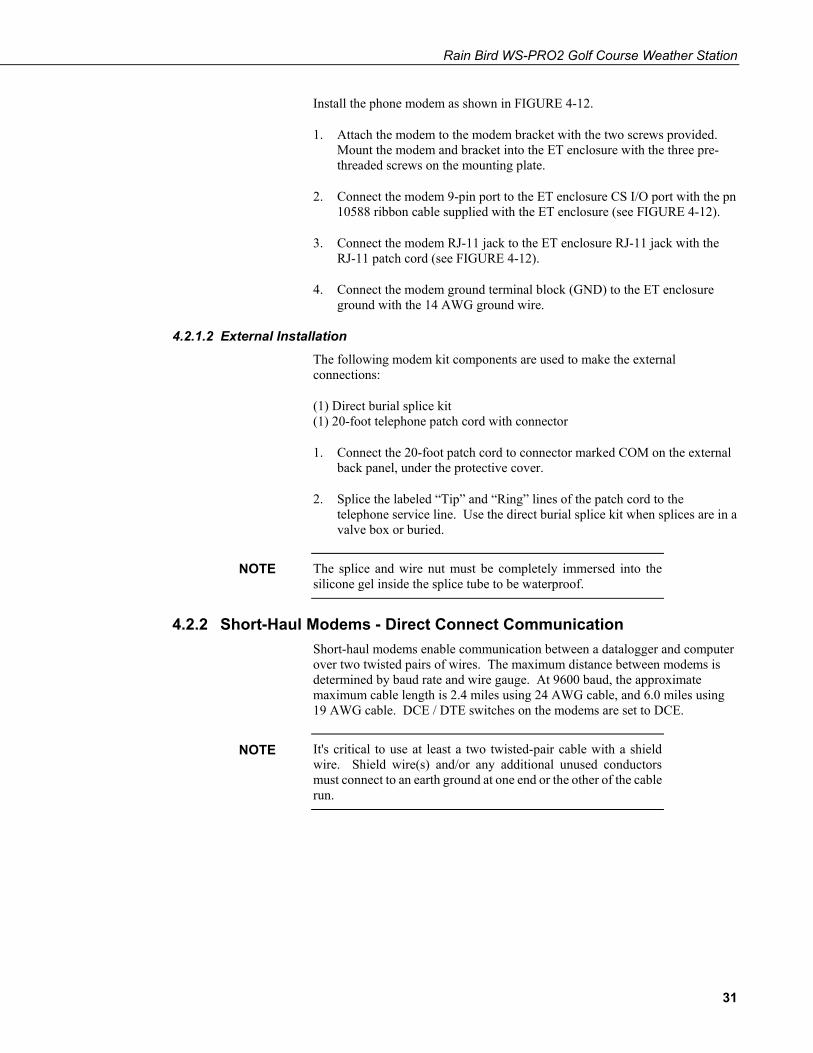
FIGURE 4-12. Phone modem mounting and connection (battery not shown)
4.2.1.1 Internal Installation For installation inside the ET enclosure, the following components are provided in the phone modem kit:
(1) COM220 phone modem (1) 12-inch RJ-11 patch cord (1) Mounting bracket (4) Screws (1) 12-inch 14 AWG ground wire
30
Rain Bird WS-PRO2 Golf Course Weather Station
Install the phone modem as shown in FIGURE 4-12.
1. Attach the modem to the modem bracket with the two screws provided. Mount the modem and bracket into the ET enclosure with the three pre-threaded screws on the mounting plate.
2. Connect the modem 9-pin port to the ET enclosure CS I/O port with the pn 10588 ribbon cable supplied with the ET enclosure (see FIGURE 4-12).
3. Connect the modem RJ-11 jack to the ET enclosure RJ-11 jack with the RJ-11 patch cord (see FIGURE 4-12).
4. Connect the modem ground terminal block (GND) to the ET enclosure ground with the 14 AWG ground wire.
4.2.1.2 External Installation The following modem kit components are used to make the external connections:
(1) Direct burial splice kit (1) 20-foot telephone patch cord with connector
1. Connect the 20-foot patch cord to connector marked COM on the external back panel, under the protective cover.
2. Splice the labeled “Tip” and “Ring” lines of the patch cord to the telephone service line. Use the direct burial splice kit when splices are in a valve box or buried.
The splice and wire nut must be completely immersed into the silicone gel inside the splice tube to be waterproof.
4.2.2 Short-Haul Modems - Direct Connect Communication Short-haul modems enable communication between a datalogger and computer over two twisted pairs of wires. The maximum distance between modems is determined by baud rate and wire gauge. At 9600 baud, the approximate maximum cable length is 2.4 miles using 24 AWG cable, and 6.0 miles using 19 AWG cable. DCE / DTE switches on the modems are set to DCE.
It's critical to use at least a two twisted-pair cable with a shield wire. Shield wire(s) and/or any additional unused conductors must connect to an earth ground at one end or the other of the cable run.
NOTE
NOTE
31
Rain Bird WS-PRO2 Golf Course Weather Station
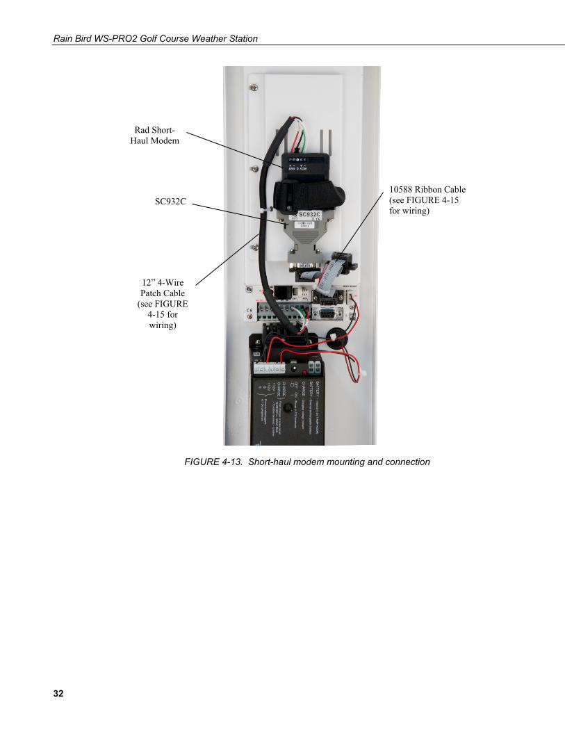
FIGURE 4-13. Short-haul modem mounting and connection
Rad Short- Haul Modem
SC932C
12” 4-Wire Patch Cable
(see FIGURE 4-15 for wiring)
10588 Ribbon Cable (see FIGURE 4-15 for wiring)
32
Rain Bird WS-PRO2 Golf Course Weather Station
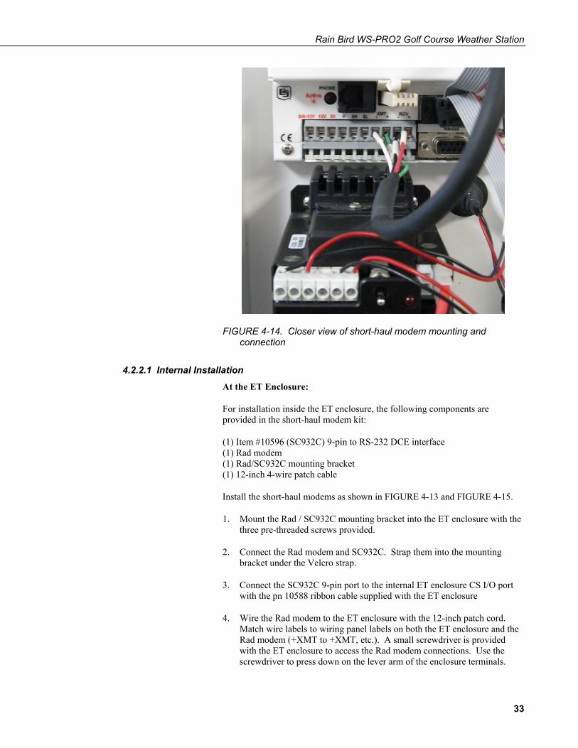
FIGURE 4-14. Closer view of short-haul modem mounting and connection
4.2.2.1 Internal Installation
At the ET Enclosure:
For installation inside the ET enclosure, the following components are provided in the short-haul modem kit:
(1) Item #10596 (SC932C) 9-pin to RS-232 DCE interface (1) Rad modem (1) Rad/SC932C mounting bracket (1) 12-inch 4-wire patch cable
Install the short-haul modems as shown in FIGURE 4-13 and FIGURE 4-15.
1. Mount the Rad / SC932C mounting bracket into the ET enclosure with the three pre-threaded screws provided.
2. Connect the Rad modem and SC932C. Strap them into the mounting bracket under the Velcro strap.
3. Connect the SC932C 9-pin port to the internal ET enclosure CS I/O port with the pn 10588 ribbon cable supplied with the ET enclosure
4. Wire the Rad modem to the ET enclosure with the 12-inch patch cord. Match wire labels to wiring panel labels on both the ET enclosure and the Rad modem (+XMT to +XMT, etc.). A small screwdriver is provided with the ET enclosure to access the Rad modem connections. Use the screwdriver to press down on the lever arm of the enclosure terminals.
33
Rain Bird WS-PRO2 Golf Course Weather Station
Pressing too hard on the lever arm can cause it to break!
At the PC:
For installation at the PC, the following components are provided in the short-haul modem kit:
(1) Rad modem (1) 5-foot 4-wire patch cable (1) Surge protector and case (1) 9-25 pin RS-232 serial cable (1) Length of user-supplied 14 AWG or larger wire
1. Mount the surge protector to a flat surface within 5 feet of the PC's serial port. Ground the center terminal to an earth (or building) ground using a user-supplied 14 AWG or larger wire.
2. Connect the 5-foot patch cord to the Rad modem making sure to match wire labels to terminal labels. Fasten the cable to the strain relief tab with a cable tie. Connect the Rad to the PC's serial port with the 9 to 25 pin serial cable.
3. Connect the user-supplied cable coming from the central PC valve box, and the 5-foot patch cord to the surge protector. See Section 4.2.2.2, External Installation, “At the PC” for MSP-1 wiring instructions at the PC location.
4.2.2.2 External Installation
At the ET Enclosure:
For the installation at the ET enclosure, the following components are provided in the short-haul modem kit:
(1) 20-foot 4-wire patch cable (2) Direct burial splice kits (1) Length of user-supplied Belden 9883 or equivalent cable
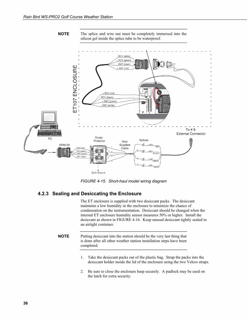
1. Coming from the central location, furnish and install a Belden #9883 or equivalent, direct burial type, communication cable over to the weather station location. The cable shall consist of three twisted pair of wires (20 gauge), each consisting of a bare copper drain wire, and an aluminum shield. The three twisted pair shall be color coded as follows: 1 pair “black” and “green”, 1 pair “black” and “red”, and 1 pair “black” and “white”. The “black” and “white” pair shall not be used, but kept as a spare pair.
2. The BLACK (-XMT) and GREEN (+XMT) pair of the Belden #9883 cable shall be connected to the BLACK and RED wires respectively, at the “FIELD” end of one of the MSP-1 surge arrestors. The WHITE (-XMT) and GREEN (+XMT) wires of the 20-foot communication cable furnished with the weather station shall be connected to the BLACK and RED wires respectively, at the “EQUIPMENT” end of the same MSP-1 surge arrestor.
WARNING
34
Rain Bird WS-PRO2 Golf Course Weather Station
3. The RED (+RCV) and BLACK (-RCV) pair shall be connected to the RED and BLACK wires respectively, at the “FIELD” end of the other MSP-1 surge arrestor. The RED (+RCV) and BLACK (-RCV) wires of the 20-foot communication cable furnished with the weather station shall be connected to the RED and BLACK wires respectively, at the “EQUIPMENT” end of the same MSP-1 surge arrestor.
4. The communication cable furnished with the weather station shall be routed through the 1 ½” diameter long sweep elbow to the base of the weather station, and up through the tower to the back of the datalogger enclosure. Connect the cable to the connector marked COM on the back of the ET enclosure.
All wire connections and splices in the communication wiring shall be made using 3-M DBY or equivalent direct burial connectors. DO NOT attempt to use any other type of connectors as communication signal may be impaired and poor communication may result.
At the PC:
There are no components included in the short-haul modem kit for installation of the communication wiring at the PC’s MSP-1 surge arrestor location. Use the existing central PC valve box and ground rod if present.
Valve access box components (not supplied) (1) Existing 18” x 24” valve box (2) MSP-1 surge arrestors (1) MGP-1 grounding plate (1) 5/8” copper ground rod (4) Direct burial splice kits
1. Coming from the surge arrestor mounted near the PC, furnish and install a Belden #9883 or equivalent, direct burial type, communication cable over to the access box at the central valve box location. Specifications of this cable are listed earlier in Section 4.2.2.2, External Installation. The BLACK (-XMT) and GREEN (+XMT) pair of the Belden #9883 cable shall be connected to the BLACK and RED wires respectively, at the “FIELD” end of one of the MSP-1 surge arrestors. The BLACK (-XMT) and GREEN (+XMT) wires of the Belden #9883 communication cable going to the weather station shall be connected to the BLACK and RED wires respectively, at the “EQUIPMENT” end of the same MSP-1 surge arrestor.
2. The RED (+RCV) and BLACK (-RCV) pair of the Belden #9883 cable shall be connected to the RED and BLACK wires respectively, at the “FIELD” end of the other MSP-1 surge arrestor. The RED (+RCV) and BLACK (-RCV) wires of the Belden #9883 communication cable going to the weather station shall be connected to the RED and BLACK wires respectively, at the “EQUIPMENT” end of the same MSP-1 surge arrestor.
3. The user-supplied communication cable shall be routed from the valve access box and into the building per national and/or local electrical codes.
NOTE
35
Rain Bird WS-PRO2 Golf Course Weather Station
The splice and wire nut must be completely immersed into the silicon gel inside the splice tube to be waterproof.
FIGURE 4-15. Short-haul model wiring diagram
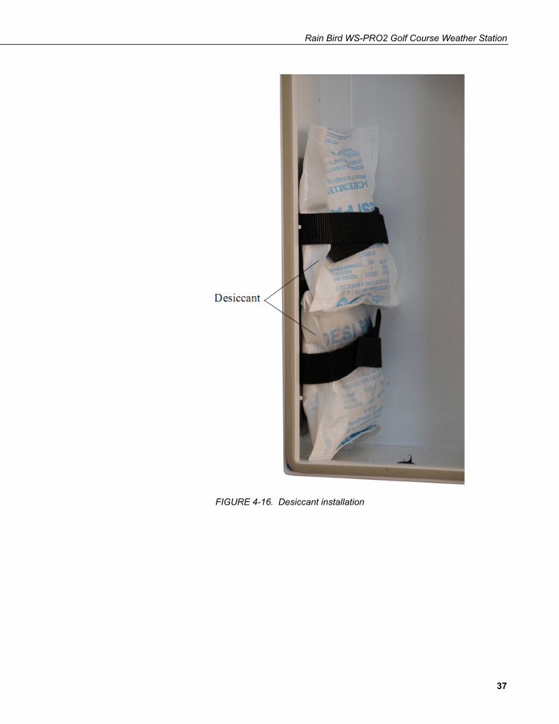
4.2.3 Sealing and Desiccating the Enclosure The ET enclosure is supplied with two desiccant packs. The desiccant maintains a low humidity in the enclosure to minimize the chance of condensation on the instrumentation. Desiccant should be changed when the internal ET enclosure humidity sensor measures 50% or higher. Install the desiccant as shown in FIGURE 4-16. Keep unused desiccant tightly sealed in an airtight container.
Putting desiccant into the station should be the very last thing that is done after all other weather station installation steps have been completed.
1. Take the desiccant packs out of the plastic bag. Strap the packs into the desiccant holder inside the lid of the enclosure using the two Velcro straps.
2. Be sure to close the enclosure hasp securely. A padlock may be used on the latch for extra security.
NOTE
NOTE
36
Rain Bird WS-PRO2 Golf Course Weather Station
FIGURE 4-16. Desiccant installation
37
Rain Bird WS-PRO2 Golf Course Weather Station
5. Installation of Sensor Arm 5.1 Components
(1) WS-PRO2 crossarm with sensors (1) Met One 034B Wind Sensor (1) White mounting shaft for 034B (1) Gill radiation shield
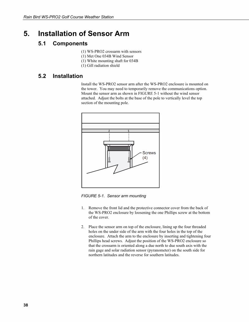
5.2 Installation Install the WS-PRO2 sensor arm after the WS-PRO2 enclosure is mounted on the tower. You may need to temporarily remove the communications option. Mount the sensor arm as shown in FIGURE 5-1 without the wind sensor attached. Adjust the bolts at the base of the pole to vertically level the top section of the mounting pole.
FIGURE 5-1. Sensor arm mounting
1. Remove the front lid and the protective connector cover from the back of the WS-PRO2 enclosure by loosening the one Phillips screw at the bottom of the cover.
2. Place the sensor arm on top of the enclosure, lining up the four threaded holes on the under side of the arm with the four holes in the top of the enclosure. Attach the arm to the enclosure by inserting and tightening four Phillips head screws. Adjust the position of the WS-PRO2 enclosure so that the crossarm is oriented along a due north to due south axis with the rain gage and solar radiation sensor (pyranometer) on the south side for northern latitudes and the reverse for southern latitudes.
38
Rain Bird WS-PRO2 Golf Course Weather Station
5.3 Sensor Connection Refer to 4, Instrumentation Installation, for sensor connection details.
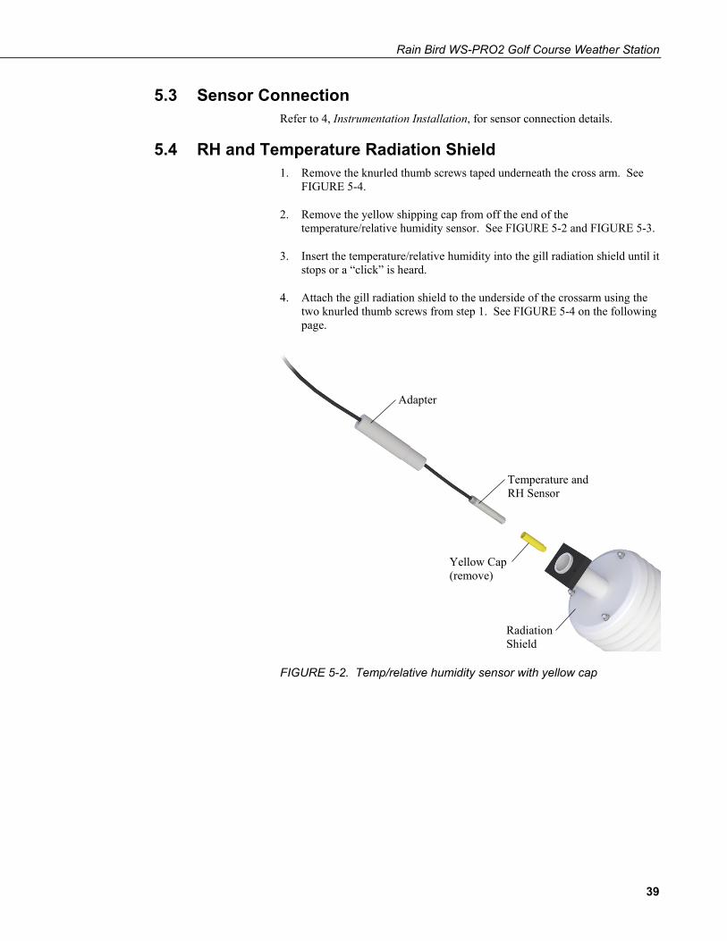
5.4 RH and Temperature Radiation Shield 1. Remove the knurled thumb screws taped underneath the cross arm. See
FIGURE 5-4.
2. Remove the yellow shipping cap from off the end of the temperature/relative humidity sensor. See FIGURE 5-2 and FIGURE 5-3.
3. Insert the temperature/relative humidity into the gill radiation shield until it stops or a “click” is heard.
4. Attach the gill radiation shield to the underside of the crossarm using the two knurled thumb screws from step 1. See FIGURE 5-4 on the following page.
FIGURE 5-2. Temp/relative humidity sensor with yellow cap
Adapter
Temperature and RH Sensor
Yellow Cap (remove)
Radiation Shield
39
Rain Bird WS-PRO2 Golf Course Weather Station
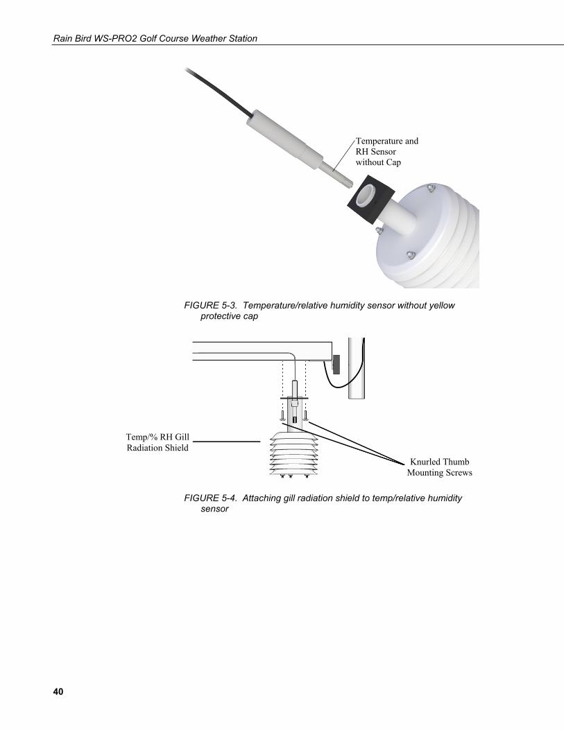
FIGURE 5-3. Temperature/relative humidity sensor without yellow protective cap
FIGURE 5-4. Attaching gill radiation shield to temp/relative humidity sensor
Knurled Thumb Mounting Screws
Temp/% RH Gill Radiation Shield
Temperature and RH Sensor without Cap
40
Rain Bird WS-PRO2 Golf Course Weather Station
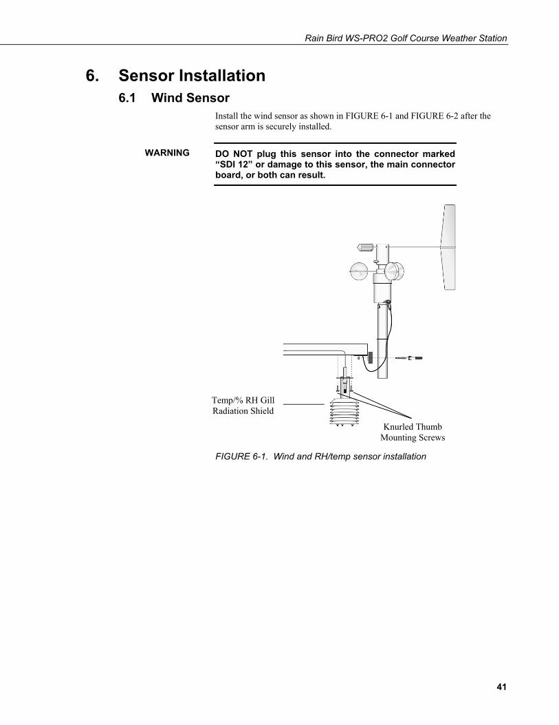
6. Sensor Installation 6.1 Wind Sensor
Install the wind sensor as shown in FIGURE 6-1 and FIGURE 6-2 after the sensor arm is securely installed.
DO NOT plug this sensor into the connector marked “SDI 12” or damage to this sensor, the main connector board, or both can result.
FIGURE 6-1. Wind and RH/temp sensor installation
WARNING
Knurled Thumb Mounting Screws
Temp/% RH Gill Radiation Shield
41
Rain Bird WS-PRO2 Golf Course Weather Station
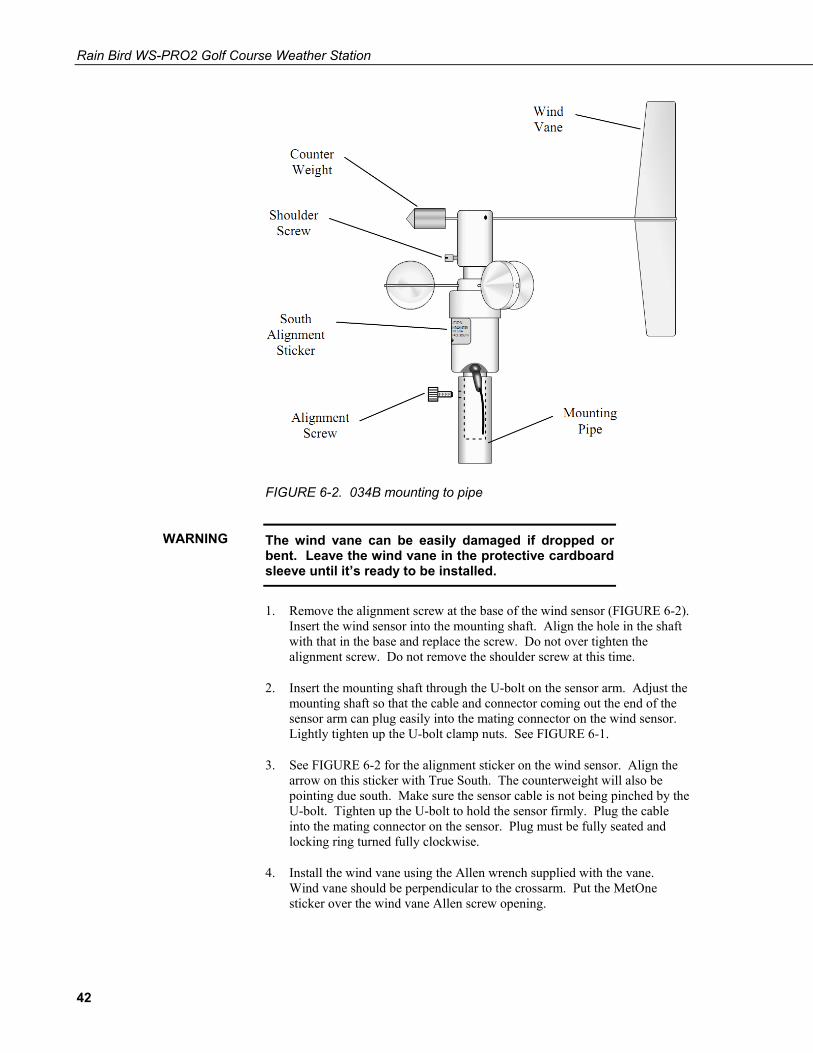
FIGURE 6-2. 034B mounting to pipe
The wind vane can be easily damaged if dropped or bent. Leave the wind vane in the protective cardboard sleeve until it’s ready to be installed.
1. Remove the alignment screw at the base of the wind sensor (FIGURE 6-2). Insert the wind sensor into the mounting shaft. Align the hole in the shaft with that in the base and replace the screw. Do not over tighten the alignment screw. Do not remove the shoulder screw at this time.
2. Insert the mounting shaft through the U-bolt on the sensor arm. Adjust the mounting shaft so that the cable and connector coming out the end of the sensor arm can plug easily into the mating connector on the wind sensor. Lightly tighten up the U-bolt clamp nuts. See FIGURE 6-1.
3. See FIGURE 6-2 for the alignment sticker on the wind sensor. Align the arrow on this sticker with True South. The counterweight will also be pointing due south. Make sure the sensor cable is not being pinched by the U-bolt. Tighten up the U-bolt to hold the sensor firmly. Plug the cable into the mating connector on the sensor. Plug must be fully seated and locking ring turned fully clockwise.
4. Install the wind vane using the Allen wrench supplied with the vane. Wind vane should be perpendicular to the crossarm. Put the MetOne sticker over the wind vane Allen screw opening.
WARNING
42
Rain Bird WS-PRO2 Golf Course Weather Station
5. Remove and keep the shoulder screw. The shoulder screw will be needed for replacing bearings and/or potentiometer in the future. The wind vane and cups should turn freely.
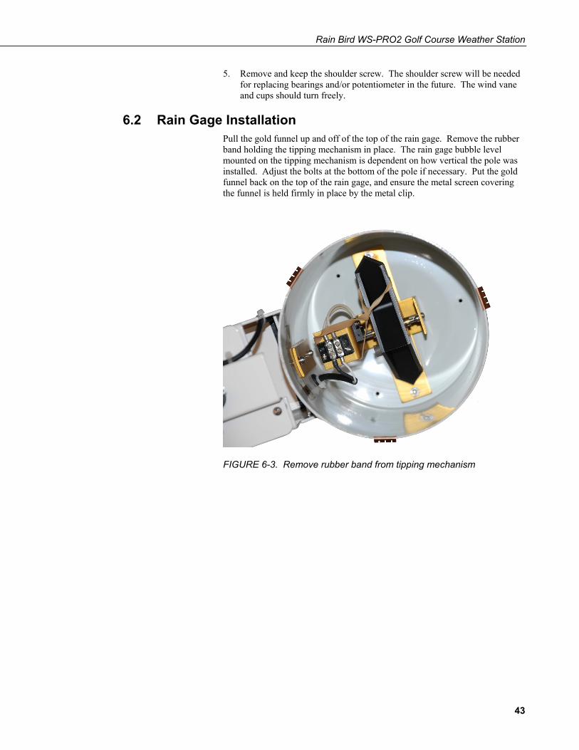
6.2 Rain Gage Installation Pull the gold funnel up and off of the top of the rain gage. Remove the rubber band holding the tipping mechanism in place. The rain gage bubble level mounted on the tipping mechanism is dependent on how vertical the pole was installed. Adjust the bolts at the bottom of the pole if necessary. Put the gold funnel back on the top of the rain gage, and ensure the metal screen covering the funnel is held firmly in place by the metal clip.
FIGURE 6-3. Remove rubber band from tipping mechanism
43
Rain Bird WS-PRO2 Golf Course Weather Station
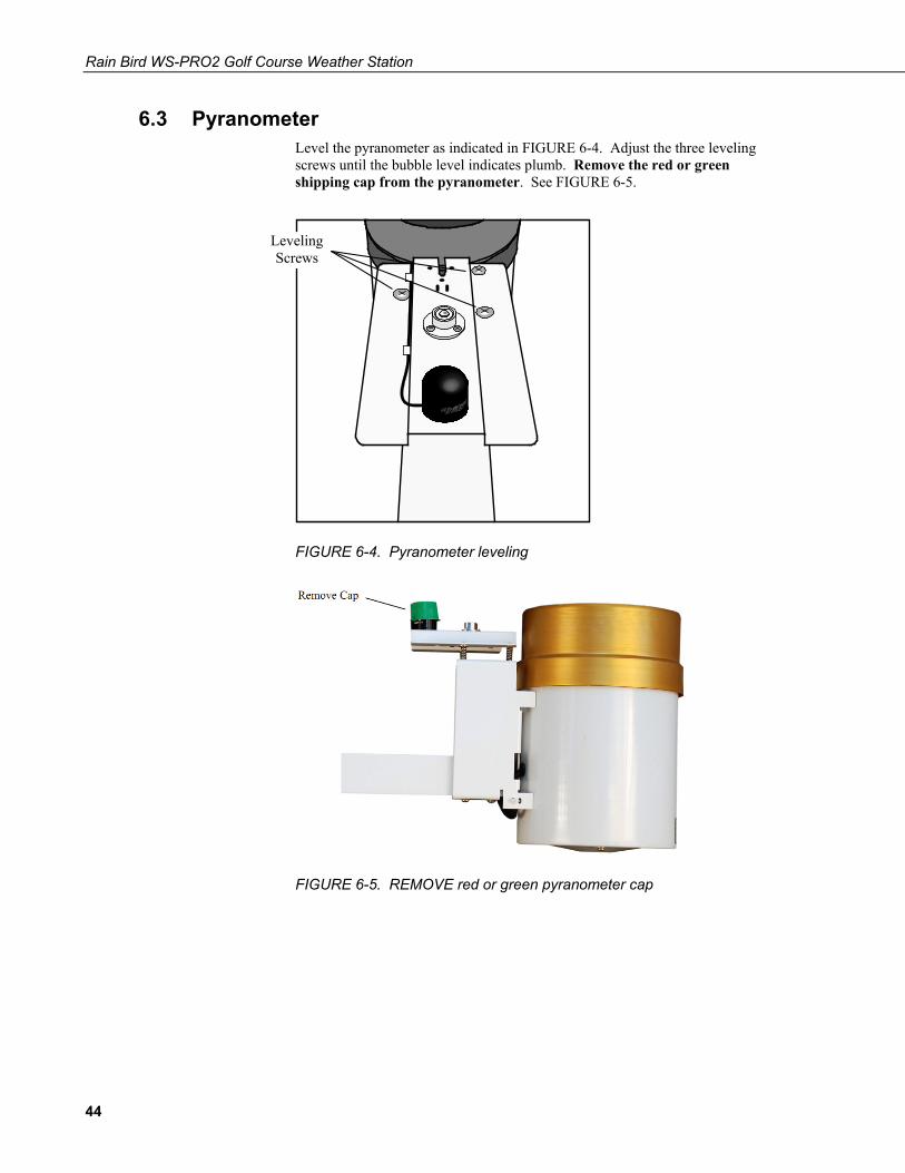
6.3 Pyranometer Level the pyranometer as indicated in FIGURE 6-4. Adjust the three leveling screws until the bubble level indicates plumb. Remove the red or green shipping cap from the pyranometer. See FIGURE 6-5.
FIGURE 6-4. Pyranometer leveling
FIGURE 6-5. REMOVE red or green pyranometer cap
Leveling Screws
44
Rain Bird WS-PRO2 Golf Course Weather Station
6.4 Soil Temperature Sensor (Optional - See Section 2.3.5) Soil temperature sensors do NOT have an armored outer jacket. The jacket is waterproof but NOT cut proof. The recommended method is to bury conduit from the weather station to the soil temperature site and route the sensor cable through the conduit. Bury the end of the sensor so it is in contact with the soil surface to be measured. See manual for complete instructions.
This sensor could be plugged into one of three possible connectors on the back of the WS-PRO2 station. Check the programming software for correct station connection.
The cable used with the soil temperature sensor is waterproof but not armored. Route cable through conduit if rocky soils or rodents are present.
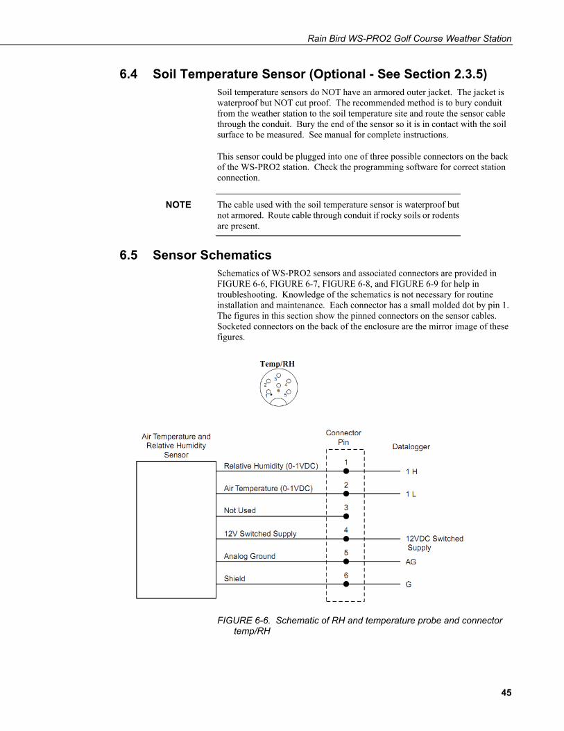
6.5 Sensor Schematics Schematics of WS-PRO2 sensors and associated connectors are provided in FIGURE 6-6, FIGURE 6-7, FIGURE 6-8, and FIGURE 6-9 for help in troubleshooting. Knowledge of the schematics is not necessary for routine installation and maintenance. Each connector has a small molded dot by pin 1. The figures in this section show the pinned connectors on the sensor cables. Socketed connectors on the back of the enclosure are the mirror image of these figures.
FIGURE 6-6. Schematic of RH and temperature probe and connector temp/RH
NOTE
45
Rain Bird WS-PRO2 Golf Course Weather Station
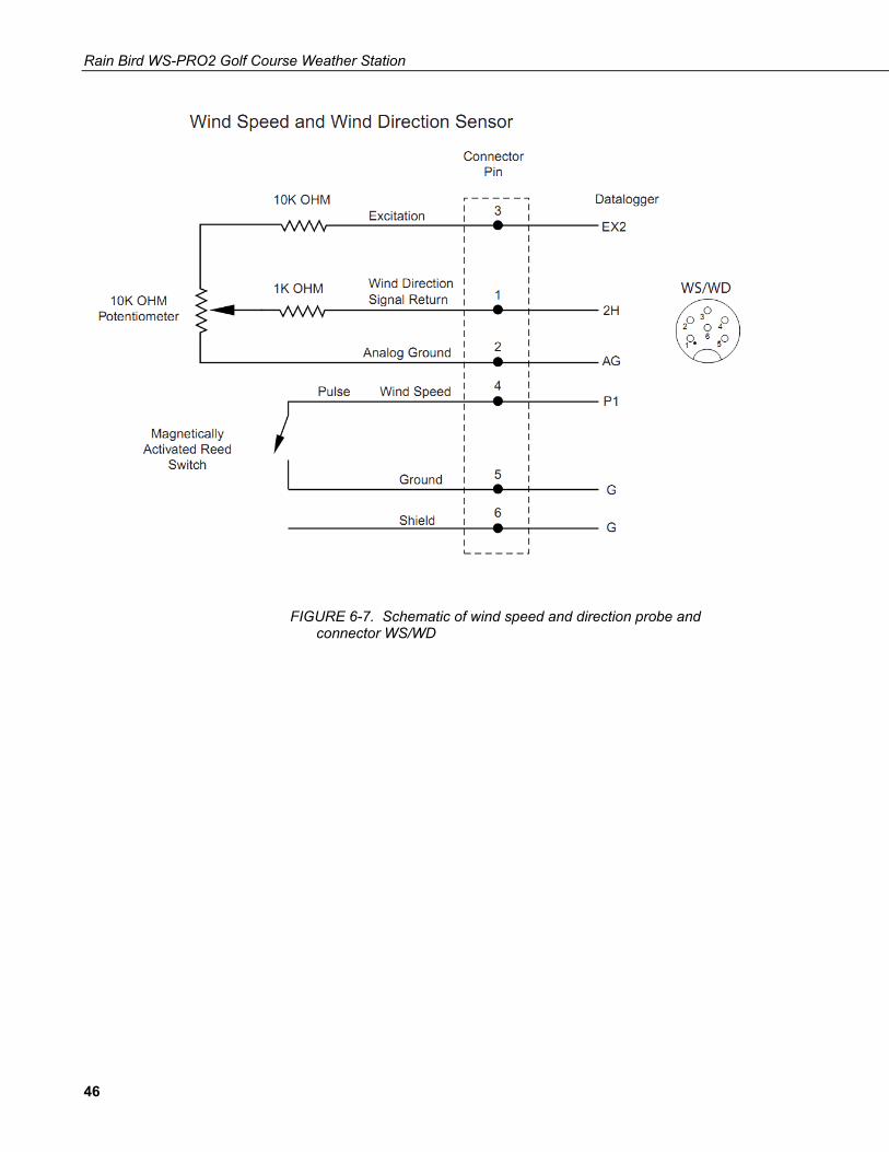
FIGURE 6-7. Schematic of wind speed and direction probe and connector WS/WD
46

Rain Bird WS-PRO2 Golf Course Weather Station
FIGURE 6-8. Schematic of solar radiation sensor and connector solar radiation
47
Rain Bird WS-PRO2 Golf Course Weather Station
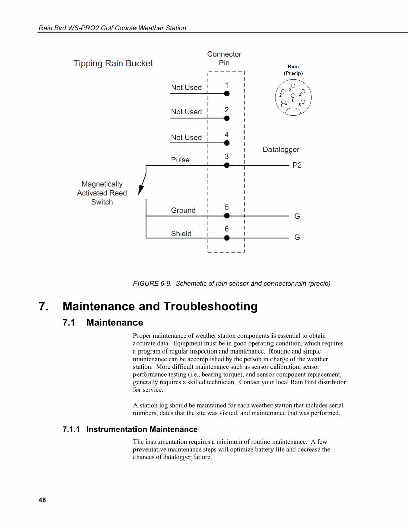
FIGURE 6-9. Schematic of rain sensor and connector rain (precip)
7. Maintenance and Troubleshooting 7.1 Maintenance
Proper maintenance of weather station components is essential to obtain accurate data. Equipment must be in good operating condition, which requires a program of regular inspection and maintenance. Routine and simple maintenance can be accomplished by the person in charge of the weather station. More difficult maintenance such as sensor calibration, sensor performance testing (i.e., bearing torque), and sensor component replacement, generally requires a skilled technician. Contact your local Rain Bird distributor for service.
A station log should be maintained for each weather station that includes serial numbers, dates that the site was visited, and maintenance that was performed.
7.1.1 Instrumentation Maintenance The instrumentation requires a minimum of routine maintenance. A few preventative maintenance steps will optimize battery life and decrease the chances of datalogger failure.
48
Rain Bird WS-PRO2 Golf Course Weather Station
7.1.2 Batteries Rechargeable power supplies should be connected to an AC transformer or unregulated solar panel at all times. The charge indicating diode should be "ON" when voltage to the charging circuitry is present. Be aware of battery voltage that consistently decreases over time, which indicates a failure in the charging circuitry. Smart Weather automatically programs the weather station to measure battery voltage.
7.1.3 Desiccant Enclosure humidity is monitored in the WS-PRO2 enclosure system by a RH sensor incorporate inside the enclosure. Change the desiccant packs when the enclosure RH exceeds 50%. The enclosure RH sensor should be changed every 5+ years.
7.1.4 Sensor Maintenance Sensor maintenance should be performed at regular intervals, depending on the desired accuracy and the conditions of use. A suggested maintenance schedule is outlined below. Log file is for one year of station use.
1 week
• Check the rain gage screen and funnel for debris and level.
1 month
• Check the solar radiation sensor (pyranometer) for level and contamination. Gently clean with blast of dry hair, soft camel hair brush, or clean water if needed.
• Do a visual/audio inspection of the anemometer at low wind speeds. Worn bearings can cause the wind cups to spin in an uneven manner and/or make a grinding sound.
3 months
• Clean the gill radiation shield by removing the two Phillips screws holding it to the sensor arm. Gently pull the sensor out of the shield. Clean the gill shield using warm mildly soapy water. Rinse with clean water and allow the shield to dry before putting it back on the sensor arm.
• If necessary clean the white filter element on the end of the temp/RH sensor. To clean the filter, unscrew it from off the end of the sensor and put it in a cup of CLEAN DISTILLED WATER. Use no soap. Agitate the filter in the cup of water. Remove the filter and allow to air dry before putting it back on the end of the sensor.
1 year
• Replace wind speed (anemometer) bearings. Contact your local Rain Bird distributor for service.
• Replace wind speed (anemometer) reed switch if needed. Contact your local Rain Bird distributor for service.
49

Rain Bird WS-PRO2 Golf Course Weather Station
• Check calibration of the temp/RH probe. Sensor will tend to drift up over time giving readings higher then 100%. Replace RH chip (item# 9598) if necessary.
• Replace desiccant in enclosure housing as needed.
2 years
• Send the solar radiation sensor (pyranometer) in for calibration. Contact your local Rain Bird distributor for service. Sensor cannot be calibrated in the field. (Some users recommend calibrating this sensor on a yearly basis.)
• Note: Sensor could be away for as long as a month and a half to be calibrated. Best to send sensor in during an off part of the growing season or when solar radiation is not vital.
• Replace wind direction potentiometer if needed. Contact your local Rain Bird distributor for service.
• Replace enclosure gasket if necessary. Contact your local Rain Bird distributor for service.
4-5 years
• Check all cabling for sensors, communication, and power. Replace as required.
• Check enclosure relative humidity sensor (item# 10070). To check this sensor, take the lid off the enclosure during routine desiccant replacement and leave it off for 5 – 10 minutes before putting in new desiccant. While the lid is off the enclosure, compare the internal enclosure humidity to the air humidity. Replace if > 10% off.
General Maintenance
• An occasional cleaning of the glass on the solar panel will improve its efficiency. Use warm mildly soapy water and a clean cloth. Rinse with clean water.
• Check sensor leads and cable for cracking, deterioration, proper routing, and strain relief.
• Check the tower for structural damage, proper alignment, and for level/plumb.
7.2 Troubleshooting 7.2.1 No Response Using the CR1000KD Keypad
Check keypad response after each of the following steps.
• Make sure the battery has been installed and the power switch set to “ON” (see Section 4.1.1, Battery Installation, through Section 4.1.3, AC Power Installation).
50
Rain Bird WS-PRO2 Golf Course Weather Station
• Use a voltmeter to measure the voltage on the 12 V and G terminals (see FIGURE 4-3); the voltage must be between 9.6 and 16 VDC.
• Use a voltmeter to measure the voltage on the 5V and G terminals (see FIGURE 4-3); the voltage must be between 4.9 and 5.1 VDC.
• Disconnect the temp/RH sensor from the back of the enclosure.
• Disconnect the 9-pin ribbon cable from any communication option used with the station so that only the keypad is attached to the 9-pin plug in the lower right hand corner of the enclosure.
• Cycle the power to the datalogger by switching the power supply to “OFF”, then to “ON” or disconnecting and reconnecting the battery plug. Keypad should power up.
• Contact your local Rain Bird distributor if there is still no response.
7.2.2 No Response from Datalogger through SC32B, Rad Modem, or Phone Modem
At the datalogger:
• Make sure the battery has been installed and the power switch set to “ON” (see Section 4.1.1, Battery Installation, through Section 4.1.3, AC Power Installation).
• Use a voltmeter to measure the voltage on the 12V and G terminals (see FIGURE 4-3); the voltage must be between 9.6 and 16 VDC.
• Use a voltmeter to measure the voltage on the 5V and G terminals (see FIGURE 4-3); the voltage must be between 4.9 and 5.1 VDC.
• Make sure the datalogger is connected to the communication peripheral, and the communication peripheral properly installed and configured (Section 3.5, Weather Station AC Power Wiring).
At the computer:
• Make sure calling software is properly configured (PC200W, VisualWeather, or LoggerNet).
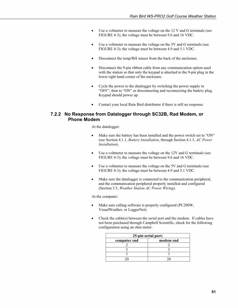
• Check the cable(s) between the serial port and the modem. If cables have not been purchased through Campbell Scientific, check for the following configuration using an ohm meter:
25-pin serial port: computer end modem end
2 2 3 3 7 7
20 20
51
Rain Bird WS-PRO2 Golf Course Weather Station
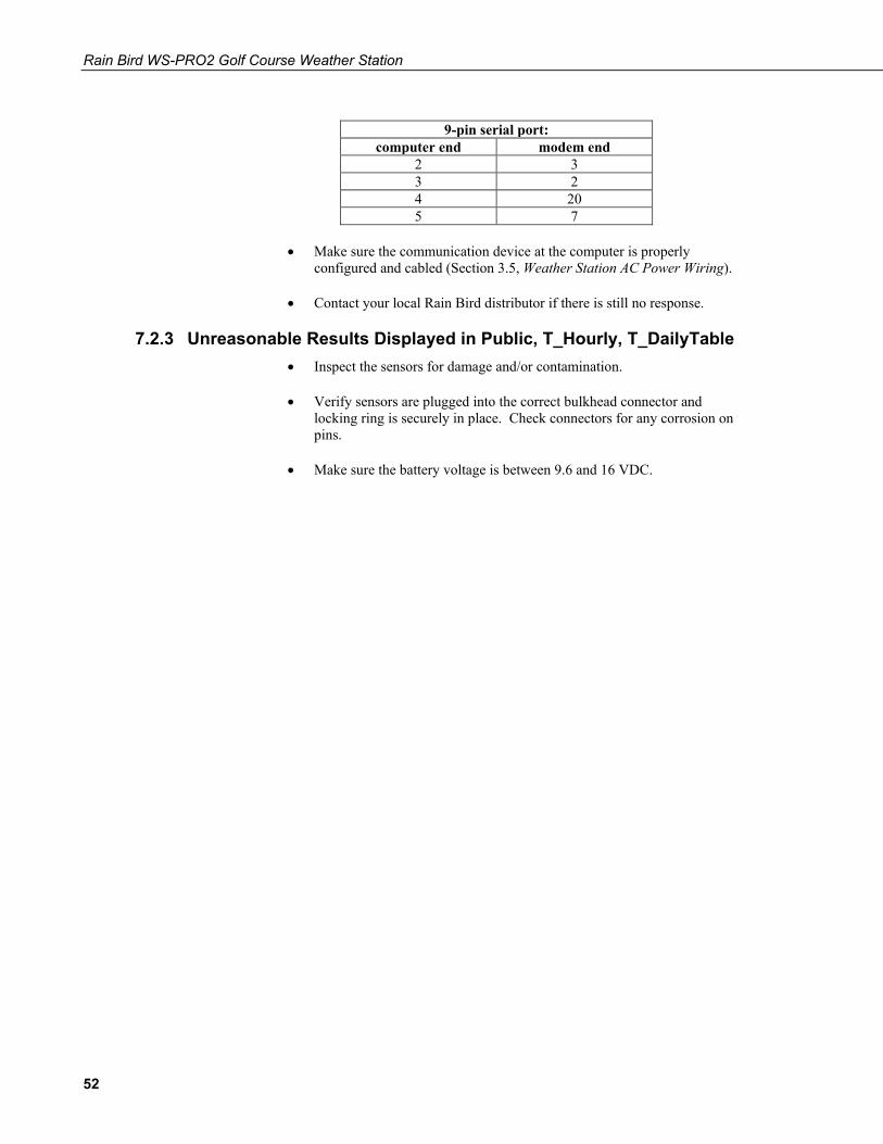
9-pin serial port:
computer end modem end 2 3 3 2 4 20 5 7
• Make sure the communication device at the computer is properly
configured and cabled (Section 3.5, Weather Station AC Power Wiring).
• Contact your local Rain Bird distributor if there is still no response.
7.2.3 Unreasonable Results Displayed in Public, T_Hourly, T_DailyTable • Inspect the sensors for damage and/or contamination.
• Verify sensors are plugged into the correct bulkhead connector and locking ring is securely in place. Check connectors for any corrosion on pins.
• Make sure the battery voltage is between 9.6 and 16 VDC.
52
Appendix A. Grounding Recommendations A.1 Grounding System Installation
To prevent lightning damage to your equipment, Rain Bird recommends installing a grounding system for the equipment (including controllers, weather stations, and central control systems). The grounding system discharges lightning-induced electrical current into the earth rather than allow the surge to pass through power wires or field wires to your equipment’s electronic components.
A.1.1 Ground Resistance Ground resistance occurs when grounding system components, or the soil itself, oppose the flow of electricity into the earth. Ground resistance is measured in units called “ohms” (Ω). The higher the ground resistance (higher ohm readings), the less chance the surge will be shunted to ground rather than to the equipment’s electronic components.
FIGURE A-1 shows points where grounding systems can develop resistance. To decrease ground resistance, Rain Bird recommends irrigating the soil around the grounding system. Each grounding system should have a dedicated irrigation zone with sprinkler heads and its own watering program to maintain soil moisture around the grounding system.
A properly installed grounding system should maintain a maximum ground resistance of 10 ohms or less. If you are unable to reach a resistance of 10 ohms or less, you can decrease resistance by surrounding the grounding rods or plates with ground enhancement material, such as POWER SET from Paige Electric Corporation (pn 1820058), or GEM from ERICO (pn GEM-25A).
If ground resistance still measures higher than 10 ohms, you can extend the ground rod length as described in “Ground Rod Stacking,” or use additional grounding rods, as shown in grounding system design “Y” (Alternate).
A.1.2 Installation Requirement The following requirements apply to all grounding system designs (design Y and the “Grounding Plate” design). All grounding rods or plates must be connected together below grade with #6 AWG or larger solid bare copper wire.
Install the connecting wire in as straight a line as possible. If you must make a turn or bend in the wire, make the turn in a sweeping curve with a minimum radius of eight inches and a minimum included angle of 90°.
To minimize resistance, the copper wire must be pre-welded to the grounding rods/plates, or welded to the rods/plates using an exothermic welding process at the site.
Make sure all welds are secure before burying the grounding rods. Rods and plates with welded joints do not need periodic visual inspection and can be
A-1

Appendix A. Grounding Recommendations
fully buried (no valve box required). Measure the ground resistance around the grounding system after installation, and once every year after that.
The ground wire from the equipment to the grounding system should be as short as possible and have no bends, kinks, or coils in the wire.
Inspect the grounding system’s clamped connections to the equipment (not the welded grounding system connections) once a year to make sure they are secure and corrosion-free.
FIGURE A-1. Grounding systems can develop resistance at many points
A.1.3 Ground Rod Stacking Threaded couplers (shown in FIGURE A-2) are ground rod splices. If a single grounding rod fails to produce 10-ohm ground resistance (maximum), threaded couplers can be used to “stack” grounding rods.
Use threaded couplers made of the same material as your grounding rods.
Stacking ground rods increases the total effective rod length, decreasing ground resistance. Joining the rods together with threaded couplers forms a secure connection so the grounding rods can be assembled quickly and easily.
NOTE
NOTE
A-2
Appendix A. Grounding Recommendations
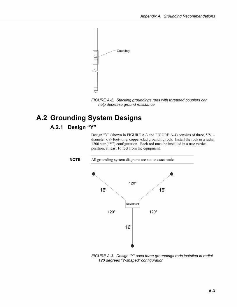
FIGURE A-2. Stacking groundings rods with threaded couplers can help decrease ground resistance
A.2 Grounding System Designs A.2.1 Design “Y”
Design “Y” (shown in FIGURE A-3 and FIGURE A-4) consists of three, 5/8” -diameter x 8- foot-long, copper-clad grounding rods. Install the rods in a radial 1200 star (“Y”) configuration. Each rod must be installed in a true vertical position, at least 16 feet from the equipment.
All grounding system diagrams are not to exact scale.
FIGURE A-3. Design “Y” uses three groundings rods installed in radial 120 degrees “Y-shaped” configuration
NOTE
A-3
Appendix A. Grounding Recommendations
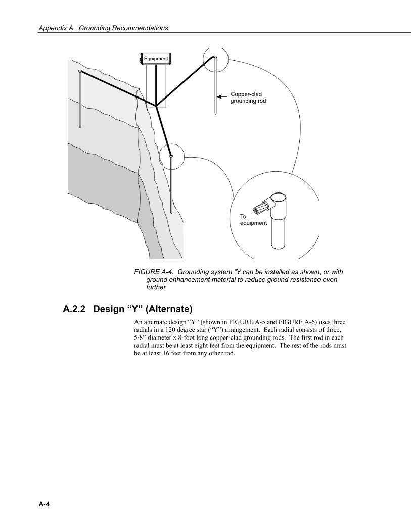
FIGURE A-4. Grounding system “Y can be installed as shown, or with ground enhancement material to reduce ground resistance even further
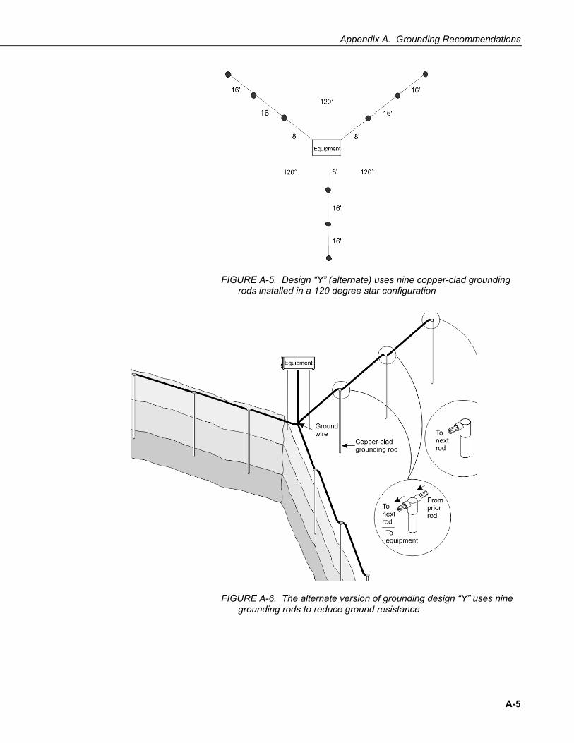
A.2.2 Design “Y” (Alternate) An alternate design “Y” (shown in FIGURE A-5 and FIGURE A-6) uses three radials in a 120 degree star (“Y”) arrangement. Each radial consists of three, 5/8”-diameter x 8-foot long copper-clad grounding rods. The first rod in each radial must be at least eight feet from the equipment. The rest of the rods must be at least 16 feet from any other rod.
A-4
Appendix A. Grounding Recommendations
FIGURE A-5. Design “Y” (alternate) uses nine copper-clad grounding rods installed in a 120 degree star configuration
FIGURE A-6. The alternate version of grounding design “Y” uses nine grounding rods to reduce ground resistance
A-5
Appendix A. Grounding Recommendations
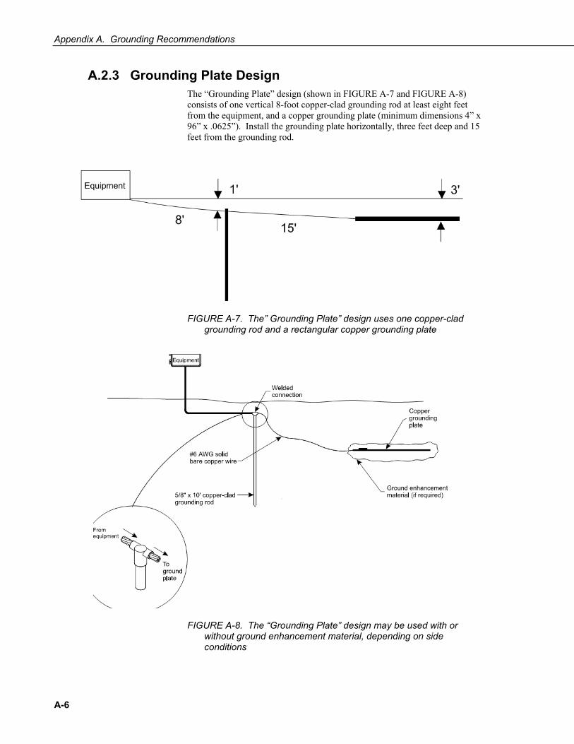
A.2.3 Grounding Plate Design The “Grounding Plate” design (shown in FIGURE A-7 and FIGURE A-8) consists of one vertical 8-foot copper-clad grounding rod at least eight feet from the equipment, and a copper grounding plate (minimum dimensions 4” x 96” x .0625”). Install the grounding plate horizontally, three feet deep and 15 feet from the grounding rod.
FIGURE A-7. The” Grounding Plate” design uses one copper-clad grounding rod and a rectangular copper grounding plate
FIGURE A-8. The “Grounding Plate” design may be used with or without ground enhancement material, depending on side conditions
A-6
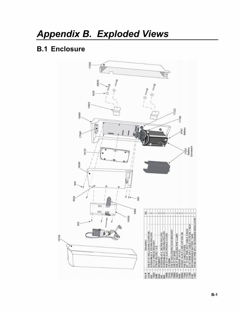
Appendix B. Exploded Views B.1 Enclosure
B-1
Appendix B. Exploded Views
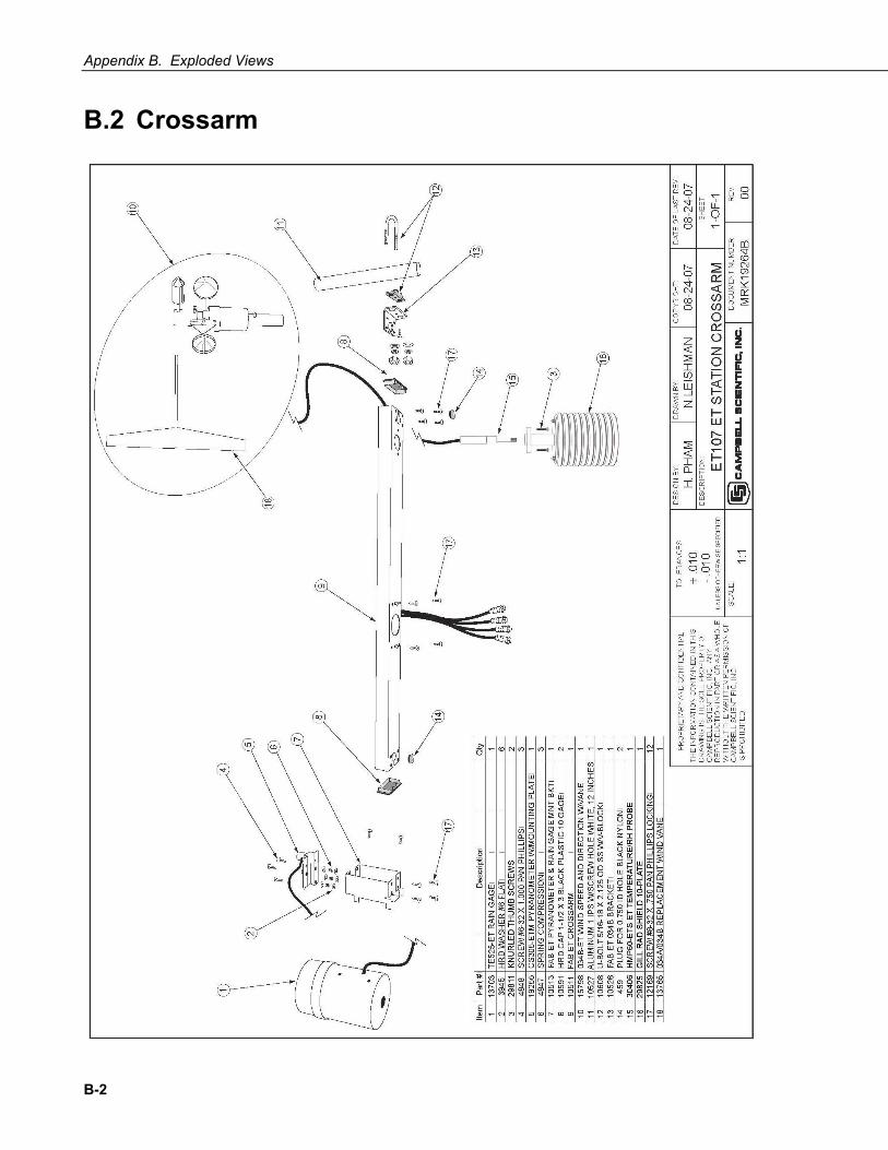
B.2 Crossarm
B-2

Appendix C. Maintenance Records Station Installation Date: __________________
CLEAN/INSPECT RAIN GAGE SENSOR (Recommended - Weekly)
CLEAN/INSPECT RAIN GAGE SENSOR (Recommended - Weekly)
Date OK/Comments Date OK/Comments
C-1
Appendix C. Maintenance Records
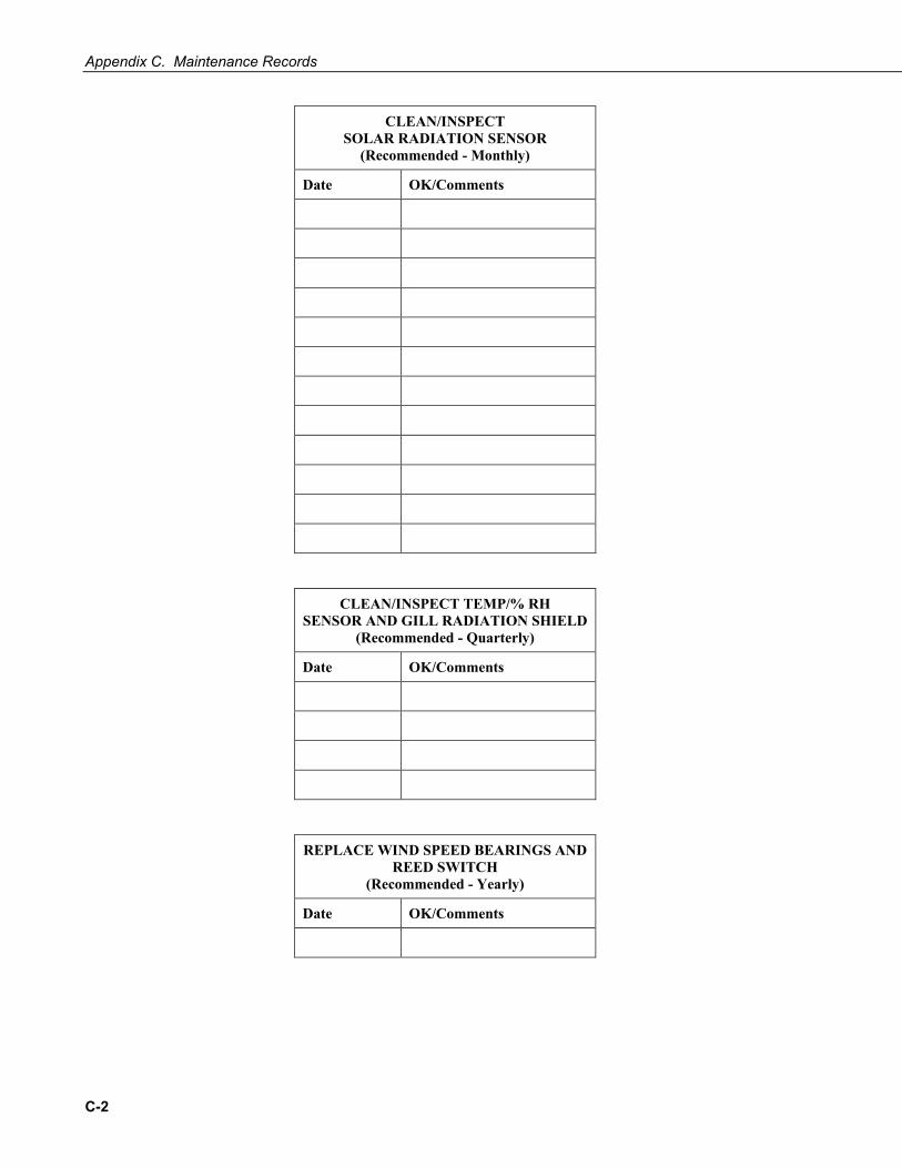
CLEAN/INSPECT SOLAR RADIATION SENSOR
(Recommended - Monthly)
Date OK/Comments
CLEAN/INSPECT TEMP/% RH SENSOR AND GILL RADIATION SHIELD
(Recommended - Quarterly)
Date OK/Comments
REPLACE WIND SPEED BEARINGS AND REED SWITCH
(Recommended - Yearly)
Date OK/Comments
C-2
Appendix C. Maintenance Records
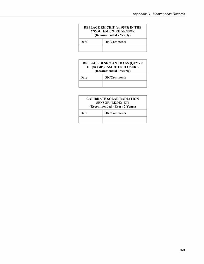
REPLACE RH CHIP (pn 9598) IN THE CS500 TEMP/% RH SENSOR
(Recommended - Yearly)
Date OK/Comments
REPLACE DESICCANT BAGS (QTY - 2 OF pn 4905) INSIDE ENCLOSURE
(Recommended - Yearly)
Date OK/Comments
CALIBRATE SOLAR RADIATION SENSOR (LI200X-ET)
(Recommended - Every 2 Years)
Date OK/Comments
C-3

Appendix C. Maintenance Records
C-4