
Wärtsilä 46 Technology Review - · PDF fileWÄRTSILÄ 46 TECHNOLOGY REVIEW...
20
WÄRTSILÄ 46 TECHNOLOGY REVIEW
Transcript of Wärtsilä 46 Technology Review - · PDF fileWÄRTSILÄ 46 TECHNOLOGY REVIEW...

WÄRTSILÄ 46 TECHNOLOGY REVIEW

2

This is a summary of Wärtsilä’s approach to design and
technology in the Wärtsilä 46 engine.
WÄRTSILÄ 46 TECHNOLOGY REVIEW
DESIGN PHILOSOPHY................................................... 4
DEVELOPMENT POLICY................................................ 4
EXHAUST EMISSIONS................................................... 5
WÄRTSILÄ WETPAC HUMIDIFICATION............................ 6
DIRECT WATER INJECTION (DWI) .................................. 6
FUEL SYSTEM.............................................................. 7
FUELS ......................................................................... 7
TURBOCHARGING SYSTEM........................................... 8
PISTON ...................................................................... 9
PISTON RING SET ........................................................ 9
CYLINDER LINER AND ANTI-POLISHING RING................. 9
CONNECTING ROD..................................................... 11
CRANKSHAFT ............................................................ 11
CYLINDER HEAD ........................................................ 11
CAMSHAFT AND VALVE GEAR..................................... 12
BEARINGS ................................................................. 12
ENGINE BLOCK .......................................................... 13
RESILIENT MOUNTING................................................ 14
COOLING SYSTEMS ................................................... 15
LUBRICATING OIL SYSTEM ......................................... 15
AUTOMATION SYSTEM............................................... 16
MAINTENANCE .......................................................... 19
WÄRTSILÄ 46 MAIN TECHNICAL DATA ....................... 19
3

Due to its excellent combustion performance and reliability level the Wärtsilä 46 has become the most popular engine for power generation onboard new cruise vessels. Liberty of the Seas is equipped with six 12-cylinder Wärtsilä 46 V-engines with a total output of 75,600 kW.
DESIGN PHILOSOPHY DEVELOPMENT POLICY Wärtsilä engine designs are based on The Wärtsilä 46 is a medium-speed engine
generations of know-how combined with for which reliability and total economy have
innovations in response to customer needs.
The WÄRTSILÄ® 46 engine offers
been the guiding principles.
Extensive testing in our modern diesel
customers the following core values: laboratory backed up by several thousand
Real reliability • running hours have made the Wärtsilä 46
Low operating costs • a really reliable diesel engine. Laboratory
Low exhaust gas emissions• testing is full-scale engine testing: it
Easy and cost-effective installation • covers various types of endurance testing,
Proven flexible mounting technology • and also combustion measurements and
Easy maintenance• system optimizations. All these confirm
theoretical calculations, simulations as well
as performance mapping of such factors as
heat balance, fuel and lube oil consumption,
exhaust emission, noise and vibration level.
Wärtsilä works in close co-operation with
the customer in conducting field tests and
follow-ups of selected test components. Data
on wear rates, maintenance intervals and
consumption rates are collected regularly.
This activity is part of a long-term customer
relationship creating an even better product.
The Rio Negro Power Master plant in Manaus, Brazil. The plant has a total capacity of 158 MW and is equipped with ten 18-cylinder Wärtsilä 46 engines as prime movers.
4

Cylin
de
r p
ressu
reC
ylin
de
r p
ressu
re
Sp
ecifi
c N
Oem
issi
ons
(g/k
Wh)
XN
Om
g/n
m(d
ry, 1
5 vo
l-%
O, 0
°C
)X
32
Conventional design Engine maximum firing pressure
Pressure rise induced from combustion
Pressure rise induced from compression
TDC
-90 -60 -30 0 30 60 90 120
Low NO designX Engine maximum firing pressure
Pressure rise induced from combustion
Pressure rise induced from compression
TDC
-90 -60 -30 0 30 60 90 120
4
6
10
12
14
16
0
2
18
0 Medium-speed High-speedLow-speed
Low NO combustionX
200 400 600 800 1000 1200 1400 1600 1800 rpm
Direct Water Injection or Wetpac humidification 8
Standard Wärtsilä 46
Reference fuel MDO
Selective Catalytic Reduction (SCR)
2200
2000
1800
1600
1400
1200
1000
800
600
400
200
Compliance with primary methods
Compliance using SCR techniques and proper fuel choice
Degraded airshed: 400 mg/nm (dry, 15 vol-% O , 0 °C)3 2
Non-degraded airshed: 2000 mg/nm (dry, 15 vol-% O , 0 °C)3 2
NOX emissions compliance with Wärtsilä engines
World Bank “Thermal Power – Guidelines for New Plants
Low NOX combustion
EXHAUST EMISSIONS The emphasis on environmental issues has
steadily grown and it is expected to grow
further in the future. The main focus has been
on nitrogen oxides (NOX) emissions, sulphur
oxides (SOX) and particulate emissions. Lately
much attention has been paid to CO2 due to
the Kyoto Protocol and in the marine sector
smokeless operation has become important
especially for cruise ships.
• CO2 and SOX emissions are practically
directly proportional to the carbon and
sulphur content of the fuel and the fuel
consumption. The superior fuel efficiency
of diesel engines therefore gives lower CO2
and SOX emissions than most other power
sources, when comparing operation on the
same fuel.
• Generally diesel engines have very low CO
and THC (Total HydroCarbon) emissions
compared to other power sources thanks to
the efficient combustion.
• Smoke is by definition visible. In the exhaust
from a diesel engine smoke consists of soot
particles that are large and concentrated
enough to become visible. Smokeless
operation at any load is achieved with
common rail fuel injection, which maintains
an optimum fuel injection pressure also
at low load and reduced speed. The ash
content of the fuel strongly affects both
smoke and particulates.
• The factor that has the most significant
influence on NOX formation is the
temperature. Therefore the most successful
approach to lower NOX emissions is to
reduce the peak temperatures during the
combustion. The available means to achieve
stable and low combustion temperatures
can be divided into dry methods and wet
methods.
• Dry methods involve of optimum shape of
the combustion chamber, high compression
ratio, sophisticated fuel injection equipment
and adapted cam profile, optimised
turbocharging system for correct air to fuel
ratio and internal cooling of the cylinder by
earlier closing of the air intake valves (Miller
concept).
• The principle of wet methods is to
introduce water into the combustion
chamber. Wärtsilä has developed a new
technology for addition of water named
Wetpac humidification, which briefly
described means that pressurized water
is injected directly after the compressor of
the turbocharger. Less water is required if
it is injected directly into the cylinder. The
Wärtsilä 46 is available also with Direct
Water Injection (DWI) (only for marine
applications). Direct water injection is
an option for low sulphur fuel. Wetpac
humidification and DWI can be applied in
addition to the dry methods already utilised
to achieve further NOX reduction.
• Selective catalytic reduction (SCR), which is
external from the engine, offers the highest
possible NOX reduction.
The standard engine meets the NOX level set
by IMO (International Maritime Organisation) in
Annex VI to MARPOL 73/78, and the World Bank
Group specified in “Thermal Power: Guidelines
for New Plants, 1998” for engine driven power
plants in “non-degraded air sheds”. All marine
engines are delivered with an EIAPP (Engine
International Air Pollution Prevention) certificate,
technical file and marked engine components as
required by the NOX Technical Code in MARPOL
73/78 Annex VI.
5

Water injection
Compressor
Water mist catcher
Saturated air 70...90°C
Heat
WÄRTSILÄ WETPAC HUMIDIFICATION The NOX reduction technology developed by
Wärtsilä is named Wetpac humidification.
The principle of Wetpac humidification is to
introduce water with the intake air to reduce
the combustion temperature and thereby
the formation of NOX. Pressurized water is
injected directly after the compressor of the
turbocharger. The high temperature of the
compressed air evaporates the water, which
enters the cylinders as steam. A water mist
catcher prevents water in liquid state from
entering the cylinders. The maximum NOX
reduction is typically 30-50 % depending on
application specific limitations, and the water
consumption is normally up to two times the
fuel oil consumption.
DIRECT WATER INJECTION (DWI) Direct Water Injection reduces NOX emissions
typically by 50-60 % without adversely
affecting the power output. Built-in safety
features enable immediate water shut-off in
the event of excessive water flow or water
leakage. The water system is completely
separate from the fuel system: if water shut
off should prove necessary, engine operation
is not affected. The water-to-fuel ratio is
typically within the range 0.4-0.7. Direct water
injections is an option for low sulphur fuel
(below 1.5%).
Accumulator
Flow fuse
DWI valve
Water to DWI valve
Water inlet
The 267.4 MW Pavana III oil power plant in Honduras is powered by sixteen Wärtsilä 18V46 generating sets.
The Silja Symphony and its sister vessel Silja Serenade are equipped with Direct Water Injection on all main engines (4 x Wärtsilä 9L46 engines).
M/S Mistral delivered to Godby Shipping in January 1999 – one of the first of seven forest product carriers equipped with Direct Water Injection, (Wärtsilä 12V46 engine, output 12 600 kW) .
6

FUEL SYSTEM The Wärtsilä 46 is available with conventional
fuel injection, or optionally with common rail
fuel injection for smokeless operation also at
low load.
The entire fuel system is enclosed in a fully
covered compartment for maximum safety.
All leakages from injection valves, pumps and
pipes are collected in closed system.
CONVENTIONAL FUEL INJECTION • The monoelement injection pump design
is a rigid a distortion-free solution for high
injection pressures.
• A constant pressure relief valve in the
injection pump eliminates the risk of
cavitation erosion by maintaining a residual
pressure, which is on a safe level over the
whole operating field.
• A drained and sealed-off compartment
between the pump and the tappet prevents
leakage fuel from mixing with lubricating oil.
• Precalibrated pumps are interchangeable.
• The injection valve is designed to have a
small heat absorbing surface facing the
combustion space. Together with efficient
heat transfer to the cooling water this
eliminates the need for a separate nozzle
temperature control system.
COMMON RAIL FUEL INJECTION The common rail system comprises
pressurizing fuel pumps, fuel accumulators
and electronically controlled fuel injectors. The
fuel pumps are driven by the camshaft and each
pump and accumulator serve two cylinders.
Adjacent accumulators are connected with
small bore piping in order to reduce the risk of
pulsation in the rail. The engine can operate
with one or two fuel pumps disconnected,
should this ever be necessary. A safety feature
of the system is that there is no pressure on the
injection nozzles between injections. All functions
are controlled by the embedded control system
on the engine.
The main advantage of the common rail system
is that the injection pressure can be kept at a
sufficiently high level over the while load range,
which gives smokeless operation also at low load.
FUELS The Wärtsilä 46 engine is designed and
developed for continuous operation on fuels with
the following properties:
DIESEL OIL & HFO
Diesel oils (distillate oils) have traditionally been
the fuels for diesel engines. Heavy fuel oils (HFO)
have been used in Wärtsilä engines since the
1970’s. During the recent years, oil refineries
have developed processes to increase the yield of
high-revenue products resulting in poorer quality
residues. This means higher sulphur content,
higher ash content and worse combustion
properties.
HIGH VISCOSITY HFOS
Among the recently approved fuels, there are
varieties of high-viscosity mineral oils that can
be found either naturally in e.g. oil-sand or as
heavy residues from oil refineries.
CRUDE OILS
Crude oils are especially suitable for pumping
stations along crude oil pipelines and for
electricity production at oil fields. Crude oils
have been in frequent use as fuels for Wärtsilä
engines at power plants and oil pumping
stations since mid 1990-ties.
EMULSIFIED FUELS
Emulsification offers means of utilising
fuels with even higher viscosity. Among the
emulsified fuels, the Venezuelan Orimulsion®
is already in commercial use and other
qualities are being evaluated. The high
water contents in these fuels facilitate the
handling of these fuels almost in the same
way as conventional fuel oils and they have
advantageous effects on the exhaust gas
emissions. These fuels will be of importance in
the future.
LIQUID BIO FUEL
Vegetable based bio oils have been accepted
for Wärtsilä engines since 1996 and they have
found commercial use for diesel power plants.
Olive oil, palm oil, soy bean oil and rape seed
oil are some of the main qualities among the
bio oils, all usable as diesel fuel. Biodiesel,
transesterified bio oil, can also be used.
7

8
TURBOCHARGING SYSTEM Wärtsilä 46 is provided with Spex (Single
pipe exhaust) system and with high efficiency
turbocharger.
• The Spex turbocharging system is an
exhaust gas system that combines the
advantages of both pulse and constant
pressure charging.
• Compared with a constant pressure system,
the ejector effect of the gas pulses will
provide better turbine efficiency at partial
loads.
• The Spex system is practically free from
interference. This means very small
deviations in the scavenging between the
cylinders and consequently an even exhaust
gas temperature.
• The modular-built exhaust gas systems are
durable enough to handle high pressure
ratios and pulse levels, but at the same
time elastic enough to cope with thermal
expansion in the system.
• The turbocharger has the highest available
efficiency.
• The turbocharger is equipped with plain
bearings and there is no cooling water.
• The turbocharger is fitted with cleaning
devices for both the compressor and the
turbine side.
• Exhaust waste-gate and air by-pass are
used to obtain specific requirements on the
operating range, load response or partial
load.

PISTON • A composite low-friction piston with a
nodular cast iron skirt and a steel top.
• The special cooling gallery design assures
efficient cooling and high rigidity for
the piston top. The design can handle
combustion pressures beyond 200 bar.
• Hardened top ring grooves assure a long
lifetime.
• Low friction is ensured by the skirt
lubrication system featuring:
• A well distributed clean oil film that
eliminates the risk of piston ring scuffing
and reduces the wear rate.
• Cleaner rings and grooves free from
corrosive ombustion products.
• Hydraulically damped tilting movements
provided by an oil pad between the liner
and the piston, resulting in less noise and
wear.
PISTON RING SET • Low friction three-ring set
• Special wear resistant coating for the
compression rings
• Dimensioned and profiled for maximum
sealing and pressure balance
CYLINDER LINER AND ANTI-POLISHING RING Cylinder liner deformations are normally
caused by cylinder head clamping, thermal
and mechanical load. Thanks to a special
design with a high collar-to-stroke ratio, the
deformations in this liner are very small. A
round liner bore in combination with excellent
lubrication improves conditions for the piston
rings and reduces wear.
To eliminate the risk of bore polishing, the
liner is provided with an anti-polishing ring
in the upper part. The purpose of this ring
is to “calibrate” the carbon deposits on the
piston top land to a thickness small enough to
prevent contact between the liner inner wall
and the deposits on the piston top land. “Bore
polishing” can lead to local liner wear and
increased lube oil consumption.
The temperature distribution in the cylinder
liner is important not only in terms of stress
and deformation but also decisive for the
cylinder liner wear rate. The temperature
must remain above the sulphuric acid dew
point to avoid corrosion, but at the same time
remain sufficiently low to avoid lubricating oil
breakdown.
The material composition is based on long
experience with the special grey cast iron alloy
developed for excellent wear resistance and
high strength.
9

10

CONNECTING ROD The connecting rod is a three-piece marine
design, where combustion forces are
distributed over a maximum bearing area and
where the relative movements between mating
surfaces are minimized.
• Piston overhauling is possible without
touching the big end bearing and the
bearing can be inspected without removing
the piston.
• The three-piece design also reduces the
piston overhauling height.
• All nuts are tightened with hydraulic tool.
CRANKSHAFT The crankshaft design allows for use of high
combustion pressure and still maintains a
conservative bearing load.
The crankshaft is:
• Forged in one piece and fully machined.
• Rigid due to moderate bore/stroke ratio and
large pin and journal diameters.
• Fitted with counterweights on every
crankweb.
• Designed for full power take-off, also from
the free end.
CYLINDER HEAD The cylinder head design is based on reliability
and easy maintenance.
• A rigid box like design for even
circumferential contact pressure between
the cylinder head and the cylinder liner.
• Four cylinder head fixing bolts are used,
which simplifies maintenance.
• No valve cages are used; this improves
reliability and provides greater scope
for optimization of the exhaust port flow
characteristics.
• Efficient water-cooled exhaust valve seat
rings.
• Valve rotators on both exhaust as well as
inlet valves guarantee an even thermal and
mechanical load on the valves.
11

CAMSHAFT AND VALVE GEAR BEARINGS The camshaft is built of single cylinder sections • The valve mechanism includes rocker arms The Thick-Pad bearing design emphasizes
with integrated cams. working on yokes guided by pins. one key concept: Reliability.
The camshaft sections are connected• • Both exhaust and inlet valves receive a The bearing loads have been reduced
through separate bearing journals, which forced rotation from Rotocaps during every by increasing crankshaft journal and pin
makes it possible to remove the shaft opening cycle. This forced rotation provides diameters as well as length.
sections sideways from the camshaft for even temperature distribution and wear Low bearing loads allow for softer • compartment. of the valves, and keeps the sealing surface bearing materials with greater
The valve follower is of the roller tappet • free from deposits. Good heat conduction is comformability and adaptability. This
type, where the roller profile is slightly the result. makes the bearing virtually seizure-free.
convex for good load distribution.
12

ENGINE BLOCK • The engine block is manufactured of nodular
cast iron in order to achieve the rigid and durable
construction needed for resilient mounting.
• The main bearings are of the underslung type,
with hydraulically tightened bolts.
• Side bolts add further rigidity to the main bearing
housing.
• In-line engines are equipped with an integrated
air receiver featuring increased rigidity, simplicity
and cleaness.
13
Engine foot
Fixing rail
Resilient element
Foundation
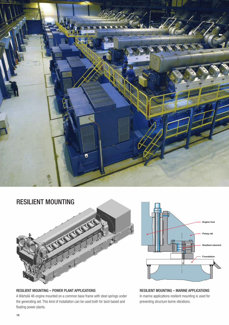
RESILIENT MOUNTING
RESILIENT MOUNTING – POWER PLANT APPLICATIONS RESILIENT MOUNTING – MARINE APPLICATIONS A Wärtsilä 46 engine mounted on a common base frame with steel springs under In marine applications resilient mounting is used for
the generating set. This kind of installation can be used both for land-based and preventing structure borne vibrations.
floating power plants.
14

COOLING SYSTEMS • The fresh water cooling system is devided
into high temperature and low temperature
cooling system.
• The high temperature cooling water system
operates constantly at a high temperature
level to make the temperature fluctuations
in the cylinder components as small as
possible and preventing from corrosion due
to undercooling.
LUBRICATING OIL SYSTEM • Marine engines have dry sump and power
plant engines wet sump. The lube oil is
treated outside the engine by continuous
separating.
• On the way to the engine, the oil passes
through a lube oil cooler, a full flow
automatic filter unit and a safety filter for
final protection.
• For obtaining maximum heat recovery the
charge air cooler is split into a high and low
temperature section.
• Engine driven pumps can be provided as an
option for marine application. In power plant
application, these are standard.
• For the purpose of running-in, provision has
been made for mounting special running-in
filters in the crankcase in front of each main
bearing.
• Engine driven lube oil pump can be
provided as an option for marine
application. In power plant application this
is standard.
15

AUTOMATION SYSTEM The Wärtsilä 46 is equipped with a
modular embedded automation system,
Wärtsilä unified controls - UNIC, which
is available in three different versions.
The basic functionality is the same in all
versions, but the functionality can be easily
expanded to cover different applications.
UNIC C1 and UNIC C2 are versions
applicable for engines with conventional
fuel injection, whereas UNIC C3 additionally
includes fuel injection control for engines
with common-rail fuel injection.
UNIC C1 In the UNIC C1 engine automation system, the
fundamental aspects of the engine control and
safety are handled by the embedded control
and management system. This includes engine
speed and load control as well as overspeed
protection, lube oil pressure and cooling water
temperature protection. For the other parts,
the design requires the majority of the sensors
to be hardwired to an external alarm and
monitoring system.
The following functionality is provided:
• Fundamental safety (overspeed, LO
pressure, cooling water temp.)
• Basic local monitoring
• Hardwired interface to external alarm and
monitoring systems
• Speed and load control
The engine control system
is designed to:
• Achieve the highest possible reliability,
with components, e.g. sensors, designed
specifically for the on-engine environment,
• Reduce cabling on and around the engine,
with a clear point of interconnection and a
standardized interface, and
• Provide high performance with optimized
and pre-tested controls.
16

IOMTCM
LDU
LCP
ESM
MCM
CCM CCM
PDM
Ethernet
Hardwired connections
Loadsh. CAN
LDU
LCP
ESM
MCM
IOM IOM
IOM
PDM
Ethernet
Hardwired connections
Loadsh. CAN
Hardwired connections
LDU
LCP
ESM
MCM
TCM TCM
PDM
Loadsh. CAN
AUTOMATION SYSTEM COMPONENTS
ESM Engine Safety Module
MCM Main Control Module
TCM Thermocouple Module
IOM Input Output Module
PDM Power Distribution Module
LCP Local Control Panel
LDU Local Display Unit
CCM Cylinder Control Module UNIC C1
UNIC C2
UNIC C3
UNIC C2/C3 The UNIC C2 and C3 engine automation
system provides a completely embedded
engine management system, which in
case of common rail fuel injection has
integrated electronic control of the fuel
injection. This is a distributed and bus-
based system in which the monitoring
and control function is placed close to
the point of measurement and control.
This significantly simplifies both the
on- and off-engine wiring. Additionally,
the advanced functions in the system,
e.g. for diagnostics and control, provide
outstanding performance and reliability,
17

18
and the need for off-engine systems is
considerably reduced.
The system meets the highest requirements
for reliability, with selective redundancy and
fault-tolerant designs, and can be applied to
single main engine operation.
The following functionality is provided:
• Complete engine safety system
• Complete local monitoring, including all
readings, events and diagnostics
• Speed and load control
• Complete engine control, including start/
stop, load reduction request, etc.
• Alarm signal provision
• Full system diagnostics
• Fieldbus interface
• Combustion control, EFIC, for diesel or gas
applications
• Redundant control strategies, and fault-
tolerant operation
The engine control system is designed to:
• Provide a compact embedded engine
control and management system for space-
saving applications,
• Reduce installation and commissioning time
by providing a very simple fieldbus-based
interface that is delivered pre-tested and
fully operational from the factory,
• Achieve the highest possible reliability
with components, e.g. sensors, designed
specifically for the on-engine environment,

• Considerably reduce cabling on and around the engine through a
bus-based architecture, with a clear point of interconnection and
with a standardized hardwire and fieldbus interface,
• Provide high performance with optimized and pre-tested controls,
and
• Act as an easy and convenient calibration and service tool for on
line tuning and system diagnostics.
MAINTENANCE During design and development the engine manufacturer emphasizes
the necessity of easy maintenance by including tooling and easy
access in the basic design and by providing easy-to-understand
instructions.
• The Wärtsilä 46 maintenance principle is substantiated by the
following:
• A cylinder head with four fixing studs and simultaneous hydraulic
tightening of all four studs.
• A hydraulic jack for the main bearing overhaul.
• Uniform one-cylinder camshaft pieces.
• Slip-on fittings are used wherever possible.
• Exhaust gas system insulation by using easy-to remove panels on
a frame that is mounted flexibly on the engine.
• The three-piece connecting rod allows inspection of the big end
bearing without removal of the piston, and piston overhaul without
dismantling the big end bearing.
WÄRTSILÄ 46 MAIN TECHNICAL DATA
Ship Power and Ship Power Power Plant engines engines
Cylinder bore 460 mm 460 mm
Piston stroke 580 mm 580 mm
Cylinder output 975 kW/cyl 1050 kW/cyl
Engine speed 500, 514 rpm 500, 514 rpm
Mean effective 25.4, 26.1 bar
pressure 24.3, 23.6 bar 28.0, 28.8 bar
Piston speed 9.7, 9.9 m/s 9.7, 9.9 m/s
Fuel specification:
Fuel oil 730 cSt/50°C
7200 sR1/100°F ISO 8217, category ISO-F-RMK 55
Data for Ship Power engines Rated power
Engine type
500, 514 rpm 500, 514 rpm 975 kW/cyl 1050 kW/cyl
kW bhp kW bhp 6L46 5 850 7 950 6 300 8 565 8L46 7 800 10 600 8 400 11 420 9L46 8 775 11 930 9 450 12 850
12V46 11 700 15 900 12 600 17 130 16V46 15 600 21 210 16 800 22 840
Dimensions (mm) and weights (tonnes)
Engine type A* A B C D F Weight
6L46 8L46 9L46 12V46 16V46
7 580 9 490
10 310 10 260
12 345/12 4601)
8 290 10 005 10 830 10 210
12 480/12 5901)
3 340 3 260/3 6001)
3 600 3 660
3 660/3 9901)
2 880 3 180 3 270
3 810/4 5302)
4 530/5 3501)
3820 3820 3820 3600 3600
1 460 1 460 1 460 1 500 1 500
95 120 137 169 214
* Turbocharger at flywheel end. 1) Depending on output. 2) Depending on turbocharger and output.
Data for Power Plant engines Technical data 50 Hz/500 rpm Unit 12V46 18V46 Power, electrical kW 11349 17076 Heat rate kJ/kWh 7692 7669 Electrical efficiency % 46.8 46.9 Technical data 60 Hz/514 rpm Power, electrical kW 11349 17076 Heat rate kJ/kWh 7692 7669 Electrical efficiency % 46.8 46.9 Dimensions and dry weight with generating set Length mm 15400 18260 Width mm 5090 5090 Height mm 5700 5885 Weight tonne 265 358
Heat rate and electrical efficiency at generator terminals, including engine-driven pumps. ISO 3046 conditions and LHV. Tolerance 5%. Power factor 0.8.
19

05.2
008
/ B
ock´
s O
ffice
/ W
aasa
Gra
phi
cs
Wärtsilä enhances the business of its customers by providing them
with complete lifecycle power solutions. When creating better and
environmentally compatible technologies, Wärtsilä focuses on the
marine and energy markets with products and solutions as well as
services. Through innovative products and services, Wärtsilä sets out
to be the most valued business partner of all its customers. This is
achieved by the dedication of more than 17,000 professionals manning
160 Wärtsilä locations in 70 countries around the world. Wärtsilä is
listed on The Nordic Exchange in Helsinki, Finland.
WÄRTSILÄ® is a registered trademark. Copyright © 2008 Wärtsilä Corporation.


![Journal of Power Sourcesnpt.pusan.ac.kr/sites/npt/download/[46]JPS-2015-HC decomp... · 2018-03-28 · versions of gas-fueled molten carbonate fuel cells (MCFC) or solid oxide fuel](https://static.fdocuments.us/doc/165x107/5f064ade7e708231d417432d/journal-of-power-46jps-2015-hc-decomp-2018-03-28-versions-of-gas-fueled.jpg)
