WORKSHOP PRACTICES - DPHU. PRACTICES. BASIC STEPS. 1. Design concepts. 2. Selection of materials. 3....
80
WORKSHOP PRACTICES
Transcript of WORKSHOP PRACTICES - DPHU. PRACTICES. BASIC STEPS. 1. Design concepts. 2. Selection of materials. 3....

WORKSHOPPRACTICES

BASIC STEPS
1. Design concepts
2. Selection of materials
3. Manufacturing

DESIGN REQUIREMENTS
Objectives to achieve Geometry, Size and finish
Prepare for manufacturing Drawing + Material

• Communication of information Shape, size, and features
• Universal language of engineering
• Graphical construction
DRAWING

Drawing: Interpretation and creation
Dimensioning: Proper communication
Tolerances: Manufacturer’s limits
DRAWING SKILLS

BASIC INFORMATION
• Projected Views: Show as many views showing completeness.(Front, Side, Top, others.)
•Cross Sections:A view that is good for showing interior features.
• DIMENSIONS: Most important

PROJECTIONS(Orthographic representation)
Front,Top, Side Views. Isometric .

GRAPHIC REPRESENTATION
Two-dimensional representation of three-dimensional objects
DIMENSIONS
To build the structure or fabricate parts
Simple Object 1 Simple Object 2
60 40
30
+ + + +
+ + + +
+ +
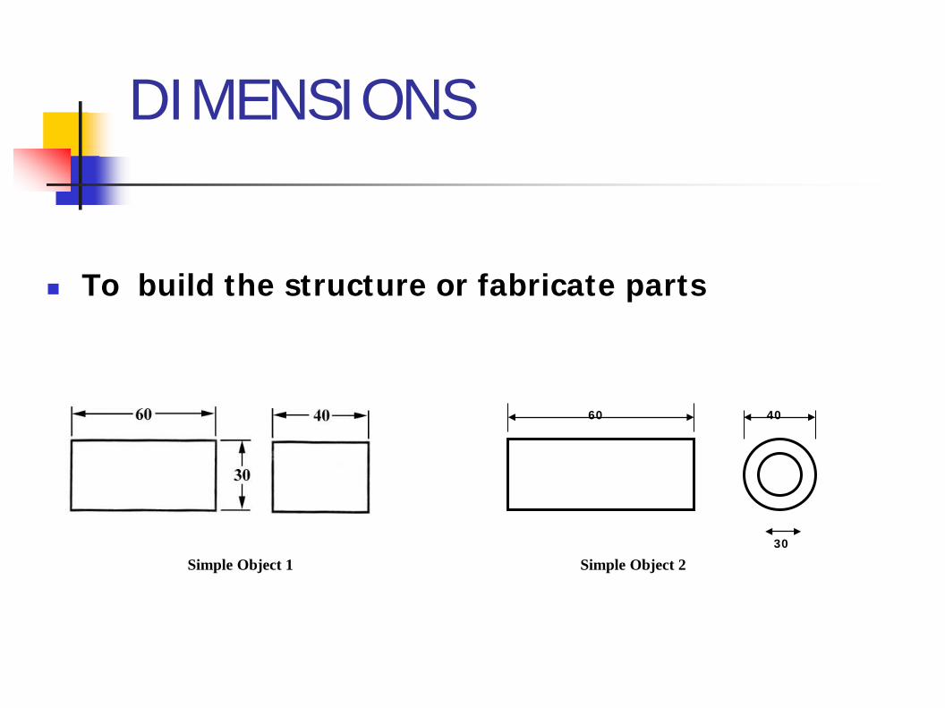
Parallel Dimensions Chain Dimensions
Super imposed Dimensions
Combined Dimensions
Co ordinate Dimensions
DEFINING DIMENSIONS

DIMENSIONING FEATURES
CirclesHoles
Radii
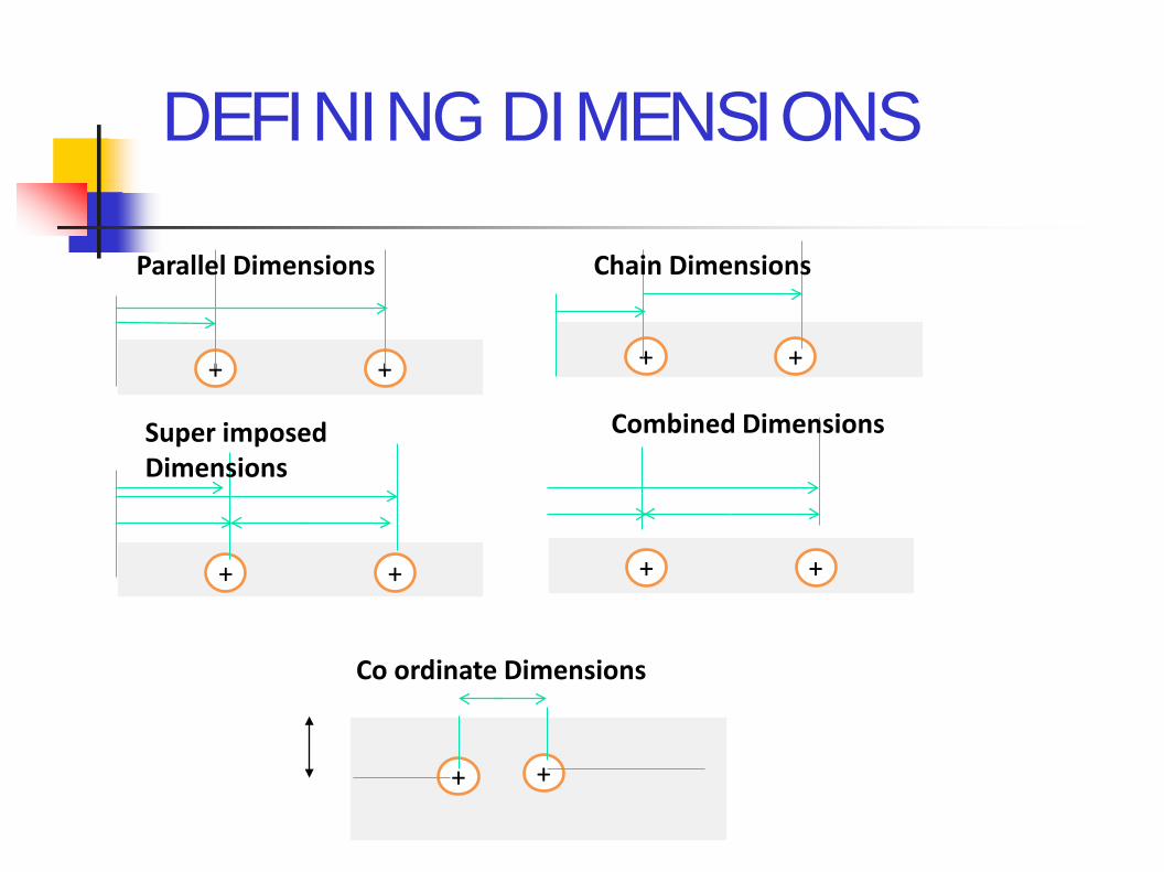
TOLERENCES
Dimensional Tolerances +-
Geometric Tolerances
The maximum permissible variation from the dimension

TYPES OF DRAWINGS
Layout - Placements
Working - Assembly parts Schematic/
diagrammatic - Using symbols

PRODUCING DRAWINGS
Manual or with drawing instruments and Other aids such as templates and appliqués,
Free hand with pencil on paper or with automated devices like computers.

Hand Drawing
Pencils Pens/Inks Chalk Crayons Drawing Papers and Surfaces Drawing Tools and Accessories Erasers

Drawing Tools and Accessories
Compasses Curves Drawing Boards Lettering Stencils and Guides Parallel Rules Protractors, Triangles, and Corner Squares Rulers and Measurement Tools T-Squares Templates

MODERN AIDS
Computer Software
Computer Aided Design - CAD

SELECTION OF MATERIALS

Classification of MaterialsBased on the specific application
Structural materials (mechanical parts)
Functional materials (electrical, optical,magnetic, ...)
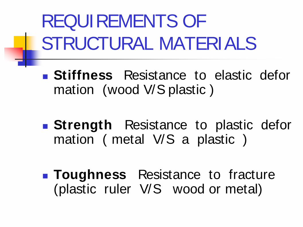
REQUIREMENTS OF STRUCTURAL MATERIALS
Stiffness Resistance to elastic deformation (wood V/S plastic )
Strength Resistance to plastic deformation ( metal V/S a plastic )
Toughness Resistance to fracture(plastic ruler V/S wood or metal)

Electrical materialsConductors, insulators, dielectric …
Magnetic materialsRemanence, saturation magnetization …
Optical materialsTransmission, reflection, refraction
REQUIREMENTS OFFUNCTIONAL MATERIALS
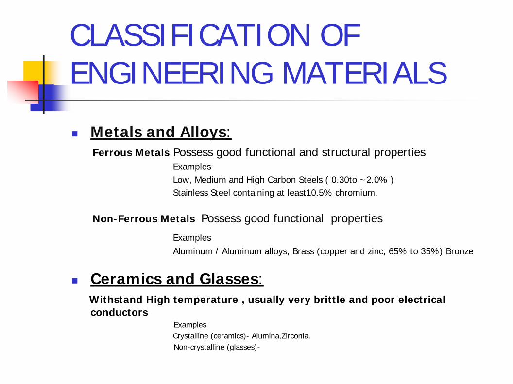
CLASSIFICATION OFENGINEERING MATERIALS
Metals and Alloys:Ferrous Metals Possess good functional and structural properties
ExamplesLow, Medium and High Carbon Steels ( 0.30to ~2.0% ) Stainless Steel containing at least10.5% chromium.
Non-Ferrous Metals Possess good functional properties
ExamplesAluminum / Aluminum alloys, Brass (copper and zinc, 65% to 35%) Bronze
Ceramics and Glasses:Withstand High temperature , usually very brittle and poor electrical conductors
ExamplesCrystalline (ceramics)- Alumina,Zirconia.Non-crystalline (glasses)-

ENGINEERING MATERIALS Polymers: Non-crystalline Organic materials containing carbon.
Most polymers are poor electrical conductors but corrosion resistant.ExamplesThermoplastic. Formed into desired shapes under heat and pressure.(PVC), polycarbonate (PC), and polystyrene (PS). polyethylene (PE), polypropylene (PP), polyesterThermosetting materials. Formed into desired shapes under heatExamples
Composites: High stiffness, High strength and High temperature performance
Materials where two or more of the above materials are brought together on macroscopic level. Usually they consist of a matrix and a reinforcement.
Example
Metal-matrix composites (MMC) Polymer-matrix composites (PMC) Ceramic-matrix composites (CMC)

Alkali metals
Alkaline earths
Non Metals
Gases
MetalloidsMetals

MATERIALS SELECTIONCRITERIA
1. Engineering considerations( Strength, durability..)
2. Cost 3. “Green” ? 4. Easy commercial availability5. Political (Sanctions on nuclear materials)
6. Technology (Cryogenic engines, ….)

Materials property charts
Image courtesy: University of Cambridge homepage

Manufacturing

MANUFACTURING PROCESSES
Melting & Casting Bulk forming Machining Sheet Metal Forming Joining
MELTING & CASTING
The first step in manufacturing.
In casting, a material in liquid form is poured into a mold where it is allowed to solidify by cooling (metals) or by reaction(plastics).
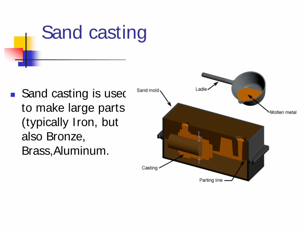
Sand casting
Sand casting is used to make large parts (typically Iron, but also Bronze, Brass,Aluminum.

Shell Mould Casting

Die-casting
In Die-casting the metal is injected into the mold under high pressure

Centrifugal Casting

Investment Casting

Bulk Forming
Rolling
Forging
Extrusion Drawing

Various Mills
A small rolling Mill A Hammer MillAn extrusion Mill

Machining
• The process of removing material from a work piece in the form of chips
• A machining process requires a cutting tool & a machine

Machining Processes
Turning Milling Drilling Shaping / Planing. Sheet Metal Forming Joining

Turning
Turning is performedon a lathe machine
Turning Facing
partingThreading Groving

Definition of a Lathe Machine
Bed
Chuck
Tail stock
Tool post
Head stock

Parts of a Lathe Machine

Head Stock

Carriage

Tail Stock
www.machinetoolsupplier.com

A CNC Lathe Machine

Milling
Milling is a widely-used for producing slots
Face milling
Reaming

A SIMPLE MILLNG MACHINE
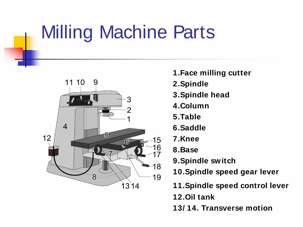
Milling Machine Parts
1.Face milling cutter2.Spindle 3.Spindle head4.Column 5.Table 6.Saddle 7.Knee 8.Base 9.Spindle switch 10.Spindle speed gear lever
11.Spindle speed control lever12.Oil tank 13/14. Transverse motion

Milling Tools

CNC Milling Machine
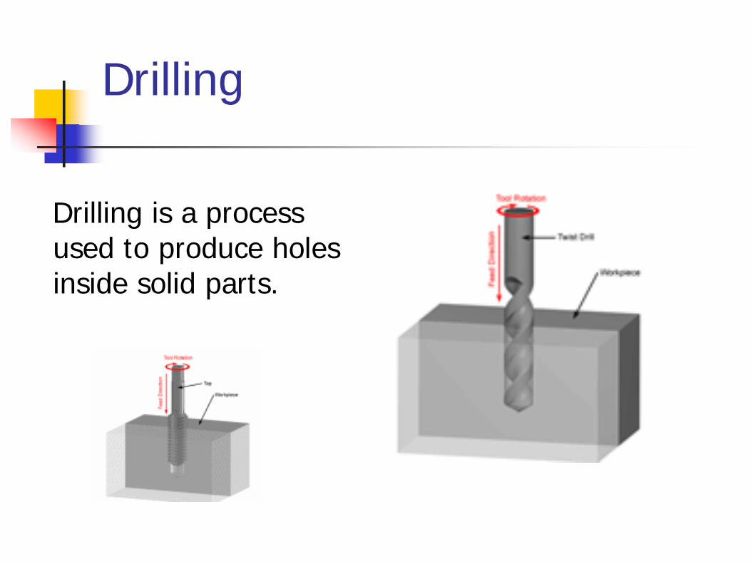
Drilling
Drilling is a process used to produce holes inside solid parts.
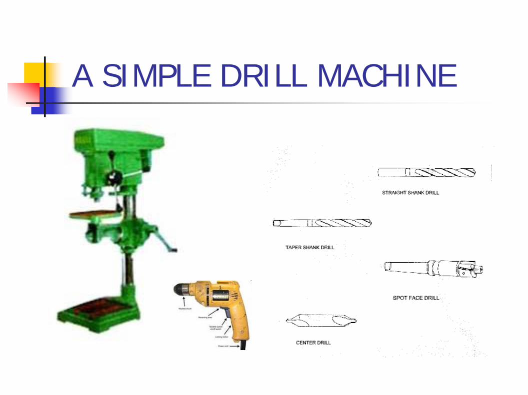
A SIMPLE DRILL MACHINE

Shaper machine

Shaping Machine
Shaping is used to produce surfaces.

Sawing
Cutting process
Wood
Metal
Glass

Sawing Machines
Hack Saw Band Saw

Abrasive Saw
Abrasive cut off saw

Grinding
Centreless Grinding
Grinding Wheel
Surface Grinding
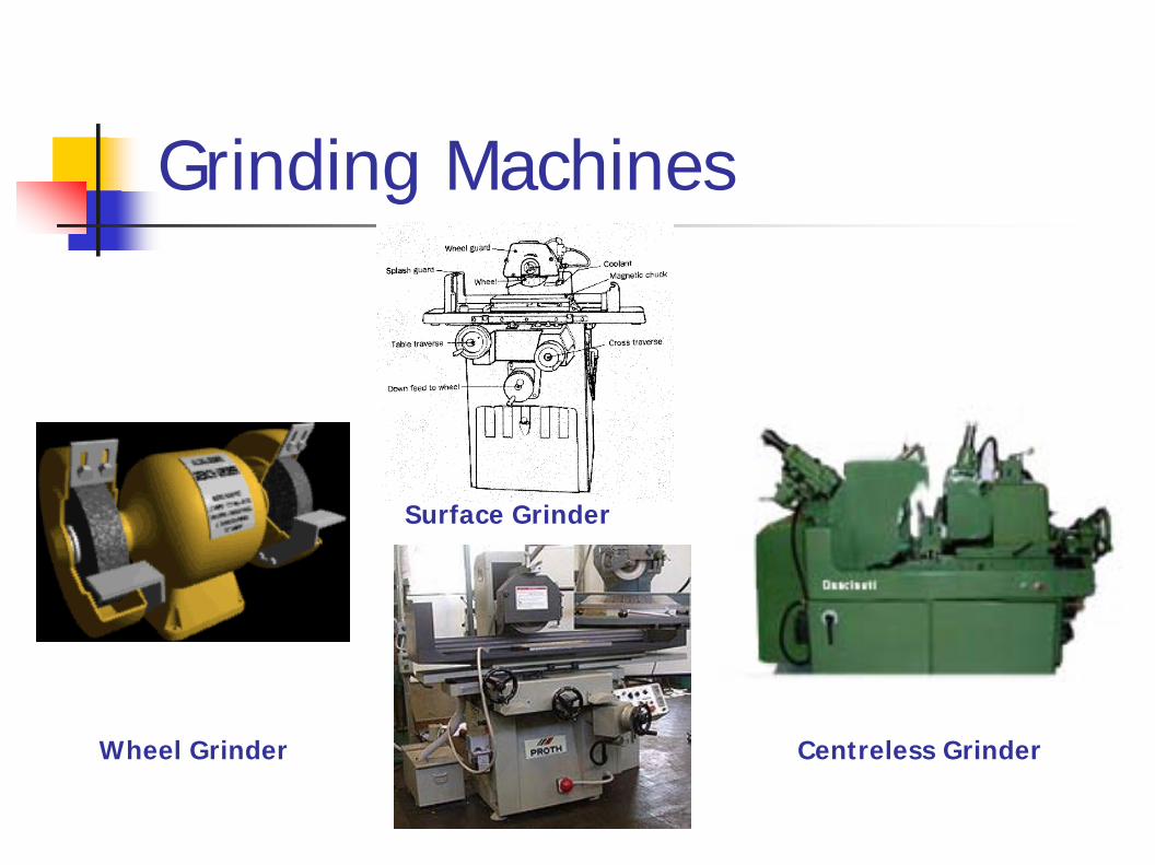
Grinding Machines
Centreless GrinderWheel Grinder
Surface Grinder

Sheet Metal Forming
An important manufacturing process
Sheet bendingSheet cutting
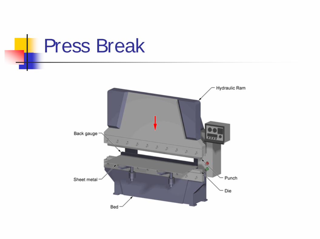
Press Break

Sheet Metal Forming & drawing
Forming
Sheet Bending
Deep Drawing

Welding
Permanently joining metal parts
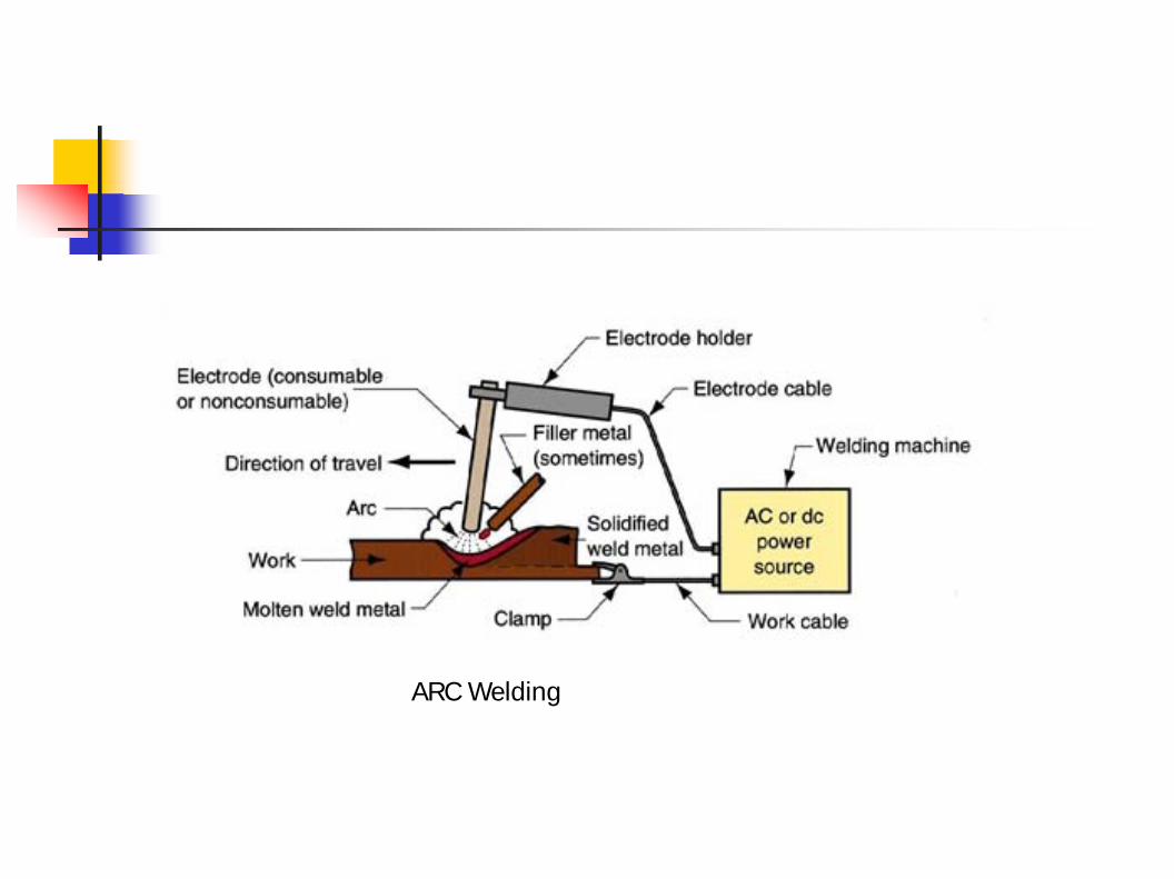
ARC Welding

Oxy Fuel Welding
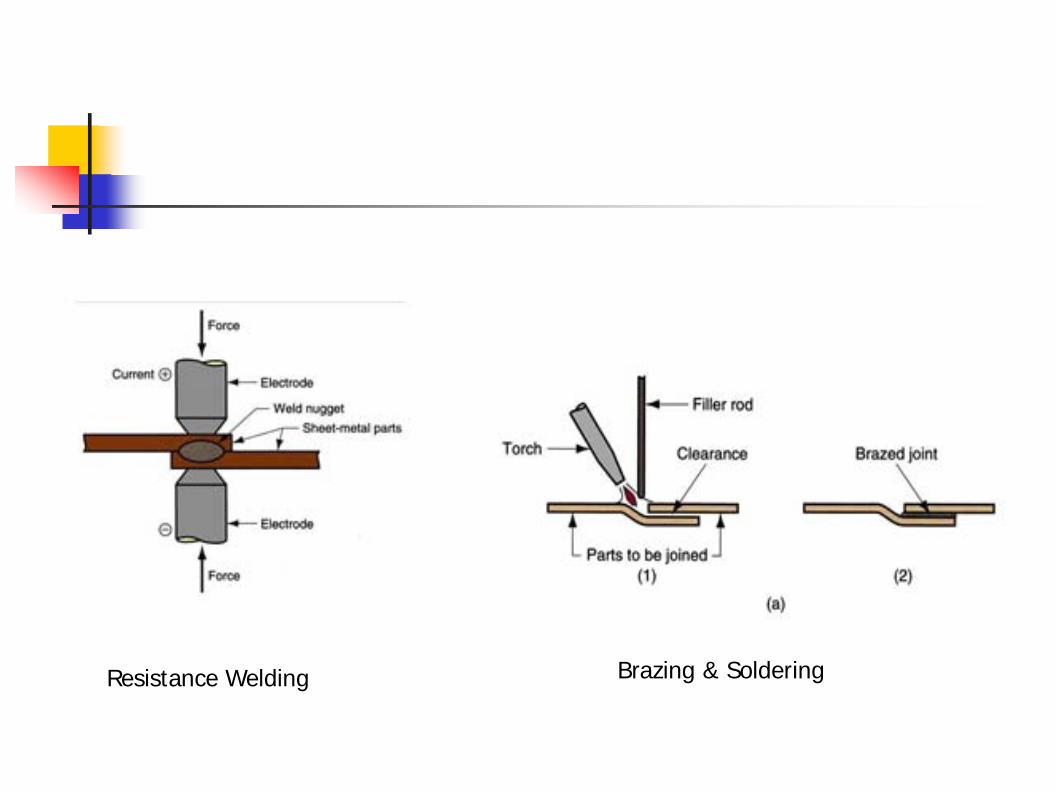
Resistance Welding Brazing & Soldering

LASER PROCESSING
END SLIDE

Testing of Materials

Historical interest● Mohs
Macro tests● Brinell● Rockwell
Micro tests● Vickers● Knoop● Nanoindentation
Measuring harndess

Mohs scale
Mohs scale 1 Talc
Mohs scale 2 ● Gypsum
Mohs scale 3 Calcite
Mohs scale 4 Fluorite

Mohs scale
Mohs scale 5 Apatite
Mohs scale 6 Feldspar
Mohs scale 7 Quartz
Mohs scale 8 Topaz

Mohs scale 9 Corundum
Mohs scale 10 Diamond

● 10 mm dia steel ball
●29 kN force (3000 kgf)
● Softer -less force ●
Harder -Tungsten carbide ball
Brinell hardness

Rockwell hardness
●
Brinell is not trulynondestructive test ● Rockwell -a minor load and
then a major load;
note the depth ofpenetration; read th

StrengthDensity chart

Stiffness—Strength (specific) chart

Textbook
●
Mateials: engineering,science, processing and design,M F Ashby, H Shercliff and D Cebon, Butterworth inemann, 2007

A stadard cell in a chip● Rendering of a small standard
cell with three metal layers (dielectric has been removed).
The sandcolored structures are metal interconnect, with the vertical pillars being contacts, typically plugs of tungsten.The reddish structures arepolysilicon gates, and the solid at the bottom is the crystalline silicon bulk.
●
Image courtesy: wiki (David Carron)
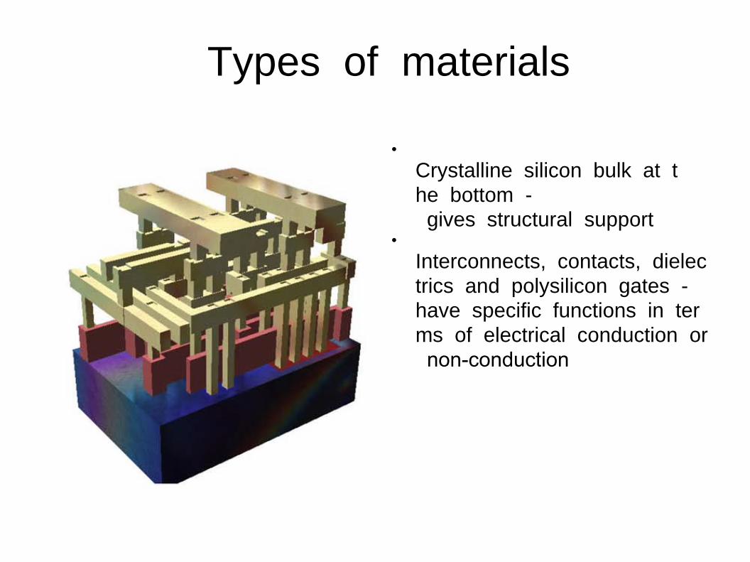
Types of materials
●
Crystalline silicon bulk at the bottom -gives structural support
●
Interconnects, contacts, dielectrics and polysilicon gates -have specific functions in terms of electrical conduction ornonconduction