Worcester Controls CPT Series Characterized Seat Control Valve ...
32
Experience In Motion Worcester Controls CPT Characterized Seat Control Valve Customized Control for Severe Throttling Services
Transcript of Worcester Controls CPT Series Characterized Seat Control Valve ...

Experience In Motion
Worcester ControlsCPT Characterized Seat Control Valve
Customized Control for Severe Throttling Services

�
After years of research and performance evaluation under severe throttling services, where precise computer control was required, Flowserve Worcester Controls has developed the CPT characterized seat control valve series. These valves exceed the performance features of traditional linear valves, as well as that of segmented ball and eccentric plug designs.
The CPT characterized seat control valve is a ball valve, but that’s where the similarity ends. The control capacity is defined by a revolutionary seat technology. These seats consist of a sintered stainless steel material that has been fully impregnated with TFE or Graphite, then laser-cut to a customized shape to best suit the individual application.
Combine these capabilities with Flowserve’s high-cycle pneumatic, electric, or electro-pneumatic actuators, positioners, and accessories, and you have a control valve package that will meet the performance capabilities available with computers and PLC controllers.
The Series CPT Characterized Seat Control Valve is a high technology, final control element that matches the performance of computers and PLCs.
• Precision control • Tight shutoff–bubbletight
• Zero external leakage • Low maintenance, few parts
• High cycle capability • Compact design, light weight
• Interchangeable characterized seats • High flow capacity
• High rangeability (turn down) • Energy efficient
• Efficient shearing action for solids and fibers
Flowserve Worcester CPT Characterized Seat Control Valves

flowserve.com
�
Advanced Control TechnologyLook beyond traditional globe control valves to a valve technology that gives you high pressure drop capability with straight-through flow, precision control, shearing action, erosion control and bubbletight shutoff. This technology is the CPT’s self-lubricated, full contact seat of sintered stainless steel impregnated with TFE or graphite. The flow characteristic is laser cut to a “V” shape, slots, or custom-ized shapes to meet any control requirement. The V-shaped port is available in seven standard angles for equal-percent characteristic with capacity closely matched to system needs. The lubricating action of the special coating on the ball and TFE or graphite impregnation throughout the thick-ness of the characterized seat results in amazingly smooth, stable throttling control.
The characterized seat design allows use of exotic materials such as Inconel 600®, Hastelloy C22®, Stellite 6 or Monel®.
FM Oil and Gas Safety ShutoffThe 1/4"–2" CPT 44 series valves and 1/2"–4" CPT 51/52 valves with Pulsair III are approved by Factory Mutual for oil and gas safety shutoff service and flow control. For further information, contact the Custom Products Department.
Standard ∆P CapabilitiesLiquids to 500 psi
Steam to 300 psi
�16 sintered metal seats are impregnated with TFE or graphite to provide positive shutoff and lubrication when contacting the hard coated ball.
Characterized Seats with Metal A (TFE impregnation) or Metal G (graphite impregnation) are available in sizes ¼"–4".

4
The characterized seat control valve gives you extremely accurate control through the entire valve stroke with seat openings designed specifically for your process. This design means efficient, straight-through flow, rotary shaft sealing and bubbletight shutoff.
The seat design makes a throttling control valve that is both forgiving and accommodating. If a valve is sized incorrectly or if process conditions change, you can change the Cv and/or the control characteristic by merely changing out the seat.
At last! A control valve that shuts off bubbletight. The floating ball concept and Worcester Controls proprietary metal CPT seat design allows the valve to be bi-directional and still exceed ASME Class VI shutoff. The unique design of the Worcester CPT utilizes both a 316 stainless steel metal seat and a resilient seat, allowing for less operating torque than traditional ball control valves.
Flowserve recommends that the CPT seat be located in the downstream position in applications where the potential for erosion exists so any potential damage will occur away from the valve body. This is a major improvement in applications where damage by erosion in the valve body has been an expensive and time consuming problem.
A High Pressure Drop Control Valve with Custom Characteristics and Bubbletight Shutoff
Control Valve Sizing SoftwareFlowserve Performance! Software is now available to support your applications and project activities. Order your copy of Performance! today! For more information, or to download a trial version, go to http://performance.flowserve.com.
1 � � 4
1
4
2
3
5
Cv
% Open
Simple changeout of the seat permits change of valve characteristic to match your process requirements.
Virtually Limitless Seat DesignsThe V-shape of the standard seat (1) in CPT characterized seat control valves is precision laser cut and offers inherent modified equal percentage flow characteristic. Slotted seat valves (3) have inherent linear flow characteristics. If your requirements are different, we change the seat cut. Seats with multiple ports and custom openings (2, 4, and 5) are available to meet your unique control needs.
Flowserve offers the CPT Vee-Twin for more severe applica-tions. The Vee-Twin design combines two CPT seats into one body for staged pressure reduction. This results in better resistance to cavitation and reduced noise.
In addition to providing excellent resistance to cavitation, the dual Characterized V-port seats are not subject to fouling like conventional anticavitation trims that utilize many small holes. The Vee-Twin allows relatively large particles to pass through the valve, and the shearing action of the ball against the seat slices off fibrous contaminants and cleans the seating surface in every cycle.
Seat leakage is less than allowed by ANSI Class IV. The Vee-Twin option is available on all versions of the CPT, but special actuator sizing applies. Refer to page 22 for actuator sizing data and for flow coefficients, refer to page 20.
Vee-Twin Valves for the Most Severe Applications
• Characterized seat
• Resilient or round metal seat
The characterized seat control valve is a bi-directional valve.

flowserve.com
�
Complete Piping Versatility One Control Valve, Six Valve Configurations, Hundreds of CharacteristicsThe CPT control valve is not locked into one body style. Now you can choose a characterized seat control valve for the compactness of skid-mounted systems, the ruggedness of flanged piping, the high pressure integrity of welded systems, and the leakproof containment of sterile fluids*, cryogenics*, and chemicals in the EPA’s Toxic Release Inventory.
Valve Configuration
Cryogenic design, Three-piece (shown) or flanged
Model
C44, C51/C52
Sizes
1/4", 1/2", 3/4", 1", 1/2", 2", 3", 4"
Pressure Rating
1000 psi max.
End Connections
Screw end, socket weld, butt weld, ASME Class 150 or 300 flanges
Valve Configuration
Wafer
Model
CPT 151, CPT 301
Sizes
3", 4"
Pressure Rating
ASME Class 150, ASME Class 300
End Connections
Wafer – for use between ASME Class 150 or Class 300 flanges
Valve Configuration
Flanged
Model
CPT 51, CPT 52
Sizes
1/2", 3/4", 1", 11/2", 2", 3", 4"
Pressure Rating
ASME Class 150, ASME Class 300
End Connections
ASME Class 150 or Class 300 raised face flanges
Valve Configuration
Three-piece
Model
CPT 44
Sizes
1/4", 1/2", 3/4", 1", 1/2", 2"
Pressure Rating
1000 psi max.
End Connections
Screw end, socket weld, butt weld
Valve Configuration
Anti-fugitive emission three-piece
Model
CPT 94
Sizes
1/4", 1/2", 3/4", 1", 11/2", 2"
Pressure Rating
1000 psi max.
End Connections
Screw end, socket weld, butt weld
Valve Configuration
Anti-fugitive emission flanged
Model
CPT 94
Sizes
1/2", 3/4", 1", 11/2", 2", 3", 4"
Pressure Rating
ASME Class 150, 300, 600
End Connections
Raised face flanges
* Characterized seat clean valves and cryogenic valves are available through Flowserve’s Custom Products Department.

6
Advanced Stem Design for Low Hysteresis, High Repeatability and Leak-Free, Stick-Free, High-Cycle OperationFlowserve Worcester Controls CPT characterized seat control valves represent a profound improvement over traditional globe and rotary valves that use heavy linear actuators, crank arms, and associated linkage. Worcester Controls has eliminated significant hysteresis and assured repeatability by powering through a solidly clamped, in-line stem. All shafts operate together: actuator, positioner, valve stem. The design also eliminates side load on the valve stem because components (valve, actuator, positioner) are mounted symmetrically and forces are balanced. This extends valve seal life far beyond conventional valves.
High-Performance Stem SealsA new stem seal design, consisting of PEEK and Polyfill® thrust bearings and seals, significantly increases valve cycle life over conventional control valves and extends time between adjustments. The stem seal is live loaded to compensate for wear or thermal effects. Valve action is rotary. This means that toxic fluids, flammable fluids, and fluids that tend to crystallize or oxidize upon contact with atmosphere are fully contained and do not inhibit the freedom of motion of the valve.
Stem Seals for EPA RequirementsFor an extended leak-free process environment, extended temperature application, and to meet EPA requirements, Worcester Controls offers the CPT 94 Control Valve. The Series CPT 94 valve is a NACE compatible, rugged, throttling ball control valve for fluids such as chlorine, phosgene, and many toxic liquids and gases. All Worcester Controls standard and characterized seats are available in this valve configuration. The heart of the Series 94 valve is a large diameter stem with double, live-loaded seal, and a Lantern-Ring connection. The connection may be used to detect and channel unlikely leakage from the primary seal, or may be used to create a liquid/gas seal for the stem, or for a steam purge to provide a sterile packing. A second connection is optional. Seal loading is kept constant with a series of Belleville washers. The standard seal consists of a TFE box ring with TFE V-ring packing. Graphite packing is optional.
Direct Shaft Position Feedback
NAMUR Interface
Matched Ball and Stem Connection
Clamped Couplings
Standard high-cycle, live-loaded, high-performance stem seal
Series CPT 94 high-cycle, anti-fugitive emission stem seal
High Strength Stem
Live-Loaded Stem Seal

flowserve.com
�
Applications
Controlling steam pressure is not easy. Typical problems associated with globe control valves in steam service have been stem leakage, sticking, poor shutoff, and high maintenance. Linear stem valves require frequent packing adjustment and over-tight packing may create added stem friction that could cause controller instability. Furthermore, Class V, IV, or III shutoff is usually too much leakage for many applications requiring tight shutoff.
Worcester Controls characterized seat valves solve these problems with tight shutoff exceeding Class VI. Self-compensating rotary stem seals and tailored seat characteristics provide a ramp-up condition quickly while maintaining precision low-flow control. Thousands of CPT valves are successfully operating in steam systems where globe valves were originally used. A typical user reaction: “We are removing our globe valves and replacing them with Worcester Controls characterized seat control valves because they work better and control better.”
Toxic FluidsTraditional rising stem globe valves cannot stand up to the demanding specifica-tions implemented by the EPA, OSHA and other regulating agen-cies. The very nature of the design, even with double packing and/or bellows seals have relatively short cycle lives compared to rotary seals. The Series CPT 94 control valve shown on page 6 has been certified by third party testing, allowing less than 25 ppm leakage, whereas EPA requirements are 500 ppm. Self-adjusting stem seals with multiple Belleville washers make this valve ideal for throttling toxic chemicals.
pH ControlLow flow rates associated with pH process control loops require valves with very small openings. This creates a major problem in traditional rising stem control valves if any solids larger than the valve opening are in the system. Unfortunately, in most pH systems, it is impossible to eliminate solids in the liquid stream. They often clog control valves. This results in having to shut the line down and disassemble the valve for cleaning.
The CPT is the ideal control valve for pH control when using a low flow opening and solid removal hole. The special opening of the pH control seats, shown, provide the most ideal throttling characteristics and turndown while allowing solids to move out of the larger opening. Also, erosion problems are minimized and the valve body is protected since the vena contracta is located outside the valve body.
Steam Control

�
ApplicationsCryogenicsCompactness, balanced weight, precision control, tight shutoff, and long service life are features considered unique and unmatched by conventional control valve designs and styles. The cryogenic characterized seat valve is also designed to handle large temperature swings with its special seats and self-compensating rotary stem seal design. All this has made CPT an ideal control valve for low temperature and cryogenic applications such as freezing systems, lyophilization systems, high-purity gas systems, terminal loading stations, over-the-road CO2, LNG food carriers, and air separation systems. The characterized valve provides tailored flow characteristics for each process—in the body and trim materials you require. CPT valves can be easily and economically controlled by Worcester Controls Series 39 pneumatic or Series 75 electric actuators.
The heart of our pneumatic automation package is the Series 39 actuator. A Worcester Controls innovation, the Series 39 is an accurate, compact, powerful, double-piston, rack-and-pinion actuator with an impressive track record for reliability. That’s why we back it with an exclusive two-year warranty. One plant reported 14 million complete cycles without appreciable original seal wear.
Piston tilting is prevented due to unique guide rods that always keep the pistons parallel with each other and perpendicular to the cylinder. This feature enables the Series 39 actuator to match the performance of diaphragm actuators in terms of high resolution. Internal friction is reduced with a nickel acetate-coated cylinder, low coefficient-of-friction acetal resin bearings and a special permanent lubricant with corrosion inhibitors.
Worcester’s control valve packages are designed to func-tion with virtually no inherent hysteresis, an important feature in throttling control. Precision parts within the Series 39 actuator permit very high torque performance with minimum backlash.
Series �� Actuator Presenting the ultimate actuator package for electronic process control: the Series 75. Ideal for analog or digital controlled systems where pneumatic control is neither possible nor desirable.
The Series 75 actuator adds a new dimension of operational dependability and flexibility to modern processes controlled by computers and programmable logic controllers. It is compact and powerful. Its brushless, split phase capac-itor, start/run reversing AC motor or rugged and powerful DC motor, drives the valve through a permanently lubricated gear train which offers virtually lifetime maintenance-free, dependable operation. Precision throttling control is achieved by a choice of electronic positioners and controllers that can work with digital or analog control loops. A variety of options allow you to select the performance criteria, diagnostic data and feedback information you desire.
Series �9 Actuator

flowserve.com
9
New Technology – Positioners and Accessories
Now is your opportunity to stop oscillation or hunting in your process. Most process control loops are unstable due to an improper valve characteristic, positioner characteristic or both. The Worcester Controls CPT characterized seat control valve with either the Pulsair III or DataFlo positioner puts a permanent stop to these problems. It is done by tailoring the characterized seat opening and free character-
istic curve of the positioner for each process loop. Install our control valve package in any of your flow, temperature, pressure, vacuum or other demanding or critical control applications and find out how our new technology can give you the precise control you have always looked for but couldn’t achieve with traditional control valves and positioners.
Cv
Valve Rotation
100
60
40
0
0% 30% 80% 100%
20 mA18 mA
6 mA4 mA
0% 50%Set Point
70% 100%
20% Cv change for 50% valve rotation is a tailored CPT valve characteristic. Result is 0.1°F control of temperature or 0.1 psi pressure control.
Above free tailored characteristic programmed in Pulsair III or DataFlo uses 75% of the available signal to move the valve around the set point position by only 20%.
For pneumatically actuated control valves
The Pulsair III loop-powered valve positioner with auto calibration and zero air bleed is a totally new concept in pneumatic control valve positioning. Operated and controlled by a 4–20 mA analog signal, Pulsair III is microprocessor-based with piezoelectric valves. Air is pulsed to the actuator pistons, eliminating constant air bleed and providing very accurate positioning without overshoot. With a 100-plus-function menu and a five-button keypad, you can automatically calibrate the positioner, change valve action, split range, modify the control characteristic and select many other control parameters. Intrinsically safe option available. Ask for brochure FCD WCABR1019.
For electrically actuated control valves
The DataFlo P™ Positioner, controlled by a 4–20 mA analog signal from a PLC or digi-tally from a computer, gives you calibration, monitoring and diagnostics both on-site or from a control room computer. This dramatically increases system dependability and lowers valve calibration, monitoring, and maintenance costs.
An electronic positioner with a built-in microcontroller for precise process control
DataFlo P controls your process better and turns your final control element into an efficient digital communications platform. Standard PM15 positioners are offered for 3–15 psi pneumatic control and AF17 positioners for analog control of electrically actuated control valves. Refer to brochures FCD WCABR1032 and FCD WCABR1000.
Flowserve offers all the accessories you need for precise control valve positioning and position feedback.
Through-cover display XP enclosure
SMART POSITIONER
®
Three-button keypad for on-site calibration and functional setup

10
New Technology – Direct Process ControlThe DataFlo C™ controller is a fresh approach to PID control. This combination microcontroller-based PID single-loop controller and final control element brings control to the point of use. The rugged compact package simplifies wiring requirements by directly accepting RTD, analog or thermocouple inputs.The signal does not have to be conditioned, improving reliability. All the parameters are easily programmable through the local keypad or via a simple RS-485 computer interface. The control valve/PID controller is easily tuned to the loop with the built-in auto tune program (excluding level control). Refer to brochure FCD WCABR1021.
PC/PLC/Computer Interface and Manual Valve Control
Remote interface capability allows the user to monitor their process and change the controller settings. An additional feature allows the user to take the controller off-line and operate in a manual positioning mode. The user can switch
between PID control and a linear positioning mode by a discrete 24 VDC output from the PLC. An operator can also change set point input via an analog input to the controller.
RS-485OPTIONAL
PC/PLC
VALVE
SENSOR
SENSORDATA TRANSMITTER
SET-POINT
SET-POINTCONTROLLER
Process Control SolutionsLCV-1: Level control – differential pressure
DataFlo supervisory controller (process interface)
FCV-2: Flow control (tank discharge) – flow meter DataFlo supervisory controller (process interface)
PCV-3: Pressure control (pump bypass) – pressure transducer DataFlo remote controller (process interface)
DRC4–20 mA
FeedbackPCV-3
FCV-2
LCV-1
PUMP
REMOTESTORAGE TANK
4–20 mA
RS-485
RS-4
85
DSC
PRIMARYSTORAGE TANK
4–20
mA
DP
FM
P
DRC/DSCFlowserve introduces two new products that allow the customer the capability to control and monitor their process control valves from a remote location.
The DataFlo Remote Controller (DRC) is specifically designed to interface with electrically actuated control valves. This combined positioner-controller accommodates multiple I/O options for both set point and process inputs. Performance monitoring and maintenance diagnostic data is available locally for “real time” user interface and remotely for predictive maintenance programs. The DRC is packaged in a NEMA 4X enclosure and features a splash-proof keypad and bright alphanumeric LED display for user-friendly interface.
The DataFlo Supervisory Controller (DSC) is designed to interface with multiple process control valves via a two-wire fieldbus network. The DSC provides interface process control and performance monitoring for a maximum of 31 process control loops. (Performance monitoring and maintenance diagnostic data is available locally for “real time” user interface and remotely for predictive maintenance programs.) The DSC is packaged in a NEMA 4X enclosure and features a 16-key splash-proof keypad and four-line “avionics” grade LED display for user-friendly interface. The DSC is a cost effective solu-tion that eliminates expensive traditional “PLC” type systems with central control and point-to-point wiring.

flowserve.com
11
CPT 51/52 Flanged Control Valves
Valve Size: 1/2", 3/4", 1", 11/2", 2", 3", 4"
Valve Pressure Class:CPT 51 – ASME Class 150 flanges CPT 52 – ASME Class 300 flanges
Body and End Plug Materials:Carbon steel, 316 stainless steel Other materials available upon request.
Stem Seal Assembly:PEEK and Polyfill (1/2"–2") Refer to Series 51/52 brochure.
Maximum Valve Temperature: 650°FFor higher temperatures consult Flowserve.
C44, C51/C52 Cryogenic Control Valves
Valve Size: 1/4", 1/2", 3/4", 1", 11/2", 2" (three-piece valves) 1"–4" flanged valves
Valve Pressure Class:ASME Class 600 (This is the body pressure rating.) Seat selection may derate the valve.
Body and Pipe End Materials:Carbon steel, 316 stainless steel Other materials available upon request.
End Connections:Screw end, socket weld, butt weld
Stem Seal Assembly:PEEK and Polyfill — Refer to Series 44 brochure.
Maximum Valve Temperature: 600°FFor higher temperatures consult Flowserve.
CPT 44 Three-Piece Control Valves
Valve Size: 1/4", 1/2", 3/4", 1", 11/2", 2"
Valve Pressure Class: ASME Class 600 (This is the body pressure rating.) Seat selection may derate the valve.
Body and Pipe End Materials: Carbon steel, 316 stainless steel Other materials available upon request.
End Connections: Screw end, socket weld, butt weld
Stem Seal Assembly:PEEK and Polyfill — Refer to Series 44 brochure.
Maximum Valve Temperature: 650°FFor higher temperatures consult Flowserve.
CPT 151/301 Wafer Control Valves
Valve Size: 3" and 4"
Valve Pressure Ratings: To ASME Class 150 and 300
Body and End Plug Materials: Carbon steel, 316 stainless steel
Stem Assembly: PEEK and Polyfill — Refer to Wafer Ball Valve brochure.
Maximum Valve Temperature: 650°FFor higher temperatures consult Flowserve.
CPT 94 Three-Piece and Flanged Control Valves
Valve Size: 1/4", 1/2", 3/4", 1", 11/2", 2" – three-piece valves 1/2", 3/4", 1", 11/2", 2", 3", 4" – flanged valves
Valve Pressure Class:ASME Class 600 – three-piece valves ASME Class 150 and 300 – flanged valves
Body and Pipe End or End Plug Materials: Carbon steel, 316 stainless steel
Stem Assembly:Dual stem seal of TFE and/or Grafoil, 35% carbon-filled TFE or Grafoil — Refer to Series 94 brochure.
Maximum Valve Temperature:600°F with Metal “A” characterized seat 800°F with Metal “G” characterized seat
SpecificationsCharacterized Seat Control Valves

1�
Pres
sure
in p
sig
(kPa
)
Three-piece C.S. and 600# flanged
Metal “A”
High-per Fill
Metal “G”
Three-piece S.S. and 600# flanged
Flanged C.S. 300#
Flanged C.S. 150#
Flanged S.S. 150#
(0) -20 100 200 300 400 500 600 700 800 (-29 ) (38 ) (93 ) (149 ) (204 ) (260 ) (316 ) (371 ) (427 )
TFE
Flanged S.S. 300#
Polyfill
1500 (10346)
1000 (6897)
500 (3449)
0
Media Temperature in °F (°C) * For applications above 650°F, use Series CPT 94 valve.
Series 44, 4, �1/��, 1�1/�01 Pressure/Temperature Ratings*
Series CPT 94 Pressure / Temperature RatingNOTES: Body seals have pressure/temperature ratings that equal or exceed the rating of the seat. TFE body seals will not withstand thermal cycles in excess of 200°F.
-20 100 200 300 400 500
Three-piece S.S. and 600# flange
Polyfil
Three-piece C.S. and 600# flange
TFE UHMWPE
R TFE
-20 100 200 300 400 500 600 700 800
Three-piece C.S. and 600# flange
Metal "A"
High-per Fill
Metal "G"
Three-piece S.S. and 600# flange
Pres
sure
in p
sig
(kPa
)
Flanged C.S. 150#
Flanged S.S. 150#
Flanged C.S. 300#
Flanged S.S. 300#
Flanged C.S. 300#
Flanged S.S. 300#
Flanged S.S. 150#
Flanged C.S. 150#
1500
1000
500
0 (0)
1500(10346)
1000 (6897)
500 (3449)
0
(-29 ) (38 ) (93 ) (149 ) (204 ) (260 ) (316 ) (371 ) (427 )
Maximum Temperature in °F (°C)
(-29 ) (38 ) (93 ) (149 ) (204 ) (260 )
Maximum Temperature in °F (°C)
Pres
sure
in p
sig
(kPa
)
(10346)
(6897)
(3449)

flowserve.com
1�
Valve Actuator Series
Series Size 1039 10-1275
15-2072 15-2039 20-2275
2375 2539 3039 25-3075
33-3539 4039
CPT 44 1/4"& 1/2" MK501S SSMK501S
MK506S SSMK506S — — — — —
S 44 3/4" MK502S SSMK502S
MK507S SSMK507S — — — — —
S 51 - S 52 1" MK503S SSMK503S
MK508S SSMK508S — — — — —
CPT 51/52 11/2" – 2" MK505S SSMK515S
MK510S SSMK520S
MK515S SSMK525S MK520S MK525S SSMK505S
—SSMK510S
—
CPT 51/52 3" – 4" — MK248S MK248S MK171S MK119S MK120S MK121S
CPT 44 (151/301) 3" – 4" — MK248S MK248S MK171S MK375S MK120S MK121S
Mounting Kit Options
The composition of parts and materials for top-mount mounting kits is different from earlier mounting kits. Therefore, the kits are designated differently. Mounting kits for top-mounted control valves are available in two configurations:
Ordering Examples
MK501S: Carbon steel polyester coated bracket, on/off zinc coated carbon steel control coupling* and stainless steel parts including mounting bolts, lockwashers, Belleville washers, and locknut.
SSMK501S: All stainless steel parts with control coupling.*
*Control couplings are necessary for control valves.
Actuator Mounting Kits for ¼" – 4" CPT Control Valves

14
CPT Control Valves
Valve Size: 1/4" 1/2", 3/4", 1", 11/2", 2" three-piece valves
Characterized Seat:
Metal “A”, TFE-impregnated sintered stainless steel Metal “G”, graphite-impregnated sintered stainless steel Optional materials available, consult Flowserve.
Characterized Seat Back Seal:
Graphite; optional Polyfill, silicone Encapsulated TFE O-ring or Viton
Second Seat (Round):
TFE, Polyfill, High-per Fill, Metal “A”, Metal “G”
Ball: 316 stainless steel, hard nickel-coated; optional materials available.
Valve Orientation and Shutoff:
Characterized seat upstream standard.
Shutoff is bubbletight.
Characterized seat downstream recommended for applications involving cavitation and flashing.
Shutoff exceeds requirements of ASME and ISA Class VI.
Standard Pressure Drop Limits:
300 psi – Steam 500 psi – Liquid service Note: Consult Flowserve for applications about this pressure.
Recommended Product Specification for Characterized Seat Control Valves
Available with special stem design to meet fugitive emission requirements.
Impregnated Metal Seats – Graphite or TFE-impregnated in 316 stainless steel or other metals.
Metal seats to be full size (same as the resilient seats) in order to provide for ability to handle 800°F, pressures up to 1440 psig and pressure drops to 500 psi for liquids and 300 psi for steam.
Seats to be available in various openings for specific Cv and specific characteristics.
Seats to be available with a slotted opening for linear control characteristics.
Valves to offer rangeability in excess of two hundred to one if needed.
Valves to be bi-directional.
Valves to be available with a resilient upstream or down-stream seat to reduce torque and provide tight shutoff.
Ball to be round and be coated with a hard nickel coating to provide for smooth control and long life.
Ball and stem engagement to be free of play to eliminate hysteresis.
The characterized seat to provide for shearing action in handling slurries and to be abrasion resistant.
Valve to be equipped with compact rotary pneumatic or electric actuator.
The valve should be available with inherent characteristics, linear and equal percentage or other characteristics as needed.
The valve to be rotary design, compact and low weight.
The valve to be available in one-piece flanged, flangeless wafer design, or three-piece body with various end connections.
The valve should be constructed with minimum parts and be easy to repair if necessary.
Valve Torque:
Before the actuator can be sized for any given application, determine the amount of torque required by the valve.
For complete valve operating torque data, refer to the Worcester Controls Actuator Sizing Manual. This publication explains the concept of valve torque, presents torque curves for each material, and provides output torque figures for the Series 39 pneumatic and Series 75 electric actuators.
Pneumatic Control:
Series 39 Actuator — Refer to brochure FCD WCABR1003.
Pneumatic Control Options:
PM-15 Pneumatic and Electro-Pneumatic Positioners — Refer to brochure FCD WCABR1032.
MAStermind dribble feed control
Pulsair Analog/Digital Positioner — Refer to brochures FCD WCABR1018 and FCD WCABR1019.
Electronic/Computer Control:
Series 75 Actuator — Refer to brochure FCD WCABR1014.
Electronic Control Options:
Step Control: I-75 Circuit Board — Refer to brochure FCD WCABR1046.
Analog control: AF 17 Positioner — Refer to brochure FCD WCABR1000.
Digital/Analog Control: DFP-17 Positioner — Refer to brochure FCD WCABR1021.
P.I.D. Control: DFC-17 Controller — Refer to brochure FCD WCABR1021.
General Specifications

flowserve.com
1�
How to Order Characterized Seat Control Valves
CAUTION: Ball valves can retain pressurized media in the body cavity when closed. Use care when disassembling. Always open valve to relieve pressure prior to disassembly.
DataFlo C™, DataFlo P™, Polyfill® and PULSAIR® are registered trademarks of Flowserve Corporation.
Hastelloy® is a registered trademark of Haynes International.
Inconel® and Monel® are registered trademarks of Inco Alloys International.
Grafoil® is a registered trademark of Union Carbide.
1" CPT 44 4 6 P M SE A30
Valve Size
Valve Series Body/Pipe Ends Ball /Stem Round Port Seal
Body Seals End Connections Specify Characterized
Seat
1/4"
1/2"
3/4"
1"
1 1/2"
2"
CPT 44
CPT94 3-piece
C44 Cryogenic*
4: Carbon Steel
6: 316 Stainless Steel
7: Monel***
A: Alloy 20***
C: Hastelloy-C***
1: Brass
6: 316 Ni Plt Ball, 17-4 stem
S: Stellite Ball, 17-4 stem
C: Hastelloy C Ball, Hast-C stem***
T: Virgin PTFE
P: Polyfill
H: High-Per-Fill
A: Metal A
C: Hastelloy-C
G: Metal G
S: Stellite 6
U: UHMWPE
V: Vee-Twin****
M: 316/TFE "S" gasket
G: Grapite/316 "S" gasket
T: PTFE
B: Buna
N: Neoprene
E: EPDM
U: UHMWPE
V: Viton
SE: Female NPT
BW1: Buttweld Sch 10 (SS only)
BW4: Buttweld Sch 40
BW5: Buttweld Sch 5 (SS only)
BW8: Buttweld Sch 80
XBO: Extended Buttweld (OD Tube)
XB(n): Extended Buttweld (n=Sch)
SW: Socketweld (pipe sizes)
SWO: Socketweld (Tube OD sizes)
Specify Metallic seat material code and configuration
15: 15°
30: 30°
60: 60°
90: 90°
120:120°
02: 1/64 SLOT
03: 1/32 SLOT
06: 1/16 SLOT
12: 1/8 SLOT
150: ASME Class 150 Flanges
300: ASME Class 300 Flanges 3"
4"
CPT151 Wafer 150 CPT301 Wafer 300 C151/301 Cryo**
1/2"
1"
1 1/2"
2"
3"
4"
CPT51 Flgd 150
CPT52 Flgd 300
CPT94 Flgd 150
CPT94 Flgd 300
C51, C52 Cryo**
94 rated to -20°F *Cryo: Brass and stainless only **Cryo in stainless only ***3-piece only ****All 3-piece valves. Flanged bodies 3" & 4" only
16
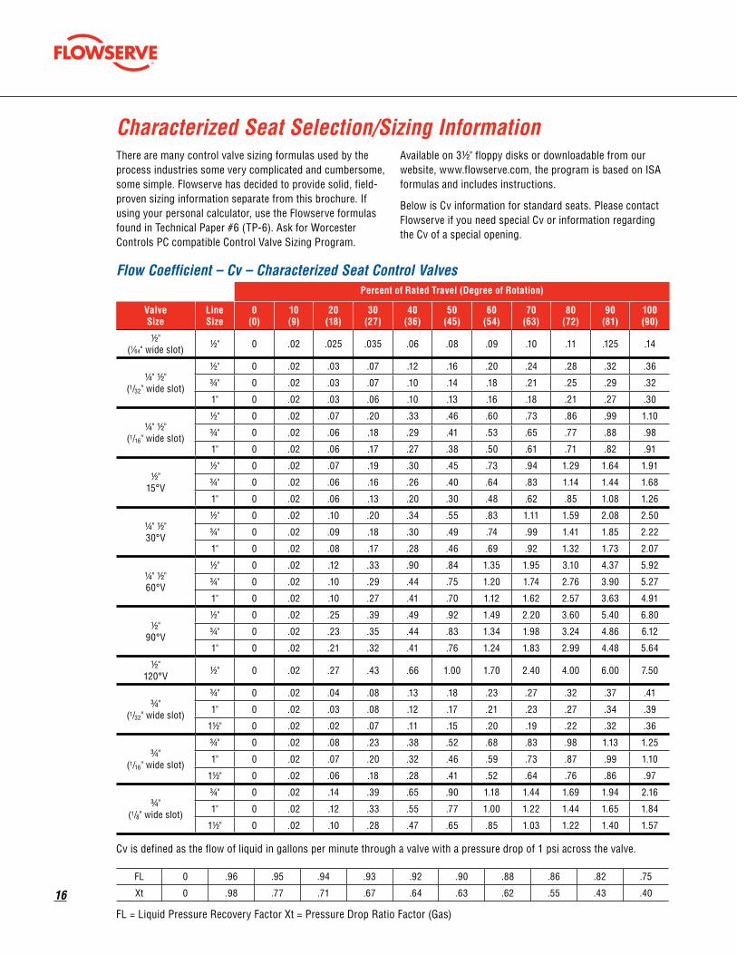
There are many control valve sizing formulas used by the process industries some very complicated and cumbersome, some simple. Flowserve has decided to provide solid, field-proven sizing information separate from this brochure. If using your personal calculator, use the Flowserve formulas found in Technical Paper #6 (TP-6). Ask for Worcester Controls PC compatible Control Valve Sizing Program.
Available on 31/2" floppy disks or downloadable from our website, www.flowserve.com, the program is based on ISA formulas and includes instructions.
Below is Cv information for standard seats. Please contact Flowserve if you need special Cv or information regarding the Cv of a special opening.
Characterized Seat Selection/Sizing Information
Percent of Rated Travel (Degree of Rotation)
Valve Size
Line Size
0 (0)
10 (9)
20 (18)
30 (27)
40 (36)
50 (45)
60 (54)
70 (63)
80 (72)
90 (81)
100 (90)
1/2" (1⁄64" wide slot) 1/2" 0 .02 .025 .035 .06 .08 .09 .10 .11 .125 .14
1/4" 1/2" (1/32" wide slot)
1/2" 0 .02 .03 .07 .12 .16 .20 .24 .28 .32 .36
3/4" 0 .02 .03 .07 .10 .14 .18 .21 .25 .29 .32
1" 0 .02 .03 .06 .10 .13 .16 .18 .21 .27 .30
1/4" 1/2" (1/16" wide slot)
1/2" 0 .02 .07 .20 .33 .46 .60 .73 .86 .99 1.10
3/4" 0 .02 .06 .18 .29 .41 .53 .65 .77 .88 .98
1" 0 .02 .06 .17 .27 .38 .50 .61 .71 .82 .91
1/2" 15°V
1/2" 0 .02 .07 .19 .30 .45 .73 .94 1.29 1.64 1.91
3/4" 0 .02 .06 .16 .26 .40 .64 .83 1.14 1.44 1.68
1" 0 .02 .06 .13 .20 .30 .48 .62 .85 1.08 1.26
1/4" 1/2" 30°V
1/2" 0 .02 .10 .20 .34 .55 .83 1.11 1.59 2.08 2.50
3/4" 0 .02 .09 .18 .30 .49 .74 .99 1.41 1.85 2.22
1" 0 .02 .08 .17 .28 .46 .69 .92 1.32 1.73 2.07
1/4" 1/2" 60°V
1/2" 0 .02 .12 .33 .90 .84 1.35 1.95 3.10 4.37 5.92
3/4" 0 .02 .10 .29 .44 .75 1.20 1.74 2.76 3.90 5.27
1" 0 .02 .10 .27 .41 .70 1.12 1.62 2.57 3.63 4.91
1/2" 90°V
1/2" 0 .02 .25 .39 .49 .92 1.49 2.20 3.60 5.40 6.80
3/4" 0 .02 .23 .35 .44 .83 1.34 1.98 3.24 4.86 6.12
1" 0 .02 .21 .32 .41 .76 1.24 1.83 2.99 4.48 5.64
1/2" 120°V 1/2" 0 .02 .27 .43 .66 1.00 1.70 2.40 4.00 6.00 7.50
3/4" (1/32" wide slot)
3/4" 0 .02 .04 .08 .13 .18 .23 .27 .32 .37 .41
1" 0 .02 .03 .08 .12 .17 .21 .23 .27 .34 .39
11/2" 0 .02 .02 .07 .11 .15 .20 .19 .22 .32 .36
3/4" (1/16" wide slot)
3/4" 0 .02 .08 .23 .38 .52 .68 .83 .98 1.13 1.25
1" 0 .02 .07 .20 .32 .46 .59 .73 .87 .99 1.10
11/2" 0 .02 .06 .18 .28 .41 .52 .64 .76 .86 .97
3/4" (1/8" wide slot)
3/4" 0 .02 .14 .39 .65 .90 1.18 1.44 1.69 1.94 2.16
1" 0 .02 .12 .33 .55 .77 1.00 1.22 1.44 1.65 1.84
11/2" 0 .02 .10 .28 .47 .65 .85 1.03 1.22 1.40 1.57
Flow Coefficient – Cv – Characterized Seat Control Valves
Cv is defined as the flow of liquid in gallons per minute through a valve with a pressure drop of 1 psi across the valve.
FL 0 .96 .95 .94 .93 .92 .90 .88 .86 .82 .75
Xt 0 .98 .77 .71 .67 .64 .63 .62 .55 .43 .40
FL = Liquid Pressure Recovery Factor Xt = Pressure Drop Ratio Factor (Gas)

flowserve.com
1�
Percent of Rated Travel (Degree of Rotation)
Valve Size
Line Size
0 (0)
10 (9)
20 (18)
30 (27)
40 (36)
50 (45)
60 (54)
70 (63)
80 (72)
90 (81)
100 (90)
3/4" 15°V
3/4" 0 .02 .08 .20 .28 .44 .71 .86 1.20 1.52 1.81
1" 0 .02 .07 .18 .27 .43 .70 .85 1.18 1.49 1.76
11/4" 0 .02 .06 .16 .23 .37 .60 .74 1.00 1.29 1.52
3/4" 30°V
3/4" 0 .02 .11 .24 .41 .67 1.00 1.39 1.94 2.55 3.04
1" 0 .02 .09 .21 .35 .59 .88 1.23 1.69 2.24 2.66
11/2" 0 .02 .08 .19 .31 .51 .78 1.08 1.47 1.96 2.33
3/4" 60°V
3/4" 0 .02 .13 .36 .55 .97 1.55 2.25 3.56 5.01 6.74
1" 0 .02 .13 .34 .51 .91 1.44 2.10 3.32 4.66 6.28
11/2" 0 .02 .13 .31 .48 .84 1.35 1.95 3.09 4.34 5.85
3/4" 90°V
3/4" 0 .02 .38 .60 .75 1.42 2.29 3.38 5.53 8.31 10.46
1" 0 .02 .33 .53 .66 1.25 2.02 2.97 4.87 7.31 9.20
11/4" 0 .02 .32 .50 .63 1.19 1.92 2.84 4.65 6.98 8.79
1" (1/32 wide slot)
1" 0 .02 .06 .14 .22 .29 .37 .45 .53 .60 .68
11/2" 0 .02 .06 .13 .19 .26 .33 .40 .47 .54 .61
2" 0 .02 .05 .12 .18 .24 .31 .33 .39 .50 .57
1" (1/16 wide slot)
1" 0 .02 .13 .38 .63 .87 1.14 1.39 1.63 1.88 2.09
11/2" 0 .02 .11 .34 .55 .78 1.01 1.23 1.46 1.67 1.86
2" 0 .02 .11 .32 .51 .72 .95 1.16 1.35 1.56 1.73
1" (1/8 wide slot)
1" 0 .02 .23 .66 1.09 1.52 1.99 2.42 2.85 3.28 3.64
11/2" 0 .02 .20 .57 .95 1.32 1.73 2.10 2.48 2.85 3.17
2" 0 .02 .19 .54 .89 1.25 1.63 1.98 2.34 2.69 2.98
1" 15°V
1" 0 .02 .14 .42 .66 1.04 1.70 2.13 2.87 3.68 4.32
11/4" 0 .02 .12 .37 .57 .90 1.48 1.85 2.50 3.20 3.76
11/2" 0 .02 .11 .33 .52 .82 1.34 1.68 2.27 2.91 3.41
1" 30°V
1" 0 .02 .21 .56 .96 1.58 2.39 3.43 4.62 6.15 7.26
11/2" 0 .02 .16 .44 .75 1.23 1.86 2.68 3.60 4.80 5.66
2" 0 .02 .15 .40 .69 1.14 1.72 2.47 3.33 4.43 5.23
1" 60°V
1" 0 .02 .30 .78 1.24 2.27 3.59 5.28 8.29 11.60 15.50
11/2" 0 .02 .23 .61 .97 1.77 2.80 4.12 6.47 9.05 12.10
2" 0 .02 .22 .56 .89 1.63 2.58 3.80 5.97 8.35 11.20
1" 90°V
1" 0 .02 .48 1.23 2.30 3.50 5.40 7.70 10.80 12.10 19.70
11/4" 0 .02 .42 1.08 2.02 3.08 4.75 6.78 9.50 10.65 17.34
11/2" 0 .02 .38 .98 1.84 2.80 4.32 6.16 8.64 9.68 15.76
1" 120°V 1" 0 .02 1.10 1.80 2.60 4.00 6.50 9.80 15.80 24.20 29.80
Flow Coefficient – Cv – Characterized Seat Control Valves
Cv is defined as the flow of liquid in gallons per minute through a valve with a pressure drop of 1 psi across the valve.
FL 0 .96 .95 .94 .93 .92 .90 .88 .86 .82 .75
Xt 0 .98 .77 .71 .67 .64 .63 .62 .55 .43 .40
FL = Liquid Pressure Recovery Factor Xt = Pressure Drop Ratio Factor (Gas)

1�
Percent of Rated Travel (Degree of Rotation)
Valve Size
Line Size
0 (0)
10 (9)
20 (18)
30 (27)
40 (36)
50 (45)
60 (54)
70 (63)
80 (72)
90 (81)
100 (90)
11/2" (1/32 wide slot)
11/2" 0 .02 .10 .22 .34 .46 .58 .70 .82 .94 1.06
2" 0 .02 .09 .20 .31 .42 .54 .59 .69 .88 1.00
21/2" 0 .02 .08 .19 .29 .39 .50 .49 .58 .81 .93
11/2" (1/16 wide slot)
11/2" 0 .02 .21 .59 .98 1.36 1.78 2.16 2.55 2.93 3.26
2" 0 .02 .21 .56 .91 1.26 1.68 2.03 2.35 2.73 3.03
21/2" 0 .02 .20 .53 .85 1.17 1.58 1.90 2.17 2.55 2.82
11/2" (1/8 wide slot)
11/2" 0 .02 .36 1.05 1.73 2.41 3.15 3.83 4.51 5.20 5.77
2" 0 .02 .31 .88 1.47 2.04 2.68 3.25 3.84 4.41 4.91
21/2" 0 .02 .25 .74 1.26 1.73 2.28 2.75 3.27 3.75 4.18
11/2" 15°V
11/2" 0 .02 .23 .71 1.42 2.35 3.44 5.04 6.92 9.24 11.06
2" 0 .02 .19 .59 1.18 1.95 2.86 4.18 5.74 7.67 9.18
21/2" 0 .02 .17 .53 1.05 1.74 2.55 3.73 5.12 6.84 8.18
11/2" 30°V
11/2" 0 .02 .41 1.16 2.12 3.51 5.22 7.56 10.28 13.71 16.28
2" 0 .02 .38 1.05 2.00 3.14 4.83 6.80 9.51 12.66 15.04
21/2" 0 .02 .36 .96 1.80 2.80 4.47 6.11 8.80 11.68 13.90
11/2" 60°V
11/2" 0 .02 .57 1.74 2.99 5.59 9.07 13.16 19.80 28.42 37.51
2" 0 .02 .53 1.60 2.76 5.15 8.36 12.13 18.27 26.23 34.74
21/2" 0 .02 .48 1.47 2.54 4.74 7.70 11.19 16.87 24.21 32.16
11/2" 90°V
11/2" 0 .02 .66 2.48 4.59 8.74 14.55 20.63 30.07 44.25 57.75
2" 0 .02 .55 2.08 3.86 7.34 12.22 17.33 25.26 37.17 48.51
21/2" 0 .02 .51 1.84 3.40 6.47 10.77 15.27 22.25 32.75 42.74
2" 15°V
2" 0 .02 .33 1.02 2.03 3.36 4.92 7.20 9.88 13.20 15.80
21/2" 0 .02 .29 .91 1.81 2.99 4.38 6.41 8.79 11.75 14.06
3" 0 .02 .26 .82 1.62 2.69 3.94 5.76 7.51 10.56 12.64
2" 30°V
2" 0 .02 .55 1.72 3.41 5.65 8.26 12.10 16.60 22.20 26.50
3" 0 .02 .45 1.41 2.80 4.63 6.77 9.92 13.60 18.20 21.70
4" 0 .02 .41 1.27 2.52 4.18 6.11 8.95 12.30 16.40 19.60
2" 60°V
2" 0 .02 .70 2.64 4.90 9.32 15.50 22.20 32.10 47.20 61.60
3" 0 .02 .57 2.16 4.02 7.64 12.70 18.20 26.30 38.70 50.50
4" 0 .02 .52 1.95 3.63 6.90 11.50 16.40 23.80 34.90 45.60
2" 90°V
2" 0 .02 .88 3.30 6.13 11.65 19.40 27.50 40.10 59.00 77.00
21/2" 0 .02 .79 2.94 5.46 10.39 17.27 24.48 35.69 52.51 68.53
3" 0 .02 .73 2.74 5.09 10.37 17.27 22.83 33.28 48.97 63.91
2" 120°V 2" 0 .02 1.86 5.25 10.30 15.80 25.30 37.10 59.50 91.80 110.80
Cv is defined as the flow of liquid in gallons per minute through a valve with a pressure drop of 1 psi across the valve.
FL 0 .96 .95 .94 .93 .92 .90 .88 .86 .82 .75
Xt 0 .98 .77 .71 .67 .64 .63 .62 .55 .43 .40
FL = Liquid Pressure Recovery Factor Xt = Pressure Drop Ratio Factor (Gas)
Flow Coefficient – Cv – Characterized Seat Control Valves

flowserve.com
19
Percent of Rated Travel (Degree of Rotation)
Valve Size
Line Size
0 (0)
10 (9)
20 (18)
30 (27)
40 (36)
50 (45)
60 (54)
70 (63)
80 (72)
90 (81)
100 (90)
3" 15°V
3" 0 .02 .56 1.90 4.20 6.10 8.50 12.30 16.90 20.20 24.40
4" 0 .02 .39 1.33 2.94 4.27 5.95 8.61 11.83 14.14 17.08
6" 0 .02 .31 1.05 2.31 3.36 4.68 6.77 9.30 11.11 13.42
3" 30°V
3" 0 .02 .75 2.68 6.00 10.20 16.90 24.50 33.90 44.80 54.20
4" 0 .02 .54 1.93 4.32 7.34 12.20 17.60 24.40 32.30 39.00
6" 0 .02 .41 1.47 3.30 5.61 9.30 13.50 18.60 24.60 29.80
3" 60°V
3" 0 .02 .95 4.25 10.10 18.60 29.40 46.30 67.20 94.40 124.60
4" 0 .02 .68 3.06 7.27 13.40 21.20 33.30 48.40 68.00 89.70
6" 0 .02 .52 2.34 5.56 10.20 16.20 25.50 37.00 51.90 68.50
3" 90°V
3" 0 .02 1.22 5.50 14.00 26.00 44.00 67.00 102.00 151.00 230.00
4" 0 .02 .85 3.85 9.80 18.20 30.80 46.90 71.40 105.70 161.00
6" 0 .02 .67 3.03 7.70 14.30 24.20 36.85 56.10 83.05 126.50
3" 120°V 3" 0 .02 2.40 11.50 26.00 39.70 65.00 96.00 157.00 235.00 293.00
4" 15°V
4" 0 .02 4.20 10.00 13.90 17.90 21.70 27.90 34.00 41.20 45.00
6" 0 .02 2.77 6.66 9.17 11.81 14.32 18.41 22.44 27.19 29.70
8" 0 .02 2.31 5.50 7.65 9.85 11.94 15.35 18.70 22.66 24.75
4" 30°V
4" 0 .02 .80 3.59 8.50 16.10 26.80 40.20 56.60 72.50 89.80
6" 0 .02 .52 2.33 5.53 10.50 17.40 26.10 36.80 47.10 58.40
8" 0 .02 .44 1.97 4.68 8.86 14.70 22.10 31.10 39.90 49.40
4" 60°V
4" 0 .02 .90 5.69 15.40 28.80 48.60 73.40 107.00 150.70 200.00
6" 0 .02 .59 3.70 10.00 18.70 31.60 47.70 69.60 98.00 130.00
8" 0 .02 .50 3.13 8.47 15.80 26.70 40.40 58.90 82.90 110.00
4" 90°V
4" 0 .02 2.00 9.00 23.00 42.00 72.00 110.00 167.00 250.00 380.00
6" 0 .02 1.28 5.76 14.72 26.88 46.08 70.40 106.88 160.00 243.20
8" 0 .02 1.10 4.95 12.65 23.10 39.60 60.50 91.85 137.50 209.00
4" 120°V
4" 0 .02 3.00 14.00 35.00 64.00 110.00 168.00 255.00 383.00 580.00
6" 0 .02 2.00 9.00 22.00 40.00 69.00 106.00 161.00 240.00 365.00
Cv is defined as the flow of liquid in gallons per minute through a valve with a pressure drop of 1 psi across the valve.
FL 0 .96 .95 .94 .93 .92 .90 .88 .86 .82 .75
Xt 0 .98 .77 .71 .67 .64 .63 .62 .55 .43 .40
FL = Liquid Pressure Recovery Factor Xt = Pressure Drop Ratio Factor (Gas)
Flow Coefficient – Cv – Characterized Seat Control ValvesPercent of Rated Travel (Degree of Rotation)

�0
Percent of Rated Travel (Degree of Rotation)
Size Type 0 (0)
10 (9)
20 (18)
30 (27)
40 (36)
50 (45)
60 (54)
70 (63)
80 (72)
90 (81)
100 (90)
1/4 or 1/2
1/64 slot 0.00 0.01 0.02 0.02 0.04 0.06 0.06 0.07 0.08 0.09 0.10
1/32 slot 0.00 0.01 0.02 0.05 0.08 0.11 0.14 0.17 0.20 0.23 0.25
1/16 slot 0.00 0.01 0.05 0.14 0.23 0.33 0.42 0.52 0.61 0.70 0.78
15° V 0.00 0.01 0.05 0.13 0.21 0.32 0.52 0.66 0.91 1.16 1.35
30° V 0.00 0.01 0.07 0.14 0.24 0.39 0.59 0.78 1.12 1.47 1.77
60° V 0.00 0.01 0.08 0.23 0.64 0.59 0.95 1.38 2.19 3.09 4.19
90° V 0.00 0.01 0.18 0.28 0.35 0.65 1.05 1.56 2.55 3.82 4.81
120° V 0.00 0.01 0.19 0.30 0.47 0.71 1.20 1.70 2.83 4.24 5.30
3/4
1/32 slot 0.00 0.01 0.03 0.06 0.09 0.13 0.16 0.19 0.23 0.26 0.29
1/16 slot 0.00 0.01 0.06 0.16 0.27 0.37 0.48 0.59 0.69 0.80 0.88
1/8 slot 0.00 0.01 0.10 0.28 0.46 0.64 0.83 1.02 1.19 1.37 1.53
15° V 0.00 0.01 0.06 0.14 0.20 0.31 0.50 0.61 0.85 1.07 1.28
30° V 0.00 0.01 0.08 0.17 0.29 0.47 0.71 0.98 1.37 1.80 2.15
60° V 0.00 0.01 0.09 0.25 0.39 0.69 1.10 1.59 2.52 3.54 4.77
90° V 0.00 0.01 0.27 0.42 0.53 1.00 1.62 2.39 3.91 5.88 7.40
120° V 0.00 0.01 0.30 0.47 0.58 1.10 1.78 2.63 4.30 6.46 8.13
1
1/32 slot 0.00 0.01 0.04 0.10 0.16 0.21 0.26 0.32 0.37 0.42 0.48
1/16 slot 0.00 0.01 0.09 0.27 0.45 0.62 0.81 0.98 1.15 1.33 1.48
1/8 slot 0.00 0.01 0.16 0.47 0.77 1.07 1.41 1.71 2.01 2.32 2.57
15° V 0.00 0.01 0.10 0.30 0.47 0.74 1.20 1.51 2.03 2.60 3.05
30° V 0.00 0.01 0.15 0.40 0.68 1.12 1.69 2.43 3.27 4.35 5.13
60° V 0.00 0.01 0.21 0.55 0.88 1.60 2.54 3.73 5.86 8.20 10.96
90° V 0.00 0.01 0.34 0.87 1.63 2.47 3.82 5.44 7.64 8.55 13.93
120° V 0.00 0.01 0.78 1.27 1.84 2.83 4.60 6.93 11.17 17.11 21.07
1 1/2
1/32 slot 0.00 0.01 0.07 0.16 0.24 0.33 0.41 0.49 0.58 0.66 0.75
1/16 slot 0.00 0.01 0.15 0.42 0.69 0.96 1.26 1.53 1.80 2.07 2.30
1/8 slot 0.00 0.01 0.25 0.74 1.22 1.70 2.23 2.71 3.19 3.68 4.08
15° V 0.00 0.01 0.16 0.50 1.00 1.66 2.43 3.56 4.89 6.53 7.82
30° V 0.00 0.01 0.29 0.82 1.50 2.48 3.69 5.34 7.27 9.69 11.51
60° V 0.00 0.01 0.40 1.23 2.11 3.95 6.41 11.43 14.00 20.09 26.52
90° V 0.00 0.01 0.47 1.75 3.25 6.18 10.29 14.59 21.26 31.28 40.83
120° V 0.00 0.01 0.71 2.65 4.91 9.35 15.56 22.06 32.16 47.32 61.76
2
15° V 0.00 0.01 0.23 0.72 1.44 2.38 3.48 5.09 6.99 9.33 11.17
30° V 0.00 0.01 0.39 1.22 2.41 3.99 5.84 8.55 11.74 15.70 18.74
60° V 0.00 0.01 0.49 1.87 3.46 6.59 10.96 15.70 22.69 33.37 43.55
90° V 0.00 0.01 0.62 2.33 4.33 8.24 13.72 19.44 28.35 41.71 54.44
120° V 0.00 0.01 1.32 3.71 7.28 11.17 17.89 26.23 42.07 64.90 78.34
3
15° V 0.00 0.01 0.40 1.34 2.97 4.31 6.01 8.70 11.95 14.28 17.25
30° V 0.00 0.01 0.53 1.89 4.24 7.21 11.95 17.32 23.97 31.67 38.32
60° V 0.00 0.01 0.67 3.00 7.14 13.15 20.79 32.73 47.51 66.74 88.09
90° V 0.00 0.01 0.86 3.89 9.90 18.38 31.11 47.37 72.11 106.76 162.61
120° V 0.00 0.01 1.70 8.13 18.38 28.07 45.25 67.87 111.00 166.15 207.15
4
15° V 0.00 0.01 2.97 7.07 9.83 12.66 15.34 19.73 24.04 29.13 31.82
30° V 0.00 0.01 0.57 2.54 6.01 11.38 18.95 28.42 40.02 51.26 63.49
60° V 0.00 0.01 0.64 4.02 10.89 20.36 34.36 51.89 75.65 106.54 141.40
90° V 0.00 0.01 1.41 6.36 16.26 29.69 50.90 77.77 118.07 176.75 268.66
120° V 0.00 0.01 2.12 9.90 24.75 45.25 77.77 118.78 180.29 270.78 410.06
Cv is defined as the flow of liquid in gallons per minute through a valve with a pressure drop of 1 psi across the valve.
Fl 1 0.99 0.99 0.98 0.98 0.98 0.97 0.96 0.96 0.95 0.925
Xt 1 0.99 0.93 0.91 0.9 0.89 0.88 0.88 0.86 0.82 0.81
FL = Liquid Pressure Recovery Factor Xt = Pressure Drop Ratio Factor (Gas)
Flow Coefficient – Cv – Vee-Twin Valves

flowserve.com
�1
Standard Reduced Port Ball ValvesThe valve torque curve (page 21) shows the torque require-ments of 1/4" through 10" Worcester ball valves as a function of differential pressure across the valve when the ball is in the closed position.
NOTE: These curves have been developed for applications involving CLEAN media.
Based on valve size, seat material and differential pressure across the valve (in the closed position), the amount of torque required by the ball valve can be determined by the following procedures:
1. Find the valve torque from the torque curves on page 21 by using the differential pressure across the valve in the closed position. To do this, locate the differential pressure on the horizontal axis of the chart and move up until you arrive at the appropriate valve size, transfer the intersecting point across to the vertical axis of the graph, and read the required torque.
2. Multiply this torque value by one or more of the applica-tion factor multipliers shown below. Maximum cumulative multiplier = 2.
Application factor Multiplier A. Service
On-off ..................................................................................1.0 Emergency shutdown cycled less than once per month ...................................................2.0 Throttling control with positioner .......................................1.2 Applications with less than two cycles/day ........................1.2 Applications below -20°F ..................................................1.25
B. Media
Saturated steam ..................................................................1.2 Clean saturated steam ........................................................1.0 Liquid, clean (particle free) .................................................1.0 Liquid, dirty (slurry), raw water ..........................................1.8 Gas, clean and wet ..............................................................1.2 Gas, clean and dry (super heated steam) ...........................1.0 Gas, dirty (natural gas) .......................................................1.5 Chlorine ...............................................................................1.5
Series 94 ValvesSeries 94 valves with TFE, reinforced TFE, Polyfill and Metal “A” seats with TFE stem seals use the same torque values as standard valves shown on page 21. Series 94 valves with UHMWPE, High-per Fill and Metal “G” seats use Grafoil stem seals, which have higher operating torques. See the note at the bottom of the curves on page 21 for the additional torque required with Grafoil packing.
Actuator SelectionOnce the torque requirements of the valve have been determined, the actuator can be properly sized.
Pneumatic Actuators
Before sizing the actuator for the valve, there are a few pieces of information which must be determined, including the style of actuator (Series 34 or 39), the minimum air supply pressure available, and the type of operation (double-acting or spring-return) that the actuator is to perform. If the actuator is to be spring-return, the failure mode (fail closed or fail open) must also be determined.
1. Double-acting operation — Select the actuator whose torque output, at the minimum air supply pressure, exceeds the calculated torque requirements of the valve. Actuator torque output charts are shown on pages 22 and 23.
2. Spring-return operation, fail closed — Select the actuator whose torque output, at the minimum air supply pressure, at the end of spring stroke, exceeds the torque required to close the valve.
3. Spring-return operation, fail open — Select the actuator whose torque output, at the minimum air supply pressure, at the end of air stroke, exceeds the torque required to close the valve.
Electric Actuators
There are a few terms associated with electric actuators that require definition. Actuator startup torque is the amount of torque initially produced by an actuator when starting from rest. Use startup torque when selecting an electric actuator for a ball valve. Actuator stall torque is the amount of torque produced by the actuator just prior to the point where the motor stalls.
Select the actuator whose startup torque output exceeds the breakaway torque requirements of the valve. Electric actuator torque outputs are shown on page 22.
For valves other than ball valves, actuators must be selected such that startup torque exceeds the maximum torque rating of the valve.
Before making a final selection, make sure that the electric actuator selected is available in the required voltage. Not all electric actuators are available in all voltages.
Actuator Sizing – Determination of Valve Torque

��
Actuator Output Charts (in-lb)
Actuator Size
Operating Pressure (psi)
30 40 50 60 70 80 90 100 110 120
5 33.6 48.6 59.7 73.5 86.3 97.4 106 126 137 148
10 80 125 160 200 245 270 310 350 385 425
15 155 240 300 370 460 510 580 650 725 790
20 285 435 545 680 840 935 1070 1200 1330 1460
25 590 785 980 1180 1375 1570 1770 1965 2160 2355
30 790 1200 1500 1860 2305 2580 2935 3290 3645 4000
33 1600 2230 2280 3520 4160 4800 5430 6070 6720 7330
35 2220 2975 3900 4800 5600 6400 7200 8000 8800 9600
40 Rev. 3 3510 4710 6170 7390 8710 10040 11400 12700 13970 15270
42 Rev. 3 6500 8700 10900 13090 15330 17530 19720 21920 24120 26310
45 Rev. 1 9000 12700 16100 19500 22700 26000 29400 32600 36000 39500
50 Rev. 1 13145 19000 24000 29000 34000 40000 45000 50000 55000 60000
Series �9 – Double-acting
Pressure Torque Data for CPT Control ValvesMetal “A” and Metal “G” Characterized Seats with Metal “A” (A), Metal “G” (G), High-per Fill (X), fluoropolymer (T), Polyfill (P) Round Seats or Vee-Twin Configuration
Valve size/seat 0 100 200 300 400 500
1/2" T,P 70 72 74 76 78 80
1/2" X,G,A 95 104 113 122 131 140
3/4" T,P 80 86 92 98 104 110
3/4" X,G,A 120 134 148 162 176 190
1" T,P 175 180 185 190 195 200
1" X,G,A 220 227 234 241 248 255
1 1/2" T,P 280 288 296 304 312 320
1 1/2" X,G,A 360 364 368 372 376 380
2" T,P 440 458 476 494 512 530
2" X,G,A 540 556 572 588 604 620
3" All seats 1200 1300 1400 1500 1600 1700
4" All seats 1800 2220 2640 3060 3480 3900
1/2" Vee-Twin 110 114 118 122 126 130
3/4" Vee-Twin 140 145 150 155 160 165
1" Vee-Twin 260 264 268 272 276 280
1 1/2" Vee-Twin 425 430 435 440 445 450
2" Vee-Twin 640 658 676 694 712 730
3" Vee-Twin 1400 1500 1600 1700 1800 1900
4" Vee-Twin 2300 2520 2740 2960 3180 3400
*For Series CPT 94 control valves with Grafoil stem seals, add the following torque values to the curve values above: 1/2" – 3/4", 90 in-lb; 11/2" – 2", 150 in-lb; 3" – 4", 200 in-lb.

flowserve.com
��
Actuator Size
Startup Torque (in-lb)
10 120
12 180
15 260
20 480
22 720
23 950
25 1440
30 2400
Series �� – Electric
Series �9 – Spring-Return
Operating Pressure
30 psi 40 psi 50 psi 60 psi 70 psi 80 psi
Size Stroke Start End Start End Start End Start End Start End Start End
No. of Springs 2 2 2 4
0539Air 28 15 35 30 50 40 45 30
Spring 41 31 41 31 41 31 53 40
No. of Springs 2 4 6 8 8 10
1039Air 70 40 85 60 105 60 125 70 170 120 175 95
Spring 58 35 60 35 95 55 25 75 125 75 160 95
1539Air 140 80 130 85 200 125 240 150 200 165 325 190
Spring 100 60 105 74 105 105 220 145 220 145 200 105
2039Air 220 150 300 240 340 235 415 280 575 440 600 360
Spring 140 96 190 126 300 195 400 265 400 265 505 335
2539Air 220 110 560 400 600 350 730 420 925 655 980 550
Spring 240 170 345 210 540 330 720 450 720 450 915 575
3039Air 324 180 840 610 965 600 1130 690 1575 1145 1650 920
Spring 456 264 560 340 870 535 1160 730 1160 730 1470 920
3339Air 1550 1160 1810 1200 2060 1220 2700 1860 2950 1900
Spring 1070 680 1680 1070 2300 1460 2300 1460 2900 1850
3539Air 1560 1260 2100 1470 2360 1450 2850 1730 3570 2615 3850 2210
Spring 900 720 1330 850 2070 1330 2770 1815 2770 1815 3500 2300
4039Air 3410 2300 3980 2350 4470 2390 5620 3450 6150 3500
Spring 2490 1500 3730 2240 4970 2980 4970 2980 6210 3740
4239Air 6550 4520 7280 4140 7960 3390 10510 6190 10920 5590
Spring 4560 2390 6900 3800 9290 4870 9290 4890 11720 6370
No. of Springs 12 16 18 22 24
4539Air 8700 4000 10600 4300 13200 5900 14900 6100 17600 8000
Spring 8300 4000 11800 5500 15600 6300 16600 7800 18000 8400
5039Air 12500 6000 15500 6000 19500 8500 21800 8000 26500 11500
Spring 13000 6500 18000 8500 20500 9500 26000 12200 13500
Actuator Output Charts (in-lb)

�4
Dimensions for CPT 44 Control ValvesD
A
G
C B
Port
F
H
J
K M I.D. O.D.
L N
Socket Weld SW
O.D. Tube End SWO
Tube End TE K, L, OR M
(Copper Tube)
Butt Weld BW SCH. 5, 10 (Stainless Steel) SCH. 4, 80 (Carbon Steel)
*The inside configuration of O.D. tube pipe ends varies by size and material. *For XBO and TC ends, call Flowserve.
Carbon Steel
Dimensions in inches (mm)

flowserve.com
��
Dimensions for 94 Three-Piece
Valve Size A B C D E F G H K M N Port
Weight lb (kg)
1/4" 2.54 (64.52)
.813 (20.65)
2.67 (67.82)
4.40 (111.76)
.70 (17.78)
4.75 (120.65)
8.00 (203.20)
1.75 (44.45)
.296 (7.52)
.44 (11.18)
.555 (14.10)
.44 (11.18)
2 (.91)
3/8" 2.54 (64.52)
.813 (20.65)
2.67 (67.82)
4.40 (111.76)
.70 (17.78)
4.75 (120.65)
8.00 (203.20)
1.75 (44.45)
.296 (7.52)
.44 (11.18)
.690 (17.53)
.44 (11.18)
2 (.91)
1/2" 2.54 (64.52)
.813 (20.65)
2.67 (67.82)
4.40 (111.76)
.70 (17.78)
4.75 (120.65)
8.00 (203.20)
1.75 (44.45)
.296 (7.52)
.44 (11.18)
.855 (21.72)
.44 (11.18)
3 (1.4)
3/4" 2.76 (70.10)
.969 (24.61)
2.76 (70.10)
4.49 (114.05)
.70 (17.78)
4.84 (122.94)
8.00 (203.20)
2.00 (50.80)
.296 (7.52)
.56 (14.22)
1.065 (27.05)
.56 (14.22)
4 (1.8)
1" 3.66 (92.96)
1.250 (31.75)
3.18 (80.77)
4.91 (124.71)
.70 (17.78)
5.26 (133.60)
8.00 (203.20)
2.38 (60.45)
.343 (8.71)
.72 (18.29)
1.330 (33.78)
.81 (20.57)
5 (23)
11/4" 4.16 (105.66)
1.625 (41.27)
3.37 (85.60)
5.10 (129.54)
.70 (17.78)
5.45 (138.43)
8.00 (203.20)
2.70 (68.58)
.343 (8.71)
.72 (18.29)
1.675 (42.55)
1.00 (25.40)
10 (4.5)
11/2" 4.50 (114.36)
1.906 (48.41)
3.82 (97.03)
5.66 (143.76)
.75 (19.05)
6.14 (155.96)
10.00 (254.00)
3.16 (80.26)
.500 (12.70)
.72 (18.29)
1.915 (48.64)
1.25 (31.75)
11 (5.0)
2" 4.94 (125.48)
2.213 (56.21)
4.01 (101.85)
5.85 (148.59)
.75 (19.05)
6.33 (160.78)
10.00 (254.00)
3.56 (90.42)
.500 (12.70)
.84 (21.34)
2.406 (61.11)
1.50 (38.1)
13 (5.9)
¼"–�" 94 Three-PieceDimensions in inches (mm)
K
H
C
F
G
N
M
Port
D
B
A

�6
Dimensions for 1¼"–�" CPT 44 Series Valves Mounted to �� and �0 �9 Series Actuators with L9�W Pulsair III Positioner
Dimensions
Actuator
2539 3039
Valve Size A B C D
Act. Size E F G H J K L M N
Valve Size P
11/4" 4.16 2.70 4.46 5.00 2539 5.34 5.31 10.62 4.07 3.00 7.91 4.00 3.23 8.29 11/4" 11.42 12.24
11/2" 4.50 3.16 4.73 5.00 3039 6.10 6.39 12.77 4.48 3.00 7.91 4.00 3.23 8.70 11/2" 11.69 12.51
2" 4.94 3.56 4.92 5.00 2" 11.88 12.70
Actuator shown in the closed position with pistons together. Dimensions for high temperature actuators are the same as the equivalent size standard temperature actuators.
Dimensions in inches (mm)

flowserve.com
��
Dimensions for �9 Pneumatic Actuator with Pulsair® and Pulsair III Positioner
Actuator Size D.A. or S.R. C E
10 3.05 (77.5)
1.52 (38.6)
15 3.84 (97.5)
1.86 (47.2)
20 4.62 (117.4)
2.30 (58.4)
25 5.31 (134.9)
2.67 (67.8)
30 6.39 (162.3)
3.05 (77.5)
Valve Size
Face-to-face Center-to-face 39 Pneumatic Actuator Direct-acting or Spring-return
with Pulsair III Positioner
A 51 (150#)
A1 52 (300#)
A2 51 (150#)
A3 52 (300#) Size
B - S 51/52, CPT 51/52
B1 CPT 94
1/2" 4.25 (108.0)
5.50 (139.7)
1.81 (45.97)
2.31 (58.67) 10 11.31
(287)14.06 (357)
3/4" 4.62 (117.4)
6.0 (152.4)
1.94 (49.28)
2.44 (61.98)
10 11.40 (290)
14.15 (359)
15 12.12 (308)
14.87 (378)
1" 5.00 (127.0)
6.50 (165.1)
2.25 (57.15)
2.75 (69.85)
15 12.36 (314)
15.29 (388)
20 13.19 (335)
16.12 (409)
11/2" 6.50 (165.0)
7.50 (190.5)
2.45 (62.23)
2.95 (74.93)
20 14.15 (359)
16.80 (427)
25 15.91 (404)
18.59 (472)
2" 7.00 (178.0)
8.50 (215.9)
2.67 (67.82)
3.17 (80.52)
20 14.34 (364)
16.99 (432)
25 16.10 (409)
18.78 (477)
30 16.92 (430)
19.60 (498)
1/2"–�" CPT �1/�� and 1/2"–�" CPT 94 Flanged Control Valves 1/2"–�" S �1/�� Flanged Standard Seat Control Valves
B, B1
9.3"
4.0"
B, B1
E
8.9"
C
A, A1
A2, A3
A, A1
A2, A3
E
SERIES 39
SERIES L93
SERIES 39
SERIES L90
7.0"
39 Actuator with Pulsair III Positioner
Dimensions in inches (mm)
Dimensions in inches (mm)

��
Valve Size
Face-to-face 39 Pneumatic Actuator Direct-acting or Spring-return
with Pulsair III Positioner
A (150#)
A1 (300#)
A2 (150, 300#) Size
B 51/52
B CPT 51/52
B1 CPT 94
3" 8.00 (203.2)
11.12 (282.5)
3.62 (91.9)
25 18.21 (463)
18.21 (463)
19.13 (486)
30 19.26 (489)
19.26 (489)
19.95 (507)
33 21.42 (544)
21.42 (544)
22.55 (573)
35 21.52 (547)
21.52 (547)
22.65 (575)
4" 9.00 (228.6)
12.00 (304.8)
4.00 (101.6)
30 19.86 (504)
19.86 (504)
20.55 (522)
33 22.02 (559)
22.02 (559)
23.15 (588)
35 22.12 (562)
22.12 (562)
23.25 (591)
40 24.89 (632)
24.89 (632)
25.58 (650)
�" & 4" CPT �1/�� and �" and 4" CPT 94 Flanged Control Valves �"–�" �1/�� Flanged Standard Seat Control Valves
7.0"
E
B, B1
9.3"
4.0"
B, B1
E
8.9"
C
A, A1A2
A, A1A2
SERIES 39
SERIES L93
SERIES 39
SERIES L90
Actuator Size D.A. or S.R. C E
25 5.31 (134.9)
2.67 (67.8)
30 6.39 (162.3)
3.05 (77.5)
33 7.83 (119.0)
4.04 (102.5)
35 8.31 (211.1)
4.17 (105.9)
40 10.00 (254.0)
4.82 (122.4
42 12.12 (307.8)
5.57 (141.5)
45 11.43 (290.3)
6.60 (167.6)
Dimensions for �9 Pneumatic Actuator with Pulsair III Positioner
39 Actuator with Pulsair III Positioner
Dimensions in inches (mm)

flowserve.com
�9
Dimensions for Series CPT 1�1/�01/4 Wafer-Style Control Valves
Valve Size A B C D G H JPort
Diameter
Approx.Weight lb (kg)
3" 4.50 (114.3)
2.25 (57.2)
5.31 (134.9)
3.88 (98.6)
7.22 (183.4)
22.00 (558.8)
5.88 (149.4)
2.50 (63.5)
21 (9.5)
4" 5.81 (147.6)
2.90 (73.7)
6.81 (173.0)
4.48 (113.8)
7.84 (199.1)
22.00 (558.8)
7.50 (190.5)
3.25 (82.6)
34 (15.4)
Dimensions in inches (mm)

�0
Dimensions for Valve and �� Electric Actuator
Series 75 Electric Actuator†
Valve Size
A Face-to-face Center to face
SizeB B1
Three-piece (SW, BW1, BW4)
A 51 A1 52 A2 51 A3 52
(150#) (300#) (150#) (300#) S 44/51/52 & CPT 44/51/52 CPT 94
1/4", 1/2" 2.54 (64.5)
4.25 (108.0)
5.50 (139.7)
1.81 (45.97)
2.31 (58.67) 10 through 23 11.44
(291)14.19 (360)
3/4" 2.76 (70.1)
4.62 (117.4)
6.0 (152.4)
1.94 (49.28)
2.44 (61.98) 10 through 23 11.53
(293)14.28 (363)
1" 3.66 (93.0)
5.00 (127.0)
6.50 (165.1)
2.25 (57.15)
2.75 (69.85) 10 through 23 11.77
(299)14.70 (373)
11/4" (S 44 only)
4.16 (105.7) — — — — 10 through 23 11.96
(304) —
11/2" 4.50 (114.3)
6.50 (165.0)
7.50 (190.5)
2.45 (62.23)
2.95 (74.93) 10 through 23 12.73
(323)15.38 (391)
2"* 4.94 (125.5)
7.00 (178.0)
8.50 (215.9)
2.67 (67.82)
3.17 (80.52) 22, 23* 12.92
(328)15.56 (395)
Actuator Size C D E F
10 through 22 3.90 (99.1)
3.90 (99.1)
3.14 (79.8)
3.61 (91.7)
23 (and sizes 10 through 22 with “Z” enclosures)
4.23 (107.4)
4.23 (107.4)
3.48 (88.4)
3.97 (100.9)
Three-piece Valves
Flanged Valves
*A 2" CPT should not be sized with an electric actuator smaller than a 2275; a mechanical brake must also be ordered with this combination.
† B dimensions are for actuator sizes 10-22. Add 1.15" for 2375.
¼"–�" S44, CPT 44, CPT 94 Three-piece Control Valves 1/2"–�" S �1/��, CPT �1/��, CPT 94 Flanged Control Valvesinches (mm)

flowserve.com
�1
Series 75 Electric Actuator†
Valve SizeFace-to-face
Size BA A2
3"4.50 2.25
25 and 3021.64
(114.3) (57.2) (550)
4"5.81 2.90
25 and 3022.24
(147.6) (73.7) (565)
Series 75 Electric Actuator†
Valve Size
Face-to-face
Size
B B1
A A1 A2 CPT 51/52 CPT 94(150#) (300#) (150/300#)
3"8.00 11.12 3.62
25 and 3021.64 22.33
(203.2) (282.5) (91.9) (550) (567)
4"9.00 12.00 4.00
25 and 3022.24 22.93
(228.6) (304.8) (101.6) (565) (582)
Wafer Valves Flanged Valves
�"–4" CPT 44 Wafer Control Valves �"–4" 1�1/�01 Wafer Standard Seat Control Valves
�"–4" CPT �1/��/94 Flanged Valves �"–4" �1/�� Standard Seat Control Valves

flowserve.com
Flowserve CorporationFlow Control1978 Foreman DriveCookeville, Tennessee 38501Phone: 931 432 4021Fax: 931 432 3105www.flowserve.com
To find your local Flowserve representative, visit www.flowserve.com or call USA 1 �00 ��� 69�9
FCD WCENBR1001-02 Printed in USA.
Flowserve Corporation has established industry leadership in the design and manufacture of its products. When properly selected, this Flowserve product is designed to perform its intended function safely during its useful life. However, the purchaser or user of Flowserve products should be aware that Flowserve products might be used in numerous applications under a wide variety of industrial service conditions. Although Flowserve can (and often does) provide general guidelines, it cannot provide specific data and warnings for all possible applications. The purchaser/user must therefore assume the ultimate responsibility for the proper sizing and selection, installation, operation, and maintenance of Flowserve products. The purchaser/user should read and understand the Installation Operation Maintenance (IOM) instructions included with the product, and train its employees and contractors in the safe use of Flowserve products in connection with the specific application.
While the information and specifications contained in this literature are believed to be accurate, they are supplied for informative purposes only and should not be considered certified or as a guarantee of satisfactory results by reliance thereon. Nothing contained herein is to be construed as a warranty or guarantee, express or implied, regarding any matter with respect to this product. Because Flowserve is continually improving and upgrading its product design, the specifications, dimensions and information contained herein are subject to change without notice. Should any question arise concerning these provisions, the purchaser/user should contact Flowserve Corporation at any one of its worldwide operations or offices.
© 2007 Flowserve Corporation, Irving, Texas, USA. Flowserve is a registered trademark of Flowserve Corporation.