
WLX, WLXGS
33
The Martin Experience WLX, WLXGS User’s Guide PREMININARY INFORMATION All material © 2007. Martin Audio Ltd. Subject to change without notice.
Transcript of WLX, WLXGS

The Martin Experience
WLX, WLXGSUser’s Guide
PREMININARY INFORMATION
All material © 2007. Martin Audio Ltd. Subject to change without notice.

Wavefront WLX and WLXGS Hybrid™ Subwoofer
Preliminary information
Introduction The powerful WLX Hybrid™ subwoofer is designed to complement Wavefront W8L Series touring systems to provide deep bass with maximum efficiency.
WLX
Rigging options Standard WLX subwoofers are equipped with integral flying hardware. A non-flying version is available – the WLXGS (= WLX Groundstack). Standard WLX subwoofers may be flown from a standard W8LC grid via a single point W8LC lifting bar.
W8LC Grid W8LC Lifting Bar
All material © 2007. Martin Audio Ltd. Subject to change without notice.

A combined WLX/W8LM grid (ASF20003 – not shown) has been designed to enable W8LM miniature line array elements to be flown beneath standard WLX subwoofers. Rear connector brackets (ASF20005) are also available for flying W8LC compact line arrays below WLX subwoofers. ASF20005 connector brackets enable WLX subwoofers to be angled downwards with respect to the W8LC compact line arrays to ensure optimum audience coverage.
Connector Bracket Application example For detailed rigging information, please see the WLX Flying Manual.
Specifications Freq response: 35Hz - 150Hz +/- 3dB (half space) Rated Power: 1000W into 8 Ohms, 4000W peak Sensitivity: 106dB (half space with band limited pink noise) Maximum SPL: 135dB continuous, 141dB peak (half space with band limited pink noise) Impedance: 8 Ohms nominal Connectors: 2 x Neutrik NL8 or PAcon to special order Dimensions: (W) 1002mm x (H) 490mm x (D) 800mm (950mm with wheelboard) (W) 39.45ins x (H) 19.3ins x (D) 31.5ins (37.4ins with wheelboard) Weight: 89 kg (196 lbs)
All material © 2007. Martin Audio Ltd. Subject to change without notice.

Pin-outs and cabling
WLX Input
NL8 WLX
-1 Driver – (& link -1)
+1 Driver + (& link +1)
-2 Driver – (& link -2)
+2 Driver + (& link +2)
-3 link -3
+3 link +3
-4 link -4
+4 link +4
All material © 2007. Martin Audio Ltd. Subject to change without notice.

Cable and panel connector part numbers Please note the following part numbers when ordering loudspeaker connectors to make up cables and patch panels Neutrik NL connectors
NL8FC 8 pole cable (female) NL8MPR 8 pole panel (male) NL8MM 8 pole inline coupler (male-male) Connectors should be kept in good, clean, uncorroded condition to ensure full, undistorted loudspeaker performance. Corroded or damaged pins and sockets can cause severe distortion or loss of signal.
Recommended loudspeaker cable Although only 4-core cable is required for WLX subwoofers, many users will find it convenient to standardise on 8-core NL8 cables to avoid confusion when using other loudspeakers in the Wavefront range. Note that pins 3-, 3+, 4-, 4+ are hard wired to the link connector to allow through wiring to, for instance, a W8LM system via the extra cores.
Cable run vs copper core cross sectional area Single WLX Two WLXs paralleled
Up to 50m 2.5mm² 6mm² (or 2 x 2.5mm² cores in parallel) Up to 100m 6mm² 10mm² (or 2 x 6mm² cores in parallel)
Q. Why the odd sizes? A. Loudspeaker cables are available in a limited range of standard copper core sizes - ie. 1.5mm², 2.5mm², 4mm², 6mm², 10mm² and 35mm².
Controller settings for Wavefront WLXs Standardising on one good model of power amplifier (preferably the Martin Audio MA4.2S set to 32dB voltage gain and 0dB MLS) and correctly set-up controller (preferably the Martin Audio DX1 or the XTA DP226) will provide the most dynamic system performance and protection whilst simplifying design and reducing spares inventories. A WLX crossover is included in the standard Martin Audio W8LM preset. Binary files and an AudioCore library file, complete with loading instructions, are included on the Martin Audio User Guides CD. For other combinations read on…
All material © 2007. Martin Audio Ltd. Subject to change without notice.

Sub-woofer crossover and alignment Crossover frequencies The original factory controller settings for W8L, W8LC and W8LM systems are intended for use with sub-bass systems such as the W8LS, WLX or WSX. As a consequence LF high pass filters should be set as follows:
Loudspeaker Type Default (with subs) Full-range (without subs) W8L 35Hz* 24dB/8ve L-R
(assuming stacked WLXs) *Use 60Hz when used
with W8LS direct radiating subs
25Hz 24dB/8ve L-R
W8LC 60Hz 24dB/8ve L-R 30Hz 24dB/8ve L-R W8LM 70Hz 24dB/8ve L-R 30Hz 24dB/8ve L-R
Note that the W8L system’s LF response extends down into the low bass region. For maximum Heavy Metal or Dance headroom a substantial mid-bass overlap can be allowed when horn-loaded W8L main systems are used with horn-loaded sub-woofers such as WLXs. Compact systems like the W8LC and W8LM are designed to run with minimal overlap. They are always high-passed at 60-70Hz when used with sub-woofers.
Time alignment W8L, W8LC and W8LM inter-driver delays Standard Martin Audio presets apply small output channel delays to DX1 or DP226 controllers to align the multiple drivers within W8L, W8LC and W8LM cabinets. These inter-driver delays are not user adjustable. They have a strong influence on a system’s off-axis lobe structure in addition to the usual on axis performance alignment. Very important note! Crossover frequency and phase settings should never be adjusted to compensate for room anomalies. Controller input equalizers or external equalizers (or, in an ideal world, room treatment!) should be used for that purpose.
Controller Reference Delays The multiple driver delays in standard Martin Audio presets are “Lock Linked” to a particular crossover reference delay channel. In the absence of any main (W8L, W8LC) delay requirement, the W8L and W8LC reference delays default to zero because they relate to the LF horn drivers whose acoustical centre is furthest from the cabinet grille – i.e. the driver that every other driver in the cabinet gets delayed to.
All material © 2007. Martin Audio Ltd. Subject to change without notice.

W8LM presets include the WLX sub-woofer so they have two (mono) or four (stereo) unlocked delays. The WLX channel defaults to zero because the WLX has the longest horn. The W8LM LF/Full-range and HF reference delays default to 3.931mS and 3.829mS respectively to time align the W8LM to the WLX when the grilles are aligned. W8L, W8LC & W8LM reference delays and Sub-woofer delays are left unlocked to allow users to align main systems and sub-woofers if placement causes misalignment. The “Lock Linking”, mentioned above, ensures that all the drivers in a cabinet track the reference delay and maintain the correct inter-driver alignment. Standard reference delay channels are as follows:
W8L Series Reference delay channels (left unlocked for
main-to-subwoofers alignment)
Functions
W8L 1 LF W8LC 1 LF
W8LM (Active mono) 1 4
WLX Lower HF
W8LM (Passive mono) 1 2
WLX Lower full-range
W8LM (Active stereo) 1 3 4 6
Left WLX Left HF
Right WLX Right HF
W8LM (Passive stereo) 1 2 4 5
Left WLX Lower left full-range
Right WLX Lower right full-range
Alternative W8LM + WLX presets are now available. These provide a separate sub-woofer signal chain via controller input B and output 6. Reference delays for these main+sub input set-ups are as follows:
W8LM + WLX Reference delay channels (left unlocked for
main-to-subwoofers alignment)
Functions
4W8LM + WLX (Active mono - configured upper
& lower for possible flown + stacked use)
6/8/12W8LM + WLX
(Active mono)
6 3 4 6 4
WLX Lower HF Upper HF
WLX Lower HF
All material © 2007. Martin Audio Ltd. Subject to change without notice.

Main to sub-woofer delays Reference settings The following table shows system delays to align various combinations of W8L Series main and sub-woofer system. These should be treated as important initial settings and will work without further adjustments where grilles are alignment. They are a good starting point for further time alignment.
The main W8L, W8LC and W8LM parameters will already exist in the standard presets but you will need to check the user adjustable HPF (High Pass Filter) and Delay (grilles aligned) are set according to the table. Sub-woofers usually take their signal from a separate controller for W8L and W8LC systems because our standard band zoned presets use all six bands. The WLX sub-woofers signal will be on controller output channel 1 for standard W8LM set-ups. The WLX signal will be on channel 6 where a separate sub-woofer mix is to be used using a W8LM + WLX configuration.
All material © 2007. Martin Audio Ltd. Subject to change without notice.

In all cases, set the main (W8L, W8LC or W8LM) and sub-woofer controller output parameters as follows, making sure that controller inputs are initially set flat (no equalisation), 0dB gain, 0ms delay. Flown WLXs Side-by-side arrays Similar length (height) sub-woofer arrays should be placed beside the main system for consistent performance and maximum impact throughout the audience area. ViewPoint™ should be used to design matching arrays using the Match WLX function . . .
10 x W8LC 7 x WLX
Typical 10 x W8LC + 7 x WLX side-by-side arrays for high power music applications Mixed arrays Sub-woofers may be flown above smaller main systems using W8L Series flying systems or adaptors. ViewPoint™ should be used to ensure system safety . . .
4 x WLX + 8 x W8LC mixed array for orchestral applications
All material © 2007. Martin Audio Ltd. Subject to change without notice.

4 x WLX + 8 x W8LC mixed array for orchestral applications
using Connector Brackets – ViewPoint™ Rigging View
Stacked WLXs or WLXGSs WLX or WLXGS subwoofers may be ground stacked below the main system. Ground stacked subwoofers can be up to 6dB more efficient than flown systems – assuming an acoustically solid floor - thanks to half spaced boundary conditions. A solid floor can act as an acoustic mirror, doubling the effective array size.
All material © 2007. Martin Audio Ltd. Subject to change without notice.

Stacked system alignment A stacked subwoofer system should be placed directly beneath the main system with the subwoofer and main system grilles vertically aligned. Subwoofer grilles and main system grilles should be closely aligned so that they are at equal distances from a central audience area – preferably a well positioned mix position. If systems have to be physically misaligned, extra delay may be employed to compensate for the differing arrival times. Please note: Electronic delay can only compensate for physical misalignment with reference to a specific listening area - usually a listening reference point eg the mix position. In the following example, aligning for maximum impact at the mix position will compromise bleacher impact and vice versa.
All material © 2007. Martin Audio Ltd. Subject to change without notice.

WLX sub-woofers may be time aligned without test gear as follows: 1) Start with the controller outputs delays set as per the above table 2) Use a laser tape measure to measure the distance to the main system grille and the WLX sub-woofer grille 3) If the WLX sub-woofers are closer than the main system, increase the WLX controller output delay (2.91ms for
every meter of misalignment) 4) If the main system is closer than the WLX sub-woofers, increase the main system delay (2.91ms for every meter of
misalignment) 5) Fine adjust the delay by switching the WLX sub-woofers to reverse polarity, listening to a 70Hz tone and adjusting
the delay for a dip in level (Note: You MUST complete steps 1-3 before fine tuning!)
6) Don’t forget to switch the WLX sub-woofers back to normal polarity for maximum summation and impact!
Power amplifier recommendations The Wavefront WLX Subwoofer has been designed and manufactured for very high performance but will not give that performance unless power amplifiers are chosen and used intelligently. Power capability WLXs provide full performance when driven by professional power amplifiers capable of delivering undistorted output power into a range of loads as follows: WLX
1,150 W (AES) into 8 Ohms 2,300 W (AES) into 4 Ohms and 2,900 W(AES) into 2 Ohms Please note:
Amplifiers with excessive output may damage voice-coils or age driver suspensions due to excessive heat dissipation and excursion. A note about power amplifier output specifications Most power amplifier manufacturers keep their costs down by using unregulated supply rails which sag under load. To allow for this sag, manufacturers set their rails high so that they still meet their quoted output into specified loads. These high rail voltages allow such power amplifiers to provide outputs 1.5 - 2 times the power quoted for short-term bursts. Martin Audio products will withstand this potential doubling of instantaneous power - with suitably set controller limiters - but further, long-term increases caused by over-sized amplifiers should be avoided. Martin Audio MA series power amplifiers have regulated rails so it is quite permissible to use slightly
All material © 2007. Martin Audio Ltd. Subject to change without notice.
overpowered models - with suitably set controller limiters - without risking uncontrolled power bursts. The MA series power amplifiers’ regulated power rails also ensure maximum performance under the real-world concert conditions of less-than-optimum mains supplies and low impedance loads. Amplifier load tolerance An efficient subwoofer system in live concert conditions can act as a surprisingly dynamic and complex load. Most modern touring power amplifiers claim 2 Ohm capabilities but make sure your amplifier is also capable of driving reactive (ie inductive or capacitive) loads without prematurely clipping or developing output stage crossover distortion. Mains safety!
A fully qualified technican should check mains safety and phase voltage before the system is patched. Power reserve Most power amplifier specifications are based on bench measurements made using stable, high current mains supplies and well defined loads. Amplifiers sound best when they have plenty of current in reserve for percussive peaks and sustained bass notes. 1) Try to ensure that the mains supply stays within the amplifier manufacturer’s specified range from no
load to maximum load.
An electrical technician should check the supply vs demand using an accurate voltage meter. 2) If unfamiliar generators are being used the electrical technician should check the mains waveform
(using a portable ’scope-meter) to make sure that it is sinusoidal and not crawling with spikes or interference.
3) Avoid driving too many WLXs in parallel. I would suggest no more than two (giving 4 ohms) so that
the power amplifier’s 2 Ohm spec is kept in reserve for musical peaks. 4) Avoid using power amplifiers in bridged mode. Most commercial power amplifiers are optimised for
2-channel operation. It is usually better to use the appropriate amplifier in 2-channel mode than to use an inadequate amplifier in bridged mode.
Gain and level settings Gain switches If you are lucky enough to have amplifiers with user gain switches, set them all to identical positions. A voltage gain of 32dB will match the default controller presets and will provide a good balance of system headroom and noise (assuming professional audio equipment is in use FOH). Level controls The front panel level controls should be turned down (fully counter clockwise) until FOH-to-Amp rack lines
All material © 2007. Martin Audio Ltd. Subject to change without notice.

have been checked and controllers have been set to suit the power amplifiers to be used. Music should be used to check that controllers are receiving and sending the appropriate signal bands and then each power amplifier level control advanced in sequence to check system operation and patching. Assuming that controller output levels and limiters have been left as recommended for WLX subwoofers, power amplifier level controls should be set to full (fully clockwise). Rack mounting
As with other systems, always leave a 1U space between subwoofer power amplifiers and controllers. Although most modern amplifiers don’t radiate significant fields it's better to play safe and keep the system free from hum & buzz. Rear supports are recommended. Check the manufacturer's application notes for details.
Placement Flown WLX subwoofers provide maximum integration with Martin Audio W8LC or W8LM line arrays but efficiency can suffer due to the lack of ground loading. ViewPoint™ should always be used to ensure maximum safety. As mentioned earlier, ground stacking WLX or WLXGS subwoofers will provide maximum efficiency but a solid floor is essential for good dynamics. WLX/WLXGS horns flare from the label end. They can be symmetrically coupled by placing them label-to-label.
All material © 2007. Martin Audio Ltd. Subject to change without notice.
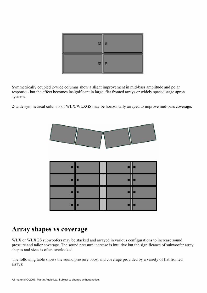
Symmetrically coupled 2-wide columns show a slight improvement in mid-bass amplitude and polar response - but the effect becomes insignificant in large, flat fronted arrays or widely spaced stage apron systems.
2-wide symmetrical columns of WLX/WLXGS may be horizontally arrayed to improve mid-bass coverage.
Array shapes vs coverage WLX or WLXGS subwoofers may be stacked and arrayed in various configurations to increase sound pressure and tailor coverage. The sound pressure increase is intuitive but the significance of subwoofer array shapes and sizes is often overlooked. The following table shows the sound pressure boost and coverage provided by a variety of flat fronted arrays:
All material © 2007. Martin Audio Ltd. Subject to change without notice.

Array Approx Boost Horizontal Vertical (wrt single unit) coverage coverage
- Wide Wide
+12dB Wide Narrow
+12dB Narrow Wide
+24dB Narrow Narrow In these examples “wide” means that there are no coverage nulls within the forward 180º at mid-bass crossover frequencies. Wide coverage arrays have significant output beyond 180º making them more prone to room colouration.
“Narrow” means that coverage will drop significantly before 180º coverage is reached at the mid-bass crossover frequency. General rules:
The larger the array the more directional it becomes A larger, directional system will be less affected by the room We get a 6dB far field sound pressure boost every time we double the number of cabinets.
Stacking safety! Stacked WLX or WLXGS subwoofers should always be blocked, strapped and anchored from above by a qualified rigger.
All material © 2007. Martin Audio Ltd. Subject to change without notice.

Coverage angle for tightly packed flat fronted arrays -6dB Coverage Here is a simplified formula for calculating the main coverage angle of a tightly packed flat fronted array.
* = approximate speed of sound in m/s. Varies with temperature (see Section 2a).
Arcsin means “the angle whose sin is ...”
Flat fronted cluster coverage patterns will be confined to one main lobe whose mid-bass crossover directivity is proportional to the size of the cluster.
All material © 2007. Martin Audio Ltd. Subject to change without notice.

The medium sized array (left) has significant output to ±90º whereas the large array’s ±90º output is dramatically reduced. A note on coverage nulls
It is useful to be able to calculate where these first response nulls will occur for various frequencies as they indicate areas where coverage, transient response and directional information would be poor without fill systems. For symmetrical arrays nulls will occur either side of the on-axis line. We can calculate the overall “null-to-null” angle using the simple formula:
As a very rough guide, the null-to-null angle will be approximately twice the -6dB coverage angle. Interpreting polar plots i) It is conventional to “normalise” polar plot on-axis amplitudes so that different polar shapes may be readily compared. In practice, the large array (right example) would have a higher on-axis amplitude than the medium array. ii) It is also conventional to plot polar amplitudes on a logarithmic scale. This is fine when working in sound pressure level terms but is not suitable for superimposing a polar plot onto a venue plan. Venue plans are drawn to a linear scale so polar plots with linear amplitude scales would be more suitable. iii) Polar plots have been simplified in this article for clarity. Real-world off-axis lobe amplitudes and shapes would vary considerably depending on boundary loading, echoes, reverberation and other audio sources affecting the same space. Vertical -6dB coverage The following table gives the approximate vertical coverage angles of typical WLX/WLXGS arrays - ignoring boundary effects (see later). WLX/WLXGS High Vertical coverage 47Hz 94Hz 188Hz
3 Wide Wide 98º 4 Wide Wide 69º 8 Wide 69º 33º 16 69º 33º 16º
Use tall stacks for long shots. Useful for long distances in low-roofed venues with raked seating up to the height of the stack.
Use short stacks for short, wide vertical shots. Use tall, electronically steered, stacks to project to high, distant seating – see later.
Vertical Boundary effects
As mentioned before, a solid floor will act as a reflector. This will cause a vertical stack to perform as if it were double the length, giving a useful low frequency boost and a narrower vertical polar response.
All material © 2007. Martin Audio Ltd. Subject to change without notice.

For instance, an 8 high ground-based stack of WLX/WLXGS subwoofers will act like the top half of a 16 high stack. It is possible to reach higher seating areas whilst retaining a tall vertical stack by electronically “tilting” the system - see later.
Note that flexible floors may actually absorb sound at some frequencies so the situation isn’t always so simple in practice. Horizontal - 6dB coverage The following table gives the approximate horizontal coverage angles of typical WLX/WLXGS arrays - ignoring boundary effects. WLX/WLXGS Wide Horizontal coverage 43Hz 86Hz 172Hz
2 Wide Wide 75º 4 Wide 75º 35º 8 75º 35º 17º 16 35º 17º 9º
Use wide arrays for long shots. Useful for long, narrow venues Use narrow arrays for short, wide shots
Horizontal Boundary effects
A solid wall near an array will act as a reflector. This will cause a horizontal array to perform as if it were twice as wide, giving a useful low frequency boost accompanied by a narrower, more complex polar response.
All material © 2007. Martin Audio Ltd. Subject to change without notice.

Again, a flexible side wall may absorb sound at certain low frequencies. Boundaries should always be treated with caution. Spacing It is possible to space out WLX or WLXGS subwoofers to provide a larger frontal area with fewer units but care must be taken to avoid irregular coverage at higher, mid-bass frequencies. The following formula gives the pressure ratio p(h) (wrt to the on-axis pressure) for any off-axis angle of a regularly spaced linear array:
All material © 2007. Martin Audio Ltd. Subject to change without notice.

Far field polar patterns can be quite complicated - even for a simple pair of subwoofers driven in unison.
Wide spacing will cause off axis irregularities (combing) because time offsets start to become significant.
An odd number of half wavelengths will cause nulls along the line of the loudspeakers (the 90º lines) - see the 2½ wavelength example above.
An even number of half wavelengths will cause lobes along the line of the loudspeakers - see the 2 wavelength example below.
The following tables give the maximum recommended gap (between WLX/WLXGS sides) for the relevant frequency range.
Gap Smooth coverage range
0.0m 38 - 160Hz 0.5m 38 - 115Hz 1.0m 38 - 86Hz 2.0m 38 - 60Hz To avoid combing...
Keeps gaps below 0.2m.
All material © 2007. Martin Audio Ltd. Subject to change without notice.

Horizontal splays
Splaying WLX/WLXGS arrays horizontally will widen their mid-bass coverage. The following sketch shows an 8 wide x 3 high WLX/WLXGS array arranged in four symmetrical pairs for smooth mid-bass coverage.
WLX/WLXGS Wide Horizontal coverage (Splayed with Radius = width) 43Hz 86Hz 172Hz
2 Wide 90º 60º 4 90º 60º 30º 8 60º 30º 36º 16 30º 36º 40º Note that lower frequencies remain focussed when large arrays are used with large radii. Smaller systems with small radii will widen coverage at all frequencies but may cause cause low frequency build-up on thrust and island stages. Avoid this problem by augmenting small stage corner systems with WLXs placed along the stage apron. For a smooth polar crossover:
Array the WLXs to match the curvature of the main clusters' low-mid or mid-bass section whenever possible but avoid making the front horizontal gaps greater than 200mm.
Avoid large gaps between the main system and the WLXs whenever possible.
All material © 2007. Martin Audio Ltd. Subject to change without notice.

Stacked WLX/WLXGS application examples The following sketches show how WLX/WLXGS arrays may be deployed for a wide range of productions and types of venue. All productions and venues present their own unique requirements and these examples are intended as a template or starting point for your own specific design. Examples 1 and 2 show typical set-ups for smaller venues.
(1) WLX/WLXGS set-up for small, high power variety/orchestral production
WLX/WLXGS arrays shown with front fiulls Gives medium vertical & wide horizontal coverage up to 120Hz - allowing for ground effects.
Example 1 uses small stacks of WLX/WLXGS for a high power variety or orchestral production.
(2) WLX/WLXGS set-up for small, very high power dance/rock production
WLX/WLXGS arrays – again shown with front fills Gives very narrow vertical & wide horizontal coverage up to 120Hz - allowing for ground effects.
Example 2 shows a tight vertical set-up for a very high power dance or rock event where it is desirable to keep low frequency energy concentrated on the audience for maximum bass/mid-bass punch without excessive roof excitation. Note that the apron WLX/WLXGS arrays are there to provide smooth nearfield coverage, balance backline leakage and keep the overall sound image locked onto the stage. The closer spacing, used for the very high power set-ups, helps maintain bass/mid-bass focus out to the midfield/mix position.
All material © 2007. Martin Audio Ltd. Subject to change without notice.

(3) WLX/WLXGS set-up for very high power dance/rock production in narrow arena
Gives narrow horizontal & vertical coverage up to 120Hz - allowing for ground effects. Example 3 shows a very high power dance or rock set-up for a narrow “shoe box” venue. Note the four-wide left and right WLX arrays for tight horizontal control and the more tightly packed apron systems for central focusing.
(4) WLX/WLXGS set-up for very high power dance/rock production in wide arena
Gives wide horizontal & very narrow vertical coverage up to 120Hz - allowing for ground effects. Example 4 shows a similar set-up - but this time for a wider venue. Note the narrower left and right WLX/WLXGS stacks for wider horizontal coverage.
All material © 2007. Martin Audio Ltd. Subject to change without notice.

(5) Alternative set-up for wide venues
Splayed WLX/WLXGS arrays for wide horizontal coverage. Example 5 shows a set-up for a TV shoot in a similar wide venue where sight-lines are critical. Note the lower profile, splayed arrays. Thrust stages Examples 6 show a typical set-up for a large, thrust stage productions.
(6) WLX/WLXGS set-up for high power production on large thrust stage
front view
side view
Gives medium vertical & wide horizontal coverage up to 120Hz for audience on 3 sides - allowing for ground effects. Again, left and right WLX/WLXGS arrays (but this time at front and rear) are augmented by apron fills. The system set-ups may be thought of as three-sided versions of examples 3 and 5.
All material © 2007. Martin Audio Ltd. Subject to change without notice.

Island stages (not shown) Island stages are simply four-sided versions of examples 3 and 5 and should be aligned using the same process. Tutorial on spaced systems Whenever two or more loudspeaker systems are fed with the same signal and their coverage overlaps, sound addition and subtraction will take place depending on the listener’s position. In the following example, the off-axis listener may hear delayed sound from the right hand system.
The two loudspeakers are driven in phase (both were +ve just before the instant shown) but the extra distance travelled by the second (R) signal causes it to be out of phase at the listener position at that particular frequency (R is -ve while L is +ve). Reflections Remember that a strong side wall reflection will act like a second source and the direct and reflected signal will combine as if they were two sources. The following illustration shows what will happen. The direct signal will combine with the reflected signal as if it were a phantom source in the position shown.
All material © 2007. Martin Audio Ltd. Subject to change without notice.

Addition & Subtraction
The above shows how two pairs of sine waves (with identical amplitude and frequency characteristics) will sum. Pair (a) are in phase and add. Pair (b) are out of phase and cancel.
All material © 2007. Martin Audio Ltd. Subject to change without notice.
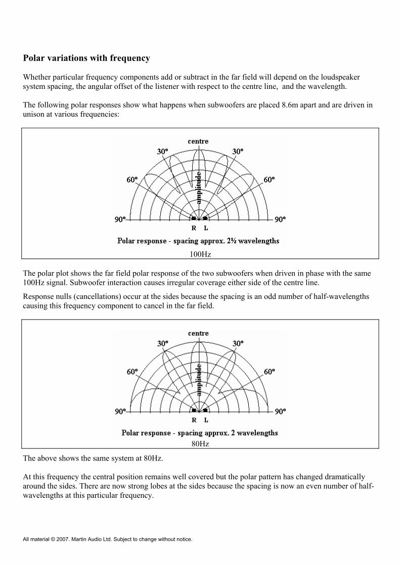
Polar variations with frequency Whether particular frequency components add or subtract in the far field will depend on the loudspeaker system spacing, the angular offset of the listener with respect to the centre line, and the wavelength. The following polar responses show what happens when subwoofers are placed 8.6m apart and are driven in unison at various frequencies:
100Hz
The polar plot shows the far field polar response of the two subwoofers when driven in phase with the same 100Hz signal. Subwoofer interaction causes irregular coverage either side of the centre line.
Response nulls (cancellations) occur at the sides because the spacing is an odd number of half-wavelengths causing this frequency component to cancel in the far field.
80Hz
The above shows the same system at 80Hz. At this frequency the central position remains well covered but the polar pattern has changed dramatically around the sides. There are now strong lobes at the sides because the spacing is now an even number of half-wavelengths at this particular frequency.
All material © 2007. Martin Audio Ltd. Subject to change without notice.

These lobes could cause low frequency feedback problems on stage with the high microphone gains used for orchestral low string (cello, double bass) sections or for “unplugged” performances.
60Hz
At 60Hz the spacing is an odd number of half-wavelengths again so we see side nulls again.
40Hz
When the frequency drops to 40Hz, the 8.6m spacing = 1 wavelength.
Again, the central response is maintained but there is a dip in response over wide areas either side of the centre. The spacing is an even number of half-wavelengths again so we see side lobes again.
All material © 2007. Martin Audio Ltd. Subject to change without notice.

40 Hz reduced spacing
The above shows what happens at 40Hz if we reduce the spacing between the subwoofers to 4.3m. We get better central coverage without 40Hz side lobes - adequate for long, narrow “shoe-box” venues but wider coverage would be required for most arenas.
40Hz close coupled Close coupling would give a wider coverage at that frequency but the spacing could still give coverage irregularities at mid-bass frequencies due to the shorter wavelengths at higher frequencies. The real world Bass notes usually include harmonic components each with a different wavelength. Some will add giving an amplitude peak whilst others will subtract giving an amplitude dip. This will give tonal changes with listening position and emphasise particular notes and timbres. In the following example, listeners over a wide central area will hear a warm bass note rich in harmonics whereas those around the sides (in line with the subwoofers at 90º) will hear less of the fundamental but more of the harmonics whose full wavelengths coincide with the subwoofer spacing.
All material © 2007. Martin Audio Ltd. Subject to change without notice.

Listeners in the 60º zone will hear the note at a reduced level and may be more aware of room reverberation because the direct-to-reverberation ratio would be poorer for that note. Other notes would give different effects. In practice, these peaks and troughs can be smoothed out with additional fill systems.
Electronic steering It is possible to “aim” ground-stacks towards distant raked seating or balconies or away from problematic areas by electronically “tilting” the system using multi-channel digital delay lines. The following illustration shows the basic schematic plus the staircase effect** (greyed out) produced by the progressive increase in drive delay from bottom to top. **Important Note:
The staggered stack (shown greyed out) illustrates the effect of electronic steering.
For safety reasons, never try to tilt or stagger a real subwoofer stack.
All material © 2007. Martin Audio Ltd. Subject to change without notice.

Note that it is important to keep the subwoofers tightly packed to avoid polar anomolies caused by spacing. Procedure The normal procedure is to measure the angle from the top of the vertical subwoofer stack to the highest/most distant seats (using an inclinometer) and to calculate the required delay increment with the formula shown. Example We wish to project bass/mid-bass punch to stadium balcony seats 30º higher than the top of our WLX stacks. The WLXs are 490mm wide giving a centre-to-centre spacing of 0.49m. This means that our delay increment (in ms) = tan 30º x 0.49 x 1000 340 = 0.577 x 0.49 x 2.94 = 0.83mS or 830uS.
All material © 2007. Martin Audio Ltd. Subject to change without notice.

The following delay line taps would be required for the above system: t0 = 0ms t1 = 0.83mS t2 = 1.66mS t3 = 2.49mS t4 = 3.32mS t5 = 4.15mS t6 = 4.98mS Going further It is possible to apply electronic shaping to horizontal arrays. For instance, it is common to use curved main clusters for smooth mid and high frequency coverage. Ground-based subwoofer arrays should follow the same curvature to maintain mid-bass crossover coherence but this is often difficult due to flat-fronted stage structures. The following illustration shows an example of a flat-fronted horizontal array electronically splayed to emulate the grey-out example shown.
All material © 2007. Martin Audio Ltd. Subject to change without notice.


![5V^5Vp - Chalmersrjmh/Papers/arrows.pdf®qfZ]\5W2e5dY\9Zn\5V _a^?V j´WlX®r5mnWYd2mnjYtutH_cU5d´vA_fZ]\±oRWYtS 5_fU j{Z]W2mn`h_c`H³7e5_ ZnV-W2qc^[ Zn\5V^5Vp `b_cdYU¡WlXoRWYtS](https://static.fdocuments.us/doc/165x107/60bfb2fda08b7943853dc5b6/5v5vp-rjmhpapersarrowspdf-qfz5w2e5dy9zn5v-av-jwlxr5mnwyd2mnjytuthcu5dvafzorwyts.jpg)


![WLX-2001 Range Extender N300 [Full Manual]](https://static.fdocuments.us/doc/165x107/62589589e5f63e1b50694db7/wlx-2001-range-extender-n300-full-manual.jpg)