WIRELESS SOLAR POWERED SURVEILLANCE …downloads.rhinoco.com.au/vswsc-manual.pdfWIRELESS SOLAR...
10
MODEL: VSWSC WIRELESS SOLAR POWERED SURVEILLANCE CAMERA WITH PASSIVE INFRARED MOVEMENT SENSOR INSTALLATION MANUAL V1.0 N517
Transcript of WIRELESS SOLAR POWERED SURVEILLANCE …downloads.rhinoco.com.au/vswsc-manual.pdfWIRELESS SOLAR...

MODEL: VSWSC
WIRELESS SOLAR POWERED SURVEILLANCE CAMERA WITH
PASSIVE INFRARED MOVEMENT SENSOR
INSTALLATION MANUAL V1.0
N517
1
INTRODUCTION
It has often been difficult for a DIY Handyperson to even consider installing an outdoor surveillance camera system – until
now!
Using a combination of Solar and 2.4GHz Wireless Video Technology, the Watchguard� Model VSWSC provides a revolutionary solution that is unequalled in its ease of installation and use.
Simply mount the Weatherproof Solar Powered Camera with Inbuilt Microphone & PIR Sensor to your wall in a sunny
position. The Camera / PIR can be rotated to view the desired surveillance area. No power connection is required for the
camera as it is powered by an internal battery that is charged automatically from the solar panel. The Indoor Audio / Video
(AV) Wireless Receiver simply connects to an AV input on your TV or VCR. Your outdoor surveillance system is now
ready for use!
To avoid wasting energy, the Camera remains on standby mode until body movement is detected by the camera’s built in
Passive Infrared Motion Sensor. The Camera then activates and sends the video and audio signals to the supplied AV
Receiver connected to your TV or Monitor for 10 – 40 seconds (selectable). The camera will keep sending a signal while
ever movement is being detected and as long as there is sufficient power in the built-in battery.
On the AV Receiver, an indicator light illuminates and a buzzer sounds (can be switched off) to advise you that the PIR
Sensor has detected movement and your camera is now active. By selecting the appropriate AV channel on your TV you
can now see and hear anything within range of the camera.
The components included in the VSWSC Solar Camera Kit:
1 x Solar Camera with PIR and Solar Panel (Transmitter)
1 x Audio & Video Receiver
1 x Power Adapter for Receiver
1 x 3 Feet RCA AV Connection Cable
1 x 6V 1.2A Rechargeable Battery
1 x 9V Alkaline Battery
1 x Waterproof Rubber Plug
2
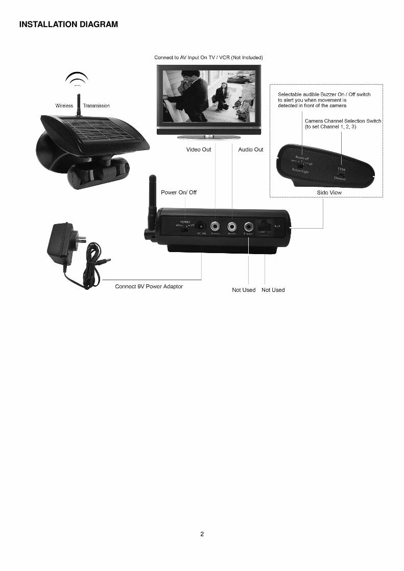
INSTALLATION DIAGRAM
3
BEFORE COMMENCING INSTALLATION
Please pay attention to the following factors before you commence installation:
1. Camera location with sufficient daylight: The camera solar panel requires exposure to direct sunlight during
daylight hours to provide sufficient charge to the internal battery. Please mount the camera in a sunny
location where it will receive at least 3 – 4 hours per day of direct sunlight.
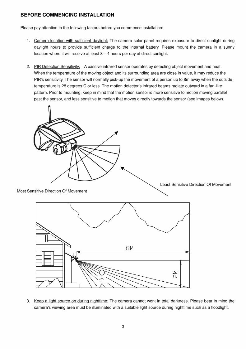
2. PIR Detection Sensitivity: A passive infrared sensor operates by detecting object movement and heat.
When the temperature of the moving object and its surrounding area are close in value, it may reduce the
PIR’s sensitivity. The sensor will normally pick-up the movement of a person up to 8m away when the outside
temperature is 28 degrees C or less. The motion detector’s infrared beams radiate outward in a fan-like
pattern. Prior to mounting, keep in mind that the motion sensor is more sensitive to motion moving parallel
past the sensor, and less sensitive to motion that moves directly towards the sensor (see images below).
3. Keep a light source on during nighttime: The camera cannot work in total darkness. Please bear in mind the
camera's viewing area must be illuminated with a suitable light source during nighttime such as a floodlight.
Most Sensitive Direction Of Movement
Least Sensitive Direction Of Movement

4
Installation
Step 1: Installing The Camera
a. Carefully cut & remove the plastic binding strap that is holding the backplate to the main camera body and then remove the backplate from the rear of the camera housing. An image of the backplate is shown above.
b. You will see on the backplate both a large 6VDC battery and a small 9V DC Battery. Connect the large red and black battery wire leads for the 6VDC Battery to the corresponding colour terminals on the battery.
c. Remove the 9VDC Battery by unscrewing the battery hold down strap. Remove the plastic protective wrap and then replace the battery. Now connect the 9V Battery to the clip-on connector. IMPORTANT: The 9 Volt Battery is only intended for temporary use to ensure sufficient power is available for you to set-up the initial installation and give the solar panel sufficient time to charge the large 6VDC Battery. The 9 Volt battery should be removed within 1 month of installation, otherwise if left in place it may leak and damage the systems electronics. This is not covered by warranty.
d. Adjust the “Transmission Time Switch (SW3) to select the transmission time of video and audio when the PIR senses movement. It can be set as either 10,20,30 or 40 seconds. Please consider how often movement is likely to be
detected in your installation. The shorter you set the transmission time the less power will be used from the battery, and
the less sunlight will be required to recharge. In most installations 20 seconds transmission time should be adequate.
e. Adjust the “Channel Selection Switch (SW2) to select which channel you want your system to transmit on. (In Australia you must only use channels 1, 2 or 3. DO NOT USE CHANNEL 4). Make sure you remember which channel you have
Battery Hold Down Strap
Channel Selection Switch (SW2)
Transmission Time Switch (SW3)
Reset Switch (SW1)
Optional Input For 9VDC
300mA Plugpack

5
selected.
f. Use the fixing template provided to mark the position of the four backplate fixing holes. Drill four 5mm-diameter holes. Note: If mounting onto a brick or cement surface, you will need to insert suitable wall anchors for that type of surface. If
mounting onto wood or a non-brick surface, you can use the wood screws included.
g. Mount the backplate by inserting two screws into the fixing holes on the top edge of the backplate only.
h. Once you have securely fixed the backplate to your wall, plug the camera’s 12 Pin ribbon cable into the socket on the backplate. The connector plug is keyed, and will only insert one way. (The red wire should be to the left).
i. Now secure the camera body to the backplate by hooking the lip on the top edge of the camera body over the top edge of the backplate and lowering into place.
j. Now insert screws into the two fixing holes on the bottom edge of the camera and tighten. Once secured in place, insert the waterproof rubber plug supplied into the hole at the bottom of the front cover.
k. The camera and PIR (which are under the main solar panel) can be swiveled upward to 5°, downward to 45° and 90° horizontally. Adjust the camera / PIR angle according to your need.
Step 2: Installing the AV Receiver Unit
To connect the receiver to your TV / VCR:
1. Plug the yellow (video) and white (audio) RCA connectors into
an available AV input on your TV / VCR. Set your TV/VCR to the
AV Input you have chosen (refer to your TV/VCR Manual)
2. Plug the yellow (video) and white (audio) RCA connectors into
the corresponding RCA connectors on the receiver & raise the
antenna to the vertical position.
3. Connect the low voltage AC power adapter to an available power
point, connect the plug on the lead to the DC Jack on the
receiver and then switch on.
4. Set the channel selector switch to match the channel you selected on your camera (1, 2 or 3).

6
Operating Instructions: (1) Buzzer/Light ON/OFF Switch: The Buzzer / Light Switch has three selectable positions:
"ON" In the left switch position, when the PIR camera detects movement, video and audio will be automatically
transmitted to the receiver. Upon receiving the signals, the receiver beeps twice and the Trigger LED on the front of the
receiver will flash for 1 minute.
“Buzzer Off” In the center switch position, only the Trigger LED on the front of the receiver will flash for 1 minute when
the PIR camera detects movement. There is no audible sound indication.
“Off” In the right switch position, there will be no light or beeps activated when the camera detects motion.
(2) When the PIR of the camera is triggered by movement, the camera will send the 2.4GHz RF radio signal to the
receiver. Video and Audio will then be displayed on your TV / VCR via the receiver.
(3) Remember that the transmission time of video and audio can be set within the camera for 10, 20, 30, or 40 seconds
upon each PIR movement activation.
(4) When the transmission time is over, the camera will only continue sending video and audio if the PIR sensor is still
being triggered by movement. Otherwise, the camera will stop sending video and audio to conserve power.
(5) When the solar rechargeable camera battery is low:
a. The camera will send a signal to the receiver to turn on the “Low Battery” LED and will also sound two beeps as an
alert.
b. If the battery level is low during image transmission the image will stay on screen for 5 seconds only. There will
also be two beeps heard and the “Low Battery” LED will remain on.
c. When the camera is recharged to normal level, the low Battery LED will be turned off when the camera is triggered
again.
Optional Use Of Mains Power Adaptor (Not Supplied) For Continuous Camera Transmission:
Although this system has been designed to run off solar power & only display video when PIR movement is detected, you can make
the system continuously transmit the video / audio signal to the receiver by connecting a 9V DC 300mA regulated AC power
adapter. Simply connect the positive (+) side of your 9VDC supply to the left hand screw terminal and connect the negative side (-)
to the right hand side screw terminal.

7
OPTIMIZING THE WIRELESS SIGNAL The 2.4GHz video signals pass easily through your home’s interior walls, but the signal may be reflected by power wires
or plumbing inside the wall. Usually a slight adjustment of the Receiver and/or Camera will improve reception. The most
common source of interference are microwave ovens. Try to avoid mounting the Receiver near a microwave oven or
other source of RF interference such as cordless phones.
TROUBLESHOOTING:
(1) If the camera does not work properly:
a. Unscrew the camera (two screws on the bottom edge of front cover)
b. Locate and press the reset switch “SW1” to restore the system
c. Replace the camera on the wall mount, and tighten the 2 screws on the bottom of the camera.
d. Turn off the receiver, then turn it back on. If system still does not operate correctly, call the Watchguard Help Desk
on 02 4577 4708 (In Australia)
(2) Remember, if the camera battery has a low charge, the video transmission time automatically reduces to 5 seconds
to save the battery until it is recharged.
(3) Make sure the camera and receiver are both set on the same channel.
(4) When the image on the TV is not clear, it may mean that somebody may be using the same channel as yours in your
neighbourhood. You should change channels. Remember to set the camera on the same channel as that of your
receiver.
IMPORTANT NOTES REGARDING 2.4GHZ WIRELESS VIDEO SYSTEMS & PICTURE QUALITY There are a number of environmental factors which can cause either temporary or prolonged signal interference to
2.4GHz wireless video systems. Quality of signal can be reduced by:
Physical objects (particularly metal) being in the direct transmission path between the camera & receiver.
Other 2.4Ghz wireless devices being used in you local neighbourhood such as Wireless Computer Networks
Strong signal emissions from local power lines, mobile phone towers etc
Radio interference caused by “noisy” motors or compressors in some older electrical appliances
Some microwave ovens whilst in operation
You may not be able to achieve a perfect signal in your local environment, and some interference should be expected as normal.
HELP DESK: Phone (02) 4577 4708 9am – 5pm Mon-Fri

8
SPECIFICATIONS Made In China Camera Receiver Picture Type Color CMOS TV System PAL Transmission Range Up to 100m in open space Sensitivity [email protected] Channel Selection Switch 3 positions for 1~3 selection Lens Angle 78° Diagonal Lens 4.3mm F2.0
Buzzer & Light Switch 3 positions for buzzer & light on / buzzer off/off
Camera Angle Left & Right 90° 5°, Down 45° Power Switch 2 positions for power on / off Microphone Built-in Triggered Buzzer & Light function Built in Transmitting Frequency 2400~2463MHz (for 3 channels) Antenna Type Rod
AC Adapter 12VDC, 500mA AC adapter Battery 1 x 9V back up battery, 1x 6V
rechargeable solar battery Transmission Time Switch 4 positions for 10s/20s/30s/40s
Power Supply Source Solar Panel (110*160mm) Channel Switch 3 positions for 1~3 selection PIR Detect ion Distance/Angle 8M/90° (under 28°C)
Connector 1 x DC Jack for Power 2 x RCA Jack. Audio (white), Video (yellow)
Limited Warranty RhinoCo Technology (Seller) warrants its products to be in conformance with its own plans and specifications and to be free from defects in materials
and workmanship under normal use and service for twelve months from the date of original purchase. Sellers obligation shall be limited to repairing or
replacing, at its option, free of charge for materials or labor, any part which is proved not in compliance with Sellers specifications or proves defective in
materials or workmanship under normal use and service. Seller shall have no obligation under this Limited Warranty or otherwise if the product is altered
or improperly repaired or serviced by anyone other than Seller.
For Warranty Service: Return transportation prepaid with a copy of your purchase receipt and contact details to:
RhinoCo Technology, 9 Hannabus Place, McGraths Hill, NSW 2756 Australia.
Seller has no obligation to attend the buyer’s location to retrieve the goods or make repairs onsite.
• There are no warranties, expressed or implied, of merchant ability, or fitness for a particular purpose or otherwise, which extend beyond the
description on the face hereof. In no case shall seller be liable to anyone for any consequential or incidental damages for breach of this or any
other warranty, express or implied, or upon any other basis of liability whatsoever, even the loss or damage is caused by its own negligence or fault.
• Seller does not represent that the products it sells may not be compromised or circumvented; that the products will prevent any personal injury or
property loss by burglary, robbery, fire or otherwise; or that the products will in all cases provide adequate warning or protection. Customer
understands that a properly installed and maintained alarm system may only reduce the risk of a burglary, robbery, or fire without warning, but it is
not insurance or a guarantee that such will not occur or that there will be no personal injury or property loss as a result.
• Consequently, seller shall have no liability for any personal injury; property damage or other loss based on a claim the product failed to give any
warning. However, if seller is held liable, whether directly or indirectly, for any loss or damage arising under this limited warranty or otherwise,
regard less of cause or origin, seller's maximum liability shall not in any case exceed the purchase price of the product, which shall be the complete
and exclusive remedy against seller.
This warranty replaces any previous warranties and is the only warranty made by the Seller on this product. No increase or alteration, written or verbal,
of the obligations of this Limited Warranty is authorised.

9
FCC Radio Frequency Interference Statement
This equipment has been tested and found to comply with the limits for a class B digital device, pursuant to Part 15 of the FCC Rules. These
limits are designed to provide reasonable protection against harmful interference in a residential
installation. This equipment generates, uses and can radiate radio frequency energy and, if not installed and used in accordance with
the instruction, may cause harmful interference to radio communications. However, there is no guarantee that interference will not
occur in a particular installation. If this equipment does cause harmful interference to radio or television reception, which can be
determined by turning the equipment off and on, the user is encouraged to correct the interference by one or more of the following
measures:
-- Reorient or relocate the receiving antenna.
-- Increase the separation between the equipment and receiver.
-- Connect the equipment into an outlet on a circuit different from that to which the receiver is connected.
-- Consult the dealer or an experienced radio / TV technician for help.
CAUTION:
Any changes or modifications not expressly approved by the seller of this device could void the user's authority to operate the
equipment.
… ………………………………………………………………………………………………………………………………………..……