WINGED EDGE POLYHEDRON REPRESENTATION BY BRUCE G. …
54
ARTIFICIAL INTELLIGENU )“KUJtLI WINGED EDGE POLYHEDRON REPRESENTATION BY BRUCE G. BAUMGART SUPPORTED BY ADVANCED RESEARCH PROJECTS AGENCY ARPA ORDER NO. 457 OCTOBER 1972 COMPUTER SCIENCE DEPARTMENT School of Humanities and Sciences STANFORD UNIVERSITY
Transcript of WINGED EDGE POLYHEDRON REPRESENTATION BY BRUCE G. …

ARTIFICIAL INTELLIGENU )“KUJtLI
WINGED EDGE POLYHEDRON REPRESENTATION
BY
BRUCE G. BAUMGART
SUPPORTED BY
ADVANCED RESEARCH PROJECTS AGENCY
ARPA ORDER NO. 457
OCTOBER 1972
COMPUTER SCIENCE DEPARTMENTSchool of Humanities and Sciences
STANFORD UNIVERSITY


t
.STANFORD ARTIFICIAL INTELLIGENCE PROJECTMEMO AIM-179
OCTOBER 1972
COMPUTtR SCIENCE DEPARTMENT REPORTNO, LX-320
WINGED EDGE POLYHEDRON FW'RESENTATICVG,
Bruw C, hungatt
Abstract: A winged edge Polyhedron remesentatlon ‘ts stated anda set of orimetrves that ~roserv@ Euler's F-E+V = 2 eauatlon areemPined, Present US@ of this reptesentatton :n Att’fficialIntBll lgence for computer graphic3 and world modeling !g ~Ilustratedand its Intended future appbation to comwter vision is dkciibed,
CONTENTS
1, INTRODUCTION,A, Introduotlon to Wor!d Modelhh8, Introduction t o a Camera Model,C, Introduction to BodY, Face, Edge, Vertex Wodeling,
II, . DATA STRUCTURE of Wllrrged Edge Polyhedra, 'A, Winged Edge Structurec8, Wtnged Edgo Omrat~ons,C, Elaborations
III, PRIMITIVES on Polyhedra8A, Euler Prtm~ttves,8, Salld Prlm\tfves,C , Geometrk Prtmbb’?S,0, Image Formlng Primltlve8,
IV,.APPiICATIONS,
Modelfngt GEOMED - 1 30 drawlng 0dltor,B: GraOhbst OCCULT 0 8 hIdden Iine elld+tor~C, vldonl CAREYE - l vld@o region-edge ffnder,
This reaerroh was supported In Dart by the Advanoed Resesrch ProJectsAgency of t h e 0Wce of t h e Secrstaiy of Defence under contractSD-183,

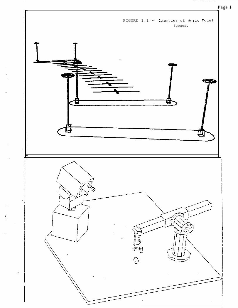
FIGURE 1.1 - L‘xamples of World T’odclScenes.
Page 1.
\
\ ‘I
. \


PAGE 2
I. INTRODUCTION,
In order to get a oomputer to deal with the phYsIcal world itmust have a data repreaentatlon o n which commutations ~nvolvf&SDaCe, the, shape, size, and the atmeayanoe of things can be done,It is my current preJudice that pbiyhedra provide the DroDer startinaoolnt for buildhg such a ohysioai world rfvmmentation, At StanfordArtlfiCial Intellegencer Binford and Agin have started lrrstead wjth.spine-cross sectlon models as an alternate approach t o the sameoroblems CrefVenoe 13, Other researchers with somewhat differentgoals, are attembting to build wmantic, predicate calculus, problemr
.- SolVi,3#akt
starte3Y Piann i B World models, In anY ava,tr this0aPer Is a hod\ )
cfaae, a8 g% vertex Doi
rhedton mode I that is
for m0dellns objet s and saenes of oojects or the sake of computervision8
Although the data stru0ture to be discussed is not lan9uagedeaendmt, t h e terminlogy and examples will follow ALGOL and LISP.Alsop the reader is assumed to have dome acquaintance with the 1 deasassociated with the following technical terms!
.A: block, node, item, element, atom,R: link, Dointer, addyes reference,C: datum, content, value,0: bt, ring, stack, odl, tree,E: dynamic free storage 8 memory allocation,
.A thorough presentation O f these terms and ideas can be found inchapter two of volume one of Knuth's cookbook, 'The Art of ComDUterPrOgramrrfng' [Reference 73, The word Vin9" used informally in thkpaper will always mean a double pointer ring with a head; and as inLISP, words of memory happen to be able to hold two pointers.


Page 3 1
FIGURE 1.2 - A Polyhedron Model of a t!echanical Arm.
-.
-- . _. I___ --_---_.--_- -. -_. ----.----. _--_--- - - _- - .-- --- - _- .__+--a- -A .--m-.-e-
i
. ._- I.- - -- -.
__.v---Me---.... -. a- --we _ _“_._--- w--e
.- . . ..---- --.- -. __._,_._. - ,- -*

PAGE 4
I, At Introduction to World Modelbb
I will tntroduce my rQgulr@m@nts for a computer m o d e l of ihemdcal world In tetms of its role as a mqmoryc As a memory0 awar Id model has contents and an addresslne meohanlsm, The kinds ofdata that I wish to hold in my wo?ld model aret
.CONTENT REQUIREMENTS6 1, Topoiogloal data,
2, Ceometplo data.3, Photomettlo data,r
.' 4, Parts tree data,
Topolodcal d a t a h a s t o do with the notion& netghborhoodj aworld modal has data on what is next to what. A edge, vertexm o d e l 1s esssntially dedfcated to sutfrca toPoloeYt mktters of Volumetopology are not stored but rather must be computed, Geomettto datahas to do wtth notions such as looua, length, area and volume,PhotometrIc data includes the loous and nature of light sources~ a swel( as data on how surfaoes refleot, absorb and seratter Ilght, Partstree data has to do with the notton that obJeots are corndosed ofD a r t s , whloh 1 c o n s t r u e a s data on the structure of the physIcalworld rather t h a n a s purely a n adfact o f having structured World
.datai that is, 1 p r e f e r to have the sprclfkatfon of how an entltY 1sbroken into part; be external to my world model, The kinds 09 datanot Included are semantlo data (other than body names); ohysfcal datasuch as mass, tnertja tensors, eleotrlaal propertIes and so on! andoultural data such as whether an obJeot Is a toy, tool, 0; weePoWwith a n y artlstlc, rejlgfous or market value,
.Next the kinds of addrsssln
?mechanisms I wish to have, (of
eaulvaiently the input-output modes o the model) are:
ACCESSING REQUIREMENTSa 1, Appearance - given a camera8 return an image Ofwhat the world would look like from that camepa,
2, Recognition - given an image, return the obJectaI from the world model t h a t apB8ar in that !;;M:.
3 , Camera Solution - sahen a recognizedfind the looation 6 otlentatlon of the camera:
4 , PercrPtlOn - given frnag~3, from solved camwas,.’ plaoe new bodlee into the model for ooit!ons of
the images that have not Yet been recognlxed,5 , Saattal Accessing - 9lVen a locus and radius,
return the Portions of obJects In that sphere,
ClearlYt these are the high level acoesslng rqoulrements whfoh arethe reasona for having a world model and the dsskn goals for modelbut Wing,
PAGE 5
image sqeen
lens center
FIC,I!W 1.3 - A Camera Tiodel.
FIGLIZ 1.4 .- Logical and Physical Fr-\ster Sizes.
LDY = 12rows
PDY = 2.3"
IPAGE 6 *
I, 8, Introduction to a Camera Mod%
.
A s the accessingspecial
requirement;hs!;;ly,entltu called a camera
a world mode~l&uiree aIs used to I maw
formatIon, Although the camera model i8 important here for a comDl@tesp8clfication of the data, It mky be skipped on a first reading. Theoarthular oamera m o d e l I h a v e been using lately, 19 endressed b yOlQhte@n real numberg fnvolving nlns degr889 of freedom, Fbt there1s the camera lens center looust
r cx, CY# C& In world coordinates,.
AfIxed to the lens center Is the camera frame of reference with unitvectors I, J and k, when the hag8 formed by the camera 1.s placed incotresPondence to a display screen8 as \Ilustrated In figure 1,3, theUdt vector I maos into the rightward posftive x of the dlaplavscreen, and the unit vector J maos into the upward posltfve y of thedisplaY dcreen, and the unit vector k com8s out of th8 dlsolay screento form a rlgh-t handad ooordlnatr W9t8m, Together the three Unitvectors of the oamera are the three by three rotation matrlxt
IX, IY8 IiiJXI JYI Jz! In world aoordfnates,KX, KY, Ki!
NOW, there are three goal89 wht chbetween world 9fZe and Image site,
dstermlne the cor'espondenoeObserve that the world s m8aWkrdF
In phyrlcal units of length Ilk8 meters or feet while cornouter Imagescome In integral sizes llke 1024 bY 1024 or 480 rows bY 512 cblumns,thus th8 ConversiOn scales muat be In t8rms of logical Image un!t9per PhYsIcal world unit9, In an actual tel8vislon camera a minute1 mu8 (9aY 9mm by 12mmI Is formed on a vidfcon tube and that Imagehas a partioular number of rows and oolumns, It Is the ltttle imageon the vldkon that we pr8tend to model by the SIX Oatametersl
LOX, LDY, LDZ Loglcal roster 9128,POX, PDY, FOCAL Phy9lcal raster 9izee
Where the number nam8d FOCAL, 19 the focal plans distanoe which inthis model (wfth distant objeots) oan safely b8 equated with the lsnsfocal length and can be given in mlllfmet@rs (oonventional lens ;unU15mrn to 75mm for 1" TV). the fntrgrt LDtJs an artflract 90 thatthe units oome out correctly in the t dlmenslon, Thus the scalesfactor8 are deflned:
SCALEX * -FOCALwLOX/POWSCALEY c -FOCAL+LDY/PDY;sC4.O * FOCALeLDZj
This slmple camera model i9 used to oomoute vertex Ima ecoordinates, A more Waborat8 PhYslcal camera model can be found f nSobI [reference 9J,
PAGE 7
FIGURE 1.5 - A Renaissance Camera Model.
. - ---- -- _--. _- - ----
LensCenter
Z
___---L-L ;--
PAGE 8-1
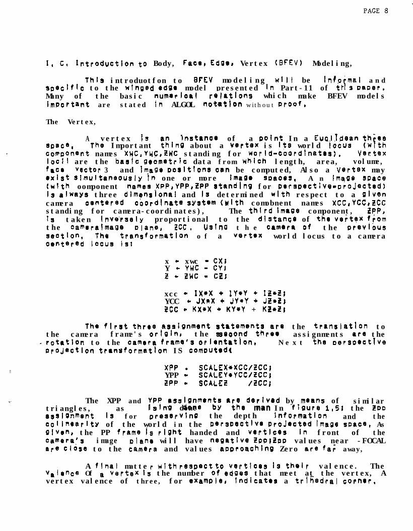
I, c, Introduction to Body, F~o@, Edge, Vertex (BFEV) Modeling,
Thla introduotfon to BFEV modeling wilt be info'mal a n dspecific to the nfnged edge model presented fn Part-11 of th s Lamar,FMany of the basic numerfoal WatIons which make BFEV modelsIimportant are stated in ALGOL notath without proof,
The Vertex,
A vertex is lnstanoe of a point In a Euolldean th-eespace, The Important $nQ about a V@rtW is Its world 'locus (wfthooflponent names XWC,YuC,ZWC standing for world-coordlnatrs), Vmtexlocl~ are the bask geometrk data from which length, area, volume,f&CQ "Qctor 3 and Image poslttons oun be computed, Also a Vertex mayexist slmultaneougly fn one or more Ima SP8083, A n Image space(with oomponent namee XPP,YPP,ZPP standing for perspect;Ye-D~oJected)13 always three dlmenrional and Is determined with respect to a givencamera oentered cbordjnate sYst@m Wth comobnent names XCC,YCCdCCstanding for camera-coordinates), The thtrd Image component, ZPP,1s taken lnve-rsely proportional to the distance of the ve;tex fromthe Camera lmaee Wane, zcc * Ustne t h e camera of the prevlbussectIon, The transformation o f a vertex world locus to a cameraoentQred locus is:
x - xwc - cx,Y - YWC - CYI2 - twc - CE;
xcc - 1x*x + IY*Y + IZ*trYCC * JX*X + JY*Y + J&G?,tCC * KX+X + KY*Y + KL*tj
the flr8t three a9slgnment rtrtemsn~;r~;e the translation tothe camera frame's dgh the ssoond assignments are the
a rotatlon to the camera frame9 orlQnt8tion, N e x t the dersDectTv9or0jQctlon transformat?on IS comwtad(,
3XPP l SCALEX*%CC/ZCC;
YPP + SCALEY+YCC/ZCCjZPP - SCALE3 /tee;
The XPP and ;;P#gnrnen;; ai;ederIved by mQan$ of similartriangles, as IS . done man In fbure 1,~; the ZDDaaSl9nment 1s for preservfnQ the depth jnformatlon and thecolinearlty of the world in the perspective prbJ*cted Image soace, Asgiven, the PP frame is rfght handed and vertices In front of thecaWra's image plan@ will have negatlv8 iEpp) Lpp values near -FOCALare Close to the CamQra and values aoproachlng Zero are fa; away,
A flnaf mattevalence Of a
r with respect to VQrtices 1s their valence. Thevertex 1s the number of edges that meet at the vertex, A
vertex valence of three, for e%amPb, Indicate8 a trihedral cornor,
PAGE 9
4, C8 Introduction to BFEV Model In& (cont'inued),
The LdSe,. .
For a start, the structure of an edge need be thought of aslittle core than two vertices; the togological subtlety of edges wf I Ibe axDlained later, HoWeVer~ two vertices do define the imDortantgeorretric edge data called the 20 llne coe'ffkients. Named PA, RB,cc; these coefficients are cornouted from the Oerspective locus of theedge's endpolnts as follows:
AA * Yl - Y2155 + x2 - x1;cc * Xl*Y2 - X2*Ylr
These coefficients aoDear In the 20 equatfon o f the J he thatcontains the edge:
--. 0 = AA+X + 55eY + CC;
Mhec the edge coefffcients are normalized:
L c SQRT(AAQ+!H*2);AA - AA/L;55 * BEIlL:cc * CC/L;
the line equation gives the distance, of a point X,Y from the line:
r3 + AA*X + B!3eY +XC;
The distance is actually AYS(Q), since Q is negative on one side sidecf the I he; atso if one were standing on the plane at Pornt Xl,Ylfacing x2,YZ the 2 oositive half-plane would be on your left and theG reaative half plane would be on your right.
An important ooeration on two edges is to detect whether orrot the> intersect: this can be decided by checkIn first whether theendtdints of one edge ate in the oooosite half planes of the otheredge ,‘ acd second whether the endooints of the latter edge ate In theopposite half planes of- the first. When both conditions obtain, thenthe intersection point can be found:
T + (Al*B2 - A2+Bl>;x * (Bl*CZ - 52NX,)/T;Y * (A2*Cl - Al*C2 l/T;
h7 acttat coware for- Intersection should initially check for theiaertity case, and for edges with a vertex in comon,
PAGE 10
I, L Introduction to BFEV Modeling, (Continued),
The Face,
A face is a, finite reglOn of Plan8 enclosed by stralehttines, A safe fmnal face structure could be built by def;ning aWangle as three non-oolin8rr vertices and then insisting that allfaC8S b e tr!-angle fntariors, Unhapol IY4 BFEV faces are usuallyreDresented as a ifst of vertioes and edge8 tot by something nea; ly~qutvahnt) for tha sake of saving memory space, Such $1 ie kc838r8 not monoifthlc but tend to suffer special cases and oathologlessuch a8:
Coincident or crossing edgesIHates and DfsJolntness,ConcavIty (6 Convextty),Non-coolanarlty,
Like edgm, faces have characteristic Oo8ffiCients Face coefficientssatlsfY the equation of a plan8 in whioh th8 faC8 1s embedded:
AA+X + BB*Y + CC*iS = KK,
The equation could be divided by KK, but that is undesirable becauseth8 AA@ BB, CC are more useful as a unft normal vector, ln which case‘KK Is the distance of the orlgln from the plane, Given the looii ofthree non-oollnear v8rtlC8sP th8 co8ffiCi8nts of a plane can becomput8d by Kram8r’s rule a s foiiowsr
KK c Xl+(t2*y3-Y2*Z3)+ Yp(X2*t3-i!2*X3)+ tl*(Y2*X3-X2*Y3U
AA c (zi*(y2-y3) + t24~~3-yt) + ZWYl-v2wBB - (Xl*(t2-t3) + x24wS-if11 + XWZl-t2mcc - (Xlqy3-Y2) + x24qYi-Y3) + x3*(Y2-ylm
and norvallzedt
ABC - sQRT(AA?2 + 8892 + CC92)jAA * AA/ABC;BB +, BBIABQcc + CC/ABC1KK c KK/ABC;
If the given vsrtlces VI, V2, V3 had been taken go;;; c;;y ;rciockwb a&out the face as viewed from the exterior of t 8th8n the following relattons Obtain1
AA*X + BB*Y + CC*2 < KK fmplirs X&t above the ilane,AA*X + BB+Y + CC*t = KK ImplIes X,Y,Z in the plane,AA*x + BB*Y + CC+g > KK Implies )(pY,I! below th8 plan&
Face coefflcignts prove-useful ln both world and hage Coohhat@s~

PAGE 11
-=.

1. c, Irtroduction to RFEV MoJelhg, (COntlnued),
POLYHEDRA, BODIES and OBJECTS,
In elementary geometry8 a d'olyhedron is said to be a solidforrred (or bounded) by plane faces; the word **polyhedton*~ literally7eanin9 "many-f aced", ToDoloSically, simple f3ofyhec;fa satisfyEuler's F-E+Vz2 equation; where F, E and V are the number of fbces,ed9eS and vertices of the polYhedron respectively, This eouatlon wasknown to Descartes in 16421, but the first proof Wasn't given Until1752r hhen Euler braved the relation by considering the graphCorresPondlng to the edges of polyhedra, 4 simple polyhedron 1s onehoreomorPhfc to a sphere, The rigorous development of VOlUne measure,and in turn ‘solid’ Polyhedra, is not simple; thus it has been eadarto take the tobologtcal notton F-E+V=2 a s the more prtmltlvedefinition of a polyhedron on which to base a data structure and t oorcceed toiJards t h e aPDearance o f ‘solidness’ wh 1 ch IS a morecompl icateo notion. --
anCounter to the usualuu;age, 1 define the word "body" to mean
entity more so&f ic a oolyhedron; the idea be;ng that aDolYheQon 1s reoresented by the whole StruCturB of bad/es, faces,e d 9e.s and vertices. Bodies may have location, orientat;on and volumein space, Bodies may be coqected to faces, edges and Vert(ces, wh I chffaY or nay not form a complete polyhedron, It is typical to haveonI3 one body to a bolyhedron when reDresenting a rigid object like asleage hammer and several bodies to a polyhedron when representing aflexible object Iike a man, Furthermore, the body concept 1s used t ohanole the notion of parts and abstract regional obJects such 8s aParking lot, iOr examgAs, the Stanford AI Parking Li>t iSrepresented by a body that has three bartst the Near, Mfd and FarLob The Near Lot then has aisles and lanes and lamp Islands; a lampIsland has a Wfkl and two laws; a lamb has a base, stem and too,This parts structure is carrted in body nodes, Final IY, the word'lobjBCt'v u\II b e used to refer to physical objects such as aredhood-tree, building, or roadway,

PAGE 13
CiQure 1‘6FAN PLRIMETER - a face is surrounded oy edges and V8ft;Ces.
VERTEX8 . .
/ \/ \
/ \/ \
EDGE / \ EDGE/ \
/ FACE \/ \
/ \/ \
VERTEX l --------------------.a VERTEXEDGE
figure I,7 k‘KRtk,X PER I METER’ - a vertex is surrounded by edges and faces,
EDC.EI
FACE I FACEI. VERTEX
/ \/ \
/ \/ \
/ FACE \EDGE EDGE
eFigure 1.8EDGE pERI@r~fl - an edge IS surrounded by 2 faces (P 2 vert?ces,
VERTEX
8II
FACE E F4CEII8
VERTEX

PAGE 14
1. c* Introduction to 8FEV Modeling, (oontinued),
FoUFi KINDS OF E;FEV aCCF-SSIrG,
1. Accessing by name and serial number.2. Parts-Tree kcesslng,3, FEV Seouentlal ACcesslng,4. FEV P8rifn8ter Accessing,
A BFEV mow3 I has four kinds of accessing, The mostconventional BFEV access is retrieval oy symbollo name which recUir8sa SYmbo I tabie, Next, between bodf8S there is Parts-Tree accessing,At the top of the Parts-Tr89 is a sp8cial body named the !world towhich all th8 other oodies are attached; thus the world body servesas an WLIST node, Given a partfcular body, a list of its sub-Partscan be retrieved as HeI 1 as its supra-part or %Upart'q, A suoart isthe khole entity to which a Dart belongs, the world being i tS ownsupart,
Within 8aCi b o w there 1s face, adge and vertex socuentlalaccessina, Given a body, all its faces, or edges, or vertices need tobe readily avajlab)e since oersoectlv8 orojectlon loops thtu all thevertices, and the orocess of disolay cl iDping i OODS ttTru al I the8dC?iS, and the act of checking for body intersection !oocs thru al Ithe faces, In LISCr one might DrOVld8 FEV Seouential nccessfng b yplacing a list of faces, a list of edges and e I Ist of vettiC8S onth8 Droperty list of each body, so that a cube night be reDresentedas:
(LEFPROP C&E (FL f-2 F3 F4 F5 t%) FACES)QEFpROp rU% (El F2 E3 E4 E5 E6 E7 EB E9 Elfl Elj, fl2)E~GcS)(DEF~RC~ :UGE WI V2 V3 V4 V5 'Jb V7 V8) VERTICES)
a Finally, avcms the faces, edges and vertices of a body thereis prirreter accessing, Faces have a perimeter of edges and vertices[fistire 1.63; less coqmonlY used, V8rtiC0S have a D6riiTiet0r of edgesano faces Cfkure 1,7X and of oarticular note, edges have aperimeter always formed by two faces and two vertices, [figure 1,83,Perimeter accessing requires that given a face, edge or vertex@ thatthe Derinetsr of that entity be readily accessible, Since the surfaceof a polyhedron 1s orientable, that is has a well defined inside andoutgde, (Klein Doe les with their crosscaps will not be modeled),such pertmeter lists can be ordered (say clockwise) with respect t othe exterior of the oolyhedron, PeriTeter accessing is mentioned inGuzrran [reference 63 and Falk [reference 43 and is the under lylnabaSlS o f Dart-11 o f this PaPer which presents a PolYhsoron modelbuilt for accesSin and al$ering face, edge and vertex perimeters,
PAGE 15
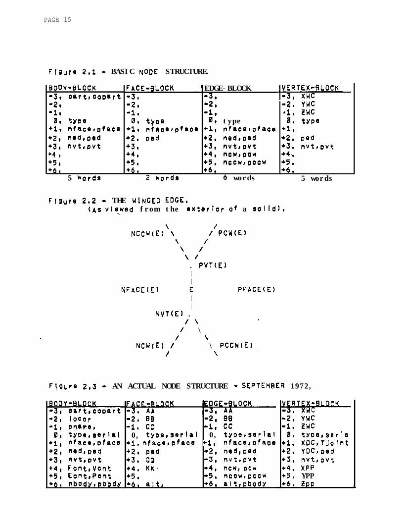
floure 2,l - BASIC NODE STRUCTURE.
E3OOY-BLOCK:lB bartrcomrt
-1:0, type
+l, nfacetpface+2, ned,ped+3, nvt,ovt+4 9+5r+fj,
5 words
EDGE-BLOCK-3,12,-1,0, type+L nfacemfaee+2, nedroad+3, nvt8ovt+4* ncw,oow+5, nccw~omw
42. YWC4. twc0. type
+l.+2. vd+3, nvtmft+43+5.
+6, 1+6,6 words 5 words
Figure 2e2 - THE WINGED EDGE,(A$ V;@Wed from the exterkr of a solIdI,-=.
\ /NCCWE)‘\ / PCW(E)
\ /\ /\ /. PVTE)II
NFACEK) E PfACE(E)II
NV(E) ./ 1 1
/ \/ \
NCW(E) / \ PCCWE) I/ \
vlure 283 - AN ACTUAL NODE STRUCTURE - W'TEWER 1972,
ODY BLOCK3, ;aft,coo8rt
m2r locar-1, mm!bp
lllr twmserlal+I, nfachpface+2, ned,ped+3, nvt,wt+4, Fcnt,Vcnt"5, Ecnt,Pmt
FACF Rl#K-3, iA-2, 88-1, cc -1, cc0, typemwlal 0, tymhsetfal
+i, nface,pfacO +l, nfacs,oface+2* pod +2, ned,md+3, QQ +3, nvt,pvt+4, KK- +4, ncb pew+5a +5@ ncowrfxcw+6, aIt, -+6, alt,Pbody
-2, YWC-1, ZWC0, tyPerserIa
+l. XOC,T.jofnt+2, YDCrmd+3. nvtmvt*4, XPP+5* YPP+6, i!DD

PAGE 16
I I , L kinged Eage 3ata Structure,
Mo~bsI Faces, Edges and Vertices are tepresenteo DJ blOCr(SO f contiguously aodressed Words, A singl8 block Size of Zen &WdS isadequate, A single tiord, like a LISP node, can 30ld t:io acfdresMs ofa floating POM number, The BFEV blocks aye Dointed 2; ey theaddress oi their word nmbered Zero Mich contains Control DiTslncicating whether the block Is a ii;:, Tace, Tdge or,vcrtex, Fhur?2.1 illustrates th2 block format IS being present@:! a s anexan,ole of a winsed edge data structure; a mlnima] numwr Of w o r d sfor each block is indicated.
T h e basic geometric datum is the vertex locals, &ich is3stored in three Words of each vertex block at positions -3, -ct -1;
these positlons are naqed XWCP YPJCI WC respectively: the l8tters'+!P stand&I fgr *'dorId coordinates",
The bash topological data are the three rims of the body;(a ring o f faces, a ring of ewes, and a ring of vertices) and thewinged edge pointers (eight such pointers In each edge blxk,and onesuch Polnt8r I n each face an3 vertex olock), The face, edge andvertex ring pointers at8 Stored a t positions +l, C, +3t eachPoSitiOrr has two names: NFACE, :4 E D ) NVT for the left pointersrespectively; and PFACE, qE[;, PVT for the right, A face, edge O rvertex can only belong to one body and so there is only 3ne bodY nodein a givsn face, edge or vertex ring: and that body node sWV8S a sthe head of the ring, The reason for double pointer rings is for thesake of rapld deletion; other minor advantages would not justify theuse of double rings,
The 8; ght WI?JSED pointers of an edge block include: twopointers to the faces of that edge, two pointers to the Vertic8S ofthat edge, and four pointers to the next edges clockwise and Counterc)OcWise in each of that edge's tdo faces; these last four pcintersar* called t h 6 wings of that edge, As figure 2.2 suggests, four ofthese eight Oolnters are stored in the same positions and referred toby' the sane naves as the face and vertex ring pointers; namely theNFACL, PFACE, NVT and PVT Oolnters, There are four ways in WI+3 aPair of f a c e s an3 a Oair of vertices can be placed Into the Wo faceDoSitiOnS and two Vertex posftlons of an edge; by constrajhing thesechoices tvJoPar itY#
bits are implIcitly encoded, one bit ist;;Al’d the Uc!eand the other Is called the surface CarftY; ohs are
exPlained later, Finally, the single winged edge pointer fmnd infaces and verttoes is kept in the position named PED and it ootnts toone of the edges belonging to that face or vertex.
Although the vertices in figure 2 . 2 ars shown with threeed3e% vertices nay havs anY number of edges; those Other 3tentialedges Would not !X ~11 tectly connected to E and so were not shop,
PAGE 17
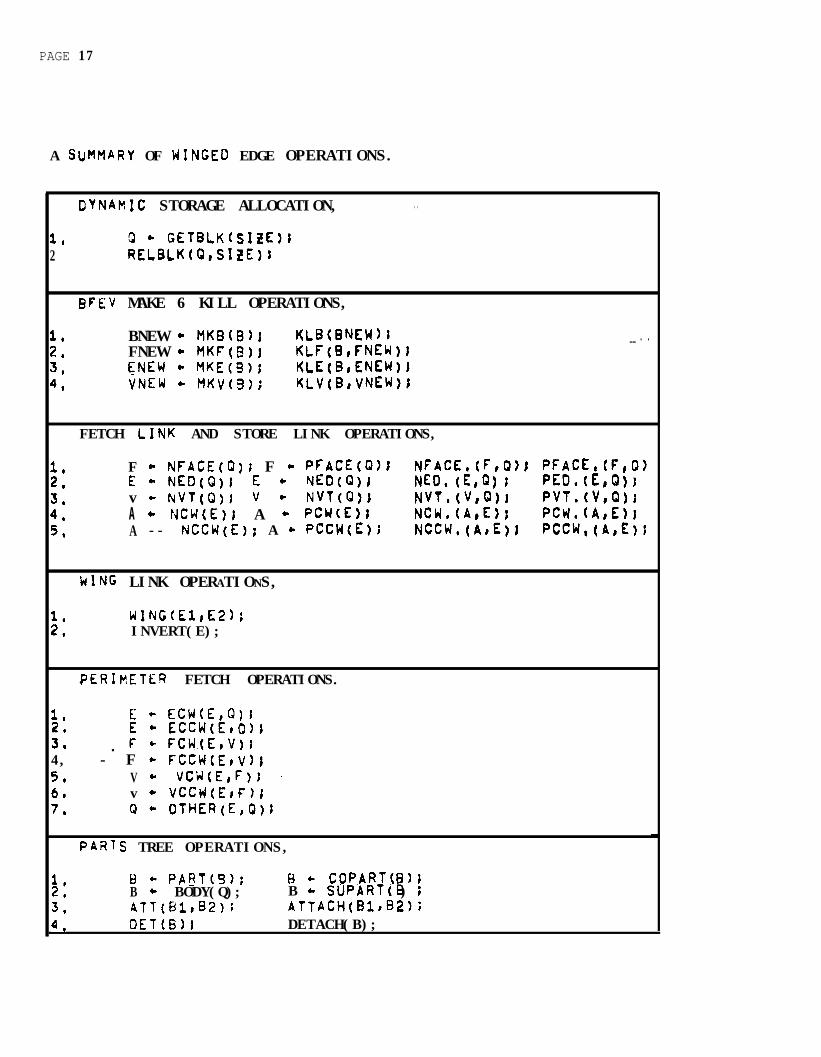
A SUMMARY OF WINGED EDGE OPERATIONS.
OYNAMIC STORAGE ALLOCATION, . .
1, Q * CEfBLKfSftE);2 RELBLK(Q,SItE)J
BFEV MAKE 6 KILL OPERATIONS,
1, BNEW - MKBU3); KLB(BNEW)r __ . .2. FNEW c MKFtEUr KLF(B,FNEW)I3. CNEW + YKE(5); KLE(B,ENEWI4. VNEW + MKV(B); KLV(B,VNEW
FETCH LINK AND STORE LINK OPERATIONS,
1. F c NFACE(Q)j F - PFACE(Q)t2, E- NED(Q)! E * NED(
NFACEdF,Q); $":;';;Q'NED. &Q) t ;
3, v - W/T(Q)1 V * NVT(Q): NVTd’,Q)r PVT:(V:Q)I4. A + NCW(E); A - PCW(E); NCW.(A,E): PCH.(A,E);5, A -- NCCW(E); A c PCCW{E); NCCW.(A&l PCCW,(A,E)f
)JING LINK OPERATIONS,
1. wING(El,E2);2, INVERT(E);
PERhETER FETCH OPERATIONS.
1. E + ECW(E,Q)r2. E* ECCW(E~C)I3. . F + FCW.(E,V)I4, - F * FCCWtEtV))5. V + vCW(E,F); -6. v - VCCWtEtF);7. Q - OTHER(E,Q);
PARIS TREE OPERATIONS,
1,2,3.4.
i-3 + PART(S); B ,- COPARTf );B + BODY(Q); B h I3SUPART( ) iATT(Bld32); ATTACH(BltB2);DET(BH DETACH(B);

Dynamic Storage Allocation,
At the Very bottoll, of whgt is beconIng ii rather deec rest o+prifritlveS within oriflitiVeSp are the two dYnamic storage aMclcationfunctions GETeLK anrj RELBLK. GETeLK allocates from 1 to di( wc?rdS; ofmemory Space in a contiguous block and returns the m&cWne &dress cfthe first word of that block, HELBLK releases the indicate? blccb tclthe availaole free memory space, (It 1s sad that the machines of ourday do not come Wit? dynamic free storage), A good reference foriml8fnW7ting Such dynamic storage, menti@r?ed earlier, is r(nuth[reference 73, Altmugh a fixed block size Of ten or f6har lkords capbe rade t o handle the 3FEV entities, grandiose and fickle researchapD)ications ( a s PJ~II a s memory use optimization) oeniirP theflexibility of a variable block size,
BFEV Make c( Kill Ooerstions.
Just above the f r e e s t o r a g e routir(es w e t h e four Dzirs o fmake and kill operations, The MK8 operation Creates 6 body 5lock. andattaches it as a sdb-part of the g i v e n body, The world F&y aNaysexists So that MKB(#IRLD) will make a body attached to the world, In.thiS bePer 1 the terms 'attach' and 'detach' refer to Op2ratiOR5 onthe Darts-tree linkages. The FEV make operations: MKL ::KE, PKVcreate the corresponding F E V eatities and place tile? iP theirresf?e&UVe FEV rings Of tha given body. In the current~mDlementation, th, FEV makers Set the tYPe b-its Of the entity, andincrement the proper total FEV counter, a~ Well as the ar3c*r bodyFEV counter in the given ~03~'s node, (the Fcnt, Gent, Vc~t nodeDoSitiOns are shown in figure 2,3), The kill operatfons: KLB, KU,KLL, and KLV; delete the entity from its ring (or remove It from theDarts-tree), release its SOaCe by ca! I lng RELBLK, and then decrementthe approrwlate counters, The body of the ent i ty i s peeded by t h e
'kill prfmitlves and can be provide directly as an argument or ifmissing, will oe found in the data by the primitive itself,
Fetch Link and Store Link OPerationS@
Each of the fetch link and Store link operations nz.nad in thesummary is a single machine instructton that accessas thecorresPondins link position in a node, Once EiFEV nodes c.xist, diththeir rings an3 Darts-tree already in place; the fetch a*d store Ilnkopera t ions are used to cons t ruc t or modify a p o l y h e d r o n ? L:L;rffce, Atthis lowest level, constructing a polyhedron requires Three stem:first t h e t w o Vertex a n d t w o f a c e p o i n t e r s &re claced i!:+,o each ecideIn counter clockwise Order as they appear when t/Tat edge is v i ewedf rOK the exterior of the Solid; second an edge pointer is oizced in9aCh face and vertex, so that one can later get from a g!vcn face Orvertex to one of its edges; and third the edge wings Fre Iinkeo sothat all the orderei aeiimeter accessing operations descrfbea belowwi II WCrk, t(jng linking is facilitated by the dING operaticn,

PAGE 19
I FIGliRf 2 . 4 - MIDPOINT EXAMPLE (gee text on page 20).
\ Pvt /\ / . .
ncow \ / POW\ I
v 0I
EhKw II nvt
VNEW .I pvt
ElI
Anew / \ pccw
I-. \/ nvt \
INTEGER PROCEDURE MIDPOIN'T (INTEGER EliBEGIN "MIDPOINT"
INTEGER B,ENEW,VNEWJ/ld2;
a CREATE A NEW EDGE AND VERTEXlB * BODY(E);VNEW * MKV(B))ENEW c MKE(B);
a GET VERTICES AND FACES CONNECTED TO EDGES;PVT,(PVt(E),ENEW);PVT,(VNEW,E);
e NVT,(VNEW,ENEW);PFACE,(PFACE(E),ENEW>;NFACE,(NFACE(E),ENEW);
a GET EDGES CONNECTED TO VERTICES;I IF PED(V)tE THEN PED,(ENEW,VbPEDJENEW,VNEW)I
a LINK THE WINGS TOGETHERIWING(NCCW(E>,ENEW);WING(PCW[E),ENEWliNCW,(E,ENEW);PCCW,(E,ENEW)IPCw,(ENEW,E,;NCCwdENEw,E,1
a PLACL VNEW AT MIDPOINT POSITION;Vl - PVT(ENEw)r V2 - NVT(E)iXWC(VNEW) + (xwc(vl)+xwc(v2)) * 0.5;YWCtVNEW) + (ys~c(v1~)+YWC(V2)) * 0.5:ZWC(VNEW) - (zwc(v1)+twCfV2)) 0 0,5;RETURN(VNEW)r
FND “MInPOINf”:

PAGE 20
The W'ing Link Operation,
The WING operation stores edge pointers into edges so thatthe face perimeters and vertex perinetefs are made; and SO thatsurface pvlty is p r e s e r v e d , Given two edses which have a vertex and8 face in common, the WING operat-ion places t h e first edSe In thePrOpV relationship (PC% NCCWI NCW, or PCCY) with reszect to thesecond, and the second in the proper relationship with respect to thefirst, The INVERT operation swaps the vertex, face, clockwise wing,and counter clockwise wing pointers of an edge. IWEPT creservessurface parltY, but flips edge parity.
The Midpoint Examale,
In figure 2.4 an example of how the ODeratiOns given SO farcoula be used to code a midpoint primitive is shown, The examolemiapoint prlmitive takes an edge argument and splits it in two bYmaking a new edge and a new vertex and by placing thm Into theool>hearon with the topology shown In the diagram, Then the midpoIntlocus 1s computid and the new vertex is retWn, The ALCOL notationus*a 1s SAILI which a)lows defining the character "a" as a 53MfiENTdelimiter and allows deffnlng XWC as a real number from the spectalarray named MEMORY, The MEMORY a r r a y fn SAIL Is the job's actualmachlne memory space and gives the user the freedom of accessing anywore in his core image,
The Parts-Tree Operations.
AS shown In figure 2,1r each body node has t'do Darts-treelinks named PART and COPART, The PART link is the head of ZI liS% O fsub-parts of the body, When a body has no sub-parts the PAGT link isthe negative of that body's polnteri that is the body DOintS a*,itself, When a body has parts, the first part is pointed at 5~ PARTano the second 1s pointed at by the CCPART I ink of the first and so
- on until a negative pointer Is retrieved which inaicates the end ofthe parts list, The negative pointer at the end of a oarts I istPoints back to the orginal body, which is the supra-part or "supart"of all those bodies in that list,
The parts may be accessed by its llnk names PART and COPART,Also the SUpART of a body returns the (positive) pointer to thesupart of a body, The BODY operation returns the body to which a faceedge Or Vertex belongs: this might be found by CnR'ing a FEV ringunti I a body node is reached, but for the sake of speed each edge (asshOwn in figure 2,3) has a PBOOY Iink which points back to the b o d yto which the edge belongs, and since each face and vertex points atan edge, the body of an FEV entity can be retrieved by Ce+,chihg onlyone or two Ilnks,

PAGE 21
P a r t Tree Operation3 (continue-%
The parts-tree 1s altered b y the DET(W 0peratIcn WhiChreffoves a body [j from Its supart and leaves It hanging free; ?rrr3 theATTWl~B2) operation which places a free body Pl Into the parts Ifstof a b o d y 82, since bodies are nade attached to the ~rlc? bcdy anrjgenerally kept attached to something, two further p?rts-treeoperations ate proviCh& compounding the first two in ths necessarymarnet, The DETACH(B) operation DET's B from Its current 0b'nB r andATT'S it to the world; and the ATTACH(Bl,@) operation: ~!f I I LET Elfrorr its supart and attach it to a new supart. In ncrnai (one world)circumstances one Only neecjs t0 Us2 ATTACH to build thin?S,
Perimeter Fetch and Store Operations,
There are seven perimeter fetch pr??itiVes, whict khan Givenan edYe an3 One of i t 3 links wiI I fetch another link in G cert-,ainfashion, Using t-he winged edYe data Structure these prinit;ves 3reeasily implemented in a few machine instructions which test the tb'pebits ano tYpically do one or two cornDares, Clockwise a. n d counterclocbdge are alwaYs determined fr@n the outside of a p':I~+edronlooKin down on a part!cular face, edge or vertex, I ar0log;zz f-Ofttie hich redundancy on the next paso, but felt that it "a5 v?zessaryto rake the explsna$onS independent for reference,
FIGLhE 2,' - Face Perimeter AccessinC! witn respect to eo?e E,

The Perimeter Fetch Operations@
E t LcW(E,F); Get Edge Clockwise from E about F's Deri~eter.f + LCC;W&F); Get Edge Counter Clockwise from E about F's b?rimetar,
*Given an 8dg8 an0 a face belonging t0 that edge, thg ECWfetch primltivrs returns the next edge clockwisa belangh to thegiven face's perimeter and the ECCW fetch primitive returns tha nextedge counter ClOckwfse belonging to 'the given face's oerl;nster,
i + tsWE,V); Get Edge Clockwise from E about V's perimeter,Et LCCk(E,V); Got Edge Counter clockwise from c about V's oerl;Jater.
Given an edge and a vertex belonging to that edge, t5a zcwfetch primltiva returns the next edge clockwIse belomlng to thegiven vertex's perimeter and the ECCW fetch primitive returV thenext edge counter clockwise belonging to tne give:! Vert8x'sperimeter. --_
f + FCk(E,V)j Get the face clockwise from E about V*F c uxwCE,v); Get the face counter clockwise from E about VI
Given a II edge and a v e r t e x b e l o n g i n g t o t h a t edge, the FCWfetch orimltlva returns the face clockwise from the given edge aboutth8 given vertex and the FCCW fetch primitive returns the facecounter ctockwlse from the given edge about the given V8rtax.
V c VCW(E,FI; Get the vertex clockwise from E about F,V t VCCW(E,FI; Get the vertex counter Clockwise from E about F,
Given an edge and a face be longing to that edae, the VCWfetch Primitive returns the vertex ClOckWise from the given edgeabout the given face and the VCCW fetch primitive returns the vertex
a counter c(ockw!se from the given edge about the given face,
F t OTQR(L,F); Get the other face of an edge,v * UTHER(E,V); Get the other vertex of an edge.
.
Given a9 edge and one face of thatee;e the CTHEF fetcharhithe returns th8 other face belonglng to edgo. Gtven a nedge and one vertex of that edge the OTHER fetch Orinitfvs returnsthe other vertex be(onglng to that edge,


PAGE 24
II, L ElaDorations (Jo Winsed Edge StrUCtUrg*
I? tcIts sw2ion, some var iat i o n s on the b~.:.s i c w i n(JeCiedG6 s t r u c t u r e at3 g i v e n , Theso variations ati:e as adTbta:;:nc ForrY aWlicatlon, anj as UQiWl8m@-nt8d ideas for j?l?roven?nts, TfiFadqztations, Shown in fiSIJr8 2.3, include adding serial namers ant’AL’T I inks to al I the faCRs, edges a n d v e r t i c e s , T n e si?rial *‘;T.t?erscrcvhe a n o t h e r day cf addressing an0 ar8 especiallq usefc I tLjr I nr:ir;h,t am o u t p u t , The ALT link is used for pointing to a!c’ftiowl PutteT$PrarY data; tW most elaborat8 ALT d a t a has to ao Kit,h 0 (1 1 8 s..
during a hidden Iiqe elMnation, Sacrificing mezo;y spzce for f;~)ee~and fi8xibility, the fac9 ar7d edge coefficients are store7 ir? GlChnoa&, aM th8 h2Qe coordinat8 (X~p,Yop,&m) ant1 dicgiay :ocr?inzt.es(Xacddc) are ached to each vertex, In alaSorate Systems, + ‘m ,- i K,aSPCoOpJinates mOG81 a caqerii and the display coorain;tF; ‘Fef~r toIGCatiOr o n a sis;?lAy console. tiaviqg two tiers Gf i ftlT~;c!Co0rSna+es al lo+ 3~: oiling about t h e mQda/ea haige witra,t cr-,arl~trn:;tt-+ Careta (Or heaven fcrbidder, maving t o red0 a 7iq:ec I inaelkrination;, --_ Tha retaining S O far WVI’I8n?iOned nanes ;r,cIu:!a: c, P .?Tjoirt I in% in vertlcas dhicn ic: for shad04 F. I-! a /T 1 z.“e- 1 iflooprations, tha tre 23 tior(j in fdces w h i c h contains ghOt:Jry+-tri? data,znd tne l3Xl3 a.nc pr;&:-!c 1 inks of a boay nobe, .dhich p’;ll d* *t to aloCati0r-oriantat;on c;atrix and an ASCII print n3.W resg2c:;t,3/&‘,
SacrlfWnQ speed for the sake of ve7ory, ‘;ne e f f e c t Gfhaving mst of the extra d;1ta mentioned above Cal be 3c.n i evZ:l t:\.reccPputinS it rather than fetching it, Furtherr?ore, the diflGc:J t.athstricture c a n be rta$e slightly sPal/Qr b y @l%natinC t P g 4I ar,e andv e r t e x rings, Face ~7~1 vertex sequential accessIn can 5;: i I ,7e dcq-?by riving ~NO ryark ins oits i n e a c h f a c e ,and vertsx,atuz! tq’ ;Wtl ‘:I3 I :I?tori t h e edqo rir,q lookiqa a t t h e ti-‘o fqces a n d tdo vertices ?:f each~d?e for on6s t h a t a r e qot frsshly larked, It wo\Jld be nit? if suck
8cOrCniZin3 could be done 9elw the level of the ooerat;an5,
FcesiUes OptiFiZatioQsr th8 next i7proveWmt idea I ~cu(if Iikt?t0 attmct Hould be to sr?lit tne notion of R bO3Y i ntc the twonotions of a “part” and a Vel I”, parts WOlJld h a v e t*e 03rtS treeanc n a m e s tnat b o d i e s nod have, whereas a cell ‘+!o:~Id have vOIu’c? andf@-C6 structure, In th;s hypothetical Cell, Face, Edge, ‘?er+,ax CCFCV)m&&l, each face coi~tc point tc a ee,ll on either side of it, ‘;“Q czl I
witi tt?o lower serial qj”ber ( o r S@?l8tt’il73) beirg Cz73:rUw 2::0xteriOr, Cell ntiF3er Zero wou(d h8 t3e i n f i n i t e void 0; +,kree 5L7ac7in which everYt+rc: is sinbedded, The trOJblo ‘di-i;h CFE,;,’ :s that thyipocrtay?t matter of 2 Do)yhedron surface ‘las to be salvaleo; it cannot be ak~andonec!, Czcausa mocle I s w 1 thout good surf~e rerreszntat i cnccan not predict <3oc8zr2nc8, which is one of my requireme?:?,
PAGE 25
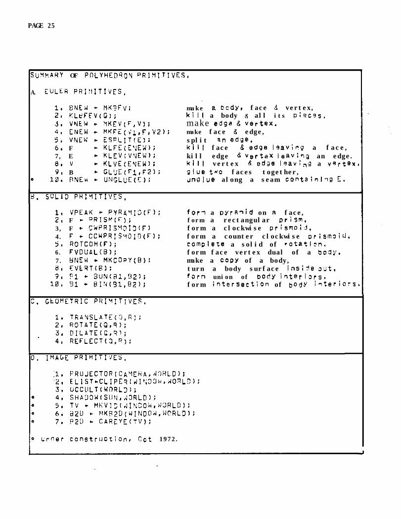
SuWN?Y OF PnLYHEnRg?J PRI?lITIVES,
A. EULkR PRI"lITIVES,
4
1, ENEN .= ?lK?FV;21 KLtsFFVcQ>;3. VNLW + tiKEV(F,V);4, CNEW e= MKFZ(vQ,F,V2):5. VNEW + ESFLIT<E>;6. F + KLFE(E'JEX);7, E + KLEVcVyEW);0, v + KLvE(EYEW);9, B * GL'JE(Fl,F2);
10. PNEti + UNGLUE(IT)i
. .make 2 body, face d vertex,kill a body K all its phcss,make edge 8 vertex,make face 8 edge,split qn edge,kill face 8 edge Isavhq a face,kill edge C: VertaX leavhg an edge.kill vertex 8 edge leaving a vertex,glue tdo faces together,crn9lue along a seam containlrg E.
.6 SOLID PHIMITIVES,
1, VPEAK + PvRAY:3(F);2, F + PRISWF).;3, F + OW?I~M~I~(F)4. F + CCWPR:SyOI3(F);5, ROTCOM(F);6. FVDUAL(B>;7. UN% c MKCDpY(R);0, EVLYT(B);9, PI * 3UN(X,!32);
10, 51, - BI!d(91,82);
for7 a oyraqid on a face,form a rectangular prism,form a clockwise prismo;A,form a counter clockwise orjsmoid,complete a solid of rotathn,form face vertex dual of a bog?/,make a COPY of a body,turn a body surface Inside wt,fern union of boc!y irlteriors,form intersection of bOrjY titeriots.
I -1, TRA%LATE(O,R);2, ROTATE(3, @ILATE(e4, REFLECT(&R):
ck IMAGE PRIMIU'JES,
I * I;f,fler constfUCtiOnr act 1972.

PAGE 26
I I I , PhIPITIVES ON POLYHEaRA,
In this section a number of orimitbes for doirl% thin’;s t opobhedra are exolained, Although these arilnitives yre currentlyimPlemented using the winged edge data strUctur8, they do not raaulrea particular PolYhedron representation, Indeed, many of theseo&r.Wves Were 0rigfnallY implemented in
Pal:,LEAP o31Yhedron
representation Very similar t o that of FeldTan ald P a u lCreference 53, ThU3, the primftives of this section are on a I eve Ilo9iCally independent from the operations of the previous sect;on,
Another asoect of these primitives is Oat tney :a? be usedas th8 basis of a "9raph i cs language” or nom accurately as a gacka3eof subroutines for ;leometric modeling In this vein, the gri7itivesare currently collected as a cackage ial l e d GE%iES for S80flQtricModeling Embedded iq SAIL; and as GEOMEL, Geometric Modelirg Embeddedin LISP, A Wrd language, called CEOMED, arises out of t%e commandlangua9e of a Y8Ometric model edftor based on the primitives,
-=.The primitives ar9 shown in four groups in the slJm"rary, The
first 9roWb the Euler ?rimitiMs, were Inspired 5y Coxejter’cj vaofof Euler's formUla, section 10.3 of [reference 25. Althoug- :ne Proofonly teouired three prlmitivesl addkional Ones of the sa,"e i!k Yers
develoOed for convenhpce, The second group is compose 3 of somepolyhedron primitivgs that were coded using the Euler brimftives. Thethir0 group Is for orfmitives that move bodies, faces, sclgC?s andvertices; or c0mnute geometric values such as length and V~NRP, ThisBrOUP 1s underdeveloned for two reasons: one, because ! have donethese computations a d hoc to date; and two, because the;l Irxly thesubject of animation which 1s large snd difficult 2nd not c?f ‘38ntralhoortance t o Vision, With the eXc8pthn of the c2m8ra0 7y ~crlds 2renearly (but not absolutelYI statlc, A less imDov8r ishad ,jeoCletr icarOUD hill b e presented in the future, The final group, has threeWeJ 1 deve I oped DrinitlV8S for making 2 0 images; an3 several
- prirdtlvas that when finished will realize Part OF the vis;on s}'zter"that I am trying to bull&

PAGE 27
411, Ac Euler Prirnitlves~
As mention above, the Euler p~lmltlves are based on the EulerEquation F%+V 5 2+Ba24‘HJ where Fe E, V, B and H stand I'& the numberof fhces, edo;es, Vert!cesr bodies and hundlas that exist, The term"handle" comes from topoloW8 and Is the number of well formed holesfn a surface; a sphere has no handles+ a torus has one handle, and anIBM flowchartha template has 26 h a n d l e s , The Euler eauatlonrestr lots the posstble topologies .of FEV graphs that can bePoltihedra; a l t h o u g h s u c h Eulerian P o l y h e d r a d o n o t necessarflucorresDond to what we normally oall a solid classical aolyhedron.Strict adherence to constructing a polyhedron that satisfies Eulerequation F-E+V = 2*3 - 2*H Would require only four primitives:
+F -E +V = 2*B - 2W
la Make Body, Face and Vertex +l . . ..+l.l.*+l...o.2, Make Edge--.and Vertex, ,.,-1 +l ,rrr~*~*rl,(3, Make Face and Edge, +l -1 rroerr*(ce~*r(r4, Clue two faces of one body, -2 +N -N ,..*..,.,.+l4.' Glue two faces of two bodies. -2 +N -N,.rr~l,,,r,r
However, the four correspondfns destructive OrimltlVes are alsopossible and desirable:
+F -E +V = 2wB - 2+H
1, KI I I Body, Face and Vertex -1. -l,r,.-l,rtr*.* e * 029 Kill Edge and Vertex. ,..+l -1 **,*,*#*@*t@3, Kil I Face and Edge, -1 +l ,**,r,*r*e*r*tc4, Unglue along a seam. +2 -N +N ,,,.,..*..-14,' UnSlue along a seam* -2 +N -N,,r.+l, * e *,*
And finally the ODeratIon of solltting an edge at a flidpoiflt into twoe&es oecame s o important In formhe T-joints dur inQ hidden I tneelifrination t h a t tee ~sfq.11 p r i m i t i v e w a s I n t r o d u c e d in PiaCe of theequivalent KLFE, #EV, MKFE secwn~b
In ustngare tolerated as
the Euler prIj5ltit;;s,transitional
som;h;On-ciass;cal DoJyhedraof ConstructIoni these
transitional states are cal led:
Seminal Polyhedron,Mire PolYhedron,Lamlna PolYhedronqShell Polyhedron,F a c e wftn bJ:re SpUrS on It5 Wrimetet.
A sgrinal polyhedron is like a point; a Nire polyhedron is I inearwith two ends Ilke a single piece Of Wirei lamfna and shell Polyhedraare surfaces, and the p;cfuresaue phrase about ScNrs is a r e s t r i c t i o non how faces are dissected Into more faces, These te;ms I*riII beexGJainec! ia more dgtalj when they are n e e d e d ,

IPAGE 28 j
I I I , Ar Euler bhitivesc
1 , tiv\rEw * MKBFV: Make Seminal E?ody.
The MYWV o&nitIve @turns a body with one face md onevertex and no edges, Other bodies are formed by aodyh2 oriTitiVC3st0 the semhal MKBFV body, The seminal body 1s initially attached asa Part of the world,
r 2, kLBFEV(t3NEW); Kill Body end all its olecesv
The KLEFEV primitive will detach and ddlate frm memory thebody given as an ar;u;;rent as wei 1 as all its faces, f?dp?S, varticesma sue-parts.
3, PEW 6 MKEV(F,V); M a k e en edge and a vertex.
T h e MKCV primitive takes a f a c e , F, a n d a v e r t e x , V, of F'sDer ireter and it creates a new edge, ENEY, and a new vertexI VNEW.Et\lE)u and VNEW aYe ca\ led a “Wire spur" at V on F, iIKE\/ r9turnS theneh I Y trade vertex, VNEW; E Iv E 14 can be reached since PEDW~bU is
aPaYs ENEW, Only one wit8 Spur Is allowed at V on F at a time,
When applied to the face of a seminal body, MKE'J forw thespecial p o l y h e d r o n cal led a "wire" and returns the new vertex as the"negat i vet1 end of the wire A wire DoMedron is illustrated infigure 3.1, When aDPIled io the negative end of a wire, MKEV extendsthe kirer however if applied to any other vertax of the w/r% MKEVrefuses to change anything and merely returns its vertex atrjument,
Figure 5.1 - k Cre Polyhedron, Figure 3.2 - vNE!;c 'WZV(F,V);
seminal vertex @ ViPositive en3 +I of wire.
! El-IQ v2
+II E2
negative end -I cf wirerlatest vertex 6 \I3

PAGE 29
b VA&E A CUBE;~JTEC;LH PROCEDURE MKC;IaE; . .3EGIk "b!hCUi?E"
INTEGER B,F,E,'&VZ,V3rV4;8 &LATE SEMINAL POLYHEDRON;
b 6 r?KE?FV; F .- PFACt(B); VI * PVTfS);xwc(vlb+l: YiJc(vlb+l; i!WC(VlP-11
1 yA(L SEMIN&L POLYHEDRON IYTO A LAMfNA PQLYhEDR(%b2 - MKEV(F,V1); XWC(V2b-1;v3 + MKEV(F,Q); YWC(V3)-1:v4 + MKEV(F,V3); XWC(V4)*+liF + fYUE(V1,F#V4b
3 MAKt: FOUR SPURS ox TtiE LAMIFJA;Vl - r?KEV(F,V1); tdC(Vi)*+liv 2 t MKEV(F,V2,;V3 t MKEVcF.,V~);v4 - MKEV(F,V4):
z ~ijInl SWJHS TO FCR,r FI%AL FAC E S ;E + MKFL(Vl,r,Vi?);E - MKFE(V2,FtVS)iE + MKFE(V&F,W);E t MKFE(V4,FdlkkET!JWiW);
CND "MKCUBE";
x FCWI A PYRAMIL~ ON A F AC E ;
1PAGE 30
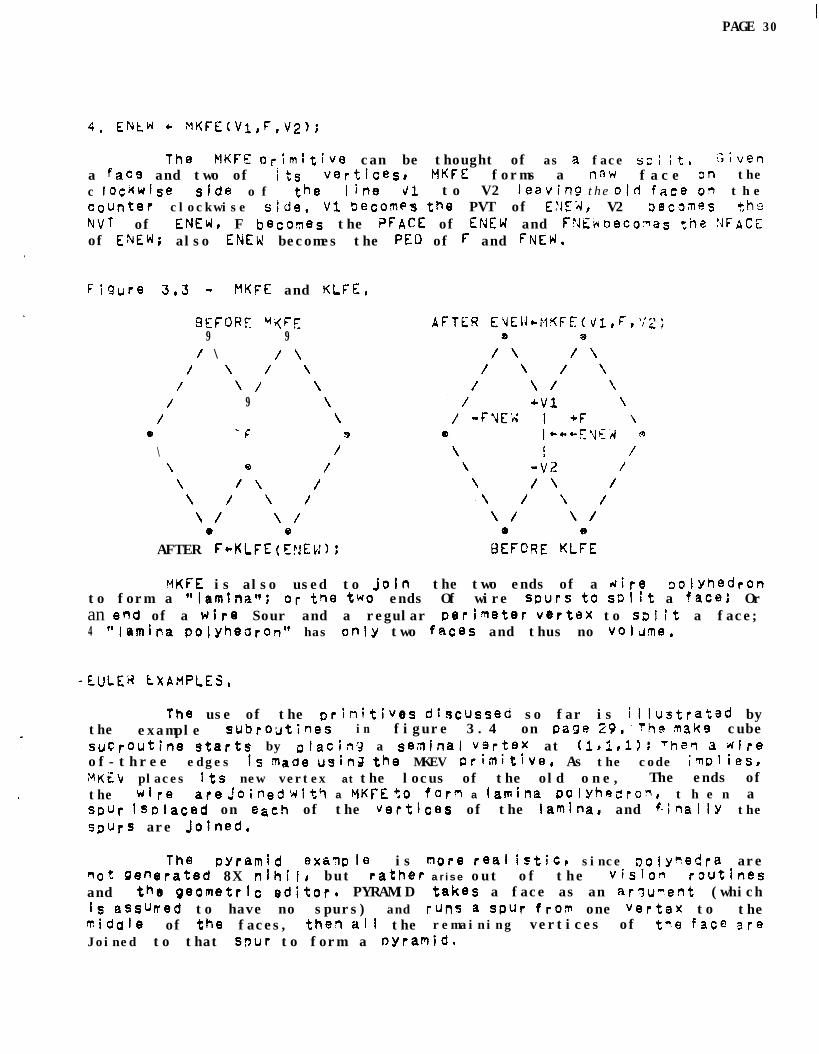
4. ENtW * nKFE(Vl,F,V2);
.
The MKFE P,-irnltive can be thought of as a face 53; it, GbfC?n
a fac9 and two of f ts vetticesI MKFE forms a naw face 3n thec tockwJse s1d8 o f the ih8 41. to V2 l8aviW t h e o/d face 03 t h ecounter clockwise side, V1 Becomes th8 PVT of E:rE;1, V2 il8c0~eS t,h@NVT of WE% F becoqes the ?FACE of ENEW and FFJW beco~as the REFACEof ENEW; also ENEW becomes the PEO of F and FNEW,
figure 3.3 - MKFE and KLFE,
BEFORE W(FF:9 9
/ \ / \/ \ / \
/ \ / \/ 9 \
/ \0 -=_ mP ,\ I9\ 9 /
\ I\ I
\ / \ /
\ / \ /e 9
AFTER FcKLFE(EyEti):
tiKFE is also used to join the two ends of a Hire oolynedronto form a @tlamlna@? Or the two ends Of wire Spurs t0 SDl!t a face; Oran end of a wire Sour and a regular Derim8t8r vertex to ssJ;t a face;4 "tarnina pOjyh8drOn" has only two fRc8s and thus no vol~ms,
The use of the Drinitives dkscuss8d so far is illustrated bythe example subroutines in figure 3.4 on page 29,'rhe mke cubesUCroUtin8 starts by placing a s%rlinal vgrt8x at (l,i,l): Theq a direof-three edges is made Using the MKEV wimitive, As the code iInplies,MKEL places Jts new vertex at the locus of the old one, The ends ofthe wire are joined wit9 a WKFE +,o form a iamina POlYhQdro~, t h e n aspur iS placed on each of the Vertices of the lanina, and f-inallY theSpurs are Jolned,
The pyramid exmg I8 is more real istiC, since ~Ojy%c!ra aremot generated 8X nihilr but rather arise out of the vision roUtin8sand th8 g8Ometric editor. PYRAMID takes a face as an arqur?ent (whichis assured to have no spurs) and runs a spur frop one vertex to theTidal8 of the faces, th8q all the remaining vertices of the face areJoined to that spur to form a oyramid.

PAGE 31

PAGE 3I
5. ~h~bi e EWLXT(C); E3sg Si;l it,
Th i s primitive Solits an edge by r&kiW a new vertex ar,d aned edge, Its Imolenentazion is v e r y s i m i l a r to ttie r7iODci*t, f?XWh-leo n cage 19, FSPLIT ;S tleqvily cased in the Chidden line elir:rnztar,
6. F - 6LFUESEU; K i I I Face FIqge,
Tf?is prtfniti v g Kills a face 2nd an e d g e leaving c7e face.Sir@ t h i s grtmit,ivz 1s iftended t;o be an inverse of PI!KFE, the hiFAXo f ~rdpi is Ki1lf33, +o*ever ttie NFAX and PFACE of :I n edse lay beSk? frsed by using the !‘\JVF?T(E) p,rimitiQ?, See Figilrg 3,s icr CFE,
Tnis PrjaTitivg kills an e3;e and a vgrt9x lezivinr: are ec;~~s IThis CrimitiVe NilI s;Ilinat-z spurs Tack With rv1fiFiJ ard 17;G::3intS ;7adeWitP LSpI.!T; i’n’ 2 CJre for? It LJOUIC hhvB to leave vert&s iit,!7 pVa I em9 g r e a t e r f,nan t w o Jnt,oL;ched, h o w e v e r it In fact “u?-~lyraViilsl’tne7 with a sgrlgs of 5LF E’s and then kills the remaini’n.4 FDbr,
e, v + KLVtdEYE’d); Ki I I V!qtex Edge,
This prlqitive kills a vertex and an edge IezvinLq qn-3 vertex.T h i s prinitlve 1s t?;~! face-vertex dual of KLFE p narlely i nctestti ofki 1 I inS xFacE o f E and f i x i n g up PFASE’s Derinatert KLE’i/ kills theYVT cf E and fixes UC V’T of E’s per imatgr.
9. b + GLuE(FlrK?)~ c;iI.ro two faces.
This primitive ::Iues two faces t o g e t h e r f;rFinS one x2 Sodya gtJt of txo old ongs (:ng body of F: survivgs) or forFir; a handle o n
tne given oody, T4e ng”lbey O f OdY9s In tne two faces must L?e tt:e s3means tqeir orientation shodid be opposite (exterior to gxterior!,
Tn i s p r i m i t i v e imiws a I onE the Sea77 contair?iqg E, Theur\;gLu~ orimitivg reoJirgs that a IOOP @f eaggs 20 .yarked a.5 2 9’ s e a 17 tqalor hhic$ unglue Will for’7 two opoosfte faces, The 53rrs are mnadein the te m p o r a r y tyog bit, in the edge node, Of the pivm bcdi, Ifthe c u t forms LWO tiisj19int jodies thgrl a ngti ooay is -a29 On thgNF4CL sida of the’orig;nal E argWng0t.

PAGE 33
III, 8, SOLID PRIMIT!VES,
1, LPEAK + PYRAMID(F);2. F - PRISNF);3, F c C~PRISMIOD(F)t4, F + CCWPRISMIOD(F);
These four ptimitives are cal l e d th8 "sweep ~rfritives",because they form a simple polyhedron from a face in a fashion thatapmars I Ike sweeping the face along, The sweep primitives (with theexcePtion of PYRAMIZ) do not change the locatton of the ~i;ven f a c ebut meye ly COPY its petim@JtfV, forming new f a c e s and edges befwaenthe O/d perimeter and the new Derimeter, The pyramid prim;tiVe hasalready appeared as an e x a m p l e on pas8 2 9 .
Starting with a nine sided face lamina, the rocket ;n figure3,6 was formed from the bottom by sueeolng two prism stases, then twocounter clOckwfs8 o-tfsmoid sta9esr and then two clockwise Drismoids t a g e s 8 and finally one pyramfcj to form the nose cone, the f;rs vJeremade bY prism sweeping everyth~rd face of the first stage,
FIGWE 3.6 - Rockets made with sweep primitives.

PAGE 34
III, tjm SOLID PRIMITIVES, (Continued).
5, RW~OM(F)t Rotation Completion,
As IiiUstrated in the first thr88 frames of f&lure 3.7 oe/ow,wire faces oan be swept to form a--shell, When a wire face 1s swept bya SW-P prfmltlve (other than oyralnid) it 1s marked as a shell faceof rotation and Its original petfmeter count Is kept for later sweepsto refer to, In the third frame the shell has been oositioned sothat its slot can be seen, T h e she1 I f a c e now includss all t4e edsesof both Pole caos as well as the two meridtans of the slot, ROTCOMtakes Such a shell face and breaks it into Wo Do lar f a c e s ano asrany other faces as necessary, by means of tne count that wa3 savecl,
FIGURE 3.7 - Solid formed by rotation.

PAGE 35
Euclid's construction of a dodecahedron from a cube.
FIGLXE 3.8 - Dual of a Dodecahedron.
PAGE 36 1
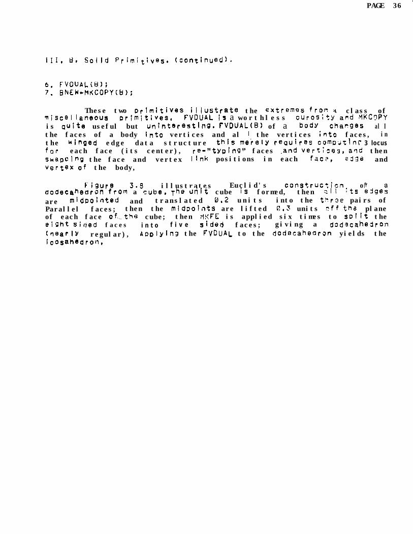
III, 8. SolId Primit!ves, (continued).
6. F-VDUALN);7. GkEN+MfiCOPY(B);
These two primitives iliustrate the extremes fron 4 class ofTiScel laneous Primitives, FVDUAL is a worthless c~tos~ty acd MKC3PYis Quite useful but unlntereating. TWUAL(B) of a body chames al Ithe faces of a body Into vertices and al 1 the vertices ;nto faces, inthe winged edge data structure this meiely racjuires comwt\nc 3 locusfor each face (its center), re-"typing" faces land vertkss, arid thenshepoing the face and vertex Ilnk positions in each farx, ed3a andvertex of the body,
FiWre 3.5 illustrates Euclid's constrUc:icn ofdodeCahedrOn from a cube, The unft cube is formed, then :II its edge:are midpointed and translated g.2 units into the WrSe pairs ofParallel faces; then the midDoifits are lifted G1,3 units r?ff tha planeof each face of=.the cube; then ,wFE is applied six times to spllt theeXht sided faces i n t o f i v e sided faces; giving a dgdscahedron(near IY regular), Aoplylna the FVGUAL to the dodecabdrm yields theicosahedron,

PAGE 38 I'.
These thr3e Dri?lftiVZs -.Oerform the ic9olaap rqxratiow 09OOlyhedrcln int e r i o r vOluws. E;/ERT(B) turns i; body insiCe out, thuschar?(ling a cube into a room, as a solid into a bubole, Ct jeCts Hi thinfinite “inter iOrS** are psrmissltlei such polyhedra are impossiblein rany classical developemants o f solid Geometry A5iOh make t h ei n t e r i o r o f a OOlyhectran to be the region of space wit? finitevcIu~et b y definition, The body union is PUN, which al 13~s 61 t os u r v i v e i f t h e Interiors of tha tof?ies are not d i s j o i n t , A boay 4tt1two disjoiot DolYh2~rons Is shunned, The boay intersectjon is S!V,;Ybich allows I31 to survive if thedisjoint,
--.
TWO BODIES
BODY INTERSECTION
of tes bo.$;es d?3 not
BODY TJNION
BODY SUBTRACTION
FIGURE 3.9

PAGE 39
L GLOMETRIC PRIMITIVES,
1, TRANSLATEN,!?): Q argument is a body, face, edge or vertex+2, RUTATE(Q,R); q argument i--S a transformation array with3 , DILATE( respect to world coordinates,4. RLFLECT(Q,R);
The four EUclidean transforrations are translation, rotation,reflection and dl latloni a n d a s f i r s t mention8d in Kle!n's EriangenProG'a% 1872, these four OrimhiveS form a 9roUP, Th8 PriT!tives maybe a p p l i e d t o bodies, faces, edges or vertices in order to changevertex hOrId locii, Thus a body 1s the set of vert/oes ;r~ its vertexrinS0 a face Is the set of vertices on its Derfmeter, an sdge is thetwo vertices Which are its ends,.and a single vertex is itselfi butthe+ are special c a s e s having to d o with faces; (In GEOMEiI aspeciaf c o u n t e r , negative Fcnt, is maintained in wire sweet faces inorder to make solids of rotaticn). The second arWm8nt R Is a Pointerto a t ransformation array In world coordinates of four rows and threecoluwts:
xwc, YW, zk'cIX, IY, Ii!JX, JY, JtKX, KY, Kt
For trarslation, only the XXC, Y:K and ZWC are involved a n d all t 17 evertices ara translated in the obvious fashion:
x - x + xx; Y c Y + ywc; z * z + zwc;
AhepaS for rotaCon (31 lation and r0flWtion) the tnnermostCorDutatiori apcAied to earn vertex is:
X + x + Xbp-iI: Y + Y + YWC; t 6 3 + zwc;mxx + IWX + Iy*Y + It&i;YY - JX*X + JY*Y + Jt*S; .G! + K!(q + Ky*v -+. t'\t+Z;x +xX-XbG Y*YY-YkCi z*r;!-it)Jci
At th’is point,1 should now present a few genera I Primtt1ves forsetting up Such transformation arrays, but I don't have them yat, TheSyOb l8fl iWolves selectin frames O f refer@nces, s t r e n g t h O ftrar3fOrf7atlon, aXgs Of transfornations, origins of fraqes and modessuch a s abSOiUt3, relative o r intemolated, A t firesent in m yapulkations t h e s e matterS art3 handled a d hoc (the mast generalsOlutiOc beins the ?L7TkEL aqd EUCLI@ subroutines of SESMED), T h eheart c f derivin3 a trawformation array is to gat a f r a m e o freference ;:Ef ant a7 amount of rotatlo7l DEL and to compute the rclatrix
R + (tra~s~o~e(REF)cross(DEL CROSS FIEF)):
F 42 f db;ction (larger or smaller) Cross DEL di’;n a non-ueity diagonalTaTrix; for t3fleOtionS flip the rob! Sig7S on desired axes,

PAGE 40
* urdet ConstrtiCtiOn, @et 1972,
HWJECTOR comogtes tpe persoectjve p r o j e c t e d 10~s 2F III thebertices in a Given world from a given cmefa, CLIPER wxilt3s yywD0ftions O f 3D lines thn? are visible within a given d;s~]ay dir\dcW.OCC< ccm;)ares all the +Qes, faces and vertices in a :! i v i! ? war Id;us i cli their current proJecterj coordlnatest faces, eagas and vsftkasthat are not VSsijle from the i m p l i e d c a m e r a ’ s vi8vJsoint zre marked
as bidder?; f a C.8 3 # edges a n d vertices that ar? visinle (7r(:! ?afKed a svisible; and faces, edges ano vertices that Were initial ly martiallyvisible afQ broken up into vistble a n d h i d d e n pottiocls. Me newfaC8Sp edges and vertices introduced by XCULT ‘-: r e n?.‘.tkb;j SO t h a tthey can be removed,
Ths followky four Dfimitives a r e sti I I be i qq davelacmd,Sl-iAGULl will literally build a w o r l d w i t n shadows it1 it; shadow calls3CCL;CT tw 1 C8, once for the SclN and once for the camera, There Is noc o n c e p t u a l difficulty in d o i n g m a n y Doi!lt sotirces, but I shall getone SOUfc8 warkIng at a time, The ?lKVIC) Dri?i+,;ve J8rerat0S T Vintensity f a s t e r 5 f r o m the world model after OCCULT or SYA30W hasb88n aPplied, T h e WQ25 primitfve generates a 20 data structiire ofreQiOns and edges (which is almost a COPY of the 30 strtrcture thgthas been pt8S8nt8cjr r?ut with SD8Cial attention paid t o T-joints);this QC data StftJcture is an image model, Final Iv, c,he CMEYE
-o+ritiVe converts TV IntensitY tasters into B23 image Struct'Jr& Aaetai led d&fiDtion o f t h e s e i m a g e p r i m i t i v e s can not, re 3;Ven a tthis tlrre WC1 1972), because I haven't finished making them,

Tha si:7gle aOpi iC2’, icn a r o u n d whicfl \;he 78orletrlc -ylelip; o ftris paDsr ! s bein4 Out I t is f9r 2 cofimuter television \liSf07 (WV 3system f o r lookln~ at rest dorId Scenes, I bslievs +t?at 3 CCPPUtErsust have a rn8~;7S o f r@preSC?lTti~g wtiat it is in4endeC tc see antfurtner t h a t the rSDresentation m u s t h a v e !ifl principle) 3 n fn~erserelatior t o 2 t;lev:sion image, ?I y first pre~;ga is rcre I youes%icred, the second prf3CliSe is frequentltv westio9eJ. Wealternative Position iS that so cat Ied "featuv3s" earl 38 extractsdfrcn an inrage and ttiec used by a heuristic orobiaq soivsr “,c find an
: _ association oetween th3 perceived f3aturQ and Drevicus qenetal+OhleOge; It, is then state3 that there is no need to 20 %03 Thegeneral knowledge or evr)n from the so called inage @%?a:ures'" oackdowr t0 ;3 teleViSi9n im2q3, Pven j u s t i n princiDle, I W;sb “G statethe OPCosi tar thi?r? 1s 3 need t o go f r o m t h e 3e~lerd rcaressqtztimt o 2 t e l e v i s i o n iTage I n order t0 devalw CopPu+,er V;T;iCn ‘4 i t 73Ll’I%ViW t o so I ve Several sther pr~bla~+s o f A r t i f i c i a l Xctei I;~ence.Aplications 3f geometric voa3l;ng 0tb3r t h a n taleviCo7 visisn ris;ltinclude: architestural dra\*ciniJ, cmmter arlimtim, am r;l~c~lin~ f o rlaser, radar, and sonar i733a systew,

PAGE 43
GEOY~‘)) ?eoqetr iC Mode I Editor, is-for making znd editing00lyheara. ihe com;rland language of GEOMED provides the Eulero+dtives tn the context o f a" Dush down stack (the PADPDL) 09oooies8 faces, edges and v+tk:es, The ma I n difference between a ninteractive program and a programmf-ng language being that the fomerCarrigS along a Working cantext SO that most argunrents and data don o t nave t o 38 8xnliCitly named,
E"- make seminal vertex body,a make edge and vertex,
J w make edge and face,G - rrlue two faces,
theIn addition to the stack,
for E;JciideanGEOMEih;;ivides frames of reference
transf0rmations; IS a world frame, bodyfraKeS# CaRera frjpes, relative frame and face frames, Also thes t r e n g t h 09 a Euclidean transformation can be halved or cloubl8, s8tdireCtI& or e n t e r e d numerically in SBV8rai kfnds o f unt ts, Andf i n a l IY the tranSformation can be done once or rspeat8dlly by keyingchords of Stanford’s extra shift keys named QontroP and '9n8taw witha.; : 0 - Or * character. These characters are not mnemon!cs but
: ; m transform about X-axis.1 * transform about Y-axis.+ m transform about Z-axis.
no shifts - TRANSLATION,m contrcl - ROTATION,v iq3ta - DILATION.M Teta-control - REFLECTION,
aPe
were chosen because of thier posftlons on th8 keyboard,
F inally, gym _ Drovldes access to al i the solid Drim itivesa c c h i d d e n line eliflimtion, along with $commands for t h e stack,inclit, outmJt, disolay, and switch toWin9, The comnands areaetailec in the operating not8, SAILON-68, along with a itst o fGEOP,liS and CEOMEL subroutines, TWQ examples should sciffiC8 toi(ILstrate how concise and itlegIble GEOMED command strirlgs are:
1, V:)\fiE(E:Jt/*S-9 forms a cube,2. V:QE*EoE*E*E”E*E*Jt:
~~:~s)s)s)s)s)s)s~s)c’ fOrfW3 a torus.
Thus a poIyhe3ron can be reDresented in a few characters bhich mustbe coTpiled); one might horn that such a VePresentation byseneration” coula orcvide a link between semantic and geometric~ooels. The hard directiofl is to get from a polyhedron model to thecgfvan0 string,

.
1I
PAGE 44
Iv. 8, Graphics: 9CCIJLT - a hidden line eliminatcr,
CcZULT is a h i d d e n l i n e eliminator; it i s neither a %atkinsnor a karnock a l g o r i t h m but is r a t h e r a throw-bacg to the n a i v e i d e aof comparing each edge dith all the other edges and having ways todampen the p o t e n t i a l l y large number of ComDafisOns that iyi;nt occur,
There are three kinds of dampening in O C C U L T , The f;rst ( u s e din other hidden eliminators) iS t0 get rid Of the faces that havet h e i r b a c k s to the camera and to consider for comcar;sian ohiY theedqes with one p o t e n t i a l l y v i s i b l e f a c e . These edges are called“f 0 13s” ) The second kind of dampening, is t o hide everyttiingconnected t:, t h e hidden port/on o f an e d g e when a fold crossing isdiscovered, this is vade possibl 8 by the WInged edge or;mitives wntchallow Polyhedron surfaces to be eastly traversed toD0~0SicaliY; andbY the Euler prim!tives which allows the edges to be quickly brokeninto Visible and hidden portions without losing their toPologY, Theth i yd k i n d o f damoenlng Involves having a raster of edge bdckets tolocal lze t h e comparfsong,--
The reason for doing hidden line elimination in this fashionis to get the topology of the image regions and edges In a modeledscene including the shadows, OCCULT was used t o make some of the.fiQures that apoeared e a r l i e r In this p a p e r ; for examale the a r mmode 1 in figure 1,2, (which required twelve seconds of P3P-:3 conoutatire), A Paper on OCCUl.T should be available before the end of theyear, 1 9 7 2 ,
Iv. c, Vfslon: CAMyE - a video region-edge f i n d e r ,
CAREYE, Cart Eyer is the oldest, m o s t rewitten, y e t l e a s tfinIShed p a r t o f the a p p l i c a t i o n , At p r e s e n t its b e s t trick iS totab a Televtsion image and convert ft into video intensity contour
e l ines similar to those discussed by Krakaur and Horn (of M,I.TJ., FrOf VIC, Video Intensity Contours8 the image goes through two
ErocesSes: first, t h e camera locus-orientatfon f o r t h e i nage issolved by finding feature points In the image that cooresaond withknolrun Iand mark p o i n t In the world; and second, after the camera issolvedrthe locus cf previously unknqdn regions of the !mage must bea d d e d t o the world model; tne thfrd dimension of such unknot" regionsbeing assumed to b8 very larger unti I e v i d e n c e i s f o u n d in suczee3iwin;ases that make the region “POP out” o f the backmound, These twoDrOCeSSBS are called Camera L o c u s S o l v i n g a n d HoclY Locus Sslvin3;LiPiS and E303LS; an3 are the missing links i n makinz 23 iyne3roqrroaels rere(y by looking at obJects and scenes of objects.

PAGE 45

PAGE 46
References:
1, AGINQepresentaC;on and Pescrlptfon of Curved C]bj%tsStaqford Artii;clal Inte!l\gence AIM-17‘3, 3.972,
IntroduCt;of7 tq GeofletrYJohn Wiley es Sonct Inc. MN York, 1961,
3. EVkbA SurveY o f GeomettY.Allyn a n d Hacon, IN, hstOnB 196%
4. F’ A L KConputer !~~eroret:itfon o f I m p e r f e c t Line 3ata
as a Three ;;r~n~i~nal S c e n e ,Starlford Art;flciai Intelligence AIF1-i32t 19713,
-=.5, FtLimPAi~, FALK (3 ?A&
Computer QeoresentG ticn O f SinDlY JeScribe:! Scenes,Stanford Artif!&i Intelligence SAILON-52, i969,
6. GUSMANC o m p u t e r QecoGnit;on o f T h r e e J;n0flsional Ubjects,Project MAC Technical HePOrt, 1968,
7. KNUTHT h e Art of Comuter ?rogramln%Volume 1 - Fupdaqe?tal Algoylthfls.C h a p t e r 2 - in~crnation Structures.Addison-Wesley, Readin4,MaSsa 1968,
8. FiWUUSMachine Perception of Three DinenSiOn,i SOlia5
Lincoh Labor$XrY ‘&hnIcal f?@POft #315# 1953 e
9. SWtLCamra M o d e l s m-d r-machine PercectiohS t a n f o r d Artif:clai Intelligence AI+lX., 197%