Windows BCODER Booklet - TAL Technologies Inc. of graphics programming in Windows .....7 All about...
81
1 Contents: License Agreement.......................................................................................................... 3 Introduction...................................................................................................................... 5 Installing The Bar Code DLLs On Your Computer ........................................................ 6 Getting Started................................................................................................................. 6 Overview of graphics programming in Windows ......................................................... 7 All about Windows Metafiles .......................................................................................... 8 How to use the TAL Bar Code Libraries ........................................................................ 9 Function names and DLL files for creating different bar code symbologies. ..................................... 9 DLL Function Declarations and Type Structures.......................................................... 10 Sample Visual Basic DLL Function Declaration Statements ............................................................. 10 Sample C/C++ DLL Function Declaration Statements ....................................................................... 10 Visual Basic TALBarCode Type Structure Declaration ...................................................................... 11 Visual Basic MetafilePict Type Structure Declaration ........................................................................ 11 C/C++ TALBarCode Type Structure Declaration ............................................................................... 12 TALBarCode Type Structure Elements .............................................................................................. 13 Visual Basic TALPDFBarCode Type Structure Declaration............................................................... 14 C/C++ TALPDFBarCode Type Structure Declaration ........................................................................ 15 TALPDFBarCode Type Structure Elements ....................................................................................... 16 TALBarCode Data Type Member Descriptions and Notes ................................................................ 17 Parameters Specific to the TALPDFBarCode Type Structure ........................................................... 22 Preferences Options and Constants: ................................................................................................. 24 Bar Code Dimensions ..................................................................................................... 28 Bar Code Basics .............................................................................................................. 29 How A Bar Code Reader Works ..................................................................................... 30 How To Produce Readable Bar Codes........................................................................... 31 A Word About Graphic File Formats .............................................................................. 32 Bitmaps (Raster Graphics) ................................................................................................................. 32 Vector Graphics and Metafiles ........................................................................................................... 33 About The New Enhanced Metafile Format ....................................................................................... 34 Special Considerations and Incompatibilities .............................................................. 35 Pasting Bar Codes From The Clipboard Into Other Programs .......................................................... 35 Printing Bar Codes On A Dot Matrix Printer ....................................................................................... 36 Bar Code Symbology Descriptions and Rules .............................................................. 37 CODE 39 (Normal, Full ASCII and HIBC versions)............................................................................ 37 UPC-A, UPC-E, and UPC Supplementals.......................................................................................... 39 EAN-8 / EAN-13, BookLand and EAN Supplementals....................................................................... 40 UPC and EAN Magnification Factors ................................................................................................. 41 CODE 93 ............................................................................................................................................ 42 CODABAR .......................................................................................................................................... 42 INTERLEAVED 2 OF 5 (ITF) .............................................................................................................. 43 MSI-PLESSEY.................................................................................................................................... 43 CODE 128 .......................................................................................................................................... 44 EAN/UCC 128 .................................................................................................................................... 44 POSTNET ........................................................................................................................................... 45 Postal FIM Patterns ............................................................................................................................ 45 PDF417............................................................................................................................................... 46 PDF417 Bar Code Dimensions ................................................................................................................... 47 PDF417 Aspect Ratio ................................................................................................................................. 48 PDF417 Data Compaction Modes .............................................................................................................. 49 PDF417 Error Detection and Correction ..................................................................................................... 49 Truncated PDF417 Symbols ....................................................................................................................... 50 PDF417 Options ......................................................................................................................................... 51 Aztec Code ......................................................................................................................................... 52 Data Matrix ......................................................................................................................................... 53 ECC 000 - ECC 140.................................................................................................................................... 53 ECC200 ...................................................................................................................................................... 54 Data Matrix Tilde Control Codes ................................................................................................................. 55
Transcript of Windows BCODER Booklet - TAL Technologies Inc. of graphics programming in Windows .....7 All about...

1
Contents: License Agreement..........................................................................................................3 Introduction......................................................................................................................5 Installing The Bar Code DLLs On Your Computer........................................................6 Getting Started.................................................................................................................6 Overview of graphics programming in Windows .........................................................7 All about Windows Metafiles ..........................................................................................8 How to use the TAL Bar Code Libraries ........................................................................9
Function names and DLL files for creating different bar code symbologies. .....................................9 DLL Function Declarations and Type Structures..........................................................10
Sample Visual Basic DLL Function Declaration Statements .............................................................10 Sample C/C++ DLL Function Declaration Statements.......................................................................10 Visual Basic TALBarCode Type Structure Declaration......................................................................11 Visual Basic MetafilePict Type Structure Declaration ........................................................................11 C/C++ TALBarCode Type Structure Declaration ...............................................................................12 TALBarCode Type Structure Elements ..............................................................................................13 Visual Basic TALPDFBarCode Type Structure Declaration...............................................................14 C/C++ TALPDFBarCode Type Structure Declaration........................................................................15 TALPDFBarCode Type Structure Elements.......................................................................................16 TALBarCode Data Type Member Descriptions and Notes ................................................................17 Parameters Specific to the TALPDFBarCode Type Structure ...........................................................22 Preferences Options and Constants: .................................................................................................24
Bar Code Dimensions .....................................................................................................28 Bar Code Basics ..............................................................................................................29 How A Bar Code Reader Works .....................................................................................30 How To Produce Readable Bar Codes...........................................................................31 A Word About Graphic File Formats..............................................................................32
Bitmaps (Raster Graphics) .................................................................................................................32 Vector Graphics and Metafiles ...........................................................................................................33 About The New Enhanced Metafile Format .......................................................................................34
Special Considerations and Incompatibilities ..............................................................35 Pasting Bar Codes From The Clipboard Into Other Programs ..........................................................35 Printing Bar Codes On A Dot Matrix Printer .......................................................................................36
Bar Code Symbology Descriptions and Rules..............................................................37 CODE 39 (Normal, Full ASCII and HIBC versions)............................................................................37 UPC-A, UPC-E, and UPC Supplementals..........................................................................................39 EAN-8 / EAN-13, BookLand and EAN Supplementals.......................................................................40 UPC and EAN Magnification Factors .................................................................................................41 CODE 93 ............................................................................................................................................42 CODABAR..........................................................................................................................................42 INTERLEAVED 2 OF 5 (ITF)..............................................................................................................43 MSI-PLESSEY....................................................................................................................................43 CODE 128 ..........................................................................................................................................44 EAN/UCC 128 ....................................................................................................................................44 POSTNET...........................................................................................................................................45 Postal FIM Patterns ............................................................................................................................45 PDF417...............................................................................................................................................46
PDF417 Bar Code Dimensions ...................................................................................................................47 PDF417 Aspect Ratio .................................................................................................................................48 PDF417 Data Compaction Modes ..............................................................................................................49 PDF417 Error Detection and Correction .....................................................................................................49 Truncated PDF417 Symbols.......................................................................................................................50 PDF417 Options .........................................................................................................................................51
Aztec Code .........................................................................................................................................52 Data Matrix .........................................................................................................................................53
ECC 000 - ECC 140....................................................................................................................................53 ECC200 ......................................................................................................................................................54 Data Matrix Tilde Control Codes.................................................................................................................55

2
Calling the TAL Aztec and Data Matrix bar code DLLs ...............................................................................57 Visual Basic Type declaration for TALMatrixCode data type....................................................................57 Visual Basic DLL Function Declarations for Aztec and Data Matrix DLLs................................................58 Sample C/C++ DLL Function Declaration for Aztec and Data Matrix DLLs..............................................59 C/C++ TALMatrixCode Type Structure ....................................................................................................59
Aztec Code Error Correction Values ...........................................................................................................60 Data Matrix Error Correction and Data Format Values ...............................................................................61
MaxiCode............................................................................................................................................62 MaxiCode Modes ........................................................................................................................................62 Structured Carrier Messages in Mode 2 and 3 MaxiCode Symbols ............................................................63 Calling the TAL MaxiCode bar code DLL....................................................................................................64
Visual Basic Type declaration for TALMaxiCode data type......................................................................64 Sample Visual Basic DLL Function Declarations for MaxiCode DLL........................................................64 Sample C/C++ DLL Function Declaration for MaxiCode DLLs.................................................................65 C/C++ TALMaxiCode Type Structure.......................................................................................................65 Obtaining the dimensions of a MaxiCode symbol ....................................................................................66
Parameters Specific to the MaxiCode symbology.......................................................................................67 SymbolNumber and NumberOfSymbols ..................................................................................................67 Mode........................................................................................................................................................67 ZipCode ...................................................................................................................................................67 CountryCode............................................................................................................................................67 Class........................................................................................................................................................67 MessageLength and MessageBuffer........................................................................................................67
RSS 14 ...............................................................................................................................................68 Specifications and Rules.............................................................................................................................68 RSS-14 and RSS-14 Truncated Symbols ...................................................................................................68 RSS-14 Stacked .........................................................................................................................................69 RSS-14 Stacked Omnidirectional................................................................................................................69 RSS Limited................................................................................................................................................69 RSS Expanded ...........................................................................................................................................69 RSS14 Bar Code Dimensions.....................................................................................................................70 How to use the TAL RSS14 Bar Code DLL.................................................................................................71
Function names and DLL files for creating RSS14 bar codes. .................................................................71 Visual Basic TALRSSBarCode Type Structure Declaration .....................................................................72 Visual Basic MetaFilePict Type Structure Declaration .............................................................................72 C/C++ TALRSSBarCode Type Structure Declaration ..............................................................................73 TALRSSBarCode Type Structure Elements.............................................................................................74
TALRSSBarCode Data Type Member Descriptions and Notes ..................................................................75 Powerbuilder TALBarCode Sample Declaration...........................................................80 Error Codes Returned by the TAL Bar Code DLLs .......................................................81

3
License Agreement 1. GRANT OF LICENSE TAL Technologies, Inc. grants you the right to use one copy of the enclosed software program (the SOFTWARE) on a single terminal connected to a single computer (i.e., with a single CPU). You may not network the SOFTWARE or otherwise use it on more than one computer or computer terminal at the same time. 2. LICENSE TO DISTRIBUTE DYNAMIC LINK LIBRARIES. You have a royalty free right to distribute up to ten thousand (10,000) copies of the unmodified dynamic link libraries (.DLL files) with your own application programs provided you adhere to the following terms: a. You must not disclose or distribute the calling parameters for any DLLs or the source code examples provided with this product, (modified or unmodified). b. Any product that you create that uses the TAL bar code DLLs must not compete with the TAL bar code DLLs in any way; e.g.; Your product must not be a software development tool (.EXE, .DLL, .VBX, .OCX, etc.) intended for distribution to other software developers or system integrators. You may not extend access to the DLL API in any manner, either directly or indirectly. c. If you distribute any application that uses any of the TAL bar code DLL files, a valid copyright notice must be provided within the user documentation and/or start-up screen of your application that specifies TAL Technologies, Inc. as the legal copyright owner, e.g., "All bar code technology provided in this product is copyrighted by TAL Technologies, Inc." d. Distribution of the TAL bar code DLLs in any quantity exceeding ten thousand units is subject to additional license fees which are due and payable to TAL Technologies, Inc. A Product Distribution Disclosure form must be filed quarterly for any product developed and distributed in quantities over and above 10,000 units. A disclosure form is available from TAL Technologies, Inc. upon request. e. You must register your ownership of this product with TAL Technologies, Inc. in order to activate your distribution rights.

4
3. COPYRIGHT The SOFTWARE is owned by TAL Technologies, Inc. and is protected by United States copyright laws and treaties. Therefore, you must treat the SOFTWARE like any other copyrighted material (e.g., a book or musical recording) except that you may either (a) make one copy of the SOFTWARE solely for backup or archival purposes, or (b) transfer the SOFTWARE to a single hard disk provided you keep the original solely for backup or archival purposes. You may not copy the users manual accompanying the SOFTWARE. 4. OTHER RESTRICTIONS You may not rent or lease the SOFTWARE, but you may transfer the SOFTWARE and accompanying written materials on a permanent basis provided you retain no copies and the recipient agrees to the terms of this Agreement. You may not reverse engineer, decompile, or disassemble the SOFTWARE. If SOFTWARE is an update, any transfer must include the update and all prior versions. 5. DISCLAIMER No Warranty of any kind on the SOFTWARE is expressed or implied. In no event shall TAL Technologies, Inc. or its suppliers be liable for any damages whatsoever (including, without limitation, damages for loss of business profit, business interruption, loss of business information or other pecuniary loss) arising out of the use of or inability to use this product. Should you have any questions concerning this agreement, or wish to contact TAL Technologies, Inc. for any reason please write: TAL Technologies, Inc. Customer Service Dept. 2101 Brandywine Street, Ste. 102 Philadelphia, PA 19130-3152 USA Tel: (215)-496-0222 Fax: (215)-496-0322 e-mail: [email protected] Website: http://www.taltech.com

5
Introduction Congratulations! You have purchased the most powerful and most versatile bar code programming tool available for Microsoft Windows. TAL Bar Code DLLs have all the features necessary to easily add professional quality bar codes to your own Windows applications, including product packaging, document tracking, Postal bar coding and special purpose bar code labeling applications. Not only are the TAL Bar Code DLLs powerful, they are also extremely easy to use. TAL Bar Code DLLs are available for all commonly used bar code symbologies and they allow complete control over all features of each individual bar code symbology. Features include: 1. Precise control over all bar code dimensions 2. Full selection for both the foreground and background colors 3. Symbol rotation in 90-degree increments 4. Complete font selection for the human readable text above or below a bar code symbol. Unlike other products that create bitmaps or use fonts, the TAL bar code DLLs produce high resolution Windows Metafile (vector) graphics that are completely device independent, fully scalable, and will print to the highest resolution of any printer supported by Windows. No knowledge of the printer resolution is required in advance, the graphics that are produced are extremely small in size and therefore require minimal system resources, and all bar codes produced with the TAL Bar Code DLLs will display and print lightening fast. TAL Technologies, Inc. has been providing professional quality bar code products since 1989. The code in the TAL Bar Code DLL files was originally written for our industry standard "B-Coder" Professional Bar Code Graphics Generator back in 1991. Many thousands of copies of B-Coder have been distributed worldwide, therefore you can feel completely confident that the code has been well tested and thoroughly debugged.

6
Installing The Bar Code DLLs On Your Computer The TAL Bar Code DLLs come with a "Setup" program that will install all program files (including DLL files and sample source code) onto your hard disk to a directory that you specify. The setup program also creates a TAL Bar Code DLL program group in the Windows Start Menu with all program icons in it. To install the TAL Bar Code DLLs on your PC, place the Setup diskette or CD in your disk drive. Next, click the Start button and select RUN. A dialog box will appear where you should enter the command: A:SETUP (or B:SETUP if using drive B:). After you press the Enter key the Setup program will prompt you through the rest of the installation.
Getting Started The TAL Bar Code DLLs are a set of dynamic link libraries that export functions that can be called by most programming languages (Visual Basic, C/C++, Delphi, PowerBuilder etc.) allowing you to add extremely high quality bar code graphics to your own application programs. TAL Bar Code DLLs are sold separately with individual DLL files for each of the different bar code symbologies. The symbologies currently available are:
Symbologies 32 Bit DLL UPC A and E (including 2 & 5 digit supplementals) TALUPC32.DLL EAN/JAN 8 and 13, Bookland (Including 2 & 5 digit supplementals)
TALEAN32.DLL
Code 39, Extended Code 39 and HIBC TALC3932.DLL Interleaved 2 of 5 (ITF) TALITF32.DLL Code 128 and EAN/UCC 128 TAL12832.DLL CodaBar TALCBR32.DLL Code 93 and Extended Code 93 TALC9332.DLL PostNET (Zip+4 and Zip+6) TALZIP32.DLL PDF417 TALPDF32.DLL Data Matrix TALDM32.DLL Aztec Code TALAZT32.DLL MaxiCode TALMAX32.DLL RSS14, RSS14 Stacked, RSS Limited and RSS14 Stacked Omnidirectional
TALRSS32.DLL

7
Overview of graphics programming in Windows Windows provides a rich set of functions for displaying and printing many different types of graphics on practically any output device including your display and all printers that have a Windows printer driver. The portion of Windows that handles all graphics output is called GDI (Graphic Device Interface). GDI is actually a DLL that contains a large number of Windows API functions that programs can call to do standard operations like drawing text, displaying graphics, and painting windows, menus, buttons or other graphic elements. A device driver provided by the manufacturer of a particular output device actually does all the work of rendering graphics however every device driver must interface to the Windows GDI in a standard way so that a Windows programmer need not be concerned with the details of a particular device. All the programmer needs to worry about is how to select or identify an output device and then how to call functions in the GDI to render graphics on it. For example, the Windows GDI provides a function called TextOut that will draw a string of text on any output device. The call to TextOut requires five parameters; a variable called a "hDC" (Device Context Handle), an X position, a Y position, the string to print and a count of characters in the string. The device context handle (hDC) is simply a number that identifies the particular device or window that you want to output to. There are many types of "handles" in Windows however the two most often used are "Window Handles" (hWND) and "Device Context Handles" (hDC). A hWND identifies a screen window and a hDC identifies an output device. Since a window can also be used as an output device, every window also has an hDC. You can think of a hDC as a property of a window object. Because printers do not have windows, they do not have hWNDs however they do have hDCs. In other words every window is a device but not every device is a window. To retrieve a hDC for a window, you must call the Windows API GetDC function passing it a hWND parameter. To retrieve a hDC for a printer, you must call the CreateDC function passing it the name of the printer driver that you want to use. Some programming languages, like Visual Basic, make the process of retrieving hDCs and hWNDs extremely easy by providing them as properties of window or printer objects. For example the hDC for the default printer can easily be obtained in Visual Basic using the hDC property of the Printer object, (i.e. Printer.hDC.) The hDC for a form can be obtained using the notation FormName.hDC. Once you have a hDC for a device or window you can simply call GDI functions to output text and graphics directly onto the device without having to worry at all about what type of device it is. The TAL Bar Code libraries create Windows Metafile graphics that can be passed back to your application in the form of a "Metafile Handle" (hMF). The Windows GDI function PlayMetafile can then be used to draw the Metafile to a device context. As you may have guessed, the PlayMetafile function requires two parameters, a hDC and a hMF. If you prefer, you can even pass a hDC to any of the TAL Bar Code DLL functions and have the DLL do all the work of playing the Metafile directly on the device for you.

8
If the programming language that you are using does not provide access to hDCs, you will have to use a different approach to include bar codes. The TAL Bar Code DLLs provide several output options including output to the Windows Clipboard, and output to a disk file. If your programming language can pull in Windows Metafiles from either the clipboard or from a disk file, then you should still be able to use the TAL Bar Code DLLs.
All about Windows Metafiles A Windows Metafile is a standard type of graphic that uses the native graphics "language" of the Windows GDI. As mentioned above, the Windows GDI is a set of graphics functions that allow you to create and render many types of graphics. The GDI also contains many drawing functions that allow you to draw lines, rectangles, polygons, text and other graphic elements onto a device. Most Windows GDI drawing functions require only a hDC and a set of dimensions or coordinates in order to render a graphic element and are therefore considered to be "device independent". If you call a GDI drawing function to draw a rectangle that is one inch square, you will always get a one inch square rectangle no matter what device you output to. GDI functions also allow extremely precise control over the dimensions of all graphic elements therefore you can use GDI functions to create extremely precise graphics. This makes GDI functions ideal for creating bar codes because the widths of the bars and spaces in a bar code must be drawn with extreme precision. You can think of a Windows Metafile as a recording of a series of GDI function calls that are stored either in memory or to a disk file (.WMF file). Because only the drawing instructions are stored in a Metafile and not an actual bitmap type graphic, Metafiles are much smaller than any other graphic format. Because the Windows GDI is device independent, so are all Windows Metafile graphics. Also, because the Windows GDI offers extremely precise control over graphic dimensions (to .01 mm), Windows Metafiles can be extremely precise as well. To give you an idea of the precision, .01mm is approximately the width of a single printer dot on a 2400 DPI printer. As an added bonus, Windows Metafiles use far less system resources and both display and print much faster than any other type of graphic. In fact, no other graphic format offers the same combination of precision, speed, small size and portability as provided by the WMF format. Windows Metafiles can either be stored in memory or to a disk file. If a Metafile is stored in memory, it is accessed through a Metafile handle (hMF). A standard Windows type structure called a MetafilePict is used to provide additional information about a Metafile. The MetafilePict structure contains four numeric elements; an x and a y dimension representing the overall width and height of the Metafile, a mapping mode which represents the units for the x and y dimensions and, of course, a hMF that is used to access the actual Metafile data. To render a Metafile on a device, the Windows GDI provides a single function PlayMetafile. As mentioned above, the PlayMetafile function requires only a hDC and a hMF therefore outputting a Metafile to a device is almost trivially easy. Note: Microsoft's website (www.microsoft.com) is an excellent source of information about Metafiles including an ample amount of sample source code for handling Metafiles and converting between all Metafile formats. Simply log on and perform a search for the word "Metafile".

9
How to use the TAL Bar Code Libraries Each of the TAL Bar Code DLLs contains a single function that you pass two type structures to. The first structure (a TALBarCode structure) contains all the parameters necessary to create your bar codes including the message to encode, the height, the foreground and background colors and many other options that determine how the bar code should be produced. The second type structure is a standard Windows MetafilePict structure that is returned to your application to provide information about the bar code that was produced including the overall x and y dimensions of the bar code, the mapping mode or units of the x and y dimensions and also a handle to a memory based Windows Metafile. Each bar code function returns a long integer value that will be zero if the function is successful otherwise it will contain an error code indicating why it failed. The TALBarCode and the TALPDFBarCode structures provide input data to the DLL function and the MetafilePict structure provides output data from the DLL. The TALBarCode type structure contains a parameter called "OutputOption" that instructs the function how to output the bar code. Four options are available; You can output the bar code to the Windows Clipboard, save it to a disk file, store it to a memory Metafile or you can output directly to a device context handle (hDC). If you output your bar codes to a memory Metafile, you are responsible for rendering the bar code on a device context (i.e. screen or printer) and also for deleting the memory Metafile when you are done with it. If you output directly to a device context handle, the DLL will render the Metafile on the device and also delete the Metafile from memory before returning control to your application. Function names and DLL files for creating different bar code symbologies. Function DLL File Name Symbologies Supported in DLL TALCode39 TALC3932.dll Code 39, Extended Code 39 and HIBC TALCodaBar TALCBR32.dll CodaBar TALCode93 TALC9332.dll Code 93 and Extended Code 93 TALCode128 TAL12832.dll Code 128 and EAN/UCC 128 TALI2of5 TALITF32.dll Interleaved 2 of 5 TALPostNet TALZIP32.dll PostNET (Zip+4 and Zip+6) TALUPC TALUPC32.dll UPC A and UPC E TALEAN TALEAN32.dll EAN 8, EAN 13 and Bookland TALPLESSEY TALMSI32.dll MSI-Plessey TALPDFCode TALPDF32.dll PDF417 TALDMX TALDM32.dll Data Matrix TALAZTEC TALAZT32.dll Aztec Code TALMaxi TALMAX32.dll Maxicode TALRSS14 TALRSS32.dll RSS14 – (with or without a composite component) TALRSS14S TALRSS32.dll RSS14 Stacked TALRSS14SO TALRSS32.dll RSS14 Stacked Omnidirectional TALRSSLIM TALRSS32.dll RSS Limited
Note: Some compilers are case sensitive regarding function names while others may require function names declared in all upper case. If your compiler complains that it "cannot find an entry point" for a DLL function, try changing the function name in the declaration to all upper case.

10
DLL Function Declarations and Type Structures Sample Visual Basic DLL Function Declaration Statements Declare Function TALCode39 Lib "TALC3932.dll" (BC As TALBarCode, MetaPict As MetafilePict) As Long Declare Function TALCodaBar Lib "TALCBR32.dll" (BC As TALBarCode, MetaPict As MetafilePict) As Long Declare Function Lib TALCode93 "TALC9332.dll" (BC As TALBarCode, MetaPict As MetafilePict) As Long Declare Function TALCode128 Lib "TAL12832.dll" (BC As TALBarCode, MetaPict As MetafilePict) As Long Declare Function TALI2of5 Lib "TALITF32.dll" (BC As TALBarCode, MetaPict As MetafilePict) As Long Declare Function TALPostNet Lib "TALZIP32.dll" (BC As TALBarCode, MetaPict As MetafilePict) As Long Declare Function TALUPC Lib "TALUPC32.dll" (BC As TALBarCode, MetaPict As MetafilePict) As Long Declare Function TALEAN Lib "TALEAN32.dll" (BC As TALBarCode, MetaPict As MetafilePict) As Long Declare Function TALPLESSEY Lib "TALMSI32.dll" (BC As TALBarCode, MetaPict As MetafilePict) As Long Declare Function TALPDFCode Lib "TALPDF32.dll" (BC As TALPDFBarCode, MetaPict As MetafilePict) As Long Declare Function TALAZTEC Lib "TALAZT32.DLL" (BC As TALMatrixCode, MetaPict As MetafilePict) As Long Declare Function TALDMX Lib "TALDM32.DLL" (BC As TALMatrixCode, MetaPict As MetafilePict) As Long Declare Function TALMAXI Lib "TALMAX32.DLL" (BC As TALMaxiCode, MetaPict As MetafilePict) As Long Declare Function TALRSS14 Lib "TALRSS32" (BC As TALRSSBarCode, MetaPict As MetaFilePict) As Long Declare Function TALRSS14S Lib "TALRSS32" (BC As TALRSSBarCode, MetaPict As MetaFilePict) As Long Declare Function TALRSS14SO Lib "TALRSS32" (BC As TALRSSBarCode, MetaPict As MetaFilePict) As Long Declare Function TALRSSLIM Lib "TALRSS32" (BC As TALRSSBarCode, MetaPict As MetaFilePict) As Long Sample C/C++ DLL Function Declaration Statements extern "C" { int WINAPI TALCode39 (TALBarCode * barcode, METAFILEPICT * metapict); int WINAPI TALCodaBar (TALBarCode * barcode, METAFILEPICT * metapict); int WINAPI TALCode93 (TALBarCode * barcode, METAFILEPICT * metapict); int WINAPI TALCode128 (TALBarCode * barcode, METAFILEPICT * metapict); int WINAPI TALI2of5 (TALBarCode * barcode, METAFILEPICT * metapict); int WINAPI TALPostNet (TALBarCode * barcode, METAFILEPICT * metapict); int WINAPI TALUPC (TALBarCode * barcode, METAFILEPICT * metapict); int WINAPI TALEAN (TALBarCode * barcode, METAFILEPICT * metapict); int WINAPI TALPLESSEY(TALBarCode * barcode, METAFILEPICT * metapict); int WINAPI TALPDFCode (TALPDFBarCode * barcode, METAFILEPICT * metapict); int WINAPI TALAZTEC (TALMatrixCode * barcode, METAFILEPICT * metapict); int WINAPI TALDMX (TALMatrixCode * barcode, METAFILEPICT * metapict); int WINAPI TALMAXI (TALMaxiCode * barcode, METAFILEPICT * metapict); int WINAPI TALRSS14 (TALRSSBarCode * barcode, METAFILEPICT * metapict); int WINAPI TALRSS14S (TALRSSBarCode * barcode, METAFILEPICT * metapict); int WINAPI TALRSS14SO (TALRSSBarCode * barcode, METAFILEPICT * metapict); int WINAPI TALRSSLIM (TALRSSBarCode * barcode, METAFILEPICT * metapict); };
11
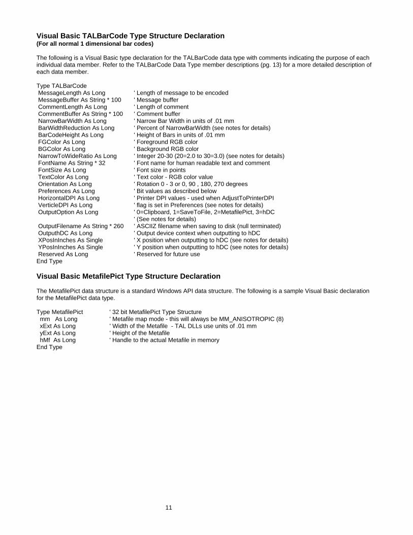
Visual Basic TALBarCode Type Structure Declaration (For all normal 1 dimensional bar codes) The following is a Visual Basic type declaration for the TALBarCode data type with comments indicating the purpose of each individual data member. Refer to the TALBarCode Data Type member descriptions (pg. 13) for a more detailed description of each data member. Type TALBarCode MessageLength As Long ' Length of message to be encoded MessageBuffer As String * 100 ' Message buffer CommentLength As Long ' Length of comment CommentBuffer As String * 100 ' Comment buffer NarrowBarWidth As Long ' Narrow Bar Width in units of .01 mm BarWidthReduction As Long ' Percent of NarrowBarWidth (see notes for details) BarCodeHeight As Long ' Height of Bars in units of .01 mm FGColor As Long ' Foreground RGB color BGColor As Long ' Background RGB color NarrowToWideRatio As Long ' Integer 20-30 (20=2.0 to 30=3.0) (see notes for details) FontName As String * 32 ' Font name for human readable text and comment FontSize As Long ' Font size in points TextColor As Long ' Text color - RGB color value Orientation As Long ' Rotation 0 - 3 or 0, 90 , 180, 270 degrees Preferences As Long ' Bit values as described below HorizontalDPI As Long ' Printer DPI values - used when AdjustToPrinterDPI VerticleDPI As Long ' flag is set in Preferences (see notes for details) OutputOption As Long ' 0=Clipboard, 1=SaveToFile, 2=MetafilePict, 3=hDC
' (See notes for details) OutputFilename As String * 260 ' ASCIIZ filename when saving to disk (null terminated) OutputhDC As Long ' Output device context when outputting to hDC XPosInInches As Single ' X position when outputting to hDC (see notes for details) YPosInInches As Single ' Y position when outputting to hDC (see notes for details) Reserved As Long ' Reserved for future use End Type Visual Basic MetafilePict Type Structure Declaration The MetafilePict data structure is a standard Windows API data structure. The following is a sample Visual Basic declaration for the MetafilePict data type. Type MetafilePict ' 32 bit MetafilePict Type Structure mm As Long ' Metafile map mode - this will always be MM_ANISOTROPIC (8) xExt As Long ' Width of the Metafile - TAL DLLs use units of .01 mm yExt As Long ' Height of the Metafile hMf As Long ' Handle to the actual Metafile in memory End Type

12
C/C++ TALBarCode Type Structure Declaration (For all normal 1 dimensional bar codes) The following is a C/C++ declaration for the TALBarCode data type with comments indicating the purpose of each individual data member. Refer to the TALBarCode Type Structure Elements (pg. 13) for a more detailed description of each data member. typedef struct tagTALBarCode { long messageLength; // Length of message to be encoded char messageBuffer[100]; // Message buffer long commentLength; // Length of comment char commentBuffer[100]; // Comment buffer long narrowBarWidth; // Narrow Bar Width in units of .01 mm long barWidthReduction; // Percent of NarrowBarWidth long barCodeHeight; // Height of Bars in units of .01 mm COLORREF fgColor; // Foreground Color COLORREF bgColor; // Background Color long narrowToWideRatio; // 20-30 (20=2.0 to 30=3.0) (see notes for details) char fontName[32]; // Font name for human readable text long fontSize; // Font size in points COLORREF textColor; // Text color - RGB color value long orientation; // Rotation 0 - 3 or 0, 90 , 180, 270 degrees long preferences; // Bit values as described below long horizontalDPI; // Printer DPI values - used when AdjustToPrinterDPI long verticleDPI; // flag is set in Preferences (see notes below) long outputOption; // 0=Clipboard, 1=File, 2=MetafilePict, 3=hDC char outputFilename[260]; // ASCIIZ filename when saving to disk HDC outputDC; // Output device context when outputting to hDC float XPosInInches; // X page position (when outputting to hDC) float YPosInInches; // Y page position (when outputting to hDC) long reserved; // Reserved for future use } TALBarCode; Note: The METAFILEPICT type structure is a standard Windows data structure therefore if you are writing your application in C/C++ then you do not have to declare this structure if you reference the INCLUDE file Windows.h in your project.

13
TALBarCode Type Structure Elements (For all normal 1 dimensional bar codes) Parameter Data Type Bytes Purpose Will Default? MessageLength Long 4 Specifies the length of the
message to be encoded No - Error is returned if length is zero or >100
MessageBuffer Character 100 Contains the message to be encoded
No
CommentLength Long 4 Specifies the length of the comment text
No - Error is returned if length is zero or >100
CommentBuffer Character 100 Contains the comment string No NarrowBarWidth Long 4 Width of the narrow bars in
units of .01 mm Yes, default is 33 (13 mils)
BarWidthReduction Long 4 Percentage of bar width reduction (or gain) Allowable range is 99% to -99% (gain)
Yes, default is 0 (i.e. no bar width reduction or gain)
BarCodeHeight Long 4 Height of the bars in units of .01 mm (not including message text or comment)
Yes, default is 2540 (1 inch)
FGColor Long 4 Specifies the foreground RGB color for all bars
Yes, default is Black (&H0F)
BGColor Long 4 Specifies the background RGB color. If set to &HFFFFFFFF then background is transparent
Yes, default is White (&HFFFFFF) if FGColor=0 and BGColor = 0
NarrowToWideRatio Long 4 Specifies the narrow to wide bar width ratio - can range from 20 to 30 representing 2.0 to 3.0
Yes, default is 25 representing a narrow to wide ratio of 2.5
FontName Character (ASCIIZ)
32 Name of the font for all human readable text
Yes, default is the System font
FontSize Long 4 Point size for text font Yes, default is 10 points TextColor Long 4 RGB color for human readable
text No
Orientation Long 4 Specifies rotation in 90 degree increments (0 - 3)
Yes, default is 0 or no rotation
Preferences Long 4 See description of preferences below
Yes, default is 0
HorizontalDPI Long 4 Horizontal dots per inch for output device. see notes below
No - used only if option AdjustToPrinterDPI is enabled
VerticalDPI Long 4 Vertical dots per inch for output device. see notes below
No - used only if option AdjustToPrinterDPI is enabled
OutputOption Long 4 Specifies how to output the bar code. see notes below
No
OutputFilename Character (ASCIIZ)
260 Output file name. required if outputting to a disk file
No - not required unless outputting to a disk file
OutputhDC Long 4 Device context handle for output device. required if outputting to a device context
No - not required unless outputting to a device context
XPosInInches Single 4 X coordinate for output position. used when outputting to a device context
Yes, default is 0
YPosInInches Single 4 Y coordinate for output position. used when outputting to a device context
Yes, default is 0
Reserved Long 4 Reserved for future use N/A

14
Visual Basic TALPDFBarCode Type Structure Declaration The following is a C/C++ declaration for the TALPDFBarCode data type with comments indicating the purpose of each individual data member. Refer to the TALBarCode Type Structure elements (pg. 13) and the TALPDFBarCode Type Structure Elements (pg.16) for a more detailed description of each data member. Type TALPDFBarCode MessageLength As Long ' Length of message to be encoded MessageBuffer As String * 2712 ' Message buffer CommentLength As Long ' Length of comment CommentBuffer As String * 100 ' Comment buffer PDFModuleWidth As Long ' PDF Module Width BarWidthReduction As Long ' Bar Width Reduction (0 to +-99%) PDFModuleHeight As Long ' PDF Module Height PDFAspect As Single ' PDF Symbol Aspect Ratio PDFSecurityLevel As Long ' PDF417 Security Level (0-8 or 9 for automatic) PDFCompactionMode As Long ' PDF Data Compaction Method PDFPctOverhead As Long ' Percent of Error Correction Overhead ' (used when automatic Security level option is selected) PDFMaxRows As Long ' Maximum number of rows in the PDF symbol PDFMaxCols As Long ' Maximum number of columns in the PDF symbol FGColor As Long ' Foreground RGB color BGColor As Long ' Background RGB color FontName As String * 32 ' Font name for comment text FontSize As Long ' Font size TextColor As Long ' Text color (RGB value) Orientation As Long ' Rotation 0 - 3 or 0, 90 , 180, 270 degrees Preferences As Long ' Bit values described below HorizontalDPI As Long ' Printer DPI values - used when AdjustToPrinterDPI VerticleDPI As Long ' flag is enabled in preferences OutputOption As Long ' 0=Clipboard, 1=SaveToFile, 2=MetafilePict, 3=hDC OutputFilename As String * 260 ' ASCIIZ filename (null terminated) OutputhDC As Long ' Output device context (when outputting to hDC) XPosInInches As Single ' X page position (when outputting to hDC) YPosInInches As Single ' Y page position (when outputting to hDC) Reserved As Long ' Reserved for future use End Type

15
C/C++ TALPDFBarCode Type Structure Declaration (For 2 dimensional PDF417 bar codes) The following is a C/C++ declaration for the TALPDFBarCode data type with comments indicating the purpose of each individual data member. Refer to the TALBarCode Type Structure elements (pg. 13) and the TALPDFBarCode Type Structure Elements (pg.16) for a more detailed description of each data member. typedef struct tagTALPDFBarCode { long messageLength; // Length of message to be encoded char messageBuffer[2712]; // Message buffer long commentLength; // Length of comment char commentBuffer[100]; // Comment buffer long PDFModuleWidth ; // PDF Module Width long BarWidthReduction; // Bar Width Reduction (0 to +-99%) long PDFMod uleHeight; // PDF Module Height float PDFAspect; // PDF Symbol Aspect Ratio long PDFSecurityLevel; // PDF417 Security Level (0-8 or 9 for automatic) long PDFCompactionMode; // PDF Data Compaction Method long PDFPctOverhead; // Percent of Error Correction Overhead // (when "auto" Security level option is selected) long PDFMaxRows; // maximum number of rows in the PDF symbol long PDFMaxCols; // Maximum number of columns in PDF symbol COLORREF fgColor; // Foreground Color COLORREF bgColor; // Background Color char fontName[32]; // Font name for human readable text long fontSize; // Font size in points COLORREF textColor; // Text color - RGB color value long orientation; // Rotation 0 - 3 or 0, 90 , 180, 270 degrees long preferences; // Bit values as described below long horizontalDPI; // Printer DPI values - used when AdjustToPrinterDPI long verticleDPI; // flag is set in Preferences long outputOption; // 0=Clipboard, 1=File, 2=MetafilePict, 3=hDC char outputFilename[260]; // ASCIIZ filename when saving to disk HDC outputDC; // Output device context when outputting to hDC float XPosInInches; // X page position (when outputting to hDC) float YPosInInches; // Y page position (when outputting to hDC) long reserved; // reserved for future use } TALBarCode;

16
TALPDFBarCode Type Structure Elements (For 2 dimensional PDF417 bar codes) Parameter Data Type Bytes Purpose Will Default?
MessageLength Long 4 Specifies the length of the message to be encoded
No - Error is returned if length is negative, zero or >2712
MessageBuffer Character 2712 Contains the message to be encoded No CommentLength Long 4 Specifies the length of the comment
text No - Error is returned if length is negative, zero or >100
CommentBuffer Character 100 Contains the comment string No PDFModuleWidth Long 4 Width of the smallest PDF417 module
in units of .01 mm Yes, default is 25 (10 mils)
BarWidthReduction Long 4 Percentage of bar width reduction (or gain) Range is 99% to -99% (gain)
Yes, default is 0 (i.e. no bar width reduction or gain)
PDFModuleHeight Long 4 Height of smallest PDF417 codeword module in units of .01 mm
Yes, default is 76 (30 mils)
PDFAspect Single 4 Symbol aspect ratio (desired overall height to width ratio)
Yes, .5 - overall symbol width will be twice the height
PDFSecurityLevel Long 4 PDF417 security level (0-9) 9=automatic based on % of symbol area to use for error correction
No
PDFCompactionMode Long 4 PDF417 data compaction mode (0-3) Yes- automatic (9) PCTOverhead Long 4 Percentage of symbol area to use for
error correction when PDFSecurityLevel option is set to 9 (automatic)
Yes, 11% Only used if PDFSecurityLevel is set to 9 (automatic)
PDFMaxRows Long 4 Maximum number of codeword rows to allow
Yes, default is 90
PDFMaxCols Long 4 Maximum number of codeword columns to allow
Yes, default is 30
FGColor Long 4 Specifies the foreground RGB color for all bars
Yes, default is Black (&H0)
BGColor Long 4 Specifies the background RGB color. If set to &HFFFFFFFF then background is transparent
Yes, default is White (&HFFFFFF) if FGColor=0 and BGColor=0
FontName Character (ASCIIZ)
32 Name of the font for all human readable text
Yes, default is the System font
FontSize Long 4 Point size for text font Yes, default is 10 points TextColor Long 4 RGB color for human readable text No Orientation Long 4 Specifies rotation in 90 degree
increments (0 - 3) Yes, default is 0 or no rotation
Preferences Long 4 See description of preferences below Yes, default is 0 HorizontalDPI Long 4 Horizontal dots per inch of output
device. see notes below No - used only if option AdjustToPrinterDPI is enabled
VerticalDPI Long 4 Vertical dots per inch of output device. See notes below
No - used only if option AdjustToPrinterDPI is enabled
OutputOption Long 4 Specifies how to output the bar code. See notes below
No
OutputFilename Character (ASCIIZ)
260 Output file name. required if outputting to a disk file
No - not required unless outputting to a disk file
OutputhDC Long 4 Device context handle for output device. required if outputting to a device context
No - not required unless outputting to a device context
XPosInInches Single 4 X coordinate for output position. used when outputting to a device context
Yes, default is 0
YPosInInches Single 4 Y coordinate for output position. used when outputting to a device context
Yes, default is 0
Reserved Long 4 Reserved for future use N/A

17
TALBarCode Data Type Member Descriptions and Notes MessageLength The MessageLength parameter specifies the length of message to be encoded. The allowable range for this parameter is 1 to 100 for all 1 dimensional bar codes and 1 to 2712 for PDF417. The actual message will be passed in the MessageBuffer parameter. Normally strings are passed to DLLs as ASCIIZ or "Null Terminated" strings where an ASCII zero is used to indicate the end of the string. The problem with using this technique is that some bar code symbologies like Code 39 (Full ASCII version), Code 128 and PDF417 allow you to encode ASCII zeros in a bar code. If we were to use ASCIIZ strings and a particular bar code message were to contain an ASCII zero character, Windows would truncate the message at the ASCII zero. MessageBuffer Contains the message that you want encoded. Note: Different symbologies allow different sets of characters to be encoded. For example UPC, EAN, PostNET and Interleaved 2 of 5 can only encode numeric digits (0-9) and CodaBar can only encode numeric digits and the alpha characters A,B,C and D. If you pass a message that contains illegal characters for a particular symbology, the DLL call will fail and an "Invalid Message" error code will be returned. Note: When specifying UPC A, UPC E, EAN 8, EAN 13 and BookLand bar code messages, to include a 2 or 5 digit supplemental message, append the 2 or 5 digit supplemental message to the main message with a comma between them. For additional information on how to specify messages refer to the Symbology Descriptions and Rules (starting on pg. 37) for the particular bar code symbology that you are using. CommentLength Specifies the length of an optional comment that you want to appear either above or below the bar code. The allowable range is 0 to 100. Zero means that you do not want a comment in the bar code. The position of the comment is specified using a flag in the "Preferences" variable. (See the notes for the Preferences variable on pg. 24 for additional information.) CommentBuffer Contains the comment message. Comments can contain any ASCII character. NarrowBarWidth The NarrowBarWidth (expressed in integer units of .01 mm) specifies the width of the narrowest bar in the bar code. All other bar and space width dimensions are based on this width (referred to as the nominal X dimension). This parameter as well as the number of characters to encode, effectively determines the total width of a bar code symbol. The best choice for this dimension depends partly on the resolution of your bar code reading equipment and also on the resolution of the printer being used to produce the bar code. As a general rule the Narrow Bar Width should fall in a range between 10 to 30 mils (25 to 76 in units of .01 mm) and should never be less than 7.5 mils. 13 mils (or .33 mm) is the most commonly recommended value for most bar code readers). For UPC and EAN bar codes, the smallest allowable Narrow bar width is 10.4 mils (.26 mm). The allowable range of values for NarrowBarWidth in the TAL Bar Code DLLs is 0 to 500. If you pass the value zero, the default value of 33 (13 mils) will be used.

18
BarWidthReduction The BarWidthReduction parameter allows you to set a Reduction or Gain factor ranging from 99 (% reduction) to -99 (% gain). Specifying a non-zero value for the BarWidthReduction parameter causes the DLL to reduce or enlarge the width of all solid bars in a bar code. Bar Width Reduction is often necessary to compensate for ink spread when generating bar codes that will be used in wet ink printing processes. The percentage that you specify is based on the narrow bar width that you choose for your bar codes. For example if you specify a BarWidthReduction value of 25 and your narrow bar width is set at 10 mils, the width of all bars in your bar codes will be reduced by 2.5 mils (25% of 10 mils = 2.5 mils). Bar width gain is typically used when printing on glass or other surfaces that cause ink to bead up or shrink as it dries. To specify bar width gain instead of reduction, use a negative percentage value. An error is returned if you specify a BarWidthReduction value greater than 99 or less than -99. BarCodeHeight Specifies the height of the bars in units of .01 mm. The allowable range for this parameter is 100 to 20000 or zero. If you specify zero as the BarCodeHeight, the default value of 2540 (1 inch) will be used. FGColor & BGColor Specifies the Foreground and Background RGB colors for your bar codes. If both the FGColor and the BGColor parameters are set to zero then the default values of black bars on a white background will be used. The allowable range of color values is 0 representing black to 16777215 (hex &HFFFFFF) representing white. If you specify &HFFFFFFFF as the background color, then the background will be transparent. Note: It is entirely possible to choose color combinations that render a bar code symbol unreadable. Although two colors may appear to the human eye to have a high of contrast between them, a bar code reader may not be able to determine any difference at all between the two colors. Solid black bars on a solid white background always produces the best results. If you must use colors other than black on white, a good rule of thumb is to select solid foreground colors with a luminescence value no greater than 60 and select solid background colors with a luminescence value no less than 180. See Also: How To Produce Readable Bar Codes (pg. 31) NarrowToWideRatio The symbologies Code 39, Interleaved 2 of 5 and CodaBar consist of bars and spaces with only two element widths, Narrow and Wide Elements where the width of the wide elements is a fixed multiple of the width of the narrow elements. The specifications for these symbologies allow you to choose a Narrow to Wide Element Ratio ranging from 2.0 to 3.0. The TAL bar code DLLs require that you pass the NarrowToWideRatio parameter as an integer ten times the actual desired value. (i.e. ranging from 20 to 30 representing 2.0 to 3.0). If you specify zero as the NarrowToWideRatio, the default of 25 (representing 2.5) will be used. This parameter is valid only for Code 39, Interleaved 2 of 5 and CodaBar. All other symbologies will ignore this parameter. The rules for these symbologies specify that when the Narrow Bar Width is less than 20 mils, the Narrow To Wide element ratio must be 2.2 or greater. The default NarrowToWideRatio of 2.5 should be acceptable for most applications.

19
Note: Higher quality readers may be able to read bar codes with a narrow to wide ratio less than 2.2 no matter what the narrow element width is. Lower quality readers often need a ratio of at least 2.5. Because of the variability between readers, you should always test different ratio values and select the value that produces bar codes with the best "first pass" read rate. FontName The FontName parameter allows you to choose the font for the human readable text in your bar codes. If you do not specify a font name, the DLL will use the default "System" font. Different fonts behave differently thus some fonts may appear different on screen than when printed. True Type fonts are the most WYSIWYG and they also align better when rotated. Note: Most bar code symbology specifications recommend the font OCR-B (Optical Character Recognition revision B). The choice of font is not critical however it is a good idea to choose fonts that are close to the recommended specification. The System font and the font MS Sans Serif are both very close to OCR-B as is the True Type Font Arial. FontSize Specifies the font size in points for all human readable text. The allowable range is zero to 1000 points. If you specify zero then the default font size of 10 points will be used. Note: When the Automatic Font Scaling option is used in the Preferences variable, it will override any font size entered for the FontSize parameter. See the Preferences parameter for details. TextColor Specifies the foreground RGB color for all human readable text. The allowable range of color values is 0 representing black to 16777215 (hex &HFFFFFF) representing white. Orientation The Orientation parameter allows you to rotate a bar code symbol in increments of 90 degrees from horizontal. Four choices of orientation are available, 0, 1, 2 and 3. Specifying 0 tells the DLL to produce normal Horizontal bar codes. Specifying 1 causes the bar code to be rotated 90 degrees clockwise (Vertical), specifying 2 rotates the bar code 180 degrees (upside down) and specifying 3 rotates the bar code 270 degrees clockwise (vertical). If you specify a value that is outside the allowable range of 0 to 3, the DLL will perform a logical AND on the number that you supply with the value 3 and then use the resulting value. Preferences The Preferences option allows you to choose specific options available in each bar code symbology by setting bit values in the Preferences variable. You enable a particular preference option by ORing the Preferences variable with a particular constant value. See the Preferences section of this manual (pg. 24) for a complete description of all available Preferences options and their respective constant values. HorizontalDPI and VerticleDPI The HorizontalDPI and VerticleDPI parameters only have meaning when the Pref_AdjustToPrinterDPI option is set in the Preferences variable. See the notes for the preferences variable for details (pg. 24).

20
OutputOption The OutputOption variable allows you to select the method that the DLL will use to output your bar codes. The TAL Bar Code DLLs support four possible output options that are selected by using the following values:
Option Value Output Action OutputToClipboard 0 Places the bar code in the Windows clipboard. OutputToDiskFile 1 Stores the bar code in a disk file as a WMF file. OutputToMemoryMetafile 2 Stores the bar code in a memory Metafile. OutputTohDC 3 Paints the bar code to a device context.
The OutputToClipboard and OutputToDiskFile options are typically used when the programming language that you are using does not provide access to device context handles for screen windows. Visual Basic for Applications (as in MS Word and Access) is one such language (not to be confused with Microsoft Visual Basic). Because you do not have access to device context handles, you cannot use the PlayMetafile Windows API function to render your bar codes on screen. You can however retrieve graphics from the clipboard or from a disk file in VBA and most other similar languages. Note: When outputting to a disk file, you have the option of storing the Metafile as a standard Windows Metafile or as an Aldus Placeable Metafile. The default is to store a standard Windows Metafile. To create an Aldus Placeable Metafile, you use the Pref_MakeAldusMetafile constant with the Preferences parameter. Note: All newer versions of Word, Access and most other Microsoft applications require Aldus Placeable Metafiles and will not recognize standard Metafiles. The OutputTohDC option can be used to have the DLL perform almost all of the work of creating and also rendering the bar code directly on a device context (hDC). This option is the most powerful because the DLL does everything for you including create the bar code, render it on a device and also delete the Metafile from memory. For simpler applications that require small numbers of bar codes, this option is probably the best because it requires the least additional code and it cleans up after itself leaving you little to worry about. The OutputToMemoryMetafile option is the most flexible of the four options because it creates the bar code to a memory based Metafile and then leaves it in memory so that you can access it as needed. C/C++ programmers will probably find this method to be the best one to use. The Metafile is accessed using a Metafile handle (hMF) that is passed back to your application in a MetafilePict type structure. The MetafilePict structure contains several parameters including size information and the handle to the Metafile (hMF) containing your bar code. The hMF parameter in the MetafilePict structure (returned by the DLL call) will be zero for all output options except when outputting to a memory Metafile.

21
Important: When you output to a memory Metafile, your application is responsible for deleting the Metafile when it is no longer needed by calling the Windows API function DeleteMetafile. If you do not delete the Metafile, it will stay in memory after your application exits resulting in a "memory leak". The OutputToMemoryMetafile option is the most flexible way to use the bar code DLLs because you only need to create each bar code once. After a bar code has been created, you can output it to the screen, the printer or both as necessary without having to create it again. When the DLL is called to output to either the clipboard, a disk file or directly to a hDC, the DLL will delete the Metafile from memory thus saving you the trouble. In these cases the DLL will set the hMF member of the MetafilePict returned by the DLL to zero. OutputFileName The OutputFileName parameter is the name and path for a disk file where you would like your bar code saved. This parameter is required when you use the "OutputToDiskFile" Output Option. For all other output options this parameter is ignored. The file name must be passed as a null terminated string (ASCIIZ). If you pass an illegal file name, the DLL function call will fail and return an "Invalid Filename" error. Note: For the 32 bit DLLs you must define the OutputhFileName as a string * 260 (this is the longest allowable path name in 32 bit versions of Windows, i.e. for "Long File Names"). OutputhDC The OutputhDC parameter is the device context handle (hDC) for the output device where you would like your bar code displayed or printed. This parameter is required when you use the "OutputTohDC" Output Option. For all other output options this parameter is ignored. XPosInInches and YPosInInches The XPosInInches and YPosInInches variables are used to specify the position on a device context (printer page or screen window) where you would like your bar code drawn when you use the output option "OutputTohDC". Since the DLL will be drawing the bar code directly to the device, these parameters let you specify the coordinates on the page or window (in inches) for the upper left corner of your bar code. These parameters are only valid when the output option is set to "OutputTohDC" and are ignored for all other output options. These parameters are expected as positive values with the upper left corner of the page being position 0,0. The values passed to the DLL must fall within the height and width of the screen window or the printer page sizes for the output device. Since these values are passed as single precision variables and not integers, you can specify fractional coordinate values.

22
Parameters Specific to the TALPDFBarCode Type Structure PDFModuleWidth Specifies the width of the smallest PDF417 code word module in units of .01mm. This parameter is similar to the NarrowBarWidth parameter for standard 1 dimensional bar code symbologies. The specification for PDF417 recommends that the Module Width should fall in a range between 10 and 30 mils (.25mm to .76mm). The smallest allowable module width defined in the symbology specification is 6.56 mils (.17mm). This translates to 2 printer dots when printing to a 300 DPI laser printer. The best way to determine the ideal Module Width for your application is to actually print out a sample bar code using several different values and try reading each one with your scanning equipment. You should choose the value that produces bar codes with the best read-rate. PDFModuleHeight Specifies the height of the smallest PDF417 code word module in units of .01mm. The recommended value for the Module Height is approximately three times the value for the PDFModuleWidth however the symbol specifications allow for module heights as small as 10 mils (.25mm). This translates to 3 printer dots on a 300 DPI laser printer. PDFAspect The PDFAspect determines the overall shape of the PDF417 symbol and is defined as the overall height to width ratio. Higher values for the Aspect Ratio (greater than 1) produce tall, thin PDF417 bar codes and small values (greater than zero and less than 1) produce short, wide bar codes. A value of 1 should produce approximately square bar codes. Refer to the Symbology Descriptions and Rules for PDF417 (pg. 46) for a further explanation of PDF aspect ratios. PDFSecurityLevel The PDFSecurityLevel parameter allows you to select a PDF417 error correction level from 0 to 8 (or 9 for automatic). Each higher security level up to 8 adds additional overhead to a PDF417 symbol thereby consuming more symbol real estate. You can have the TALPDF DLL automatically select an error correction level based on a percentage of total symbol area that you want to devote to error correction. If you pass the value 9 for the PDFSecurityLevel and also pass a percentage value (from 0 to 99%) in the PDFPctOverhead parameter, the DLL will automatically choose a value that will limit the amount of error correction overhead to the given percentage of symbol area. This option is designed so that you do not waste space on redundant error correction. Refer to the Symbology Descriptions and Rules for PDF417 (pg. 46) for a further explanation of PDF error correction capabilities.
23
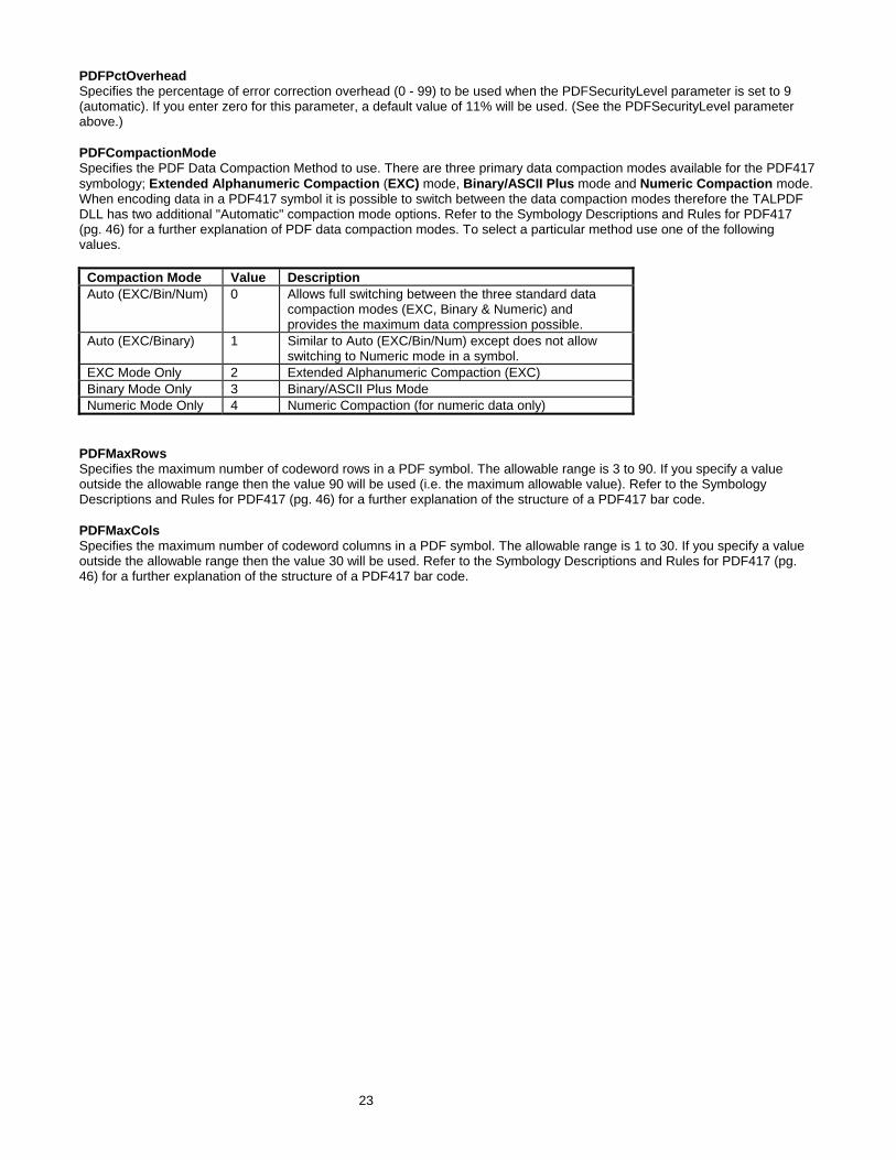
PDFPctOverhead Specifies the percentage of error correction overhead (0 - 99) to be used when the PDFSecurityLevel parameter is set to 9 (automatic). If you enter zero for this parameter, a default value of 11% will be used. (See the PDFSecurityLevel parameter above.) PDFCompactionMode Specifies the PDF Data Compaction Method to use. There are three primary data compaction modes available for the PDF417 symbology; Extended Alphanumeric Compaction (EXC) mode, Binary/ASCII Plus mode and Numeric Compaction mode. When encoding data in a PDF417 symbol it is possible to switch between the data compaction modes therefore the TALPDF DLL has two additional "Automatic" compaction mode options. Refer to the Symbology Descriptions and Rules for PDF417 (pg. 46) for a further explanation of PDF data compaction modes. To select a particular method use one of the following values.
Compaction Mode Value Description Auto (EXC/Bin/Num) 0 Allows full switching between the three standard data
compaction modes (EXC, Binary & Numeric) and provides the maximum data compression possible.
Auto (EXC/Binary) 1 Similar to Auto (EXC/Bin/Num) except does not allow switching to Numeric mode in a symbol.
EXC Mode Only 2 Extended Alphanumeric Compaction (EXC) Binary Mode Only 3 Binary/ASCII Plus Mode Numeric Mode Only 4 Numeric Compaction (for numeric data only)
PDFMaxRows Specifies the maximum number of codeword rows in a PDF symbol. The allowable range is 3 to 90. If you specify a value outside the allowable range then the value 90 will be used (i.e. the maximum allowable value). Refer to the Symbology Descriptions and Rules for PDF417 (pg. 46) for a further explanation of the structure of a PDF417 bar code. PDFMaxCols Specifies the maximum number of codeword columns in a PDF symbol. The allowable range is 1 to 30. If you specify a value outside the allowable range then the value 30 will be used. Refer to the Symbology Descriptions and Rules for PDF417 (pg. 46) for a further explanation of the structure of a PDF417 bar code.

24
Preferences Options and Constants: Note: To use one or more preferences options, perform a logical OR using the desired preferences constants and pass the result to the DLL in the Preferences variable in the TALBarCode structure. For example to turn off the human readable text and include quiet zones in a bar code you could use the following code in Visual Basic: Const Pref_DoNotDisplayText = 1 Const Pref_QuietZones = 8 Dim MyBarCode as TALBarCode MyBarCode.Preferences = Pref_DoNotDisplayText OR Pref_QuiteZones Pref_DoNotDisplayText = 1 Disables the display of the human readable message text. Pref_TextOnTop = 2 Instructs the DLL to place the human readable message text above the bar code. Normally the human readable message text is placed below the bar code symbol. Pref_CommentOnBottom = 4 Instructs the DLL to place the comment text below the bar code. Normally the comment text is placed above the bar code symbol. Pref_QuietZones = 8 Causes the DLL to add blank space at either end of a bar code image. This space, called Quiet Zones, helps to insure that a bar code reader will be able to correctly determine the true beginning and end of a bar code symbol. The width of the quiet zones will be 10 times the NarrowBarWidth parameter for all 1 dimensional symbols and 2 times the PDFModuleWidth value for PDF417 bar codes. For Maxicode bar codes the quite zone will be .88mm on the left and right sides of each symbol and .76mm on the top and bottom of each symbol. Most bar code symbology specifications require quiet zones therefore it is recommended that you enable this option. Note: UPC, EAN and Bookland bar codes automatically include quiet zones in the symbol. Selecting this option causes the width of the quiet zones in these symbols to be twice the normal width. Pref_BearerBars = 16 Causes the DLL to draw lines surrounding a bar code symbol. The purpose of bearer bars is to equalize the pressure exerted by a printing plate over the entire surface of the symbol. Bearer bars also enhance the reading reliability of a bar code by reduction of the probability of misreads or short scans which may occur when a skewed scanning beam enters or exits the symbol through the top or bottom edge of the bar code. When the scanner path leaves the symbol either through the top or bottom, it crosses the bearer bar, thereby resulting in an invalid start/stop code. Only the symbologies: Code 39, Code 93, Interleaved 2 of 5, CodaBar and Code 128 support bearer bars. This option is ignored by all other symbologies. Pref_Code39FullASCII = 32 Causes the TALC39 DLL to use the Full ASCII version of Code 39 instead of the normal Code 39. See the Symbology Descriptions and Rules for Code 39 (pg. 37) for details.

25
Pref_DisplayStartStopChars = 64 Causes the TALC39 DLL to display the Code 39 start and stop characters as asterisks (*) in the human readable text portion of a Code 39 bar code. This value is not valid for any other symbology. See the Symbology Descriptions and Rules for Code 39 (pg. 37) for details. Pref_BookLand = 64 Causes the TALEAN32.DLL to use the BookLan symbology instead of a normal EAN bar code. This constant is not valid for any other symbology. See the Symbology Descriptions and Rules for the EAN 8, EAN 13 and BookLand symbologies (pg. 40) for details. Pref_EANUCC128 = 64 Causes the TAL12832.DLL to use the EAN/UCC 128 symbology instead of a normal Code 128 bar code. This constant is not valid for any other symbology. See the Symbology Descriptions and Rules for Code 128 and EAN/UCC 128 (pg. 44) for details. Pref_Code39HIBC = 384 Causes the TALC3932.DLL to use the HIBC version of Code 39 instead of the normal version of Code 39. See the Symbology Descriptions and Rules for Code 39 (pg. 37) for details. Pref_OptionalCheckDigit1 = 128 Pref_OptionalCheckDigit2 = 256 Causes the DLL to calculate and append a check digit to a bar code message. Different symbologies allow different types of check digit calculations as listed in the following table. Note: Some bar code symbologies incorporate a check digit as a standard feature of the symbology. For example UPC, EAN, Code 93 and Code 128 all require a check digit and therefore it is not an option. The TAL Bar Code DLLs will always calculate and append all required check digits according to the specifications of the chosen symbology. The Optional Check digit options allow you to instruct the DLL to add check digits in addition to any standard check digits.
Symbology Pref_OptionalCheckDigit1 Pref_OptionalCheckDigit2 Code 39 Modulo 43 Add HIBC Start Character Extended Code 39 Modulo 43 Add HIBC Start Character Interleaved 2 of 5 Modulo 10 CodaBar Modulo 16 EAN/UCC 128 Modulo 10
Note: If the optional check digit for EAN/UCC 128 is enabled, the message must consist of numeric digits only otherwise the DLL function will fail and return an "Invalid Message" error. Pref_DisplayCheckDigit = 512 Causes optional check digits to be appended to the human readable text in a bar code. Typically any optional check digits are not included in the human readable portion of a bar code symbol however there are some applications where you may want to display the check digit. This option is only valid for symbologies that support an optional check digit. Note: The optional check digit for EAN/UCC 128 will be displayed with the human readable text regardless of whether this option is selected or not.

26
Pref_FontBold = 1024 Causes the font for all human readable text to be displayed in bold. Pref_FontItalic = 2048 Causes the font for all human readable text to be displayed in italics. Pref_FontUnderLine = 4096 Causes the font for all human readable text to be displayed underlined. Pref_FontStrikeOut = 8192 Causes the font for all human readable text to be displayed with a line through the center of each character. Pref_AutoFontScaling = 16384 Causes the DLL to automatically scale all text to a font size that is approximately one fifth the height of the generated bar code symbol. This option overrides any value that you specify for the FontSize parameter. Pref_AdjustToPrinterDPI = 32768 Causes the DLL to adjust the narrow bar width to be as close as possible to an integer multiple of the size of a single printer dot. Since a printer cannot print a partial dot, if the width of the bars in a bar code are not an exact multiple of the size of a printer dot, the printer driver will round the bar widths to get as close to a desired line width as it can. This rounding can distort a bar code slightly because some bars might be rounded up and some might be rounded down. Selecting this option causes the DLL to adjust the narrow bar width so that any rounding will be minimized. If you enable this option then you will also be required to supply values for the HorizontalDPI and VerticleDPI parameters to indicate the resolution (in dots per inch) for your printer. Pref_TruncatedPDF = 16 Causes the TALPDF32.DLL to create truncated PDF417 symbols. For a complete discussion of the truncated version PDF417 symbols, see page. 50). Pref_MakeAldusMetafile = 65536 Causes the DLL to save Metafiles to disk using the "Aldus Placeable Metafile" format. This format is a variation of the standard Windows Metafile that is required by many popular applications including all Microsoft Office applications (Word, Access and Excel, etc.) Aldus Placeable Metafiles are identical to standard Windows Metafiles except that they have a special 22-byte header that contains the overall dimensions of the graphic as well as a special code that identifies the file as an Aldus Placeable Metafile. This option is ignored except when outputting bar codes to a disk based Metafile (i.e. when the OutputOption variable is set to "OutputToDiskFile"). Pref_CommentAlignCenter = 131072 Pref_CommentAlignRight = 262144 These options set the alignment of any optional comment text. The Pref_CommentAlignCenter option causes the comment to be center aligned and the PrefCommentAlignRight option causes it to be right aligned. If you do not supply an optional comment, these parameters are ignored. The comment text will appear above the bar code unless you also OR the Preferences variable with the Pref_CommentBelow constant.

27
Pref_AztecMenuCode = 16 Instructs the Aztec Code DLL (TALAzt32.DLL) to generate an Aztec Menu Symbol instead of a normal Aztec code symbol. Pref_Standard_ASCII = 16 Instructs the Data Matrix DLL (TALDM32.DLL) to interpret all input data as standard ASCII data. When this option is in effect, the Data Matrix DLL will not scan through the input data looking for any special "Tilde Codes" and will encode all data in the input message as is - including tilde characters. Tilde Control Codes are special codes that can be used to take advantage of special features of Data Matrix including Function Codes (FNC1), Structured Append, and Extended Channel Interpretation. They are called Tilde Control Codes because the tilde character (~) is used to signal that the character(s) immediately following the tilde are to have special meanings to the encoder. Please refer to the description of the Data Matrix symbology in this document for a complete list of the available Tilde Codes.

Bar Code Dimensions Because of differences in the design of each bar code symbology, there are differences in the way that the dimensions for each symbology are expressed. The two main dimensions used to define the size of most common bar codes are the Narrow Bar Width and the overall Bar Height. The Height is generally less important than the Narrow Bar Width and you can scale the height to any size that you like. For the sake of readability the height should not be less than a quarter of an inch or 15% of the total width of the symbol, whichever is greater. UPC and EAN bar codes have more specific size requirements if they are to be used for product identification. For details refer to the Symbology Descriptions and Rules for UPC and EAN (pg. 39-40) and UPC and EAN Magnification Factors (pg. 41). The Narrow Bar Width effectively determines the total width of a bar code symbol. All other bar and space width dimensions are based on this width (referred to as the nominal X dimension). The best choice for this dimension depends partly on the resolution of your bar code reading equipment and also on the resolution of the printer being used to produce the bar code. As a general rule the Narrow Bar Width should fall in a range between 10 to 30 mils (.25 to .76mm) and should never be less than 7.5 mils (13 mils (.33mm) is the most commonly recommended value for most bar code readers). For UPC and EAN bar codes, the smallest allowable Narrow bar width is 10.4 mils (.26mm). One way to determine a good Narrow Bar Width is to actually print out a typical bar code using several different values and then try reading each one with your scanning equipment. You should choose the value that produces bar codes with the highest "first pass" read rate.
X = 1 3 S a m p l e
X = 2 0 S a m p l e
28

Bar Code Basics Bar code is an automatic identification technology that allows data to be collected rapidly and with extreme accuracy. Because of this, bar code technology is finding its way into a broad range of applications in almost every sector of business. Bar codes provide a simple and easy method of encoding text information that is easily read by inexpensive electronic readers. A bar code consists of a series of parallel, adjacent bars and spaces. Pre-defined bar and space patterns or symbologies are used to code character data into a printed symbol. Bar codes can be thought of as a printed version of the Morse code with narrow bars representing dots, and wide bars representing dashes. A bar code reading device decodes a bar code by scanning a light source across the bar code and measuring the intensity of light reflected back to the device. The pattern of reflected light produces an electronic signal that exactly matches the printed bar code pattern and is easily decoded into the original data by inexpensive electronic circuits. Due to the design of most bar code symbologies it does not make any difference if you scan a bar code from right to left or from left to right. Shown Below is the structure of a typical bar code symbol.
QU
IET
ZON
E
QU
IET
ZON
E
Start StopCheck1 3
The basic structure of a bar code consists of a leading and trailing quiet zone, a start pattern, one or more data characters, optionally one or two check characters and a stop pattern. There are a variety of different types of bar code encoding schemes or "symbologies", each of which were originally developed to fulfill a specific need in a specific industry. Several of these symbologies have matured into de-facto standards that are used universally today throughout most industries. The symbologies supported by the TAL Bar Code DLLs are those most commonly used across all industries. For more information about specific bar code symbologies see: Symbology Descriptions And Rules (pg. 37).
29

How A Bar Code Reader Works A bar code reader works by scanning a dot of light across a bar code symbol. As the dot scans across the bar code, light is reflected back to the bar code reader by the light areas and is absorbed by the dark areas. The scanner electronically measures the intensity of the light reflected back to produce a digitized waveform that can be decoded back to the original message similar to the way morse code dots and dashes are decoded.
Dot Of Light
Digitized Signal
Bar code scanners can be purchased with different resolutions to enable them to read bar codes of different sizes. The scanner resolution is measured by the size of the dot of light. The dot of light should be equal to or slightly smaller than the narrowest element width ("X" dimension). If the dot is wider than the width of the narrowest bar or space, then the dot of light will overlap two or more bars at a time and there will not be sharp transitions in the digitized waveform produced by circuit that measures the intensity of the light reflected back to the reader. If the dot is too small, then any spots or voids in the bars can be misinterpreted as light areas thus making a bar code unreadable. The factors that make a bar code readable are: an adequate print contrast between the light and dark bars and having all bar and space dimensions within the tolerances for the symbology. It is also helpful to have sharp bar edges, few or no spots or voids, a smooth surface and clear margins or quiet zones at either end of the printed symbol.
30

31
How To Produce Readable Bar Codes Although there are many different types of bar codes, they all share the same requirements in order to be readable by most commercially available scanning devices. Because a beam of light is used to read a bar code, it should be clean and free of defects or smudges and there should be a high contrast between the color of the bars and the color of the spaces. Black bars on a white background yield the best results. If you intend to use colored bar codes or colored paper, you should always test the readability of your bar codes before committing to a color scheme. Another important consideration is that there should always be a small amount of space or Quiet Zones preceding and following the bar code so that the reading device is able to properly determine the true start and end of the bar code symbol. A good rule of thumb is to reserve at least a quarter of an inch or 10 times the width of a single narrow bar (whichever is greater) for blank space at either end of a bar code. The TAL Bar Code DLLs will automatically include Quiet Zones of ten times the narrow bar width if the "Pref_QuietZones" option is enabled in the Preferences variable. When printing bar codes, laser, ink jet and thermal transfer printers produce the best results. Dot matrix printers produce the poorest quality (but not necessarily unacceptable) bar codes. Dot matrix printers are especially poor when the bar code dimensions are set to a small size. You should try to avoid very small or very large bar codes, both narrow bar widths and overall bar code dimensions. As a precaution you should always test your printed output with whatever bar code reading equipment you eventually intend to use. See Also: Symbology Descriptions and Rules (pg. 37) Special Considerations And Incompatibilities (pg. 35)

32
A Word About Graphic File Formats A bar code is comparable to a printed version of the Morse code. Instead of dots and dashes to represent characters, bar codes use the widths of bars and spaces. It is extremely important that the widths of the bars and spaces are printed within tight tolerances if you want your bar codes to be readable. How the bar code is produced including the type of graphic that is originally used is therefore extremely important. Microsoft Windows supports two native graphic formats that are commonly used to create bar codes; bitmaps and Metafiles. Fonts can also be used to create bar codes however fonts generally produce poor to unacceptable results. For any serious commercial application, fonts should be avoided at all costs. Bitmaps (Raster Graphics) A bitmap is an array of dots or “pixels” where each pixel (picture element) has a value that represents the color of the pixel. Any graphic made up of rows of dots is called a “Raster” graphic. Most graphic formats including TIF, GIF, DIB, etc. are also raster graphics. When you create a bitmap, the width of the bitmap is determined by the number of pixels across a row. The height of the bitmap is determined by the number of rows. The overall printed dimensions of the bitmap is dependent on the dot resolution of the device used to print the bitmap. For example if you create a bitmap graphic that is 300 pixels wide and has 300 rows of pixels and then you print this bitmap on a printer that has a dot resolution of 300 dots per inch, you will end up with a printed image one inch square. If you display the same bitmap on a computer screen that has a dot resolution of 100 dots per inch, you end up with an image that is three inches square. This means that bitmaps are “device dependent” where the resolution of the rendering device (i.e. printer or screen) must be taken into consideration when you create the bitmap. If you need to preserve the size of an image from one device to another, (i.e. screen to printer) you must “stretch” or “shrink” a bitmap to fit the desired size. The process of stretching and shrinking involves either adding or removing pixels to or from the original image. As you can imagine resizing a bitmap to fit a desired size when moving from one output device to another generally causes a severe distortion of the original image. When creating precise raster graphics (like bar codes) it is extremely important that the image is created with the same dot resolution of the printer. If you do not know the dot resolution of the printer that will be used to print the bar code then you cannot fully guarantee that it will be readable by all bar code readers. Bitmaps also require large amounts of memory and storage space. For example a bitmap that is 300 pixels wide and 300 lines down (only 1 square inch on a 300 DPI laser printer) and has three bytes per pixel of color information (standard RGB colors) will require 270,000 bytes of memory or disk space. For bar codes, this is a huge amount of space for a very simple graphic made up of only a small number of rectangles and a few text characters.

33
Vector Graphics and Metafiles The absolute best way to create bar codes is to use a vector style graphic. Instead of containing an actual raster style image (like a bitmap), a vector graphic contains a sequence of drawing instructions that describe how to render the image. For example it might contain an instruction that tells the output device to move to a point exactly two inches down and to the right from the upper left corner of the screen or page and draw solid black rectangle exactly a quarter of an inch wide and one inch tall. The Windows Metafile (WMF) is a “vector” graphic format. The prominent characteristics of the WMF format are that it is completely device independent, it supports extremely precise dimensions for all graphic elements (down to .01 mm) and the amount of memory required to store a Metafile is extremely small. Best of all, every printer that has a Windows printer driver must support printing Metafiles therefore there is never an issue with being able to print a Metafile. The characteristics of Metafiles are ideal for creating bar codes. As an added bonus, most programming languages and commonly used Windows programs provide built in support for handling Metafiles. Metafiles are built from the natural “graphics language” used by Windows for creating almost all graphic elements used in every Windows program. Widows also provides built in clipboard support for the Metafile format, which makes it extremely easy to move them between applications. There are currently three popular Metafile formats; "Standard Windows Metafiles", "Aldus Placeable Metafiles" and a new "Enhanced Metafile" format. The Standard Windows Metafile format is the original type of Metafile typically used in 16 bit applications. This format is fine for most applications except that when saving the Metafile to a disk file there is no explicit image size information stored in the file. If an application needs to determine the overall dimensions of the graphic in a Metafile, it has to scan through all the GDI instructions in the file and manually calculate the dimensions of the graphic. The Aldus Placeable Metafile was designed to make it easier for an application to determine the size of the graphic when reading it from a disk file. Aldus Placeable Metafiles are identical to standard Windows Metafiles except they have a 22-byte header containing the dimensions of the graphic as well as an ID code that identifies the file as an Aldus Placeable Metafile. Most application programs including all newer versions of Microsoft Office will only support Aldus Placeable Metafiles and are unable to read standard Metafiles therefore it is recommended that you use the Aldus Placeable Metafile format when saving bar codes to disk. Type APMHEADER ' Aldus Placeable Metafile Header Structure dwKey As Long ' AMPHeader Key (always: &H9AC6CDD7) hmf As Integer ' 0 for disk based Metafile xLeft As Integer ' left coordinate in Metafile units xTop As Integer ' top coordinate in Metafile units xRight As Integer ' right coordinate in Metafile units xBottom As Integer ' bottom coordinate in Metafile units wInch As Integer ' number of Metafile units per inch dwReserved As Long ' dwReserved = 0 wCheckSum As Integer ' XOR checksum of all words in the header End Type

34
About The New Enhanced Metafile Format In all 32-bit versions of Windows, Microsoft redesigned the original Metafile format and came up with the "Enhanced Metafile". The Enhanced Metafile format was designed to provide support for much more complex graphics. Although the 32 bit versions of Windows still support the original Metafile format, Microsoft is recommending that all new 32-bit applications use the Enhanced Metafile format. Unfortunately there are problems with the Enhanced Metafile functions in Windows that present difficulties when creating high-resolution graphics. Until these issues are resolved in later versions Windows, the TAL Bar Code DLLs will not support Enhanced Metafiles directly. If you require Enhanced Metafiles in your application, you can use the Windows API function "SetWinMetafileBits" to convert a standard Windows Metafile to an Enhanced Metafile. The problem with the Enhanced Metafile format is that Windows now requires that you supply a reference device context handle to any function that creates an enhanced Metafile. Windows uses the reference device context to obtain resolution information about the original device that the Metafile was created for. It then uses this resolution information to convert coordinates for graphic elements in the Metafile so that they will be rendered as close as possible to the way they would appear on the reference device. For example, if you create a bar code as an enhanced Metafile using the screen as the reference device, Windows will render the bar code on a printer so that it looks exactly like the bar code when it is rendered to the screen. Because the screen device has a much lower resolution than most printers, you will end up with extremely poor quality bar codes. Even though the coordinates used for all graphic elements in the Metafile are specified in units of .01mm, Windows converts all coordinates to values that match the resolution capabilities of the reference device that was used when the Metafile was created and not to the capabilities of the device that you are rendering the Metafile on (i.e. a printer device). The idea behind this was to make Enhanced Metafiles more "device independent". Microsoft assumed that most Metafiles are created on screen using drawing programs where quite often the printed output of a drawing does not look exactly like it appears on screen because of resolution differences between the printer and the screen. Unfortunately Microsoft failed to realize that there might be other programs that create Metafiles because of their ability to specify extremely precise coordinates (as required when creating bar codes). Although you could use the printer device context as the reference device when the Metafile is created, not all PCs have a printer attached to them and also, when creating bar codes, the printer that is used to print a bar code is not always the same as the printer that is connected to the PC where the bar code was originally created. What Microsoft should have done was allow you to specify a default reference device context that has a resolution of 2450 DPI, which is the highest resolution possible in any Metafile. This would cause the new Enhanced Metafiles to work exactly like the original Windows Metafiles thereby allowing the Metafile to be rendered to the highest resolution possible for any output device. Microsoft's website (www.microsoft.com) is an excellent source of information about Metafiles including an ample amount of sample source code for handling Metafiles and converting between all Metafile formats. Simply log on and perform a search for the word "Metafile".

35
Special Considerations and Incompatibilities Pasting Bar Codes From The Clipboard Into Other Programs (Word, PageMaker, etc.) In order to use the TAL Bar Code DLLs with programs like Word for Windows that will not allow access to device context handles, you will have to set up the DLL call to either place the bar code into the clipboard or save the bar code to a disk file. In 32-bit versions of Windows, Microsoft has added a new Metafile format called the "Enhanced Metafile" or "EMF" format. The new EMF format is supposed to be compatible with the standard WMF file format however there are some inherent technical problems with the EMF format that make it slightly incompatible with the standard Windows Metafile format. Most 32-bit Windows programs (including Word, Access and PageMaker) support both the WMF and the EMF file formats however some applications (i.e. Word, Excel and PageMaker) automatically convert any Metafile pasted in via the clipboard to an Enhanced Metafile. When you paste bar codes from the TAL Bar Code DLLs into these programs, the bar code will be converted to an Enhanced Metafile and subsequently will not print correctly. For these applications you must select "Paste Special" and choose either "Picture" or "Metafile" (instead of "Enhanced Metafile") in the "Paste Special" dialog box as the format for the graphic in the clipboard. The Visual Basic For Applications (VBA) equivalent command for this operation in Microsoft Word is: Selection.PasteSpecial DataType:=wdPasteMetafilePicture, Placement:=wdInLine Unfortunately Excel does not provide any options for pasting Metafiles through the clipboard without automatically converting them to "Enhanced Metafiles". The only way to insert a Metafile into an Excel spreadsheet so that it is not converted to an Enhanced Metafile is to insert the Metafile from a disk file. Note: You can easily convert your bar codes from the standard Windows Metafile format to an Enhanced Metafile format by using the 32 bit Windows API function SetWinMetafileBits. When you do so, you will need to supply a reference device context handle to the SetWinMetafileBits function. You should supply the device context handle for the printer that you are using when you do this. If you supply the screen device context handle, you will end up with poor quality bar codes when you print them on your printer.

36
Printing Bar Codes On A Dot Matrix Printer Dot matrix printers offer the lowest resolution of all available printers. Although dot matrix printer manufacturers claim resolutions as high as 360 dots per inch, the real resolution of most is only 60 dots per inch. Dot matrix printers simulate higher resolutions by overlapping consecutive dots. The reason that the true resolution is only 60 dots per inch is because the width of each dot is approximately 1/60th of an inch (16 mils). In order to print readable bar codes on a dot matrix printer (or any other type of low resolution printer), the Narrow Bar Width must never be less than the width of a printer dot because it is impossible for a dot matrix printer to print a line narrower than the width of a single dot. The larger the value that you choose for the Narrow Bar Width (within the allowable range for a specific symbology), the more readable your bar codes will be. When you set up the Windows printer driver for your dot matrix printer you should select the highest dot resolution that the printer is capable of. If the driver has a Dithering option, you should also select "Line Art" or the finest dithering resolution that is supported. Some dot matrix printer drivers also allow you to set the intensity or darkness of the printing. If your printer driver supports this feature, you should set the intensity to the darkest level supported. Finally, you should always test bar codes printed on a dot matrix printer (or any other low resolution printer). See Also: How To Produce Readable Bar Codes (pg. 31).

Bar Code Symbology Descriptions and Rules CODE 39 (Normal, Full ASCII and HIBC versions)
C O D E 3 9 The Normal CODE 39 is a variable length symbology that can encode the following 44 characters: 1234567890ABCDEFGHIJKLMNOPQRSTUVWXYZ-. *$/+%. Code 39 is the most popular symbology in the non retail world and is used extensively in manufacturing, military, and health care applications. Each Code 39 bar code is framed by a start/stop character that is represented by an asterisk (*). The Asterisk is reserved for this purpose and may not be used in the body of a message. The TAL Bar Code DLL for Code 39 automatically adds the start and stop character to each bar code therefore you should not include them as part of your bar code message. If you select the Normal version of CODE 39 and your bar code text contains lower case characters, The DLL will convert them to upper case. If your bar code text contains invalid characters, the DLL call will fail and an "Invalid Message" error will be returned. Code 39 allows for an optional (modulo 43) check. The health care industry has adopted the use of this check character for health care applications (HIBC bar codes). To enable the Code 39 check character feature in the Code 39 DLL, use the Pref_OptionalCheckDigit1 parameter with Preferences variable. When this option is enabled, the DLL will automatically calculate and append the proper check character to all Code 39 symbols. A feature of Code 39 allows for concatenation of two or more bar codes so that you can break long messages into multiple, shorter, symbols. If the first data character of a Code 39 symbol is a space, some readers will store the remainder of the symbol in a buffer and not transmit the data. This operation continues for all successive Code 39 symbols with a leading space, with each message appended to the previous one. When a message without a leading space is read, it is appended to the previously scanned data and the entire buffer is transmitted as one long message. HIBC or "Health Industry Bar Code" is a specification for a standard method of encoding data using Code 39 in healthcare applications. HIBC requires that the first character in an HIBC bar code be a plus character (+) and that the symbol use a MOD 43 check digit. To generate HIBC bar codes using the TALC3932.DLL, use the "Pref_Code39HIBC" constant with the Preferences variable in the TALBarCode data type structure before calling the TALCode39 function. If you use the Pref_Code39HIBC option then you do not need to add the starting plus sign to your bar code message and the DLL will also calculate the check digit for you.
37

38
The FULL ASCII version of Code 39 is a modification of the NORMAL (standard) version that can encode the complete 128 ASCII character set (including asterisks). The Full ASCII version is implemented by using the four characters: $/+%. as shift characters to change the meanings of the rest of the characters in the Normal Code 39 character set. Because the Full ASCII version uses shift characters in combination with other standard characters to represent data not in the Normal Code 39 character set, each non-standard character requires twice the width of a standard character in a printed symbol. The table below shows the character combinations used to produce the Full ASCII version of Code 39. ASCII CODE 39 ASCII CODE 39 ASCII CODE 39 ASCII CODE 39 NUL %U SP SPACE @ %V ` %W SOH $A ! /A A A a +A STX $B " /B B B b +B ETX $C # /C C C c +C EOT $D $ /D D D d +D ENQ $E % /E E E e +E ACK $F & /F F F f +F BEL $G ' /G G G g +G BS $H ( /H H H h +H HT $I ) /I I I i +I LF $J * /J J J j +J VT $K + /K K K k +K FF $L , /L L L l +L CR $M - - M M m +M SO $N . . N N n +N SI $O / /O O O o +O DLE $P 0 0 P P p +P DC1 $Q 1 1 Q Q q +Q DC2 $R 2 2 R R r +R DC3 $S 3 3 S S s +S DC4 $T 4 4 T T t +T NAK $U 5 5 U U u +U SYN $V 6 6 V V v +V ETB $W 7 7 W W w +W CAN $X 8 8 X X x +X EM $Y 9 9 Y Y y +Y SUB $Z : /Z Z Z z +Z ESC %A ; %F [ %K { %P FS %B < %G / %L : %Q GS %C = %H ] %M } %R RS %D > %I ^ %N ~ %S US %E ? %J _ %O DEL %T,%X,%Y,%Z Note: Because all of the characters used to implement Full ASCII Code 39 are part of the Normal Code 39 character set, readers that do not support Full ASCII Code 39 will still read Full ASCII Code 39 symbols. The reader will output shifted characters as if they were normal Code 39 characters. For example the following string: PROGRAMMING=FUN will be read as: PROGRAMMING%HFUN by a reader that only supports Normal Code 39. Instead of converting the Full ASCII encoded characters %H to an equal sign, the reader blindly outputs %H.

UPC-A, UPC-E, and UPC Supplementals UPC-A with Supplemental UPC-E
1 2 3 4 5
1 23456 78901 2 0 123456 5 UPC-A is a 12 digit, numeric symbology used in retail applications. UPC-A symbols consist of 11 data digits and one check digit. The first digit is a number system digit that usually represents the type of product being identified. The following 5 digits are a manufacturers code and the next 5 digits are used to identify a specific product. UPC numbers are assigned to specific products and manufacturers by an organization called the Uniform Code Council (UCC). To apply for UPC numbers or for more information, contact the UCC at: www.uc-council.org or write to: UCC, 8163 Old Yankee Road, Suite J, Dayton, OH 45458 Tel: 937-435-3870 UPC-E is a smaller, six-digit, UPC symbology for number system 0. It is often used for small retail items like candy and cigarettes. UPC-E is also called "zero suppressed" because UPC-E compresses a normal 12-digit UPC-A code into a six-digit code by "suppressing" the number system digit, trailing zeros in the manufacturers code and leading zeros in the product identification part of the bar code. A seventh check digit is encoded into a parity pattern for the six main digits. UPC-E can thus be uncompressed into a standard UPC-A 12 digit number. When specifying UPC-A or UPC-E messages, you may pass a message with either 6,7,11 or 12 digits. If you pass a message with 6 or 7 digits the TALUPC32.DLL will generate a UPC-E symbol. If you pass 7 digits the 7th digit will be removed. (The DLL will assume that you are entering a message complete with check digit.) If you pass a message with 11 or 12 digits the TALUPC32.DLL will generate a UPC-A symbol. If you pass 12 digits the 12th digit will be removed. (Again the DLL will assume that you are entering a message with a check digit.) The TALUPC32.DLL automatically calculates the check digit for you and appends it to your bar code message text. This insures that you always have the correct check digit. Both UPC-A and UPC-E allow for a supplemental two or five digit number to be appended to the main bar code symbol. The supplemental is simply a small additional bar code that is added onto the right side of a standard UPC symbol. This supplemental message was designed for use on publications and periodicals. To include a supplemental message, append it to the main message with a comma separating it from the main message. If you enter a supplemental message, it must consist of either two or five numeric digits. The following table contains sample messages for the different variations of UPC symbols.
Message Symbol Generated 123456 UPC-E 123456,12345 UPC-E with a five digit supplemental. 123456789012 UPC-A 12345678901,12 UPC-A with a two digit supplemental.
39

EAN-8 / EAN-13, BookLand and EAN Supplementals EAN-8 EAN-13 with supplemental (ISBN Version)
1234 5670
5 2 9 9 5
9 781562 760083
ISBN 1-56276-008-4
EAN or European Article Numbering system (also called JAN in Japan) is a European version of UPC. It uses the same size requirements and a similar encoding scheme as UPC codes. EAN-8 encodes 8 numeric digits consisting of two country code digits, five data digits and one check digit. EAN-13 is the European version of UPC-A. The difference between EAN-13 and UPC-A is that EAN-13 encodes a 13th digit into the parity pattern of the left six digits of a UPC-A symbol. This 13th digit, combined with the 12th digit, usually represents a country code. EAN bar code numbers are assigned to specific products and manufacturers by an organization called ICOF located in Brussels, Belgium. Tel: 011-32-2218-7674 When specifying EAN-8 or EAN-13 messages, you may pass a message with 7,8, 12 or 13 digits. If you pass a message with 7 or 8 digits the TALEAN32.DLL will generate an EAN-8 symbol. If you pass 8 digits, the 8th digit will be removed. (The DLL will assume that you are entering a message complete with check digit.) If you pass a message with 12 or 13 digits the TALEAN32.DLL will generate an EAN-13 symbol. If you pass 13 digits, the 13th digit will be removed. (Again the DLL will assume that you are entering a message with a check digit.) The TALEAN32.DLL automatically calculates the check digit for you and appends it to your bar code message text. This insures that you always have the correct check digit. Like UPC, EAN-8 and EAN-13 allow for a supplemental two or five digit number to be appended to the main bar code symbol. The supplemental is simply a small additional bar code that is added onto the right side of a standard EAN symbol. To include a supplemental message, append it to the main message with a comma separating it from the main message. If you enter a supplemental message, it must consist of either two or five numeric digits. The following table contains sample messages for the different variations of UPC symbols.
Message Symbol Generated 1234567 EAN-8 no supplemental 1234567,12345 EAN-8 with a five digit supplemental. 123456789012 EAN-13 no supplemental 1234567890128 EAN-13 no supplemental 123456789012,12 EAN-13 with a two digit supplemental.
40
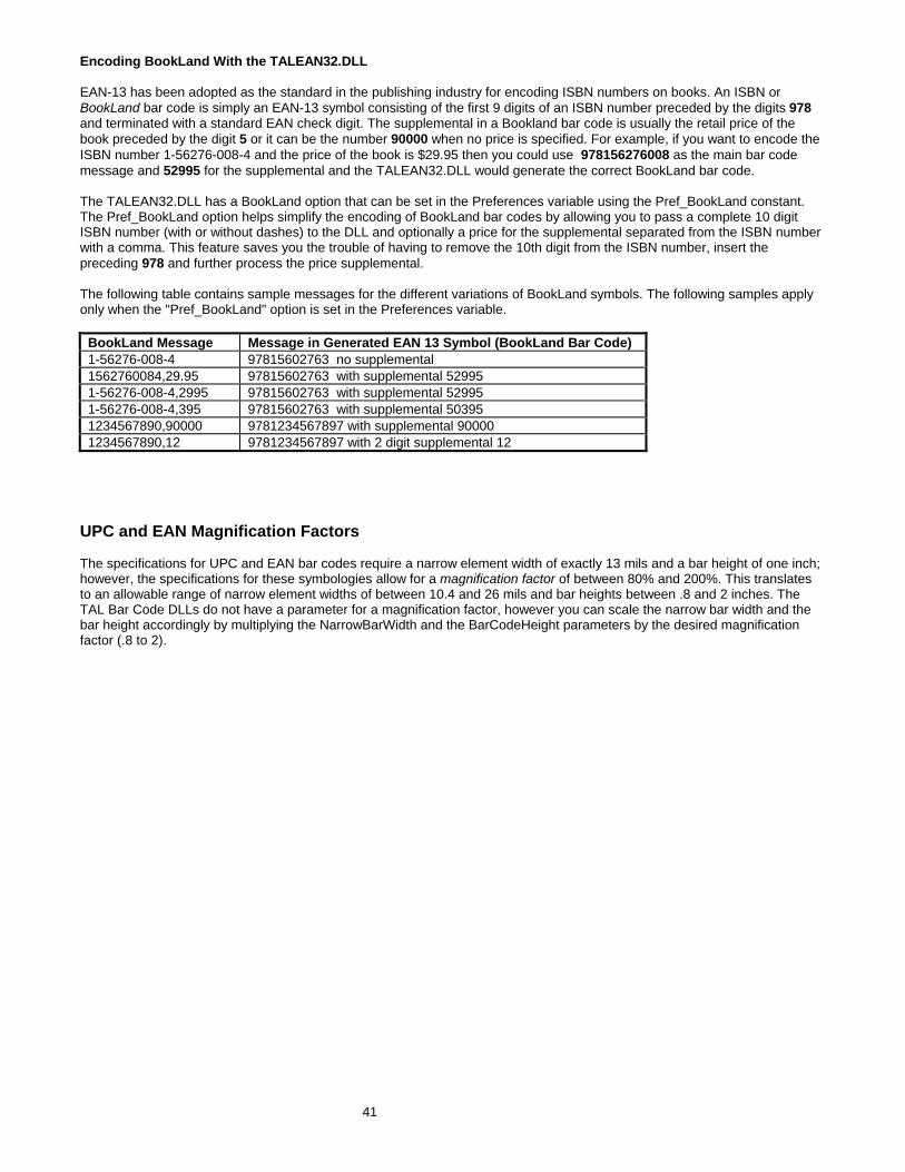
41
Encoding BookLand With the TALEAN32.DLL EAN-13 has been adopted as the standard in the publishing industry for encoding ISBN numbers on books. An ISBN or BookLand bar code is simply an EAN-13 symbol consisting of the first 9 digits of an ISBN number preceded by the digits 978 and terminated with a standard EAN check digit. The supplemental in a Bookland bar code is usually the retail price of the book preceded by the digit 5 or it can be the number 90000 when no price is specified. For example, if you want to encode the ISBN number 1-56276-008-4 and the price of the book is $29.95 then you could use 978156276008 as the main bar code message and 52995 for the supplemental and the TALEAN32.DLL would generate the correct BookLand bar code. The TALEAN32.DLL has a BookLand option that can be set in the Preferences variable using the Pref_BookLand constant. The Pref_BookLand option helps simplify the encoding of BookLand bar codes by allowing you to pass a complete 10 digit ISBN number (with or without dashes) to the DLL and optionally a price for the supplemental separated from the ISBN number with a comma. This feature saves you the trouble of having to remove the 10th digit from the ISBN number, insert the preceding 978 and further process the price supplemental. The following table contains sample messages for the different variations of BookLand symbols. The following samples apply only when the "Pref_BookLand" option is set in the Preferences variable.
BookLand Message Message in Generated EAN 13 Symbol (BookLand Bar Code) 1-56276-008-4 97815602763 no supplemental 1562760084,29.95 97815602763 with supplemental 52995 1-56276-008-4,2995 97815602763 with supplemental 52995 1-56276-008-4,395 97815602763 with supplemental 50395 1234567890,90000 9781234567897 with supplemental 90000 1234567890,12 9781234567897 with 2 digit supplemental 12
UPC and EAN Magnification Factors The specifications for UPC and EAN bar codes require a narrow element width of exactly 13 mils and a bar height of one inch; however, the specifications for these symbologies allow for a magnification factor of between 80% and 200%. This translates to an allowable range of narrow element widths of between 10.4 and 26 mils and bar heights between .8 and 2 inches. The TAL Bar Code DLLs do not have a parameter for a magnification factor, however you can scale the narrow bar width and the bar height accordingly by multiplying the NarrowBarWidth and the BarCodeHeight parameters by the desired magnification factor (.8 to 2).
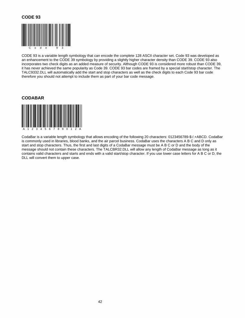
CODE 93
C o d e 9 3 CODE 93 is a variable length symbology that can encode the complete 128 ASCII character set. Code 93 was developed as an enhancement to the CODE 39 symbology by providing a slightly higher character density than CODE 39. CODE 93 also incorporates two check digits as an added measure of security. Although CODE 93 is considered more robust than CODE 39, it has never achieved the same popularity as Code 39. CODE 93 bar codes are framed by a special start/stop character. The TALC9332.DLL will automatically add the start and stop characters as well as the check digits to each Code 93 bar code therefore you should not attempt to include them as part of your bar code message. CODABAR
A 1 2 3 4 5 6 7 8 9 0 1 2 A CodaBar is a variable length symbology that allows encoding of the following 20 characters: 0123456789-$:/.+ABCD. CodaBar is commonly used in libraries, blood banks, and the air parcel business. CodaBar uses the characters A B C and D only as start and stop characters. Thus, the first and last digits of a CodaBar message must be A B C or D and the body of the message should not contain these characters. The TALCBR32.DLL will allow any length of CodaBar message as long as it contains valid characters and starts and ends with a valid start/stop character. If you use lower case letters for A B C or D, the DLL will convert them to upper case.
42

INTERLEAVED 2 OF 5 (ITF)
1 2 3 4 5 6 7 8 9 0 1 2 Interleaved 2 of 5 is a high density variable length numeric only symbology that encodes digit pairs in an interleaved manner. The odd position digits are encoded in the bars and the even position digits are encoded in the spaces. Because of this, Interleaved 2 of 5 bar codes must consist of an even number of digits. Also, because partial scans of I 2 of 5 bar codes have a slight chance of being decoded as a valid (but shorter) bar code, readers are usually set to read a fixed (even) number of digits when reading Interleaved 2 of 5 symbols. The number of digits is usually pre-defined for a particular application and all readers used in the application are programmed to only accept ITF bar codes of the chosen length. Shorter data can be left padded with zeros to fit the proper length. The TALITF32.DLL will only accept numeric digits for Interleaved 2 of 5 bar codes. If an odd number of digits is entered, the DLL will Left-Pad one zero to the number entered. Interleaved 2 of 5 optionally allows for a weighted modulo 10 check character for special situations where data security is important. To enable the Interleaved 2 of 5 check character, use the Preferences option Pref_OptionalCheckDigit1 in Preferences variable. When this option is enabled, the DLL will automatically calculate and append the proper check character to all Interleaved 2 of 5 symbols. MSI-PLESSEY
1 2 3 4 5 6 7 8 9 0 MSI-PLESSEY is a variable length, numeric only, symbology. The symbology is one of the earliest bar code symbologies ever developed and is based on a four bit binary number scheme. Each symbol is framed by a start and a stop pattern and contains a check character that is calculated from the values of each of the encoded data digits. MSI-Plessey is rarely used in anything other than grocery store shelf marking applications. In fact most modern bar code readers do not provide support for reading MSI-Plessey symbols.
43
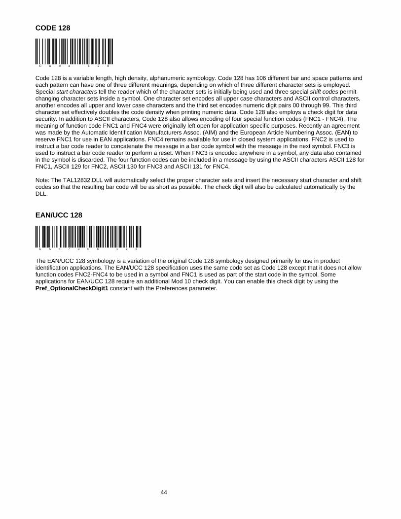
CODE 128
C o d e 1 2 8 Code 128 is a variable length, high density, alphanumeric symbology. Code 128 has 106 different bar and space patterns and each pattern can have one of three different meanings, depending on which of three different character sets is employed. Special start characters tell the reader which of the character sets is initially being used and three special shift codes permit changing character sets inside a symbol. One character set encodes all upper case characters and ASCII control characters, another encodes all upper and lower case characters and the third set encodes numeric digit pairs 00 through 99. This third character set effectively doubles the code density when printing numeric data. Code 128 also employs a check digit for data security. In addition to ASCII characters, Code 128 also allows encoding of four special function codes (FNC1 - FNC4). The meaning of function code FNC1 and FNC4 were originally left open for application specific purposes. Recently an agreement was made by the Automatic Identification Manufacturers Assoc. (AIM) and the European Article Numbering Assoc. (EAN) to reserve FNC1 for use in EAN applications. FNC4 remains available for use in closed system applications. FNC2 is used to instruct a bar code reader to concatenate the message in a bar code symbol with the message in the next symbol. FNC3 is used to instruct a bar code reader to perform a reset. When FNC3 is encoded anywhere in a symbol, any data also contained in the symbol is discarded. The four function codes can be included in a message by using the ASCII characters ASCII 128 for FNC1, ASCII 129 for FNC2, ASCII 130 for FNC3 and ASCII 131 for FNC4. Note: The TAL12832.DLL will automatically select the proper character sets and insert the necessary start character and shift codes so that the resulting bar code will be as short as possible. The check digit will also be calculated automatically by the DLL. EAN/UCC 128
E A N / U C C 1 2 8 The EAN/UCC 128 symbology is a variation of the original Code 128 symbology designed primarily for use in product identification applications. The EAN/UCC 128 specification uses the same code set as Code 128 except that it does not allow function codes FNC2-FNC4 to be used in a symbol and FNC1 is used as part of the start code in the symbol. Some applications for EAN/UCC 128 require an additional Mod 10 check digit. You can enable this check digit by using the Pref_OptionalCheckDigit1 constant with the Preferences parameter.
44

POSTNET
POSTNET (POSTal Numeric Encoding Technique) is a 5, 9 or 11 digit numeric only bar code symbology used by the US Postal Service to encode ZIP Code information for automatic mail sorting. The bar code may represent a five digit ZIP Code (32 bars), a nine digit ZIP + 4 code (52 bars) or an eleven digit Delivery Point code (62 bars). POSTNET is unlike other bar codes because data is encoded in the height of the bars instead of in the widths of the bars and spaces. Most commercially available bar code readers cannot decode POSTNET. This symbology was chosen by the Postal Service mainly because it is extremely easy to print on almost any type of printer. POSTNET is a fixed dimension symbology meaning that the height, width and spacing of all bars must fit within tight tolerances. The TALZIP32.DLL will only create POSTNET bar codes that follow the guidelines published by the Postal Service. The DLL does not allow direct control over the size of POSTNET bar codes. In other words the NarrowBarWidth, BarWidthReduction and the BarCodeHeight parameters are ignored. Since POSTNET does not support any human readable text, quietzones, bearer bars or optional check digits, all parameters in the TALBarCode type structure relating to these features are also ignored. The TALZIP32.DLL will ignore non-numeric data in any POSTNET bar code message. For example, if you enter "Chicago, IL 60601-3222" for a POSTNET bar code message, the DLL will still create a correct bar code. This feature allows you to pass an address line from another Windows program to the DLL without having to parse out the Zip code. Postal FIM Patterns FIM or "Facing Identification Mark" patterns are another type of postal bar code used in automated mail processing by the US Postal Service. FIM patterns are used for automatic facing and canceling of mail that does not contain a stamp or meter imprint (business reply mail, penalty mail, etc.). They also provide a means of separating business and courtesy reply mail from other letters. Three FIM patterns are currently in use. FIM-A is used on courtesy reply mail that has been preprinted with PostNET bar codes. FIM-B is used on business reply, penalty and franked (government) mail that is not preprinted with PostNET bar codes. FIM-C is used on business reply, penalty and franked mail that has been preprinted with PostNET bar codes. FIM patterns are placed in the upper right corner along the top edge and two inches in from the right edge of letters and cards. For more information about all postal bar codes contact your local post office. Since postal FIM patterns are always the same, instead of providing a DLL to create FIM patterns, the three FIM patterns have been provided with the PostNET DLL in the form of three Aldus Placeable Metafiles on the DLL disk. The three files are named FIM-A.WMF, FIM-B.WMF and FIM-C.WMF.
45

PDF417
PDF417 is a high-density 2-dimensional bar code symbology that essentially consists of a stacked set of smaller bar codes. The symbology is capable of encoding the entire (255 character) ASCII character set. PDF stands for "Portable Data File" because it can encode as many as 2710 data characters in a single bar code. The complete specification for PDF417 provides many encoding options including data compaction options, error detection and correction options, and variable size and aspect ratio symbols. The symbology was published by Symbol Technologies, Inc. to fulfill the need for higher density bar codes. The low level structure of a PDF417 symbol consists of an array of code words (small bar and space patterns) that are grouped together and stacked on top of each other to produce the complete printed symbol. An individual code word consists of a bar and space pattern 17 modules wide. The user may specify the module width, the module height, and the overall aspect ratio (overall height to width ratio) for the complete symbol. A complete PDF417 symbol consists of at least 3 rows of up to 30 code words and may contain up to 90 code word rows per symbol with a maximum of 928 code words per symbol. Shown below is the basic structure of a typical PDF417 bar code.
StartPattern
Left RowIndicator
Right RowIndicator
StopPatternData Codewords
Row 0....
Row 6 The code words in a PDF417 symbol are generated using one of three data compaction modes currently defined in the symbology specifications. This allows more than one character to be encoded into a single data code word. Because different data compaction algorithms may be used, it is possible for different printed symbols to be created from the same input data. The symbology also allows for varying degrees of data security or error correction and detection. Nine different error correction levels are available with each higher level adding additional overhead to the printed symbol. The TALPDF32.DLL allows complete control over all optional features of PDF417.
46

47
PDF417 Bar Code Dimensions A PDF417 bar code symbol consists of multiple rows of bar code data encoded in units called code words. Each symbol can contain from 3 to 90 rows and each row consists of a Start/Stop pattern and from 3 to 32 code words (1 to 30 code words for data and 2 for Right and Left Row Indicators). The smallest element in a PDF417 symbol is called a module. Each code word consists a unique pattern of 4 bars and 4 spaces each with a width of up to 6 modules within a total width of 17 modules per code word. (This is where the "417" comes from in the name PDF417 - 4 bars within 17 modules.) Because the number of code words in a row and the total number of rows in a symbol are variable quantities, the three primary dimensions used to define the size of a PDF417 bar code are the Module Width, the Module Height, and the overall Aspect Ratio. The Module Height and Width values define the height and width of the smallest element in the PDF417 symbol and the Aspect Ratio specifies the overall shape of the symbol. The best choice for the Module Width dimension depends partly on the resolution of your bar code reading equipment and also on the resolution of the printer being used to produce the bar code. The specification for PDF417 recommends that the Module Width should fall in a range between 10 and 30 mils. The smallest allowable module width defined in the symbology specification is 6.56 mils. (This translates to 2 printer dots when printing to a 300 DPI laser printer.) The best way to determine the ideal Module Width for your application is to actually print out a sample bar code using several different values and try reading each one with your scanning equipment. Again, you should choose the value that produces bar codes with the best read rate. The recommended value for the Module Height is approximately three times the value for the Module Width however the symbol specifications allow for module heights as small as 10 mils (3 printer dots on a 300 DPI laser printer).

48
PDF417 Aspect Ratio The Aspect Ratio determines the overall shape of the PDF417 symbol and is defined as the overall height to width ratio. Higher values for the Aspect Ratio (greater than 1) produce tall, thin PDF417 bar codes and small values (greater than zero and less than 1) produce short, wide bar codes. A value of 1 should produce approximately square bar codes. Because each row of data in a PDF417 symbol contains 2 additional code words of overhead (right and left row indicators) as well as start and stop patterns, tall and thin bar codes with lots of rows (high aspect ratios) will be larger in total area and contain more overhead than short wide bar codes (low aspect ratios). On the other hand, short wide bar codes (low aspect ratios) may be difficult to read due to scanner width limitations. NOTE: Because of the basic structure of a PDF417 symbol, you will probably not be able to produce a bar code with the exact Aspect Ratio that you specify. The TAL Bar Code DLL for PDF417 will automatically generate a bar code with the closest match to the Aspect Ratio that you specify within the limits of the symbol specification. For any given PDF417 bar code symbol there are only a small number of possible aspect ratios that are physically possible. The TAL Bar Code DLL for PDF417 also provides more detailed control over the size and shape of a PDF417 symbol by allowing you to specify the maximum number of rows and a maximum number of data code word columns in a symbol. You can also cause the DLL to produce a version of PDF417 called Truncated PDF417 that removes the Right Row Indicator code words and the stop pattern on the right hand side of the symbol thus reducing the total size of a PDF417 symbol.

49
PDF417 Data Compaction Modes There are three pre-established data compaction modes for the PDF417 symbology. The three modes are listed below: 1. Extended Alphanumeric Compaction (EXC) mode. This mode supports the encoding of all printable ASCII characters and can compress approximately 2 characters per code word. 2. Binary/ASCII Plus mode. Binary mode supports encoding of the entire ASCII character set. Binary mode can compress approximately 1.2 characters per code word. 3. Numeric Compaction mode. Numeric mode can encode only the numeric characters 0 through 9 and can achieve data compression of approx. 3 characters per code word. One or more modes can be used in a single PDF417 symbol by using special shift and latch code words to switch between modes within the symbol. The TALPDF32.DLL gives you the option to select any of the three standard data compaction modes as well as two Auto modes that automatically generate the smallest number of code words (and thus the smallest symbol) by intelligently switching between the three standard modes. The first of the 2 Auto modes provided by the TALPDF32.DLL is called Auto (EXC/Binary/Numeric). This mode allows full switching between the three standard data compaction modes and provides the maximum data compression possible. The second mode, Auto (EXC/Binary), is similar to the first except that it does not allow switching to Numeric mode in a symbol. The only reason for this mode is to provide support for a small number of early PDF417 readers that did not have the capability to decode Numeric mode encoded data. PDF417 Error Detection and Correction One of PDF417's primary features is error detection and correction or data security. Each PDF417 symbol has 2 code words for error detection. (Similar to a check digit in standard bar code symbols.) The error correction capacity may be selected based on the needs of a specific application. Error correction compensates for label defects and misdecodes. There are essentially 2 types of errors that can occur in a bar code symbol, Erasures and Misdecodes. Erasures are missing or undecodable code words and misdecodes are errors that cause the reader to interpret a particular code word incorrectly. Nine error correction levels numbered 0 through 8 are available in the symbol specification. Each higher security level allows for a higher number of erasures and misdecodes to be recovered from. (Since it requires 2 code words to recover from a misdecode, one to detect the error and one to correct for it, a given security level can support half the number of misdecodes that it can undecoded or missing code words.)

Since error correction and detection is encoded into additional code words, each higher security level adds additional overhead to a printed symbol. Higher security levels reduce the maximum number of data characters that can be encoded in a symbol and also increase the size of a printed symbol. (A single PDF417 symbol can contain a maximum of 928 total code words for data and error correction combined.) The relationship between security level, error correction capacity and the number of additional code words or overhead required for a given security level is as follows: Error Correction Maximum Limit of Allowable Symbol Overhead (Number Level Erasures + (2 x Misdecodes) of Additional Code words) 0 0 2 1 2 4 2 6 8 3 14 16 4 30 32 5 62 64 6 126 128 7 254 256 8 510 512 Truncated PDF417 Symbols In an effort to further reduce the size of a PDF417 symbol, the designers of the symbology allowed for a variation of PDF417 called Truncated PDF417. A truncated PDF417 symbol is almost identical to a standard PDF417 symbol except that the right row indicator code words and the right hand stop pattern are omitted and replaced with a narrow bar one module wide. Truncated PDF417 symbol:
StartPattern
Left RowIndicator Data Codewords
Row 0....
Row 6
50

51
PDF417 Options The three main sets of options available are Data Compaction Mode, Security Level and Size Control Parameters. The five Data Compaction modes available in The TALPDF32.DLL are AUTO (EXC/Binary/Numeric), AUTO (EXC/Binary), EXC, Binary and Numeric. For almost all applications the Data Compaction option should be left set to AUTO(EXC/Binary/Numeric). This will provide the maximum data compaction possible for any given bar code message. The other four data compaction options are provided to allow experimenting with the other compaction modes. The PDFSecurityLevel options allow you to select a specific PDF417 error correction level from 0 to 8. You can also have the TALPDF32.DLL automatically select a security level based on a percentage of total symbol area to be used for error correction. If you pass the value 9 (Auto) for the PDFSecurityLevel parameter, you can then pass a percentage value in the PDFPctOverhead variable (from 0% to 99%). The "Auto" PDFSecurityLevel mode is probably the best way to specify a security level because it guarantees that you will not waste symbol real estate with more error correction overhead than is necessary for small messages. It also insures that enough error correction will be generated for larger messages. (A small message only needs a small amount of error correction capacity while a larger message needs more.) If you pass the value of zero for the PDFPctOverhead parameter, the default percentage of 11% will be used. Three other parameters that control the size of a PDF417 symbol are the PDFMaxRows and PDFMaxCols parameters and a Preferences option to enable printing of Truncated PDF417 symbols. The default maximum number of data rows and columns are the maximum values allowable in the PDF417 symbol specification (i.e. 30 rows and 90 Columns) . If you specify smaller values for these parameters, you are essentially defining an upper limit to the overall height or width of all generated PDF symbols. For example, suppose you need to generate a PDF symbol that absolutely must be no wider than two inches and you chose 10 mils for the module width. Because there are 17 modules in a code word and there are 69 modules of overhead per row, (start/stop patterns and right/left row indicators) the maximum number of code word columns allowable in a 2 inch wide symbol can be calculated using the formula:
10mils x [(17 x MaxCols) + 69]<=2000 mils (2 inches) If we solve the equation above we obtain the value of 7 for the Maximum number of code word columns (MaxCols). Thus, if we set the Maximum Number of Data Columns parameter to 7, the TALPDF32.DLL will only produce PDF417 symbols that are less than 2 inches wide. The remaining size control parameter, Create Truncated PDF417 Symbols, causes the TALPDF32.DLL to create the truncated version PDF417 that removes the right row indicator and the right hand stop pattern from the symbol. When creating Truncated PDF417 symbols, there are only 35 overhead modules per row instead of the normal 69 overhead modules. This option can be selected by using the Pref_TruncatedPDF constant with the Preferences variable in the TALPDFBarCode type structure.

Aztec Code Aztec Code is a high density 2 dimensional matrix style bar code Symbology that can encode up to 3750 characters from the entire 256 byte ASCII character set. The symbol is built on a square grid with a bull's-eye pattern at its center. Data is encoded in a series of "layers" that circle around the bull's-eye pattern. Each additional layer completely surrounds the previous layer thus causing the symbol to grow in size as more data is encoded yet the symbol remains square. Aztec's primary features include: a wide range of sizes allowing both small and large messages to be encoded, orientation independent scanning and a user selectable error correction mechanism. The smallest element in an Aztec symbol is called a "module" (i.e. a square dot). The module size and the amount of error correction are the only "dimensions" that can be specified for an Aztec symbol and both are user selectable. It is recommended that the module size should range between 15 to 30 mils in order to be readable by most of the scanners that are currently available. The overall size of an Aztec symbol is dependent on the module size, the total amount of encoded data and also on the level of error correction capacity chosen by the user. The smallest Aztec symbol is 15 modules square and can encode up to 14 digits with 40% error correction. The largest symbol is 151 modules square and can encode 3000 characters or 3750 numeric digits with 25% error correction. There are three types of Aztec symbols, a "Compact" symbol, a "Full Range" symbol and a "Menu" symbol. Compact symbols have a smaller bull's-eye pattern and are limited in their overall size to having up to four "layers" of data surrounding the bull's-eye pattern. Full Range symbols have a larger bull's-eye pattern and can have up to 32 layers of data surrounding the bull's-eye. Do not confuse "Layers" with modules. A layer actually is made up of two stacked modules resembling a domino with each domino laid out around the bull's-eye pattern so that the long edge of the domino points away from the center of the symbol. Menu symbols are a special type of Aztec bar code that are typically used by scanner manufacturers to create bar codes that contain commands for enabling and disabling features in a bar code reader. Menu symbols can be either Compact or Full Range symbols and are only useful if you know the commands that a particular reader will recognize.
Compact Symbol Full Range Symbol
52

Data Matrix
Data Matrix is a high density 2 dimensional matrix style bar code symbology that can encode up to 3116 characters from the entire 256 byte ASCII character set. The symbol is built on a square grid arranged with a finder pattern around the perimeter of the bar code symbol. There are two types of Data Matrix symbols each using a different error checking and correction scheme (ECC). The different types of Data Matrix symbols are identified using the terminology "ECC" followed by a number representing the type of error correction that is used by the encoding software. ECC 000 to ECC 140 are the original type of Data Matrix symbols and are now considered obsolete. The newest version of Data Matrix is called ECC 200 and is recommended for all new Data Matrix applications. The ECC 200 version of Data Matrix uses a much more efficient algorithm for encoding data in a symbol as well as an advanced error checking and correction scheme. The TAL Data Matrix bar code DLL fully supports all variations of the Data Matrix symbology however the author of the original symbology specification (CI Matrix Co.) highly recommends that ECC 000 - ECC 140 be used only where absolutely necessary. ECC 000 - ECC 140 Data Matrix symbols designated by the terms ECC 000 to ECC 140 are the original type of Data Matrix symbol that uses a convolutional error correction scheme. There are actually five levels of error correction available for this type of Data Matrix symbol with each higher level of error correction designated as follows. ECC 000 - Provides no error correction ECC 050 - Provides error correction for damage of up to 2.8% of the printed symbol. ECC 080 - Provides error correction for damage of up to 5.5 % of the printed symbol. ECC 100 - Provides error correction for damage of up to 12.6% of the printed symbol. ECC 140. - Provides error correction for damage of up to 25% of the printed symbol. For all five ECC levels ECC 000 - ECC 140 there is also a user selectable option for a "Data Format" which defines the type of data that may be encoded in a Data Matrix symbol. The available formats are listed below: Format ID Allowable Data In The Bar Code Message 1 Numeric digits 0 to 9 and the space character 2 Uppercase alpha A-Z and the space character 3 Upper case alphanumeric A-Z, 0-9 and the space character 4 A-Z, 0-9, space, minus, period, comma & forward slash (/) 5 7-bit ASCII - all ASCII characters between ASCII 0 to ASCII 127 6 8-bit ASCII - all ASCII characters between ASCII 0 to ASCII 255
53

54
ECC200 ECC 200 is the latest and most advanced version of Data Matrix and is therefore strongly recommended for use in all new Data Matrix applications. ECC 200 uses a Reed-Solomon error correction algorithm along with a code set switching mechanism that is much more efficient at packing data into a symbol than any of the earlier encoding schemes (ECC 000 - ECC 140). ECC 200 is capable of encoding the entire 8-bit ASCII character set in a highly efficient manner and therefore does not provide for or require any Data Format options. In addition to encoding 8 bit ASCII data, ECC 200 also allows for a special function code called "FNC1" as well as special indicators for features like "Structured Append" and "Extended Channel Interpretation". Structured append is a means for generating multiple bar codes containing a much larger data message than can be encoded into a single symbol. With structured append, each bar code contains a portion of a larger data message along with a number that identifies the portion of the message contained in the symbol. When a bar code reader scans a symbol that is part of a sequence, it will not transmit the data until all symbols in a sequence have been read. It does not matter what order the bar codes are read in - the reader will correctly build the complete message. Extended Channel Interpretation is a mechanism for creating user definable data encoding schemes. For example, suppose you wanted to replace the standard ASCII character set with a different character set (a foreign language character set for example), you could use the Extended Channel Interpretation feature in ECC 200 to indicate that the message encoded in a symbol conforms to the new interpretation. Notes: To encode data to conform to specific industry standard it needs to be authorized by AIM International. The TAL Data Matrix DLL supports all features of the ECC 200 version of Data Matrix. Because ECC 200 supports the entire 8 bit ASCII character set and therefore cannot use ASCII character values to represent special features (like FNC1), the DLL provides two methods for interpreting the input data message. The DLL has an option called "Standard_ASCII " that determines how the input data message is interpreted. If the "Standard_ASCII " constant is ORed with the Preferences variable, then all input data to DLL is assumed to not contain any special function codes like FNC1 or Extended Channel Interpretation codes. For most normal applications this option would normally be used. If the "Standard_ASCII" constant is not ORed with the Preferences variable, then the tilde character (~) can be used in the input message as an indicator that the character(s) following the tilde are to be interpreted with a special meaning as outlined below. To encode a tilde (~) use the string: ~~ (i.e. two tilde characters). If no tilde characters or Nuls (ASCII 0) are present in the input message, then enabling the "Standard_ASCII " option has no effect on the resulting bar code symbol.

55
Data Matrix Tilde Control Codes ~X (a tilde character followed by any upper case alpha character) is used as a shift character for inserting control codes (characters with ASCII values 0 to 26) into a bar code message. For example, ~@ = NUL, ~A = ASCII 1,~G = BEL (ASCII 7), ~M = ASCII 13 (carriage return). If you need to insert ASCII control codes into a message, take the ASCII value for the control code (1-26) and find the corresponding letter in the alphabet and precede it with a tilde. i.e. The ASCII value for a carriage return character is ASCII 13 and the thirteenth letter of the alphabet is "M" therefore to insert a carriage return in a bar code message, you would use "~M". Note: You can also pass control codes directly to the DLL without having to use the ~ before an alpha character. For example you could use either an ASCII 13 character or the sequence ~M to represent a carriage return. ~1 is used to represent the FNC1 code and is followed by normal data. To encode data to conform to specific industry standards as authorized by AIM International, a FNC1 character shall appear in the first or second symbol character position (or fifth or sixth data position of the first symbol of structured append). FNC1 encoded in any other position is used as a field separator and shall be transmitted as a GS control character (ASCII value 29). Notes: To encode data to conform to specific industry standard, it needs to be authorized by AIM International. Contact AIM International at Tel: 703-391-7621 or email: [email protected] If the FNC1 code is used in the second character position, the input data before '~1' must be, between 'A' and 'Z', or between 'a' and 'z' or 2-digits between '01' and '99'. ~2 is used to represent Structured Append and must be followed by a three 3-digit number between 1 and 255 representing the symbol sequence as well as a file identifier of six numeric digits. The file identifier is used to uniquely identify a sequence so that only logically linked sequences are processed as part of the same sequence. The symbol sequence identifier is a number between 1 and 255 that indicates the position of the symbol within a sequence of up to 16 symbols. The sequence identifier actually contains two four-bit values representing the sequence number and the total number of symbols in the sequence (i.e. m of n where m is the sequence number and n is the total number of symbols). The upper four bits of this value represent the position of the particular symbol as the binary value of (m-1) and the lower order four bits identify the total number of symbols to be concatenated as the binary value of (17-n). For example, symbol 3 in a sequence of 7 symbols with file ID: 001015 is represented by ~2042001015. The number 042 is derived as follows: 3-1=2 which equals 0010 when represented as a 4 bit binary number. 17-7=10 which equals 1010 when represented as a 4 bit binary number. After concatenating the two 4 bit binary values we end up with 00101010 which equals 42 in decimal. ~3 Indicates that a message is to be used for reader programming purposes and is followed by normal data. This feature is only useful if you know the specific programming commands for your bar code reader.

56
~5 and ~6 indicates that the data will contain an abbreviated format header and trailer followed by normal data. The ~5 or ~6 must appear as the first two characters in a message and must not be used in conjunction with structured append. Data Matrix provides a means of abbreviating an industry specific header and trailer in one symbol character. This feature exists to reduce the number of characters needed to encode data using certain structured formats. If a ~5 is used as the first two characters of a message, the header [)> + ASCII 30 + 05 + ASCII 29 will be transmitted by the reader before the data in the message and the trailer ASCII 30 + ASCII 4 will be transmitted following the data. Likewise, if a ~6 is used as the first two characters of a message, the header [)>+ ASCII 30 + 06 + ASCII 29 will be transmitted by the reader before the data in the message and the trailer ASCII 30 + ASCII 4 will be transmitted following the data. ~7NNNNNN is used to indicate Extended Channel NNNNNN where NNNNNN is 6-digit EC value (000000 - 999999). e.g. Extended Channel 9 is represented by ~7000009 ~dNNN creates ASCII decimal value NNN for a codeword (must be 3 digits). Please refer to the official Data Matrix symbology specification for details on the meanings of all codeword values for ECC 200. Contact AIM International at Tel: 703-391-7621 or email: [email protected]

57
Calling the TAL Aztec and Data Matrix bar code DLLs The TAL bar code DLLs for Aztec and Data Matrix use the same type structure (the TALMatrixCode structure) for all input parameters. Almost all of the parameters in the TALMatrixCode structure are the same as the parameters in a standard TALBarCode structure except for a few small differences and a few additional parameters specific to the matrix type bar code symbologies. The MessageBuffer parameter is defined as a string 3832 bytes in length instead of 100 bytes. Instead of a "NarrowBarWidth" parameter, the TALMatrixCode structure has a "ModuleSize" parameter that defines both the height and width of the square dots that make up a matrix style bar code. Because all matrix style bar codes use some form of "Error Checking and Correction" (ECC) mechanism, a parameter called "ECCValue" has been included in the structure definition. This parameter is used to specify any ECC options supported by a particular symbology. A "DataFormat" parameter has been included in the structure. This parameter is only used when generating Data Matrix bar codes. Visual Basic Type declaration for TALMatrixCode data type Type TALMatrixCode MessageLength As Long ' Length of the input data message MessageBuffer As String * 3832 ' Buffer for the input data message CommentLength As Long ' Length of the comment CommentBuffer As String * 100 ' Buffer for the comment ModuleSize As Long ' Module height / width in units of .01mm BarWidthReduction As Long ' Bar width reduction or gain value ranging from -99% to 99% ECCValue As Long ' Error correction value. See notes below DataFormat As Long ' Data Format value for Data Matrix ECC 000 - ECC 140 FGColor As Long ' Foreground RGB color value BGColor As Long ' Background RGB color value MyFontName As String * 32 ' Font name for the comment MyFontSize As Long ' Font size in points TextColor As Long ' RGB color for the comment text Orientation As Long ' Orientation - 0 to 3 representing 90 degree increments Preferences As Long ' Bit values as described for each symbology HorizontalDPI As Long ' Printer DPI values - used when AdjustToPrinterDPI VerticleDPI As Long ' is enabled in preferences OutputOption As Long ' 0=Clipboard, 1=SaveToFile, 2=MetafilePict, 3=hDC OutputFilename As String * 260 ' ASCIIZ filename (null terminated) OutputhDC As Long ' Output device context (when outputting to hDC) XPosInInches As Single ' X page position (when outputting to hDC) YPosInInches As Single ' Y page position (when outputting to hDC) Reserved As Long End Type
58
Visual Basic DLL Function Declarations for Aztec and Data Matrix DLLs Declare Function TALAZTEC Lib "TALAZT32.DLL" (BC As TALMatrixCode, MetaPict As MetafilePict) As Long Declare Function TALDMX Lib "TALDM32.DLL" (BC As TALMatrixCode, MetaPict As MetafilePict) As Long Important Note: The Data Matrix TALDM32.DLL file requires that a second DLL file named ENCODE32.DLL be installed on the users system. When you distribute your application that uses the TALDM32.DLL file, you must also include the dependent ENCODE32.DLL file. As with all DLL files, it is recommended that you install the DLLs in either the Windows/System32 directory or in the directory where the calling application has been installed.

59
Sample C/C++ DLL Function Declaration for Aztec and Data Matrix DLLs extern "C" { int WINAPI TALAZTEC (TALMatrixCode * barcode, METAFILEPICT * metapict); int WINAPI TALDMX (TALMatrixCode * barcode, METAFILEPICT * metapict); TALAZTEC TALAZT32.DLL Aztec Code TALDMX TALDM32.DLL Data Matrix }; C/C++ TALMatrixCode Type Structure The following is a 32 Bit C/C++ declaration for the TALMatrixCode data type with comments indicating the purpose of each individual data member. typedef struct tag TALMatrixCode { long messageLength; // Length of message to be encoded char messageBuffer[3832]; // Message buffer long commentLength; // Length of comment char commentBuffer[100]; // Comment buffer long moduleSize; // module height & width in units of .01 mm long barWidthReduction; // Percent of narrowBarWidth long ECCValue // ECC value. See notes for the different symbologies long DataFormat // Data Format for Data Matrix ECC 000 - ECC 140 COLORREF fgColor; // Foreground Color COLORREF bgColor; // Background Color char fontName[32]; // Font name for human readable text long fontSize; // Font size in points COLORREF textColor; // Text color - RGB color value long orientation; // Rotation 0 - 3 for 0, 90 , 180, 270 degrees long preferences; // Bit values as described below long horizontalDPI; // Printer DPI values used when AdjustToPrinterDPI long verticleDPI; // flag is set in Preferences (see notes below) long outputOption; // 0=Clipboard, 1=File, 2=MetafilePict, 3=hDC char outputFilename[260]; // ASCIIZ filename when saving to disk HDC outputDC; // Output device context when outputting to hDC float XPosInInches; // X page position (when outputting to hDC) float YPosInInches; // Y page position (when outputting to hDC) long reserved; // Reserved for future use } TALMatrixCode;

60
Aztec Code Error Correction Values Aztec Code supports the ability to specify the amount of error checking and correction to be incorporated into a printed symbol. Several methods can be used based on either a percentage of symbol area or as the total number of codeword "layers" that a symbol should contain. (A layer in Aztec is a two module high rectangle surrounding the center finder pattern.) You specify the amount of error correction to the TALAztec DLL by passing a value in the ECCValue parameter in the TALMatrixCode data structure. The values that you can pass for the ECCValue parameter are as follows: 0 Specifying zero causes the DLL to use the default error correction, which will consume roughly 23% of the total symbol area. 1 - 99 The values from 1 to 99 represent the percentage of the total symbol area that you would like to reserve for error correction. The higher the percentage, the larger your Aztec symbols will be. 101 - 104 If you specify a value between 101 and 104, the TALAzt32.DLL will generate a compact symbol with 1 to 4 layers (101 means to generate a 1 layer compact symbol, 102 generates a 2 layer compact symbol, etc.) 201 - 232 If you specify a value between 201 and 232, the TALAzt32.DLL will generate a Full Range symbol with 1 to 32 layers. If you specify values of 101 to 104 or 201 to 232, you are directly specifying the total number of data layers therefore all of your Aztec symbols will be the same size. If all of the layers in the symbol are not used for data, any remaining empty layers will be used for error correction. If the message that you are trying to encode requires more layers than the number of layers that you specify, the DLL will return an error value of 2 (i.e. Invalid Message Length). For most normal applications, you should use the default error correction by specifying zero. If you specify a value outside the allowable range (i.e. 0 - 99, 101 - 104 or 201 - 232), the DLL will use the default error correction value of zero.

61
Data Matrix Error Correction and Data Format Values With Data Matrix bar codes, there are currently six different types of symbol where the difference between each type is the amount of error checking and correction. When generating Data Matrix symbols of types ECC 000 to ECC 140 and ECC 200, the ECC number is passed to the Data Matrix DLL in the parameter ECCValue. For example to specify ECC 200, you would pass the value 200 to the DLL in the parameter "ECCValue". ECC 000 - Provides no error correction ECC 050 - Provides error correction for damage of up to 2.8% of the printed symbol. ECC 080 - Provides error correction for damage of up to 5.5 % of the printed symbol. ECC 100 - Provides error correction for damage of up to 12.6% of the printed symbol. ECC 140 - Provides error correction for damage of up to 25% of the printed symbol. ECC 200 - Uses a Reed Solomon error correction algorithm that will automatically provide a varying degree of error correction
for damage ranging from a minimum of roughly 20% to greater than 60% damage depending on the amount of data encoded.
For the five ECC levels ECC 000 - ECC 140 there is also a user selectable option for a "Data Format" which defines the type of data that may be encoded in a Data Matrix symbol. This parameter is passed to the Data Matrix DLL in the parameter DataFormat The available formats are listed below: Format ID Allowable Data 1 Numeric digits 0 to 9 and the space character 2 Uppercase alpha A-Z and the space character 3 Upper case alphanumeric A-Z, 0-9 and the space character 4 A-Z, 0-9, space, minus, period, comma & forward slash (/) 5 7-bit ASCII - all ASCII characters between ASCII 0 to ASCII 127 6 8-bit ASCII - all ASCII characters between ASCII 0 to ASCII 255 The Format ID can also be used to force the TAL Data Matrix DLL to produce rectangular Data Matrix symbols when ECC 200 is selected for the ECCValue parameter. The following values may be used: Format ID Rectangular symbol size 7 Generates 8x18 module Data Matrix symbol 8 Generates 8x32 module Data Matrix symbol 9 Generates 12x26 module Data Matrix symbol 10 Generates 12x36 module Data Matrix symbol 11 Generates 16x36 module Data Matrix symbol 12 Generates 16x48 module Data Matrix symbol

MaxiCode
MaxiCode is a fixed size matrix style symbology, which is made up of offset rows of hexagonal modules arranged around a unique bulls-eye finder pattern. Each MaxiCode symbol has 884 hexagonal modules arranged in 33 rows with each row containing up to 30 modules. The maximum data capacity for a MaxiCode symbol is 93 alphanumeric characters or 138 Numeric characters. United Parcel Service designed the symbology for package tracking applications. The design of the MaxiCode symbology was chosen because it is well suited to high speed, orientation independent scanning. Although the capacity of a MaxiCode symbol is not as high as other matrix style bar code symbologies, it was primarily designed to encode address data, which rarely requires more than about 80 characters. MaxiCode symbols actually encode two separate messages - a Primary message and a Secondary message. The Primary message normally encodes a postal code, a 3-digit country code and a 3-digit class of service number. The Secondary message normally encodes address data and any other required information. MaxiCode Modes The MaxiCode symbology specification defines several "Modes" that determine how data is encoded in the symbol. The original MaxiCode specification supported modes 0 and 1, which are now obsolete and are therefore not supported by the TAL MaxiCode DLLs. The current specification supports the following Modes: Mode 2 - Structured Carrier Message - Numeric Postal Codes (up to 9 digits) Mode 3 - Structured Carrier Message - AlphaNumeric Postal Codes (up to 6 characters) Mode 4 - Standard Symbol - Standard Error Correction Mode 5 - Standard Symbol - Enhanced Error Correction (not supported by TAL DLL) Mode 6 - Reader Programming Mode Modes 2 and 3 are reserved for use as a destination sortation symbol for use by carriers in the transportation industry. In Modes 2 and 3 a postal code, a country code and a service class number must be supplied along with a secondary message usually consisting of an address. Mode 4 is designed to encode data as a "standard bar code symbol" where the data encoded in the symbol is not restricted to a specific application. In other words, Mode 4 should be used in all general purpose bar code applications other than transportation industry applications. Mode 5 is similar to mode 4 except that a higher level of error correction is employed. Because more symbol real estate us used for error correction in Mode 5, the amount of actual data that can be encoded in a Mode 5 symbol is reduced. The TAL MaxiCode bar code DLL does not support Mode 5 at the time of this writing. Mode 6 is reserved for bar code reader programming purposes and it has been left up to the bar code reader manufacturers to determine how to interpret data encoded using Mode 6.
62
63
Structured Carrier Messages in Mode 2 and 3 MaxiCode Symbols The TAL MaxiCode DLLs provide input parameters for each of the three required Primary message fields (Postal Code, Country Code and Service Class) as well as a parameter for the secondary message (the MessageBuffer parameter). United Parcel Service has defined a special standard for formatting data in a MaxiCode symbol for use in UPS package tracking applications. The standard defines several things including the content and format of the data in the primary and secondary messages, a special sequence of "header" characters, and the specific characters to be used as delimiters or format codes and application identifiers. For complete details on how to encode Structured Carrier Messages conforming to the UPS standards, please contact your local United Parcel Service representative or visit the UPS web site at http://www.maxicode.com. The TAL DLLs do not attempt to format the data in any way except in a special case as outlined below. In other words, when you call the TAL MaxiCode DLLs to produce a Mode 2 or Mode 3 bar code, you must provide all required data for the primary message and the data in the secondary message must contain all required header, delimiter and special formatting characters. As a convenience to the programmer, the TAL MaxiCode DLLs will automatically parse out a Postal Code, the Country Code and the Service Class from any message that is passed in as a structured carrier message starting with the character sequence: [)>RS01GSyy. In other words, if the input message (passed in the MessageBuffer parameter) to the DLL starts with the string: [)>RS01GSyyaaaaaaaaaGSbbbGScccGS where yy is a two digit year, aaaaaaaaa is a valid postal code, bbb is a three digit country code and ccc is a class value, the TAL MaxiCode DLL will automatically set the Postal Code, Country Code and Service Class parameters for the primary message to the values embedded in the input message. These values will also be removed from the secondary message. (Note: The RS and GS symbols used above represent ASCII characters 30 and 29 respectively.) For example, if the following message is supplied in the MessageBuffer parameter in the call to the TAL MaxiCode DLL, the Postal Code, Country Code and Service Class will be extracted from the MessageBuffer and placed in the Postal Code, Country Code and Service Class parameters automatically so that you do not need to fill in these parameters in advance. [)>RS01GS98152382802GS840GS001GS1Z00004951GSUPSNGS06X610GS159GS1234567GS1/1GSGSYGS634 ALPHA DRIVEGSPITTSBURGHGSPARSEOT If the above message is supplied in the MessageBuffer parameter in the call to the TAL MaxiCode DLL with the mode set to 2 or 3, the Postal Code value "152382802" and the Country Code value "840" and the Service Class value "001" will be removed from the secondary message and automatically encoded in the primary message. The actual message that will be encoded in the secondary message will be: [)>RS01GS981Z00004951GSUPSNGS06X610GS159GS1234567GS1/1GSGSYGS634 ALPHA DRIVEGSPITTSBURGHGSPARSEOT Note: In Mode 2, the Postal Code parameter must be either a 5 or 9 digit number (all numeric characters) and in Mode 3, the Postal Code may contain up to 6 Alphanumeric characters.

64
Calling the TAL MaxiCode bar code DLL The TAL MaxiCode DLL requires a user defined type structure called a TALMaxiCode data type for all input parameters. Almost all of the parameters in the TALMaxiCode structure are the same as the parameters in a standard TALBarCode structure except for a few small differences and a few additional parameters specific to the MaxiCode bar code symbology. The structure of the TALMaxiCode data type is outlined below: Visual Basic Type declaration for TALMaxiCode data type Type TALMaxiCode SymbolNumber As Long ' Position of the symbol in a structured append sequence NumberOfSymbols As Long ' Total number of symbols in a structured append sequence Mode As Long ' MaxiCode mode (2,3,4 or 6) ZipCode As String * 12 ' Primary message postal code (modes 2 or 3) CountryCode As Long ' Primary message country code Class As Long ' Primary message service class MessageLength As Long ' Length of data in the MessageBuffer string MessageBuffer As String * 140 ' Secondary message CommentLength As Long ' Length of data in the CommentBuffer string CommentBuffer As String * 100 ' Comment FGColor As Long ' Foreground Color (RGB value) BGColor As Long ' Background Color (RGB value) MyFontName As String * 32 ' Font Name for Comment text MyFontSize As Long ' Font Size in points TextColor As Long ' Text Color (RGB value) Orientation As Long ' Orientation of Symbol (0-3) Preferences As Long ' Bit values OutputOption As Long ' 0=Clipboard, 1=SaveToFile, 2=MetafilePict, 3=hDC OutputFilename As String * 260 ' ASCIIZ filename (null terminated) OutputhDC As Long ' Output device context (when outputting to hDC) XPosInInches As Single ' X page position in inches (when outputting to hDC) YPosInInches As Single ' Y page position in inches (when outputting to hDC) Reserved As Long End Type Sample Visual Basic DLL Function Declarations for MaxiCode DLL
Declare Function TALMAXI Lib "TALMAX32.DLL" (BC As TALMaxiCode, MetaPict As MetafilePict) As Long Important Note: The MaxiCode DLL TALMAX32.DLL file requires a second DLL file named MXCODE32.DLL be installed on the users system. When you distribute an application that uses the TALMAX32.DLL, you must also include the dependent MXCODE32.DLL file. As with all DLL files, it is recommended that you install the DLLs in either the Windows/System32 directory or in the directory where the calling application has been installed.

65
Sample C/C++ DLL Function Declaration for MaxiCode DLLs extern "C" { int WINAPI TALMAXI (TALMaxiCode * barcode, METAFILEPICT * metapict); TALMAXI TALMAX32.DLL MaxiCode }; C/C++ TALMaxiCode Type Structure The following is a 32 Bit C/C++ declaration for the TALMaxiCode data type with comments indicating the purpose of each individual data member. typedef struct tag TALMaxiCode { long SymbolNumber; // Position of symbol in structured append sequence long NumberOfSymbols; // Total # of symbols in structured append sequence long Mode; // MaxiCode mode (2,3,4 or 6) char ZipCode[12]; // Primary message postal code (modes 2 or 3) long CountryCode; // Primary message country code (modes 2 or 3) long Class; // Primary message service class (modes 2 or 3) long messageLength; // Length of message to be encoded char messageBuffer[140]; // Message buffer long commentLength; // Length of comment char commentBuffer[100]; // Comment buffer COLORREF fgColor; // Foreground Color COLORREF bgColor; // Background Color char fontName[32]; // Font name for human readable text long fontSize; // Font size in points COLORREF textColor; // Text color - RGB color value long orientation; // Rotation 0 - 3 for 0, 90 , 180, 270 degrees long preferences; // Bit values as described below long outputOption; // 0=Clipboard, 1=File, 2=MetafilePict, 3=hDC char outputFilename[260]; // ASCIIZ filename when saving to disk HDC outputDC; // Output device context when outputting to hDC float XPosInInches; // X page position (when outputting to hDC) float YPosInInches; // Y page position (when outputting to hDC) long reserved; // Reserved for future use } TALMaxiCode;

66
Obtaining the dimensions of a MaxiCode symbol (without actually generating a bar code) If you call the TAL MaxiCode DLL with the OutputOption parameter set to 3 (i.e. OutputTohDC) and then supply the value 0 for the OutputhDC parameter, the DLL will fail the call returning -1 however the MetafilePict structure will be filled in with the overall dimensions of the printed symbol in units of .01mm. This feature enables the programmer to retrieve the dimensions of a symbol without actually generating a bar code.

67
Parameters Specific to the MaxiCode symbology SymbolNumber and NumberOfSymbols The MaxiCode symbology supports a feature called "Structured Append" that allows a long message to be encoded in up to eight symbols. Each symbol in a Structured Append set contains an indicator that specifies the total number of symbols in the set as well as the particular position in the sequence for each given symbol. When you call the TAL MaxiCode DLL the SymbolNumber parameter indicates the position of the current symbol in the sequence and the NumberOfSymbols parameter specifies the total number of symbols in the sequence. The values for these parameters may range from 1 to 8. For a single symbol that is not part of a structured append sequence, the value 1 should be supplied for both the "SymbolNumber" and "NumberOfSymbols" partameters. Mode The current MaxiCode symbology specification supports 5 modes numbered 2 through 6. Modes 2 and 3 are reserved for structured carrier messages for use by carriers in the transportation industry. Mode 4 is designed for use as a "Standard Bar Code" where the ZipCode, Country Code and the Service Class parameters are not used and only the data in the MessageBuffer parameter is encoded in the bar code symbol. Mode 5 is similar to Mode 4 except that Mode 5 uses a higher level of error correction. The TAL MaxiCode DLLs do not support Mode 5 in the current release of the DLLs. Mode 6 is reserved for "Reader Programming" purposes and it is up to the bar code reader manufacturer to determine how to interpret Mode 6 messages. ZipCode When generating Mode 2 or Mode 3 MaxiCode symbols, a postal code must be supplied that will be encoded in the primary message within the symbol. Mode 2 should be used when generating a structured carrier message for shipments within the U.S.A. therefore the postal code parameter must consist of either a 5 or 9 digit postal ZIP Code (i.e. 5 or 9 numeric digits).Mode 3 should be used when generating a structured carrier message for shipments outside the United States. In Mode 3, the ZipCode parameter must consist of a valid postal code containing up to 6 AlphaNumeric characters. The ZipCode parameter is encoded in the Primary message in the symbol. The ZipCode parameter is defined as a fixed length string of 12 characters (and not 9 characters) to avoid errors caused by some compilers that require parameters in user defined type structures to be aligned on four byte boundaries. CountryCode The Country Code is used in Mode 2 and Mode 3 symbols to identify the destination country for a structured carrier message. This parameter is encoded in the Primary message in the symbol. Class The Class is used in Mode 2 and Mode 3 symbols to identify the service class for a structured carrier message. This parameter is encoded in the Primary message in the symbol. MessageLength and MessageBuffer The MessageLength specifies the length of data in the MessageBuffer string. The MessageBuffer parameter should contain either the Secondary message to be encoded in a Mode 2 or Mode 3 symbol or the complete message to be encoded in a Mode 4 or Mode 6 message. MaxiCode messages may contain all characters in the ASCII or ANSI character set except ASCII or ANSI Null characters (i.e. ASCII or ANSI 0).
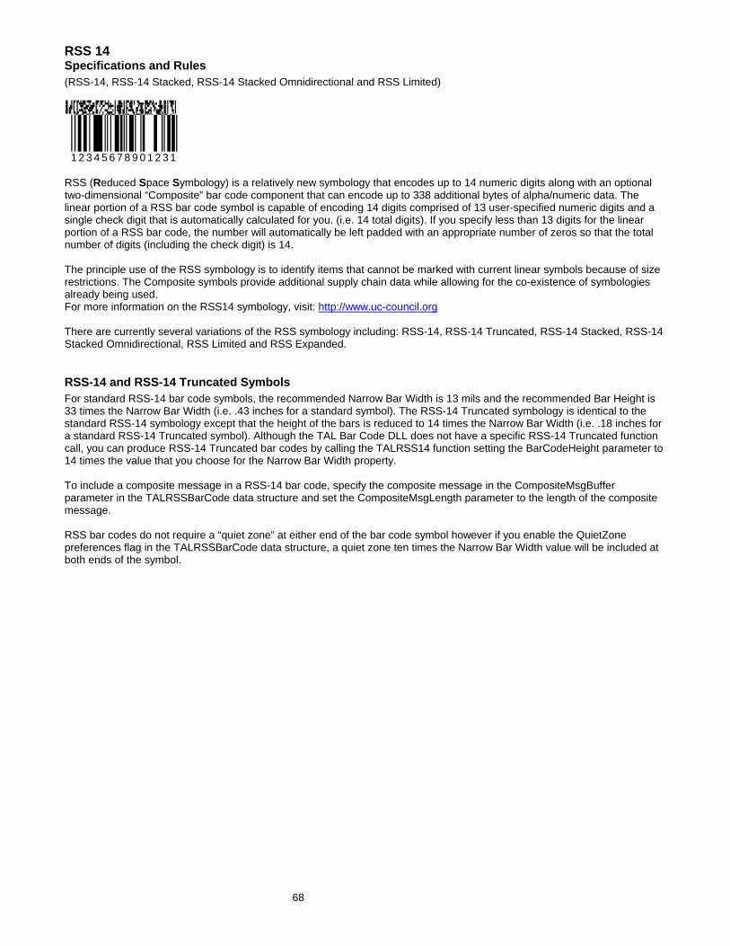
RSS 14 Specifications and Rules (RSS-14, RSS-14 Stacked, RSS-14 Stacked Omnidirectional and RSS Limited)
1 2 3 4 5 6 7 8 9 0 1 2 3 1
RSS (Reduced Space Symbology) is a relatively new symbology that encodes up to 14 numeric digits along with an optional two-dimensional “Composite” bar code component that can encode up to 338 additional bytes of alpha/numeric data. The linear portion of a RSS bar code symbol is capable of encoding 14 digits comprised of 13 user-specified numeric digits and a single check digit that is automatically calculated for you. (i.e. 14 total digits). If you specify less than 13 digits for the linear portion of a RSS bar code, the number will automatically be left padded with an appropriate number of zeros so that the total number of digits (including the check digit) is 14. The principle use of the RSS symbology is to identify items that cannot be marked with current linear symbols because of size restrictions. The Composite symbols provide additional supply chain data while allowing for the co-existence of symbologies already being used. For more information on the RSS14 symbology, visit: http://www.uc-council.org There are currently several variations of the RSS symbology including: RSS-14, RSS-14 Truncated, RSS-14 Stacked, RSS-14 Stacked Omnidirectional, RSS Limited and RSS Expanded. RSS-14 and RSS-14 Truncated Symbols For standard RSS-14 bar code symbols, the recommended Narrow Bar Width is 13 mils and the recommended Bar Height is 33 times the Narrow Bar Width (i.e. .43 inches for a standard symbol). The RSS-14 Truncated symbology is identical to the standard RSS-14 symbology except that the height of the bars is reduced to 14 times the Narrow Bar Width (i.e. .18 inches for a standard RSS-14 Truncated symbol). Although the TAL Bar Code DLL does not have a specific RSS-14 Truncated function call, you can produce RSS-14 Truncated bar codes by calling the TALRSS14 function setting the BarCodeHeight parameter to 14 times the value that you choose for the Narrow Bar Width property. To include a composite message in a RSS-14 bar code, specify the composite message in the CompositeMsgBuffer parameter in the TALRSSBarCode data structure and set the CompositeMsgLength parameter to the length of the composite message. RSS bar codes do not require a “quiet zone” at either end of the bar code symbol however if you enable the QuietZone preferences flag in the TALRSSBarCode data structure, a quiet zone ten times the Narrow Bar Width value will be included at both ends of the symbol.
68

69
RSS-14 Stacked RSS-14 Stacked is a variation of the standard RSS-14 symbology that allows the bar code to be printed in two rows. The purpose of RSS-14 Stacked is to reduce the overall length of the RSS-14 linear bar code so it can fit better on certain packaging configurations. This form of RSS-14 can be printed very small and is not generally intended for omnidirectional scanning. It is used to encode 14 digits of numerical data and just like the Standard RSS-14 symbology; it can also contain a composite component. The top row of the linear portion of a RSS-14 Stacked bar code symbol is always 5 times the narrow bar width in height and the bottom row is always 7 times the narrow bar width in height and the two rows are separated by a special separator pattern that is 1 times the Narrow Bar Width in height. With RSS-14 Stacked bar codes, you cannot set the bar height independently of the Narrow Bar Width value. RSS-14 Stacked Omnidirectional The RSS-14 Stacked Omnidirectional symbology is almost identical to RSS-14 Stacked except that the two rows of the linear portion of a RSS-14 Stacked Omnidirectional bar code symbol are always 33 times the narrow bar width in height and the two rows are separated by a special separator pattern that is 3 times the narrow bar width in height. Unlike RSS-14 Stacked, the RSS-14 Stacked Omnidirectional symbology is designed to facilitate omnidirectional scanning. With RSS-14 Stacked Omnidirectional bar codes, you cannot set the bar height independently of the Narrow Bar Width value. RSS Limited RSS Expanded is yet another smaller variation of the RSS-14 symbology. It is printed in a single row however it is slightly narrower than a standard RSS-14 symbol. The number that you encode in a RSS Limited bar code must be less than or equal to 1999999999999. In other words the first digit in a full 13-digit number cannot be greater than one. RSS Expanded RSS Expanded is a variable length linear symbology capable of encoding up to 74 numeric digits or 41 alphanumeric characters in either a single or multiple rows. RSS Expanded is currently not supported by the TAL RSS Bar Code DLL.

RSS14 Bar Code Dimensions The two main dimensions used to define the size of most common bar codes are the Narrow Bar Width and the overall Bar Height. The Height is generally less important than the Narrow Bar Width and you can scale the height to any size that you like unless you intend the bar code to be read by an omnidirectional scanner. The official specification for RSS14 bar codes recommends that you set the height of the bars to at least 33 times the Narrow Bar Width for omnidirectional scanning applications (this is the default value used by the TALRSS32.DLL functions if you pass in a value of zero for the BarHeight parameter). The Narrow Bar Width effectively determines the total width of a bar code symbol. All other bar and space width dimensions are based on this width (referred to as the nominal X dimension). The best choice for this dimension depends partly on the resolution of your bar code reading equipment and also on the resolution of the printer being used to produce the bar code. As a general rule the Narrow Bar Width should fall in a range between 10 to 30 mils (.25 to .76mm) and should never be less than 7.5 mils (13 mils (.33mm) is the most commonly recommended value for most bar code readers).
1 2 3 4 5 6 7 8 9 0 1
X=13 Sample
1 2 3 4 5 6 7 8 9 0 1
X=20 Sample
RSS14 bar codes may also contain a composite message. The composite message is an additional 2 dimensional bar code that is rendered directly above the main symbol. This composite bar code is made up of small modules where the width of each module is equal to the NarrowBarWidth parameter and the height of the individual modules is twice the NarrowBarWidth value. The composite message may contain up to 338 alpha/numeric data characters. Sample RSS14 bar code with a Composite Message
0 0 1 2 3 4 5 6 7 8 9 0 1
70

71
How to use the TAL RSS14 Bar Code DLL The TAL RSS14 Bar Code DLL contains four functions that you pass two type structures to. The first structure, a TALRSSBarCode structure, contains all the parameters necessary to create your bar codes including the message to encode, the height, the foreground and background colors and many other options that determine how the bar code should be produced. The second type structure is a standard Windows MetaFilePict type structure that is returned to your application to provide information about the bar code that was produced including the overall x and y dimensions of the bar code, the mapping mode or units of the x and y dimensions and also a handle to a memory based Windows Metafile if you set up the DLL call to output to a memory Metafile. All four functions return a 4 byte Long Integer that will be zero if the function is successful otherwise it will contain an error code indicating why it failed. The TALRSSBarCode structure provides input data to the DLL call and the MetaFilePict structure provides output data from the DLL call. Note: The DLL ignores any input data passed in the MetaFilePict structure therefore you do not have to worry about clearing the input values of this structure before you call the DLL. The TALRSSBarCode type structure contains a parameter named "OutputOption" that instructs the function how to output the bar code. Four options are available; You can output the bar code to the Windows Clipboard, save it to a disk file, store it to a memory Metafile or you can output directly to a device context handle (hDC). If you output your bar codes to a memory Metafile, you are responsible for rendering the bar code on a device context (i.e. screen or printer) and also for deleting the memory Metafile when you are done with it. If you output directly to a device context handle, the DLL will actually render the Metafile on the device for you and also delete the Metafile from memory before returning control to your application. Function names and DLL files for creating RSS14 bar codes. Function Name DLL File Symbologies Supported by the function TALRSS14 TALRSS32.dll RSS14 – with or without a composite component TALRSS14S TALRSS32.dll RSS14 Stacked – with or without a composite
component TALRSS14SO TALRSS32.dll RSS14 Stacked Omnidirectional – with or without a
composite component TALRSSLIM TALRSS32.dll RSS Limited – with or without a composite component TALRSS14.dll (Support DLL required by the TALRSS32.DLL file)

72
Visual Basic TALRSSBarCode Type Structure Declaration The following is a Visual Basic type declaration for the TALRSSBarCode data type with comments indicating the purpose of each individual data member. Refer to the TALRSSBarCode Type Structure Elements (pg. 74) for a more detailed description of each data member. Type TALRSSBarCode MessageLength As Long ' Length of message to be encoded MessageBuffer As String * 16 ' Message buffer CompositMsgLen As Long ‘ length of the composite component message CompositMsgBuffer as String * 340 ‘ composite message buffer CommentLength As Long ' Length of comment CommentBuffer As String * 100 ' Comment buffer NarrowBarWidth As Long ' Narrow Bar Width in units of .01 mm BarWidthReduction As Long ' Percent of NarrowBarWidth (see notes for details) BarCodeHeight As Long ' Height of Bars in units of .01 mm FGColor As Long ' Foreground RGB color BGColor As Long ' Background RGB color FontName As String * 32 ' Font name for human readable text and comment FontSize As Long ' Font size in points TextColor As Long ' Text color - RGB color value Orientation As Long ' Rotation 0 - 3 or 0, 90, 180, 270 degrees Preferences As Long ' Bit values as described below HorizontalDPI As Long ' Printer DPI values - used when AdjustToPrinterDPI VerticleDPI As Long ' flag is set in Preferences (see notes for details) OutputOption As Long ' 0=Clipboard, 1=SaveToFile, 2=MetaFilePict, 3=hDC
' (See notes for details) OutputFilename As String * 260 ' ASCIIZ filename when saving to disk (null terminated) OutputhDC As Long ' Output device context when outputting to hDC XPosInInches As Single ' X position when outputting to hDC (see notes for details) YPosInInches As Single ' Y position when outputting to hDC (see notes for details) Reserved As Long ' Reserved for future use End Type Visual Basic MetaFilePict Type Structure Declaration The MetaFilePict data structure is a standard Windows API data structure. The following is a sample Visual Basic declaration for the MetaFilePict data type. Type MetaFilePict ' 32 bit MetaFilePict Type Structure mm As Long ' Metafile map mode - this will always be MM_ANISOTROPIC (8) xExt As Long ' Width of the Metafile - TAL DLLs use units of .01 mm yExt As Long ' Height of the Metafile hMf As Long ' Handle to the actual Metafile in memory End Type

73
C/C++ TALRSSBarCode Type Structure Declaration The following is a C/C++ declaration for the TALRSSBarCode data type with comments indicating the purpose of each individual data member. Refer to the TALRSSBarCode Type Structure Elements (pg. 74) for a more detailed description of each data member. typedef struct tagTALRSSBarCode { long messageLength; // Length of message to be encoded char messageBuffer[16]; // Message buffer long cmpMsgLength; // Length of composite message char cmpmessageBuffer[340]; // Composite Message buffer long commentLength; // Length of comment char commentBuffer[100]; // Comment buffer long narrowBarWidth; // Narrow Bar Width in units of .01 mm long barWidthReduction; // Percent of NarrowBarWidth long barCodeHeight; // Height of Bars in units of .01 mm COLORREF fgColor; // Foreground Color COLORREF bgColor; // Background Color char fontName[32]; // Font name for human readable text long fontSize; // Font size in points COLORREF textColor; // Text color - RGB color value long orientation; // Rotation 0 - 3 or 0, 90 , 180, 270 degrees long preferences; // Bit values as described below long horizontalDPI; // Printer DPI values - used when AdjustToPrinterDPI long verticleDPI; // flag is set in Preferences (see notes below) long outputOption; // 0=Clipboard, 1=File, 2=MetaFilePict, 3=hDC char outputFilename[260]; // ASCIIZ filename when saving to disk HDC outputDC; // Output device context when outputting to hDC float XPosInInches; // X page position (when outputting to hDC) float YPosInInches; // Y page position (when outputting to hDC) long reserved; // Reserved for future use } TALRSSBarCode;
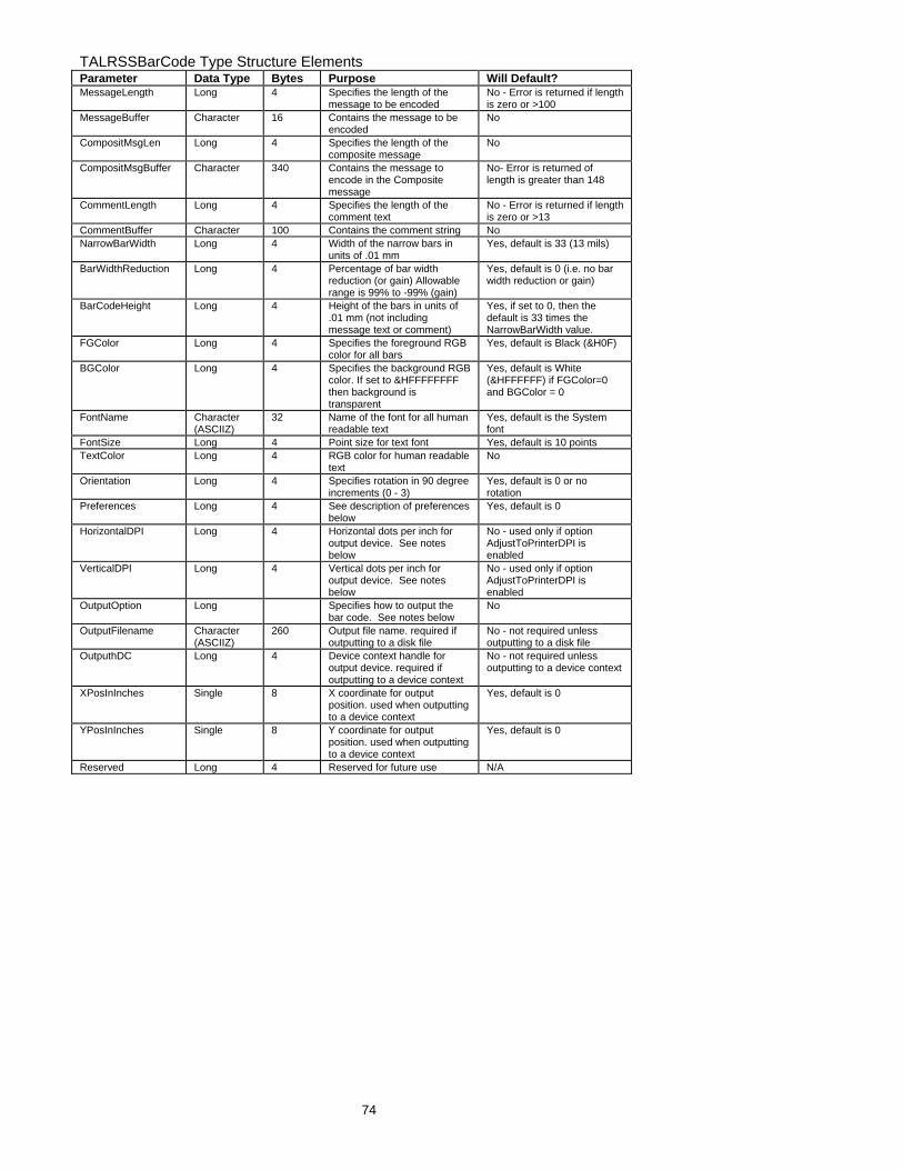
74
TALRSSBarCode Type Structure Elements Parameter Data Type Bytes Purpose Will Default? MessageLength Long 4 Specifies the length of the
message to be encoded No - Error is returned if length is zero or >100
MessageBuffer Character 16 Contains the message to be encoded
No
CompositMsgLen Long 4 Specifies the length of the composite message
No
CompositMsgBuffer Character 340 Contains the message to encode in the Composite message
No- Error is returned of length is greater than 148
CommentLength Long 4 Specifies the length of the comment text
No - Error is returned if length is zero or >13
CommentBuffer Character 100 Contains the comment string No NarrowBarWidth Long 4 Width of the narrow bars in
units of .01 mm Yes, default is 33 (13 mils)
BarWidthReduction Long 4 Percentage of bar width reduction (or gain) Allowable range is 99% to -99% (gain)
Yes, default is 0 (i.e. no bar width reduction or gain)
BarCodeHeight Long 4 Height of the bars in units of .01 mm (not including message text or comment)
Yes, if set to 0, then the default is 33 times the NarrowBarWidth value.
FGColor Long 4 Specifies the foreground RGB color for all bars
Yes, default is Black (&H0F)
BGColor Long 4 Specifies the background RGB color. If set to &HFFFFFFFF then background is transparent
Yes, default is White (&HFFFFFF) if FGColor=0 and BGColor = 0
FontName Character (ASCIIZ)
32 Name of the font for all human readable text
Yes, default is the System font
FontSize Long 4 Point size for text font Yes, default is 10 points TextColor Long 4 RGB color for human readable
text No
Orientation Long 4 Specifies rotation in 90 degree increments (0 - 3)
Yes, default is 0 or no rotation
Preferences Long 4 See description of preferences below
Yes, default is 0
HorizontalDPI Long 4 Horizontal dots per inch for output device. See notes below
No - used only if option AdjustToPrinterDPI is enabled
VerticalDPI Long 4 Vertical dots per inch for output device. See notes below
No - used only if option AdjustToPrinterDPI is enabled
OutputOption Long Specifies how to output the bar code. See notes below
No
OutputFilename Character (ASCIIZ)
260 Output file name. required if outputting to a disk file
No - not required unless outputting to a disk file
OutputhDC Long 4 Device context handle for output device. required if outputting to a device context
No - not required unless outputting to a device context
XPosInInches Single 8 X coordinate for output position. used when outputting to a device context
Yes, default is 0
YPosInInches Single 8 Y coordinate for output position. used when outputting to a device context
Yes, default is 0
Reserved Long 4 Reserved for future use N/A

75
TALRSSBarCode Data Type Member Descriptions and Notes MessageLength The MessageLength parameter specifies the length of data to be encoded. The allowable range is 1 to 13 for RSS bar codes. The actual message will be passed in the MessageBuffer parameter. MessageBuffer Contains linear portion of the message that you want encoded. The message must consist of from 1 to 13 numeric digits. RSS bar codes actually encode a 14 digit number where the first 13 digits are a value that is supplied by the user and the 14th digit is a check digit that is automatically calculated for you by the TALRSS32.DLL. If you supply less than 13 digits for the message, then the DLL will automatically left pad the number that you supply with leading zeros to produce a 13 digit number. For additional information, refer to the Symbology Descriptions and Rules for the RSS14 (pg. 68). CompositMsgLen The CompositMsgLen parameter specifies the length an optional composite message to be encoded along with the standard RSS14 message. The allowable range for this parameter is 0 to 338 for RSS14 bar codes. The actual composite message will be passed in the CompositMsgBuffer parameter. CompositMsgBuffer Contains the composite message that you want encoded. The composite message is an optional message that may contain of from 0 to 338 alpha/numeric characters. For additional information, refer to the Symbology Descriptions and Rules for the RSS14 (pg. 68). CommentLength Specifies the length of an optional comment that you want to appear either above or below the bar code. The allowable range is 0 to 100. (Zero means that you do not want a comment in the bar code. The position of the comment is specified using a flag in the "Preferences" variable. (See the notes for the Preferences variable on pg. 24 for additional information.) CommentBuffer Contains the comment message. Comments can contain any ASCII character. NarrowBarWidth The NarrowBarWidth (expressed in integer units of .01 mm) specifies the width of the narrowest bar in the bar code. All other bar and space width dimensions are based on this width (referred to as the nominal X dimension). This parameter effectively determines the total width of a bar code symbol. The best choice for this dimension depends partly on the resolution of your bar code reading equipment and also on the resolution of the printer being used to produce the bar code. As a general rule the Narrow Bar Width should fall in a range between 10 to 30 mils (25 to 76 in units of .01 mm) and should never be less than 7.5 mils. 13 mils (.33 mm) is the most commonly recommended value for most bar code readers). The allowable range of values for NarrowBarWidth in the TAL Bar Code DLLs is 0 to 300. If you pass the value zero, the default value of 33 (13 mils) will be used.

76
BarWidthReduction The BarWidthReduction parameter allows you to set a Reduction or Gain factor ranging from 99 (% reduction) to -99 (% gain). Specifying a non-zero value for the BarWidthReduction parameter causes the DLL to reduce or enlarge the width of all solid bars in a bar code. Bar Width Reduction is often necessary to compensate for ink spread when generating bar codes that will be used in wet ink printing processes. The percentage that you specify is based on the narrow bar width that you choose for your bar codes. For example if you specify a BarWidthReduction value of 25 and your narrow bar width is set at 10 mils, the width of all bars in your bar codes will be reduced by 2.5 mils (25% of 10 mils = 2.5 mils). Bar width gain is typically used when printing on glass or other surfaces that cause ink to bead up or shrink as it dries. To specify bar width gain instead of reduction, use a negative percentage value. An error is returned if you specify a BarWidthReduction value greater than 99 or less than -99. BarCodeHeight Specifies the height of the bars in the primary portion of the RSS14 bar code in units of .01 mm. The allowable range for this parameter is 100 to 20000 or zero. If you specify zero as the BarCodeHeight, the default value of 33 times the NarrowBarWidth parameter will be used. This parameter only applies to standard RSS-14 and RSS Limited bar codes. RSS-14 Stacked and RSS-14 Stacked Omnidirectional bar codes use a multiple of the NarrowBarWidth value for the height of the bars therefore the height cannot be set independently of the NarrowBarWidth parameter. For more information, see the symbology descriptions for RSS Stacked and RSS Stacked Omnidirectional bar codes (pg. 68) FGColor & BGColor Specifies the Foreground and Background RGB colors for your bar codes. If both the FGColor and the BGColor parameters are set to zero then the default values of black bars on a white background will be used. The allowable range of color values is 0 representing black to 16777215 (hex &HFFFFFF) representing white. If you specify &HFFFFFFFF as the background color, then the background will be transparent. Note: It is entirely possible to choose color combinations that render a bar code symbol unreadable. Although two colors may appear to the human eye to have a high of contrast between them, a bar code reader may not be able to determine any difference at all between the two colors. Solid black bars on a solid white background always produces the best results. If you must use colors other than black on white, a good rule of thumb is to select solid foreground colors with a luminescence value no greater than 60 and select solid background colors with a luminescence value no less than 180. See Also: How To Produce Readable Bar Codes (pg. 31)

77
FontName The FontName parameter allows you to choose the font for the human readable text in your bar codes. If you do not specify a font name, the DLL will use the default "System" font. Different fonts behave differently thus some fonts may appear different on screen than when printed. True Type fonts are the most WYSIWYG and they also align better when rotated. Note: Most bar code symbology specifications recommend the font OCR-B (Optical Character Recognition revision B). The choice of font is not critical however it is a good idea to choose fonts that are close to the recommended specification. The System font and the font MS Sans Serif are both very close to OCR-B as is the True Type Font Arial. FontSize Specifies the font size in points for all human readable text. The allowable range is zero to 1000 points. If you specify zero then the default font size of 10 points will be used. Note: When the Automatic Font Scaling option is used in the Preferences variable, it will override any font size entered for the FontSize parameter. See the Preferences parameter for details. TextColor Specifies the foreground RGB color for all human readable text. The allowable range of color values is 0-representing black to 16777215 (hex &HFFFFFF) representing white. Orientation The Orientation parameter allows you to rotate a bar code symbol in increments of 90 degrees from horizontal. Four choices of orientation are available, 0, 1, 2 and 3. Specifying 0 tells the DLL to produce normal Horizontal bar codes. Specifying 1 causes the bar code to be rotated 90 degrees clockwise (Vertical), specifying 2 rotates the bar code 180 degrees (upside down) and specifying 3 rotates the bar code 270 degrees clockwise (vertical). If you specify a value that is outside the allowable range of 0 to 3, the DLL will perform a logical AND on the number that you supply with the value 3 and then use the resulting value. Preferences The Preferences option allows you to choose specific options available in each bar code symbology by setting bit values in the Preferences variable. You enable a particular preference option by ORing the Preferences variable with a particular constant value. See the Preferences section of this manual (pg. 24) for a complete description of all available Preferences options and their respective constant values.

78
HorizontalDPI and VerticleDPI The HorizontalDPI and VerticleDPI parameters only have meaning when the Pref_AdjustToPrinterDPI option is set in the Preferences variable. See the notes for the preferences constant Pref_AdjustToPrinterDPI for details (pg. 26). OutputOption The OutputOption variable allows you to select the method that the DLL will use to output your bar codes. The TAL RSS14 Bar Code DLL support four possible output options that are selected by using the following values:
Option Value Output Action OutputToClipboard 0 Places the bar code in the Windows clipboard. OutputToDiskFile 1 Stores the bar code in a disk file as a WMF file. OutputToMemoryMetaFile 2 Stores the bar code in a memory MetaFile. OutputTohDC 3 Paints the bar code to a device context.
The OutputToClipboard and OutputToDiskFile options are typically used when the programming language that you are using does not provide access to device context handles for screen windows. Visual Basic for Applications (as in MS Word and Access) is one such language (not to be confused with Microsoft Visual Basic). Because you do not have access to device context handles, you cannot use the PlayMetaFile Windows API function to render your bar codes on screen. You can however retrieve graphics from the clipboard or from a disk file in VBA and most other similar languages. Note: When outputting to a disk file, you have the option of storing the Metafile as a standard Windows Metafile or as an Aldus Placeable Metafile. The default is to store a standard Windows Metafile. To create an Aldus Placeable Metafile, you use the Pref_MakeAldusMetaFile constant with the Preferences parameter. Note: All newer versions of Word, Access and most other Microsoft applications require Aldus Placeable Metafiles and will not recognize standard Metafiles. The OutputTohDC option can be used to have the DLL perform almost all of the work of creating and also rendering the bar code directly on a device context (hDC). This option is the most powerful because the DLL does everything for you including create the bar code, render it on a device and also delete the Metafile from memory. For simpler applications that require small numbers of bar codes, this option is probably the best because it requires the least additional code and it cleans up after itself leaving you little to worry about. The OutputToMemoryMetaFile option is the most flexible of the four options because it creates the bar code to a memory based Metafile and then leaves it in memory so that you can access it as needed. C/C++ programmers will probably find this method to be the best one to use. The Metafile is accessed using a Metafile handle (hMF) that is passed back to your application in a MetaFilePict type structure. The MetaFilePict structure contains several parameters including size information and the handle to the Metafile (hMF) containing your bar code. The hMF parameter in the MetaFilePict structure (returned by the DLL call) will be zero for all output options except when outputting to a memory Metafile.

79
Important: When you output to a memory Metafile, your application is responsible for deleting the Metafile when it is no longer needed by calling the Windows API function DeleteMetaFile. If you do not delete the Metafile, it will stay in memory after your application exits resulting in a "memory leak". The OutputToMemoryMetaFile option is the most flexible way to use the bar code DLLs because you only need to create each bar code once. After a bar code has been created, you can output it to the screen, the printer or both as necessary without having to create it again. When the DLL is called to output to either the clipboard, a disk file or directly to a hDC, the DLL will delete the Metafile from memory thus saving you the trouble. In these cases the DLL will set the hMF member of the MetaFilePict returned by the DLL to zero to make sure that you cannot try to access it. OutputFileName The OutputFileName parameter is the name and path for a disk file where you would like your bar code saved. This parameter is required when you use the "OutputToDiskFile" Output Option. For all other output options this parameter is ignored. The file name must be passed as a null terminated string (ASCIIZ). If you pass an illegal file name, the DLL function call will fail and return an "Invalid Filename" error. OutputhDC The OutputhDC parameter is the device context handle (hDC) for the output device where you would like your bar code displayed or printed. This parameter is required when you use the "OutputTohDC" Output Option. For all other output options this parameter is ignored. XPosInInches and YPosInInches The XPosInInches and YPosInInches variables are used to specify the position on a device context (printer page or screen window) where you would like your bar code drawn when you use the output option "OutputTohDC”. Since the DLL will be drawing the bar code directly to the device, these parameters let you specify the coordinates on the page or window (in inches) for the upper left corner of your bar code. These parameters are only valid when the output option is set to "OutputTohDC" and are ignored for all other output options. These parameters are expected as positive values with the upper left corner of the page being position 0,0. The values passed to the DLL must fall within the height and width of the screen window or the printer page sizes for the output device. Since these values are passed as single precision variables and not integers, you can specify fractional coordinate values.

80
Powerbuilder TALBarCode Sample Declaration type TALBarCode from structure long l_messagelength character c_messagebuffer[100] long l_commentlength character c_commentbuffer[100] long l_narrowbarwidth long l_barwidthreduction long l_barcodeheight long l_fgcolor long l_bgcolor long l_narrowtowideratio character c_fontname[32] long l_fontsize long l_textcolor long l_orientation long l_preferences long l_horizontaldpi long l_verticaldpi long l_outputoption character c_outputfilename[260] long l_outputhdc long l_rxposininches long l_ryposininches long l_reserved end type type MetafilePict from structure long l_mapmode long l_xdimension long l_ydimension long l_handle end type // Sample TALCode39 function declaration FUNCTION long TALCode39 (TALBarCode lstr_bc, REF MetafilePict lstr_mfp) LIBRARY "TALC3932.DLL" TALBarCode lstr_bc // create a TALBarCode variable MetafilePict lstr_mfp // create a MetafilePict variable lstr_bc.l_messagelength = 10 // set values for TALBarCode "lstr_bc" member variables lstr_bc.c_messagebuffer = '1234567890' // fill in all required variables before the DLL call // Note: In Powerbuilder, the easiest way to call the DLLs is to use the "OutputToClipboard" // option and paste the bar code into a rich text edit box as in the following code: rte_barcode.clear() // clear out a rich text edit window lreturn = TALCode39(lstr_bc, lstr_mfp) // call the DLL if lreturn = 0 then // if return value is not zero rte_barcode.paste() // paste the bar code into the edit box else // otherwise messagebox("Bar Code Error", string(lreturn)) // display error end if

81
Error Codes Returned by the TAL Bar Code DLLs 1 = Invalid Message - Message is either empty or contains invalid characters 2 = Invalid message length - Message is too long 3 = Invalid comment length - Comment length is too long 4 = Invalid supplemental - UPC or EAN supplemental contains non numeric data 5 = Invalid supplemental length - UPC or EAN supplemental has other than 2 or 5 digits 6 = Invalid narrow bar width - Narrow bar width is either <= 0 or greater than 500 7 = Invalid bar width reduction/gain - Bar width reduction is not between -99% to 99% 8 = Invalid height - Height for standard bar codes must range from .1 to 200 9 = Invalid foreground or background color Colors must be either hex FFFFFFFF (transparent) or may range from 0 to hex FFFFFF 10 = Invalid orientation value - Orientation parameter is outside the allowable range of 0 - 3 12 = Invalid narrow to wide ratio - Must be a integer from 20 to 30 representing 2.0 to 3.0 13 = Invalid font size - Font size is either zero or greater than 1000 14 = Bar code too large - Overall dimensions of the bar code were too large 15 = Invalid printer resolution - Specified printer resolution was less than 72 DPI 16 = Filename not specified - Save to disk option was chosen with no file name specified. 17 = Unable to create Metafile file Either a bad filename was specified or the DLL was unable to open file, etc... 18 = Invalid Device Context The output to hDC option was chosen but the device context (hDC) was not valid 19 = Invalid Output Option - OutputOption parameter must be between 0 and 3 Visual Basic Error Constant Declarations: Global Const TALErr_InvalidMessage = 1 Global Const TALErr_InvalidMsgLen = 2 Global Const TALErr_InvalidCommentLen = 3 Global Const TALErr_InvalidSupplement = 4 Global Const TALErr_InvalidSupplementLen = 5 Global Const TALErr_InvalidBarWidth = 6 Global Const TALErr_InvalidBarWidthReduction = 7 Global Const TALErr_InvalidHeight = 8 Global Const TALErr_InvalidColor = 9 Global Const TALErr_InvalidOrientation = 10 Global Const TALErr_InvalidNarrowToWideRatio = 12 Global Const TALErr_InvalidFontSize = 13 Global Const TALErr_BarCodeTooLarge = 14 Global Const TALErr_InvalidPrinterResolution = 15 Global Const TALErr_MissingFileName = 16 Global Const TALErr_UnableToCreateMetafile = 17 Global Const TALErr_InvalidDeviceContext = 18 Global Const TALErr_ InvalidOutputOption = 19