WIND ENERGY Wind Energ. 2003; 6:129–159 (DOI:...
31
WIND ENERGY Wind Energ. 2003; 6:129–159 (DOI: 10.1002/we.77) Historical Review The History and State of the Art of Variable-Speed wind Turbine Technology P. W. Carlin, * A. S. Laxson and E. B. Muljadi, National Renewable Energy Laboratory/National Wind Technology Center, 1617 Cole Boulevard, Golden, CO 80401, USA Key words: variable-speed wind turbines; wind turbine controls; windmill technology; windmill history; wind energy bibliography Early wind turbines used for performing mechanical work (pumping, grinding and cutting) optimized aerodynamics by being allowed to run at variable speed. Some of the earliest DC electric wind turbines were allowed to run at variable speed. With the advent of grid- connected AC turbines, rotational speeds were limited in order to control the wind turbine AC frequency output to equal the grid frequency. With the advent of semiconductor devices, attempts began as early as the 1970s to allow variable-speed operation of large-scale turbines. The introduction of a new generation of high-voltage, high-speed power electronic components allows a wide range of variable-speed operation for very-large-scale machines. Over the past 30 years a number of designs have been tested, a few of which have entered commercial operation. A number of these designs and their histories are described. A detailed description of a wide range of electrical methods for allowing variable-speed operation is provided. Copyright 2003 John Wiley & Sons, Ltd. Introduction The earliest horizontal-axis windmill to use the principles of aerodynamic lift instead of drag may have been introduced in the 12th century. These horizontal-axis sail turbines were allowed to run at varying speeds, limited only by braking or furling to control their speed during storms. This behaviour occurred naturally, and for most uses a particular speed was unimportant. These designs operated throughout Europe and in the Americas into the present century. In the 700 or so years since the first sail wing turbine, craftsmen discovered many of the practical structural and operational rules without understanding the physics behind them. It was not until the 19th century that these principles began to be clearly understood. In the early 19th century the classic American water pumper was introduced. The need for this machine was driven by the phenomenal growth of agriculture in the American Midwest, beginning with the opening of the northwestern prairie states in the early 1800s. More than a million of these machines dotted the Midwest and West starting in the early 1850s. Even now these multibladed farm windmills can be seen throughout the western United States and Canada, where the energy and storage requirements for providing drinking water for cattle are well matched to the wind water pumper’s power, the storage capacity of the associated stock tank, and the wind statistics of the Great Plains. These machines use the most rudimentary aerofoils (often flat plates or slats of wood) and are allowed to rotate proportionally to wind velocity. For the purposes of direct mechanical water pumping, this variable-speed operation works effectively. Even though the American water-pumping design gives up something by its dependence on a flat-plate aerofoil, its simplicity, ease of construction, and reliability still make it ideal for its intended purpose. L Correspondence to: P. W. Carlin, National Renewable Energy Laboratory/National Wind Technology Center, 1617 Cole Boulevard, Golden, CO 80401, USA. E-mail: Palmer [email protected] Published online 7 February 2003 Received 28 February 2002 Copyright 2003 John Wiley & Sons, Ltd.
Transcript of WIND ENERGY Wind Energ. 2003; 6:129–159 (DOI:...
WIND ENERGYWind Energ. 2003; 6:129–159 (DOI: 10.1002/we.77)
HistoricalReview
The History and State of the Art ofVariable-Speed wind TurbineTechnologyP. W. Carlin,! A. S. Laxson and E. B. Muljadi, National Renewable Energy Laboratory/NationalWind Technology Center, 1617 Cole Boulevard, Golden, CO 80401, USA
Key words:variable-speedwind turbines;wind turbinecontrols;windmilltechnology;windmillhistory; windenergybibliography
Early wind turbines used for performing mechanical work (pumping, grinding and cutting)optimized aerodynamics by being allowed to run at variable speed. Some of the earliestDC electric wind turbines were allowed to run at variable speed. With the advent of grid-connected AC turbines, rotational speeds were limited in order to control the wind turbineAC frequency output to equal the grid frequency. With the advent of semiconductor devices,attempts began as early as the 1970s to allow variable-speed operation of large-scaleturbines. The introduction of a new generation of high-voltage, high-speed power electroniccomponents allows a wide range of variable-speed operation for very-large-scale machines.Over the past 30 years a number of designs have been tested, a few of which have enteredcommercial operation. A number of these designs and their histories are described. A detaileddescription of a wide range of electrical methods for allowing variable-speed operationis provided. Copyright ! 2003 John Wiley & Sons, Ltd.
Introduction
The earliest horizontal-axis windmill to use the principles of aerodynamic lift instead of drag may have beenintroduced in the 12th century. These horizontal-axis sail turbines were allowed to run at varying speeds,limited only by braking or furling to control their speed during storms. This behaviour occurred naturally,and for most uses a particular speed was unimportant. These designs operated throughout Europe and in theAmericas into the present century. In the 700 or so years since the first sail wing turbine, craftsmen discoveredmany of the practical structural and operational rules without understanding the physics behind them. It wasnot until the 19th century that these principles began to be clearly understood.
In the early 19th century the classic American water pumper was introduced. The need for this machinewas driven by the phenomenal growth of agriculture in the American Midwest, beginning with the opening ofthe northwestern prairie states in the early 1800s. More than a million of these machines dotted the Midwestand West starting in the early 1850s. Even now these multibladed farm windmills can be seen throughout thewestern United States and Canada, where the energy and storage requirements for providing drinking waterfor cattle are well matched to the wind water pumper’s power, the storage capacity of the associated stocktank, and the wind statistics of the Great Plains. These machines use the most rudimentary aerofoils (oftenflat plates or slats of wood) and are allowed to rotate proportionally to wind velocity. For the purposes ofdirect mechanical water pumping, this variable-speed operation works effectively. Even though the Americanwater-pumping design gives up something by its dependence on a flat-plate aerofoil, its simplicity, ease ofconstruction, and reliability still make it ideal for its intended purpose.
! Correspondence to: P. W. Carlin, National Renewable Energy Laboratory/National Wind Technology Center, 1617 ColeBoulevard, Golden, CO 80401, USA. E-mail: Palmer [email protected]
Published online 7 February 2003 Received 28 February 2002Copyright " 2003 John Wiley & Sons, Ltd.
130 P. W. Carlin, A. S. Laxson and E. B. Muljadi
The early 20th century saw the start of the electric era. The rapid advances in motor, generator, lightingand appliance designs by Edison, Steinmetz, Tesla and others offered the promise of an electric-poweredutopia. The homes and farms of America were not immune to this desire, and, for remote locations, windturbines offered great promise. As early as 1888 the Brush wind turbine in Cleveland, Ohio had produced12 kW of direct current (DC) power for battery charging at variable speed. DC and variable-speed windturbines seemed only natural. Most early electric motors required direct current, and the varying voltage dueto turbulent winds was held relatively constant by the associated battery bank. At remote farms, where powerlines might never reach, a DC wind turbine could charge batteries and operate equipment.
In 1925, Marcelleus and Joseph Jacobs began work on the first truly high-speed, small-size, affordablebattery-charging turbine. Thousands of their 32 and 110 V DC machines were manufactured starting in thelate 1920s and running into the 1950s. This machine was followed by others such as the Windcharger. Thesecould be set up easily and required little if any maintenance. All these machines were allowed to run atvariable speed. Even after AC utility power had begun to spread through cities and towns, Sears Roebuckand others manufactured and distributed a wide range of products designed to run on DC to satisfy the needsof remote farms and ranches using batteries and variable-speed DC turbines.
In 1937 the creation of the Rural Electric Associations started the demise of these stand-alone variable-speed DC machines. As AC power lines spread throughout rural America, the need for such machines beganto fade. America was becoming connected, and in the future would depend upon large central power plantsto produce electricity for all. Long transmission lines required much higher voltage for efficient distribution.Electric transformers and their required alternating current were the obvious technology to employ. It wasthen necessary to standardize on constant voltage levels and a constant frequency. In North America, thisfixed frequency became 60 Hz. The simple variable-speed wind turbines had no economical way of eitherinterconnecting to these grids or supplying power for the many new appliances that began to fill farmhouseholds. The return to power independence for the American farmer and rancher would have to wait fora new generation of technologies.
Despite the apparent difficulties of connecting a wind turbine to the AC electrical grid, as early as 1939in the United States, such a step had been explored. Even earlier examples of large turbines used to produceelectricity tied to an established AC electrical grid may be cited; however, for depth of engineering and breadthof vision, few early pioneers have surpassed Palmer Putnam’s Grandpa’s knob machine. This machine wasincredibly advanced for its day, with full-span pitch control, active yaw drive, two-bladed flapping rotor and1"25 MW rating. The Smith–Putnam turbine rotor avoided the problem of variable speed by running at a fixedrpm locked to a synchronous generator directly tied to the electrical grid. However, by fixing the rotationalrate of the turbine to that of the electric grid, the turbine suffered severe fatigue damage from the load spikesduring wind gusts. Of course, it also lost energy collection efficiency as well.
The dream of a variable-speed wind turbine tied to the AC electrical grid began to become a viable realityin the early to the mid-1970s. Machines went on-line in the United States and Europe, using several differentmethods for transforming variable-voltage, variable-frequency outputs to reliable constant-voltage, constant-frequency outputs. In addition to large grid-connected machines, small stand-alone machines were developedthat incorporated these new technologies and would allow the farmer or homeowner to produce his ownpower, and to someday allow him to sell his excess power back to the utility grid. For example, the 8 kWWindworks machine of the early 1970s used a diode bridge to rectify the variable-frequency output of thepermanent magnet generator. Silicon-controlled rectifiers (SCRs) were used to invert the resulting DC intoutility AC synchronized to the grid. Technologies like these are still in use and are being further developed.Other new technologies are under constant development.
Significant issues must be addressed, however, in order for variable-speed technology to become a dominantfeature of future turbine designs. Designs must be optimized to lower cost of energy, which is a primary factorin the acceptance of wind technology into a utility’s generation mix. This cost of energy will be greatly affectedby the cost of potentially expensive power electronics, control systems or unique generator designs. Althoughvariable-speed operation can reduce the impact of transient wind gusts and subsequent component fatigue,this is still an unknown factor that must now be quantified. Generating clean power to meet standards such as
Copyright " 2003 John Wiley & Sons, Ltd. Wind Energ. 2003; 6:129–159

Variable-Speed Wind Turbine Technology 131
Institute of Electrical and Electronics Engineers (IEEE) 519 and International Electrotechnical Commission(IEC) 1000-3-2 will be a continuing challenge. For many technology developers, however, variable-speedoperations must become a key component of the wind generator of the future given the prospects of increasedperformance and decreasing costs.
Before turning to recent cases of variable-speed wind turbine operation, the following section will remindus of the intrinsic incompatibility between wind turbine mechanical energy conversion and existing electricutility technology. For a wind turbine we know that the best mechanical energy extraction occurs for a narrowrange of angles of attack of the air over the wind turbine blade aerofoils. This implies that, to maintain anoptimum attack angle as the wind speed varies, the turbine rotational speed must vary proportionally tothe wind speed. On the other hand, a century of electric power technology development has responded tocivilization’s demand for dependable constant voltages and frequencies by creating generators that operate atextremely constant speeds.
Obviously, a marriage of wind energy to existing utility grid energy requires some compromise. It is notsurprising that, because of the size and age of electrical technology, the compromise has been decidedlyone-sided. That is, at present, nearly all utility-connected wind machines are constrained by their generatorsto operate at exactly constant speed for synchronous generators or within a few per cent of constant speed forinduction generators. Wind turbine designers have long been aware of the preceding mismatch of wind withgrid and have sought techniques to alleviate it. One can see this is a standard engineering trade-off problemwhere the designer balances the advantages of a more complicated design against its disadvantages and costs.
Fixed Speed Versus Variable-Speed
Before presenting particular cases of variable-speed machine operation, let us review the commonly usedsimple theory of wind turbine behaviour.
Because wind turbine mechanical power at the rotor hub depends on both rotor speed and wind speed,harvested power can be represented on a three-dimensional surface. Figure 1 is an example of the characteristicpower surface of a small turbine. Blade pitch is assumed constant. We assume that the increasing power athigher wind and rotor speeds has been truncated to 20 kW by a control system. As expected, power out riseswith increasing wind and increasing rotor speed for low and moderate values.
Although the isometric view of Figure 1 helps us to visualize the surface, a vertical projection or contourmap of this surface can better illustrate certain features. A view vertically down on the surface is shown inFigure 2 for the lower wind speeds. Two important lines representing possible loci of wind turbine operationhave been drawn on the surface. These lines are actually edge views of vertical planes intersecting the powersurface of Figure 1. Recall that for all points on any line (or plane) through the origin the ratio of rotor speedto wind speed is constant. Using the turbine radius, we can map the rotor speed into the linear speed of thetips of the rotor blades. The ratio of this linear speed to the instantaneous wind speed is a dimensionlessmeasure of the slope of this line and is called the ‘tip speed ratio’ or !.
For the case shown, this linear speed is seven times faster than the wind speed for that point and is the mostimportant radial line that can be drawn on this surface. On this chart the line passes into each next higherpower contour at a rotor speed corresponding to the least wind that will support that level of power output,i.e. at the point on the contour that bulges farthest to the left. Thus it is obvious that, to collect maximuminstantaneous power at an existing wind speed, one should attempt to force the wind turbine to follow thisoperating locus. By imagining tip speed ratio lines drawn with other slopes on either side of ‘7’, one cansee that, even if a turbine operates at variable speed along those lines, a given wind will produce less powerfrom this machine than for the optimal ratio of 7.
The other line, ! D 13, divides the positive or power-producing region from the negative or power-consuming (fan) region. Thus this line defines the ‘runaway speed’ of a wind turbine, because it givesthe unloaded rotor speed for each wind speed. The rotor tips will be travelling 13 times faster than thewind speed.
Copyright " 2003 John Wiley & Sons, Ltd. Wind Energ. 2003; 6:129–159

132 P. W. Carlin, A. S. Laxson and E. B. Muljadi
5 10
15
20
25
020
40
60
8010012
0
-4-202468
101214161820
Pow
er -
kw
Wind - m/sRotor RPM
Figure 1. Generic turbine power surface truncated to 20 kW
Finally, this projection shows one way to compare performance of variable- and constant-speed operation.Suppose that this wind turbine is operating at a constant speed of 40 rpm and the wind speed is 3 m s#3. Thecontours indicate that the machine will be producing less than 1 kW of power. If the wind suddenly increasesto 6 m s#1 but the machine is constrained to remain at 40 rpm, the operating point will have only moved upone level of power. If, on the other hand, the machine had been allowed to increase speed and follow the! D 7 locus, the operating point would have moved upward three power contour levels for the same 6 m s#1
wind. Dynamic effects of changing wind speeds in real machines will probably cause operating loci to formelliptical contours whose axes approximate the straight line.
With a wind turbine that can produce power over a continuous range of rotor speeds, a machine can bemade to operate constantly at or near its optimum tip speed ratio. By doing this, the turbine, depending onturbine aerodynamics and wind regime, will on average collect up to 10% more annual energy, as illustratedpreviously. This can yield a significant revenue increase over a 20 or 30 year life of operation. However,there are a number of issues associated with variable-speed operation that must be dealt with before such adesign attains its most desired form.
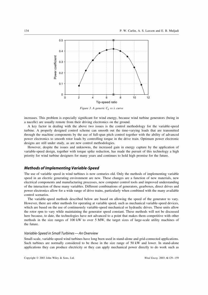
The traditional way to present the preceding information is with the ‘power coefficient versus tip speedratio’ (Cp vs !) curve, as seen in Figure 3. Recall that the power coefficient is numerically the fraction ofthe total wind kinetic energy that is captured from the swept area. Tip speed ratios for best power coefficientfor most wind turbines usually lie between 5 and 10.
For fixed-rpm machines, there is only one wind velocity on the turbine’s power curve (power versus windspeed) at which the tip speed ratio is optimum, because there is only one wind speed exactly one-seventh (inthis example) of the blade tip speed. Clearly, unless the wind regime at a particular site is highly peaked atexactly that wind velocity, the wind turbine will often be operating off of its optimum performance and notextracting the maximum power from the wind.
Note in Figure 3 that the power coefficient is poorly defined at the lower tip speed ratios, because, if theblade pitch has not changed, the blades will be stalled. At high tip speed ratios the axis crossing is welldefined and indicates the zero-torque or ‘runaway’ rotor speed.
Copyright " 2003 John Wiley & Sons, Ltd. Wind Energ. 2003; 6:129–159

Variable-Speed Wind Turbine Technology 133
14-15
13-14
12-13
11-12
10-11
9-10
8-9
7-8
6-7
5-6
4-5
3-4
2-3
1-2
0-1
-1-0
-2--1
-3--2
-4--3
0
10
0 1 2 3 4 5 6 7 8 9 10
20
30
40
50
60
70
80
90
100
110
120
130
Wind Speed - m/s
Rotor S
peed - RP
M
! = 13
! = 7
Figure 2. Section of power surface domain
The well-known torque excursions in fixed-speed machines caused by wind gusts and turbulence can besoftened by variable-speed operation. With an appropriate algorithm a quick-acting control system can changegenerator torque as well as blade pitch to allow temporary acceleration and thus trim the magnitude of a windgust torque excursion.
A variable-speed design normally incorporates advanced power electronic components that increase overallturbine cost. These components are required to change varying AC power to constant voltage and frequency.
Electrical distribution grids, to which many wind turbines are connected, must maintain steady frequencyand voltage levels to avoid damaging demand-side equipment of other users on the same utility, such as motorsand sensitive electronics. Electrical harmonics are also a critical issue for any variable-speed design. Harmonicsdistort the normally smooth sinusoidal variation of utility voltage. Among many other drawbacks, harmonicsincrease losses and heating in motors, do not contribute to motor torque, and cause unbalanced currents inpower systems, as well as being harmful to many modern computer and communication components.
In addition to these well-known electrical harmonic problems, there is the special case of sudden jumps involtage. The past few years have seen a marked rise in insulation failures of motors and generators driven byadjustable-speed drives that employ power electronics. This phenomenon appears to be related to the suddendrive voltage changes that some power electronic circuits are capable of supplying to their associated motor orgenerator. Reports of transient voltage spikes between windings of over 100 times their expected value havebeen reported. The problem appears to grow worse as the distance between generator and power electronics
Copyright " 2003 John Wiley & Sons, Ltd. Wind Energ. 2003; 6:129–159
134 P. W. Carlin, A. S. Laxson and E. B. Muljadi
00 2 4 6 8 10 12
0.1
0.2
0.3
0.4
0.5
Tip-speed ratio
Pow
er c
oeffi
cien
t
Figure 3. A generic Cp vs ! curve
increases. This problem is especially significant for wind energy, because wind turbine generators (being ina nacelle) are usually remote from their driving electronics on the ground.
A key factor in dealing with the above two issues is the control methodology for the variable-speedturbine. A properly designed control scheme can smooth out the time-varying loads that are transmittedthrough the machine components by the use of full-span pitch control together with the ability of advancedpower electronics to smooth rotor loads by controlling torque in the drive train. Optimum power electronicdesigns are still under study, as are new control methodologies.
However, despite the issues and unknowns, the increased gain in energy capture by the application ofvariable-speed design, together with torque spike reduction, has made the pursuit of this technology a highpriority for wind turbine designers for many years and continues to hold high promise for the future.
Methods of Implementing Variable-SpeedThe use of variable speed in wind turbines is now centuries old. Only the methods of implementing variablespeed in an electric generating environment are new. These changes are a function of new materials, newelectrical components and manufacturing processes, new computer control tools and improved understandingof the interaction of these many variables. Different combinations of generators, gearboxes, direct drives andpower electronics allow for a wide range of drive trains, particularly when combined with the many availablecontrol scenarios.
The variable-speed methods described below are based on allowing the speed of the generator to vary.However, there are other methods for operating at variable speed, such as mechanical variable-speed devices,which are based on the use of continuously variable-speed mechanical or hydraulic drives. These units allowthe rotor rpm to vary while maintaining the generator speed constant. These methods will not be discussedhere because, to date, the technologies have not advanced to a point that makes them competitive with othermethods in the size ranges of 100 kW to over 5 MW, the target sizes of large-scale utility machines ofthe future.
Variable-Speed in Small Turbines—An OverviewSmall-scale, variable-speed wind turbines have long been used in stand-alone and grid-connected applications.Such turbines are normally considered to be those in the size range of 50 kW and lower. In stand-aloneapplications they can produce electricity or they can apply mechanical power directly to do work such as
Copyright " 2003 John Wiley & Sons, Ltd. Wind Energ. 2003; 6:129–159
Variable-Speed Wind Turbine Technology 135
pumping water. In their electric generating mode they can be used to charge batteries, pump water, run ice-making equipment, power communications, heat buildings, and any of the other myriad purposes for whichelectricity can be put to use.
A variable-speed turbine with a direct current (DC) generator can be used to charge batteries or, as wasdone through much of the 1920s and 1930s on farms throughout America before the Rural ElectrificationAdministration, to directly power DC equipment. These machines usually employed conventional commutator-type DC generators. A small turbine rotor, however, can drive an alternating current (AC) generator thatproduces varying AC voltages and frequencies (wild AC), and, by using modern power electronics andcontrollers, convert that AC to DC and back to AC of constant utility frequency. In this mode they can bedirectly connected to electrical grids to supply power to an individual modern home or ranch and to returnexcess power to the electrical grid. Alternatively, they can be located directly on the electrical grid at theend of remote distribution lines to decrease the need for upgrading old or undersized distribution systems.An example of a small-scale AC–DC–AC machine is the Bergey Excel.
Variable-Speed in Large Turbines—An OverviewVariable speed in large turbines has normally been implemented in one of two ways: direct AC-to-ACfrequency converters, such as the cycloconverters described with the MOD-5B in Appendix A6; or by usingDC link converters (AC–DC–AC), which convert the varying voltage and frequencies from the variable-speedgenerator to a DC voltage. Then, by using another form of power electronics, the DC voltage is convertedback to AC at a fixed frequency appropriate for the required application (normally, grid connection). Severaldifferent types of AC–DC–AC power electronic converters are described below.
The generator used can be connected to the turbine rotor either directly or via a gearbox. Gearboxes havebeen used on the majority of large turbines to act as speed increasers. Large wind turbine rotors normallyoperate at speeds between 10 and 60 rpm, depending upon size. Off-the-shelf generators are normally designedto run in the range of 1200–1800 rpm. Speed increasers are necessary to convert the low rotor speeds to thehigher speeds necessary to drive the generators.
Direct mechanical connection can be accomplished with a generator that is designed to run at very low rpm.Such generators normally consist of many poles and are very large (large diameter to accommodate the largenumber of poles) in comparison with generators attached to gearboxes. The Enercon E-40, which is a direct-drive variable-speed machine, has a wind rotor swept area diameter of 40 m (131 ft) and is designed to run atspeeds ranging from 15 to 37 rpm. The direct-drive generator of this design is over 4 m (13 ft) in diameter andhas 84 wound poles. The output frequency is linear with speed to over 26 Hz in a 16"7 m s#1 (37 mph) wind.This variable voltage and frequency is rectified to direct current and passed on to a conventional electronicinverter to produce 50 Hz power for the European grid.
If we let a wind turbine that drives a synchronous generator run freely while supplying a load that does notcontain other generators, its speed will vary according to the wind speed, the rotor will not turn at the constantsynchronous speed, and the electrical frequency will not be maintained at 60 Hz. We will also have rapidsurges and sags in voltage as the rotor speeds up and slows down in varying winds. On the other hand, if it isconnected to a stiff electrical grid (i.e. in parallel with other well-controlled generators), these rapid changesin electrical output will either cause the generator to be damaged or cause the generator circuit breaker toopen. We must therefore either closely control the turbine rotor power output or find a way to transform thevarying voltage and frequency to make the generated power compatible with the electrical grid.
There is a range of methods for controlling aerodynamic forces on the turbine rotor and therefore limitingthe peak power output of a turbine. The simplest is passive stall control, in which the design of rotoraerodynamics causes the rotor to stall (lose power) when the wind velocities exceed a certain value. Othermethods include yawing, in which the rotor is turned out of alignment with the wind by some mechanicaldevice when a given wind speed is exceeded. The most sophisticated method is active aerodynamic control,such as flaps or full-span pitch control. The latter can be implemented as an emergency control method thatonly feathers the blades in an overspeed condition. Alternatively, it can be a highly active method for startingthe rotor and controlling power output over a wide range of wind speeds. Although certain of these methods
Copyright " 2003 John Wiley & Sons, Ltd. Wind Energ. 2003; 6:129–159
136 P. W. Carlin, A. S. Laxson and E. B. Muljadi
are valuable adjuncts to the control methods for variable-speed operation, they do not, by themselves, alloweffective variable-speed operation in a grid-connected environment. To accomplish this, we must introduceadditional equipment to match the variable-speed generator to the grid connection.
GeneratorsWith the important exception of electrostatic generators such as the Van de Graaf machine, all commerciallyimportant schemes for converting the energy of mechanical motion into electrical energy depend on Faraday’slaw of induction from beginning physics. This law states that the strength of the instantaneous totalelectromotive force (EMF) in volts around any closed path, whether in a conductor or otherwise, is proportionalto the time rate of change (not the absolute value) of the magnetic flux passing through or linking that closedpath. Because we know that magnetic fields close on themselves, we can think of an EMF path and its parentmagnetic field as relating to each other like successive links in an ordinary chain. Technologists have foundseveral ways to create this required changing magnetic field. Four examples are:
1. A constant-magnitude magnetic field pattern is moved repeatedly in space past a stationary path, as in thesynchronous generator whose magnetized rotor poles move repeatedly past its stator windings.
2. A path for an EMF in space (a coil of wire) is moved repeatedly past a constant magnetic field fixed inspace, as in a DC generator with a commutated armature. (The source of the magnetic field for these twoexamples can be either one or more permanent magnets or externally supplied currents in coils of wire.Permanent magnet generators are highly popular because of their simplicity and ease of construction. Theyrequire no field windings, no field circuitry and no external power sources.)
3. A magnetic field that both varies in time and moves in space sweeps past a stationary path, as in the squirrelcage induction generator. Here low-frequency currents are induced in the rotor and create a changingmagnetic field that sweeps repeatedly past the stationary stator windings.
4. The last example of Faraday’s law does not involve mechanical motion. It is the case of a power transformer.Although both the magnetic flux and the EMF path are fixed in space, the alternating current in thetransformer primary creates the required changing magnetic field that links a path for an EMF in thetransformer secondary, thereby creating an external voltage.
DC GeneratorsThe classical DC generator consists of a spinning armature and a surrounding stationary and constant fieldwinding, which induces an output or load current in the armature winding. (This is the reverse of ACgenerators used today and described above, in which the load current is induced in the stator. However,the same physics applies.) Depending on the number of poles, one or more cycles of alternating voltageare induced per armature revolution. The output of this turning armature must be continuously mechanicallyswitched so that the output current will always be flowing in the same direction. The switch used is of coursethe well-known commutator with its copper segments insulated from each other and carbon brushes pressingagainst them. When these rotating machines are used as generators, they may provide their own field current.These types of generators were used in factories, machine shops and vehicles from the early part of the 20thcentury on.
The addition of commutators and brushes makes DC designs more expensive and less reliable thancomparable AC generators. A classical example of an early variable-speed DC turbine is the Jacobs machinementioned above.
Synchronous GeneratorsEssentially, all primary generators employed by electric utilities belong to the synchronous class. They aresometimes called alternators. The fundamental characteristic of synchronous motors and generators is thattheir rotor speed is always locked in with and exactly proportional to the frequency of the interconnectedpower grid. If a synchronous machine is the only generator on the grid, the grid frequency is determined byits speed. If the grid includes other generators, that grid will probably be much more powerful (stiff) and will
Copyright " 2003 John Wiley & Sons, Ltd. Wind Energ. 2003; 6:129–159
Variable-Speed Wind Turbine Technology 137
therefore force any added synchronous generator to turn at exactly the grid synchronous speed. If the torquesor currents necessary to accomplish this exceed the added machine’s rating, either circuit breakers will openor the generator and its prime mover will be damaged. Changes in load will cause the synchronous machinerotor to advance or drop back a few degrees from the spinning magnetic field of the stator supplied by theutility. Thus we see that, if a wind turbine using a synchronous generator is directly connected to a stiff grid,this turbine will necessarily become a constant-speed machine. On the other hand, if this turbine stands alone,its voltage and frequency will be determined by the wind, assuming that there is no control system.
However, if a wind turbine is connected to a power grid through appropriate electronic power-processingmodules, not only will the grid be supplied with power at constant voltage and frequency, but also the power(and therefore speed) demanded of the turbine can be determined from an algorithm programmed into theturbine control system.
The source of the magnetic field in such a generator determines to which of several subclasses a synchronousmachine belongs. Nearly all the largest machines belong to the conventional class in which slip rings or othermeans on the rotor feed direct current (DC) into wire-wound magnetic pole pieces. Not only do these magnetsprovide the essential magnetic field for generator action, but the amount of reactive power (kilovars or kVAs)supplied by the machine to a stiff grid is controlled by the magnitude of this field current. As this field currentis increased, the generator passes from consuming to producing volt-amperes, reactive (VARs).
In a similar but rapidly developing subclass the electromagnets of the conventional synchronous machineare replaced by permanent magnets (PMs). Advantages of the PM subclass of machines are simplicity and noneed to waste DC power to create the magnetic field. The disadvantages are expense of permanent magnets,and no means to control the strength of the magnetic field and therefore reactive power. With the introductionof power electronics between a synchronous machine stator and the electrical grid, a synchronous machinecan run at variable speed. An example of a PM synchronous machine running at variable speed is the BergeyExcel. It is described in more detail in Appendix A2. An example of a wound-field synchronous machinerunning at variable speed but on a much larger scale is the Enercon E Series (e.g. the E-40 described inAppendix A10).
Induction GeneratorsThe simplest form of AC generator (after the PM type) and the type that has most often been used in windturbines is the induction generator. It depends on an external voltage source (e.g. the electric utility) to producea magnetic field in the stator, which is to say that this device consumes VARs in order that it may producewatts. In this case the current in the rotor is induced by the differential speed of the spinning rotor coilswith respect to the spinning stator magnetic field. The simplest form of induction generator is the squirrelcage, in which the rotor is formed from welded copper bars, rods or copper castings embedded in a softiron cylindrical rotor. Induction generators are also constructed using wound rotors, in which rotor currentsare induced in windings of copper or aluminium wire. When wound rotors are externally accessible throughslip rings, a variable resistance can be inserted. This can control the electrical torque and will control thepercentage of slip. Recall that slip measures the difference in speed between the spinning magnetic field ofthe stator and the mechanical speed of the rotor. Its numerical value is the ratio of this speed difference tothe synchronous speed and is thus dimensionless.
Alternatively, a power electronics module can be substituted for the external resistance, thus allowing theinjection of currents of appropriate frequency into the rotor windings. For example, this allows an inductionmachine to act as a generator at subsynchronous speeds.
Power ElectronicsThe introduction just after World War I of the vacuum tube with its remarkable speed stimulated the rapiddevelopment of the modern communications industry. Long-distance telephony, radio broadcasting and latertelevision and radar transformed civilization as well as warfare. That development was then dwarfed by thediscovery and development of solid state electronic devices that ignited the computer revolution and replacedthe vacuum tube. It was the speed and sensitivity of both these devices and not their power ratings or energy
Copyright " 2003 John Wiley & Sons, Ltd. Wind Energ. 2003; 6:129–159

138 P. W. Carlin, A. S. Laxson and E. B. Muljadi
efficiency that were fundamental to this development. However, the pressure to fill the demand for componentsfor this communication and information world inevitably led to fabrication techniques whose by-products werelarger and more efficient devices. These new trends soon caught the attention of power engineers.
Perhaps owing to the first energy crisis, the manufacturing industry discovered that variable-speed drivescould transform otherwise constant-speed AC motors into variable-speed motors and save energy at the sametime. Eventually, electric power engineers began to realize that solid state devices were attaining efficienciesand power-handling capacities that made them candidates for use in these adjustable-speed drives (ASDs).This emerging market for efficient devices handling appreciable power helped to create the level of powerelectronics development we see today.
Almost all the previously described grid-connected variable-speed techniques have one factor in common.They must all use power electronic devices of some type coupled to the rotor, stator or both. These devicescontain electronic switches of some form.
Since the 1960s, the advances in solid state electronics have been phenomenal in terms of efficiency,component size and power-handling capability. However, the last 15 years have witnessed an even moreaccelerated advance in high-power (voltage and current) devices. Some of the earliest sophisticated devices,such as thyristors (silicon-controlled rectifiers, SCRs; gate turn-off thyristors, GTOs), were applied to variable-speed wind turbine designs before 1977 (see Appendix A1). Since then, designs using bipolar junctiontransistors (BJTs), metal–oxide–semiconductor field effect transistors (MOSFETs) and insulated-gate bipolartransistors (IGBTs) have all been applied to wind turbine designs. These devices, as well as other circuitelements, can be combined in a range of ways to control switching, current flow, resistance and voltages. Inthe 1990s the costs for many of these devices have come down sharply, while power-handling capabilitieshave increased, making their application on a large scale more economic. Manufacturing processes continueto improve and new devices are under development that may make the existing devices obsolete within thenext 10 years.
The devices each have different characteristics that make them more or less useful for the differentapplications. Table I (courtesy of R. W. Erickson, University of Colorado, Boulder) outlines the differentimportant characteristics of several of the devices.
In addition to the devices themselves, a major element in their successful application is the multiplicity ofcircuits in which they can be employed. These devices are, in essence, very fast switches. It is the sequencein which they are turned on and the rate at which they ramp up to full capacity and turn off that give them theability to modulate currents and voltages to generate usable waveforms for injection into the electrical grid.
Table I. Summary of commercial semiconductor power-handling devices
Devicea Recommended range Easy to Typical Otherparallel? switching notes
Voltage Current speed (µs)(V) (A)
BJT 0–1700 0–600 No 1 DifficultMOSFET 0–1000 0–600 Yes 0"1 Easy to driveIGBT 600–4500 0–1500 Yes 1 Easy to driveThyristor: Standard-grade
SCR600–8000 0–6000 No 100 Controlled turn-off
impossibleThyristor: inverter-grade
SCR600–3000 0–2000 No 10 Controlled turn-off
impossibleThyristor: GTO 600–6500 0–6000 No 10 Very difficult to driveGate-controlled thyristor 4500–6500 0–6000 No 10 Includes gate driver
a BJT, bipolar junction transistor; MOSFET, metal–oxide–semiconductor field effect transistor; IGBT, insulated-gatebipolar transistor; SCT, silicon-controlled rectifier.
Copyright " 2003 John Wiley & Sons, Ltd. Wind Energ. 2003; 6:129–159

Variable-Speed Wind Turbine Technology 139
Small computers and logic controllers or other simple circuit elements to perform a wide range of functionscan control this switching.
The earliest and still most widely used type of these power semiconductor circuits uses the AC–DC–ACtopology, in which the variable frequency, variable voltage from a variable or ‘wild’ source is first rectifiedto DC. This steady direct current is then inverted to utility-grade alternating current of constant voltageand frequency.
For each of these successive transformations there is a wide choice of circuits that could be selected, thusleading to an even larger number of complete AC–DC–AC systems. For example, a simple three-phase diodebridge or a phase-controlled rectifier using SCRs could be used to convert the wild AC to DC. The lattercould control the current drawn and therefore the torque required to drive the generator. Similarly, the DCbus could have a capacitor connected across it, which would tend to hold its voltage constant, or it couldhave an inductor in series with it, which would tend to hold the DC bus current constant.
Even more choices are available for the conversion of the DC bus energy to utility frequency and voltage.The first inverters were six- or 12-pulse bridges of SCRs that connected the DC bus in various ways to theAC line six or 12 times per cycle. Switching losses were low, but harmonics such as the fifth and seventhwere strong and filtering was necessary. Later, with the widening choice of devices mentioned above, pulsewidth modulation (PWM) inverter techniques became common. In these circuits the DC bus is connectedto the output for various durations several hundred times per cycle. This, of course, allows fabrication of amuch improved approximation to a sinusoid, which results in weaker and much higher frequency harmonicsthat are much easier to filter out.
Instead of using a DC link as in the family just described, one can substitute a high-frequency resonantcircuit. Recall that if an electric pulse is injected into a coil and capacitor circuit, it tends to ‘ring’. That is, adamped sinusoid of voltage and current will briefly exist. This can be used to advantage by a control circuitif it actuates the semiconductor switches when a link voltage or current to be switched is crossing throughzero. The switching losses become minimal if a semiconductor does not have to interrupt a finite current orvoltage, thereby improving conversion efficiency.
Still another approach is to omit the centre DC link altogether. With the addition of more semiconductorswitches, we have a cycloconverter.
Implementation of Variable-SpeedTaking all the pieces we have discussed, we can now start tying them together to create different variable-speedtopologies. We will look at them in two general categories: partial power handling and full power handling.
In a ‘full-power-handling’ system the entire variable power output of a conventional generator is fed to theassociated power-conditioning electronics module to be transformed to constant frequency at constant voltagefor injection into the local utility. Although no special requirements are placed on the generator, the powerelectronics must be sized large enough to handle the full system output continuously.
On the other hand, it is possible to install a wound rotor induction generator with slip rings or other meansof access to the rotor, and connect the rotor winding to the same type of power converter as in the previouscase. In this case, however, by appropriate gating of the switches in the electronic input circuits, the generatorrotor can in principle be caused to run at any positive or negative slip rate. For small values of slip theamount of rotor real power involved is small, so that the electronic converter hardware needs to be rated foronly a small fraction of the total generator power. This means important cost savings.
It is not surprising, however, to learn that the amount of wound rotor power that must be handled is stronglydependent on the range of variable speed over which the system is designed to operate. For example, in thelimit of zero rotor speed the generator becomes a transformer, and power in or out at the stator is equal topower out or in at the rotor.
Partial Power HandlingThe variable-speed approaches discussed in this section all have one aspect in common: the rotor is connectedto external devices via slip rings or other means, and only the current in the rotor is controlled to allow variable-speed operation. For example, at rotor speeds above synchronous speed for a wound rotor induction machine,
Copyright " 2003 John Wiley & Sons, Ltd. Wind Energ. 2003; 6:129–159

140 P. W. Carlin, A. S. Laxson and E. B. Muljadi
electrical energy will flow into any electrical load connected to the rotor slip ring terminals. Increasing powerflows with increasing speed difference above synchronous. Conversely, as the turbine rotor speed falls belowsynchronous speed and the rotor is connected only to a passive circuit, the synchronous machine will becomea motor and will drive the turbine as a large fan.
One of the simplest methods for the implementation of variable speed using an induction generator isto use a diode rectifier to change varying AC from the rotor to DC, and then some form of inverter toconvert the DC back to utility AC. (Power produced through the stator will be grid synchronous.) Thisso-called ‘slip recovery’ procedure was often used in elevators in the early 20th century to recover someenergy when an elevator car was descending. During the early 1980s an application of this technologywas tested on the MOD-0 at Plum Brook, Ohio. The rectifier in this application was a three-phasediode bridge feeding a DC bus. This DC energy was fed to the utility through a 12-pulse inverteremploying SCRs.
A more limited form of variable speed can be classified as variable slip. As we have seen, thecurrent in the rotor is induced by the rotation of the rotor in the magnetic field of the stator. Thiscurrent always acts to oppose the torque of the generator. If one increases the electrical resistance inthe rotor, it becomes harder to induce rotor current to flow. To maintain a constant torque, the speed ofrotation of the rotor must increase to increase the current flow and maintain the generator at the samepoint on its torque–rpm curve Varying the rotor resistances using several different methods can thusallow for variable speed by constantly changing the slope of this torque–rpm curve. Devices with lowrotor resistance are low in slip or stiff and thus highly efficient. Devices that introduce high resistancehave high slip and expend power through resistive heating. Unless this heat can be used, these devicesare electrically inefficient. One example of variable speed using these principles is the early RussianBalaclava machine (circa 1930s), which used a rheostat to adjust the resistance in the rotor. With theproper design, this resistance heating can be recovered for useful purposes such as hot-water heating orspace heating.
Another more recent and sophisticated example of variable slip is the Vestas Opti Slip. In this design theresistors and switching electronics are located on the rotor. These electronics are used to switch the resistorsin and out of the circuit to change the rotor resistance. The unique feature of this design is the use of anoptical coupling to the rotor to control the resistor switching. This optical coupling eliminates the need forcostly and unreliable slip rings and brushes.
Variable-slip designs have somewhat limited variable-speed ranges. Also, although these designs may beinefficient, they are normally only active when generator power is at a maximum and the control algorithmis trying to shed power. At this point, efficiency is not a critical issue of operation.
A more efficient method of taking advantage of this varying slip is to find a way of converting the slipto power and returning it to the electrical grid. An early form of this method was the cycloconverter. Thesedevices do not use an intermediate DC rectifier or inverter. Instead, they allow variations in rotor rpm byproviding variable rotor excitation using a network of thyristor switches referenced to the grid frequencythrough control circuits. For small slip ranges (speed ranges) the cycloconverter does not have to handlelarge amounts of power and can be small. As speed ranges increase, to say 2 : 1, the cycloconverter must belarge enough to handle more of the total power output of the generator. At this point, other methods becomemore efficient. This technique was applied on the Growian turbine described in Appendix A3, as well asone version of the MOD-0 (see Appendix A4) and the MOD-5B (see Appendix A6). The output from thesedevices required heavy filtering owing to the poor quality of the output AC waveform.
As mentioned above, one can replace the passive resistor of a slip recovery system with an active powerelectronics module. It is then possible to inject a controlled current of appropriate frequency and phase intothe rotor windings. This allows control of the generator torque and thus the turbine speed both above andbelow synchronous, as well as control of the reactive power exported to the grid. An example is the AWT-26(Advanced Wind Turbines Inc.), which uses an Electronic Power Conditioning, Inc. converter employingsilicon-controlled rectifiers in a unipolar series resonant converter (see Appendix A13 for more details).
These are only a few of the better-known examples of partial-power-handling techniques.
Copyright " 2003 John Wiley & Sons, Ltd. Wind Energ. 2003; 6:129–159
Variable-Speed Wind Turbine Technology 141
Full Power HandlingThe induction generator techniques discussed so far use a connection to the rotor to, in some manner, controlor regulate the rotor currents. If all the external devices connected to the rotor slip rings mentioned in theabove paragraphs were removed together with the slip rings, and the rotor winding leads were shorted together,we would have a conventional induction machine. If placed in operation, fluctuating winds could drive thegenerator rotor fast and slow. However, the strong magnetic field of the stator, which is provided by the utility,will resist this changing speed and will allow only a few per cent variation in speed in the form of positiveor negative slip. By using appropriate power electronics to supply stator current rather than rotor current, it ispossible to control generator torque as in the above case of partial power handling. The rotor of the generatorcan be a wound rotor with no external connections, or a simple squirrel cage induction generator.
The power electronics design is the key to this approach. One power electronics approach is to use anAC–DC–AC current link. This design uses semiconductor switches to convert the turbine (wild) AC to DCand then DC back to utility AC at the grid. For instance, the wind turbine rotor is commanded to spin at theoptimum rpm in relation to the wind. A computer controller senses the wind and determines what frequencythe stator voltage should be for optimum operation of the turbine. The power switches can be switched onand off in rapid sequences to allow current to flow in such a way as to appear as a waveform of the necessaryfrequency. Another method for controlling this switching is pulse width modulation, in which current flow iscontrolled by the length of time the switch is closed. In order for this to work efficiently, the switches mustbe capable of very rapid actuation. With a DC current link, two sets of switching modules are set up, one oneither side of the DC link (one to control the frequency to the stator, and the other to control the frequency ofthe lines output to the grid). One set of switches may be controlled based on wind speed input, and anotherset may be controlled based on the grid frequency.
In the late 1980s, KENETECH Windpower (now Green Ridge Services Company) chose the AC–DC–ACcurrent link converter and PWM control for the design of the KVS-33 wind turbine. This machine used twosquirrel cage generators connected to a single dual-output gearbox. The power electronics links were capableof 600 A at 1400 V. Switching was accomplished using IGBTs and a PWM switching technique. The controlalgorithm was designed to control the torque of the generator and limit changes in the torque load. Thisarrangement provided for bidirectional power flow and would allow motoring the turbine as well as powerproduction. This machine is discussed in more detail in Appendix A11.
Even though we have described a number of different approaches to implementing variable speed in windturbines, we have only touched the surface. We described several electronic switches. However, the number ofcircuit designs that can be developed using these devices is limited only by the imagination and understandingof the designer. Besides circuit designs, there are other topologies (combinations of generator designs, powerelectronics circuits and control strategies) for variable-speed operation that have been examined and tested inwind turbine designs. The potential number of combinations is almost infinite. In an article of this size it isimpossible to provide a detailed explanation of all the possible methods or even to describe all the methodsthat have been tested. However, the number of different approaches that have been reduced to practice in oneform or another stretches into the hundreds.
Variable-Speed Machine Histories
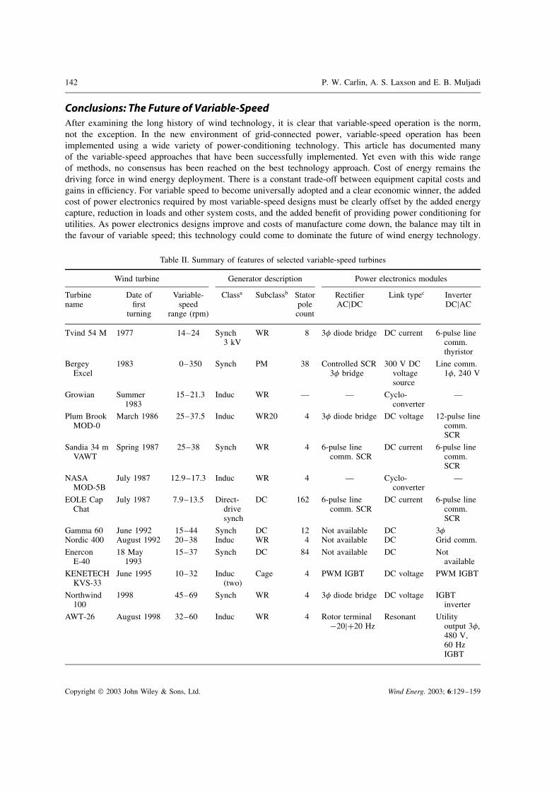
Many manufacturers have developed variable-speed machines over the last few decades. There have beenmany production machines and an even greater number of prototypes or proofs of concept. Appendix Aidentifies 13 of these machines, including the combinations of generators and power conversion methods thatallowed them to run in a variable-speed mode. The list is far from complete. We focused here on machinesfor which well-documented public data exist. However, it represents a general cross-section of the differentmethods for allowing variable-speed operation.
In order to allow a quick overview, a chronological list of these turbines is presented in Table II togetherwith a summary of some important features of their drive trains.
Copyright " 2003 John Wiley & Sons, Ltd. Wind Energ. 2003; 6:129–159
142 P. W. Carlin, A. S. Laxson and E. B. Muljadi
Conclusions: The Future of Variable-SpeedAfter examining the long history of wind technology, it is clear that variable-speed operation is the norm,not the exception. In the new environment of grid-connected power, variable-speed operation has beenimplemented using a wide variety of power-conditioning technology. This article has documented manyof the variable-speed approaches that have been successfully implemented. Yet even with this wide rangeof methods, no consensus has been reached on the best technology approach. Cost of energy remains thedriving force in wind energy deployment. There is a constant trade-off between equipment capital costs andgains in efficiency. For variable speed to become universally adopted and a clear economic winner, the addedcost of power electronics required by most variable-speed designs must be clearly offset by the added energycapture, reduction in loads and other system costs, and the added benefit of providing power conditioning forutilities. As power electronics designs improve and costs of manufacture come down, the balance may tilt inthe favour of variable speed; this technology could come to dominate the future of wind energy technology.
Table II. Summary of features of selected variable-speed turbines
Wind turbine Generator description Power electronics modules
Turbinename
Date offirst
turning
Variable-speed
range (rpm)
Classa Subclassb Statorpolecount
RectifierACjDC
Link typec InverterDCjAC
Tvind 54 M 1977 14–24 Synch3 kV
WR 8 3" diode bridge DC current 6-pulse linecomm.thyristor
BergeyExcel
1983 0–350 Synch PM 38 Controlled SCR3" bridge
300 V DCvoltagesource
Line comm.1", 240 V
Growian Summer1983
15–21.3 Induc WR — — Cyclo-converter
—
Plum BrookMOD-0
March 1986 25–37.5 Induc WR20 4 3" diode bridge DC voltage 12-pulse linecomm.SCR
Sandia 34 mVAWT
Spring 1987 25–38 Synch WR 4 6-pulse linecomm. SCR
DC current 6-pulse linecomm.SCR
NASAMOD-5B
July 1987 12.9–17.3 Induc WR 4 — Cyclo-converter
—
EOLE CapChat
July 1987 7.9–13.5 Direct-drivesynch
DC 162 6-pulse linecomm. SCR
DC current 6-pulse linecomm.SCR
Gamma 60 June 1992 15–44 Synch DC 12 Not available DC 3"Nordic 400 August 1992 20–38 Induc WR 4 Not available DC Grid comm.Enercon
E-4018 May
199315–37 Synch DC 84 Not available DC Not
availableKENETECH
KVS-33June 1995 10–32 Induc
(two)Cage 4 PWM IGBT DC voltage PWM IGBT
Northwind100
1998 45–69 Synch WR 4 3" diode bridge DC voltage IGBTinverter
AWT-26 August 1998 32–60 Induc WR 4 Rotor terminal#20jC20 Hz
Resonant Utilityoutput 3",480 V,60 HzIGBT
Copyright " 2003 John Wiley & Sons, Ltd. Wind Energ. 2003; 6:129–159

Variable-Speed Wind Turbine Technology 143
Table II. (Continued)
a Rotating machine. Either an electric motor or an electric generator (or alternator). Usually, the same machine can functionin either capacity. Synch. A rotating machine employing a rotor carrying a source of constant magnetic field, either frompermanent magnets or from a winding connected to a source of direct current. When such a machine is connected toa utility grid either as a motor or a generator, the ratio of the grid AC frequency to the machine rotational speed is atall times a constant independent of load. Induc. An induction rotating machine. A rotating machine whose principle ofoperation depends on induced voltages caused by the relative motion between the spinning magnetic field in the air gapand conductors on the spinning mechanical rotor. The departure of the rotor speed from synchronous speed expressed asa percentage of synchronous speed is called slip. Comm. A rotating machine (either AC or DC) that transfers energy toor from the spinning rotor by means of a segmented commutator and brushes. This combination usually functions as amechanical rectifier.b Cage. Cage or squirrel cage describes the construction of the rotor of the traditional induction machine. A cylinder ofsoft iron has bars of good conducting metals embedded in its surface and parallel to its axis of rotation. These bars areall electrically connected together by being welded to conducting rings at either end of the rotor cylinder. No externalelectrical connections are made to it. WRnn. The wound rotor is an alternative to the more common cage rotor of inductionrotating machines. The numerals (nn) that follow the WR designator (when present) give the maximum percentage of thefull load power of the induction machine that must be handled by the associated power electronics. DC. The traditionalsynchronous rotating machine has a rotor equipped with coils of wire wound on soft iron cores, and usually fed fromslip rings. When these coils are supplied with direct current, they produce constant radial magnetic fields alternating inpolarity around the circumference of the rotor. The number of magnetic poles is made to be the same as the poles ofthe corresponding stator. The surface of the rotor may be either perfectly cylindrical (round rotor) or supporting radicallyprojecting pole pieces called salient poles. PM. To simplify the design of the traditional synchronous rotating machine,a system of permanent magnets can be substituted for the rotor field windings. The resulting generator starts to developvoltage as soon as the rotor starts to turn. Because the field strength is not adjustable, these machines cannot readilycontrol reactive power flow.c DC voltage. The voltage on the direct current bus for transferring energy from the generator rectifier to the inverterthat feeds the utility is controlled to a constant value. It is characterized by the presence of a capacitor across the bus.The current in this link depends on demand. DC current. The current in the direct current bus for transferring energyfrom the generator rectifier to the inverter that feeds the utility is controlled to a constant value. It is characterized bythe presence of an inductor in series with the bus. The voltage on the bus is not controlled. Cycloconverter. A system ofpower electronic switches that in effect directly convert the frequency and voltage of the source energy to the frequencyand voltage needed by the load. In principle, this is done by synthesizing the output waveform from thin time slices ofthe input energy source. Thus the system cannot be meaningfully decomposed into rectifier, link and inverter modules.Resonant. If the link between the electronics of the variable-speed source and the inverter that supplies the load is formedfrom appropriately connected inductors and capacitors, then current in the link is caused to consist of one or moresinusoidal oscillations. The advantage of this arrangement is that, by proper timing, switching can occur at instants ofzero voltage (ZVS) and/or zero current (ZCS).
A quick review of the preceding history of wind energy technology shows that wind energy engineers anddesigners have long been aware of the implicit natural difficulty of matching a wind-driven prime moverto a utility-connected electric generator. A century of electric technology development has yielded electricmachines with outstanding energy conversion efficiency but which are optimized to operate at exactly onespeed. On the other hand, wind-driven machines, whose power is based on the lift derived from aerofoils,have optimal performance when their angle of attack is relatively constant near a known optimum value. Forthis to be true for a wind turbine aerofoil, the optimal rotor speed must be proportional to the impinging windspeed, an entity well known for its variability.
As the preceding material has shown, there has been a remarkable diversity of solutions offered to amelioratethis mismatch. So far, rather than modifying mechanical transmissions or designing novel types of electricgenerators, system designers have coupled the variable electrical energy from traditional generators to theclient utility through a great variety of power electronics networks. The elements chosen to comprise suchnetworks have depended on the state of the electronics art at the time the system was built. Early on, whenonly silicon-controlled rectifiers (SCRs) were available, six- and 12-pulse inverters were employed with theirconcomitant poor current waveform. As the variety of more efficient and faster switches grew, other circuittopologies were selected to capitalize on the then current state of the art. An important guiding example for
Copyright " 2003 John Wiley & Sons, Ltd. Wind Energ. 2003; 6:129–159
144 P. W. Carlin, A. S. Laxson and E. B. Muljadi
wind system designers has been the swift improvement of large adjustable-speed motor drives (ASDs), whichwere developed in response to a rapid rise in demand from industry.
Would it be foolhardy to forecast the next level of development? At this point, global technology is oftenmodelled as two parallel and mutually dependent streams, namely software and hardware. New hardwareoptions based on novel electronic circuits and rapidly improving components promise an ever-widening fieldof possible approaches, while the state-of-the-art hardware found in the variety of emerging wind turbinesopens an opportunity for wind turbine software innovation. The field now seems ripe for an exhaustive searchfor control schemes, with the goal of finding those that can simultaneously maximize both performance andequipment lifetime.
As in all technologies, the future is difficult to predict. Concepts borrowed from other fields or otherapplications could have profound effects on future designs. Clearly, there are bound to be surprising changesin variable-speed architectures in the coming years.
AcknowledgementsIn assembling such a history, no single author or source possesses all the necessary information. The authorswould like to acknowledge input and feedback from the following.
The Wind Industry and Academia
Mr Steve Atkins, The Wind Turbine Co.Mr Elliott Bayly, World Power TechnologiesMr Mike Bergey, Bergey WindpowerDr Jamie Chapman, OEM Development CorporationMr Clint (Jito) Coleman, Northern Power SystemsDr Edgar DeMeo, ConsultantDr Tom Lippo, University of WisconsinDr Andrew Swift, UTEPMr Claus Weigand, Electronic Power Conditioning, Inc.
The National Laboratories
Ms Al Berger, NRELMr Sandy Butterfield, NRELDr Henry Dodd, SandiaMr Lee J. Fingersh, NRELDr Robert Thresher, NREL
General references concerning Adjustable Speed Drives1. Novotny DW, Lipo TA. Vector Control and Dynamics of AC Drives. Oxford Science Publications: Oxford, 1997.2. Hasse K. On the dynamic of speed control of a static AC drive with a squirrel cage induction machine. PhD Dissertation,
Technischa Hochschule, Darmstadt, 1969.3. Blashke F. The principle of orientation—the basis for the transvector control of three-phase machines. Siemens
Zeitschrift 1971; 45: 757–760.4. Krause PC. Analysis of Electric Machinery. McGraw-Hill: New York, 1986.5. Mohan N, Undeland TM, Robbins WP. Power Electronics, Converters, Applications, Design . Wiley: New York, 1989.6. Lipo TA. Variable speed generator technology options for wind turbine generators. Wisconsin Electric Machines and
Power Electronics Consortium, Research Report 84-4, 1984.7. Caroll DP, Krause PC. Security assessment of power systems including energy storage and with the integration of wind
energy. Progress Report for Period July 1, 1981–September 30, 1981, The United States Department of Energy, underContract No. DE-AS02-77ET 29 100 (Formerly EC-77-S02-4206), 1981.
Copyright " 2003 John Wiley & Sons, Ltd. Wind Energ. 2003; 6:129–159

Variable-Speed Wind Turbine Technology 145
8. Meritt BT. An asynchronous AC/DC/AC link for wind power application. PhD Thesis, University of Wisconsin-Madison, 1977.
9. Reitan DK. A wind powered asynchronous AC/DC/AC converter system. NASA/NSF Workshop Proceedings NSF/RA/W-73-066; 109–114.
Appendix A: Short Descriptions of 13 Variable-Speed Wind TurbinesA1. The Danish Machine at TvindHistoryIn spring 1975 a boarding school in the village of Tvind near Ulfborg in the Jutland region of Denmarkdecided to construct and install a large wind turbine. Some of the reasons for this were that the project wouldprovide the students with practical experience to supplement their theoretical classes, the energy would bea hedge against the expected rise in heating oil prices, and the idea fitted with the school’s philosophy ofdecentralization. As this was early in the present era of wind turbine development, several ideas for the designof the machine were considered, found unsatisfactory and dropped. For example, it had been intended initiallyto supply supplementary heat to the school buildings by circulating water heated from a wind turbine-drivenchurn. A conventional generator with eddy current brake for heating water piped to the nacelle was alsorejected. Next, a direct-coupled, 48-pole synchronous generator was being considered for electrical heating.However, at this point an eight-pole, 2200 kVA, synchronous generator and a 1200 kW gearbox becameavailable at a reasonable price. Further consideration revealed that, although all the wind machine energycould be used for heating in the winter, in the summer there would be an energy surplus.
Eventually it was decided that some of this power should be sold to the electric utility. Direct synchro-nization of the eight-pole generator to the utility was not indicated for several reasons. For example, the20 km (12"3 mile) utility distribution line was very weak. The transmission gear ratio was not optimal for thewind regime at synchronous speeds, and the turbine blades were limited to a narrow range of tip speed ratiosfor dynamic reasons. Therefore it was finally decided to connect to the electric utility through a frequencyconverter. This alleviated many of the above considerations and would allow for variable-speed operation.
ConfigurationAs finally built, the Tvind school’s machine was provided with a three-bladed, downwind rotor having a54 m (177 ft) diameter. The blade material was glass fibre-reinforced epoxy of 4700 k (10,364 lb) mass perblade. The three-bladed rotor implied a rigid hub, which was at a height of 53 m (174 ft) on a concrete tower.Full-span pitch as well as the torque from the generator controlled the machine. The variable rotor speedranged from 14 to 24 rpm.
Although the generator was capable of more, the machine was rated at 900 kW. In keeping with itsoriginal purpose of providing space heating for the school, output power could be switched either to a1600 m3 (56,503 ft3) water reservoir or to classroom radiators. At the same time, some power was directedto a 400 kW rectifier/inverter. For medium winds, heating power was held constant, the frequency convertertook up the remaining varying power.
The three-phase generator at rated power provided 3300 V at the output, which was transformed down to400 V for the frequency converter. Six bridge-connected, solid state thyristors rectified this power onto theconstant-current DC bus, which had inductors on both the positive and negative sides. This DC energy wasinverted using six more thyristors under six-pulse phase control. This 50 Hz output was then transformed upto 10,000 V for injection into the utility distribution line. Filters were installed between the inverter and theoutput transformer. Their twofold purpose was to attenuate the fifth and seventh harmonics from the six-pulseinverter and to supply some compensation for reactive power. This filter was able to provide 200 kVA ofreactive compensation. The frequency converter was designed and built by 12 students in a special coursegiven by The Laboratory of Electric Circuits and Machines at The Technical University of Denmark.
In approximately 50,000 h of operation, this machine supplied about 1000 MWh of electric energy peryear. By early 1993 the machine’s rotor had accumulated over 53 million revolutions. In 1997 it celebratedits 20 year anniversary
Copyright " 2003 John Wiley & Sons, Ltd. Wind Energ. 2003; 6:129–159

146 P. W. Carlin, A. S. Laxson and E. B. Muljadi
Literature1. Krabbe U. The electric power equipment for the windmill in Tvind. In Implementing Agreement for
Co-operation in the Development of Large Scale Wind Energy Conversion Systems: Second Meeting ofExperts—Control of LS-WECS and Adaptation of Wind Electricity to the Network , Meggle R, Windheim R(scientific co-ordinators). Zentralbibliothek der Kernforschungsanlage Julich GmbH: 1979; 25–30.
2. IEA Wind Energy Annual Report for 1993 . NUTEK: Stockholm, 1993; 36.
A2. Bergey ExcelHistoryThe Bergey Windpower Company, headquartered in Norman, Oklahoma, marketed its first variable-speed,utility-connected wind turbine in 1980. In 1983 the larger, 10 kW Excel wind turbine was offered, and inabout 5 years over 300 machines had been installed, usually on farms and ranches. The standard grid-tiedinstallation featured the Excel turbine, a power electronics unit that converted the variable-voltage, variable-frequency alternating current (‘wild AC’) to direct current and from there back to utility alternating current.This is the classical AC–DC–AC system.
ConfigurationThe Excel aerodynamic rotor with its three fixed blades is attached directly to the generator rotor. Becausethis rotor carries the permanent magnet excitation for the generator, the stator windings can be stationary andmounted on the wind machine frame, thereby obviating the need for slip rings. The fibre-reinforced plasticblades are flexible around their longitudinal axes. This feature, together with special pitch weights at theoutboard leading edges, causes a change in pitch angle as rotor speed increases. Thus the relatively highangle at standstill provides higher starting torque; and, as rotor speed increases, the blades deflect towardsflatter pitch, thereby allowing a higher tip speed ratio.
The twofold function of all wind turbine control systems is to harvest maximum wind energy in normaloperation and to protect the machine from damage in winds above rated power. For the latter requirement theExcel can capitalize on its furling control. Although its rotor is 7 m (23 ft) in diameter, it is still practical toorient this machine into the wind by using a tail. By design, the horizontal axis of rotation of the turbine rotordoes not intersect the vertical yaw axis of the whole machine. When the wind speed approaches dangerousvalues, the preceding axis offset causes the rotor generator combination to yaw out of the wind, and themachine slows to moderate speeds. This yawing is possible because the tail is hinged to the main machinebody. However, the hinge axis is inclined to the vertical, so that as soon as the excessive wind gust haspassed, a gravitational restoring moment exists that returns the machine to its operating configuration.
To match the incoming wild three-phase AC power from the 38-pole permanent magnet generator to asingle-phase utility line, a half-controlled, three-phase bridge is paired with a voltage-source line-commutatedinverter. The SCRs in this bridge permit the control system to control the voltage level on the linking DCbus and thus to control the charge level of any batteries connected to it. The second purpose of this DC busis to provide power to the voltage-source inverter power electronics, which feeds power into the utility. Onceagain, the switches provided in this element are SCRs.
Literature1. BWC Excel-R Windpower Generator Owner’s Manual and Parts List . Bergey Windpower Company, Inc.:
Norman, OK, 1983.
A3. The Growian Variable-Speed Wind TurbineHistoryOne of the first very large prototype wind turbines was initiated by funding provided by the Federal Republicof Germany in 1977/1978. At the end of the 1970s, three German utilities formed Growian GmbH, a companywhose purpose was to specify, design, build and test a large-scale wind energy conversion system (LS-WECS).
Copyright " 2003 John Wiley & Sons, Ltd. Wind Energ. 2003; 6:129–159
Variable-Speed Wind Turbine Technology 147
The name was derived from Grosse Windenergie-Anlage or Large Wind Energy Plant. The resulting 3000 kWturbine was advanced for its time, in that it featured a variable-speed drivetrain with power electronicsand a 100 m (328 ft) teetered rotor with full-span pitch. In 1979 the designers set up a trade-off betweena synchronous generator with a frequency converter in the stator circuit and a doubly fed asynchronous(induction) machine with a frequency converter in the rotor circuit. The doubly fed system was chosen.
The wind machine test station at Kaiser-Wilhelm-Koog in northern Germany was chosen for the installationlocation. During October 1982 the nacelle with its two-bladed rotor attached was raised to the top of its 100 m(328 ft) tower. Regular testing began during the summer of 1983, which yielded confirmation of the predictedpower curve and power coefficient. The machine responded well to the control system, and no vibrations orresonances were observed. Testing continued through the spring of 1987.
Early in the testing, cracks developed in the material of the highly stressed parts of the hub. Repairingthese problems caused extended periods of downtime. After a total of 500 h of intermittent operation it wasdecided to end the tests in August 1987. It was dismantled during summer 1988.
The data archived during the testing year have been thoroughly analysed under the management ofIndustrieanlagen-Betriebsgesellschaft mbH, which tested a full Growian rotor blade in the early 1980s. Thisinformation has been valuable for the design of subsequent machines such as the WKA 60.
Configuration
To summarize, the Growian was a 3 MW, variable-speed, downwind machine on a 100 m (328 ft) concretetower. The 100 m (328 ft), teetered, two-bladed rotor was fabricated from glass fibre around a steel spar.From the cut-in wind speed of 6"3 m s#1 (14 mph) up to the rated wind speed of 11"8 m s#1 (26 mph) thecontrol system attempted to hold optimum tip speed ratio. Full-span pitch allowed power limitation to 3 MWfor winds up to the cut-out speed of 24 m s#1 (53 mph). The nacelle mass was 240 t (529 000 lb) and itsorientation (yaw) was actively controlled. The rotor speed could vary between 15"73 and 21"28 rpm.
Three modes of operation were initially considered. The first was to use a simple direct connection of anasynchronous generator with DC field excitation to the utility (essentially constant-speed operation). Computersimulations of output power fluctuations in turbulent winds immediately ruled out this mode. The two othermodes considered permitted variable rotor speed and therefore the possibility for maximum power tracking.One mode used the just-described synchronous generator, but fed its entire output to an AC–DC–AC chainconsisting of a rectifier, a DC bus and an inverter to the grid. However, the mode finally chosen was to usea synchronous generator with a three-phase slip ring-fed rotor (essentially a wound-rotor induction machine).The rotor was fed using field orientation techniques from a power electronic frequency converter. Recall thatfield orientation uses control of phase and amplitude of the generator rotor excitation to set real and reactivepower output to the utility independently of each other. In spite of the slight additional cost, this was thesystem that was built and installed. The system has since been used as a model for many wind turbines.
Literature
1. Leonard W. Field oriented control of a variable speed alternator connected to the constant frequency line.In Implementing Agreement for Co-operation in the Development of Large Scale Wind Energy ConversionSystems: Second Meeting of Experts—Control of LS-WECS and Adaptation of Wind Electricity to theNetwork , Meggle R, Windheim R (scientific co-ordinators). Zentralbibliothek der KernforschungsanlageJulich GmbH: Julich, 1979.
2. Warneke O. Application of a double-fed asynchronous generator in the Growian wind power plant.Windkraft Journal 1985; 5: 164–166.
3. Warneke O. Use of a double-fed induction machine in the large GROWIAN wind energy converter. SiemensEnergietech 1983; 5: 364–367.
4. Koerber F. Final plans for the construction of GROWIAN. Interim Final Report , Bundesministerium furForschung und Technologie, Bonn, 1980; 89.
5. IEA Wind Energy Annual Report for 1988 . NUTEK: Stockholm, 1988; 30–31.
Copyright " 2003 John Wiley & Sons, Ltd. Wind Energ. 2003; 6:129–159

148 P. W. Carlin, A. S. Laxson and E. B. Muljadi
A4. NASA MOD-0 Plum Brook
HistoryThe experimental wind turbine erected at the Plum Brook Station of the NASA Lewis Research Center nearSandusky, Ohio, holds an important place in the recent history of wind energy in the United States. Thesudden rise in fuel costs during the 1970s precipitated the federal wind energy programme, the administrationof which was assigned to the Energy Research and Development Administration. One component of theprogramme was directed towards investigating large (>100 kW) wind turbines. This was the origin of the‘MOD’ series of wind machines that eventually culminated in the MOD-5B machine in Hawaii (described inAppendix A6).
The design and fabrication of the first of this series, the MOD-0, was assigned to the NASA Lewis ResearchCenter (LeRC) in Cleveland, Ohio. The LeRC Plum Brook field-testing facility 60 miles west of Clevelandand just outside Sandusky, Ohio, had available space and moderate annual wind and so was chosen forthe test site. The first iteration of this family was analysed, designed, fabricated and erected in 18 months.The nacelle was placed atop its 30 m tower on 3 September 1975. The machine achieved an 80 kW outputat 30 rpm on 23 October 1975. Not surprisingly for a prototype machine, over the next 11 years, manytransformations of the original design were conceived and tested. For example, the tower shadow created bythe original lattice tower and its open stairway precipitated the substitution of a tubular steel tower. To addexperimental flexibility, this tower was mounted on elastic footings with adjustable spring constants in orderto study resonances. Many different rotors were tested, including a single blade with a counterbalance.
ConfigurationThe original 100 kW synchronous generator was driven by a 45 : 1 gear ratio transmission and a 30 m (125 ft),two-bladed, downwind, rigid-hub, full-span pitch-controlled rotor. Rated power of 100 kW was achieved ata constant 40 rpm with a wind of about 8 m s#1 (17"7 mph). Eleven years later in 1985, after many data setsfrom many interesting modifications had been analysed, the configuration for the final test appeared.
The equipment for this variable-speed test had evolved to a 200 kVA wound-rotor induction motor fabricatedby the Bogue Electric Manufacturing Company. It was driven through the original transmission with an addedV-belt coupling of step-up ratio 1"28 : 1. This drivetrain was driven by two 14"3 m (47 ft) teetered woodenblades, each with 2 m of pitchable tips. The three-phase generator stator was connected directly to the utility.The generator rotor winding was connected to the utility through a cycloconverter custom designed by theWestinghouse Electric Corporation. Because the cycloconverter could supply variable low-frequency, three-phase voltage to the generator rotor with either phase rotation, the system could operate either above, below orat synchronous speed. Theoretically, this 0–45 Hz voltage range supplied by the cycloconverter could allowthe system to turn at speeds from 450 to 3150 rpm. However, owing to transformer voltage and generatormechanical load limitations, operation was limited to between 1440 and 2160 rpm. For less-than-rated windsthe control system regulated system speed by controlling generator torque and attempted to match electricalpower to the utility to the power available in the wind at that instant. When the wind power exceeded ratedvalue for the machine, the controller shifted to a constant-power-output algorithm and controlled speed bypitching the blade tips.
To facilitate comparison of this variable-speed operation with an equivalent constant-speed system, thegenerator rotor could be switched from the cycloconverter to a set of resistors. This caused the generator tobecome, in effect, a squirrel cage induction machine with slip of about 5%.
As a by-product of the analysis performed by the control system, it was possible to supply reactive powerto the interconnected utility. This feature could help support voltage on power distribution lines if requestedby the utility.
Literature1. Herrera JI, Reddoch TW. Testing requirements for variable speed generating technology for wind turbine
applications. Electric Power Research Institute (EPRI) AP-4590, Project 1996-22, Final Report, 1986.
Copyright " 2003 John Wiley & Sons, Ltd. Wind Energ. 2003; 6:129–159

Variable-Speed Wind Turbine Technology 149
2. McDade J, Ziemke R, Schmidt W. Variable speed system testing on the MOD-0 wind turbine. SverdrupData Report (Internal Solar Energy Research Institute (SERI) Report), 1986.
3. Herrera JI. Reddoch TW, Lawler JS. Experimental investigation of a variable-speed, constant-frequencyelectric generating system from a utility perspective. DOE/NASA/4105-1, NASA CR-174950 , 1985.
4. Herrera JI, Reddoch TW. Analysis of the electrical characteristics of a Westinghouse variable speedgenerating system for wind turbine applications. SERI/STR-217-3133, DE88001139 , 1988.
A5. DOE/Sandia National Laboratories/US Department of Agriculture 34 m, Vertical-axisVariable-Speed Test Bed
HistoryDesign of the 34 m vertical-axis wind turbine (VAWT) was begun in 1984 by Sandia engineering staff. Designrequired approximately 2 years. Ohio State University provided aerodynamics design support. Fabrication andassembly of components required approximately 1 year. The machine was installed at the USDA test site inBushland, Texas, near Amarillo, and was dedicated in spring 1987. The machine included the first laminarflow, stall-regulated aerofoils for wind turbines. At the time the blades were the largest multivoid extruded-aluminium aerofoils ever built. The machine remained in operation from 1987 until its final decommissioningin June 1998.
ConfigurationThe machine consisted of a 34 m (121 ft) diameter rotor with a height-to-diameter ratio of 1"25. The rotortop was 50 m (164 ft) above ground level. The rotor bottom was 7 m (23 ft) above ground level. The bladeswere 56 m (184 ft) in length, using a stepped tapered-blade design, and were stall regulated. The centralaluminium support tube was 3 m in diameter, 12"5 mm thick, and supported at its upper end by three pairsof 63 mm steel bridge strand cables at an angle of 35° to the ground. The rotor, which drove a 700 kWtransmission, was rated at 500 kW at 37"5 rpm in a 12"5 m s#1 (28 mph) wind. The turbine ran at variablespeed between 25 and 38 rpm.
Power generation was accomplished through a 625 kW-rated synchronous generator. The generator wascapable of operating between 288 and 1900 rpm. Variable-speed operation was accomplished with a current-source load-commutated inverter, also known as a DC current-link frequency converter. This providedAC–DC–AC conversion.
Literature1. Klimas PC, Dodd HM, Clark RN. An overview of the DOE/Sandia/USDA vertical axis wind turbine test
bed. AWEA WindPower ’87 Proceedings, 1987; 35–40.2. Ralph ME. Control of the variable speed generator on the Sandia 34-metre vertical axis wind turbine.
AWEA WindPower ’89 Proceedings, 1989; 99–104.3. Ralph ME. A model of the 34-m VAWT variable speed generator control system. Ninth ASME Wind Energy
Symposium, presented at the thirteenth annual Energy-Sources Technology Conference and Exhibition, NewOrleans, January 14–18, 1990; 189–190.
A6. NASA MOD-5B Wind Turbine SystemHistoryThe MOD-5 programme was originally conceived in 1980, and drew significantly on the MOD-0 and MOD-2programmes. It was funded by DOE and managed by the Wind Energy Project Office of the NASA LewisResearch Center. The machine was installed at Kahuku Village, Oahu, Hawaii, and was first operational inJuly 1987. Early in 1988, operation of the turbine was transferred to Hawaiian Electric Incorporated. Lateroperation of the turbine passed to Makani Uwila Power Corporation (MUPC) and the machine was kept inservice intermittently until late in 1996. At that time, owing to financial difficulties, the machine was shut
Copyright " 2003 John Wiley & Sons, Ltd. Wind Energ. 2003; 6:129–159

150 P. W. Carlin, A. S. Laxson and E. B. Muljadi
down along with the rest of MUPC, all property of which passed to the property owner, Campbell Estates.With no prospects for continued operation of the machine, Campbell Estates decided to disassemble and scrapthe machine. Prior to this decommissioning, DOE/NREL salvaged the drivetrain gearbox and generator inJuly 1998.
ConfigurationThe turbine consisted of a 97"5 m (320 ft) diameter, two-bladed rotor, with welded-steel blades, incorporatingpartial-span hydraulic pitch regulation, in which the outer 16"8 m (55 ft) of each blade could be controlledto limit rotor torque. Operation included an upwind teetered rotor, a hydraulically driven yaw system and a103 : 1 step-up planetary gearbox to drive a wound-rotor generator. The nacelle was set atop a welded 58"2 m(191 ft) tubular tower, with a 61 m (200 ft) hub height. Cut-in wind speed was 5"4 m s#1 (12 mph), withcut-out at 27 m s#1 (60 mph). Rotor rpm varied from 12"9 to 17"3.
Power generation was accomplished with a four-pole, three-phase, 60 Hz, 4160 V, wound-rotor inductiongenerator with secondary power recovery. The generator had a 3"5 MVA rating. Normal variable-speedoperating ranges ran from 1330 to 1780 rpm. The generator had a dynamic speed range capability of1250–1880 rpm, with a maximum survival speed of 2270 rpm.
Variable speed and secondary power recovery were accomplished by a cycloconverter. This arrangementprovided for AC–AC variable-speed operation. The rotor was allowed to vary in rpm within a limitedrange. The thyristor switches within the cycloconverter were programmed to provide vector control of theair gap field. The switches were provided with a reference waveform for each generator phase (the gridfrequency). The result of this method was a very rough waveform for each of the rotor phases. Extensivefiltering was necessary to produce an acceptable system output meeting IEEE-519 requirements. Introductionof IGBTs and other sophisticated high-power electronic switches allows for much-improved implementationof this technology.
Literature1. MOD-5B wind turbine system final report, Volume II, Detailed report. NASA CR-180897, 1988.2. MOD-5B wind turbine system concept and preliminary design report. NASA CR-168047, 1982.3. Spera DA, Miller MW. Performance of the 3"2 MW MOD-5B horizontal axis wind turbine during
55 months of commercial operation in Hawaii. AWEA WindPower ’92 Proceedings, 1992; 231–238.
A7. The Vertical-axis Variable-Speed EOLE at Cap Chat, CanadaHistoryIn the early 1980s, Hydro-Quebec and the National Resource Council of Canada began a joint venture todevelop a large-scale Darrieus turbine (VAWT). In 1983 a preliminary design was completed. By the endof 1984, detailed design and fabrication subcontracts were awarded. Erection of the machine was finallycomplete by November 1986. Rotor fabrication was performed by Versatile Vickers shipyard in Montreal andshipped to the site by barge. The machine was sited near the village of Cap Chat, in Quebec Province, on thesouth shore of the St Lawrence River. This site was chosen for its 8"5 m s#1 (18"9 mph) wind speed averageat 60 m (197 ft), which represents rotor mid-height.
First rotation and grid coupling occurred in July 1987. The machine was commissioned in August ofthe same year and became fully operational in March 1988. The machine operated regularly under operatorsupervision from 1988 until 1993, when it was shut down owing to failure of the bottom bearing. During the5 years of operation the machine was run at power levels of up to 2"7 MW. During its lifetime it produced12,740 MWh in 18,600 h of operation. Over this period it maintained an availability of approximately 94%.
ConfigurationThe EOLE machine was a vertical-axis wind turbine 96 m (344 ft) in height. Its equatorial diameter was64 m (210 ft), with a swept area of 4000 m2 (43,055 ft2). Two blades were employed in the design, usingNACA 0018 aerofoils of 2"4 m (7"9 ft) chord. The machine was designed as a direct-drive variable-speed
Copyright " 2003 John Wiley & Sons, Ltd. Wind Energ. 2003; 6:129–159

Variable-Speed Wind Turbine Technology 151
machine. The generator was 12 m (39"37 ft) in diameter, and power conversion was achieved using a static-frequency converter with power factor controls. The rated speed was 14"25 rpm with a maximum poweroutput of 3"8 MW. Designed cut-in wind speed was 5"5 m s#1 (12"2 mph) and cut-out wind speed was20 m s#1 (44"5 mph). However, these operational speeds and power output were not attained in operationowing to structural resonances that were discovered during checkout. The final schedule that was selectedcombined variable-speed operation with constant-speed operation according to the average wind. For windsfrom 6"5 to 8 m s#1 (14"5–17"8 mph) the machine ran in variable-speed mode from 7"9 to 9"8 rpm. Forwinds between 8 and 11"5 m s#1 (17"8–25"6 mph) the power electronics governed the machine to a constantspeed of 11"35 rpm. Similarly, above 11"5 m s#1 (25"6 mph) the machine was governed to a constant speedof 13"5 rpm. The machine did operate up to 13"5 rpm with a cut-out wind speed of 17 m s#1 (37"8 mph).Data acquisition systems were developed built upon VAWT software from Sandia National Laboratories.
Literature1. IEA Large-Scale Wind Energy Annual Report for 1987 . NUTEK: Stockholm, 1987; 11–15.2. IEA Large-Scale Wind Energy Annual Report for 1993 . NUTEK: Stockholm, 1993; 31.
A8. The Gamma 60 Variable-Speed Wind TurbineHistoryIn October 1986, ENEA (the Italian National Committee for Research and Development of Nuclear andAlternative Energies) signed a cooperative agreement with the Aeritalia–FIAT Aviazione for Wind EnergyConsortium for the design and fabrication of a large, 60 m (197 ft), horizontal-axis wind turbine rated at1500 kW. Funding was supplied from ENEA, the European Commission and some other Italian organizations.The next March, ENEL (the Italian National Electricity Board) placed an order for the machine with Aeritalia,which acted as the prime contractor in the consortium. This prototype turbine was erected at the windenergy test site in the northwest corner of Sardinia. Prominent in the specifications was the requirement forbroad-range variable speed (15–44 rpm), as well as teetering hub, fixed pitch, and power regulation throughyaw control.
ConfigurationThe blade design was based on the WTS-4 blades made by Hamilton Standard. This allowed the sameequipment to be used for the Gamma 60 machine. Some modifications, such as shortening the blades andinstalling an internal bulkhead-type rib (to reduce the centrifugal loads due to air pressure at high speeds),were agreed upon. The rotor was designed to withstand runaway speeds in case of loss of utility or generator.
The 1"5 m (4"9 ft) low-speed shaft disc brake was designed to be able to stop the machine from excessivespeed or from some other emergency. The two-stage epicyclical gearbox has a gear ratio of 33 : 1.
A direct current link is used between the generator rectifier and the utility inverter, because that type offrequency converter provides the required width of speed range, excellent torque control, and electric dampingof structural modes.
The control algorithm chosen had the usual two operating regions. In the first, which is commonly calledregion two, the control system attempts to maintain rotor speed proportional to the existing wind and therebyhold a constant tip speed ratio. The second region, commonly called region three, is where power starts toexceed the rating of the turbine, so that speed must be limited aerodynamically. In this case, this is done byyawing. Unusual, however, for the Gamma 60 is another short region between the two already mentioned.In this region the drivetrain torque limit has been reached; however, the generator and drivetrain power limithas not been reached. The control algorithm then allows the torque to decrease by a small amount. Theresulting rotor acceleration allows more power to be transferred until the generator power limit is reached.At this point, operation at the resulting higher-than-optimum tip speed ratio is unimportant, because excesswind power is available anyway.
The power electronics is also capable of driving the generator as a motor. Accordingly, the gearbox wasconstructed to transmit torque in either direction.
Copyright " 2003 John Wiley & Sons, Ltd. Wind Energ. 2003; 6:129–159
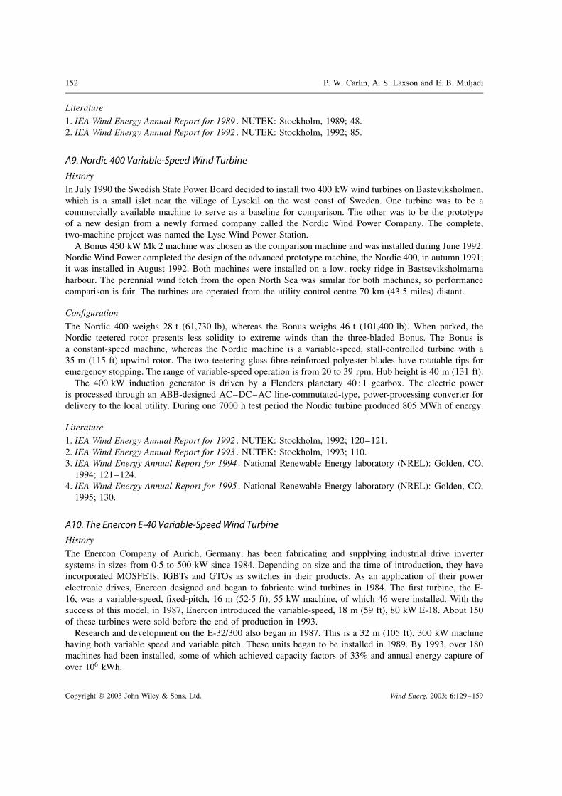
152 P. W. Carlin, A. S. Laxson and E. B. Muljadi
Literature1. IEA Wind Energy Annual Report for 1989 . NUTEK: Stockholm, 1989; 48.2. IEA Wind Energy Annual Report for 1992 . NUTEK: Stockholm, 1992; 85.
A9. Nordic 400 Variable-Speed Wind Turbine
HistoryIn July 1990 the Swedish State Power Board decided to install two 400 kW wind turbines on Basteviksholmen,which is a small islet near the village of Lysekil on the west coast of Sweden. One turbine was to be acommercially available machine to serve as a baseline for comparison. The other was to be the prototypeof a new design from a newly formed company called the Nordic Wind Power Company. The complete,two-machine project was named the Lyse Wind Power Station.
A Bonus 450 kW Mk 2 machine was chosen as the comparison machine and was installed during June 1992.Nordic Wind Power completed the design of the advanced prototype machine, the Nordic 400, in autumn 1991;it was installed in August 1992. Both machines were installed on a low, rocky ridge in Bastseviksholmarnaharbour. The perennial wind fetch from the open North Sea was similar for both machines, so performancecomparison is fair. The turbines are operated from the utility control centre 70 km (43"5 miles) distant.
ConfigurationThe Nordic 400 weighs 28 t (61,730 lb), whereas the Bonus weighs 46 t (101,400 lb). When parked, theNordic teetered rotor presents less solidity to extreme winds than the three-bladed Bonus. The Bonus isa constant-speed machine, whereas the Nordic machine is a variable-speed, stall-controlled turbine with a35 m (115 ft) upwind rotor. The two teetering glass fibre-reinforced polyester blades have rotatable tips foremergency stopping. The range of variable-speed operation is from 20 to 39 rpm. Hub height is 40 m (131 ft).
The 400 kW induction generator is driven by a Flenders planetary 40 : 1 gearbox. The electric poweris processed through an ABB-designed AC–DC–AC line-commutated-type, power-processing converter fordelivery to the local utility. During one 7000 h test period the Nordic turbine produced 805 MWh of energy.
Literature1. IEA Wind Energy Annual Report for 1992 . NUTEK: Stockholm, 1992; 120–121.2. IEA Wind Energy Annual Report for 1993 . NUTEK: Stockholm, 1993; 110.3. IEA Wind Energy Annual Report for 1994 . National Renewable Energy laboratory (NREL): Golden, CO,
1994; 121–124.4. IEA Wind Energy Annual Report for 1995 . National Renewable Energy laboratory (NREL): Golden, CO,
1995; 130.
A10. The Enercon E-40 Variable-Speed Wind Turbine
HistoryThe Enercon Company of Aurich, Germany, has been fabricating and supplying industrial drive invertersystems in sizes from 0"5 to 500 kW since 1984. Depending on size and the time of introduction, they haveincorporated MOSFETs, IGBTs and GTOs as switches in their products. As an application of their powerelectronic drives, Enercon designed and began to fabricate wind turbines in 1984. The first turbine, the E-16, was a variable-speed, fixed-pitch, 16 m (52"5 ft), 55 kW machine, of which 46 were installed. With thesuccess of this model, in 1987, Enercon introduced the variable-speed, 18 m (59 ft), 80 kW E-18. About 150of these turbines were sold before the end of production in 1993.
Research and development on the E-32/300 also began in 1987. This is a 32 m (105 ft), 300 kW machinehaving both variable speed and variable pitch. These units began to be installed in 1989. By 1993, over 180machines had been installed, some of which achieved capacity factors of 33% and annual energy capture ofover 106 kWh.
Copyright " 2003 John Wiley & Sons, Ltd. Wind Energ. 2003; 6:129–159
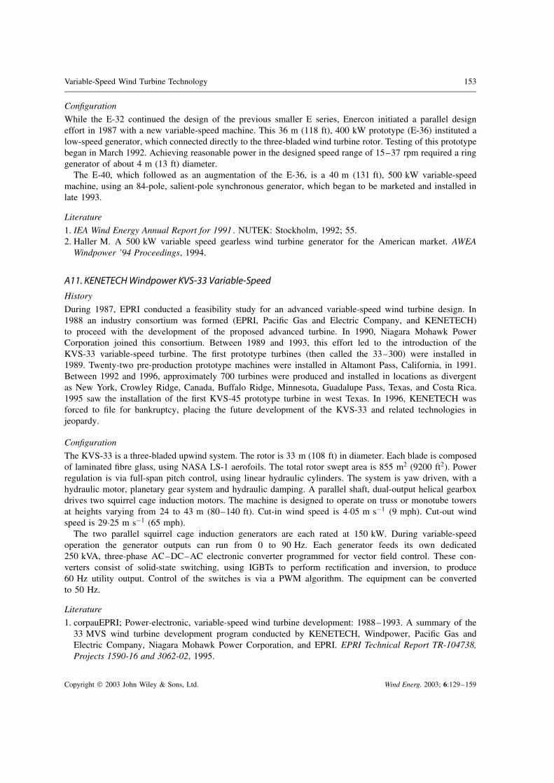
Variable-Speed Wind Turbine Technology 153
ConfigurationWhile the E-32 continued the design of the previous smaller E series, Enercon initiated a parallel designeffort in 1987 with a new variable-speed machine. This 36 m (118 ft), 400 kW prototype (E-36) instituted alow-speed generator, which connected directly to the three-bladed wind turbine rotor. Testing of this prototypebegan in March 1992. Achieving reasonable power in the designed speed range of 15–37 rpm required a ringgenerator of about 4 m (13 ft) diameter.
The E-40, which followed as an augmentation of the E-36, is a 40 m (131 ft), 500 kW variable-speedmachine, using an 84-pole, salient-pole synchronous generator, which began to be marketed and installed inlate 1993.
Literature1. IEA Wind Energy Annual Report for 1991 . NUTEK: Stockholm, 1992; 55.2. Haller M. A 500 kW variable speed gearless wind turbine generator for the American market. AWEA
Windpower ’94 Proceedings, 1994.
A11. KENETECH Windpower KVS-33 Variable-Speed
HistoryDuring 1987, EPRI conducted a feasibility study for an advanced variable-speed wind turbine design. In1988 an industry consortium was formed (EPRI, Pacific Gas and Electric Company, and KENETECH)to proceed with the development of the proposed advanced turbine. In 1990, Niagara Mohawk PowerCorporation joined this consortium. Between 1989 and 1993, this effort led to the introduction of theKVS-33 variable-speed turbine. The first prototype turbines (then called the 33–300) were installed in1989. Twenty-two pre-production prototype machines were installed in Altamont Pass, California, in 1991.Between 1992 and 1996, approximately 700 turbines were produced and installed in locations as divergentas New York, Crowley Ridge, Canada, Buffalo Ridge, Minnesota, Guadalupe Pass, Texas, and Costa Rica.1995 saw the installation of the first KVS-45 prototype turbine in west Texas. In 1996, KENETECH wasforced to file for bankruptcy, placing the future development of the KVS-33 and related technologies injeopardy.
ConfigurationThe KVS-33 is a three-bladed upwind system. The rotor is 33 m (108 ft) in diameter. Each blade is composedof laminated fibre glass, using NASA LS-1 aerofoils. The total rotor swept area is 855 m2 (9200 ft2). Powerregulation is via full-span pitch control, using linear hydraulic cylinders. The system is yaw driven, with ahydraulic motor, planetary gear system and hydraulic damping. A parallel shaft, dual-output helical gearboxdrives two squirrel cage induction motors. The machine is designed to operate on truss or monotube towersat heights varying from 24 to 43 m (80–140 ft). Cut-in wind speed is 4"05 m s#1 (9 mph). Cut-out windspeed is 29"25 m s#1 (65 mph).
The two parallel squirrel cage induction generators are each rated at 150 kW. During variable-speedoperation the generator outputs can run from 0 to 90 Hz. Each generator feeds its own dedicated250 kVA, three-phase AC–DC–AC electronic converter programmed for vector field control. These con-verters consist of solid-state switching, using IGBTs to perform rectification and inversion, to produce60 Hz utility output. Control of the switches is via a PWM algorithm. The equipment can be convertedto 50 Hz.
Literature1. corpauEPRI; Power-electronic, variable-speed wind turbine development: 1988–1993. A summary of the
33 MVS wind turbine development program conducted by KENETECH, Windpower, Pacific Gas andElectric Company, Niagara Mohawk Power Corporation, and EPRI. EPRI Technical Report TR-104738,Projects 1590-16 and 3062-02, 1995.
Copyright " 2003 John Wiley & Sons, Ltd. Wind Energ. 2003; 6:129–159

154 P. W. Carlin, A. S. Laxson and E. B. Muljadi
A12. Northwind 100HistoryDesign of the Northwind 100 began in early 1994 under a design subcontract between CERTEK and theNational Renewable Energy Laboratory Next-generation Innovative Subsystem project. The original designconcept included a permanent magnet direct-drive generator. In 1996, owing to the tragic death of theCERTEK principal (Ed Lucas), CERTEK withdrew from the project, and Northern Power Systems (NPS)assumed responsibility for executing the subcontract. NPS extended its collaborative effort to include theNASA Ames Research Center and the National Science Foundation. This joint collaboration was focusedon developing a high-reliability machine for remote and harsh environments. NPS was ideally suited to thiseffort owing to its long history of providing equipment for deployment at the South Pole and in other marineand cold-weather environments. In 1998 the first of the NW 100 machines was deployed at a Vermont testsite. Future plans include installation of a machine at the National Wind Technology Center for certificationin preparation for applications in Alaska and Antarctica.
ConfigurationThe NW 100 is a 100 kW, three-bladed, upwind variable-speed machine. The unit is direct drive. Thegenerator is a wound-rotor, salient-pole synchronous alternator that was designed by the Westinghouse ElectricCompany. Aerodynamic power is supplied through a 16"6 m (54 ft) stall-controlled rotor with blades providedby LM Glassfiber. Details of the variable-speed drive and control remain proprietary.
Literature1. Migliore P, Calvert SD. U.S. Department of Energy wind turbine development projects. NREL/CP-500-
26151, 1999.
A13. Advanced Wind Turbines AWT-26 Variable-Speed with Doubly Fed GeneratorHistoryThe AWT-26 variable-speed turbine is a modification of the AWT-26/27 configuration developed by AdvancedWind Turbines, Inc. The AWT-26 used the ESI-80, developed by Energy Sciences, Inc., Boulder, Colorado, asa point of departure. Development of the AWT-26 began in 1990 under subcontract to the National RenewableEnergy Laboratory. The first prototype machine was installed in Tehachapi, California, in February 1993.Additional prototypes were installed between 1993 and 1995, culminating in the modified AWT-27.
The AWT-26 variable speed turbine was originally installed at the NWTC in August 1994. In its initialconfiguration, this machine was a standard AWT-26 with a squirrel cage induction generator and a 57 rpmfixed-speed rotor. Beginning in summer 1996, this machine was converted for variable-speed operation undera subcontract with Electronic Power Conditioning, Inc., with AWT as a lower-tier subcontractor. The machineconversion was accomplished by replacing the induction generator with a wound rotor generator and a powerelectronics package allowing variable-speed operations. At the conclusion of testing in 2000 the machine wasconverted back to fixed-speed operation.
ConfigurationThe NWTC AWT-26 is a two-bladed, downwind, free-yaw machine. It includes a 27 m (88"5 ft) teeteredrotor. The blades are of wood composite design and incorporate SERI aerofoils and passive stall control.Rotor control is provided by aerodynamic, electromechanically activated tip brakes. The machine includes aredundant mechanical brake incorporated into the drivetrain which includes a planetary gearbox manufacturedby Flenders. The gearbox incorporates two stages at fixed, specified ratios between 25 : 1 35 : 1. The ratioselected depends upon the rotor diameter and the generator frequencies required. The machine is also providedwith a small mechanical yaw drive for unwinding the droop cable. A PLC controller provides control of themachine. The nacelle sits atop a 24"4 m (80 ft) tubular tower.
Power conversion is accomplished using a 325 kVA, wound rotor generator. This unit operates at 480 Vand a nominal 60 Hz. This is a doubly fed unit in which variable-speed operation is provided by connecting
Copyright " 2003 John Wiley & Sons, Ltd. Wind Energ. 2003; 6:129–159
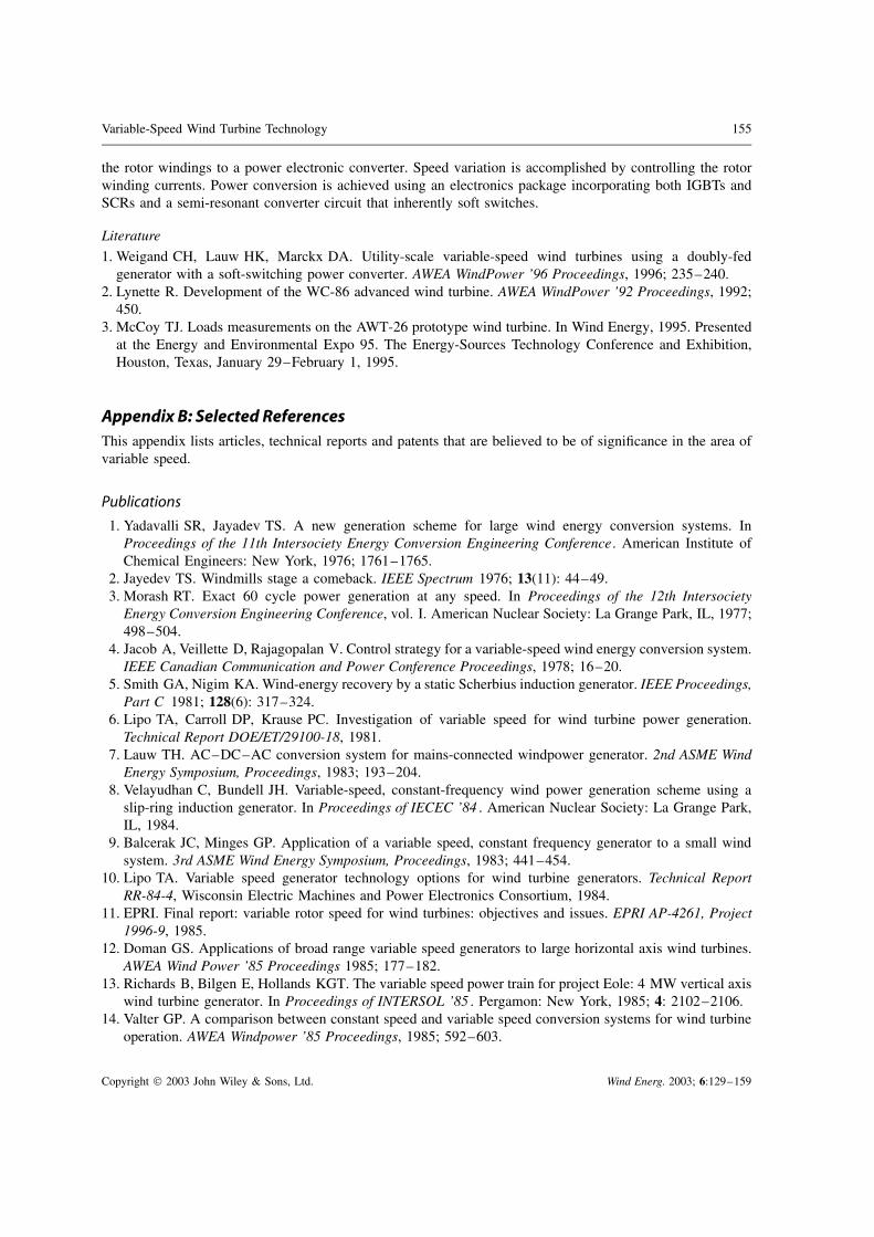
Variable-Speed Wind Turbine Technology 155
the rotor windings to a power electronic converter. Speed variation is accomplished by controlling the rotorwinding currents. Power conversion is achieved using an electronics package incorporating both IGBTs andSCRs and a semi-resonant converter circuit that inherently soft switches.
Literature1. Weigand CH, Lauw HK, Marckx DA. Utility-scale variable-speed wind turbines using a doubly-fed
generator with a soft-switching power converter. AWEA WindPower ’96 Proceedings, 1996; 235–240.2. Lynette R. Development of the WC-86 advanced wind turbine. AWEA WindPower ’92 Proceedings, 1992;
450.3. McCoy TJ. Loads measurements on the AWT-26 prototype wind turbine. In Wind Energy, 1995. Presented
at the Energy and Environmental Expo 95. The Energy-Sources Technology Conference and Exhibition,Houston, Texas, January 29–February 1, 1995.
Appendix B: Selected ReferencesThis appendix lists articles, technical reports and patents that are believed to be of significance in the area ofvariable speed.
Publications
1. Yadavalli SR, Jayadev TS. A new generation scheme for large wind energy conversion systems. InProceedings of the 11th Intersociety Energy Conversion Engineering Conference. American Institute ofChemical Engineers: New York, 1976; 1761–1765.
2. Jayedev TS. Windmills stage a comeback. IEEE Spectrum 1976; 13(11): 44–49.3. Morash RT. Exact 60 cycle power generation at any speed. In Proceedings of the 12th Intersociety
Energy Conversion Engineering Conference, vol. I. American Nuclear Society: La Grange Park, IL, 1977;498–504.
4. Jacob A, Veillette D, Rajagopalan V. Control strategy for a variable-speed wind energy conversion system.IEEE Canadian Communication and Power Conference Proceedings, 1978; 16–20.
5. Smith GA, Nigim KA. Wind-energy recovery by a static Scherbius induction generator. IEEE Proceedings,Part C 1981; 128(6): 317–324.
6. Lipo TA, Carroll DP, Krause PC. Investigation of variable speed for wind turbine power generation.Technical Report DOE/ET/29100-18, 1981.
7. Lauw TH. AC–DC–AC conversion system for mains-connected windpower generator. 2nd ASME WindEnergy Symposium, Proceedings, 1983; 193–204.
8. Velayudhan C, Bundell JH. Variable-speed, constant-frequency wind power generation scheme using aslip-ring induction generator. In Proceedings of IECEC ’84 . American Nuclear Society: La Grange Park,IL, 1984.
9. Balcerak JC, Minges GP. Application of a variable speed, constant frequency generator to a small windsystem. 3rd ASME Wind Energy Symposium, Proceedings, 1983; 441–454.
10. Lipo TA. Variable speed generator technology options for wind turbine generators. Technical ReportRR-84-4, Wisconsin Electric Machines and Power Electronics Consortium, 1984.
11. EPRI. Final report: variable rotor speed for wind turbines: objectives and issues. EPRI AP-4261, Project1996-9, 1985.
12. Doman GS. Applications of broad range variable speed generators to large horizontal axis wind turbines.AWEA Wind Power ’85 Proceedings 1985; 177–182.
13. Richards B, Bilgen E, Hollands KGT. The variable speed power train for project Eole: 4 MW vertical axiswind turbine generator. In Proceedings of INTERSOL ’85 . Pergamon: New York, 1985; 4: 2102–2106.
14. Valter GP. A comparison between constant speed and variable speed conversion systems for wind turbineoperation. AWEA Windpower ’85 Proceedings, 1985; 592–603.
Copyright " 2003 John Wiley & Sons, Ltd. Wind Energ. 2003; 6:129–159

156 P. W. Carlin, A. S. Laxson and E. B. Muljadi
15. Schmidt WC, Birchenough AG. Evaluating variable speed generating systems on the DOE/NASA MOD-0wind turbine. AWEA Windpower ’85 Proceedings, 1985; 171–176.
16. Ernst J, Palz W. Control of a variable speed wind energy converter with a synchronous and a d.c. linkconverter. In Proceedings of EWEC ’84 . H. S. Stephens and Associates: Bedford, 1985; 606–611.
17. Boldin D, Muehloecker H, Palz W. Induction generators adapted to variable speed operated wind turbines.Proceedings of EWEC ’84 . H. S. Stephens and Associates: Bedford, 1985; 542–547.
18. Herrera JI, Reddoch TW, Lawler JS. Experimental investigation of a variable speed constant frequencyelectric generating system from a utility perspective. Technical Report DOE/NASA-4105-1, NASA-CR-174950, 1985.
19. Naganathan S, Sharaf AM. Microprocessor control of wind driven squirrel cage induction generator. InProceedings of Power Electronics & Applications . Koninklijke Vlaamse Ingenieursvereniging, Technolo-gisch Inst. Antwerp, 1985; 2.7–2.12.
20. DiValentin E. The application of broad range variable speed for wind turbine enhancements. EWEC ’86Proceedings, 1986; 669–674.
21. Steinbuch M, Meiring F. Analysis and simulation of a wind turbine with variable speed. Report PB-87-163150/XAB. Kema Scientific and Technical Reports 1986; 4(7): 71–78.
22. Almarsoomi AR. Laboratory investigation of wind power generation using variable speed synchronousgenerators. Report STEV-VIND-86-17, Statens Energiverk, Stockholm, 1986; 60.
23. Carlson O, Hylander J, Tsiolis S. Variable speed AC-generators applied in WECS. European Wind EnergyAssociation Conference & Exposition Proceedings 7–9 Nov. 1986; 1: 685–690.
24. Hughes PS. Variable-speed generator improves turbine efficiency. Modern Power Systems 1986; 6(12):32–33,35.
25. Doman G, Swift AHP. Influence of broad range variable speed operation upon the Hamilton standardWTS-4 wind turbine. 5th ASME Wind Energy Symposium Proceedings, 1986; 127.
26. Quareshi S, Richards B. Design features of project Eole prototype. Third annual conference of CANWEA’87 Proceedings, 1988; 41–45.
27. Carlson O, Tsiolis S, Johansson G. Variable speed AC-drive system with pitch or yaw control. AWEAWindpower ’87 Proceedings, 1987; 60–65.
28. Smith GA. Variable speed induction generators. ETSU-N-103, Proceedings of the British Wind EnergyAssociation DEN Workshop on Electrical Generation Aspects of Wind Turbine Operation, May 12, 1987.
29. Steinbuch M. Optimal multivariable control of a wind turbine with variable speed. Wind Engineering1987; 11(3): 153–163.
30. Herrera JI, Reddoch TW. Analysis of the electrical characteristics of a Westinghouse variable speedgenerating system for wind turbine applications. SERI Technical Report STR-217-3133, 1988.
31. Weh H, Hoffman H, Landrath J, Mosebach H, Poschadel J. Directly-driven permanent-magnet excitedsynchronous generator for variable speed operation. In Proceedings of EWEC ’88 . H.S. Stephens andAssociates: Bedford, 1988; 566–572.
32. Carlin PW, Swift AHP, Thresher RW. Analysis of variable speed operation of horizontal axis windturbines. 7th ASME Wind Energy Symposium Proceedings, 1988; 195.
33. Power-electronic, variable-speed wind turbine development: 1988–1993. A summary of the 33 m-VS windturbine development program conducted by KENETECH Windpower, Pacific Gas and Electric Company,Niagara Mohawk Power Corporation, and EPRI. EPRI Technical Report TR-104738, Projects 1590-16;3062-02, 1995.
34. Carlin PW. The probable source of certain spurious frequencies found in the output of a variable speedgenerating system using slip recovery. SERI Technical Paper TP-217-3515, 1989.
35. Carlson O, Hylander J. Variable speed AC-generators in wind energy converters. IEEE MELECON ’89:5th Mediterranean Electrotechnical Conference Proceedings, 1989; 91–94.
36. Matsuzaka T, Tsuchiya K, Yamada S, Kitahara H. A variable speed wind generating system and its testresults. In Proceedings of EWEC ’89 , pt. 2. Peter Peregrinus: London, 1989; 608–612.
Copyright " 2003 John Wiley & Sons, Ltd. Wind Energ. 2003; 6:129–159
Variable-Speed Wind Turbine Technology 157
37. Vachon W. Smart control algorithms for operation of variable speed wind turbines. 9th ASME Wind EnergySymposium Proceedings, 1990; 191–199.
38. McNerney G, Richardson RD, Holley W. The effect of a power electronic converter on power fluctuationand harmonic distortion in a WECS. 9th ASME Wind Energy Symposium Proceedings, 1990; 237–241.
39. Avolio S, Calo C, Foli U, Rubbi L, Casale C, Sesto E. Gamma 60 1"5 MW wind turbine generator. InProceedings of EWEC ’90 . H. S. Stephens and Associates: Bedford, 1990; 472–477.
40. Djurovic M, Savelic R. Double fed induction generator for variable speed constant frequency. In Pro-ceedings of World Renewable Energy Congress v3, Pergamon: Oxford, 1990; 1613–1619.
41. Lauw HK, Krishnan S. Control aspects of the brushless doubly-fed machine. Technical Report DOE/BP/24332-1, Bonneville Power Administration, 1990.
42. Vas P. Vector control of AC machines. In Monographs in Electrical and Electronic Engineering, vol. 22.Clarendonsol Oxford University Press: Oxford, 1990.
43. Implementing Agreement for a Programme of Research and Development on Wind Energy ConversionSystems—Annex XI; 21st Meeting of Experts, Electrical Systems for Wind Turbines with Constant andVariable Speed. IEA: 1991.
44. Vachon WA. Control of variable speed wind turbines. 10th ASME Wind Energy Symposium Proceedings,1991; 73–82.
45. Weber TL, Wilson RE, Walker SN. Analysis of a teetered variable speed rotor. SERI Technical PaperTP-257-4366, 1991.
46. Ghandakly AA, Sbeiti ZH. A digital optimal controller for VSCF wind generators. IEEE IndustryApplication Society Annual Meeting Proceedings, 1991; 1618–1623.
47. Pierek JTG, Van Engelen TG, Baltus CWA, Veltman AT, Warmenhoven A, Hoeijmakers MJ, Vleeshouw-ers JM. A variable speed system with integral control for wind turbines (IRFLET): design of the test-rig.ECN-RX-91-040, Netherlands Energy Research Foundation (ECN), Petten, 1991.
48. Schluter LL, Vachon WA. Advanced control strategies for wind turbines. AWEA WindPower ’92 Proceed-ings, 1992; 267–275.
49. Veltman AT, De Haan SWH, Frumea CFA, Wildenbeest E, Smith GA, Infield DG, Simmons DA. Advan-ced power interface and controller for variable speed wind turbines. Technical Report ECN-RX-93-040,Netherlands Energy Research Foundation (ECN), Petten, 1993.
50. Vachon WA. Control algorithms for effective operation of variable-speed wind turbines. Technical ReportSAND-90-7112, Sandia National Laboratories, 1993.
51. Yonah ZO, El-Serafi AM, Krause AE. Regulation of terminal voltage and output frequency of a variable-speed dual-excited synchronous generator by using a computer-based two-phase excitation system.Canadian Conference on Electrical and Computer Engineering Proceedings, 1993.
52. Torrey DA, Childs SE. Development of variable-reluctance wind generators. AWEA WindPower ’93Proceedings, 1993; 258–265.
53. Hagg F, Joosse PA, Kuik GAM, van Beurskens JHM, Dekker JWM. The results of the Dutch Flexhatprogramme: the technology for the next generation of wind turbines. AWEA WindPower’93 Proceedings,1993; 331–341.
54. Smith GA, Stephens RG, Marshall P, Kansara M. Sinewave interface for variable-speed wind turbines.In Proceedings of the 5th European Conference on Power Electronics and Applications . IEE: Stevenage,1993; 97–102.
55. Pierek JTG, Frumau CFA, Veltman AT, Wildenbeest EJ, De Haan SWH. Advanced AC–DC–AC con-verter for variable speed wind turbines. Technical Report ECN-C-94-017, Netherlands Energy ResearchFoundation (ECN), Petten, 1994.
56. Ekelund T. Control of variable speed wind turbines in a broad range of wind speeds. Technical ReportNUTEK-VIND-94-9, Swedish National Board for Industrial and Technical Development (NUTEK),Stockholm, 1994.
57. Weigand C, Marckx DA. Variable speed wind generation: electrical options and power systems issues.AWEA WindPower ’94 Proceedings, 1994.
Copyright " 2003 John Wiley & Sons, Ltd. Wind Energ. 2003; 6:129–159
158 P. W. Carlin, A. S. Laxson and E. B. Muljadi
58. Spera DA (Ed.). Wind Turbine Technology; Fundamental Concepts of Wind Turbine Engineering . ASMEPress: New York, 1994.
59. Spee R, Bhowmik S, Enslin JH. Novel control strategies for variable-speed doubly fed wind powergeneration systems. Renewable Energy 1995; 6(8): 907–915.
60. Munz H, Connor B, Leithead WE. Sensitivity of performance of stall regulated variable speed HAWTsto rotor inertia. In Proceedings of the British Wind Energy Association Conference on Wind EnergyConversion . Mechanical Engineering Publications: London; 1995, 261–266.
61. Chen Z, Spooner E. Modular, permanent-magnet generator for variable speed wind turbines. In Proceed-ings of the 7th International Conference on Electrical Machines and Drives. IEEE Conference PublicationNo. 412 . IEEE: Stevenage, 1995; 453–457.
62. Jones R, Gilmore I. Benefits of sinusoidal rectifiers on variable speed wind turbines—high qualitymains power from variable speed wind turbines. In Proceedings of the British Wind Energy Associ-ation Conference on Wind Energy Conversion . Mechanical Engineering Publications: London, 1995;339–345.
63. Muljadi E, Butterfield CP, Migliore P. Variable speed operating of generators with rotor speed feedbackin wind power applications. ASME Wind Energy Proceedings, 1996; 120–130.
64. EPRID Final report: direct-drive wind turbine feasibility study. EPRI TR-106794, Project 1590-07, 1996.65. Muljadi E, Gregory B, Broad D. Self-excited induction generator for variable-speed wind turbine gener-
ation. Technical Report NREL/CP-440-21436, 1996.66. Weigand CH, Lauw HK, Marckx DA. Utility-scale variable-speed wind turbines using a doubly-fed
generator with a soft-switching power converter. AWEA Windpower ’96 Proceedings, 1996; 235–240.67. Smith GA. A novel converter for VSCF wind turbines. Renewable Energy 1996; 9: 1–4.68. Pena R, Clare JC, Asher GM. A doubly fed induction generator using back-to-back PWM converters
supplying an isolated load from a variable speed wind turbine. IEE Proceedings, Electric PowerApplications Stevenage, England, 1996, 143(5): 380–387.
69. Lior D, Idan M. A novel variable speed wind turbine transmission and control. In Proceedings of the 36thIsrael-Annual Conference on Aerospace Sciences . AIAA: New York, 1996.
70. Carlson O, Ulen E. Torque control of synchronous and induction generators for variable speed operationof wind turbines. In Proceedings of EWEC’96 . H. S. Stephens and Associates: Bedford, 1996; 406–409.
71. Carlson O, Hylander J, Thorborg K. Survey of variable speed operation of wind turbines. In Proceedingsof EWEC ’96 . H. S. Stephens and Associates: Bedford, 1996.
72. Zinger DS, Muljadi E, Miller A. Simple control scheme for variable speed wind turbines. 31st IEEEIndustry Applications Meeting Proceedings, 1996; 3: 1613–1618.
73. Lampola P, Perho J. Electromagnetic analysis of a low-speed permanent-magnet wind generator. InProceedings of the International Conference on Opportunities and Advances in International ElectricPower Generation. IEEE Conference Publication No. 419 . IEE: Stevenage, 1996; 55–58.
74. Kendall L, Balas MJ, Yung JL, Fingersh LJ. Application of proportional—Integral and disturbanceaccommodating control to variable speed variable pitch horizontal axis wind turbines. Wind Engineering1997; 21(1): 21–38.
75. Simoes MG, Bose BK, Spiegel RJ. Design and performance evaluation of a fuzzy-logic-based variablespeed wind generation system. IEEE Transactions on Industry Applications 1997; 33(4): 956–965.
76. Atkinson DJ, Lakin RA, Jones R. Vector-controlled doubly-fed induction generator for a variable-speedwind turbine application. Transactions of the Institute of Measurement and Control 1997; 19(1): 2–12.
77. Hand MM, Balas MJ. Systematic approach for PID controller design for pitch-regulated, variable-speedwind turbines. 17th ASME Wind Energy Symposium Proceedings, 1997; 89–94.
78. Sutherland HJ, Carlin PW. Damage measurements on the NWTC direct-drive, variable-speed test bed.17th ASME Wind Energy Symposium Proceedings, 1998; 315–322.
79. Fingersh LJ, Carlin PW. Results from the NREL variable-speed test bed. 17th ASME Wind EnergySymposium Proceedings, 1998; 233–237.
Copyright " 2003 John Wiley & Sons, Ltd. Wind Energ. 2003; 6:129–159

Variable-Speed Wind Turbine Technology 159
80. Muljadi E, Pierce K, Migliore P. Control strategy for variable-speed, stall-regulated wind turbines.Technical Report NREL/CP-500-24311, 1998.
Patents1. Soderholm LH, Andrew JF. Field control for wind driven generators. US Patent 4331881, 1982.2. Barron B, Rao SC. Methods and apparatus for maximizing and stabilizing electric power derived from
wind driven sources. US Patent 4400659, 1983.3. Wertheim MM, Herbermann RJ. Wind turbine maximum power tracking device. US Patent 4525633,
1985.4. Baskin JM, Miller GE, Wiesner W. Wind powered system for generating electricity. US Patent 4565929,
1986.5. Longrigg P. Wind energy conversion system. US Patent 4651017, 1987.6. Doman GS, Kos JM, Harner KI, DiValentin ED, Healy HS. Variable speed wind turbine. US Patent
4695736, 1987.7. Kos JM, Rapp AF. Speed avoidance logic for a variable speed wind turbine. US Patent 4700081, 1987.8. DiValentin ED, Healy HS. Torque control for a variable speed wind turbine. US Patent 4703189, 1987.9. Lauw HK, Alexander GC. Doubly fed generator variable speed generation control system. US Patent
4994684, 1991.10. Richardson RD, Erdman WL. Variable speed wind turbine. US Patent 5083039, 1992.11. Holley WE. Speed control system for a variable speed wind turbine. US Patent 5155375, 1992.12. Erdman WL. Variable speed wind turbine with reduced power fluctuation and a static VAR mode of
operation. US Patent 5225712, 1993.13. Holley WE. Speed control system for a variable speed wind turbine. US Patent 5289041, 1994.14. Muljadi EB. Variable speed wind turbine generator with zero-sequence filter. US Patent 5798632, 1998.
Copyright " 2003 John Wiley & Sons, Ltd. Wind Energ. 2003; 6:129–159