WEST ZONE POWER DISTRIBUTION CO. LTD. (WZPDCL) Tender ...
449
WEST ZONE POWER DISTRIBUTION CO. LTD. (WZPDCL) Tender Document For Supply & Installation of Plant & Equipment (International) One Stage two Envelope Tendering for Turnkey Contract FOR DESIGN, SUPPLY, INSTALLATION, TESTING AND COMMISSIONING OF 33/11KV, 2X10/13.33 MVA (REGULAR TYPE, AIS) 03 NOS NEW SUBSTATION ON TURNKEY BASIS AT NABOGRAM, S&D-1, BARISAL, 22 ROSHI, SADARPUR ESU, FARIDPUR AND CHARERHAT, S&D-3, KHULNA. UNDER EXPANSION AND UP-GRADATION OF POWER DISTRIBUTION SYSTEM PROJECT (EAUPDSP) Invitation for Tender No.: 27.22.4785.800.50.003.21.66 Issued on: 15.03.2021 Tender Package No.: GD16 (FY-2020-21) PROJECT DIRECTOR EXPANSION AND UP-GRADATION OF POWER DISTRIBUTION SYSTEM PROJECT (EAUPDSP), WZPDCL, KHULNA March 2021 Volume-2 of 2 This document may be customized/ edited as per scope of tenderer for tender submission purpose, if it's required but this document is not a guaranteed or signed copy. The authority is not liable for any customization or editable error of this document. If you want a guaranteed or signed copy of this document then buy a hard copy from mentioned place in tender notice.
Transcript of WEST ZONE POWER DISTRIBUTION CO. LTD. (WZPDCL) Tender ...

WEST ZONE POWER DISTRIBUTION CO. LTD. (WZPDCL)
Tender Document
For Supply & Installation of Plant & Equipment (International)
One Stage two Envelope Tendering for Turnkey Contract
FOR
DESIGN, SUPPLY, INSTALLATION, TESTING AND COMMISSIONING OF 33/11KV,
2X10/13.33 MVA (REGULAR TYPE, AIS) 03 NOS NEW SUBSTATION ON TURNKEY BASIS AT
NABOGRAM, S&D-1, BARISAL, 22 ROSHI, SADARPUR ESU, FARIDPUR AND CHARERHAT,
S&D-3, KHULNA.
UNDER
EXPANSION AND UP-GRADATION OF POWER DISTRIBUTION SYSTEM PROJECT
(EAUPDSP)
Invitation for Tender No.: 27.22.4785.800.50.003.21.66
Issued on: 15.03.2021
Tender Package No.: GD16 (FY-2020-21)
PROJECT DIRECTOR
EXPANSION AND UP-GRADATION OF POWER DISTRIBUTION SYSTEM
PROJECT (EAUPDSP), WZPDCL, KHULNA
March 2021
Volume-2 of 2
This document may be
customized/ edited as per
scope of tenderer for tender
submission purpose, if it's
required but this document is
not a guaranteed or signed
copy. The authority is not
liable for any customization or
editable error of this
document. If you want a
guaranteed or signed copy of
this document then buy a hard
copy from mentioned place in
tender notice.

Table of Contents
Volume-1 of 2
Section-1: Instruction to Tenderers (ITT)
Section-2: Tender Data Sheet (TDS)
Section-3: General Conditions of Contract (GCC)
Section-4: Particular Conditions of Contract (PCC)
Section-5: Tender & Contract Forms
Section-6: Employer’s Requirement
Volume-2 of 2
Section-7: Technical Specifications
Section-7.1: Technical Specification for AIS (Regular type) substation
equipment
Section-7.2: Technical Specification for Power Transformer & Station
Transformer
Section-7.3: Technical Specification of Power Cables & Conductor
Section-7.4: Technical Specification for Substation Automation System
Section-7.5: Civil and Architecture General Provision
Section-7.6: Technical Specification for CCTV System
Section-7.7: Supplementary Information
Section-7.8: Inspection and Testing of Equipment
Section-7.9: Pre-Commissioning Test of Substation
Section-8: Guaranteed Technical Particulars (GTP)
Section-9: Drawings

SECTION 7: TECHNICAL SPECIFICATIONS

7.1 TECHNICAL SPECIFICATIONS FOR 33/11 KV AIS SUBSTATION
EQUIPMENT

Table of Contents
7.1 TECHNICAL SPECIFICATIONS FOR 33/11 KV AIS SUBSTATION EQUIPMENT ........... 262
7.1.1 Scope ........................................................................................................................... 262
7.1.2 References .................................................................................................................. 262
7.1.3 33 kV Vacuum Circuit Breaker ...................................................................................... 263
7.1.4. 33kV PCM .................................................................................................................... 265
7.1.4.1. A. 33 kV Control, Signaling Metering and Relay Panel for Power Transformer, each
comprising: 265
7.1.4.1. B. 33 KV CONTROL, SIGNALING METERING AND RELAY PANEL FOR INCOMING
/OUTGOING FEEDER .................................................................................................................. 266
7.1.4. C FOR 33 KV PANEL FEATURES: .................................................................................. 267
7.1.4.1. D Alarms ..................................................................................................................... 269
7.1.4.1. E TESTS ....................................................................................................................... 270
7.1.4.1. F. Construction Details ................................................................................................ 270
7.1.4.1. G. PANEL WIRING .................................................................................................... 271
7.1.4.1. H. POWER SUPPLY DISCONNECT ................................................................................. 273
7.1.4.1. I INDICATING LIGHTS ................................................................................................. 273
7.1.4.1. J TERMINAL BLOCKS .................................................................................................. 273
7.1.4.1. K INSTRUMENTS AND DEVICES .................................................................................. 274
7.1.4.1. L PANEL LIGHTING ..................................................................................................... 274
7.1.4.1. M CONTROL AND SELECTOR SWITCHES ............................................................... 274
7.1.4.1. N ANNUNCIATOR .................................................................................................. 274
7.1.4.1. O INDICATING AMMETERS .................................................................................... 275
7.1.4.1. P EARTHING SYSTEM ............................................................................................. 275
7.1.4.1. Q DISTRIBUTION AND CONTROL OF AUX. POWER CIRCUIT .................................. 276
7.1.4.1. R TRIP RELAYS ............................................................................................................. 277
7.1.4.1. S SUPERVISION RELAYS .............................................................................................. 277
7.1.4.1.T MIMIC BUS .............................................................................................................. 277
7.1.4.1.U Auxiliary Relay ......................................................................................................... 278
7.1.4.1.V Annunciator............................................................................................................. 278
7.1.4.1.W AVR Relay ................................................................................................................ 278
7.1.4.1.X Name plate & Ratings: ............................................................................................ 278
7.1.4.1.Y PAINTING ................................................................................................................. 279

7.1.4.1. Z SPECIFICATION OF 110V, 3 x 5(6) A, 3-PHASE, 4-WIRE, 3-ELEMENT, INDOOR
TYPE MULTI-TARIFF PROGRAMMABLE METER WITH ASSOCIATED INSTRUMENT
TRANSFORMERS ENCLOSED IN METERING PANEL. .................................................................... 279
7.1.5 TECHNICAL SPECIFICATIONS 11KV VACUUM CIRCUIT BREAKERS WITH PROTECTION,
CONTROL & METERING CUBICLES. ............................................................................................. 287
7.1.5.1 GENERAL ..................................................................................................................... 287
7.1.5.1.2 11KV TRANSFORMER INCOMING CUBICLES, EACH PANEL COMPRISING: ..................................... 288
7.1.5.1.3 Bus Coupler with bus riser Cubicles each comprising:................................................. 290
7.1.5.1.4 Out-going Cubicles, Each Comprising: ......................................................................... 292
7.1.5.1.5 MEASURING CUBICLES, EACH COMPRISING: .......................................................................... 294
7.1.5.6 FEATURES & ACCESSORIES .......................................................................................... 294
7.1.5.7. PROTECTIVE RELAYS ....................................................................................................... 296
7.1.5.8. ENERGY METERS: ................................................................................................... 296
7.1.5.9. CONSTRUCTION DETAILS ............................................................................................... 297
7.1.5.10 PANEL WIRING: ....................................................................................................... 297
7.1.5.11 INDICATING LIGHTS ................................................................................................. 298
7.1.5.12 POWER SUPPLY DISCONNECT ................................................................................. 298
7.1.5.13 TERMINAL BLOCKS .................................................................................................. 298
7.1.5.14 INSTRUMENTS AND DEVICES .................................................................................. 298
7.1.5.24 TRIP RELAYS ....................................................................................................... 300
7.1.5.25 SUPERVISION RELAYS ............................................................................................. 300
7.1.5.26 MIMIC BUS ............................................................................................................ 300
7.1.5.27 AUXILIARY RELAYS ................................................................................................... 301
7.1.5.28 LIVE LINE INDICATOR .............................................................................................. 301
7.1.6 Technical Specification of 33KV Isolator (1250A) with Earth blade ............................ 303
7.1.7 Technical Specification of 33KV Isolator (1250A) without Earth blade ...................... 305
7.1.8 Technical Specification of 33 kV Off-Load Fused Isolator for auxiliary transformer. . 307
7.1.9 Technical Specification of 33 kV Off-Load Isolator without Earth Blade for Bus Section
308
7.1.10 Technical Specification of 33 kV Off-Load Isolator With Earth Blade ........................ 310
7.1.11 33KV Current Transformer .......................................................................................... 311
7.1.12 11KV Current Transformer .......................................................................................... 312
7.1.13 Technical Specification of single phase 33KV Potential Transformer ......................... 313
7.1.14 Technical Specification of 11KV Potential Transformer .............................................. 314
7.1.15 Technical Specification of 33 kV Single Phase Lightning Arrester .............................. 315

7.1.16 Technical Specification of Substation Battery and Battery Charger .......................... 317
7.1.17 Battery Charger ........................................................................................................... 319
7.1.18 Grounding Material ..................................................................................................... 323
7.1.19 Technical Specifications 33kV Disc Insulator with Fittings ........................................... 323
7.1.20 H- Type Connectors................................................................................................. 325
7.1.21 Shield Wires: ................................................................................................................ 326
7.1.22 PG Clamp: ................................................................................................................. 326
7.1.23 LV AC Distribution Panel with interlocking facilities. ................................................... 327
7.1.24 DC Distribution Panel with interlocking facilities. ........................................................ 328
7.1.25 Sub-Station Steel Structure ......................................................................................... 329
7.1.26 Bus-Bar Conductor and Jumpers ................................................................................. 333
7.1.27 Electrical Hardware for 33kV Switchyard .................................................................... 334
7.1.28 Shield Wires ................................................................................................................. 334
7.1.29 Sub-Station Earthing ................................................................................................... 335

Tender Doc for 33/11 KV SS (AIS), Pkg. GD16 (Vol 2 of 2) 262 EAUPDSP, WZPDCL
7.1 TECHNICAL SPECIFICATIONS FOR 33/11 KV AIS SUBSTATION EQUIPMENT
7.1.1 Scope
This clause describes the General Technical Requirements for the new 33 KV VCB with PCM
and 11KV AIS Switchgear and general switchyard equipment, and shall be read in
conjunction with the Project Requirements, Schedules and Drawings in the specification.
The Contractor shall demonstrate that the switchgear has been designed, built and
installed in accordance with the relevant international standards and the specification as
specified in the tender documents. It shall also operate and perform on a site in accordance
with the requirements of the specification and in the environment defined herein.
The design shall be proven by the submission at the time of Tender of test certificates
covering all specified tests deemed to be pertinent to the plant and to the conditions in
which it will operate or, if such test certificates cannot be supplied or are deemed
unacceptable by the Engineer, type tests which will be subject to the conditions of this
Contract shall be carried out at no extra cost to the Employer.
The requirement for switchgear spares, tools and appliances, including test, maintenance
and handling equipment shall be as stated in the tender document.
7.1.2 References
7.1.2.1 British Standards
BS 159 Specifications for HV bus bars and bus bar connections
BS 1977 Specifications for high conductivity copper tubes for electrical
BS
BS
2898
3938
Specifications for wrought aluminum for electrical purposes.
Strip with Drawn or rolled edges.
BS 5253 Specifications for AC disconnectors and earthing switches.
BS 6651 Lightning Protection
BS 7354 Code of practice for design of HV open terminal stations.
7.1.2.2 IEC Standards
1. IEC 62271 HV Switchgear and Control gear.
2. IEC 60376 Specification and acceptance of new Sulphur hexafluoride
3. IEC 60480 Guide to checking of Sulphur hexafluoride taken from electrical equipment.
4. IEC 60060 High Voltage test techniques.
5. IEC 60071 Insulation Co-ordination
6. IEC 60099-5 Surge arresters Part 5: Selection and application recommendation
7. IEC 60129 AC disconnectors (isolators) and earthing switches
8. IEC 60044-1 Current transformers.
9. IEC 60044-2 Voltage transformers.
10. IEC 60273 Characteristics of indoor and outdoor post insulators for systems with nominal voltages greater than 1000V.
11. IEC 61850 Communication network and system in substation
12. IEC 60529 Degrees of protection provided by Enclosure (IP code)

Tender Doc for 33/11 KV SS (AIS), Pkg. GD16 (Vol 2 of 2) 263 EAUPDSP, WZPDCL
13. IEC 60255 Electrical relays
14. IEC 62271-1 High voltage switchgear and control gear: common specification
15. IEC 62271-100 High voltage switchgear and control gear: Part 100: Alternating current circuit breakers
16. IEC 62271-102 High voltage switchgear and control gear: Part 102: Alternating current disconnector and earthing switch
17 IEC 61850 Communication Protocol
7.1.3 33 kV Vacuum Circuit Breaker
7.1.3.1 General Features:
1. Installation : Outdoor Sub-station.
2. Type : Vacuum Circuit Breakers
3. Number of Phase : 3 (Three)
4. Operation : Single Break in Service/ Pole
5. Service Voltage : 33 KV
6. Maximum Rate Voltage : 36 KV
7. Frequency : 50 Hz
8. Normal Rated Current for : 1250 A
9. Symmetrical Breaking Capacity : 1500 MVA
10. Asymmetry : 50%
11. Short Time Current Duration : 25 KA, 3 Sec.
12. Making Current (Peak) KA : 62.5KA
13. Opening Time (Maximum) : 0.05 Sec.
14. Breaking Time : 2/3 Cycle
15. Capacity of Vacuum Interrupter at
rated short circuit current switching
: ≥ 100 nos. of operations
16. Basic Insulation Level (1.2/50
Micro Second Wave)
: 170 KV
17. Power Frequency Test Voltage (Dry) 70 KV at 50 Hz, 1 Min.
18. Rated Operating Sequence : 0-0.3 Sec – CO – 3 min – CO
19. Standard : Design, Manufacture, Testing, Installation
and Performance shall be in accordance
with the latest edition of applicable IEC–
6056 & IEC-62271-100
20. FEATURES
- Circuit Breaker terminal connectors shall be suitable for ACSR Martin, Merlin, and Grosbeak (636MCM).
- Grading terminal connector.
- All current carrying parts shall be made of copper e x c e p t Top & Bottom pad of connector, which shall be Bi-metallic/Al-Alloy.
- Externally visible circuit breaker position indicator.

Tender Doc for 33/11 KV SS (AIS), Pkg. GD16 (Vol 2 of 2) 264 EAUPDSP, WZPDCL
- Electrically remote-controlled operating mechanism.
- Shall be capable of the interrupting duties produced by the switching of transformer magnetizing current and the switching of line charging current. Tests certificate demonstrating this ability of the circuit breakers shall be submitted with the offer.
- Circuit Breaker closing mechanism shall be 230- v o l t AC motor wound spring- operated type such that the closing speed is independent of the operator.
- Shall be two tripping coils and one closing coil.
- Hand closing and tripping shall be done through manual levers.
- Trip free mechanism as specified in IEC 60056-1 i.e. tripping is independent.
- Local “Close” and “Trip” controller.
- VCB should be re-strike free.
- VCB should be trip free.
- Operation Counter.
- Supporting Steel Structure.
- Bushing Insulator as Specified in IEC-60137.
- Weather proof sheet steel control kiosk, with hinged door on three sides and necessary multi-core cable glands. Controls from this position will normally is used under maintenance and emergency conditions only. AC 230V lighting system inside the door of control kiosk shall be provided.
- ARC suppression type contacts.
- Manually operating devices for slow closing for inspection and maintenance. It shall not be possible to slow close a breaker when in normal services.
- Earthing pad with provision for earth leads.
- Standard sundries like anti-condensation heaters, MCBS wiring board etc. Facilities to be incorporate for tripping and lockout of the breaker in the event Vacuum failure falling below stipulated value.
- Rating p la t e and d i ag r a m p l a t e s h a l l b e m ade o f s ta i nles s s t e e l a n d have engraved letters filled with black enamel paint.
- Evidence of prototype tests together with test certificate from a recognized institution covering the equipment shall be furnished with the offer. The test duty shall be as per the requirements of IEC–60056.
- Laminated control & protection drawing set shall be fitted/supplied inside the control box/kiosk.
- Motor-driven, spring charged
- Automatically charged after each closing operation
- O-C-O operation without recharging
- Mechanical / electrical anti-pumping
- Provision for manual charging
- Manual closing and tripping arrangement
- Mechanical ON-OFF, operation counter and spring-charged indication
- All necessary positive interlocks installed, as per IEC guidelines.

Tender Doc for 33/11 KV SS (AIS), Pkg. GD16 (Vol 2 of 2) 265 EAUPDSP, WZPDCL
7.1.3.2 TESTS AT MANUFACTURERS WORKS FOR OUTDOOR TYPE VCB
General
Functional electrical, material, mechanical and hydraulic tests shall be carried out at
manufacturers’ premises. The extent and method of recording the results shall be agreed by the
Purchaser in ample time to enable the tests to be satisfactorily witnessed or to make any
changes to the proposed program of tests.
Material Tests
The supplier shall provide test pieces free of charge as required to enable the quality of the
material to be determined at the supplier’s expense. Purchaser may at its own discretion and by
specific arrangement accept certified particulars of tests carried out in the absence of his
authorized representative.
Type Test
Type tests are required to prove the general design of the offered equipment’s/ materials. The
Tenderer shall submit the type test reports of the offered equipment’s/ materials from as per
relevant clause.
Routine Tests
All equipment’s/ materials shall be subjected to routine tests as per latest version of relevant
IEC/ BS or equivalent international standards as mentioned in the contract at the manufacturers
works and shall include, but not be limited to, an operational test.
7.1.4. 33kV PCM
7.1.4.1 General
The panels shall be vermin and dust proof free standing type completely metal enclosed by
sheet steel (minimum 1.62 mm thick) with necessary reinforcement color gray with appropriate
spray painting. The approximate size will be high 2350 mm, width 700 mm and front 900 mm,
suitable for opening at the back by hinged door with locking arrangement. The panels shall be
neatly and completely wired before shipment.
The work relating to protection, control and panels for 33/11KV Sub-stations shall comprise of
development of elementary diagram, design, manufacture, test and supply of pre-wired control
panels to be installed in the sub-station control room. The protection, control and panels are to
be pre-wired with relays and meters in position. The elementary primary diagram shall be
produced giving a clear representation of each protection, control and metering function. The
standard design, drawing, manufacturing, testing & performance shall be in accordance to the
IEC-298 standards.
7.1.4.1. A. 33 kV Control, Signaling Metering and Relay Panel for Power Transformer,
each comprising:
1. Indicating analogue/digital Ampere meter flush mounting with dual scales options, 0- 300/600A for Transformer connection to current transformer ratio 300-600/5-5- 5A
3 (three) nos.
2. Indicating analogue/ digital voltmeter with six position selector switch flush mounting with scales 0-40 KV for connection to potential transformer ratio (33/√3)/ (0.11/√3)/(0.11/√3) KV, (50 Hz).
1 (one) set

Tender Doc for 33/11 KV SS (AIS), Pkg. GD16 (Vol 2 of 2) 266 EAUPDSP, WZPDCL
3.
Numerical Programmable Multifunction KWh Meter of class of accuracy 0.2S with the features for measuring the parameters viz. phase voltages, phase currents, system frequency, per phase & total KW with demand, KVAR, Power factor etc. distinguishing import and export operation. Numerical Programmable Multifunction KWh Meter shall to have communication facilities supported by DLMS/COSEM, IEC 61107 and Modbus or IEC 61850.
1 (one) no.
4.
Numerical programmable type Three Phase combined directional IDMT Over Current relay and Earth fault protection relay of 5 Amps, 50 Hz, 110V dc, 3 second operating time ratings having 3 (Three) over current units and one earth fault with current setting range of the O/C & E/F relay shall be from 0.1*In to 30*In (where In is relay nominal current) for both overcurrent and earth fault element. All O/C & E/F relays shall have both IDMT & DT (51), Instantaneous (50), and 52BF function along with IEC NI, VI, EI, LTI etc. curve setting capability. This relay should have 16 BI, 11 BO (minimum) with rear FO-LC Port for IEC 61850 Communication and rear USB port for relay configuration, MIMIC display, CB control button (ON/OFF), and other specification as per tender clause: 7.4.6.3.
(Not to be included in Differential Relay). (Relay should have communication facilities as per IEC 61850).
1 (one) set
5.
Numerical programmable type Differential relay with REF inbuilt feature (Low impedance) for 33/11KV Power Transformer. This relay should have 7 BI, 7 BO (minimum) with rear FO-LC Port for IEC 61850 Communication and rear USB port for relay configuration, and other specification as per tender clause: 7.4.6.3. (Relay should have communication facilities as per IEC 61850).
1 (one) set
6 Separate Auxiliary Flag Relays for Device/Self Protection of Power Transformer to be provided. The following Auxiliary Flag Relays shall be available OTA, OTT, WTA, WTT, BA, BT, OLTC Surge, PRD for main tank, etc.
1 (one) set
7 OLTC Tap position indicator & Lower/Raise push-button switches with blinking feature along with AVR relay etc.
1 (one) set
8
All necessary switches (Local and remote selector switch, TNC switch, LAMP Check, ANN ACK, ANN reset, Push Button, etc. ), CT, PT test terminal blocks, signaling set lamps, master trip relay, trip circuit supervision relay for each trip circuit coil, PT supervision relay, auxiliary relay, MCB, fuse and provision for lighting etc. terminal blocks, mimic diagram with circuit breaker control indicating switches and isolating position indicating switches, indicating lamps shall be provided to indicate “Spring Charge”/ readiness for closing and healthy trip circuit indicating readiness for tripping. The mimic and positions of circuit breaker control cum position indicating switch and isolator position indicating switch arrangement in the panel. Mimic diagram shall contain LED based Semaphore Indicator for Isolator/Breaker/Earth switch position. The Annunciator shall have 24 windows and have built in buzzer and AC/DC fail relay. Multifunctional meter should have U, I, f, Pf, Ɵ, MW, MVAR etc. facilities.
1 (one) set
9 70 W, 230 V AC, Single Phase heater with thermostat and a visible light indicator which indicate the ''ON"- ''OFF" position of the heater
1 (one) set
7.1.4.1. B. 33 KV CONTROL, SIGNALING METERING AND RELAY PANEL FOR INCOMING
/OUTGOING FEEDER
1. Indicating analogue/ digital Ampere meter flush mounting with dual scales option (0-400A & 0-800A any one may use) for connecting to the current transformer (ratio 400- 800/5/5/5A)
3 (three)
nos.
2. Indicating analogue/ digital voltmeter with six position selectors switch flush
mounting with scales 0-40 KV for connection to potential transformer
1 (one)
set

Tender Doc for 33/11 KV SS (AIS), Pkg. GD16 (Vol 2 of 2) 267 EAUPDSP, WZPDCL
ratio (33/√3)/ (0.11/√3)/ (0.11/√3) KV, (50 Hz).
3. Numerical Programmable Multifunction bi-directional KWH energy meters with export and import energy measuring features of class of accuracy 0.2S with the features for measuring the parameters viz. phase voltages, phase currents, system frequency, per phase & total KW with demand, KVar, Power factor etc. distinguishing import and export operation. Numerical Programmable Multifunction KWh Meter shall to have communication facilities supported by DLMS/COSEM, IEC 61107 and Modbus or IEC 61850
1 (one)
no.
4. Numerical programmable type Three Phase combined IDMT Over Current relay and Earth fault protection relay of 5 Amps, 50 Hz, 110V dc, 3 second operating time ratings having 3 (Three) over current units and one earth fault with current setting range of the O/C & E/F relay shall be from 0.1*In to 30*In (where In is relay nominal current) for both overcurrent and earth fault element. All O/C & E/F relays shall have both IDMT & DT (51), Instantaneous (50), 52BF, and directional (67/67N) function along with IEC NI, VI, EI, LTI etc. curve setting capability. This relay should have 23 BI, 16 BO (minimum) with rear FO-LC Port for IEC 61850 Communication and rear USB port for relay configuration, MIMIC display, CB control button (ON/OFF), and other specification as per tender clause: 7.4.6.3.
(Relay should have communication facilities as per IEC 61850).
1 (one)
set
5. All necessary switches (Local and remote selector switch, TNC switch, LAMP Check, ANN ACK, ANN reset, Push Button, etc. ), CT, PT test terminal blocks, signaling set lamps, master trip relay, trip circuit supervision relay for each trip circuit coil, PT supervision relay, auxiliary relay, MCB, fuse and provision for lighting etc. terminal blocks, mimic diagram with circuit breaker control indicating switches and isolating position indicating switches, indicating lamps shall be provided to indicate “Spring Charge”/ readiness for closing and healthy trip circuit indicating readiness for tripping. The mimic and positions of circuit breaker control cum position indicating switch and isolator position indicating switch arrangement in the panel. Mimic diagram shall contain LED based Semaphore Indicator for Isolator/Breaker/Earth switch position. The Annunciator shall have 24 windows and have built in buzzer and AC/DC fail relay. Multifunctional meter should have U, I, f, Pf, Ɵ, MW, MVAR etc. facilities.
1 (one)
set
6. 70 W, 230 V AC, Single Phase heater with thermostat and a visible light indicator which indicate the ''ON"- ''OFF" position of the heater
1 (one)
set
7.1.4. C FOR 33 KV PANEL FEATURES:
Each PCM panel shall be equipped with the following:
a) (i) Instruments and Relays described elsewhere. All the relays shall be IEC 61850 protocol type for automation network of the 33/11kV Sub-station. In addition, numerical relay shall have sufficient contacts and shall be configured for SAS operation. Intermediate auxiliary relay with sufficient spare contacts shall be used for controlling CB or any other switching devices through numerical relay in case of SAS operation.
(ii) The numerical bay control IED’s shall be mounted together with all the relevant bay
protective relays in cubicles which is to be integrated with SAS.
b) Status indicating discrepancy, Control switches for 33 kV Circuit Breaker with safety arrangements.
c) Illuminated Circuit Breaker and Isolator position switches.
d) Signaling relays (annunciator, compact type) to yield audiovisual signals on faults and have reset feature.

Tender Doc for 33/11 KV SS (AIS), Pkg. GD16 (Vol 2 of 2) 268 EAUPDSP, WZPDCL
e) The inside of the panel will have all auxiliary relays to sense the operation of gas relays, over temperature, over current, differential relay operation failure of auxiliary voltage (DC & AC) etc. and to transmit for tripping and fault signaling.
f) All inside equipment described and required shall be neatly arranged inside the panel.
g) Thermostat control heater with status indicating illumination lamp (LED) shall be provided.
h) The terminal blocks for connecting the incoming multi-core cables shall be placed at the bottom part and necessary glands/ opening shall be provided for the entry of the outside cables.
i) Sufficient-working spaces shall be provided inside the panel between instruments and wiring for easy approach.
j) All AC, DC auxiliary power circuits and PT secondary circuits entering the control panel shall
be provided with MCCB. Separate MCBs shall be provided for DC supply to Power, Control
and Alarm & Indication circuits.
k) Provision to hang danger/ caution board.
l) The PCM panel shall be SCADA/SAS compatible and hence all intelligent devices, digital
energy meters etc. shall comply IEC61850. All physical connections for control,
measurement and status indication shall be made SAS ready.
m) Sufficient spare terminals (at least 20%) in each terminal block.
n) Stabilizing resistance and Metrocil of appropriate value by calculation for the high
impedance REF scheme in PCM panel.
o) There must be two trip coils, both trip coils shall be energized by separate contacts of trip
relay for protection tripping. However, for manual tripping, only one trip coil can be
engaged only.
p) All CT Terminal blocks shall have shorting, isolating and jacking (test barrel) facility while
PT terminal blocks shall have isolating and jacking (test barrel) facility.
q) Circuit Breaker control indicating switches and isolating position indicating lamps to indicate spring Charge/ Readiness for closing and healthy trip circuit indicating readiness for tripping.
r) Signaling /Indicating lamps shall be LED type only.
s) Auxiliary relays, trip relays with spare contacts, fuses.
t) All necessary switches etc.
u) Provision for lighting etc.
v) 70W, 230V AC, 1-phase heater with thermostat and control switch. and a visible light indicator which indicate the "ON"- "OFF" position of the heater
w) Mimic diagram along with semaphore for CB, DS and ES. Mimic diagram shall contain LED
based Semaphore Indicator instead of moving Semaphore indicator. The color and size of
the mimic shall be as described below: 33 KV GREEN ½'' X 1/8''
11 KV BLACK ½" X 1/8"
x) Ferrule marking and color coding for all type of wiring shall be as follows:
1. Ferrule marking:
i. “A”- for differential protection circuit
ii. “C”- for O/C & E/F protection circuit
iii. “D”- for metering circuit
iv. “E”- for PT circuit
v. “L”- for Alarm & Indication circuit

Tender Doc for 33/11 KV SS (AIS), Pkg. GD16 (Vol 2 of 2) 269 EAUPDSP, WZPDCL
vi. “S”- for fault recorder
2. Color coding:
i. “Black”- for phases of AC supply
ii. “White”- for neutral of AC supply
iii. “Grey”- for control circuit
iv. “Brown & Grey”- for (+) and (-) DC supply respectively
v. “Red, Yellow, Blue, Black”- for CT and PT circuit
vi. “Yellow with green strip”- for earthing
y) Detailed schematic diagram of control circuit of PCM inside panel.
z) Separate relay shall be used for Differential protection. Over current & Earth fault protection shall be combined in one relay.
aa) Annunciator shall have 16 nos. window for incoming and outgoing panel and 24 nos. windows for transformer panel with built-in buzzer.
bb) Necessary communication cable and software shall be supplied.
cc) Inter tripping arrangement for 11 kV incomer (from 33 kV transformer feeder tripping) and for 33 kV transformer feeder (from directional tripping of 11 kV incomer or Stand by E/F tripping) shall be provided. All type of tripping shall be done through Master Trip relay.
dd) Transformer incomer PCM panel shall be equipped with AVR relay and tap changing control switch along with necessary indication system (Tap position, temperature etc.).
ee) Indicating/Signaling Lamps shall be of LED type. Following LED Indicators including
Lamp test facility shall be provided in the panel:
DC
Available AC
Available CB Open CB Close
Spring Charged
CB Tripped
CB in Test Position
CB in Service Position
ff) The painting shall be gray outside and glazed white inside. (RAL 7032)
Besides the provisions of control, signal, protection and metering described, any other
provisions to suit with the requirement of associated equipment of the concern feeder shall be
provided. All meters and relays shall be flush mounting. There shall be panel grounding
terminal. The bidder shall quote the particulars of various protective relays, meters, Auxiliary
relays signaling relays, discrepancy control and position indicating switches etc. of the control
panel, mentioning the names of the manufacturers. Each 33KV PCM panel will be connected to
02 DC supply source with redundant hot stand by configuration.
Tenderer shall supply related software ( 2 copy) an d man uals d e s c r i b i n g t rouble shooting procedure (3copies). Two set relay test plug has to supply for each substation.
7.1.4.1. D Alarms
The following alarm provision shall be made:
33 KV TRANSFORMER FEEDERS (24 WINDOW ANNUNCIATOR)
Main DC Fail AC Fail Main Relay-1 Faulty
Main Relay-2 Faulty
TCS-1 Unhealthy
TCS-2 Unhealthy
PT Failure OTI High Alarm
OTI High Trip
WTI High Alarm
WTI High Trip PRD Trip
MT Buchholz
Alarm
MT Buchholz
Alarm
OLTC Surge Trip
O/C Trip E/F Trip 87T Trip
87N/64 Trip 11 kV Inter trip Spare Spare Spare Spare

Tender Doc for 33/11 KV SS (AIS), Pkg. GD16 (Vol 2 of 2) 270 EAUPDSP, WZPDCL
33 kV Incoming/Outgoing Feeder (16 window Annunciator)
Main DC Fail AC Fail Main Relay Faulty PT Failure
TCS-1 Unhealthy TCS-2 Unhealthy O/C Trip E/F Trip
67 Trip 67N Trip Spare Spare
Besides the provisions of control, signal, protection and metering described, any other provisions to suit with the requirement of associated equipment of the concern feeder shall be provided. All meters and relays shall be flush mounting. There shall be panel-grounding terminal.
The tenderer shall quote the particulars of various protective relays, meters, Auxiliary relays signaling relays, discrepancy control and position indicating switches etc. of the control panel, mentioning the names of the manufacturers.
7.1.4.1. E TESTS
Complete tests shall be made at the manufacturer’s factory in accordance with the
latest relevant IEC 62271-200:2003 standards. Among others, at least the following
test shall be included:
a) Wiring Check
b) Functional check
c) Di-electric Test
d) Verification of protection
Test plugs shall be supplied. Test results of instruments and relays are to be provided
along with the bid.
7.1.4.1. F. Construction Details
a) The Control and Relay Board shall be of Simplex, completely metal closed and the access door shall be provided at the back of each Panel where no instruments or relays shall be mounted. The indicating and signaling devices etc. shall be mounted on the front side and the auxiliaries which shall be inside the Panel.
b) Cubicles shall be drip-proof, and vermin proof, with the minimum IP41 protection degree. Equipment shall be arranged to give reasonable access to all components mounted on the panel front and inside.
c) The individual panel shall be approximately 2300 mm. in height with Channel base, 900 mm. in depth and of suitable width limited to 1000mm to accommodate the equipment at a suitable height, suitable gaps to facilitate easy workability as specified hereafter. Individual piece of Channel base of PCM Panel is to be provided to obtain the flexibility of inter-changing the Panel, if any.
d) Each panel shall be fabricated from steel sheet (minimum 2mm thick) with necessary steel member reinforcement to make the structure self-supporting. All joints are to be welded and ground to be made smooth.
e) Doors shall be secured by locking integral handles and locking provision shall be made.
f) Mounting brackets required shall be arranged inside the panel for mounting and fixing auxiliary devices and terminal blocks.
g) Instruments meters control switches and protective relays shall be mounted on the front panel only. Panel output mounting studs and support brackets shall be accurately located.
h) Finished panel surface shall be free of waves and other imperfections exterior panel

Tender Doc for 33/11 KV SS (AIS), Pkg. GD16 (Vol 2 of 2) 271 EAUPDSP, WZPDCL
surfaces shall be send blasted, ground smooth, filled, panel and finished with gray enamel. Interior surface shall be sand blasted, primed and finished with glass white enamel.
i) The complete panel shall incorporate all necessary instruments, meters, relays, auxiliary relays, control switches, indicating lamps, mimic, annunciator, audible alarms, horizontal and vertical wiring trough, wiring supports, interior lighting system, terminal blocks , fuses and links etc.
j) The supplier shall furnish internal panel wiring and circuit protection. The supplier shall provide one 100W, 230, AC strip heater in the panel. The heater shall have a separate switch.
k) A lamp shall be fitted inside each cubicle and an utility socket in selected cubicles and so arranged that all wiring is illuminated as evenly as possible without dazzle. The lamps shall be controlled from a door switch. The sockets shall be fused.
l) Design, material selection and workmanship shall be such as to result in neat appearance, inside and outside with no welds, rivets or bolt head apparent front outside, with all exterior surfaces tune and smooth.
m) Cable entries to the panel shall be from the bottom. The bottom plates of the panel shall be fitted with removable gland plates and fixed with cable glands.
n) Engraved name plate shall be provided at the top of the front enclosure.
Assembly :- Necessary items of equipment shall be assembled in the factory prior to shipment and routine tests shall be performed by the manufacturer as per the requirements of the latest issue of IEC as specified under each equipment in these specifications to demonstrate to the satisfaction of WZPDCL that the switchgear panels comply with the requirements of the relevant IEC standards.
Casting :- Casting shall be true to pattern, of workmanlike finish and of uniform quality and condition, free from blowholes, porosity, hard spots, shrinkage defects, cracks or other injurious defects, shall be satisfactorily cleaned for their intended purpose.
Welding:- Wherever welding is specified or permitted, a welding process, including stress relieve treatment as required if necessary, conforming to an appropriate and widely recognized professional standard shall be used. All welders and welding operators shall be fully qualified by such a standard.
7.1.4.1. G. PANEL WIRING
The supplier shall provide internal wiring and connections, in accordance with the requirements of the following paragraph.
a) All wiring shall be carried out with 1100 volts grade single core, multi strand flexible tinned copper wires with PVC insulation which has provided its utility in tropical region against hot and moist climate and vermin.
b) All wiring used within the panel shall conform to the requirements of these specifications and shall be installed and tested at the factory. All wiring shall be neatly and carefully installed in wring gutters of raceway wiring raceway shall be plastic wiring duct with covers. Instrument wiring on the panel shall be numbered sequentially with color code from the sources to the panel instrument and the number of the source equipment shall be used as a prefix for the individual wire numbers, wiring shall be terminated at terminal blocks plainly lettered or marked in accordance with the manufacturer’s connection diagrams.
c) Sufficient clearance shall be provided for all the leads. All the leads for external circuit wiring shall be connected to grounded terminal blocks located for convenient connection of external circuits.
d) Splices will not be permitted in panel wiring. Each wire shall be continuous from end to

Tender Doc for 33/11 KV SS (AIS), Pkg. GD16 (Vol 2 of 2) 272 EAUPDSP, WZPDCL
end and shall not have any joint within itself individually.
e) All the terminal block connections shall be made with ring type lugs. Pre-insulated ring type terminals with crimp guide or per-insulated slotted spring spade terminals shall be provided on devices equipped with individual fitted covers.
f) Arrangement of circuits on terminal block shall be such that all the connections for one circuit, plus any spare conductors, shall have terminal blocks adjacent to the split and shall be provided with wiring required to interconnect the split unit.
g) Terminal Ends of all wires shall be provided with numbered Ferrules. At point of inter-connection where a change of number is necessary, duplicate Ferrules shall be provided with the appropriate numbers on the changing end.
h) Wire termination shall be made with solder less crimping type and tinned copper lugs which firmly grip the conductor and insulation. Insulated sleeves shall be provided at all the wire terminations. Engraved core identification plastic ferrules marked to correspond with panel wiring diagram shall be fitted at both ends of each wire. Ferrules shall fit tightly on the wire and shall not fall off when the wire is disconnected for any purpose. Termination shall be such that no strand of a conductor shall left loose or overhanging. Conductor termination shall be secured to the holding nuts/screws, terminal blocks etc. with washers between the terminals/holding nuts/screw heads. The terminals shall be so connected that no conductor ferrule code gets masked due to overlay of conductors.
i) Wiring connected to the space heaters in the cubicles shall have porcelain beaded insulation over a safe length from the heater terminals.
j) All spare contacts of relays shall be wired up to terminal blocks.
k) The size of the wiring used in the panel shall be conform to the following requirements:
Table 1
Circuit Permissible size of wire Metering and Relaying Circuits connected Current Transformer
minimum 4 Sq.mm.
Potential Circuits for metering and Relaying, Control, Visual Audible Alarms and Signaling Circuit
minimum 2.5 Sq.mm
The following colour schemes shall be used for the Wiring:
Table 2 Circuit where used Colour of Wire
Red Phase of Instrument Transformer Circuits Red Yellow Phase of Instrument Transformer Circuits Yellow Blue Phase of Instrument Transformer Circuits Blue Neutral connection, earthed or not earthed in the instrument Transformer Circuit
Black
A.C. Control Wiring Circuits using auxiliary supply Black D.C. Control Wiring Circuit using Battery Supply Grey Earth Connection Green
Closing circuit of the PCM panel shall have Interlocking mechanism with DS/ES switch. DC/AC supply of the 33 kV breaker panel shall be supervised through corresponding PCM panel. Single point grounding of the neutral of CT/PT circuits shall be ensured. It is always recommended that the neutral of CT/PT is grounded at the CT/PT junction box end. Ferrule marking and color coding shall be as per above relevant clause

Tender Doc for 33/11 KV SS (AIS), Pkg. GD16 (Vol 2 of 2) 273 EAUPDSP, WZPDCL
7.1.4.1. H. POWER SUPPLY DISCONNECT
Each panel mounted devices requiring AC or DC supply shall have disconnecting
devices from the power supply in the tripped or open condition.
The MCCB has used in DC control circuit shall have a rating of 6A and 250 V. The
tumbler switch in the heater shall have the same rating.
Each S/S will be equipped generally with the following:
3 (Three) phase MCCB for incoming from Auxiliary transformers -1(one)no.
MCCB for incoming DC for battery - 1 (one) no.
MCCB for AC outgoing - 10 (ten) nos.
MCCB for DC outgoing - 10 (ten) nos.
The fuses shall be modular type with Bakelite frame and reinforced retaining clips.
7.1.4.1. I INDICATING LIGHTS
The lamps shall be of LED type and suitable for being operated on S/S D.C. voltage or AC voltage
or P.T. secondary supply as and where applicable. All Lamps shall be interchangeable, panel
mounting type with rear terminal connection and shall afford easy replacement from the front
of the panel. Lamps shall have translucent lamp covers to diffuse lights and coloured Red, green,
Amber, clear white or blue as specified. The lamp cover shall be of screwed type, unbreakable
and mounded from heat resisting material. The indicating lamps with resistors shall withstand
120% of rated voltage on a continuous basis.
The colour scheme of the signal lamps shall be as follows:
Sl. No. Functions Quantity Color of the Lamp 1 C.B. Spring charged indication 1No Blue 2 C.B. trip Coil/Circuit healthy
indication 2 No White
3 C.B. Auto tripped indication 1 No Amber 4 Panel D.C. Fail indication 1 No Amber 5 P.T. Supply indicating Lamp 2 sets Red/Yellow/Blue 6 C.B. ―ON indication 1 No Red 7 C.B. ―OFF indication 1 No Green
7.1.4.1. J TERMINAL BLOCKS
Terminal blocks shall be of clip-on design made out of non-trackable insulating material of 1100
V grade. All terminals shall be stud type, with all current carrying and live parts made of tinned
plated brass. The studs shall be of min 4 mm dia brass. The washers, nuts, etc. used for terminal
connectors shall also be of tinned plated brass. All blocks shall be shrouded by easily removable
shrouds made of transparent die-electric materials.
The terminal connector/blocks shall be disconnecting type terminal connectors for PT and same
with automatic shorting of C.T. secondary terminals shall be provided in CT secondary circuit.
All other terminal connectors shall be Non-disconnecting type. Terminal should be shock
protected in single moulded piece. Terminal block should have screw locking design to prevent
loosening of conductor. Provision shall be made on each pillar, for holding 10% extra
connection (5% incoming + 5% outgoing).
At least 25% spare terminals for each type shall be provided. All terminals shall be provided
with ferrules indelibly marked or numbered and identification shall correspond to the

Tender Doc for 33/11 KV SS (AIS), Pkg. GD16 (Vol 2 of 2) 274 EAUPDSP, WZPDCL
designations on the relevant wiring diagrams. The terminals shall be rated for adequate
capacity which shall not be less than 10 Amps for control circuit. For power circuit it shall not be
less than 15 Amps.
All CT Terminal blocks shall have shorting, isolating and jacking (test barrel) facility while PT terminal blocks shall have isolating and jacking (test barrel) facility. CT, PT, Control, Alarm etc. wiring shall be separately grouped or segregated.
All physical connections for control, measurement and status indication shall be made SAS ready hence Terminal Blocks shall be kept reserved if necessary.
7.1.4.1. K INSTRUMENTS AND DEVICES
Indicating instruments shall be semi flush panel type with 1% percent accuracy class
except for energy meters which shall be of 0.2. They shall be approximately 100 mm
square with black 250 degree scales on a white back ground.
All AC instruments shall be designed for operation on 5A current transformers
secondary and 110V (50 Hz) potential transformer secondary.
7.1.4.1. L PANEL LIGHTING
a) The Panel interior shall be illuminated by CFL lamps connected to 230 Volt Single Phase A.C. The illumination of the interior shall be free from shadows and shall be planned to avoid any strain or fatigue to the wireman likely to be caused due to sub-normal or non-uniform illumination. One emergency D.C. light shall be provided for each panel with individual switch with proper identification mark.
b) A toggle switch or door operated switch shall be provided for control of A.C. lighting in each panel.
c) One combined 15 Amps. 3-Pin and 5 Amps. 2-Pin Power Socket outlet together with Plus Pins shall be provided at convenient points in each Panel for A.C. Supply.
7.1.4.1. M CONTROL AND SELECTOR SWITCHES
All switches shall be located at a convenient operating height and so constructed, mounted and
wired to facilitate the maintenance of contacts without the need to disconnect wiring. Switches
shall have locks incorporated in the design. Control switches must be lockable in the inactive or
neutral position and selector switches in all positions. Labels shall clearly indicate all positions
and function of each switch.
Control Switches
Control switches shall be of either the handle type and shall be arranged to operate clockwise
when closing the circuit devices and anticlockwise when opening. Handle type switches shall be
so designed that when released by the operator the handle and mechanism shall return
automatically to the centered neutral position and interrupt the supply of current to the
operating mechanism of the circuit device. All control switches shall have additional labeling
giving the reference identification of the primary device. A lamp test facility shall be provided in
association with any discrepancy switch.
SELECTOR SWITCHES
Selector switches shall have spade type handles. Where key operated switches are specified
these shall be operated by inserting and turning the key to the required position. The key shall
be removable in the 'off' position only.
7.1.4.1. N ANNUNCIATOR
1) Suitable electronic Annunciator for the visual and audible alarm on the control panel using bright LEDs shall be provided in each panel to indicate over current and earth fault
Tender Doc for 33/11 KV SS (AIS), Pkg. GD16 (Vol 2 of 2) 275 EAUPDSP, WZPDCL
protection operated. In addition to above, each electronic annunciator of Transformer Control Panel shall have provision to indicate Transformer trouble trip/alarm function operated. Also, one window of the Annunciator shall have to be used for Non-Trip A.C. Fail Alarm Indication and one window for Trip Circuit unhealthy indication.
2) Each Electronic Annunciator shall have provision for connection with accept/reset/lamp test/mute Push buttons for proper functions. Electronic annunciator shall have provision for connection with Electronic Buzzer/Electronic Bell for Trip & Non-Trip Audio Alarm of common annunciation scheme. Electronic Annunciation shall have provision for flashing illuminating display with inscription for operation of respective Protection Relay. The Electronic Annunciator should have separate coloured windows for Trip & Non-Trip Annunciation for easy detection.
3) Annunciator fascia units shall have translucent plastic windows for each alarm point.
4) Annunciator fascia plate shall be engraved in black lettering with respective alarm inscription as specified. Alarm inscriptions shall be engraved on each window in not more than three lines and size of the lettering shall be about 5 mm. The inscriptions shall be visible only when the respective fascia LED will glow.
5) Annunciator fascia units shall be suitable for flush mounting on panels. Replacement of individual fascia inscription plate and LED shall be possible from front of the panel.
6) Unless otherwise specified, one alarm buzzer meant for non-trip alarms and one bell meant for trip alarms shall be provided in each control panel (mounted inside).
7) Each annunciator shall be provided with 'Accept', 'Reset' and 'Test' push buttons, in addition to external PB.
8) Special precaution shall be taken by the manufacturer to ensure that spurious alarm conditions do not appear due to influence of external magnetic fields on the annunciator wiring and switching disturbances from the neighboring circuits within the panels.
9) In case 'RESET' push button is pressed before abnormality is cleared, the LEDs shall continue to glow steadily and shall go out only when normal condition is restored.
10) Any new annunciation appearing after the operation of 'Accept' for previous annunciation, shall provide a fresh audible alarm with accompanied visual alarm, even if the process of "acknowledging" or "resetting" of previous alarm is going on or is yet to be carried out.
7.1.4.1. O INDICATING AMMETERS
Each 33kV PCM Cubicle will be provided with 3 Ammeters, analogue type (1 for each phase).
INDICATING VOLTMETERS
1 (one) voltmeter with selector switch, analogue type with a multi-selector switch (phase to
phase, phase to neutral, off) shall be installed on 33kV transformer panel.
7.1.4.1. P EARTHING SYSTEM
Earthing of metallic parts or metallic bodies of the equipment on the Panel shall be done with
soft drawn single conductor bare Copper Tail connections shall have minimum area of 16 sq,
mm. and the main earthing connection 60 sq.mm. These wires shall be connected by suitable
terminals and clamps junction. Soldered connections shall not be employed.
All metal parts other than those forming part of any electrical circuit shall be earthed to the
earthing system. Any necessary terminals on any part of the equipment required for this
purpose shall be provided by the Manufacturer. Earthing conductor cross section shall be in
accordance with the manufacturer standards which shall be proved with necessary type test
reports. However, for 33kV switchgear minimum 300 mm2 cross section copper bar shall be
employed for earthing. The copper earth bar shall run along the full length of the switchboard
and earthing studs shall be provided at not less than two points. The frame of the draw-out

Tender Doc for 33/11 KV SS (AIS), Pkg. GD16 (Vol 2 of 2) 276 EAUPDSP, WZPDCL
circuit breaker earthing truck shall be automatically connected to the switchgears bar through
substantial plug type contact when the circuit breaker is in disconnection, service and test
position.
7.1.4.1. Q DISTRIBUTION AND CONTROL OF AUX. POWER CIRCUIT
7.1.4.1.Q.1 D.C. CIRCUIT
There shall be only one 110V D.C. for the entire Control and Relay Panel fed from a D.C. Distribution Panel. A continuous D.C. Bus shall be provided in the Control and Relay Panel and D.C. supply for control, protection, indication and supervision of circuit breaker and other equipment shall be teed off from D.C. bus through a set of H.R.C. Fuse on positive and negative side. D.C. supply to be teed off shall be distributed within the Panel as below:
(a) Control DC scheme both positive and negative side with fuse
(b) Close/Trip Ckt 1 and Trip Ckt 2 without fuse; closing circuit with 10A fuse.
(c) Indication Circuit through a set of 6 Amp. HRC Fuse both at +ve and –ve side
(d) Protective relay circuits through 6A fuse both at +ve and –ve side
(e) Annunciation ckt with 6Amp fuse on both at +ve and –ve side
(f) DC Emergency Lamp with 6Amp fuse both at +ve and –ve side
Three nos. of D.C. operated no-volt auxiliary relay(self-reset type) provided with hand reset type flag with inscription ― Main D.C. Fail‘ , Control Dc fail‘ & Protection DC fail‘ with 4NO+4NC in each relay. 2 NC contact for DC fail‘ alarm and Indication, 1NO wired upto SCADA TB and 1NO wired upto spare TB. One Push button having N/C Contact used in Series with the above relay for ‗D.C. Fall Test‘ purpose.
7.1.4.1. Q.2 A.C. CIRCUITS
230 Volts, Single Phase A.C. Aux. Supply to the Control and Relay Panel will be fed from A.C. Distribution Panel through a 16Amp MCB provided there. One 16 Amps rated HRC Fuse shall be provided at the Control & Relay Panel for the Incoming A.C. Supply. Two A.C. operated no volt auxiliary relay(self-reset type) rated for 230V shall be provided with hand reset flag with inscription ― A.C. Fail‘ & DC Fail Accept‘ with 4NO+4NC contacts for each relay. One push button having N/C Contact used in Series with above relay for ― A.C. Fail Test‘ purpose.
7.1.4.1. Q. 3 P.T. SECONDARY CIRCUIT
There may be two nos. 33KV bus PT, one in each bus section. P.T. supply shall be available from selected 33 KV Bus P.T through suitable PT selection scheme by switch. Two sets of Fuse and link of suitable rating shall be provided for the Incoming P.T supplies and two sets, one for each PT of 3 nos. colored LED indicating lamps shall be provided for supervision of the Fuse. Lamps shall be connected between respective phases and neutral. The arrangement of distribution of P.T. Secondary Circuit shall be as follows:
a) Potential supply to the protective relay circuit for Feeder where necessary shall be fed from selected Bus P.T. supply bus.
b) Potential supply to meters, Energy meters and indicating instrument of each panel shall be fed from selected Bus P.T. supply bus.
c) Selected P.T. secondary supply to the protective relays of each panel shall be fed through 4 poles - MCB and link in neutral in each panel where necessary with two change over contacts for annunciation.
d) Selected P.T. secondary supply for metering and indicating instruments of each panel shall be fed through 4 pole MCB in each phase and link in neutral in each panel of 33KV system voltage.
e) Two position (PT-1/PT-2), minimum 4(four) way PT selector switch (stay put type), minimum 16A rating shall be provided in each panel for metering ckt. Additional 4 way PT selector switch is required for protection wherever applicable. The no. of way

Tender Doc for 33/11 KV SS (AIS), Pkg. GD16 (Vol 2 of 2) 277 EAUPDSP, WZPDCL
may increase during detailed engineering.
7.1.4.1. R TRIP RELAYS
Following shall be the main features of a high-speed tripping relays:
All tripping relays shall be of the heavy-duty type suitable for panel mounting and shall have
operating coils which are rated sufficiently to operate in conjunction with series flag relays. If
necessary, normally closed contacts in series with the relay operating coil, shall be delayed for a
period which will allow series flag relays to operate satisfactorily. All other tripping contacts
should be instantaneous i.e. no intentional time delay. The operating time shall not exceed 10
milliseconds at rated voltage. The operating range of the relay shall be from 70% to 120% of
rated voltage. Electrical reset facilities shall be available for operation, from remote and
supervisory controls. High speed tripping relays shall prevent closing of the associated circuit
breakers until reset. Wherever the tripping relay contacts need to break the d.c. current,
sufficiently rated magnetic blow out contacts or such approved means shall be used.
Trip Relay shall be of following types:
a. Hand & Electrical type for O/C, E/F protection
b. Hand & Electrical reset type for Differential, REF and Transformer Self-protection
c. Operating Coil Voltage: 110 V DC (No series resistor allowed)
d. Shall have in built freewheeling diode.
7.1.4.1. S SUPERVISION RELAYS
7.1.4.1. S.1 Trip Circuit and Protection Supply Supervision
The trip circuit supervision function shall be part of control and protection unit provided in the
switchgear. Trip circuit supervision relays shall be provided to monitor each of the trip circuits
of all 11kV circuit breakers and each relay shall have sufficient contacts for visual/audible alarm
and indication purposes. The trip circuit supervision scheme shall provide continuous
supervision of the trip circuits of the circuit breaker in either the open or closed position and
independent of local or remote selection at the local operating position. Relay elements shall be
delayed on drop-off to prevent false alarms during faults on dc wiring on adjacent circuits, or
due to operation of a trip relay contact. Series resistances shall be provided in trip supervision
circuits to prevent mal tripping a circuit breaker if a relay element is short circuited. Relay
alarm elements shall be equipped with hand resetting flag indicators.
Trip circuit supervision relay (TCS) shall supervise not only the trip coil but the whole trip circuit during both breaker open and close position (pre-close & post-close). Each trip circuit shall be supervised by separate Trip Circuit Supervision (TCS) relay.
7.1.4.1. S.2 D.C. Supply Supervision
Supervision relays are required for each protection supply, Main protection, Back-up and Trip Relay Reset. Similarly, for each trip circuit supply and for each alarm/ indications supply. These supervision relays are to be independent of alarms from the trip circuit supervision scheme so that the operator can clearly differentiate via the available alarms between loss of supply due to a blown fuse / tripped MCB and failure of a trip circuits supervision /faulty supervision wiring.
DC supply supervision shall be performed by the built in AC/DC fail relay of the Annunciator. Hence, the Annunciator shall be powered by dual source (with internal/external AC/DC changeover switch).
7.1.4.1.T MIMIC BUS
Provision shall be made for 10 mm. wide painted and overall drawing mimic diagram by the
purchaser on the exterior of the front panel board to represent the single line arrangement of

Tender Doc for 33/11 KV SS (AIS), Pkg. GD16 (Vol 2 of 2) 278 EAUPDSP, WZPDCL
the station equipment. Provision shall be made in such a way that center line of the mimic bus
shall be at a suitable height from the bottom of the PCM Panel.
Mimic bus material shall be brass, bronze or copper with enamel finished or anodized
aluminum or plastic. The mimic bus and included symbols shall be shaped, colored and located
as international standard. Light indicator showing position (opening/closing) of circuit breaker
shall be installed.
The mimic bus shall be attached to the panel by mechanical devices, not with adhesive.
Attachment shall be closely spaced to hold all parts of the mimic bus firmly to the panel face.
Mimic bus shall be provided with the following dimensions and color code:-
Voltage Bus Color Thick(mm) Dimension (mm)
33 KV Black 3 12 Earth Green 3 12
7.1.4.1.U Auxiliary Relay
Auxiliary relays with sufficient contact shall be used for transformer self-protection (OTA, OTT, WTA, WTT, BA, BT, OLTC Surge, PRD for main tank. etc.). Apart from these relays, each 33 kV PCM Cubicle shall be provided with 1 (one) set separate Auxiliary and signaling relay and wiring with fuses. This relay shall be used for control & monitoring of CB, DS and ES through numerical relay/BCU in case of SAS operation.
7.1.4.1.V Annunciator
Each PCM panel shall be equipped with 1 (one) set Annunciator with sufficient windows (LED type with blinking facility) to display the alarms as per requirement. Annunciator shall have built in buzzer and AC/DC fail relay and shall be powered by dual source (with internal/external AC/DC changeover switch). Buttons for Accept, Mute, Test, reset etc. shall be provided in the Annunciator.
7.1.4.1.W AVR Relay
Transformer incomer PCM panel shall be equipped with AVR relay for automatic OLTC operation.
7.1.4.1.X Name plate & Ratings:
a) All instruments, relays and such other similar electrical devices mounted on the control and relay panel shall be provided with name plates bearing the manufacturer's name, serial identifying number and the Electrical rating data.
b) 25 mm wide name plates bearing suitable identification marks shall be fixed under the terminal wiring at the test blocks, at the fuse blocks and at the cable terminals. Similar plates shall be fixed on the exterior of the switch board in appropriate places to indicate function of control switches, push button etc. such as isolator control switch, breaker control switch, DC fail test, accept reset etc. Suitable identification marks shall be provided for individual casing part of the relays and other equipment.
c) 50mm wide plastic plate bearing suitable circuit description (which will be furnished after order is placed) etched in 30 mm size letters shall be provided for each panel and mounted on the top of both outer and inner sides of the front and rear panels. These plates shall be removable type.
d) Each unit of control and relay panel shall be provided with a label located at the bottom on the front and shall contain the following details :
I. Manufacturer's name
II. Year of Manufacturing
III. Purchase Order Number/ Contract Number and date
IV. Technical Data

Tender Doc for 33/11 KV SS (AIS), Pkg. GD16 (Vol 2 of 2) 279 EAUPDSP, WZPDCL
V. Serial Number/ Panel Number
7.1.4.1.Y PAINTING
Panel painting shall be done by the modern process of painting. All unfurnished surface of the
steel panel and frame work shall be sand blasted or suitably cured to remove rust, scale, foreign
adhering matter or grease. A suitable rust resisting primer shall be applied on the interior and
exterior surface of steel, which shall be followed by application of an undercoat suitable to serve
as base and binder forth finishing coat.
Details of Painting:-
Surface treatment by seven tank process
Paint type Powder coated. Pure polyester base grade A structure finish Paint shade RAL 7032 for external & internal surface
Paint thickness Minimum 80 microns
7.1.4.1. Z SPECIFICATION OF 110V, 3 x 5(6) A, 3-PHASE, 4-WIRE, 3-ELEMENT, INDOOR
TYPE MULTI-TARIFF PROGRAMMABLE METER WITH ASSOCIATED INSTRUMENT TRANSFORMERS
ENCLOSED IN METERING PANEL.
7.1.4.1. Z. A GENERAL
The meters are required for the purpose of energy metering of medium/high/extra-
high voltage consumer metering at 132 kV or 33 kV or 11kV level. KWh is the unit
for the purpose.
System voltage Nominal service voltage 110V (PT Secondary), 3 phase 4wire solidly grounded neutral at source, maximum system voltage 120V line to line.
System frequency 50 Hz
7.1.4.1.Z. B SPECIFICATION OF 110V 3 x 5(6)A, 3-PHASE, 4-WIRE 3-ELEMENT, INDOOR
TYPE MULTI TARIFF PROGRAMMABLE DIGITAL ENERGY METER
The consumer meters are required for the purpose of energy metering of low voltage
consumer who purchases power at 11 kV/33 kV line through PT & CT. kWh is the unit
for revenue purpose.
System voltage : Nominal service voltage 110V, 3 phase 4 wire, solidly grounded neutral
at source, maximum system voltage 120V line to line.
System frequency : 50 Hz
Standard : The Energy Meter should be designed, manufactured and tested in
accordance with IEC 62052-11, 62053-22 and 62053-23 or ANSI C
12.16, 12.10 (latest publication) or specified in this specification
Installation : Indoor Type
Type : Solid state.
Application : Registration of KWh (Peak & off-peak), Total KVArh (Q1+Q4), KW on 3-
phase, 4-wire supply for balanced & unbalanced load (unidirectional).
Peak 17.00-23.00. hrs and off peak 23.00-17.00 hrs (programmable)
Bangladesh standard time. The software for Time of Use (TOU) shall be
so developed to accommodate future tariff and can be customized, if the
purchaser changes the tariff. The software shall be compatible with
Windows operating system.

Tender Doc for 33/11 KV SS (AIS), Pkg. GD16 (Vol 2 of 2) 280 EAUPDSP, WZPDCL
Connection : 3-phase 4-wire, solidly grounded neutral.
Nos. of element : 3 (Three)
Rated current : Basic current 5 amps and maximum current ≦ 6 amps.
Multiplication
factor
: The following shall be inscribed on the mater. Dial reading X CT ratio X
PT ratio = Actual reading in KWh.
Register : Solid state LCD display type register. The display shall be
programmable, automatic and include:
• Meter ID
• Time & date
• Cumulative KWh (Peak & off-peak)
• Cumulative Total KVArh (Q1+Q4)
• Maximum demand (KW) with time & date
• Cumulative Maximum demand (kW) for billing month.
• Maximum demand (MD) in kW shall be registered using the technique of cumulating on integration period controlled by built-in process and the MD shall be continuously recorded and the highest shall be indicated. The highest MD shall be added to the cumulative store, which shall be automatically initiated after an interval of one month / one billing period by means of built-in timing device.
• Integration period: 30 (thirty) minutes.
• Number of MD reset (Automatic& manually).
• Average PF for billing period. Instantaneous:
• Phase voltage with indication
• Phase amps with direction.
• Power factor (average).
• Demand (KW) • Voltage phase angel (each phase) or P.F. Angle (each phase) • Current phase angle (each phase) • Tampering indication in the register.
Memory storage : The meter shall have sufficient capacity (minimum 1 MB) to store the
following readings and data in non-volatile memory even in case of
power failure.
Equipment identification codes, security codes and access codes.
Number of power interruption with date & time (minimum 100 events).
Latest power failure time & date
Date & time of meter tempering. (Voltage & Current missing, demand
reset, time change).
Event logs

Tender Doc for 33/11 KV SS (AIS), Pkg. GD16 (Vol 2 of 2) 281 EAUPDSP, WZPDCL
Current & Previous registered in month KWh (Peak & off-peak), Total
KVArh (Q1+Q4)
Current & Previous month registered with maximum KW demand since
last MD reset with time and date of its occurrence.
The meter must have sufficient capacity to store data at 30 (thirty)
minutes intervals for at least 180 (One hundred eighty) days.
Load Profile data [kWh, KVArh (Q1+Q4)
Phase voltage or Vh
Phase amps or Ah
Accuracy class : Accuracy class is 0.2S (point two)
Number of digits Minimum 6 (Five) integer with 1 (One) decimal (Total 7 digit).
Type of Display Solid-state LCD display.
Time switch : The time switch shall be built-in type and shall be designed to perform a
present cycle of operation. Time switch shall reset MDI at the end of
every month (billing period) automatically. In the event of failure of
power supply and battery, at the same time set memory shall not be lost
i.e. the set program shall be recorded in non-volatile memory. The
maximum error shall be kept within ±1 (one) second per day. Time
error adjustment facility shall be provided.
Battery reserve : Each time switch must be provided with lithium battery which allow the
switch to function for a period of not less than 10 (ten) years. The
guaranteed life of the battery should not be less than 10 (ten) years and
shall have provision for easy replacement. The shelf life of the battery
should be minimum 15(fifteen) years or more.
Construction : The meter shall be completely self-contain round socket or enclosure
type. The meter cover shall be made of polycarbonate/acrylic / phenolic
/resin and socket cover shall be made of metal polycarbonate/ acrylic
/phenolic /resin. The meter cover and socket /enclosure shall be
provided with security sealing provisions to prevent unauthorized
access to the internal meter works and socket /enclosure sealing shall
be designed to accommodate both padlock and wire type seal.
IEC meters shall be minimum IP51. The ANSI Standard meter shall be
effectively sealed to prevent entrance of rain and dust into its internal
parts. The meter shall pass Rain test described in underwriter’s
laboratory standard UL-50 (USA) for type 3 enclosures. A general-
purpose finish of class 1 as specified in section 7 of ANSI C12.10 shall be
provided for the meter and it shall meet the requirement of weather
simulation test (Sec. 7.2.1 of ANSI C12.10) and salt spray test (ASTM
B117). It shall be designed to operate continuously for the normal life of
the meter in unsheltered outdoor tropical location exposed to the
elements without corrosion or other damage to parts to adversely affect

Tender Doc for 33/11 KV SS (AIS), Pkg. GD16 (Vol 2 of 2) 282 EAUPDSP, WZPDCL
meter accuracy or reliability.
Enclosure for IEC
Standard Meter
The meter shall be surface mounted in an outdoor pole mounted
metering enclosure box with necessary wiring. The enclosure box
should be made either of high-quality flame-retardant ABS Resin of
minimum 3 mm thickness or of galvanized sheet steel of minimum
1.22 mm (18 SWG) thickness or of auto extinguishable, shockproof and
UV resistant, hot molded glass reinforced polyester of minimum 3 mm
thickness. The box shall have hinged front door with one toughened
glass window or transparent UV resistant Polly carbonate to enable
easy reading of meter. The metering box shall be weatherproof, dust
proof, rodent and inspect proof in accordance with enclosure
classification IP54. Service cable entry and exit will be sides of the box
and 40 (forty) mm diameter hole with black PVC conic cable gland shall
be provided for side entry & exit for this purpose. All material parts
shall have anti-corrosive protection.
All materials shall be designed, manufactured and tested as per IEC or
equivalent International standards except as mentioned. The front door
shall be removable and provision must be made for sealing in the closed
position.
Socket :
Meter sockets shall be suitable for installation of offered type meter.
Meter sockets shall be 3-phase, 4-wire wye, 600-volt class, made from
16-gauge sheet metal. Meter sockets shall be similar except as described
below. Meter sockets shall approximately 14” (35.6 cm) Hx9” (22.9cm)
Wx4” (10.2 cm) D and rectangular in shape. Sockets shall be the same
size as 1-phase sockets and terminal blocks shall be interchangeable.
Sockets shall be ringing less type, sealing latch to be stainless steel and
have adequate means for socket grounding. Meter socket shall have a 2”
(5 cm) Diameter top opening complete with a 1- ¼” (3.2 cm) hub.
Meter socket shall have 4 knockouts with a range up to 2” (5 cm)
Diameter, one on the back, one in the bottom and one in each side.
Meter socket shall comply with ANSI C 12.6, 12.10
The Socket shall have written permanently (not in paper printed)
“connection diagram” distinctly marked in addition to all standard data.
Terminal :
Socket connected type/ Non-symmetrical, bottom entry, front
connection, and connection type with extended terminal cover:
Minimum 10 Terminals to accommodate up to 06 sq. mm size of cable.
The terminal cover for the offered energy meter shall be extended type,
and which can be sealed independently. There shall be free space
between bottom of the terminal and the bottom of the terminal cover.
Connection :
3-phase, 4-wire solidly grounded neutral.
Service life of
meter
: Shall be minimum 15 (fifteen) years.

Tender Doc for 33/11 KV SS (AIS), Pkg. GD16 (Vol 2 of 2) 283 EAUPDSP, WZPDCL
Visual indication
of operation
: Pulse indicator on the front of meter as per meter constant.
Special condition :
a) The factory calibration conforms to relevant IEC or equivalent international standard. LCD display shall be shown consecutively and continuously one after another. The display shall be automated i.e. no external means shall be required to see the display. Each display shall last for at least 5 (five) sec.
b) b) Meter Electronic Circuit biasing voltage shall have to be ensured from each phase to phase and each phase to neutral and minimum basing voltage 40V.
Meter Sealing : The Energy meter body will be hermetically sealed or ultrasonically
welded to avoid unauthorized opening of meter cover. Otherwise the
bid will be rejected.
Communication
port
: The meter must be provided with a suitable communication port to
allow down loading of desired information stored in the meter to a PC
via hand held data logger as per IEC 1107 or equivalent standard.
Remote
Communication
: The meter shall be equipped with external/ internal GSM-GPRS Modem,
which will be able to interface with RS232, RS485, RJ45, DLMS/COSEM
and Modbus or IEC 61850 for data communication with the central
server from meters, having all accessories like power supply adapter,
necessary connecting cables, antenna with minimum 2.5-meter
extension cable, connectors, enclosure box with fixing materials etc. The
modem shall be compatible with existing AMR system of WZPDCL.
7.1.4.1.Z.C. TAMPER AND FRAUD PROTECTION FEATURE:
The meter shall have the following features to prevent/detect tamper and fraud:
• Phase Sequence Reversal: The meter should work accurately irrespective of phase sequence of supply.
• Missing Potentials: The meter shall be capable of detection occurrence of missing potential of one phase or two phase(s), which can happen due to intentional/accidental disconnection of potential link(s).
• Terminal cover must have micro-switch provision to monitor unauthorized opening. Opening of terminal cover shall trigger an event to be recorded in the event log memory.
• Software Access: Software access for configuration and setting of the meters.
7.1.4.1.Z. D TECHNICAL FEATURE
• The body cover and socket / enclosure shall be provided security sealing provisions to prevent unauthorized access to the internal meter works.
• The meter shall be provided with connection diagram.
• The data access should be protected by minimum 3(three) steps software password in meter.
• The meter shall have provision of phase to phase and each phase to neutral biasing.
• The meter shall have minimum biasing voltage of 40V otherwise the bid will be

Tender Doc for 33/11 KV SS (AIS), Pkg. GD16 (Vol 2 of 2) 284 EAUPDSP, WZPDCL
rejected.
• The meter and socket/enclosure shall have provision of earthing.
• Meter must operate and accurately register demand and energy when service voltage is applied across any two of the three input terminals or when service voltage is applied from any input terminal to neutral. Meter will continue to operate even the neutral is missing.
• The meter and socket/ enclosure must be the same country of origin otherwise the bid will be rejected.
• The registration of KWh (Peak & off-peak) on 3-phase, 4-wire supply for balanced & unbalanced load will be unidirectional. i.e. if one, two or three phase supply is/are reversed, it will take the absolute (kWh-del) + absolute (kWh-rev) and will add them together as total 3-phase KWh.
• The meter shall be equipped with remote GSM & PSTN communication option.
• It has to be ensured that the meter complies IEC61850 for SAS operation. If required, internal/external module as protocol converter can be used for the compatibility with IEC61850
• The meter shall have permanently print nameplate distinctly marked with the following in addition to all standard data:
1. The word “WZPDCL” and insignia of WZPDCL.
2. Voltage and current rating.
3. Frequency.
4. Number of element, number of wire and multiplication factor.
5. Accuracy class.
6. Year of manufacture.
7. Serial number.
8. Name of manufacturer.
9. Meter constant.
7.1.4.1.Z. E Display of measured values/ Meter Display
• The Sequence of LCD display should be user programmable.
• The contrast setting of LCD display should be visible in different lighting environment and distinctly visible in broad daylight.
• The meter should be of displaying time and date, the direction of energy
• i.e. as import/export or +/-, active tariff and internal fault indicators.
• There should be up to three groups of display to priorities the display. Each showing a programmable function group.
7.1.4.1.Z. F Meter Parameterization Software
• The parameterization software must run on Windows operating environment.
• The software must be protected by software keys to control duplication and installation.
• The software should have a customizable printing feature by task list.

Tender Doc for 33/11 KV SS (AIS), Pkg. GD16 (Vol 2 of 2) 285 EAUPDSP, WZPDCL
• The meter must be able to display or record meter ID, Program, Programmer ID, C.T. ratio, V.T. ratio, Total (KWh, KVArh, KVAh, KW, KVAr, KVA, P.F); per phase ( voltage, current, KW, KVAr, KVA, P.F, phase voltage angle, phase current angel); Load profile having minimum 8 (eight) Channels data stored in different interval for 180 days.
• Tamper feature: The meter must have Errors & Warnings codes, History log and Event log (minimum 400events) to record date & time of all power outages, demand resets, time change.
• In addition, each software key must bear a unique user ID and that is not transferable to another PC that has different user ID.
• The Meter should be able to display the phasor diagram.
• The software for Time of Use (TOU) shall be compatible to accommodate future tariff and can be customized, if the purchaser changes the tariff. The software shall be compatible with Windows operating system.
• The Meter must be provided with meter passwords to secure communication between meter software and meter having minimum 3 (three) access levels.
• The AMR Software have to be compatible with WZPDCL’s existing AMR System. The Tenderer have to develop the total AMR System with exiting and supplied AMR Solution. In this case the tenderer has to provide their meter protocols so that all exiting meters and supplied meters data will be downloaded and managed in a single AMR System.
7.1.4.1.Z. G EXTERNAL MODEM WITH ACCESSORIES
GSM/GPRS modem with RS-232 ports, meter interfaced power supply, connection
cables, antenna with minimum 2.5 meters cable, mounting facilities, enclosure (if
necessary). The modems will be capable of GSM and GPRS connectivity simultaneously.
For GSM configuration the AT command will be available and for GPRS communication
the APN, reset time, username, password, port number, etc. are configurable. The
modem will have the following specification.
Interruption (< 1 ms), RS-232 (at least 1), GPRS class 10, operating band 900/1800, auto
reset capability (with phone call, SMS). The modem will be robust, durable and
compatible with the employers existing service condition.
7.1.4.1.Z.H Manufacturer of Energy Meter and Protective Relay
ENERGY METERS
KWH meter shall 3-phase 4-wire, Numerical Programmable Multifunction KWH Meter of accuracy class 0.2s with the features for measuring the parameters viz. phase voltages, phase currents, system frequency, per phase & total KW with maximum demand, KVAR, Power factor etc.
It has to be ensured that the meter complies IEC61850 for SAS operation. If required, internal/external module as protocol converter can be used for the compatibility with IEC61850. However, the detail specification of the meter shall be same as that for 33 kV PCM panel meter described in above relevant clause.
All the energy meter shall be supplied from any of the following manufacturers:
a) Siemens, Germany/Switzerland.
b) AEG, Germany.

Tender Doc for 33/11 KV SS (AIS), Pkg. GD16 (Vol 2 of 2) 286 EAUPDSP, WZPDCL
c) ABB, Switzerland/Finland
d) Toshiba, Japan
e) Elster, USA/Romania
f) Landis Gear, Switzerland/ Greece.
g) Honeywell/ Iron, USA
h) CEWE Pro Meter, UK
Related software & accessories for Energy Meter (02 (Two) set for each
substation) is within the scope of supply.
PROTECTIVE RELAYS
All Protective relays & Auxiliary relays shall be numerical programmable type and shall comply relevant IEC or equivalent international standard. All the relays shall be IEC 61850 protocol type for automation network of the 33/11kV Sub-station. Contract arrangement of the relays should conform to the requirements of the diagram. All relay should have rear FO port for IEC 61850 and front USB port with sufficient I/O as per requirements.
All the protective relays shall be supplied from any of following manufacturers: ABB
(Switzerland/Finland/Sweden)/Siemens (Germany)/ GE (France/UK/ Canada) /Alstom
(France/UK)/ Schneider (France/UK)/ SEL, USA.
Related software & accessories for Numerical Relays (02 (Two) set for each substation) is within the scope of supply.
7.1.4.1. Z.I TESTS AT MANUFACTURERS WORKS FOR PCM PANEL
General
Functional electrical, material, mechanical and hydraulic tests shall be carried out at manufacturers’ premises. The extent and method of recording the results shall be agreed by the Purchaser in ample time to enable the tests to be satisfactorily witnessed or to make any changes to the proposed program of tests.
MATERIAL TESTS
The supplier shall provide test pieces free of charge as required to enable the quality of the material to be determined at the supplier’s expense. Purchaser may at its own discretion and by specific arrangement accept certified particulars of tests carried out in the absence of his authorized representative.
TYPE TEST
Type tests are required to prove the general design of the offered equipment’s/ materials. The Tenderer shall submit the type test reports of the offered equipment’s/ materials from as per relevant clause.
ROUTINE TESTS
All equipment’s/ materials shall be subjected to routine tests as per latest version of relevant IEC/ BS or equivalent international standards as mentioned in the contract at the manufacturers works and shall include, but not be limited to, an operational test.

Tender Doc for 33/11 KV SS (AIS), Pkg. GD16 (Vol 2 of 2) 287 EAUPDSP, WZPDCL
7.1.5 TECHNICAL SPECIFICATIONS 11KV VACUUM CIRCUIT BREAKERS WITH
PROTECTION, CONTROL & METERING CUBICLES.
7.1.5.1 GENERAL
One panel structure and enclosure assembly with supports, Bus bar compartments,
Circuit breaker compartment, LV compartment, V.T Compartment, Cable termination
compartment, earthing, Mechanical operating/ Indicating devices, Interlocks, LV
compartments with all wiring MCBs, Fuses, Links, Auxiliary relays, Supervision relays,
Heater, Humidistat, Indications lamp, control and selector switches, Local and remote
switches, Interlocking facilities, Voltmeter with selector switches, Terminal blocks, CTs/
VTs etc. as required for the complete unit for control and protection HV side
requirement etc. The panel shall be suitable for connecting to 10/13.33 MVA or
20/26.67 MVA power Transformer in accordance with the drawing.
1. Installation Indoor
2. Type Vacuum, Draw-out Pattern Cubicle
3. Bus-bar Scheme Single bus bar
4. Construction The structure of the cell is made of
special sheet clad with convenient
treatment which in all respect resists
the effected of indoor humid
tropicalized climate.
5. Mounting Floor Mounting/ Trolley Type
6. System 3-Phase, 3-Wire with earthed Neutral
7. Nominal System Voltage 11 kV Phase to Phase
8. System Highest Voltage 12 kV Phase to Phase
9. Rated short duration power frequency
withstand voltage
28 kV (rms)
10. Rated Lightning Impulse withstand
voltage
75 kV (peak)
11. Frequency 50 Hz
12. Rated normal current:
a) for 10/13.33 MVA Power Transformer
11kV Incoming & Bus Coupler
1600A
b) for bus bar 1600A
c) for 11KV outgoing feeder 630A
13. Temperature rise of any part of the
switchgear & control gear
Shall be as per the latest revision of
relevant IEC standards.
14. Rated Short-time withstand Current
(Rated short circuit breaking current)
Min 25 KA for 3 Sec.
15. Rated Peak withstand Current (Rated
short circuit making current)
Min 63 KA
17. Opening Time ≤ 0.05 Sec.
18. Breaking Time ≤ 2/3 Cycle
19. Rated supply voltage of closing &
opening devices and auxiliary circuits.
110 Vdc & 240/415 Vac.

Tender Doc for 33/11 KV SS (AIS), Pkg. GD16 (Vol 2 of 2) 288 EAUPDSP, WZPDCL
20. Rated supply frequency of closing &
opening devices and auxiliary circuits.
DC & 50Hz.
21. Rated Operating Sequence 0-0.3sec-CO-3Min-CO
22. Degrees of Protection by enclosures (IP) IP4X as defined in IEC 60529
23. All Current Carrying Parts of VCB Shall be made of copper.
24. Dimensions of all 11kV Cubicles
(including bus bar height and size)
Shall be matched in all respect.
25. Standard Design, Manufacture, Testing and
Performance shall be in accordance to
the IEC-62271-200 and other related
IEC standards.
7.1.5.1.2 11KV TRANSFORMER INCOMING CUBICLES, EACH PANEL COMPRISING:
1. Type of Bus Bar HDHC copper 1600A. 2. Bus Bar Scheme Single Bus Bar 3. Number of Phases 3 (Three)
4.
Operating Mechanism For Circuit Breaker operation, both spring-operated and stored-energy mechanisms shall be available. With manual Power/Manual, Trip Free, Electrically Spring wound operated by 240 Vac and shunt trip by 110 Vdc from storage battery, vertically disconnected horizontal draw-out type with 2 Nos. Trip coils. The operating sequence OPEN-CLOSE-OPEN is stored in the springs.
5. Rupturing Capacity. 500 MVA, Symmetrical. 6. Breaking Time. 2-3 Cycle Maximum 7. Continuous Current Rating. 1600 A 8. All Current Carrying Parts of Switchgear. Shall be made of Copper 9. AC Control Voltage. 240 ± 10% Volts
10. DC Control Voltage. 110 ± 10% Volts
11. Cable and Boxes for Incoming. Suitable for size 2x1Cx300 mm2
XLPE 11kV cables per phase with copper conductors.
12.
Single Phase Current Transformer with Ratio 800- 1600/5-5A power transformer of burden & accuracy class-20VA & 0.2S (for measurement) and 20VA & 5P20 (for protection). (Characteristics: Epoxy resins insulated and double windings, butyl rubber type. The epoxy resin should be ultraviolet stabilized, fungus resistant & high tracking resistance, short time current ratings 25KA for 3 second & extended current ratings 120% of the rated value, secondary double winding, installation shall be in the panel).
3 Nos. (A Phase, B Phase & C Phase Shall have Individual CT)
13. Numerical, programmable IDMT & Instantaneous type Over Current and Earth fault protection relay and separate Standby
1 set

Tender Doc for 33/11 KV SS (AIS), Pkg. GD16 (Vol 2 of 2) 289 EAUPDSP, WZPDCL
Earth fault and all other necessary features for transformer incoming feeder protection. The current setting range of the O/C & E/F relay shall be from 0.1*In to 30*In for both overcurrent and earth fault element. All O/C & E/F relays shall have both IDMT & DT (51), Instantaneous (50), 52BF, and directional (67/ n67N) function along with IEC NI, VI, EI, LTI etc. curve setting capability. This relay should have 16 BI, 11 BO (minimum) with rear FO-LC Port for IEC 61850 Communication and rear USB port for relay configuration, MIMIC display, CB control button (ON/OFF), and other specification as per tender clause: 7.4.6.3. This relay should have Arc fault protection with fiber optic light sensor as requirement. (Relay should have communication facilities as per IEC 61850).
14. Master Trip & Trip Circuit Supervision (for each trip coil) relay.
1 Set
15. All necessary Auxiliary & Signaling relays. As required.
16.
Numerical Programmable 3 phase, 4 wire, 3 element solid state, indoor type, multi tariff programmable KWH Meter of accuracy class 0.2s with the features for measuring the parameters viz. phase voltages, phase currents, per phase & total KW with maximum demand, KVar, Power factor etc. Numerical Programmable Multifunction KWh Meter shall to have communication facilities supported by DLMS/COSEM, IEC 61107 and Modbus or IEC 61850.
1 No.
17.
Indicating analogue ampere meter flush mounting type with dual scales option (0-800A/1600A) for connecting to the current transformer ratio 800- 1600/5-5A.
3 Nos.
18. 70W, 240V AC, Single Phase space heater with thermostat and a visible light indicator which indicate the "ON"- "OFF" position of the heater
1 set
19.
All necessary AC DC MCB, TNC Switch, Selector Switch, Limit Switch, Control Switch, Toggle Switch, Link/ Base, Push Button, Indicating/ Illumination Lamp, AC Plug Socket, Wiring, Fuses, Hooter etc. i.e. complete in all respect. Mimic diagram with LED based Semaphore Indicator for Isolator/Breaker/Earth switch position. ANN ACK, ANN reset, Push Button etc.
As required.
20. 11 kV bus incomer Switchgear panel (16 windows Annunciator)
Main DC Fail AC Fail Main Relay Faulty
PT Failure
TCS-1 Unhealthy TCS-2 Unhealthy
O/C Trip E/F Trip
67 Trip 67N Trip Standby E/F 33 kV Inter trip

Tender Doc for 33/11 KV SS (AIS), Pkg. GD16 (Vol 2 of 2) 290 EAUPDSP, WZPDCL
21. 11kV PT As describe proposed in GTP may also be
22.
Indicating analogue voltmeter with six position selectors switch flush mounting with scales 0-15 kV for connection to potential transformer ratio (11/√3)/ (0.11/√3)/ (0.11/√3) kV (50 Hz).
1 set
23.
Multifunctional meter (MFM) capable of measuring and displaying MW, MVAR, PF, V, I, f, Φ etc. distinguishing import and export operation.
1 set
24. Capacitive Voltage Divider (CVD) based Live Line Indicator (LLI) system.
1 set
7.1.5.1.3 Bus Coupler with bus riser Cubicles each comprising:
1. Type of Bus Bar HDHC copper 1600A. 2. Bus Bar Scheme Single Bus Bar 3. Number of Phases 3 (Three)
4.
Operating Mechanism For Circuit Breaker operation, both spring-operated and stored-energy mechanisms shall be available. With manual Power/Manual, Trip Free, Electrically Spring wound operated by 240 Vac and shunt trip by 110 Vdc from storage battery, vertically disconnected horizontal draw-out type with 2 Nos. Trip coils. The operating sequence OPEN-CLOSE-OPEN is stored in the springs.
5. Rupturing Capacity 500 MVA, Symmetrical 6. Breaking Time 2-3 Cycle Maximum 7. Continuous Current Rating 1600 A 8. All Current Carrying Parts of VCB Shall be made of Copper 9. AC Control Voltage 240 ± 10% Volts
10. DC Control Voltage 110 ± 10% Volts 11. Voltage Selection Relay 1 No.
12.
Single Phase Current Transformer with Ratio 800- 1600/5-5A of burden & accuracy class-20VA & 0.2 (for measurement) and 20VA & 5P20 (for protection). (Characteristics: Epoxy resins insulated and double windings, butyl rubber type. The epoxy resin should be ultraviolet stabilized, fungus resistant & high tracking resistance, short time current ratings 25KA for 3 second & extended current ratings 120% of the rated value, secondary double winding, installation shall be in the panel).
3 Nos. (A Phase, B Phase & C Phase Shall have Individual CT)
13.
Numerical, programmable IDMT & Instantaneous type Over Current and Earth fault protection relay and separate Standby Earth fault and all other necessary features for transformer incoming feeder protection. The current setting range of the O/C & E/F relay
1 set

Tender Doc for 33/11 KV SS (AIS), Pkg. GD16 (Vol 2 of 2) 291 EAUPDSP, WZPDCL
shall be from 0.1*In to 30*In for both overcurrent and earth fault element. All O/C & E/F relays shall have both IDMT & DT (51), Instantaneous (50), and 52BF function along with IEC NI, VI, EI, LTI etc. curve setting capability. This relay should have 16 BI, 11 BO (minimum) with rear FO-LC Port for IEC 61850 Communication and rear USB port for relay configuration, MIMIC display, CB control button (ON/OFF), and other specification as per tender clause: 7.4.6.3. (Relay should have communication facilities as per IEC 61850).
14. Master Trip & Trip Circuit Supervision (for each trip coil) relay.
1 Set
15. All necessary Auxiliary & Signaling relays. As required.
16.
Numerical Programmable 3 phase, 4 wire, 3 element solid state, indoor type, multi tariff 6rogrammable KWH Meter of accuracy class 0.2s. with the features for measuring the parameters viz. phase voltages, phase currents, per phase & total KW with maximum demand, KVar, Power factor etc. Numerical Programmable Multifunction KWh Meter shall to have communication facilities supported by DLMS/COSEM, IEC 61107 and Modbus or IEC 61850.
1 No.
17.
Indicating analogue ampere meter flush mounting type with dual scales option (0-800A/1600A) for connecting to the current transformer ratio 800- 1600/5-5A.
3 Nos.
18. 70W, 240V AC, Single Phase space heater with thermostat and a visible light indicator which indicate the "ON"- "OFF" position of the heater
1 set
19.
All necessary AC DC MCB, TNC Switch, Selector Switch, Limit Switch, Control Switch, Toggle Switch, Link/ Base, Push Button, Indicating/ Illumination Lamp, AC Plug Socket, Wiring, Fuses, Hooter etc. i.e. complete in all respect. Mimic diagram with LED based Semaphore Indicator for Isolator/Breaker/Earth switch position. ANN ACK, ANN reset, Push Button etc.
As required.
20. 11 kV bus bar Switchgear panel (16 windows Annunciator)
Main DC Fail AC Fail
Main Relay Faulty
Spare
TCS-1 Unhealthy TCS-2 Unhealthy
O/C Trip E/F Trip
21.
Indicating analogue voltmeter with six position selectors switch flush mounting with scales 0-15 kV for connection to potential transformer ratio (11/√3)/ (0.11/√3)/ (0.11/√3) kV (50 Hz).
1 set
22. Multifunctional meter (MFM) capable of 1 set

Tender Doc for 33/11 KV SS (AIS), Pkg. GD16 (Vol 2 of 2) 292 EAUPDSP, WZPDCL
measuring and displaying MW, MVAR, PF, V, I, f, Φ etc. distinguishing import and export operation.
23. Capacitive Voltage Divider (CVD) based Live Line Indicator (LLI) system.
1 set
7.1.5.1.4 Out-going Cubicles, Each Comprising:
1. Type of Bus Bar HDHC Copper 1600A 2. Bus Bar Scheme Single Bus Bar 3. Number of Phases 3 (Three)
4.
Operating Mechanism For Circuit Breaker operation, both spring-operated and stored-energy mechanisms shall be available. With manual Power/ Manual, Trip Free, Electrically Spring wound operated by 240 Vac and shunt trip by 110 Vdc from storage battery, vertically disconnected horizontal draw-out type with 2 Nos. Trip coils. The operating sequence OPEN- CLOSE-OPEN is stored in the springs.
5. Rupturing Capacity 500 MVA, Symmetrical. 6. Breaking Time 2-3 Cycle Maximum 7. Continuous Current Rating 630 Amps
8. Cable and Boxes for Incoming Cable Suitable for size 1x3Cx185 mm2
to 500 mm2 11 KV XLPE cable with copper conductors.
9. AC Control Voltage 240 ± 10% Volts 10. DC Control Voltage 110 ± 10% Volts 11. All Current Carrying Parts of VCB Shall be made of Copper
12.
Single Phase Current Transformer of Ratio 200-400/5- 5A of burden & accuracy class-20VA & 0.2 (for measurement) and 20VA & 5P20 (for protection). (Characteristics: Epoxy resins insulated and double windings, butyl rubber type. The epoxy resin should be ultraviolet stabilized, fungus resistant & high tracking resistance, short time current ratings 25KA for 3 sec. & extended current ratings 120% of the rated value, secondary double winding, installation shall be in the panel)
3 Nos. (A Phase, B Phase & C Phase Shall have Individual CT)
13.
Numerical programmable IDMT & Instantaneous type Over Current and Earth fault protection relay with all necessary features for 11KV Outgoing feeder protection. The current setting range of the O/C & E/F relay shall be from 0.1*In to 30*In (where In is relay nominal current) for both overcurrent and earth fault element. All O/C & E/F relays shall have both IDMT & DT (51), Instantaneous (50), and 52BF function along with IEC NI, VI, EI, LTI etc. curve setting capability. This
1 set

Tender Doc for 33/11 KV SS (AIS), Pkg. GD16 (Vol 2 of 2) 293 EAUPDSP, WZPDCL
relay should have 16 BI, 11 BO (minimum) with rear FO-LC Port for IEC 61850 Communication and rear USB port for relay configuration, MIMIC display, CB control button (ON/OFF), and other specification as per tender clause: 7.4.6.3. (Relay should have communication facilities as per IEC 61850).
14. Master Trip & Trip Circuit Supervision (for each trip coil) relay.
1 Set
15. All necessary Auxiliary & Signaling relays. As required.
16.
Numerical Programmable 3 phase, 4 wire, 3 element solid state, indoor type, multi tariff programmable KWH Meter of accuracy class 0.2s. with the features for measuring the parameters viz. phase voltages, phase currents, per phase & total KW with maximum demand, KVar, Power factor etc. Numerical Programmable Multifunction KWh Meter shall to have communication facilities supported by DLMS/COSEM, IEC 61107 and Modbus or IEC 61850.
1 No.
17.
Indicating analogue ampere meter flush mounting type with dual scales option (0-200A/400A) for connecting to the current transformer ratio 200- 400/5-5A.
3 Nos.
18. 70W, 240V AC, Single Phase space heater with thermostat and a visible light indicator which indicate the "ON"- "OFF" position of the heater
1 set
19.
All necessary AC DC MCB, TNC Switch, Selector Switch, Limit Switch, Control Switch, Toggle Switch, Link/ Base, Push Button, Indicating/ Illumination Lamp, AC Plug Socket, Wiring, Fuses, Hooter etc. i.e. complete in all respect. Mimic diagram with LED based Semaphore Indicator for Isolator/Breaker/Earth switch position. ANN ACK, ANN reset, Push Button etc.
As required.
20. 11 kV outgoing feeder Switchgear panel (12 windows Annunciator)
Main DC Fail AC Fail
Main Relay Faulty
Spare
TCS-1 Unhealthy TCS-2
Unhealthy O/C Trip E/F Trip
21.
Indicating analogue voltmeter with six position selectors switch flush mounting with scales 0-15 kV for connection to potential transformer ratio (11/√3)/ (0.11/√3)/ (0.11/√3) kV (50 Hz).
1 set
22.
Multifunctional meter (MFM) capable of measuring and displaying MW, MVAR, PF, V, I, f, Φ etc. distinguishing import and export operation.
1 set
23. Capacitive Voltage Divider (CVD) based Live Line Indicator (LLI) system.
1 set

Tender Doc for 33/11 KV SS (AIS), Pkg. GD16 (Vol 2 of 2) 294 EAUPDSP, WZPDCL
7.1.5.1.5 MEASURING CUBICLES, EACH COMPRISING:
a) 3 nos. epoxy resin-insulated single-phase potential transformer having a ratio of (11/√3)/ (0.11/√3)/ (0.11/√3) kV (50 Hz), accuracy class 0.2s for measurement and 3P for protection, rated burden of 30VA connected to the bus through fuses. The epoxy resin should be ultraviolet stabilized, fungus resistant and should have high tracking resistance.
b) 1 no. Indicating voltmeter, flush mounted with scale 0 to 15 KV for connection to the potential transformer.
c) 1 no. voltmeters selector switch with 6 (Six) positions flush mounted, rated voltage 500 Volts (50 Hz) rated current 15 Amps, front plate with inscription AB-BC-AC-AN-BN-CN.
d) 1 set, necessary supporting insulators and other accessories, wiring, fuses, heater etc. e) The PT mounted on the 11kV Transformer Incoming Cubicles may also be offered.
7.1.5.6 FEATURES & ACCESSORIES
a) VCB should be restrike free. b) VCB should be trip free. c) Vacuum Interrupter shall be capable of short circuit current switching > 50. d) Breaker trucks of different current ratings shall not be interchangeable. The
breaker truck shall be wheel mounted and rail supported. e) All current carrying parts shall be made of copper. f) Hand closing and tripping shall be done through manual levers. g) Manually operating devices for slow closing for inspection and maintenance. It shall
not be possible to slow close a breaker when in normal services. h) Each cubicle shall have ON-OFF indicator and provision for manual operation and
necessary mechanical & electrical interlocking. i) Protective relay shall be sufficient for over current and earth fault protection and
shall be of numerical programmable type. Accessories/Software required if any, Control & Protection Scheme drawings and Operation & Maintenance manual is within the scope of supply for each panel. All the relays shall be IEC 61850 protocol type for automation network of the 33/11kV Sub-station. In addition, numerical relay shall have sufficient contacts and shall be configured for SAS operation. Intermediate auxiliary relay with sufficient spare contacts shall be used for controlling CB or any other switching devices through numerical relay in case of SAS operation. The numerical bay control IED’s shall be mounted together with all the relevant bay protective relays in cubicles which is to be integrated with SAS.
j) All indicating meters will be semi flush type with full view 240" scale range with intimate dial, black marketing and pointer with moving element with zero adjuster.
k) The painting shall be gray (RAL 7032) outside and glazed white inside. l) All equipment and accessories shall be fully tropicalized. m) Necessary foundation bolts, spare heaters (installed and wire), manual handle for
the breakers, test jumpers, portable lamp, set of test plug for test terminals and draw-out type relay shall be supplied.
n) The complete panel and its accessories shall be made to the latest relevant IEC standards.
o) VCB shall be removable, draw-out type floor mounted/ trolley type and all the protective relays shall be mounted on the upper part of the panel.

Tender Doc for 33/11 KV SS (AIS), Pkg. GD16 (Vol 2 of 2) 295 EAUPDSP, WZPDCL
p) Rating plate and diagram plate having all information as per relevant IEC standard shall be made of stainless steel and have engraved letters filled with black enamel paint.
q) At least three sets relay & meter testing plug shall be supplied. r) Each VCB cubicles shall be complete according to the specification, features and bill
of materials but not limited to these items; the VCB cubicles should be complete in all respects, to make it fully operational.
s) Tripping from protection to circuit breakers shall be through fast acting (<10 msec) Trip relays.
t) CT terminal block shall have isolation, shorting & jacking facility while PT terminal block shall have isolation & jacking facility.
u) Sufficient spare terminals (at least 20%) in each terminal block. v) Provision to hang danger/ caution board. w) The Switchgear panel shall be SCADA/SAS compatible and hence all intelligent
devices, digital energy meters etc. shall comply IEC61850. All physical connections for control, measurement and status indication shall be made SAS ready.
x) 70W, 230V AC, 1-phase heater with thermostat and control switch and a visible light indicator which indicate the “ON” & “OFF” position of the heater.
y) Circuit Breaker control indicating switches and indicating lamps to indicate spring Charge/ Readiness for closing and healthy trip circuit indicating readiness for tripping.
z) Circuit Breaker shall have 2 trip coils, both trip coils shall be energized by separate contacts of master trip relay for protection tripping. However, for manual tripping, only one trip coil can be engaged only.
aa) Indicating/Signaling Lamps shall be of LED type. Following LED Indicators including Lamp test facility shall be provided in the panel:
DC
Available AC
Available CB Open CB Close
Spring Charged
CB Tripped
CB in Test Position
CB in Service Position
bb) Mimic diagram shall contain LED based Semaphore Indicator instead of moving Semaphore
indicator.
cc) Ferrule marking and color coding for all type of wiring shall be as follows:
1. Ferrule marking:
i. “A"- for differential protection circuit
ii. “C"- for O/C & E/F protection circuit
iii. “D"- for metering circuit
iv. “E"- for PT circuit
v. “L"- for Alarm & Indication circuit
vi. “S"- for fault recorder
2. Color coding:
i. “Black"- for phases of AC supply
ii. “White"- for neutral of AC supply
iii. “Grey"- for control circuit
iv. “Brown & Grey"- for (+) and (-) DC supply respectively
v. “Red, Yellow, Blue, Black"- for CT and PT circuit
vi. “Yellow with green strip"- for earthing

Tender Doc for 33/11 KV SS (AIS), Pkg. GD16 (Vol 2 of 2) 296 EAUPDSP, WZPDCL
dd) A copy of Control circuit scheme shall be laminated and fixed to the inner side of the door
of the cubicle
ee) Operation Counter for the circuit breaker.
ff) Anti-pumping feature shall be provided/ included.
gg) Bidder shall supply related software (1copy) and manuals describing trouble shooting
procedure(3copies).
hh) Bidder shall supply the operation manuals of relay and meters describing the trouble
shooting and configuration procedure (3copies).
ii) Inter tripping arrangement for 11 kV incomer Cubicle (from 33 kV transformer feeder
tripping) and for 33 kV transformer feeder (from directional tripping of 11 kV incomer or
Stand by E/F tripping) shall be provided. All type of tripping shall be done through Master
Trip relay.
jj) Separate MCBs shall be provided for DC supply to Power, Control and Alarm & Indication
circuits.
kk) Relay test plug (two test plug for each substation) facility shall be provided in all 11 kV
Switchgear panel along with licensed software (CD), communication cable and catalogues
etc.
7.1.5.7. PROTECTIVE RELAYS
All Protective relays & Auxiliary relays shall be numerical programmable type and shall comply
relevant IEC or equivalent international standard. All the relays shall be IEC 61850 protocol
type for automation network of the 33/11kV Sub-station. All relay should have rear FO port for
IEC 61850 and front USB port with sufficient I/O as per requirements.
All the protective relays shall be supplied from any of following manufacturers: ABB
(Switzerland/Finland/ Sweden)/ Siemens (Germany/ Switzerland)/ Schneider (France/UK)/
Alstom (UK/France)/ GE (UK/ France/ Canada)/ SEL, USA.
Note: Related software & accessories 02 (Two) Copies for each Substation for Protective Relays is within the scope of supply.
7.1.5.8. ENERGY METERS:
KWH meter shall 3-phase 4-wire, Numerical Programmable Multifunction KWH Meter of accuracy class 0.2s with the features for measuring the parameters viz. phase voltages, phase currents, system frequency, per phase & total KW with maximum demand, KVAR, Power factor etc. It has to be ensured that the meter complies IEC61850 for SAS operation. If required, internal/external module as protocol converter can be used for the compatibility with IEC61850. However, the detail specification of the meter shall be same as that for 33 kV PCM panel meter described in above relevant clause.
All the energy meter shall be supplied from any of the following manufacturers:
a) Siemens, Germany/Switzerland.
b) AEG, Germany.
c) ABB, Switzerland/Finland
d) Itron, USA
e) Elster, USA/Romania
f) Landis Gear, Switzerland/Greece.
g) Honeywell (USA)
Tender Doc for 33/11 KV SS (AIS), Pkg. GD16 (Vol 2 of 2) 297 EAUPDSP, WZPDCL
h) Toshiba (Japan)
i) CEWE Pro Meter, UK
Note: Related software & accessories 02 (Two) Copies for each Substation for Energy
meters is within the scope of supply.
7.1.5.9. CONSTRUCTION DETAILS
Each panel shall be fabricated from steel sheet (minimum 1.62 mm thick) with necessary
steel member reinforcement to make the structure self-supporting. All joints are to be
welded and ground to be made smooth.
Mounting brackets required shall be arranged inside the panel for mounting and fixing
auxiliary devices and terminal blocks.
Instruments meters control switches and protective relays shall be mounted on the front
panel only. Panel output mounting studs and support brackets shall be accurately located.
Finished panel surface shall be free of waves and other imperfections exterior panel
surfaces shall be send blasted, ground smooth, filled, panel and finished with gray enamel.
Interior surface shall be sand blasted, primed and finished with glass white enamel.
The LV panel shall be designed to facilitate entry of inter-panels control wires and cables.
The LV & Breaker compartment doors shall be equipped with hinged formed door. The door
shall be rigid and shall be equipped with three-point latches. The breaker & bus bar
compartments shall be capable of withstanding internal faults.
The supplier shall furnish internal panel wiring and circuit protection. The supplier shall
provide one 100W, 240, AC strip heater in the panel. The heater shall have a separate
switch. Engraved name plate shall be provided at the top of the front enclosure.
7.1.5.10 PANEL WIRING:
The supplier shall provide internal wiring and connections, in accordance with the
requirements of the following paragraph.
All wiring used within the panel shall conform to the requirements of these specifications
and shall be installed and tested at the factory. All wiring shall be neatly and carefully
installed in wring gutters of raceway wiring raceway shall be plastic wiring duct with
covers. Instrument wiring on the panel shall be numbered sequentially from the sources to
the panel instrument and the number of the source equipment shall be used as a prefix for
the individual wire numbers, wiring shall be terminated at terminal blocks plainly lettered
or marked in accordance with the manufacturer’s connection diagrams.
Sufficient clearance shall be provided for all the leads. All the leads for external circuit
wiring shall be connected to grounded terminal blocks located for convenient connection of
external circuits.
Splices will not be permitted in panel wiring.
All the terminal block connections shall be made with ring type lugs. Pre-insulated ring type
terminals with crimp guide or per-insulated slotted spring spade terminals shall be
provided on devices equipped with individual fitted covers.
Arrangement of circuits on terminal block shall be such that all the connections for one
circuit, plus any spare conductors, shall have terminal blocks adjacent to the split and shall
be provided with wiring required to interconnect the split unit.

Tender Doc for 33/11 KV SS (AIS), Pkg. GD16 (Vol 2 of 2) 298 EAUPDSP, WZPDCL
Closing circuit of the Switchgear panel shall have interlocking mechanism with breaker position (Test position/Service position). Earth switch of the Switchgear panel shall have mechanical interlocking alongside electrical interlocking. Single point grounding of the neutral of CT/PT circuits shall be ensured. Ferrule marking and color coding shall be as per clause “7.1.5.6 Features & Accessories”.
The size of the wiring used in the panel shall be conform to the following requirements: -
- Ampere meter and current transformer circuit: 4 Sq.mm.
- All other wiring: 2.5 Sq.mm.
7.1.5.11 INDICATING LIGHTS
LED type indicating lights shall be of transparent glass lenses and appropriately sized
resister. A lamp test push button shall be provided & fitted.
7.1.5.12 POWER SUPPLY DISCONNECT
Each panel mounted devices requiring AC or DC supply, shall have disconnecting devices (MCB).
The MCBs used in DC control circuit shall have a rating of 10 A and 250 V. The fuses shall be
modular type with Bakelite frame and reinforced retaining clips.
7.1.5.13 TERMINAL BLOCKS
Terminal blocks shall provide with white marking strips, circuit designation by the supplier
shall be inscribed on the marking strip with black print, terminals in a quantity of not less
than 25 percent of the interconnected terminals in excess shall be provided on each
terminal block for circuit modifications and for termination of all conductors in multi-
conductor cable.
CT terminal blocks shall have isolation, shorting & jacking facility while PT terminal blocks
shall have isolation & jacking facility. CT, PT, Control, Alarm, etc. wirings shall be separately
grouped or segregated.
Terminal block shall be grouped in each panel for easy accessibility unrestricted by
interference from structural members and instruments. Sufficient spaces shall be provided
on each side of each terminal block to allow an orderly arrangement of all the lead to be
terminated on the block.
7.1.5.14 INSTRUMENTS AND DEVICES
Indicating, analogue / Digital instruments shall be semi flush panel type with 1% percent
accuracy class except for energy meters, which shall be of 0.2S. They shall be approximately
100 mm square with black 250-degree scales on a white back ground.
All AC instruments shall be designed for operation on 5A current transformers secondary
and 110V (50 Hz) potential transformer secondary.
7.1.5.15 CONTROL AND DEVICES:
All switches shall be located at a convenient operating height and so constructed, mounted
and wired to facilitate the maintenance of contracts without the need to disconnect wiring.
handle type switches shall have locks incorporated in the design, control switches must be
lockable in the inactive or neutral position and selector switches in all positions. Labels shall
clearly indicate all positions and function of each switch.
7.1.5.16 Control Switches:
Control switches shall be of either the handle type and shall be arranged to operate
clockwise when closing the circuit devices and anticlockwise when opening. Handle type
switches shall be so designed that when released by the operator the handle and mechanism

Tender Doc for 33/11 KV SS (AIS), Pkg. GD16 (Vol 2 of 2) 299 EAUPDSP, WZPDCL
shall return automatically to the entered neutral position and interrupt the supply of
current to the operating mechanism of the circuit device. All control switches shall have
additional labeling giving the reference identification of the device.
7.1.5.17 Selector Switches:
Selector switches shall have spade type handles. Where key operated switches are specified
these shall be operated by inserting and tuning the key to the required position. The key
shall be removable in the 'OFF" position only.
7.1.5.18 ANNUNCIATOR RELAY
Each 11kV PCM Cubicle will be provided with 01 (one) set separate Annunciator (4x6
Window) and signaling relays and wiring with fuses 02 nos. windows shall be kept spare.
7.1.5.19 INDICATING AMMETERS
Each 11kV PCM Cubicle will be provided with 03 Ammeters, analogue/ Digital type (1 for
each phase).
7.1.5.20 INDICATING VOLTMETERS
01 (one) voltmeter, analogue/ Digital type with a multi-selector switch (phase to phase,
phase to neutral, off) shall be installed on 11kV transformer panel.
7.1.5.21 Isolating Features:
The circuit breaker shall be connected to the busbars and feeder circuit through plug and
socket type isolating devices. The devices shall be suitable for operation whilst the busbars
or feeder circuits are live. The isolators shall comply with IEC 62271-102 standards. The
following circuit breaker locations shall be provided and the description of each position
shall be as per relevant IEC standards. The following position shall be provided as a
minimum.
ISOLATED (OR Maintenance)
Test Service: Mechanical and lamp indications shall be provided to show the location of the
circuit breaker (i.e. CB in test position, service position etc.). Such indications shall be visible
from the front of the equipment’s at all times.
7.1.5.22 EARTH SWITCH & EARTHING SYSTEM:
Earthing switches shall be arranged to permit safe maintenance of any section of the
equipment when the remainder is live. Mechanical Interlock shall be provided such that
when the cable is live the line earth switch shall not close. Local Electrical/ Mechanical
position indicators shall be provided on all switches and shall be visible from the front side
of the panel. The field contacts used for electrical indicators shall be contacts of limit switch
which shall be actuated at the instant of earthing blades set at final position of operation.
7.1.5.23 EARTHING SYSTEM:
All metal parts other than those forming part of any electrical circuit shall be earthed to the
earthing system. Any necessary terminals on any part of the equipment required for this
purpose shall be provided by the Manufacturer. Earthing conductor cross shall be in
accordance with the manufacturers standard which shall be proved with necessary type test
reports. However, for 11 KV switchgear minimum 300mm2 cross section copper bar shall
be employed for earthing. The copper earth bar shall run along the full length of the switch
board and earthing studs shall be provided at not less than two points. The frame of the
draw-out circuit breaker earthing truck shall be automatically connected to the switchgear

Tender Doc for 33/11 KV SS (AIS), Pkg. GD16 (Vol 2 of 2) 300 EAUPDSP, WZPDCL
bar through substantial plug type contact when the circuit breaker is in disconnection,
service and test position.
7.1.5.24 TRIP RELAYS
Following shall be the main features of a high-speed tripping relays:
All tripping relays shall be of the heavy duty and self-reset type suitable for panel mounting and shall have operating coils which are rated sufficiently to operate in conjunction with series flag relays. If necessary, normally closed contacts in series with the relay operating coil, shall be delayed for a period which will allow series flag relays to operate satisfactorily. All other tripping contacts should be instantaneous i.e. no intentional time delay. The operating time shall not exceed 10 milliseconds at rated voltage. The operating range of the relay shall be from 70% to 120% of rated voltage.
Trip Relay shall be of following types:
a) Both hand and electrical rest.
b) Operating Coil Voltage: 110 V DC (No series resistor allowed.
c) Shall have in built freewheeling diode.
Wherever the tripping relay contacts need to break the d.c. current, sufficiently rated magnetic blow out contacts or such approved means shall be used.
7.1.5.25 SUPERVISION RELAYS
7.1.5.25.1 Trip Circuit and Protection Supply Supervision
The trip circuit supervision function shall be a separate relay and independent of control and protection unit provided in the switchgear. Trip circuit supervision relays shall be provided to monitor each of the trip circuits of all 11kV circuit breakers and each relay shall have sufficient contacts for visual/audible alarm and indication purposes. The trip circuit supervision scheme shall provide continuous supervision of the trip circuits of the circuit breaker in either the open or closed position and independent of local or remote selection at the local operating position. Relay elements shall be delayed on drop-off to prevent false alarms during faults on dc wiring on adjacent circuits, or due to operation of a trip relay contact. Series resistances shall be provided in trip supervision circuits to prevent mal tripping a circuit breaker if a relay element is short circuited. Relay alarm elements shall be equipped with hand resetting flag indicators.
Trip circuit supervision relay (TCSR) shall supervise not only the trip coil but also the whole trip circuit during both breaker open and close position (pre-close & post-close). Both trip circuits shall be supervised by separate TCS relay. TCS function of main relay shall be avoided for supervision.
7.1.5.25.2 D.C. Supply Supervision
Supervision relays are required for each protection supply, Main protection, Back-up and Trip Relay Reset. Similarly, for each trip circuit supply and for each alarm/ indications supply. These supervision relays are to be independent of alarms from the trip circuit supervision scheme so that the operator can clearly differentiate via the available alarms between loss of supply due to a blown fuse / tripped MCB and failure of a trip circuits supervision /faulty supervision wiring.
7.1.5.26 MIMIC BUS
Mimic bus material shall be brass, bronze or copper with enamel finished or anodized aluminum or plastic. The mimic bus and included symbols shall be shaped, colored and located as international standard. Light indicator showing position (opening/closing) of circuit breaker, DS, ES shall be installed.
The mimic bus shall be attached to the panel by mechanical devices, not with adhesive. Attachment shall be closely spaced to hold all parts of the mimic bus firmly to the panel face. Mimic bus shall be provided with the following dimensions and color code: -
Voltage Bus Color Thick Dimension (mm)

Tender Doc for 33/11 KV SS (AIS), Pkg. GD16 (Vol 2 of 2) 301 EAUPDSP, WZPDCL
11 KV Black 3 12
LED based Semaphore Indicator showing the position (open/close) of Circuit Breaker and Earth Switch shall be inserted within the mimic bus.
7.1.5.27 AUXILIARY RELAYS
Each 11 kV Switchgear Cubicle shall be provided with 1 (one) set separate Auxiliary and signaling relay and wiring with fuses. This relay shall be used for control & monitoring of CB and ES through numerical relay/BCU in case of SAS operation.
7.1.5.28 LIVE LINE INDICATOR
Each 11 kV Switchgear Cubicle shall be equipped with CVD based Live Line Indicator (LLI) system.
7.1.5 .29 TESTS AT MANUFACTURERS WORKS:
7.1.5 .29.1 GENERAL
Functional electrical, material and mechanical tests shall be carried out at manufacturers’
premises. The extent and method of recording the results shall be agreed by the Purchaser
in ample time to enable the tests to be satisfactorily witnessed or to make any changes to
the proposed program of tests.
7.1.5 .29.2. MATERIAL TESTS:
The supplier shall provide test pieces free of charge as required to enable the quality of the
material to be determined at the supplier’s expense. Purchaser may at its own discretion
and by specific arrangement accept certified particulars of tests carried out in the absence of
his authorized representative.
7.1.5 .29.3. TYPE TEST:
Type tests are required on all items to prove the general design of the goods offered. The
Bidders shall submit the type test report of offered item from internationally reputed
independent testing laboratory.
7.1.5 .29.4. ROUTINE TESTS:
All items shall be subjected to routine tests in accordance with the relevant latest version of
IEC-62271-200, IEC- 60298 & IEC-60255 standards at the manufacturers works and shall
include, but not be limited to, an operational test.
7.1.5.30 TECHNICAL ORIENTATION AND QUALITY TEST WITNESS:
The Purchaser shall have the right to inspect/ Test the goods/materials to confirm their
conformity to the Technical specification. The purchaser shall be entitled at all reasonable
time during manufacture to inspect, examine and test of goods/ materials at the
manufacturers’ premises, workmanship and performance.
The following test (not limited to) shall be carried out as per latest version of IEC-62271-
200, IEC-60298 IEC-60255 and other relevant IEC standard. Among others, the following
test shall be included but not limited to: -
a) Di-electric test on the main circuit.
b) Test on Auxiliary and control circuits.
c) Measurement of the resistance of the main circuit

Tender Doc for 33/11 KV SS (AIS), Pkg. GD16 (Vol 2 of 2) 302 EAUPDSP, WZPDCL
d) Tightness test.
e) Design and visual (Physical) checks
f) Electrical and Mechanical operation test.
g) Relay, control and protection scheme functional check.
Test shall be performed in accordance with the relevant IEC/BS Standards and shall be
complied with offered Guaranteed Technical Particulars. All expenses for such tests shall be
borne by the supplier, which shall deem to be included in the offered price.
The Supplier shall, after consulting the purchaser, give the Purchaser reasonable notice in
writing of the date on and the place at which any material or equipment will be ready for
testing as provided in the contract and unless the purchaser shall attend at the place so
named on date, which the supplier has stated in his notice, the supplier may proceed with
the tests, which shall be deemed to have been made in the purchaser’s presence, and shall
forth with forward to the purchaser duly certified copies of test readings.
When the purchaser intends to attend the test he shall promptly inform the supplier
accordingly in writing, so that he can take action. The purchaser shall give the supplier
timely notice in writing of his intention to attend the test.
Where the supplier provides for tests on the premises of the supplier or of any
manufacturer of the supplier, except where otherwise specified, shall provide free of charge
such assistance, labor, materials, electricity, fuel, stores, apparatus and instruments as may
be requisite and as may be reasonably demanded to carry out such test efficiently. These
test shall be performed as per relevant IEC/BS Standard or equivalent and only routine tests
as agreed upon, will be performed.
As and when the purchaser is satisfied that any materials/equipment shall have passes the
tests referred to in this clause, purchaser shall notify the contractor in writing to that effect.
Should any inspected/tested goods fail to conform to the specification, the Purchaser shall
have the right to reject any of the item or complete batch if necessary. In that case Supplier
have to replace the Equipment and to make good of them without any financial involvement
to the Purchaser. In case any of the Equipment found not conforming with the specification
at the time of post landing Inspection, the supplier will in no way be relieved from the
responsibility of replacing them on making them good at their own cost, despite the
Equipment were found good at the time of Factory Acceptance Test. Nothing in this clause
shall in any way release the supplier from any warranty or other obligations under the
contract.
No goods shall be packed, prepared for shipment/delivery unless it has been approved and
written instruction have been received by the Purchaser.
7.1.5 .31 POST LANDING INSPECTION:
Post landing inspection shall be done immediately after arrival of the goods/materials at the
designated store of WZPDCL; the Engineer & representative from consignee shall conduct
Post Landing Inspection in presence of the representative of Supplier. The program of such
inspection shall be intimated to the representative of Supplier by WZPDCL upon arrival of
the materials at WZPDCL store of the Inspector(s) to be selected for test witnessing. The
inspection team shall conduct the following test:

Tender Doc for 33/11 KV SS (AIS), Pkg. GD16 (Vol 2 of 2) 303 EAUPDSP, WZPDCL
(i) Design and visual (Physical) Inspection and quantity checks.
Any defect or damage have been found at post-delivery inspection, the defective or damaged
panels/ materials/ goods to be repaired/ replaced by the Bidder/ supplier at his own cost.
7.1.6 Technical Specification of 33KV Isolator (1250A) with Earth blade
General Specification: 1. Installation Outdoor
2. Type Air
3. Construction Open
4. Operation Gang
5. Operating Mechanism Manual & motor
6. Mounting Position Vertical on supporting structure.
7. Number of Pole 3 (Three)
8. Frequency 50 Hz
9. System Nominal Voltage 33 KV
10. System Maximum Voltage 36 KV
11. Basic Insulation Level 170 KV
12. Rated continuous Current
a) for 10/13.33 MVA 1250 A
13. Rated Short Time Withstand Current 25 KA (3 Sec.)
14. Rated 1-minute power frequency
withstand voltage, kV (rms)
70KV
15. Standard Design, Manufacture, Testing, Installation and
Performance shall be in accordance to the latest
editions of the relevant IEC standards.
A. FEATURES
- Single-Break Pattern [Vertical break or Horizontal break (center break)], OFF load type.
- Channel type mounting base insulator, blast.
- Coupling tubes for gang operation and adjustable operating rod with insulating link and intermediate guide for operating rod.
- Auxiliary switch, operated by the phase coupling tube, to control circuits for operating indicators, alarms, electrical inter-locking with the respective breaker to ensure that the isolator can only be operated when the breaker is in “OFF’ position etc. with at least 10% spare contacts.
- Terminal connectors shall be suitable for ACSR Merlin/ Gross Beak/ ACSR Martin/ HAWK conductor as required.
- Earthing steel pads with provision for earth lead.
- Glands for multi-core control cables.
- Provision for pad locking in “ON” & “OFF” position.
- Provision of key interlocking.
- Galvanized Nuts, bolts & all accessories for mounting on structures.
- Interlocking magnet for electrical interlocking.

Tender Doc for 33/11 KV SS (AIS), Pkg. GD16 (Vol 2 of 2) 304 EAUPDSP, WZPDCL
- All ferrous parts shall be hot dipped galvanized after completion of machining.
- Galvanizing shall be in accordance with BS-729.
- All control devices shall be suitable for operation on 110 V DC supplies from Sub-station.
- Operating mechanism shall be fully tropicalized and housed in waterproof housing.
- Complete supporting steel structure.
- Isolating devices shall be accordance with IEC-60129. They shall be complete with supporting steel work and installed to maintenance of any section of the sub-station plant when the remainder is alive and shall be so located that the minimum safety clearances are always maintained.
- The air gap between terminals of the same pole with the isolator open shall be of a length to withstand a minimum impulse voltage wave of 115. Percent of the specified impulse insulation rating to earth
- Isolating switches shall be designed for life operation and isolators shall be hands operated. Where used for feeders they shall be capable of switching transformer-magnetizing currents. Main contacts shall be of the high-pressure line type and acing contacts.
- All feeder isolators shall be fitted with approved three phase link earthing devices, mechanically, coupled or interlocked with the main isolator so that the earthing device and main isolator con not be closed at the same time.
- Isolator operating mechanism shall be of robust construction, carefully fitted to ensure free action and shall be un-effected by the climatic conditions at site. Mechanism shall be as simple as possible and comprise a minimum of bearing and wearing parts. Approved grease lubricating devices shall be fitted to all principal bearings. The mechanism shall be housed in weatherproof enclosure complete with auxiliary switches, terminal blocks and cable gland plates. All steel and malleable iron parts including the support steelwork shall be galvanized as per BS-729.
B. Blades:
All metal parts shall be of non-rusting and non-corroding material. All current carrying
parts shall be made from high conductivity electrolytic copper/aluminium. Bolts, screws
and pins shall be provided with lock washers. Keys or equivalent locking facilities if
provided on current carrying parts, shall be made of copper silicon alloy or stainless steel
or equivalent. The bolts or pins used in current carrying parts shall be made of non-
corroding material. All ferrous castings except current carrying parts shall be made of
malleable cast iron or cast steel. No grey iron shall be used in the manufacture of any part
of the isolator. The live parts shall be designed to eliminate sharp joints, edges and other
corona producing surfaces, where this is impracticable adequate corona shield shall be
provided. Isolators and earthing switches including their operating parts shall be such
that they cannot be dislodged from their open or closed positions by short circuit forces,
gravity, wind pressure, vibrations, shocks, or accidental touching of the connecting rods of
the operating mechanism. The switch shall be designed such that no lubrication of any
part is required except at very infrequent intervals i.e. after every 1000 operations or after
5 years whichever is earlier.
C. Base:
Each isolator shall be provided with a complete galvanized steel base provided with holes
and designed for mounting on a supporting structure.

Tender Doc for 33/11 KV SS (AIS), Pkg. GD16 (Vol 2 of 2) 305 EAUPDSP, WZPDCL
D. Supporting Structure
All isolators and earthing switches shall be rigidly mounted in an upright position on their
own supporting structures. Details of the supporting structures shall be furnished by the
successful tenderer. The isolators should have requisite fixing details ready for mounting
them on switch structures.
7.1.7 Technical Specification of 33KV Isolator (1250A) without Earth blade
7.1.7.1 General Specification:
1. Installation Outdoor
2. Type Air
3. Construction Open
4. Operation Gang
5. Operating Mechanism Manual & motor
6. Mounting Position Vertical on supporting structure.
7. Number of Pole 3 (Three)
8. Frequency 50 Hz
9. System Nominal Voltage 33 KV
10. System Maximum Voltage 36 KV
11. Basic Insulation Level 170 KV
12. Rated continuous Current
a) for 10/13.33 MVA S/S 1250 A
13. Rated Short Time Withstand Current 25 KA (3 Sec.)
14. Rated 1-minute power frequency
withstand voltage, kV (rms)
70KV
15. Standard Design, Manufacture, Testing, Installation and
Performance shall be in accordance to the latest
editions of the relevant IEC standards.
A. FEATURES
- Single-Break Pattern [Vertical break or Horizontal break (center break)], OFF load type.
- Channel type mounting base insulator, blast.
- Coupling tubes for gang operation and adjustable operating rod with insulating link and intermediate guide for operating rod.
- Auxiliary switch, operated by the phase coupling tube, to control circuits for operating indicators, alarms, electrical inter-locking with the respective breaker to ensure that the isolator can only be operated when the breaker is in “OFF’ position etc. with at least 10% spare contacts.
- Terminal connectors shall be suitable for ACSR Martin/ Gross Beak/ ACSR Martin/ HAWK conductor as required.

Tender Doc for 33/11 KV SS (AIS), Pkg. GD16 (Vol 2 of 2) 306 EAUPDSP, WZPDCL
- Earthing steel pads with provision for earth lead.
- Glands for multi-core control cables.
- Provision for pad locking in “ON” & “OFF” position.
- Provision of key interlocking.
- Galvanized Nuts, bolts & all accessories for mounting on structures.
- Interlocking magnet for electrical interlocking.
- All ferrous parts shall be hot dipped galvanized after completion of machining.
- Galvanizing shall be in accordance with BS-729.
- All control devices shall be suitable for operation on 110 V DC supplies from Sub-station.
- Operating mechanism shall be fully tropicalized and housed in waterproof housing.
- Complete supporting steel structure.
- Isolating devices shall be accordance with IEC-60129. They shall be complete with supporting steel work and installed to maintenance of any section of the sub-station plant when the remainder is alive and shall be so located that the minimum safety clearances are always maintained.
- The air gap between terminals of the same pole with the isolator open shall be of a length to withstand a minimum impulse voltage wave of 115. Percent of the specified impulse insulation rating to earth.
- Isolating switches shall be designed for life operation and isolators shall be hands operated. Where used for feeders they shall be capable of switching transformer- magnetizing currents. Main contacts shall be of the high-pressure line type and acing contacts.
- All feeder isolators shall be fitted with approved three phase link earthing devices, mechanically, coupled or interlocked with the main isolator so that the earthing device and main isolator con not be closed at the same time.
- Isolator operating mechanism shall be of robust construction, carefully fitted to ensure free action and shall be un-effected by the climatic conditions at site. Mechanism shall be as simple as possible and comprise a minimum of bearing and wearing parts. Approved grease lubricating devices shall be fitted to all principal bearings. The mechanism shall be housed in weatherproof enclosure complete with auxiliary switches, terminal blocks and cable gland plates. All steel and malleable iron parts including the support steelwork shall be galvanized as per BS-729.
B. Base:
Each isolator shall be provided with a complete galvanized steel base provided with holes
and designed for mounting on a supporting structure.
C. Supporting Structure
All isolators and earthing switches shall be rigidly mounted in an upright position on their
own supporting structures. Details of the supporting structures shall be furnished by the
successful tenderer. The isolators should have requisite fixing details ready for mounting
them on switch structures.

Tender Doc for 33/11 KV SS (AIS), Pkg. GD16 (Vol 2 of 2) 307 EAUPDSP, WZPDCL
7.1.8 Technical Specification of 33 kV Off-Load Fused Isolator for auxiliary transformer.
A. General:
Installation Outdoor
Type Air
Construction Open
Operation Gang
Purpose For auxiliary 200KVA Transformer
Operating Mechanism Manual
Base Mounting Position Vertical
Number of Pole 3 (Three)
Frequency 50Hz
System Nominal Voltage 33KV
System Maximum Voltage 36KV
Continuous Current 200 A
Fuse Rating 5 A
Fuse Type HRC Cartridge
Rated Short Time Withstand
Current
25KA 3 Sec.
Standard Design, Manufacture, Testing, Installation and Performance
shall be in accordance to the latest editions of the relevant
IEC standards.
Features
- Single Break Pattern [Vertical break).
- Channel type mounting base, insulator & phase coupling tube for gang operation and adjustable operating rod with insulating link and intermediate guide for operating rod.
- Terminal connectors shall be suitable for ACSR Merlin/ Gross Beak/ HAWK conductor as required.
- Glands for multi-core control cables.
- Provision for pad locking in “ON” & “OFF” position.
- Galvanized Nuts, bolts & all accessories shall be required for mounting the isolator on structure.
- All ferrous parts shall be hot dipped galvanized after completion of machining.
- Galvanizing shall be in accordance with BS-729.
- 2 sets of spare fuse links (6 Nos.) shall be supplied with each set of isolators.
- All steel supporting structures for mounting on the structures.
- For enclosed fuses a positive mechanical indication shall be provided to indicate a blown fuse.
- The design shall provide reasonable protection against accidental earthing by animals or birds.
- All the movable current carrying contacts shall be silver plated.
- Arcing horn if the unit is combined.

Tender Doc for 33/11 KV SS (AIS), Pkg. GD16 (Vol 2 of 2) 308 EAUPDSP, WZPDCL
- Disconnecting blade has continuous current rating as specified.
- Isolating devices shall be accordance with IEC-129. They shall be complete with supporting steel work and installed to maintenance of any section of the sub-station plant when the remainder is alive and shall be so located that the minimum safety clearances are always maintained.
- The air gap between terminals of the same pole with the isolator open shall be of a length to withstand a minimum impulse voltage wave of 115 percent of the specified impulse insulation rating to earth.
- Isolating switches shall be designed for live operation and isolators shall be hands operated. Where used for feeders they shall be capable of switching transformer-magnetizing currents. Main contacts shall be of the high-pressure line type and arcing contacts, if provided, shall be to the Engineer’s approval.
- Service conditions require that isolating switches shall remain alive and in continuous service for periods of up to 2 years in the climatic conditions specified without operation or maintenance. These contacts shall carry their rated load and short circuit currents without over heating or welding and at the end of the two years period the maximum torque required at the operating handle to open 3-phase isolator shall not exceed 350 NM.
- All feeder isolators shall be fitted with approved three phase link earthing devices, mechanically, coupled or interlocked with the main isolator so that the earthing device and main isolator con not be closed at the same time.
- Isolator operating mechanism shall be of robust construction, carefully fitted to ensure free action and shall be un-effected by the climatic conditions at site. Mechanism shall be as simple as possible and comprise a minimum of bearing and wearing parts. Approved grease lubricating
- devices shall be fitted to all principal bearings. The mechanism shall be housed in weatherproof enclosure complete with auxiliary switches, terminal blocks and cable gland plates. All steel and malleable iron parts including the support steelwork shall be galvanized as per BS-729.
- At least two pairs of auxiliary contacts for each isolator shall be provided.
7.1.9 Technical Specification of 33 kV Off-Load Isolator without Earth Blade for Bus
Section
7.1.9.1 General
1. Installation Outdoor 2. Type Air 3. Construction Open 4. Operation Gang 5. Operating Mechanism Manual & motor 6. Mounting Position Vertical for Bus Isolator & Horizontal for Bus Coupler
on supporting structure
7. Number of Pole 3 (Three) 8. Frequency 50 Hz 9. System Nominal Voltage 33 KV
10. System Maximum Voltage 36 KV 11. Basic Insulation Level 170 KV 12. Rated Normal Current 1250A for Bus Isolator & 1600A for Bus Coupler

Tender Doc for 33/11 KV SS (AIS), Pkg. GD16 (Vol 2 of 2) 309 EAUPDSP, WZPDCL
13. Rated Short Time Withstand Current
25 KA (3 Sec.)
14. Standard Design, Manufacture, Testing, Installation and
Performance shall be in accordance to the latest
editions of the relevant IEC standards.
15.FEATURES
i) Single-Break Pattern [Vertical break or Horizontal break (Centre break)], OFF load type.
ii) Channel type mounting base insulator, blast.
iii) Coupling tubes for gang operation and adjustable operating rod with insulating link
and intermediate guide for operating rod.
iv) Auxiliary switch, operated by the phase coupling tube, to control circuits for operating indicators, alarms, electrical inter-locking with the respective breaker to ensure that the isolator can only be operated when the breaker is in “OFF’ position etc. with at least 10% spare contacts.
v) Terminal connectors shall be suitable for ACSR Merlin/ Gross Beak/ HAWK conductor
as required.
vi) Earthing steel pads with provision for earth lead.
vii) Glands for multi-core control cables.
viii) Provision for pad locking in “ON” & “OFF” position.
ix) Provision of key interlocking.
x) Galvanized Nuts, bolts & all accessories for mounting on structures.
xi) Interlocking magnet for electrical interlocking.
xii) All ferrous parts shall be hot dipped galvanized after completion of machining.
xiii) Galvanizing shall be in accordance with BS-729.
xiv) All control devices shall be suitable for operation on 110 V DC supplies from Sub-
station.
xv) Operating mechanism shall be fully tropicalized and housed in waterproof housing.
xvi) Complete supporting steel structure.
xvii) Isolating devices shall be accordance with IEC-129. They shall be complete with
supporting steel work and installed to maintenance of any section of the sub-station
plant when the remainder is alive and shall be so located that the minimum safety
clearances are always maintained.
xviii) The air gap between terminals of the same pole with the isolator open shall be of a
length to withstand a minimum impulse voltage wave of 115. Percent of the
specified impulse insulation rating to earth.
xix) Isolating switches shall be designed for life operation and isolators shall be hands
operated. Where used for feeders they shall be capable of switching transformer-
magnetizing currents. Main contacts shall be of the high-pressure line type and
acing contacts. xx) Isolator operating mechanism shall be of robust construction,

Tender Doc for 33/11 KV SS (AIS), Pkg. GD16 (Vol 2 of 2) 310 EAUPDSP, WZPDCL
carefully fitted to ensure free action and shall be un- effected by the climatic
conditions at site. Mechanism shall be as simple as possible and comprise a
minimum of bearing and wearing parts. Approved grease lubricating devices shall be
fitted to all principal bearings. The mechanism shall be housed in weatherproof
enclosure complete with auxiliary switches, terminal blocks and cable gland plates.
All steel and malleable iron parts including the support steelwork shall be galvanized
as per BS-729.
7.1.10 Technical Specification of 33 kV Off-Load Isolator With Earth Blade
7.1.10.01 General
1. Installation Outdoor Sub-station
2. Type Air
3. Construction Open
4. Operation Gang
5. Operating Mechanism Manual & motor
6. Mounting Position Vertical
7. Number of Pole 3 (Three)
8. Frequency 50 Hz
9. System Nominal Voltage 33 KV
10. System Maximum Voltage 36 KV
11. Basic Insulation Level 170 KV
12. Rated Normal Current 1250 A
13. Rated Short Time
Withstand Current
25 KA (3 Sec.)
14. Standard Design, Manufacture, Testing, Installation and
performance shall be in accordance to the latest
editions of the relevant IEC standards.
15 Features
The line isolators shall be single break Pattern [Vertical break or Horizontal break (center
break)] pattern off-load type with manual operating mechanism for the earth blade. There
shall be interlocking arrangement with the breaker to ensure that the Isolator can only be
operated with breaker in “OFF” position. Necessary controls, accessories and auxiliary
operating mechanism for manual operation shall be provided in water proof outdoor boxes.
- The earthing device shall be gang operated & integral with the switch. The unit shall be complete with channel type mounting base, insulators, and phases coupling tube for gang operation and adjustable operating rod with insulating link and intermediate guide for operating rod.
- Auxiliary switch operated by the phase coupling tube shall be provided to control circuits for operating devices like indicators/alarms & interlocking with 100% spare contacts.
- Terminal connectors shall be suitable for ACSR Merlin/ Gross Beak/ HAWK conductor as required.

Tender Doc for 33/11 KV SS (AIS), Pkg. GD16 (Vol 2 of 2) 311 EAUPDSP, WZPDCL
- Earthing steel pads shall be provided with provision of earth leads.
- Cable glands for multi-core control/ power cables as required.
- There shall be provisions for pad locking in “ON” & “OFF” position.
- Provision of key interlocking.
- Mechanical interlocking between earthing device & the switch shall be provided.
- All accessories, nuts, bolts etc. required for mounting the isolator on structure as required.
- All ferrous parts shall be hot dip galvanized after completion of machining. Galvanizing shall be in accordance with BS-729.
- All control devices shall be suitable for operation from 110 Volts DC available in the control room.
- Isolator and earthing devices shall be accordance with IEC-129. They shall be complete with supporting steelwork and installed to permit maintenance of any section of the sub-station plat when the remainder is alive and shall be so located that the minimum safety clearances are always maintained.
- The air gap between terminals of the same pole with the isolator open shall be of a length to withstand a minimum impulse voltage wave of 115 percent of the specified impulse insulation rating to earth.
- Isolating switches shall be designed for live operation and isolators shall be hands operated. Where used for feeders they shall be capable of switching transformer magnetizing currents main contacts shall be of the high-pressure line type and acing contacts.
7.1.11 33KV Current Transformer
A. GENERAL TECHNICAL PARTICULARS:
1. Application Metering and Protection 2. Installation Outdoor. 3. Construction Sealed Tank 4. Insulation Oil 5. Number of Phase Single 6. Rated Frequency 50 Hz 7. Mounting On Supporting Structure 8. System Primary Rated Voltage 33 kV Phase to Phase 9. Maximum System Voltage 36kV Phase to Phase
10. System Earthing Effectively earthed 11. Basic Insulation Level (1.2/50 µsec.) 170 kV
12. Power Frequency Withstand Voltage (1 min. 50 Hz).
70 kV
13. 33 kV Feeder Ratio:
for 2x 10/13.33 MVA S/S or for incoming /outgoing feeder
400-800/5-5-5A
Transformer Feeder Ratio: for 10/13.33 MVA S/S 300-600/5-5-5A
14. Primary Single Winding
15. Secondary Three Winding (Two for measuring and one for protection)
16. Accuracy Class 0.2S for Measurement, 5P20 for Protection. 17. Burden 30VA 18. Short Time Current Rating 25 kA for 3 Sec.

Tender Doc for 33/11 KV SS (AIS), Pkg. GD16 (Vol 2 of 2) 312 EAUPDSP, WZPDCL
19. Extended Current Rating 120% of Rated Current 20. Over Current Rating < 10 A 21. Creepage Distance 25 mm/ KV (minimum)
22. Standard
Design, Manufacture, Testing, Installation and Performance shall be in accordance to the latest editions of the relevant IEC 60044-1/61869-2 standards.
B FEATURES & ACCESSORIES: a) Current transformer shall have porcelain outdoor type bushing. b) Terminal connectors provided, shall be suitable for ACSR Merlin/ Grosbeak/ Hawk
conductor as required. c) The equipment must be tropicalized and suitable for the outdoor location. d) Galvanized nuts, bolts and all accessories required for mounting on structure. e) All ferrous parts shall be hot-dip galvanized after completion of machining.
Galvanizing shall be in accordance with BS-729. f) Each terminal shall have cadmium-plated nuts and bolts. g) Sealing/locking arrangement for the secondary terminal box shall be provided. h) Diagram plate and rating nameplate shall be provided. Rating plate and diagram plate
shall be made of stainless steel and have engraved letters filled with blank enamel paint mentioning manufacturer’s name, client name, year of manufacturing, contract no & model no, rating, etc.
i) Supporting clamps, all accessories shall be provided with the CT's for installation on supporting gantry structure for line feeders CT's.
7.1.12 11KV Current Transformer
A. GENERAL TECHNICAL PARTICULARS:
1. Application Metering and Protection
2. Installation Indoor.
3. Construction Dry type
4. Insulation Epoxy
5. Number of Phase Single
6. Rated Frequency 50 Hz
7. Mounting On 11 KV PCM Panel
8. System Primary Rated Voltage 11 kV Phase to Phase
9. Maximum System Voltage 12 kV Phase to Phase
10. System Earthing Effectively earthed
11. Basic Insulation Level (1.2/50 µ sec.) 75 KV
12. Power Frequency Withstand Voltage (1 min. 50 Hz).
28 KV
13. 11 kV CT Ratio for Transformer incoming
For 10/13.33 MVA transformer 1600-800/5-5-5A
For 20/26.66 MVA transformer 1800-900/5-5-5A
11 KV CT Ratio for Bus Coupler
For 1600 A bus bar 1600-800/5-5A
For 2000 A bus bar 2000-1000/5-5A
11 kV outgoing Feeder CT Ratio:

Tender Doc for 33/11 KV SS (AIS), Pkg. GD16 (Vol 2 of 2) 313 EAUPDSP, WZPDCL
for 630A 400-200/5-5A
for 1250A 1200-600/5-5A
14. Primary Single Winding
15. Secondary Double (1 protection & 1 measuring)
16. Accuracy Class 0.2S For Measurement, 5P20 for Protection.
17. Burden: 30VA
18. Short Time Current Rating 25 kA for 3 Sec.
19. Extended Current Rating 120% of Rated Current
20. Over Current Rating < 10 A
21. Creepage Distance 25 mm/ KV (minimum)
22. Standard
Design, Manufacture, Testing, Installation and Performance shall be in accordance to the latest editions of the relevant IEC 60044-1/61869-2 standards.
B. FEATURES & ACCESSORIES:
a) Current transformer shall have porcelain outdoor type bushing.
b) Terminal connectors provided, shall be suitable for ACSR Merlin/ Grosbeak/ Hawk conductor as required.
c) The equipment must be tropicalized and suitable for the outdoor location.
d) Galvanized nuts, bolts and all accessories required for mounting on structure shall be provided.
e) All ferrous parts shall be hot-dip galvanized after completion of machining. Galvanizing shall be in accordance with BS-729.
f) Each terminal shall have cadmium-plated nuts and bolts.
g) Sealing/locking arrangement for the secondary terminal box shall be provided.
h) Diagram plate and rating nameplate shall be provided. Rating plate and diagram plate shall be made of stainless steel and have engraved letters filled with blank enamel paint mentioning manufacturer’s name, client name, year of manufacturing, contract no & model no, rating, etc.
i) Supporting clamps, all accessories shall be provided with the CT's for installation on supporting gantry structure for line feeders CT's.
7.1.13 Technical Specification of single phase 33KV Potential Transformer
7.1. 13.1 GENERAL TECHNICAL PARTICULARS:
1. Application Metering and Protection
2. Installation Outdoor 3. Insulation Oil 4. Type Voltage Induction 5. Construction Oil Tank 6. Number of Phase Singe Phase (1Set=3Nos) 7. Frequency 50 Hz 8. Mounting Mounted Supporting on Gantry Structure Mounted 9. System Primary Rated Voltage 33 kV (Phase to Phase)
10. System Primary Maximum Voltage 36 kV (Phase to Phase) 11. System Earthlings Effectively earthed

Tender Doc for 33/11 KV SS (AIS), Pkg. GD16 (Vol 2 of 2) 314 EAUPDSP, WZPDCL
12. Basic Insulation (Impulse withstand Voltage)
170 kV
13. Power Frequency Withstand Voltage 70 kV
14. The neutral end of primary winding, for direct connection to ground
Insulated to withstand the 10 kV low frequency test.
15. Type of Secondary Winding Double Winding
16. Transformation Ratio (33/√3)/ (0.11/√3)/ (0.11/√3) kV
17. Creepage Distance 25 mm/ kV (minimum)
18. Rated Secondary Burden 50 VA
19. Voltage limit factor 1.2 continuous 20. Class of Accuracy 0.2S for metering and 3P for protection.
21. Standard Design, Manufacture, Testing, Installation and Performance shall be in accordance to the latest editions of the relevant IEC 60044-2/61869-3.
B. FEATURES & ACCESSORIES:
a) Potential transformer shall have porcelain outdoor type bushing.
b) Terminal connectors provided, shall be suitable for ACSR Merlin/ Grosbeak/ Hawk conductor as required.
c) The equipment must be tropicalized and suitable for the outdoor location.
d) Galvanized nuts, bolts and all accessories required for mounting on structure shall be provided.
e) All ferrous parts shall be hot dip galvanized after completion of machining, galvanizing shall be in accordance whether BS-729.
f) Each terminal shall have cadmium-plated nuts and bolts.
g) Each Voltage transformer is to be protected by high voltage fuse of the high rupturing capacity cartridge type. All fuses are to be clearly identified and easily accessible.
h) Diagram plate and rating nameplate shall be provided. Rating plate and diagram plate shall be made of stainless steel and have engraved letters filled with blank enamel paint mentioning manufacturer’s name, client name, year of manufacturing, contract no & model no, rating, etc.
i) Sealing/locking arrangement for the secondary terminal box shall be provided.
7.1.14 Technical Specification of 11KV Potential Transformer
7.1.14.1 GENERAL TECHNICAL PARTICULARS:
1. Application Metering and Protection
2. Installation Indoor 3. Insulation Epoxy 4. Type Voltage Induction 5. Construction Dry type
6. Number of Phase Singe Phase (1Set=3Nos)
7. Frequency 50 Hz 8. Mounting Mounted on 11 KV incoming PCM Panel
9. System Primary Rated Voltage 11 kV (Phase to Phase) 10. System Primary Maximum Voltage 12kV (Phase to Phase)

Tender Doc for 33/11 KV SS (AIS), Pkg. GD16 (Vol 2 of 2) 315 EAUPDSP, WZPDCL
11. System Earthlings Effectively earthed 12. Basic Insulation (Impulse withstand
Voltage) 75 kV
13. Power Frequency Withstand Voltage 28 kV
14. The neutral end of primary winding, for direct
Insulated to withstand the 10 kV
connection to ground Low frequency test.
15. Type of Secondary Winding Double Winding 16. Transformation Ratio (11/√3)/ (0.11/√3)/ (0.11/√3) kV
17. Creepage Distance 25 mm/ kV (minimum) 18. Rated Secondary Burden 30 VA 19. Voltage limit factor 1.2 continuous 20. Class of Accuracy 0.2S for metering and 3P for protection. 21. Standard Design, Manufacture, Testing, Installation
and Performance shall be in accordance to the latest editions of the relevant IEC 60044-2.
B. FEATURES & ACCESSORIES:
a) Potential transformer shall have porcelain outdoor type bushing.
b) Terminal connectors provided, shall be suitable for ACSR Merlin/
Grosbeak/ Hawk conductor as required.
c) The equipment must be tropicalized and suitable for the outdoor location.
d) Galvanized nuts, bolts and all accessories required for mounting on
structure shall be provided.
e) All ferrous parts shall be hot dip galvanized after completion of
machining, galvanizing shall be in accordance whether BS-729.
f) Each terminal shall have cadmium-plated nuts and bolts.
g) Diagram plate and rating nameplate shall be provided. Rating plate and
diagram plate shall be made of stainless steel and have engraved letters
filled with blank enamel paint mentioning manufacturer’s name, client
name, year of manufacturing, contract no & model no, rating, etc.
7.1.15 Technical Specification of 33 kV Single Phase Lightning Arrester
1 Application Distribution Transformer/ Line/ Cable protection/ Power Transformer of heavy-duty class.
2 Type of Arrester Station Class Metal Oxide (ZnO), Gapless
3 Construction Single Unit, consisting of gapless hermetically sealed in with non-linear characteristics with high-energy capacity, all enclosed in porcelain housing.
4 Installation Outdoor 5 Mounting Pole Mounted steel bracket 6 Nominal System Voltage (P-P) 33 kV 7 Maximum System Voltage (P-P) 36 kV 8 System Frequency 50 Hz 9 Number of Phase 1
10 Rated Arrester Voltage 36KV

Tender Doc for 33/11 KV SS (AIS), Pkg. GD16 (Vol 2 of 2) 316 EAUPDSP, WZPDCL
11 Continuous Operating Voltage 30 kV 12 Nominal Discharge Current (KAp) of 8/20
micro second wave 10 KA
13 Power Frequency withstands voltage of Lightning Arrester Housing, Dry & Wet.
70 kV (Dry & wet)
14 Impulse Withstand Voltage of Lightning Arrester Housing.
170 kV (peak)
15 Lightning Impulse Residual Voltage (8/20 micro-second wave)
130 kV (peak)
16 Basic Insulation level 170KV 17 Steep Current Impulse Residual Voltage at
10KA of 1 microsecond front time. 40 kV (peak)
18 High Current Impulse Withstand Value (4/10 micro-second)
Minimum 100 KA
19 Minimum Energy Discharge capability (KJ/KV) at rated voltage.
5
20 Temporary over voltage withstand capability (KVrms) for 10.0 secs (P-P)
42KV
21 Creepage distance (minimum) 25 mm/ kV 22 Partial Discharge (pico-coulomb) when
energized at 1.05 times its continuous operating voltage.
Not exceeding 10 PC
23 Earthing system earth with earthing transformer 24 system Fault level 25KA for 3sec 25 Standard Performance, Design & Testing shall be in
accordance to IEC-6099-4/ ANSI- C 62.11 or equivalent international Standards unless otherwise specified herein.
B. FEATURES:
- The Arrester shall be Zno type, consisting of gapless hermetically sealed in with non-liner volt-ampere characteristics with high-energy capacity. The Earthing terminal with clamp shall be suitable to accommodate AAC/ACSR/Copper conductor of diameter from 14.1mm to 18.5mm.
- Terminal connectors shall be suitable for ACSR Merlin/ Gross Beak/ HAWK conductor as required.
- Zno Arrester shall be excellent thermal stability for high-energy surges, external pollution & temporary over voltage.
- Operation counter on each unit shall be provided to indicate number of operation on account of lightning of switching surges.
- Identification marks on each separately housed unit shall be provided to enable it to be replaced in current position after a multi-unit Arrester has been dismantled.
- All ferrous parts exposed to atmosphere shall be cadmium plated.
- Each Arrester shall have lattice type steel, structures & shall be of sufficient high to co- ordinate with the sub-station equipment/material supplied. Each support shall be complete in all respect.
- Arresters shall be housed in porcelain containers sealed against the entry of moisture and oxygen and free of influence of moisture and weather condition.
- Each single pole Arrester shall be furnished with a rating plate; the elements shall

Tender Doc for 33/11 KV SS (AIS), Pkg. GD16 (Vol 2 of 2) 317 EAUPDSP, WZPDCL
also have an individual rating plate. The rating plate shall indicate the main characteristics of the Arrester and must permit easy ordering of spare parts units; the rating plate making shall be in English.
- The height of the lightning Arresters and supports shall be coordinated with associated sub-station equipment.
- The connecting cable (connecting lead) from LA to surge monitor shall be provided
and the connecting lead shall be insulated copper cable of minimum 16mm2 size.
- The station class surge arresters shall be complete with fittings suitable for mounting in a vertical position on mild steel channels
7.1.16 Technical Specification of Substation Battery and Battery Charger
7.1.16.1 Battery
7.1.16.1.1 General
Batteries shall be located in separate mechanically ventilated rooms, which will be provided with sinks and water supplies. Storage facilities will be provided for electrolyte, distilled water and maintenance equipment.
The voltage measured at the main distribution switchgear shall not vary by more than plus 10 percent or minus 20 percent of the nominal voltage under all charging conditions when operating in accordance with the requirements of this Section.
The complete equipment shall preferably be a manufacturer’s standard but any departure from this Specification shall be subject to the approval of the Engineer.
7.1.21. 1.2 Type of Battery
The battery shall be of the high performance Nickel Cadmium pocket plate type complying with IEC 60623 and shall be designed for a life expectancy of 25 years.
Battery cases shall be of high impact translucent plastic or annealed glass and shall be indelibly marked with maximum and minimum electrolyte levels. The design of the battery shall permit the free discharge of the gases produced during the normal operating cycle, whilst excluding dust. Spray arresters shall be included.
The electrolyte shall be free from impurities and the Potassium Hydroxide used shall comply with BS 5634. Dilution of the alkaline electrolyte and topping up of cells shall be carried out using distilled water only.
A complete set of test and maintenance accessories, suitably boxed, shall be provided for each battery. A syringe hydrometer and a durable instruction card shall be included in each set.
Cells shall be numbered consecutively and terminal cells marked to indicate polarity. Cells shall be permanently marked with the following information:
- Manufacturer's reference number and code
- Year and month of manufacture
- Voltage and nominal capacity at the 5 hour discharge rate
The electrolyte capacity and general design of the cells shall be such that inspection and maintenance, including topping up of the electrolyte, shall be at intervals of not less than twelve months.
7.1.16.1.3 Initial Charge and Test Discharge

Tender Doc for 33/11 KV SS (AIS), Pkg. GD16 (Vol 2 of 2) 318 EAUPDSP, WZPDCL
The initial charge, test discharge and subsequent re-charge of the battery must be carried out under continuous supervision. Resistors, instruments, leads, and the other apparatus will be necessary for the initial charge, test discharge and subsequent recharge of the battery.
7.1.16.1.4 Battery Duty
The battery shall have sufficient capacity to supply the following continuous and intermittent loads for the periods specified, with the chargers out of service.
Standing DC loading for protection, control, indications and alarms for 10 hours. This loading shall be determined from all equipment to be supplied on this Contract. In addition the future circuit requirements estimated on the same basis as the present requirements.
At the end of 10 hours the battery shall have sufficient capacity to complete the operations listed below, at the end of which duty the system voltage shall not have dropped below 90 percent of the nominal voltage with the standing loads, specified above, connected.
1. Two closing operations on all circuit breakers (including future) supplied by the battery.
2. Two tripping operations on all circuit breakers (including future) supplied by the battery. Where busbar protection is provided, it shall be assumed that all circuit breakers in any one busbar protection zone trip simultaneously.
3. Charging of DC motor wound circuit breaker closing springs (where applicable) to enable the closing operations to be carried out.
4. At the end of these duties, the battery voltage shall not have dropped such that the voltage at the battery terminals falls below 90% of the nominal system voltage when supplying the standing load.
5. In addition, the voltages at the terminals of all components in the system (eg. relays, trip and closing coils) shall not be outside of the individual voltage limits applying to them.
6. A margin of 10 % shall be allowed for derating of this battery over its life time.
All quantities derived in this manner shall be quoted in the Bid, but shall not be used for ordering materials until specifically approved by the Engineer. Detailed calculations, and loading characteristics on which these are based, shall be submitted to the Engineer at an early stage.
7.1.16.1.5 Location of Batteries
The batteries shall be housed in a ventilated battery room. The charging equipment and distribution switchboards shall be housed in a separate room.
The floor of the battery room shall be coated with a suitable electrolyte resistant protective coating. The floor shall be fitted with a drain and shall have sufficient slope to prevent any major electrolyte spillages from entering into other areas.
No ducts or any other items shall penetrate the floor or create a means whereby spillage can drain away apart from the drain provided for this purpose.
The ventilation fans and lamps in battery room shall be an explosion proof type.
7.1. 16.1.6 Battery mounting connections and accessories
Batteries shall be placed on timber boards mounted in double tiers on steel stands of robust construction and treated with acid resisting enamel or gloss paint to BS 381C No.361. The cells shall be arranged so that each cell is readily accessible for inspection and

Tender Doc for 33/11 KV SS (AIS), Pkg. GD16 (Vol 2 of 2) 319 EAUPDSP, WZPDCL
maintenance and it shall be possible to remove any one cell without disturbing the remaining cells. The stands shall be mounted on insulators and be so dimensioned that the bottom of the lower tier is not less than 300mm above the floor.
Alternatively, batteries may be mounted in a similar manner on treated hardwood stands.
Batteries shall be supplied and erected complete with all necessary connections and cabling. Connections between tiers, between end cells and between porcelain wall bushings shall be by PVC cables arranged on suitable racking or supports. Before joining, joint faces shall be bright metal, free from dirt, and shall be protected by a coating of petroleum jelly. Terminal and inter cell connections shall be of high conductivity corrosion free material.
Cartridge fuses shall be provided in both positive and negative leads, positioned as close to the battery as possible and shall be rated for at least three times the maximum battery discharge current at the highest operating voltage. The two fuses shall be mounted on opposite ends of the battery stand or rack in an approved manner. These fuse links shall comply with BS 88 Clause DC. 40 and shall be bolted in position without carriers.
Warning labels shall be fitted to warn personnel of the danger of removing or replacing a fuse whilst the load is connected and that fuses should not be removed immediately following boost charge due to the possible ignition of hydrogen gas.
Fuses between the battery and charger shall be located adjacent to the battery in a similar manner to that described above. A warning label shall be placed on the charging equipment indicating the location of these fuses and the fact that they should be removed to isolate the charger from the battery.
It shall not be possible to leave the battery disconnected (by means of switches or removal or operation of fuses) without some local and remote indication that such a state exists.
One set of miscellaneous equipment, including two syringe hydrometers, one cell-testing voltmeter, two cell-bridging connectors, two electrolyte-pouring funnels, two electrolyte thermometers, battery instruction card for wall mounting, electrolyte airtight containers, labels, tools and other items necessary for the erection and correct functioning and maintenance of the equipment, shall be provided for each station.
7.1.17 Battery Charger
7.1.17.1 General:
Each battery charging equipment shall comply with the requirements of BS 4417 (IEC 146), shall be of the thyristor controlled automatic constant voltage type with current limit facilities and shall be suitable for supplying the normal constant load, at the same time maintaining the battery to which it is connected in a fully charged condition. All equipment shall be naturally ventilated.
All the equipment for each charger shall be contained in a separate ventilated steel cubicle. The charger cubicles shall normally be mounted immediately adjacent to the DC distribution panel to form a board and shall be of matching design colour and appearance.
Where their ratings permit, chargers shall preferably be designed for operation from a single-phase AC auxiliary supply with a nominal voltage of 230 V. Otherwise a three phase 400V supply may be utilized. Chargers shall maintain the float charge automatically for all DC loads between 0 and 100%, irrespective of variations in the voltage of the ac supply within the following limits: - Frequency variation : 47 to 51 Hz. - Voltage variation : ± 15%
The mains transformer shall be of a suitable rating and design. Clearly marked off-circuit

Tender Doc for 33/11 KV SS (AIS), Pkg. GD16 (Vol 2 of 2) 320 EAUPDSP, WZPDCL
tapings shall be provided on the primary windings and change of tapping shall be by means of easily accessible links. The transformer shall be of the natural air-cooled type capable of operating continuously at full load on any tapping with the maximum specified ambient temperature.
All rectifiers and semi-conducting devices employed in the charger shall be of the silicon type. They shall be adequately rated, with due regard to air temperature within the charger enclosure, for the maximum ambient temperature.
The rating of the charger on float charge shall be equal to the normal battery standing load plus the recommended finishing charge rate for the battery.
Each charger shall also incorporate a boost charge feature which shall, after having been started, provide an automatically controlled high charge rate sufficient to restore a fully discharged battery to the fully charged state within the shortest possible time without excessive gassing or any form of damage to the battery. The boost charge shall be initiated manually or automatically upon detection of a significant battery discharge. An adjustable timer shall be provided to automatically switch the charger to the float condition after the correct recharge period.
Should the AC supply fail while a battery is on boost charge, the switching arrangements shall automatically revert the charger to float charge status and then reconnect the battery to the distribution board.
The output voltage regulator shall be adjustable for both float and boost charge modes, within limits approved by the Engineer, by means of clearly marked controls located inside the cubicle.
Although it is not intended that the charger be operated with the battery disconnected, the design of the charger shall be such that with the battery disconnected the charger will maintain the system voltage without any damage to itself and with a ripple voltage no greater than 2.0% rms of the nominal output voltage.
The charger shall automatically adjust the charging current from a value not less than the battery capacity divided by 10 hours to a minimum value of not more than the battery capacity divided by 200 hours. The charging circuitry shall be so designed that the failure of any component will not give a situation which will cause permanent damage to the battery by over charging.
Each charger shall have a float charge maximum current rating sufficient to meet the total standing load current on the dc distribution board plus a battery charging current equal numerically to 7% of the battery capacity at the 10 hour rate.
Each charger shall be designed with a performance on float charge such that with the output voltage set at approximately 1.45 V per cell at 50% load and rated input voltage and frequency, the output voltage shall not vary by more than plus 3% to minus 2% with any combination of input supply voltage and frequency variation as stipulated in this Specification and output current variation from 0-100% of rating.
Each charger shall be suitable for operating alone or in parallel with the other charger. When operating with both chargers, one charger shall be arranged to supply the standing load with the second charger in the quiescent standby mode.
Each charger shall also have a taper characteristic boost charging facility which shall be selectable by a float/boost charge selection switch and which will give boost charging of 1.60 volts per cell.
Each charger shall be designed with a performance on boost charge such that with rated input voltage and frequency the charger output shall not be less than its rating in Watts at 1.3 V and

Tender Doc for 33/11 KV SS (AIS), Pkg. GD16 (Vol 2 of 2) 321 EAUPDSP, WZPDCL
1.6 V per cell, and also the output voltage shall be 1.60 per cell over an output range of 0 - 100% of rating.
The boost charging equipment shall be capable of recharging the battery within six hours following a one hour discharge period.
In the event of the battery becoming discharged during an AC supply failure, the rate at which recharging commences shall be as high as possible consistent with maintaining the automatic charging constant voltage feature and with the connections remaining undisturbed as for normal service.
The charger shall have an automatic boost/quick charge feature, which shall operate upon detection of a significant battery discharge. When, after a mains failure, the AC supply voltage returns and the battery have been significantly discharged, the charger will operate in current limit. If the current limit lasts for more than a specified time and the charging current does not fall back to float level, the automatic high rate charge shall be activated.
An override selector switch shall be provided inside the charger unit to enable a first conditioning charge to be made, in line with the battery manufacturer’s recommendations, for batteries which are shipped dry and require forming at site.
A blocking diode unit shall be incorporated in the output circuit of each charger to limit the load voltage during boost charging of the battery. The diode unit shall not be in service in the normal float charging mode. Should the stabilizer fail in the boost charging mode, the charger shall automatically revert to the float mode.
An anti-paralleling diode shall be provided in each positive feed to the DC distribution board to prevent faults on one supply affecting the other. These diodes shall be continuously rated to carry the maximum possible discharge current likely to occur in service and a safety factor of 4 shall be used to determine the repetitive peak reverse voltage rating. The I2t rating of the diodes shall be such that in the event of a DC short circuit, no damage to the diodes shall result.
Each charger shall be capable of sustaining, without damage to itself, a continuous permanent short circuit across its output terminals. The use of fuses, MCBs or other similar devices will not be acceptable in meeting this requirement.
Suitable relays shall be provided for each charger to detect failure of the incoming supply and failure of the DC output when in float charge mode. These relays shall operate appropriate indicating lamps on the respective charger front panel and shall have additional voltage free contacts for operating remote and supervisory alarms. These alarms shall be immune from normal supply fluctuations and shall not be initiated when any one charger is taken out of service.
The charger shall also be fitted with a device to de-energize the charger in the event of a DC output float over voltage.
Each charger shall be provided, as a minimum, with the following instrumentation, indication and alarm facilities:-
- Indicating lamps for the AC supply to the rectifier and DC supply from the rectifier. - Indicating lamps for float and boost charging operations. - Voltmeter - Input voltage. - Voltmeter - Output voltage. - Ammeter - Output current. - Alarm - Charger failure. - Alarm - Mains failure.
The following battery alarms shall also be provided:
- Battery fuse failure

Tender Doc for 33/11 KV SS (AIS), Pkg. GD16 (Vol 2 of 2) 322 EAUPDSP, WZPDCL
- Diode assembly failure - Battery circuit faulty - Low DC volts - High AC volts - Earth fault +ve - Earth fault -ve
Lamp test facilities shall be included.
A “charger faulty” all alarm & signal mentioned above for each charger and a “battery faulty” all alarm & signal mentioned above should be integrated with SAS and to the SCADA system where applicable. It has to be ensured that the charger and battery complies IEC61850 for SAS operation. If required, internal/external module as protocol converter can be used for the compatibility with IEC61850.
Each battery charger shall be equipped with charge fail detection equipment to give local indication and remote alarm if the voltage from the charger falls below a preset level which will be lower than the nominal float charge voltage. Suitable blocking diodes shall be provided to prevent the battery voltage being supplied to the equipment and so prevent charge fail detection.
The device shall not operate on switching surges or transient loss of voltage due to faults on the AC system. The voltage at which the alarm operates shall be adjustable for operation over a range to be approved by the Engineer.
Each charger shall be equipped with a switch-fuse for the incoming AC supply and an off load isolator for the DC output.
Bidders shall include particulars with their Bid on the method of adjustment included to compensate for ageing rectifier elements. The construction of the charger shall be such that access to all components is readily available for maintenance removal or replacement. Internal panels used for mounting equipment shall be on swing frames to allow for access to the charger interior.
7.1.17.2 Earthing Screen
Earthed screens shall be provided to protect the equipment from direct lightning strikes. The screens shall be of aluminum clad steel wires of not less than 50 sq.mm. total section, and connected to provide low impedance paths to earth.
The layout of the earth wires shall be such that equipment to be protected generally lies within areas bounded by two or more conductors, in which case the protected angle shall not exceed 45 degree centigrade. Where equipment is protected by a single earth wire, the protective angle shall not exceed 35 degree centigrade to the vertical.
The earth screens shall be suitable for extension to protect the substation equipment to be installed in future stages of development.
Connections shall be made of copper strip of 30mm x 5mm cross section between the overhead earthed screen wire and the main substation earthing system at each support unless the galvanized steel support structure has sufficient area and current carrying capacity.
Earth wires shall be held in clamps with free pin type joints between clamps and supports.
Connections shall be provided for the terminations of the earth wires of the overhead lines, including bimetal connectors where necessary.
The design of all structures shall generally comply with the specification and in addition is to ensure that in the event of breakage of one earth wire, the Factor of Safety is not less than

Tender Doc for 33/11 KV SS (AIS), Pkg. GD16 (Vol 2 of 2) 323 EAUPDSP, WZPDCL
1.5. 7.1.18 Grounding Material
The grounding wire shall be 125mm2 stranded copper conductor. All nuts & bolts shall be cadmium plated. The washers shall be sine plated.
All clamps contort shall be of 25mmx 4mm copper.
All clamps connectors shall be of quality manufacturer such as Burnaby or equal.
Connector to equipment shall be by bare copper cable/flexible copper braid as required.
The grounding copper electrode shall be 16 mm Dia and each 4-meter length.
7.1.19 Technical Specifications 33kV Disc Insulator with Fittings
7.1.19.1 STANDARDS:
These 33 kV Disc Insulator with Fittings specified in this Section shall conform to the latest edition of the following standards for operation in overhead lines in air under local ambient conditions. Design, Manufacture, Testing and Performance shall be in accordance with latest revisions of BS, IEC standards as listed below or other equivalent internationally acceptable Standards:
IEC-120 : Ball & Socket Coupling.
IEC-305 : Characteristics of String Insulator Unit.
IEC-383 : Insulator Tests.
IEC-437 : Radio Interference Tests.
IEC-506 : Switching Impulse Tests.
IEC-575 : Thermal Mechanical Performance Tests.
BS-137 : Method of test & requirements.
BS-916 : Bolts, Screws & Nuts.
7.1.19.2 SPECIFICATIONS:
A. Specification of Disc Insulator: These 33 kV Disc Insulators shall be designed as per above standards for operation in overhead lines in air under local ambient conditions.
1. Installation Overhead line for suspension or termination.
2. Nominal System Voltage, kV 33 (line to line). 3. Type of System Three phase, 50 Hz, Three Wire, effectively
earthed. 4. Highest System Voltage, kV 36 (three phase). 5. Atmospheric Condition Moderately polluted. 6. Altitude, meter 0-300 above sea level. 7. Maximum Ambient Temperature, ºC 45.
8. Insulator Material The Insulator shall be made of good commercial grade wet process porcelain. The porcelain shall be sound, thoroughly vitrified and free from defects and blemishes that might adversely affect the life of the Insulator. The exposed parts of the porcelain shall be smoothly glazed and shall be brown in color unless otherwise specified.

Tender Doc for 33/11 KV SS (AIS), Pkg. GD16 (Vol 2 of 2) 324 EAUPDSP, WZPDCL
9. Type of Insulator Ball & Socket type Disc, security clip made of Stainless Steel or Phosphor Bronze.
10. Markings Each Insulator shall be marked with the name of Trade Mark of the manufacturer, the type of Insulator and the year of manufacture. These markings shall be legible and indelible.
11. Maximum Nominal Diameter of Insulator, mm
255
12. Nominal Spacing, mm 146
13. Minimum Nominal Creepage Distance, mm
292
14. Coupling Size, mm 16 15. WITHSTAND VOLTAGE, MINIMUM 15.1 Power Frequency, dry (one minute),
kV 70
15.2 Power Frequency, wet (one minute), kV
40
15.3 Impulse 1.2x50 micro-sec wave, kV 110
16. FLASHOVER VOLTAGE, MINIMUM
16.1 Power Frequency, dry, kV 78
16.2 Power Frequency, wet, kV
45
16.3 50% Impulse 1.2x50 micro-sec wave, positive, kV
120
16.4 50% Impulse 1.2x50 micro-sec wave, negative, kV
125
17. POWER FREQUENCY PUNCTURE VOLTAGE MINIMUM, kV
110
18. RADIO-INFLUENCE VOLTAGE DATA MINIMUM:
18.1 Power Frequency Test Voltage, 10 18.2 R M S to Ground, kV Maximum RIV
at 1000 KC Micro-volt 50
19. MECHANICAL FAILING LOAD MINIMUM, kN
70
B Specification of 33 kV Strain Insulator String Set:
33 KV Strain Insulator String Set consisting of the following component parts for each set.
Design, Manufacture, Testing and Performance shall be in accordance with latest revisions of
BS-3288 or other equivalent internationally acceptable Standards.
1. Anchor Shackle Made of forged steel galvanized complete with cotter bolt and Pin, UTS-6800 Kg, Galvanization as per BS-729 OR ASTM A-153 part 1 or ASTM A-153.
2. Ball Eye Oval eye type, made of forged steel galvanized, UTS-6800 Kg, Galvanization as per BS- 729 part 1 or ASTM A-153.
3. Socket Eye Made of malleable iron galvanized complete with cotter bolt and Pin, UTS-6800 Kg, Galvanization as per BS- 729 part 1 or ASTM A-153.

Tender Doc for 33/11 KV SS (AIS), Pkg. GD16 (Vol 2 of 2) 325 EAUPDSP, WZPDCL
4. Strain Clamp Bolted type, made of malleable iron galvanized or Aluminum Alloy, suitable for accommodating ACSR GROSBEAK of overall diameter 25.15 mm, complete with bolts, nuts, washers, Aluminum Alloy liner etc., UTS-6800 Kg, Galvanization as per BS- 729 part 1 or ASTM A-153 in case of malleable iron or other ferrous metal.
5. Disc Insulator 3 (Three) Nos. are required for each set.
7.1.20 H- Type Connectors
7.1. 20.1 STANDARDS:
The H- Type Connectors as specified in this Section shall conform to the latest edition of the following standards for operation in overhead lines in air under local ambient conditions. Design, Manufacture, Testing and Performance of the H- Type Connector shall be in accordance with the BS-3288 Part-1 &BS-4579 Part 3 or equivalent International standards.
7.1. 20.2 SPECIFICATIONS:
The H- Type Connectors will be used for connecting the ACSR Conductors to ACSR Conductors, AAC Conductors to AAC Conductors and Copper Conductors to AAC conductors. These should be Uni-metal or Bi-metal type according to the contractions and applications of such connectors.
These should be made from high conductivity Aluminium and pre-filled with oxide inhabiting compound. The design of the compression type connectors should be such that galvanic corrosion is minimised. Conductor rough & tooling shall be clearly joined on the connectors.
The connector must have at least the same conductance as the conductor for which it is intended to be used and shall carry the full continuous current rating of the conductor size they are designed for.
The original quality of contacts shall be maintained througho ut the service life of the connectors. Glow discharge and radio interference must be reduced to a minimum level.All compression type connectors shall be suitable for installation, using either manual or hydraulic compression tools.
The size of the connectors for different Conductors is as follows:
Grove A Grove B
Max (mm2) Min (mm2) Max (mm2) Min (mm2) Length in mm
ACSR GROSBEAK/ACSR GROSBEAK
400 350 400 350 150.00
ACSR MERLIN/ACSR MERLIN
185 150 185 150 112.00
ACSR DOG/ ACSR DOG 120 95 120 95 63.00 AAC WASP/ AAC WASP 120 95 120 95 63.00 AAC ANT/ AAC ANT 70 50 70 50 47.00 AAC WASP / Service Bail 120 95 35 16 63.00 AAC ANT /Service Bail 70 50 35 16 47.00

Tender Doc for 33/11 KV SS (AIS), Pkg. GD16 (Vol 2 of 2) 326 EAUPDSP, WZPDCL
7.1.21 Shield Wires:
1. Installation Sub-station 2. Type Stranded 3. Material High Strength Steel 4. Nominal Size 9.525 mm 5. Number of Strand 7 (Seven) 6. Diameter of Each Strand 3.05 mm 7. Overall Diameter 9.525 mm 8. Weight per KM Length 407 Kg 9. Rated Ultimate Tensile Strength 4,900 Kg/mm2
10. Class of Zinc Coating Class-A 11. Galvanization As per BS-729 OR ASTM A-153 12. Grade of Steel 60,000 Kg 14. Standard Design, Manufacture, Testing, Installation and
Performance shall be in accordance to the latest editions of the relevant IEC standards.
A. FEATURES
- Wires shall be shipped on standard non-returnable wooden reels Gross weight shall not exceed 800 Kg per reel. The minimum length of wire per reel shall be 1500 M.
- Each reel shall have the following information stenciled on side size and kind of conductor, length of conductor, gross and net weight. No joints of any kind shall be made in the finished wire entering into the construction of strand.
- The diameter of each zinc coated wire forming the strand shall not differ from the diameter specified by more than plus or minus 0.01 mm.
- The strand shall have a left hand lay with a uniform pitch of not more than 16 times the normal dia. of the strand.
B. PACKING AND SHIPPING
Grounding wire reels shall be constructed sufficiently strong to withstand usual requirement shipping, transporting and field erection.
C. HARDWARE FOR SHIELD WIRE
i) Angular 900 bolted type T-connector of malleable iron galvanized steel or aluminum alloy suitable for 9.525 mm dia, 7/3.05 mm stranded high strength galvanized steel wire run to 9.525 diameter, 7/3.05 mm stranded high strength galvanized steel wire tap.
ii) Angular 450 bolted type clamp made of aluminum alloy suitable for 9.525 mm diameter, 7/3.05 mm stranded high strength galvanized steel wire run to 9.525 mm diameter 7/3.05 mm stranded galvanized steel wire tap.
iii) Shield wire clamp set suitable for 9.525 mm diameter 7/3.05mm stranded high strength galvanized steel wire, comprising of the followings :
a) Bolted wire strain clamp made of malleable iron galvanized steel or aluminum alloy complete with nuts bolts washers etc. anchor shackle made of forged steel galvanized complete with cotter bolt and pins.
b) Double eye rectangular made of forget galvanized.
c) Wire clip made of malleable iron galvanized or aluminum alloy.
7.1.22 PG Clamp:

Tender Doc for 33/11 KV SS (AIS), Pkg. GD16 (Vol 2 of 2) 327 EAUPDSP, WZPDCL
STANDARDS:
The PG Clamps as specified in this Section s h a l l conform to the latest edition of the following standards for operation in overhead lines in air under local ambient conditions. Design, Manufacture, Testing and Performance of the PG Clamp shall be in accordance with the BS-3288 Part-1 &BS-4579 Part 3 or equivalent International standards.
SPECIFICATIONS:
The PG Clamps will be used for connecting the ACSR Conductors to ACSR Conductors and AAC Conductors to AAC Conductors. Parallel Groove Clamp, a non- tension bolted type connector, shall be made of Aluminum Alloy, massively designed body. The bolts are made of Galvanized Steel. For the insulated conductors, 0.80 mm thick PVC insulation cover is to be provided with full length clamp.
The clamps must have at least the same conductance as the conductor for which it is intended to be used and shall carry the full continuous current rating of the conductor size they are designed for. The original quality of contacts shall be maintained througho u t the service life of the clamps. Glow discharge and radio interference must be reduced to a minimum level. The size of the connectors for different Clamps is as follows:
Conductor Size
(sq. mm)
Conductor Diameter
(mm)
Dimension No. of Bolt L
(mm) W
(mm)
ACSR GROSBEAK, either side
370 25.15 125 50 3
ACSR MERLIN, either side
170 17.35 110 45 3
ACSR DOG, either side
100 14.15 95 30 2
ACSR RABBIT, either side
50 10.05 80 22 2
AAC WASP, either side
100 13.17 95 30 2
7.1.23 LV AC Distribution Panel with interlocking facilities.
Vermin and dust proof, completely metal enclosed by sheet steel (11 SWG) with necessary reinforcement, colour, Grey with appropriate spray painting, free standing type, compact in size, suitable for opening at the back by hinged door with locking device.
There shall be a 3 phase 400 A, 1 KV bus (Cu) arrangement with neutral. Bus being connected with the following MCCB's and instrument. :
Voltmeter with 6-position selector switch connected to the bus.
2 x400A, 4 pole MCCB being interlocked with each other, operative one at a time to bring the input Power to the Bus. Both these incoming feeders shall have 3 x ammeter (each).

Tender Doc for 33/11 KV SS (AIS), Pkg. GD16 (Vol 2 of 2) 328 EAUPDSP, WZPDCL
2 x 100A, 3 pole MCCB as outgoing.
10 x 60A, 3 pole MCCB as outgoing.
10 x 30A, 3 pole MCCB as outgoing.
The Short Circuit Current rating of each 3 phase MCB and MCCB shall be of at least 36 kA and that for 1 phase shall be at least 10 kA.
All MCCB's are provided with over load setting and short circuit tripping device. There shall be a 3-φ 4-wire class 0.2 energy meter for recording the station use.
The AC distribution board shall be with 25% overall spare switches for future use.
Necessary terminal blocks and glands/openings shall be provided for the entry of suitable cables.
All equipment/instruments inside the panel shall be arranged neatly and sufficient space shall be provided for easy approach to each equipment/instrument.
Thermostat controlled panel heater, bulb for inside illumination of panel shall be provided. All other features as stated in the table of guaranteed data schedule shall applicable also.
7.1.24 DC Distribution Panel with interlocking facilities.
The switchboard shall comply with the requirements of BS 5468 (IEC 60439)
The DC distribution board shall be with 25% overall spare switches for future use.
The distribution switchboard shall be of the cubicle type or otherwise incorporated in the cubicles for battery chargers. Double pole switches and fuses or switch fuses (miniature circuit breakers to BS 4752 or IEC 60127 may only be used if it can be shown that there will be no discrimination problems with sub-circuits) shall be fitted to the DC switchboard as required by substation services but, as a minimum requirement, that set out in the Schedule A of Requirements. The DC Panel shall have one Bus Coupler with proper Interlocking for independent operation of each DC System.
Distribution panels shall be mounted adjacent to the charger control panel and shall be of the cubicle type complying with the general requirements of cubicle type control panels. No equipment associated with the chargers shall be installed in the distribution board.
Distribution panels shall incorporate double-pole switches for each of the outgoing DC circuits and double-pole isolators for the incoming DC supplies. The panel shall be provided with a voltmeter and center zero ammeter on each incoming circuit.
A double pole switch or contactor shall be provided for the purpose of sectionalizing the busbar.
A battery earth fault detecting relay, which will centre tap the system via a high resistance, shall be incorporated in the distribution panel.
A low voltage detecting device for the system shall be incorporated in the distribution panel. No-volt relays will not be accepted for these devices. The voltage setting shall be adjustable over an approved range.
In addition to any other requirements specified elsewhere, the battery earth fault detecting relays and low voltage devices shall each have three alarm contacts, one for local visual annunciation, one for the station control panel alarm indication and one for potential free contact for external supervisory alarms. A lamp test facility shall be provided.
Connections between the battery and the distribution cubicle shall be made in PVC insulated cable as required. Cable laid in runs where it may be subject to damage shall be protected by wire armouring, be sheathed overall and be cleated to walls as required.

Tender Doc for 33/11 KV SS (AIS), Pkg. GD16 (Vol 2 of 2) 329 EAUPDSP, WZPDCL
Cable boxes or glands shall be provided as appropriate for all incoming and outgoing circuits of the distribution switchboard and associated battery chargers. Each circuit shall be suitably labelled at the front of the panel and at the cable termination where the terminals shall be additionally identified.
Charging and distribution switchboards shall be provided with an earthing bar of hard drawn high conductivity copper which shall be sized to carry the prospective earth fault current without damage or danger.
The cubicles for the chargers and distribution boards shall be of rigid, formed sheet metal construction, insect and vermin proof, having front facing doors allowing maximum access to the working parts, when open. The design of the cubicles for the chargers shall be such as to prevent the ingress of dust and minimise the spread of flames or ionised zones, shall be to IEC 60529 IP52, but at the same time shall provide all necessary ventilation and cooling. The design of the frames shall allow the clamping and holding of all chokes, transformers and similar sources of vibration, so that vibration will be minimised, satisfy relevant standards, and not limit the life of the equipment. The frame shall allow the fixing of lifting and so that the equipment remains properly mechanically supported whilst being transported, lifted and installed.
7.1.25 Sub-Station Steel Structure
GENERAL
The structural steel shall conform to the latest provision of ASTM A36/BS-4360 and all the parts shall be hot dip galvanized as per BS-729 after fabrication.
SCOPE
The work covered by these specifications shall include design, fabrication, marking, painting, galvanizing, supply of all materials, suitable for the location, sea worthy packing, transportation to S/S site, storage on the site, site visit needed to complete the sub-station structures, miscellaneous steel members, nuts, bolts, plates etc. according to specifications and drawings prepared by the bidder and approved by the Purchaser.
DESIGN DATA
Structure shall be designed on the basis of the following:
i) Buses, structures, conductors and shield wires shall be designed to withstand the
force of a true wind velocity of 160 KM per hour (120 kg/m2 on round surface, 200
KG/m2 on flat surface). The over load capacity factor shall be 2.
ii) All connections between steel members shall be bolted, minor welds will be allowed for fabrication purposes before galvanization, but no welding will be permitted in the main legs of members of terminal structure. The diagonals and struts shall be bolted directly to the structure legs and to each other. Gasket plats shall not be used unless absolutely necessary.
Members shall be design to avoid depressions that can trap water, such depressions if unavoidable, shall have drain holes, and connections shall be designed so that all bolts can be tightened in the field using a flat erection wrench. The ends of connected members, shall, where necessary, be clipped or cut to allow free movement of the wrench.
The quantity of bolts, nuts and locking devices furnished shall include the number of each size required for erection plus an additional 5% of that number to cover loss and damages.
The bus supports shall be designed to withstand a momentary short circuit current equal to the momentary short circuit rating of the associated breakers.

Tender Doc for 33/11 KV SS (AIS), Pkg. GD16 (Vol 2 of 2) 330 EAUPDSP, WZPDCL
All shield wires for the sub-station shall be 9.525 mm dia 7 strands with high strength steel galvanized wire.
The contractor must supply complete detailed drawings, bill of materials, composition of materials etc. all connectors, clamps, fittings, hardware, etc. with their range of adjustment. Detailed catalogues, printed literatures etc. showing all significant characteristics for all those things for which the contractor intends to offer must be supplied with the offer. Particular items proposed to be supplied, must be arrow marked in the catalogue.
Material
All materials used for the sub-station structures and buses shall be new and undamaged and shall conform to the requirements given below certified test reports for all steel materials shall be submitted to the Engineer before such materials shall be fabricated. The latest revisions to the specified American Society for Testing Materials (ASTM) and General Specifications ruling.
i) STEEL STRUCTURE MEMBER
The main steel structure shall be designed for the loading specified and separate additional structures as necessary shall be provided for overhead line terminations, disconnect switches, bus supports, potential devices lightning Arresters and other equipment.
The structures steel shall conform to the latest revision of ASTM for “Steel Bridge and Buildings” or equivalent and all parts shall be hot dip galvanized after packing for fabrication.
All structures shall be shipped completely unassembled unless other-wise specified. All S/S parts shall be plainly marked as aid in assembly and the marking shall agree with the identification on the erection drawings.
The structures shall be completed with all bolts, nuts and locking devices which are required for erection of the structures and for installation of equipment.
ii) CONNECTION FASTENERS
All connections shall be made with hot dip galvanized, sodium carbon, heat treated, regular square head, bolts to meet Feb Spec FF-B-575. Type-1, Grade-5 or of equivalent standard with hot dip galvanized, heavy semi finished hexagonal nuts. Each fastener shall gave a locking devices by screw and bolt, length of which shall provide 3mm (minimum) to 12.5 mm (maximum) projection beyond nut when connection is tightened. Standard ASTM-A 394 or equivalent.
iii) WELDING ELECTRODE
Where welding is permitted in Fabrication it shall be done in accordance with ASTM specification A233 using F-70 series low hydrogen electrode as recommended by American Welding Society (AWS) or equivalent for various grades of steel.
iv) GALVANIZED COATING
All angles, channels, plates and other shaped or members required for these structures shall be galvanized in accordance with ASTM specification A123 or equivalent. Galvanizing is to be applied on after fabrication is competed as per BS-729 (1971) Galvanization shall be done when fabrication is complete.
v) GROUND CONNECTION
Grounding will be done by placing a copper wire/bar Grid having cross section not less

Tender Doc for 33/11 KV SS (AIS), Pkg. GD16 (Vol 2 of 2) 331 EAUPDSP, WZPDCL
then 150 mm2. Earthing rods/electrodes of copper having minimum diameter of 150 mm shall be inserted deep into soil and jointing/welding the rod with the grid as well as earthing electrodes shall be designed in such a way that Grounding resistance requirement is achieved as per IEEE 80 considering 25 kA fault current. All the joints within the grounding grid will be cad welding type. Existing grounding is to be upgraded in accordance with the new higher size power transformer.
The size/type of earthing leads for different equipment shall be as follows:
1 Neutral of the power transformer, 33/11 KV, 10/13.33 MVA
-not less than 300mm2 copper conductor/bar with adequate insulation
2 Body of the power transformer, 33/11 KV, 10/13.33 MVA
- bare copper bar of not less than
2x120mm2
3 Neutral of the station transformer, 33/0.415 KV
- not less than 120 mm2 PVC LT cable
4 Body of the station transformer, 33/0.4 KV - not less than 120 mm2 Cu wire
5 33 KV PT LV Neutral - 16 mm2 Cu. Wire.
6 11 KV PT LV Neutral - 16 mm2 Cu wire
7 Steel mounting structure at the switchyard - 120 mm2 Cu wire
8 Body of the indoor 33 KV switchgear Panel - not less than 3x120 mm2 Cu wire
9 Body of the indoor 11 KV switchyard Panel - not less than 4x120 mm2 Cu wire
10 Body of the Indoor control relay panel - 33/11 KV A.C. distribution panel. DC distribution panel, battery charger and other miscellaneous indoor equipment.
- 120 mm2 Cu wire
11 33 KV Lightning Arrestor Outdoor - not less than 120 mm2 Cu wire
The earthing leads with appropriate thimble shall be connected to the welded flat bar earth electrode, by bolts & nuts. The other ends of the earthing leads shall be connected to the equipment/chassis at appropriate terminals by using thimbles/connectors etc and nuts & bolts.
Earthing Device
Appropriate earthing devices and arrangement shall be provided for all 33KV and 11KV switching panels having provision for operation from the front.
FABRICATION
The Purchaser/ Engineer shall be notified when fabrication of the materials is to begging so that Owner/ Engineer may, if desires, provide shop inspection.
Each steel component shall be completely fabricated and then galvanized in the shop. All workmanship and finishing shall be first class and equal to the best practices in modern steel fabricating shops. All angles and members shall be fabricated in accordance with the standard, specifications and details given in the edition of the “Steel Construction Hand- Book” issued by the American Institute of Steel Construction or its equivalent. Structural item as delivered to the job site shall have all members straight, free from warp, bends or local deformations, accurate, so that when the structure is assembled, proper fit will be

Tender Doc for 33/11 KV SS (AIS), Pkg. GD16 (Vol 2 of 2) 332 EAUPDSP, WZPDCL
provided. All reaming of holes shall be done at the factory before galvanizing. Punching, drilling or reaming of holes after galvanizing will not be permitted. Holes, 18mm in diameter shall be provided in the steel for ground connection on each leg of each structure. Legs or members shall be drilled with 18 holes at 1.5m intervals, in all of members where ground conductors are to be installed for grounding of shield wires or equipment. These holes shall be made before galvanizing. Holes shall be drilled and attachment devices shall be furnished on the terminal structures for all overhead circuit conductors and shield wires.
The bolt holes shall not exceed the diameter of the bolt by more than 1.5mm. Leg angles and other members shall be lap spliced and the back of the inside angle shall be round to clear the fillet of the outside angles.
i) WELDING
All welding done in the shop on steel members shall be by the shield metal are processes using joints details performed in accordance with the American Welding Society (AWS) code or equivalent. All welding procedures and operators shall be qualified by an independent testing laboratory in accordance with AWS standard qualification procedures. Accurate records of operator and procedure qualifications shall be maintained by the contractor and shall be available to the owner or Engineer. All welds shall be continues and shall develop full strength of the least strength component unless otherwise shown on the drawings.
Components shall be thoroughly cleaned before welding and shall be accurately fitted and rightly secured in position during welding and weld surface shall be smooth and uniform and shall be thoroughly cleaned of all slag flux before galvanizing.
ii) MAKING
Each separate structure member shall be plainly stamped with a number. All like parts shall have the same number. The marking shall be stamped into the metal with figures at least 15mm high. Impression shall be made before galvanizing and have sufficient depth so that hey are plainly visible after galvanizing. The mark shall be placed as nearly as possible in the same relative position on each pieces so as to be seen plainly after assembly of the structure.
The mark numbers shall be composed of letters and numbers that will designate the S/S and type of structure. These markings shall the same as shown on the fabrication and erection drawings.
iii) GALVANZING
All steel components of the structures shall be galvanized using the hot dip process. Fabrications shall be completed before galvanizing. All pieces to be galvanized shall be thoroughly cleaned to remove paint, grease, rust, scales or other materials that could interfere with the bonding of zinc with the steel. Galvanization shall be as per BS-729.
The contractor shall perform all works in accordance with the rules and requirements as specified under ASTM specifications A123, A153 and BS-729.
After galvanizing, steel members may be straightened, if necessary by being re-rolled or pressed only. No punching welding or any other work which may damage the protective cover shall be allowed after galvanizing, except the lapping of nuts. All holes shall be free from pelter after galvanizing.
iv) DRAWINGS
The contractor shall furnish to the employer/ engineer complete fabrication and erection drawings along with the strength calculations on buses and loading on each structure foundation of each type of S/S structure for approval before fabrication. Drawings shall show outline, dimensions, drilling and details of fabrications.

Tender Doc for 33/11 KV SS (AIS), Pkg. GD16 (Vol 2 of 2) 333 EAUPDSP, WZPDCL
F. STRUCTURE
All structures shall be designed, fabricated, galvanized etc. as specified and as described below :
i) TERMINAL STRUCTURES
The “Terminal Structure” is identified as the structure on which the 11 KV services cable/overhead conductor are terminated. When designed to accept the cable termination, this shall be complete with all plates, bases and other fittings required for mounting the cable and box for 11 KV XLPE single core cable of appropriate size 2x1Cx240 Sq.mm cable per phase) with mounting switches etc.
For overload conductors and shield wires, the maximum tension per conductor shall be 450 Kg.
ii) BUS SUPPORT STRUCTURES
The bus support structures shall be pedestal type, steel columns used to support the strain ACSR S/S buses. These structures shall be designed to withstand the forces outlined herein without damage off deformation. All plates and bus support insulators shall be furnished.
G. STRUCTURE FOUNDATION
The contractors shall furnish the detail design for foundations of all steel structures
considering soil pressure of <4880 Kg/m2. A copy of calculations and design criteria for foundation along with complete bill of materials of sand, cement, reinforcing bar and concrete aggregate etc. shall be furnished after singing of the contract and at the time of drawing approval.
H. PACKING
iii) Steel members shall be shipped unassembled only members with the same mark shall be bundled together.
iv) All packages shall be securely tied with heavy gauge annealed galvanized steel bands to withstand transportation handling.
v) Parts shall be handled and loaded, without damaging the materials or galvanized coatings.
vi) The contractor shall replace, free charge all materials which has been damaged due to inadequate of faulty packing.
I. TAGGING
i) For erection purpose, each package or bundle shall be tagged to identify the number of pieces.
ii) For shipping purpose separate tagging shall be used for each package and bundle showing the name and number of the contract, gross weight, port of dispatch and the destination in Bangladesh.
7.1.26 Bus-Bar Conductor and Jumpers
1. Installation Sub-station, Outdoor. 2. Type Aluminum Conductor Steel Reinforced (ACSR)
3. Code Name MARTIN ACSR for Bus-Bar Gross Beak ACSR for Jumpers
4. Conductor Size
1351.5 MCM for MARTIN ACSR 636 MCM for Gross Beak (ACSR)

Tender Doc for 33/11 KV SS (AIS), Pkg. GD16 (Vol 2 of 2) 334 EAUPDSP, WZPDCL
5. Standard Performance, design & testing shall be in accordance to the latest Editions of ASTM B-232. 6. Shipment On standard non-returnable wooden reels Gross weight shall not Exceed 2000 Kg per reel. 7. Standard Design, Manufacture, Testing, Installation and Performance shall be
in Accordance to the latest editions of the relevant IEC standards.
A. FEATURES
- Shall be of continuous length between supports.
- Conductors to be used for bus bars shall be stressed not more than 33% of their breaking strength.
- Overhead conductors carried by the S/S structures shall be erected with such a tension that when the conductors are subject to a transverse wind pressure of 640 Pascal's on the whole projected area, the factor of safety is not less than 2 (Two).
- When dissimilar metals are in contact, approved means shall be provided to prevent elector-chemical action and corrosion.
7.1.27 Electrical Hardware for 33kV Switchyard
- All connectors shall be compression type and made of Aluminum alloy suitable for the conductor.
- Load support clamps shall be complete with bolts, nuts, lock washers etc. complete and of the appropriate size.
- Clamps and fittings made of steel or malleable iron shall be galvanized as per BS-729.
- Joints and connections shall be such as to permit easy dismantling. All necessary terminals and connections (bi-metallic) shall be provided for connection to the equipment. Suspension and tension conductor clamps shall be as light as possible and shall be of approved type.
- Tension conductor clamps shall be not permit slipping of or damage to or failure of the complete conductor or any part, thereof at a load less than 70% of the breaking load of the conductor.
- Catalogue with making on the catalogues of the hardware proposed shall be submitted with the offer.
7.1.28 Shield Wires
1. Installation Sub-station 2. Type Stranded 3. Material High Strength Steel 4. Nominal Size 9.525 mm 5. Number of Strand 7 (Seven) 6. Diameter of Each Strand 3.05 mm 7. Overall Diameter 9.525 mm 8. Weight per KM Length 407 Kg 9. Rated Ultimate Tensile Strength 4,900 Kg/mm2 10. Class of Zinc Coating Class-A 11. Galvanization As per BS-729 12. Grade of Steel 60,000 Kg 14. Standard Design, Manufacture, Testing, Installation and
Performance shall be in accordance to the latest editions of the relevant IEC standards.

Tender Doc for 33/11 KV SS (AIS), Pkg. GD16 (Vol 2 of 2) 335 EAUPDSP, WZPDCL
A. FEATURES
- Wires shall be shipped on standard non-returnable wooden reels Gross weight shall not exceed 800 Kg per reel. The minimum length of wire per reel shall be 1500 M.
- Each reel shall have the following information stenciled on side size and kind of conductor, length of conductor, gross and net weight. No joints of any kind shall be made in the finished wire entering into the construction of strand.
- The diameter of each zinc coated wire forming the strand shall not differ from the diameter specified by more than plus or minus 0.01 mm.
- The strand shall have a left hand lay with a uniform pitch of not more than 16 times the normal dia. of the strand.
B. PACKING AND SHIPPING
Grounding wire reels shall be constructed sufficiently strong to withstand usual requirement shipping, transporting and field erection.
C. HARDWARE FOR SHIELD WIRE
i) Angular 900 bolted type T-connector of malleable iron galvanized steel or aluminum alloy suitable for 9.525 mm dia, 7/3.05 mm stranded high strength galvanized steel wire run to 9.525 diameter, 7/3.05 mm stranded high strength galvanized steel wire tap.
ii) Angular 450 bolted type clamp made of aluminum alloy suitable for 9.525 mm diameter, 7/3.05 mm stranded high strength galvanized steel wire run to 9.525 mm diameter 7/3.05 mm stranded galvanized steel wire tap.
iii) Shield wire clamp set suitable for 9.525 mm diameter 7/3.05mm stranded high strength galvanized steel wire, comprising of the followings:
a) Bolted wire strain clamp made of malleable iron galvanized steel or aluminum alloy complete with nuts bolts washers etc. anchor shackle made of forged steel galvanized complete with cotter bolt and pins.
b) Double eye rectangular made of forget galvanized.
c) Wire clip made of malleable iron galvanized or aluminum alloy.
7.1.29 Sub-Station Earthing
A. SCOPE
These Clauses describe the General Requirements for the Earthing and Lightning Protection
and shall be read in conjunction with the Project Requirements and Schedules.
B. REFERENCES
American Standards
ANSI/IEEE standard 80: IEEE Guide for Safety in AC Substation Grounding
ANSI/IEEE std 81 : IEEE Guide for Measuring Earth Resistivity, Ground and
Earth Surface Potential of a Grounding System.
Impedance,
German Standards

Tender Doc for 33/11 KV SS (AIS), Pkg. GD16 (Vol 2 of 2) 336 EAUPDSP, WZPDCL
DIN VDE 0141 : Earthing Systems for Power Installations with Rated
Voltages above 1 KV.
British Standards
BS 1432 : Specification for copper for electrical purposes; high conductivity copper rectangular conductors withdrawn or rolled edges.
BS 1433 : Specification for copper for electrical purposes; Rod and bars.
BS 2871 : Specification for copper and copper alloys. Tubes. BS 2874 : Specification for copper and copper alloy rods and
sections (other than forging stock).
BS 4360 : Specification for weldable structural steel.
BS 6360 : Specification for conductors in insulated cables and cords.
BS 6651 : Protection of Structures against Lightning.
BS 6746 : Specification for PVC insulation and sheath of electric cables.
BS 7430 : Code of Practice for Earthing.
International Standards
ISO 427 : Wrought copper-tin alloys - chemical composition and forms of wrought productions.
ISO 428 : Wrought copper-aluminum alloys - chemical composition
and forms of wrought productions.
ISO 11 87 : Special wrought copper alloys - chemical composition and forms of wrought products.
ISO 1137 : Wrought coppers having minimum copper contents of 99.85% - chemical composition and forms of wrought products.
C . GENERAL
An earthing System generally in accordance with the requirements of IEEE 80 and BS 7430 shall be designed under this contract. Installation and supply of all materials and equipment also included. The earthing system shall also be including earth electrodes and connections to all electrical equipment and metallic structures on the site. The earth electrodes shall limit the potential rise under fault conditions and buried conductors shall be provided to limit potential differences on the site and adjacent to the site to ensure safety to people and animals. Protection of all electrical equipment against lightning shall also be provided.
a. EXTENT OF WORK
The work under the clause "SUB-STATION EARTHING" comprises the site testing, design, supply and installation including excavation, back filling and temporary reinforcement of earthing system and connections to electrical apparatus at the substation. Also included the lightning protection scheme and the provision of portable earthing devices.

Tender Doc for 33/11 KV SS (AIS), Pkg. GD16 (Vol 2 of 2) 337 EAUPDSP, WZPDCL
The contractor shall be required to undertake all necessary earth resistively tests at the sub- station sites and from the tests result to undertake the design of the earthing system. The design as well as providing safe passage to earth for the stated earth fault currents, shall also include calculation of step, touch and mesh potentials, which shall be within the allowable limits of the standards quoted in the specification.
The design calculations of step, touch and mesh potentials accompanied by full installation drawings and material requirement schedules, shall be submitted to and receive the approval of the Engineer before materials procurement or installation commences.
b. SOIL SURVEY
The preliminary tender design shall be based on a value of 100 ohm-m soil resistivity.
Not later than one month after the site has been handed over for access, the Contractor shall carry out an earth resistivity survey of the sites and report in writing to the Engineer in accordance with the approved program. The report shall detail the methods and instruments used and the results of the surveys. Based on the results the Contractor shall include in the report his proposal for the resistivities to be used in the design of the earthing system.
The surveys shall show the variation of resistivity across the site and with the depth below the site. The Contractor shall consider if there is a need to model the resistivity in two layers and if there is any advantage in the use of deep rod electrodes.
The surveys shall also determine the depth and nature of any underlying rock, which may limit the depth for driving earth rods or if boring will be necessary for installing earth rods.
The weather conditions prior to and at the time of the surveys shall be recorded in the report and an assessment made of the seasonal variations in resistivity based on meteorological data for the area. The program for the project should, as far as possible, time the resistivity surveys to take place during a dry season.
The report should also state if there are any indications that the ground is corrosive to bare copper.
The report shall be approved by the Engineer before proceeding with the design of the earthing
c. FAULT CURRENT AND DURATION
Each site shall be provided with an earth grid of buried conductors designed for an earth fault current of 25 KA for 3 second. The preliminary earthing, design shall be such that the potential rise shall not exceed kV.
d. EARTH ELECTRODE SYSTEM DESIGN
i) Design Calculations
The design of the earth electrode systems shall be based on the approved earth resistivity data and the system fault currents and their duration.
The design calculations in detail shall be submitted for approval of the Engineer and shall be based on the methods given in the standards listed. The calculations shall include the following parameters:-
(a) earth resistance of the whole system and of its components.

Tender Doc for 33/11 KV SS (AIS), Pkg. GD16 (Vol 2 of 2) 338 EAUPDSP, WZPDCL
(b) earth potential rise
(c) step, touch and mesh potentials inside and outside the perimeter fence
(d) requirements for a high resistance surface layer
(e) conductor ratings
Earthing points shall be provided such that the combined resistance of the earth grid and all other earthing points does not exceed 0.5 ohm during the dry season.
The earth potential rises shall not exceed the CHIT limits appropriate to the classification of the system unless special precautions are taken to cater for transferred potentials.
Step, touch and mesh potentials shall be within the permitted limits calculated in accordance with the standards given in IEEE 80 for the proposed surface layer.
ii) Earth Electrode
The earth electrode shall comprise a system of bare conductors forming a mesh buried near the surface of the ground and supplemented, if required, by one or more of the following electrodes:-
(a) a system of interconnected rods driven into the ground.
(b) a mesh system of bare conductors buried in the ground.
(c) structural metal work in direct contact with the ground.
(d) reinforcing steel in buried concrete.
(e) a system of bare conductors buried near the surface of the ground outside the perimeter fence.
iii) Mesh System
The mesh system shall be designed with above to limit touch, step and mesh potentials taking into account the combined length of the mesh conductors, other buried conductors and rods but excluding any buried conductors outside the perimeter fence. Due regard shall be given to non-linear distribution of the fault current giving rise to the highest potentials at mesh corners.
The rating of the mesh conductors shall be compatible with the fault currents after allowing for parallel paths of hard drawn high conductivity copper strip with a
minimum conductor size of 150 mm2.
The conductor shall be installed in trenches excavated by the contractor to a depth of 500 mm. The system will be installed after all foundations have been laid and the site filled to 100 mm below finished level. When the earthing grid has been laid and back filled, bricks will be laid up to finished site level. Where the excavated material is rocky or may be difficult to consolidate, the back filling shall be carried out using other material to the approval of the Engineer. The cost of such material shall be deemed to be included in the Contract.
iv) Interconnected Rods
If the design calculations show that a mesh alone is unable to limit the required values, then the mesh shall be supplemented by the use of interconnected earthing rods driven into the ground or installed in bored holes.
Rods shall be installed inside the perimeter fence to enclose the maximum possible area compatible with the earthing of any metallic fence. (The spacing between rods shall not be less than their length, unless rating considerations determine otherwise).

Tender Doc for 33/11 KV SS (AIS), Pkg. GD16 (Vol 2 of 2) 339 EAUPDSP, WZPDCL
The copper rod electrodes of 15mm diameter shall be interconnected in groups of four to eight rods by insulated copper conductors and non-ferrous clamps to form a ring. Each group shall be connected to the mesh by duplicate insulated copper conductor via disconnecting test links.
Individual rods may be connected directly to the mesh, provided the rod can be disconnected for testing.
Rods installed in bored holes may be used to reach lower resistivity ground strata at depths beyond the reach of driven rods or where rock is encountered and it is not possible to drive rods. After installing the rod the bored hole shall be back-filled with a low resistivity liquid mixture, which shall not shrink after pouring, to ensure good contact between the rod and the ground for the life of the installation.
The resistance and rating of individual rods and the combined resistance of the groups of rods in the proposed design shall be calculated and the rating of the interconnecting conductors shall not be less than that of the group of rods with a minimum conductor size
of 70 mm2.
The calculation of potentials in the design of the complete installation shall be made without the group of rods with the lowest estimated resistance to simulate the condition with the group disconnected for testing.
v) Other Conductors
As an alternative to rods to supplement a mesh, additional bare copper conductors
with a cross-section area of not less than 150mm2 may be used. They shall be buried in the ground within the perimeter fence to enclose the maximum possible area compatible with the earthing of any metallic fence. Such conductors may be laid below the mesh, below foundations or in areas where there is no plant. It shall be shown by calculation that the step potentials are low in such areas.
The conductor shall be in a ring, or a part of a ring, with at least two widely separated connections to the mesh or other parts of the earthing system.
vi ) Reinforcing Steel
The reinforcing steel in the foundations of buildings containing the primary electrical equipment may be used as auxiliary electrodes, subject to the approval of the Engineer. The contractor shall show in the design calculations that the fault currents and d/c stray currents will not damage the structure.
Steel reinforcing mesh in the floors of the building may also be used for the control of step and touch potentials within the building subject to approval of the Engineer.
vii) Conductors Outside Perimeter Fence
If the design calculations show that the step and touch potentials outside the perimeter fence or wall exceed the limits, than additional bare conductors shall be buried in the ground outside the fence in the form of rings encircling the whole site.
The distance of the conductors from the fence and the depth shall be determined in the design to ensure that step and touch potentials are within the limits.
The minimum conductor size shall be 75mm2 copper and shall be connected to the fence
or the mesh with 75mm2 conductors at each corner of the site and at intervals of not more than 100m. These conductors shall not be included in the calculations called for above.

Tender Doc for 33/11 KV SS (AIS), Pkg. GD16 (Vol 2 of 2) 340 EAUPDSP, WZPDCL
H DESIGN OF EARTH SYSTEM
i) Earth System
An earth system shall comprise the following components:-
(a) the conductors between the earth electrode system and the main earth bar (b) the main earth bar
(c) the conductors between the main earth bar and the metallic frames, enclosures or supports of electrical equipment
(d) the conductors between structural metalwork and non-electrical equipment and the main earth bar
The rating of earth system conductors connected between an item of electrical plant and the earth electrode system shall be sufficient to withstand the fault currents and duration, after allowing for the parallel paths through the earth system conductors, with any one conductor disconnected.
The design comprising all the above mentioned items shall be submitted to the Engineer for approval within four months of the award of contract. ii Connection of the System Neutrals and Earth
The system neutral points within a substation shall be arranged in two groups with a conductor from earthing point.
The earth electrodes of a neutral earthing point shall be arranged in two groups with a conductor from each group to a test link and there shall be duplicate bare copper
conductors of cross sectional area not less than 150 mm2 from each test link to the earth grid. The duplicate connection may be in the form of a ring.
Neutral earthing connections between the substation system (transformer) neutral and the test links shall be of bare copper tape, secured and supported on stand-off insulators so that there is no contact between copper tape and transformer tank.
Neutral earthing conductors shall normally be buried directly in the ground but where necessary, they may be cleared to walls, fixed to cable racks or laid in the cable trenches.
iii. Main Earth Bar
The main earth bar shall be in the form of a ring or rings of bare conductors surrounding, or within an area in which items to be earthed are located. Where two or more rings are installed, they shall be interconnected by at least two conductors which shall be widely separated.
The main earth bar, or parts thereof, may also form part of the earth electrode system, providing this is bare conductor.
Each main earth bar shall be connected by at least two widely separated conductors to the earth electrode system.
The minimum conductor size for the main earth and interconnections between earth
bars and the earth electrode system shall not be less than 150 mm2.
iv. Electrical Equipment Tank and Structure Connections to Earth
Connections between: (a) all HV electrical equipment and (b) LV electrical equipment comprising substantial multi-cubicle switchboards and the main earth bar shall be duplicated. The bare copper conductor size shall have a minimum cross section area of

Tender Doc for 33/11 KV SS (AIS), Pkg. GD16 (Vol 2 of 2) 341 EAUPDSP, WZPDCL
150 mm2.
All substation equipment, including disconnectors, earth switched, main transformer tanks, current and voltage transformer tanks, switchboards, electrical supporting steelwork and gantries etc. shall all be connected with the earth grid.
Surge Arresters installed for the protection of transformers and reactors shall be connected by low reactance paths both to the transformer tanks and to the earth grid.
Capacitor voltage transformers used in connection with line traps shall be connected by direct low reactance paths to a single earth rod for each Arrester, in addition to the earth grid.
An earth mat shall be installed at all operating positions for outdoor HV equipment manual operating mechanism boxes and local electrical control cubicles to ensure the safety of the operator. The mat shall be directly bonded to the cubicle and the conductors forming the mat and the bonding connection shall have a minimum copper
cross-section area of 75 mm2.
Galvanized structures comprising bolted lattice components shall not be used as the sole earth connection path to post and strain insulators or to overhead line earth conductors.
Buildings containing electrical equipment shall be provided, at each level, with a ring of earthing conductors which shall have duplicate connections to the earth grid outside the building. The frames of all switchgear, control and relay panels and other electrical equipment and exposed structural metal work shall be connected by branches to a ring. The ring and branch conductors shall be of the same material as the earth grid. Strip run within buildings, inside cable trenches or above ground level on apparatus shall be neatly supported on non-ferrous clamps.
Fixed earthing connectors for use with portable earthing devices below shall be provided on each bus bar and on both sides of high voltage equipment is by tubular bus bars.
Rigid loops in the copper earthing strip branch bond between the equipment and the earthing grid shall be provided adjacent to each item of high voltage equipment for use with the portable earthing devices. The rigid loops shall be marked green.
Connections between other LV electrical equipment and the earth bar need not be duplicated. The single conductor shall be rated to withstand the fault rating of the equipment.
v. Connections to Non-Electrical Structural Metalwork and Equipment
All metal work within the project area which does not form part of the electrical equipment shall be bonded to the main earth bar except where otherwise specified. The
bonding conductor size shall be not less than 150 mm2.
Individual components of metallic structures of plant shall be bonded to adjacent components to form an electrically continuous metallic path to the bonding conductor.
Small electrically isolated metallic components mounted on non-conducting building fabric need not be bonded to the main earth bar.
I MATERIALS AND INSTALLATION
i) Conductors
Conductors shall be of high conductivity copper in the form of circular conductors stranded to IEC 228(BS 6360) or solid rods or bars to BS 1433.
Conductor sheaths shall be of PVC to meet the requirements of BS 6746 Grade TM1 or
Tender Doc for 33/11 KV SS (AIS), Pkg. GD16 (Vol 2 of 2) 342 EAUPDSP, WZPDCL
IEC 502 Grade ST1 with a minimum thickness of 1.5mm.
Buried conductors which are not part of the earth electrode system shall be PVC sheathed circular stranded cable.
Bare strip conductors only shall be used for earth electrodes or voltage control meshes.
Conductors buried in the ground shall normally be laid at a depth of 500 mm in an excavated trench. The back fill in the vicinity of the conductor shall be free of stones and the whole back fill shall be well consolidated. Conductors not forming part of a voltage control mesh shall be laid at the depth required by the approved design and in the case of a PVC sheathed conductor, at the same depth as any auxiliary power or control cables following the same route.
All conductors not buried in the ground shall be straightened immediately prior to installation and supported clear of the adjacent surface.
ii) Earth Rods
Earth rods shall be driven to a depth below the ground water table level, to be determined by the Contractor during soil investigation and survey of site.
The earth rods shall be of hard-drawn high conductivity copper with a diameter of not less than 15mm with hardened steel driving caps and tips. The rods should be as long as possible but couplings may be used to obtain the overall depth of driving required by the design.
The rods shall be installed by driving into the ground with a power hammer of suitable design to ensure the minimum of distortion to the rod. Where it is not possible to drive rods to the full depth required due to the presence of a strata of rock, then holes shall be drilled or blasted in the rock. The holes shall be filled with betonies or other approved material prior to inserting the rod.
If difficult driving conditions arising from hard or rocky ground are encountered or are anticipated or there is a need for deep rods, then high tensile steel rods shall be used. High tensile steel rods shall have a molecularly bounded high conductivity copper coating with a minimum radial thickness of not less than 0.25 mm. The overall diameter shall be not less than 12 mm. Rolled external screw threads shall be used on the rod for coupling and after rolling the thickness of the copper coating on the threaded portion shall be not less than
0.05 mm.
Rods, driving caps and tips shall about at couplings to ensure that the couplings and screw threads are not subject to driving forces. All screw threads shall be fully shrouded at the couplings. Alternatively, conical couplings may be used to the approval of the Engineer.
High conductivity copper for earth rods shall have a minimum copper content (including silver) of 99.90% to ISO 1337, Cu-ETP or Cu-FRHS (BS 2894 Grade C 101 or C102) for copper earth rods and to ISO 1337 Grade Cu-ETP (BS 28734 Grade C 101) for the molecular bonded copper coating of steel rods.
The steel for copper-clad steel rods shall be low carbon steel with a tensile strength of
not less than 570 N/mm2 to ISO 630, Grade Fe 430A (BS 4360 Grade 43A) or better.
Couplings for copper rods shall be of 5% phosphor bronze (copper-tin-phosphorous) to
ISO 427, CU Sn4 (BS 2874, Grade PB 102M) and for copper bonded steel rods of 3%
silicon or 7% aluminum bronze to BS 2874, Grade CS 101 and BS 2871, Grade CA 102.
iii) Fittings

Tender Doc for 33/11 KV SS (AIS), Pkg. GD16 (Vol 2 of 2) 343 EAUPDSP, WZPDCL
Clips supporting strip conductors not buried in the ground shall be of the direct contact type and clips for circular conductors shall be of the cable saddle type. The clips shall support the conductors clear of the structure.
Conductors shall be connected to earth rods by a bolted clamp to facilitate removal of the conductor for testing rod.
Disconnecting links shall comprise a high conductivity copper link supported on two insulators mounted on a galvanized steel base for bolting to the supporting structure. The two conductors shall be in direct contact with the link and shall not be disturbed by the removal of the link. Links for mounting at ground level shall be mounted on bolts embedded in a concrete base.
Disconnecting links mounted at ground level and the connections at the earth rods shall be enclosed in concrete inspection pits, with concrete lids, installed flush with the ground level.
All conductor fittings shall be manufactured from high strength copper alloys with phosphor bronze nuts, bolts, washers and screws. Binary brass copper alloys will not be acceptable. All fittings shall be designed for the specific application and shall not be permanently deformed when correctly installed.
Sheathed conductor support fittings may be of silicon aluminum, glass-filed nylon or other tough non-hygroscopic material for indoor installations.
Fittings not in direct contact with bare or sheathed conductors may be of hot-dip galvanized steel.
Bi-metallic connectors shall be sued between conductors of dissimilar materials and insulating material shall be interposed between metallic fittings and structures of dissimilar materials to prevent corrosion.
iv) Joints
Permanent joints shall be made by exothermic welding (Cad Welding) below ground, or crimping for above ground connections.
Detachable joints shall be bolted and stranded conductors at bolted joints shall be terminated in exothermic welded lugs or a crimped cable socket. The diameter of any holes drilled in strip conductors shall not greater than half the width of the strip.
Connections to electrical equipment shall be detachable and made at the earthing studs or bolts provided on the equipment by the manufacturer. When an earthing point is not provided, the point and method of connection shall be agreed with the Engineer.
Connections to metallic structures for earthing conductors and bonding conductors between electrically separate parts of a structure shall be either by direct exothermic welding or by bolting using a stud welded to the structure. Drilling of a structural member for a directly bolted connection shall only be carried out to the approval of the Engineer.
Bolted joints in metallic structures, including pipe work and which do not provide direct metallic contact, shall either be bridged by a bonding conductor or both sides of the joint shall be separately bonded to earth, unless the joint is intended to be and insulated joint for cathodic protection or other purposes.
When the reinforcing in concrete is used as a part of the earthing system, the fittings used to provide a connection point at the surface of the concrete shall be exothermically welded to a reinforcing bar. This fitting shall be provided with a bolted connection for an earthing conductor. The main bars in the reinforcing shall be welded together at intervals to ensure electrical continuity throughout the reinforcing.

Tender Doc for 33/11 KV SS (AIS), Pkg. GD16 (Vol 2 of 2) 344 EAUPDSP, WZPDCL
No connections shall be made to reinforcing bars and other steelwork which do not form part of the earthing system and are completely encased in concrete.
J EARTHING OF FENCES
i) Method
Metallic fences shall be separately earthed unless they come within 1.8m of any equipment of structure above the surface of the ground and which is connected to the main earthing system. If the separation of 1.8m cannot be obtained, the fence shall be bonded to the main earthing system.
Ii Separately Earthed Fences
The earthing of a fence shall be provided by connecting certain metallic fence posts to an earth rod by a copper conductor. The earth rod shall be driven adjacent to the posts inside the fence line to a depth of not less than 3.0m. where no metallic posts are provided, the earth rods shall be connected directly to the metal I , mesh or other components of the fence.
If, owing to the nature of the ground, it is not possible to drive earth rods, then fence posts shall be connected to the center point of a 20m length of bare copper conductor buried in the ground at a depth of 500mm, running closely parallel to the inside of the fence.
The earth rods or bare conductor electrodes shall be installed at each corner post, below the outer phase conductors of overhead line connections passing over the fence, at each gate and at intervals of not more than 100m.
iii Bonded Fences
Fences which need to be bonded to the main earthing system of the installation shall be connected by copper conductors to the nearest accessible point on the main earthing system at each point where the fence comes within 1.8 m of any electrical equipment. Bonds shall also be made to each corner post, below the outer phase conductors of overhead line connections passing over the fence at each gate and at intervals of not more than 100m.
iv Bonding of Fence components
Fences made up bolted steel or other metallic component do not require bonding between components. Where such fences have non-metallic component, bonds shall be installed to maintain continuity between metallic components. Reinforced concrete components shall be treated as being non-metallic.
Longitudinal wires for supporting other fence component or for anti-climbing guards and the wires of chain link, shall be directly bonded to each electrode or to each bond to the main earthing system.
Metallic component on masonry, brick, concrete or similar boundary wall shall be treated in the same manner as metallic fences.
Wire fence component coated for anticorrosion protection shall be earthed inn accordance with this clause.
V Gates
The fixed metallic components on both sides of the gate shall be directly bonded together by a copper conductor installed under the surface of the access way. Flexible conductors shall be installed to bond the moving parts of the gates to the metallic fixed parts. An earth rod or a bond to the main earthing system shall be installed at each gate.
Vi Potential Control Outside Fences

Tender Doc for 33/11 KV SS (AIS), Pkg. GD16 (Vol 2 of 2) 345 EAUPDSP, WZPDCL
Where the approved design calculations show that the touch or step potentials outside the fence or boundary wall would otherwise be excessive, bare copper conductors shall be buried in the ground outside the fence or boundary wall at such depths and spacing as are shown in the approved design calculations to give acceptable touch and step potentials. The conductors shall form complete rings surrounding the installation and each ring shall be bonded to the adjacent ring and to the fence at each corner, below the outer phase conductors of overhead line connections passing over the fence at each gate and at intervals of not more than 100 m. In this case separate earth electrodes are not required for the fences.
If the boundary fence or wall is substantially non-metallic, the rings of conductors shall be bonded to the main earth system at each corner of the site and at intervals of not more than 100m. Any metallic components on such boundary fences or walls shall be bonded to the earthing system in accordance with this Specification.
If the boundary fence is metallic and is not within 1.8 m of any part of the main earthing system or equipment bonded thereto, the fence and outer conductor rings shall but be connected to the main earthing system unless the approved design calculations show otherwise.
Any meshes formed by bonding the outer conductors to he main earthing system shall be sub-divided by additional conductors, if required, to give acceptable touch, step and mesh potentials.
Vii Conductors
All conductors used for earthing and bonding the fences and components and for outer
rings shall have a cross-sectional area of not less than 70 mm2.
vii) Portable earthing devices
Portable earthing devices for use with outdoor 33 KV apparatus in substations shall be supplied in the numbers stated in Schedule of Technical Requirements and shall comprise:
(a) Copper alloy earth end clamp for connection to the rigid loops in equipment earth bonding connections.
(b) Aluminum ally line and bus bar end clamp to suit the type supplied under the Contract.
(c) Flexible stranded aluminum alloy conductor with clear protective PVC sheath, size suitable for the specified fault level and duration.
(d) Telescopic operating pole of glass fibre or similar material, of sufficient length to reach the height of connections to high voltage equipment from ground, but retractable into a carrying length not exceeding 2.5m, and complete with non-slip hand grips.
K. SUB-STATION EARTHING AND EARTHING ERECTION
General earthing of all equipment shall be in accordance with the IEC recommendation No. 80 :1976-Guide for safety in alternating current sub-station Grounding, the British standard code of practice CP-1013: 1965 or other approved standard.
i Earthing System
Each site shall be provided with an earth grid of buried copper strip conductors designed for an earth fault current of 25 KA for 3 seconds for all S/S. For the purpose of preliminary design it shall be assumed that the distribution of the fault current will be such that the potential rise of each site will not exceed 5 KV.
The preliminary design shall be based on clay silt having an assumed resistively of 50

Tender Doc for 33/11 KV SS (AIS), Pkg. GD16 (Vol 2 of 2) 346 EAUPDSP, WZPDCL
ohm meters.
Step and touch voltages both inside and outside the station shall not exceed 50 V.
The design of earth grid over the area occupied by switchgear and associated apparatus shall be based on a maximum grid spacing of 5m x 5m. Conductors shall be buried at 800mm depth.
Earthing points will be provided so that the combined resistance of the earth grid and earthing points shall be less than 1.0 ohm under any climatic conditions.
The operating mechanisms of isolators, earth switches and circuit breaker kiosks not integral with the circuit breaker shall be connected to the earth system by a branch entirely separate from that employed to earth their bases. The branch is to be installed such that the connection would pass beneath where and operator would stand, so as to minimize step potential.
Fences shall be earthed independently of the sub-station grid.
Connections to plant and equipment shall be made using the earthing terminals specified in the contract where a strip has to be drilled to fit an earth terminals the diameter of the hole shall not be greater than ½ the width of the strip.
Joints in earthing strip shall employ chemical welding or high compression joints or clamps.
ii Earthing Electrode
Each Earhting point shall consist of a group of copper rods drawn into undisturbed soil to a minimum depth of 4m. Each copper electrode shall be complete with approved nonferrous clamps for the connection of earthing conductors and with a hardened steel tip and cap for driving by means of a power hammer. The number of electrodes per group shall be not less than four and not more than eight, 16mm diameter rods and each copper electrode rod shall be 4 meter length and the number of rod groups per sub-station have been declared in the price schedule.
The electrodes of an earthing point will be arranged in two sub-groups with a conductor from each sub-group to the test link of the earth grid.
In addition to the above a single electrode is to be driven as close as possible and connected to the following :
i) Three phase set of surge diverts.
ii) Three phase set of voltage transformers.
iii) Three phase set of power transformers.
iv) The fence where an overhead line crosses at gates and at fence corners. The distance between electrodes is not to exceed 50 m.
iii Insulated Earthing Conductors
Conductors for interconnection between the electrodes in any group and between groups and the connections between the link chambers and sub-station earthing main grid shall have twin conductors with a combined rating of 25 KA for three seconds for all S/S . The neutral points of the 11 KV system shall be connected to the link chamber with twin conductors as above.
Earthing conductors shall be of annealed high conductivity copper and shall be stranded in accordance with IEC-228 table VII class-2. They shall be protected with an extruded PVC sheath of 100 volts grade.
Iv Sub-station Earthing Screen

Tender Doc for 33/11 KV SS (AIS), Pkg. GD16 (Vol 2 of 2) 347 EAUPDSP, WZPDCL
Approved earth screens shall be provided to protect the equipment from direct lightning strikes. The screens shall be of the steel corned aluminum wires of not less than 35 Sq.mm total cross section and connected to provide low impedance paths to earth.
The layout of the earth wires shall be such that generally equipment to be protected lie within areas bounded by lines drawn from the earth wire at 35 degree to the vertical in a plane perpendicular to the axes of the earth wire. The earth screen shall be suitable for extension to protect the sub-station equipment to be installed in suitable stages of development.
Connections shall be made of copper strip of 150 Sq.mm cross section between each support for the overhead earthed screen wire and the main sub-station earthing system. Earth wires shall be held in clamps with free pin type joints between clamps and supports connections shall be provided for the terminations of the earth wires of the overhead lines including bimetal connectors where necessary.
The necessary stays, fittings, anchors, flying stays and additional masts shall ensure clearance of not less than 4600 mm over roadways for circuit breaker or transformer removal. The design of all structures shall ensure that in the event of breakage of either one earth wire or one stay wire the factor or safety is not less than 1.5.
L REQUIREMENT EARTHING
i) 11 kV Switchgear
All metal parts including any relay instrument etc. mounted on the switchboard shall be connected to a copper earth bar which runs along the full length of the switchboard.
The cross section to the bar shall be sufficient to carry the rated short time withstand current of the switchgear for three seconds.
The frame of the draw-out circuit breakers shall be connected to the earth bar through a substantial plug type contact.
Ii ) Low Voltage Switchboards
Earth metal of switchboards fuse and distribution boards and distribution boards shall be bonded together and earthed to the main sub-station earthing system. Earthing connections shall be carried out in bare copper strip having a 3 second rating not less than 25 KA for all S/S
Iii) Control Panels
Each control panel shall be provided with a copper earth bar of not less than 80 Sq.mm cross-section and arranged so that the bars of adjacent panels can be joined together to from a common bus.
The common earthing bus bar of control and relay panels shall be connected to the main station earthing systems via a copper earthing connection of not less than 80 Sq.mm.
Iv) Neutral Earthing
The 11 KV neutral of the 33/11 KV transformer shall incorporate provision for the scheduled current transformers and shall be directly connected to the main station earthing system. The connection shall be formed of twin conductors and shall be capable to carrying 30 KA for 3 (Three) seconds for all S/S.

7.2 TECHNICAL SPECIFICATIONS OF 33/11 KV POWER TRANSFORMER
AND 33/0.415 KV 200 KVA STATION AUXILIARY TRANSFORMER

Table of Contents
7.2 TECHNICAL SPECIFICATIONS OF 33/11 KV 10/13.33 MVA POWER TRANSFORMER
AND 33/0.415 KV 200 KVA STATION TRANSFORMER ................................................................. 348
7.2.1 TECHNICAL SPECIFICATION OF 33/11 KV, 10/13.33 MVA POWER
TRANSFORMER ......................................................................................................................... 348
7.2.2 Technical Specification of 33/0.415 KVA, 200KVA Transformer ........................... 365

Tender Doc for 33/11 KV SS (AIS), Pkg. GD16 (Vol 2 of 2) 348 EAUPDSP, WZPDCL
7.2 TECHNICAL SPECIFICATIONS OF 33/11 KV 10/13.33 MVA POWER TRANSFORMER AND 33/0.415 KV 200 KVA STATION TRANSFORMER
7.2.1 TECHNICAL SPECIFICATION OF 33/11 KV, 10/13.33 MVA POWER TRANSFORMER
7.2.1.1 GENERAL
This section of the document includes the design, engineering, manufacture, supply, delivery, offloading, testing & inspection and performance requirements of 33/11KV, 10/13.33 MVA Power transformers and accessories as specified.
7.2.1.2 CLIMATE DATA
The distribution transformers to be supplied against this tender shall be suitable for satisfactory use under the following climatic condition:
Climate : Tropical, intense sunshine, heavy rain, humid.
Maximum Temperature : 400 C
Minimum Temperature : 030 C
Maximum yearly weighted average temperature
: 300 C
Relative Humidity : 50-100%
Annual mean Relative Humidity : 75%
Average annual rain fall : 3454 mm
Maximum wind velocity : 200 km/ hour
Maximum altitude above the sea level : Sea level to 300 metres
Atmospherically, Mechanical and Chemical impurities
: Moderately polluted
The information is given solely as a guide for Tenders and no responsibility for its, accuracy will be accepted nor will any claim based on the above be entertained.
Transformer supplied under this contract will be installed in tropical locations that can be considered hostile to its proper operation. Particular problems that shall receive special consideration relate to operation in a hot environment and presence of the insects and vermin.
7.2.1.3 SYSTEM PARTICULARS
SL. NO.
SYSTEM CHARACTERISTICS VOLTAGE LEVEL
1. Normal System Voltage, kV (Voltage Class) 230 132 33 11
3. Maximum System Voltage, kV 245 145 36 12
4. System Frequency, Hz 50 50 50 50
5. Phase Rotation (Anti-Clock wise) RST RST RST RST
6. Type of System Grounding Solid Solid Solid Solid
7. Rated Fault Level (3-Phase Symmetrical), MVA 3 sec. 16000 6000 1500 500
8. Basic Insulation Level, k V
750
650 170 75

Tender Doc for 33/11 KV SS (AIS), Pkg. GD16 (Vol 2 of 2) 349 EAUPDSP, WZPDCL
7.2.1.4 STANDARDS
The equipment specified in this Section of the contract shall conform to the latest edition of the appropriate IEC specifications and other recognized international standard. In particular:
IEC 60076-1 Power transformers (General).
IEC 60076-2 Power transformers (Temperature Rise).
IEC 60076-3 Power transformers (Insulation Levels, Dielectric Tests and External Clearance in air).
IEC 60076-5 Power transformers (Ability to Withstand short circuit)
IEC 60137 Bushings for alternating voltages above 1 kV.
IEC 60156 Method of determination of electrical strength of insulating oils.
IEC 60296 Specification for unused mineral insulating oils for transformers and switchgear.
IEC 60551 Measurement of transformer and reactor sound levels.
IEC 60616 Terminal and tapping markings for power transformers.
IEC 722 Guide to lightning and switching impulse testing of power transformers.
IEC 5493 Protective coating of iron and steel structures against corrosion.
IEC 551 Noise and Vibration of power transformer.
7.2.1.5 TECHNICAL SPECIFICATION
1. Rated MVA (ONAN/ONAF) 10/13.33MVA
2. Number of Phases 3 (Three)
3. Frequency 50 Hz
4. Winding Insulation Uniform
5. Normal Transformation Ratio at No-load 33/11 KV
6. Rated HT Voltage (Phase to Phase) 33 KV
7. Maximum HT Voltage (Phase to Phase) 36 KV
8. Rated LT Voltage (Phase to Phase) 11 KV
9. Maximum LT Voltage (Phase to Phase) 12 KV
10. Rated Current HT (ONAN/ONAF) 175/ 233 Amps
11. Rated Current LT (ONAN/ONAF) 525/699 Amps
12. Basic Insulation Level:
a) High voltage winding 170 KV
b) Low voltage winding 75 KV
13. Installation Outdoor, Tropical, High rainfall & Humidity.
14. Type Core, Conservator & Oil Immersed
15. Type of Windings Double Wound of Electrolytic Copper, free
from burs and splinter.
16. Type of Cooling ONAN/ ONAF
17. Coolant Mineral Oil as per IEC-60296

Tender Doc for 33/11 KV SS (AIS), Pkg. GD16 (Vol 2 of 2) 350 EAUPDSP, WZPDCL
18. Type of System Earthing Effectively Earthed
19. Bushing Material Porcelain
20. Type of Base On Wheels On wheels with adequate size and 10 M length of rails and fixing arrangement.
21. Direction of Normal Power Flow HT-LT 22. Phase connection: (Δ-Y)
a) 33 KV winding with bushing CT Delta
b) 11 KV winding with bushing CT Star
23. Vector Group Dyn11
24. Neutral to be brought out:
a) HT Nil
b) LT Yes
25. Neutral Insulation Full insulation and 100% loading capacity 26. Maximum Temperature rise over 400C
ambient at full load & tap change is at normal position:
a) Winding by Resistance (0C) 650C
b) Oil by Thermometer (0C) 60 0C
27. Impulse Front Wave Test Voltage (1.2/50 Micro Sec. Wave Shape) :
a) High voltage side 170 KV
b) Low voltage Side 75 KV
28. Power Frequency withstand Test Voltage for 1 (one) Minute:
a) High voltage side 70 KV
b) Low voltage Side 28 KV
29. Impedance Voltage at 750C, at normal ratio and rated frequency, and at ONAN condition.
8.5%
30. Type of tap changer control
Features The tap changer will be on load auto
regulation, remote control and manual.
The on-load tap changer will be immersed
in the transformer tank. The diverter
switch compartment will be provided with
its own oil conservator which, will not be
connected to the transformer oil tank.
The diverter switch can easily be lifted out
of its tank for maintenance and inspection
without opening the transformer cover.
The on-load tap changer will operate by
means of a motor drive unit. This unit will
install on the side of the transformer.
On Load Tap changer with motor drive unit manufacturer’s name & country
MR, Germany/ABB, Sweden

Tender Doc for 33/11 KV SS (AIS), Pkg. GD16 (Vol 2 of 2) 351 EAUPDSP, WZPDCL
Tapping Range:
a) HT 17 Tapping ±10% in steps of 1.25% i.e. 33 KV ±8 x1.25%
b) LT Nil
31. Bushing CT for differential protection 300/5/ (5/√3 )A on HV, 900/5/ (5/√3 )A
on LV of accuracy class 5P20, burden 30
VA.
32. Neutral Bushing CT for Standby Earth
Fault (SEF) & Restricted Earth Fault
(REF) protection
900/5-5A on LV neutral of accuracy
class 5P20, burden 30 VA.
33. Standard Design, Manufacture, Testing, Installation
and Performance shall be in accordance to
the latest editions of the relevant IEC
standards.
34. Transformer Oil
Application Insulating mineral oil for Transformer It will be free from PCB (polychlorinated biphenyl)
Grade of oil Class-1
PHYSICAL PROPERTIES
Appearance Liquid and free from suspended matter or sediment
Density at 200 C 0.895 g/cm3 (maximum)
Flash point (Closed cup) 1400 C (minimum)
Kinematics Viscosity at -150 C 800 c St. (Maximum)
Kinematics Viscosity at 200 C 40 c St. (Maximum)
Pour point -300 C (maximum)
ELECTRICAL PROPERTIES
Dielectric Strength at 50 Hz (with 2.5 mm standard gap and 40 mm standard depth)
New untreated oil shall go through filtration treatment before the oil are introduce into the apparatus or equipment. The break down voltage of this oil shall be at least 50KV.
Loss tangent/Dielectric dissipation factor at temperature. 900 C, stress 500V/mm to 1000 v/mm and frequency 40 Hz to 62 Hz.
0.005 (maximum)
CHEMICAL PROPERTIES
Neutralization value 0.03 mg KOH/g (maximum)
Neutralization value after oxidation 0.40 mg KOH/g (maximum)
Total sludge after oxidation 0.10% weight (maximum)
PCB Content Free from PCB
STANDARDS Performance and testing of oil shall comply with the latest revision of the relevant standards BS 148: 1972, IEC-60296 or latest revision there on.

Tender Doc for 33/11 KV SS (AIS), Pkg. GD16 (Vol 2 of 2) 352 EAUPDSP, WZPDCL
35. FEATURES & ACCESSORIES OF TRANSFORMER:
a) Bushing Insulator on HT and LT.
b) Arcing horns on HT and LT bushings.
c) Remote Tap Changer Control (RTCC) facility in Transformer HT incoming PCM Panel or Separate RTCC Panel.
d) Oil conservator.
e) Buchholz relays in main conservator oil pipe.
f) Tap Changer Protective Relay in between conservative and tap changer oil pipe.
g) Conservator drain valve, breather and oil level gauge with alarm contact.
h) Pressure Relief Device (PRD).
i) Dial type thermometers with alarm and trip contracts.
j) CT for winding temperature shall be located at mid-phase (Y-phase) of the transformer.
k) Radiators with valves.
l) One inspection hole with cover.
m) Facilities for lifting cover and coil assembly from tank.
n) Lifting lugs for lifting complete Transformer.
o) Base designed for rollers with bi-directional flanged rollers parallel to either Centre line.
p) Tank oil sampling, draining valve and oil centrifuging outlets.
q) Tank earthing points.
r) Fans for forced cooling (ONAF).
s) All mounting accessories including rails (2 Nos. rails each 10 Meter long).
t) All equipment should be fully tropicalized.
u) Painting to approved colour and shade.
v) Rating nameplate and diagram plate of stainless steel having engraved letters filled with black enamel paint.
w) The oil shall be supplied/ delivered in non-returnable sealed containers/ drums.
x) The oil shall be fresh, unused, cleaned and free from suspended matter or sediment.
y) The test shall be carried out on the oil as to be supplied without drying and degassing.
z) Uninhibited oils must not contain anti-oxidant additives.
aa)Laminated, detailed Schematic Diagram of Control Circuit of Transformer & Tap changer inside Marshalling kiosk.
bb) Maintenance free dehydrating Silica-gel breather with self-regulating heating element.
cc) Air release plug.
dd) Earthing terminals with lugs.
ee) Thermometer pockets.
ff) Winding temperature indicator with two contacts
gg)Bottom mounting channel for 10/13.33MVA
hh) Operation and maintenance manual along with troubleshooting procedure and installation guideline/manual shall be supplied with each transformer.
36 Following instructions to be followed for Submission of Test reports & Calculation:
aa) All Type test Report and related routine test report shall be of same transformer of same name plate serial no.
bb) Calculation of load loss shall be provided for load loss in all 3(three) tap position (Nominal, Maximum, Minimum).

Tender Doc for 33/11 KV SS (AIS), Pkg. GD16 (Vol 2 of 2) 353 EAUPDSP, WZPDCL
7.2.1.6 CAPITALIZED COST:
Bidder shall declare guaranteed No Load Loss and Full Load Loss value in GTP. Any Tenderer quoted the No Load Loss & Full Load Loss above the upper limit of the loss as mentioned in GTP (Section 8, Clause 8.1, Sl. No. 3.10) in Tender Document will not be considered for further evaluation & treated as non- responsive. The Tenderer who will quote the No Load Loss & Full Load Loss below the lower limit of No Load Loss & Full Load Loss as mentioned in GTP (Section 8, Clause 8.1, Sl. No. 3.10) In that case during evaluation Capitalization cost will be calculated only on the basis of the lower limit of No Load Loss & Full Load Loss. Tenderers quoted No load Loss and Full load loss shall be supported by loss calculation, otherwise the bid will also be treated as non- responsive.
The fixed and running losses are to be low as consistent with reliable and economical use
of materials. The cost of losses is to be minimized and the following capitalized
parameters will be used in the evaluation of the transformer:
C = 68,706 x e x P0 + 54,964 x e x PFL
Where,
C = Capitalized cost of transformer loss in Bangladesh Taka.
e = Energy Cost, Tk. 6.00/KWh
PFL = Full Load losses at rated voltage, normal ratio and rated frequency in ONAF condition at 75°C in KW + Auxiliary loss in KW
P0 = No load losses at rated voltage, normal ratio and rated frequency in KW
The cost of energy (C) will be added to the quoted prices to arrive at the evaluated cost of the transformer.
The contract will be cancelled if losses exceed the guaranteed value by an amount in excess of followings:
Total losses : 10%
Component : 15% of each component loss (Unless the total losses exceeds 10%).
7.2.1.7 SHIPPING:
All the delicate components shall be dismantled and packed in strong wooden boxes having inside lined with metallic sheets with proper sealing to protect the content from accidental direct exposure to weather during storage. The holes of the transformer tank shall be sealed with proper metal plate and gaskets to prevent leakage of oil and its contamination with atmospheric moisture. The transformer shall be shipped with radiators, busing conservator etc. dismantled but the tank filled with oil. The transformer oil from radiators and conservator shall be shipped in non-returnable drums. The bushing shall be shipped in oil sealed containers to avoid moisture absorption during shipment and storage. Oil shall be complying with IEC-60296.
7.2.1.8 The bushings shall have high factor of safety against leakage to ground and shall be so located as to provide adequate electrical clearances between bushings and grounded parts. Bushings of identical voltage rating shall be interchangeable. All bushings shall be equipped with suitable terminals of approved type and size & shall be suitable for bimetallic connection. The insulation class of the high voltage neutral bushing shall be properly coordinated with the insulation class, of the high voltage winding. Each bushing shall be so coordinated with the transformer insulation so that all flash over will occur outside the tank. All main winding and neutral leads shall be brought out through

Tender Doc for 33/11 KV SS (AIS), Pkg. GD16 (Vol 2 of 2) 354 EAUPDSP, WZPDCL
“outdoor” type bushings which shall be so located that the full flashover strength will be utilized and the adequate phase clearance shall realize. All porcelain used in bushings shall be of the wet process, homogeneous and free from cavities or other flaws. The glazing shall be uniform in colour and free from blisters, burrs and other defects.
7.2.1.9.1 HT BUSHING:
Provide 3 porcelain outdoor type, oil filled, impulse tested bushing with arcing horns of standard gap and bolted type terminal connectors, with head shrink rubber insulated cap suitable for connection to the incomes leads of ACSR Gross Beak (636 MCM) conductor.
7.2.1.9.2 LT BUSHING:
Provide 4 porcelain outdoor type bushing with bolted type connectors, suitable for connection to outgoing leads of one number of 500 Sq.mm XLPE, single core copper conductors per phase and suitable for head shrink termination.
7.2.1.10 FAULT CONDITIONS:
The transformer shall be capable of withstanding, on any tapping, for three seconds without damage an external short circuit between phases. The transformer winding shall be capable of withstanding for three seconds without damage a short circuit between one phase and earth with the neutral of the transformer directly earthed. For the purposes of this clause a fault level of 1500 MVA at the transformer 33KV terminals shall be assumed.
Evidence shall be submitted with the Tender as to the extent to which the manufacturer has provided or is able to prove either by calculation or test the ability of the specified transformers to withstand on any tapping, without damage under service conditions, the terminal and dynamic effects of external short circuit.
The Bid shall state tin the Technical Schedule a brief description of those transformers or parts thereof, which have been subjected to short circuit tests or for which short circuit calculations are available. It is preferred that this information relates to designs comparable with the transformers bidder but in the event this is not so the Engineer reserves the right to require calculating to prove that the design of transformers tendered will satisfactorily comply with this clause : such calculations being in accordance with the latest revision of IEC/ BS standard.
7.2.1.11 NOISE:
Vibration and noise levels of all transformers and auxiliary plant shall be in accordance with the IEC 551 and its latest version. The contract price shall include noise level tests to be carried out on one transformer.
7.2.1.12 HARMONIC SUPPRESSION:
Transformer shall be designed with particular attention to the suppression of harmonic voltages especially the third and fifth harmonics and to minimize the detrimental effects resulting there from.
7.2.1.13 IMPEDANCE AND REGULATION:
The Bidder shall be state in the Technical Schedules guaranteed values of impedance measured on normal and extreme tapping and the voltage regulation from no load to CMR at unity power factor and at 0.9 lagging power factor with constant voltage across the higher voltage windings.
7.2.1.14 MAGNETIC CIRCUIT:
The design of the magnetic circuit shall be such as to avoid static discharge development of short circuit paths internally or to the earthed clamping structure and the production of flux components normal to the plane of the laminations. Each

Tender Doc for 33/11 KV SS (AIS), Pkg. GD16 (Vol 2 of 2) 355 EAUPDSP, WZPDCL
lamination shall be insulated with a material stable under the action of pressure and hot oil.
The winding structure and major insulation shall be designed to permit an unobstructed flow of cooling oil through core cooling oil ducts to ensure efficient core cooling.
The magnetic circuit shall be insulated from all structural parts and shall be capable of withstanding a test voltage to core bolts and to the frame of 2000 volts rms for one minute.
7.2.1.15 FLUX DENSITY:
Cores shall construct from cold rolled grain-ori ented steel sheets. Provided the contractor can provide adequate evidence that there will be no adverse effects due to stray flux heating of core with the quality of steel employed, designs may be offered such that when operating under the most onerous conditions, flux density in any part of the magnetic circuit does not exceed 1.7 Tesla.
The Contractor shall determine the operating conditions under which the maximum flux density will be attained within the following simultaneously applied limits.
- Frequency : 50 Hz
- LV and HV Voltage
: Up to but not exceeding the specified maximum System voltage.
- Load : The transformer may be subjected to intermittent overloading of 150% rated MVA at 0.8 power factor lagging in accordance with IEC-60035.
The maximum flux densities anticipated under these conditions are to be stated in Technical Schedules (GTP).
7.2.1.16 WINDINGS:
a) The windings shall be of high-conductivity electrolytic copper.
b) The transformer windings shall have uniform insulation as defined in the latest revision of IEC standard. The insulation of the coils shall be such as to develop the full electrical strength of the windings. All materials used in the insulation and assembly of the windings shall be insoluble, non-catalytic and chemically inactive in the hot transformer oil, and shall not soften or otherwise be adversely affected under the operating conditions.
c) The transformers shall be designed to withstand the impulse voltage levels and the power frequency voltage tests specified in the Technical Schedules.
d) The winding shall be located in a manner which will ensure and that they remain Electro-statically balanced and that their magnetic centers remain coincident under all conditions of operation.
e) The winding shall also be thoroughly seasoned during manufacture by the application of axial pressure at a high temperature for such length of time as will ensure that further shrinkage is unlikely to occur in service.
f) All electrical connections within windings shall be brazed to withstand the shocks, which may occur through rough handling and vibration during transport switching and other transient service conditions.
g) Coil clamping rings shall be of the on on-magnetic steel or insulating materials built up from flat laminations. Auxiliary laminated material other than Bakelite paper is not to be used. Where Bakelite paper rings are used with the layers of

Tender Doc for 33/11 KV SS (AIS), Pkg. GD16 (Vol 2 of 2) 356 EAUPDSP, WZPDCL
paper lying in the axial direction, the rings may be relied upon to provide the major insulation between the windings and frame subject to there being adequate creepage distance. Any metal pieces in contact with laminated rings shall be designed and secured so that they do not weaken the electrical or the mechanical properties of the rings. If the winding is built up of section or of disc-coils separated by spacers, the clamping arrangement shall be ensure that equal pressure are applied to all columns of spacers.
h) The winding shall be so designed that all coil assemblies of identical voltage ratings shall be interchangeable and field repairs can be readily done, without special equipment. The coils shall be supported between adjacent sections by insulating spacers and the barriers, bracings and other insulation used in the assembly of the windings shall be arranged to ensure a free circulation of the oil and to reduce hot sports in the windings. The insulation paper shall be of high quality and the value of degree of polymerization shall not be less than 1200 dp and the necessary test certificate shall be submitted along with the Pre –delivery inspection report. Provision shall be made in the tank, for taking sample, in future, of paper for testing purpose and location shall be easily accessible and indicated on the transformer tank by affixing special caution plate.
7.2.1.17.1 INTERNAL EARTHING ARRANGEMENT:
All metal parts of the transformer with the exception of the individual core lamination, core bolts and associated individual clamping plates, shall be maintained at some fixed potential.
The top main core clamping structure shall be connected to the tank body by a copper strap and the bottom main core clamping structure shall be earthen by one or more of the following methods:
- by connection through vertical tie rods to the top structure.
- by direct metal-to-metal contact with the tank base maintained by the weight of the core and windings.
- by connection to the top structure on the same side of the core as the main earth connection to the tank.
The magnetic circuit shall be earthed to the clamping structure at one point through a removable link placed in an accessible position just beneath an inspection opening in the tank cover and which, by disconnection, will enable the insulation between the core and clamping plates, etc. to be tested at voltages up to 2 KV for the purpose of checking deterioration during service. The connection to the link shall be on the same side of the core as the main earth connection. These requirements are mandatory.
Magnetic circuits having an insulated sectional construction shall be provided with a separate link for each individual section and the arrangement of the connections shall be subject to the approval of the Engineer. Where oil ducts or insulated barriers parallel to the plane the laminations divide the magnetic circuits into two or more electrically separates parts, the ducts and insolating barriers which have the thickness greater than 0.25, mm are to be bridged with tinned copper strips so inserted as to maintain electrical continuity.
Where coil-clamping rings are of metal at each potential, each ring shall be connected to the adjacent core clamping structure on the same side of the transformer as the main earthing connection.
Main earthing connections shall be a cross-sectional area of not less than 100mm2 but connections inserted between laminations may have cross sectional areas reduced 20mm2 when in close thermal contact with the core.

Tender Doc for 33/11 KV SS (AIS), Pkg. GD16 (Vol 2 of 2) 357 EAUPDSP, WZPDCL
7.2.1.18 CORE
The core shall be constructed from high grade cold rolled non-ageing grain-oriented silicon steel laminations, M4 or Superior Grade. Only prime quality CRGO sheets should be used in the transformers and no Second/Defective/Scrap CRGO finds way into transformers. Therefore, regarding quality control following documents are to be furnished with the Post – delivery inspection report.
1) Invoices of supplier
2) Mill’s test certificate
3) Packing list.
4) Bill of lading
5) Bill of entry certificate by custom
6) Description of material, electrical analysis, Physical inspection, certificate for surface defects, thickness and width of the material.
It is to note that, using seconds/defective CRGO sheets or load losses found to be more than stipulated limit, heavy penalty will be imposed or the suppliers will be black listed.
7.2.1.19 TRANSFORMER TANK
The Transformer Tank shall be welded construction fabricated from high tensile steel plate and shall be designed to withstand full vacuum. The transformer shall have air seal type oil conservator tank at the top.
a) The transformer tank and cover shall be fabricated from good commercial grade low carbon steel suitable for welding and of adequate thickness.
b) The transformers tank shall be capable of withstanding full vacuum without deflection.
c) The plates (tank & Cover) shall have the following minimum thickness.
Length of Transformer Tank
Minimum Thickness
Side Plates
Bottom Plates
Less than 2500 mm Min 6 mm Min 9 mm
Greater than 2500 mm Min 9 mm Min 12 mm
d) The base of each track shall be so designed that it is possible to move the complete
transformer unit in any direction without injury when using rollers, plates or rails.
A design, which required that slide rails be placed in a particular position, is not
to be used. 10/13.33 MVA and lower rate transformers shall be provided with
base plates having bi-directional wheels for placing on rails.
e) An inspection window with a welded flange & a bolted cover shall be provided on
the tank cover. The manhole shall be of a sufficient size to ease access to the lower
ends of the bushings, terminals etc.
f) Lifting eyes or lugs shall be provided on all parts of the transformers requiring
independent handling during assembly or dismantling. In addition, the
transformer tank shall be provided with lifting lugs and bosses properly secured
to the sides of the tank for lifting the transformers either by crane or by jacks.
The design of the tank, the lifting lugs and bosses shall be such that the complete
transformer assembly filled with oil can be lifted with the use of those lugs without
any damage or distortions.
g) The tank shall be provided with two suitable copper alloy or any other suitable

Tender Doc for 33/11 KV SS (AIS), Pkg. GD16 (Vol 2 of 2) 358 EAUPDSP, WZPDCL
material lugs for the purpose of grounding.
h) The tank shall be so designed that with the cores and windings in position there
shall be no possibility of air or gas being trapped when filling the tank with oil.
Likewise, water shall not be trapped on the exterior of the tank.
i) The tank shall be fitted with pockets for a thermometer and the bulb of a winding
temperature indicator and an oil temperature indicator.
j) Necessary drain valves, filter valves, vales to take oil sample etc shall be provided.
7.2.1.20.1 Conservator Tank
A conservator tank shall be mounted above the highest point of the oil circulating system of the equipment. Tanks shall be formed of substantial steel plate and there should be oil preservation system where an expansion volume of air at atmosphere pressure in provided above the oil but prevented from direct contact with the oil by flexible bladder. Connections between the main tank and the conservator shall be such that air or gas is not entrapped and the Buchholz relays can be correctly installed. One end of the conservator shall be fixed by bolts so that it can be removed to enable the tank to be cleaned. The capacity of each conservator tank shall be adequate to accommodate the expansion and contraction of oil in the whole system, over the extreme range possible in operation, i.e. equipment unenergised in an ambient temperature of 5 deg. C to the condition corresponding to maximum oil temperature rise. Conservator shall be fitted with: -
(a) A hydro compensator for separating oil and air. A dehydrating breather shall be used for the air intake of the hydro compensator. Alarm for leak of the hydro compensator shall also be provided.
(b) At least one magnetic oil level indicator types visible from ground level and indicating the oil levels over the range specified above. The oil level indicator shall be marked to indicate the correct oil level with the oil at a temperature of 5 deg. C, 30 Deg. C and 90 deg. C. The temperature markings shall preferably be integral with the level indicating device but subject to the approval of the Authority.
(c) Low oil alarm initiating device.
(d) Conservator tank should be bladder type.
7.2.1.20.2 Pressure Relief Device
The transformer shall be fitted with a pressure relief device designed to protect the tank from damage and to control the expulsion of oil during an internal fault. The pressure relief device shall be of the spring-loaded diaphragm type capable of opening fully within two milliseconds of detecting an excess pressure, and shall fully reseal after release of the exceeded pressure. Corrosion resistant materials shall be used and a visual indication of operation shall be provided. Two pairs of normally open contacts and a suitable terminal box shall be provided for remote electrical indication and tripping.
7.2.1.20.3 Gaskets
Any gaskets provided with the transformers shall be suitable for making oil tight joints, and there shall be no deleterious effects of either gaskets or oil when the gaskets are continuously in contact with hot oil. No gaskets shall be used in which the material of the material of the gasket is mounted on a textile backing. Exterior gaskets shall be weatherproof and shall not be affected by strong sunlight.
7.2.1.21 Oil
All transformers shall be filled to the required level with new, unused, clean, standard mineral oil after treatment in compliance with IEC 60296 & BS 148.

Tender Doc for 33/11 KV SS (AIS), Pkg. GD16 (Vol 2 of 2) 359 EAUPDSP, WZPDCL
7.2.1.22 ACCESSORIES
72.1.22.1 Winding Temperature Indicator
The transformer shall be provided with a winding temperature indicator and combined alarm and trip relays of approved design. The alarm and trip settings shall be adjustable. The winding Temperature Indicator shall also be provided with badditional contacts for automatic 'start/stop' of cooling plant (fans). It shall be fitted with dial indicator calibrated in degrees Celsius and fitted with a hand reset pointer the highest temperature attained. The winding temperature indicator shall be so mounted in the transformer marshalling kiosk so that the dial is not more than 1500 mm from ground level. The cover shall be equipped with a viewing aperture of adequate size, fitted with clear, reinforced glass.
7.2.1.22.2 Temperature Indicators
The transformer shall be provided with an oil temperature indicator of approved design incorporating contacts and relay(s) for initiating alarms and trips. The indicator shall be fitted with a dial calibrated in degrees Celsius, with a hand reset pointer to register the highest temperature attained.
The oil temperature indicator shall be mounted in the transformer marshalling kiosk so that the dial is not more than 1500 mm from the ground level and the cover shall be equipped with viewing aperature of adequate size, fitted with clear, reinforced glass.
7.2.1.22.3 Buchholz relay
A Buchholz relay with alarm and tripping contacts to detect accumulation of gas and sudden changes of oil pressures, complete with two shut-off valves and flange coupling to permit easy removal without lowering oil level in the main tank, a bleed valve for gas venting and test valve shall be provided. The relay shall be provided with a test cock suitable for a flexible pipe connection for checking its operation & taking gas sample.
7.2.1.22.4 Breathers
Each transformer and tap changer conservator shall be provided with a silica gel breather complete with oil seal, oil level indication window and a sight glass for inspection of the silica gel. Due to the climatic conditions at site, this breather shall be liberally sized and one size larger than would be fitted for use in a temperate climate.
A visual indication of the extent to which the drying agent has absorbed moisture is preferred, showing how much active material remains effective.
Maintenance free breather shall have sensor- c o n t r o l l e d heating apparatus. The supply voltage shall be 230V AC. Adequate cable shall be provided to connect with marshalling box.
7.2.1.22.5 Padlocks
The supplier shall provide pad lockable handles and non-ferrous padlocks with duplicate keys for tap changer control panel and kiosks door to prevent all unauthorized access and operation other accessories shall be provided is listed below
a) Ladder permanently fixed with transformer tank
b) Dial Thermometer with pocket for oil temperature indicator with one set of alarm and one set of trip contacts and maximum reading pointer.

Tender Doc for 33/11 KV SS (AIS), Pkg. GD16 (Vol 2 of 2) 360 EAUPDSP, WZPDCL
7.2.1.23 Marshalling Kiosk (box):
Marshalling box shall be connected at one side of transformer. It shall consist of WTI
(winding temperature indicator) and OTI (oil temperature indicator), magnetic oil
gauge and Buchholz relay and other control terminals. WTI are in two numbers,
one for HV and other for LV. It shall also consist of all auxiliary contactors as
required in the order to make necessary potential free contacts for remote alarm and
tripping, a heater which is used to absorb the moisture in the box, SPN socket outlet,
complete with switch and HRC fuse for hand lamp connection.
7.2.1.24 Painting
The minimum standards acceptable are:
a) cleaning by shot blasting to Grade Sa 2.5 of ISO 8501-1
b) All sheet steelwork shall be degreased, pickled and phosphated in accordance with IEC 60076.
c) Interior surface of mechanism chambers, boxes and kiosks, after preparation, cleaning and priming shall be painted with one coat of zinc chromate primer, one coat of phenolic based undercoating, followed by one coat of phenolic based finishing paint to white colour followed by a final coat of anti- condensation white paint of a type and make to the approval of purchaser. A minimum overall paint film thickness of 150 microns shall be maintained throughout.
d) Exterior steel work and metalwork, after preparation and priming shall be painted with one coat of zinc chromate primer, one coat of phenolic based under coating and two coat of micaceous iron oxide paint, then painted with final coat of phenolic based hard gloss finishing paint of the light grey shade to provide an overall minimum paint thickness of 200 microns.
7.2.1.25 Galvanizing
All galvanizing shall be carried out by the hot dip process, in accordance with
specification ISO 1460. However, high tensile steel nuts, bolts and spring washers
shall be electro galvanized. The zinc coating shall be smooth, continuous and
uniform. It shall be free from acid spots and shall not scale, blister or be removable
by handling or packing. There shall be o impurities in the zinc or additives to the
galvanic bath which could have a detrimental effect on the durability of the zinc
coating.
Before pickling, all welding, drilling, cutting, grinding etc. must be complete and all
grease, paint, varnish, oil, welding slag etc. completely removed.
The weight of zinc deposited shall be in accordance with the stated in BS 729, ISO
1460 and shall be not less than 0.61Kg/sq. mtr. with minimum thickness of
86microns for items of thickness more than 5mm, 0.46Kg/sq.mtr. (64microns) for
items thickness between 2mm and 5 mm and minimum 0.33kg/sqmm
(47microns) for the item less than 2mm thick. Repair of galvanizing on site will
generally not permitted.
7.2.1.26 Terminal marking
Each terminal including the neutral shall be clearly marked on both the primary
and secondary side in accordance with the diagram of connection supplied with the
transformers.

Tender Doc for 33/11 KV SS (AIS), Pkg. GD16 (Vol 2 of 2) 361 EAUPDSP, WZPDCL
The terminal marking shall be clear and permanent. Painted markings are not
acceptable. the winding shall be leveled as follows:
High voltage : 3 phases A B C
Low voltage : 3 phases and neutral a b c n
7.2.1.27 EVALUATION CRITERIA
a) The Tenders will be evaluated on the basis of the capitalized cost of the Transformer losses.
b) Bidders declared/ guaranteed No-Load loss and Full load loss value shall be within the specified value, otherwise the bid will be rejected.
c) Bidders declared/ guaranteed percentage impedance value shall be within the specified value, otherwise the bid will be rejected.
7.2.1.28 ACCEPTANCE CRITERIA OF TRANSFORMER LOSS AND PERCENTAGE
IMPEDANCE DURING FACTORY TEST:
Transformer will be tested during technical orientation & quality acceptance and will be accepted if the measured transformer losses are within the offered value or within the following tolerance with deduction of amount from the contract price as below:
i) Any component loss (No load loss or Full load loss) may exceed up to 15% of the offered component loss, provided that the total loss((No load loss + Full load loss) shall not exceed 10% of the offered total loss. If any component loss exceeds 15% of the offered component loss, the full consignment will be rejected.
ii) Total loss (No load loss + Full load loss) may exceed up to 10% of the offered total loss. If it exceeds 10%, the full consignment will be rejected.
iii) Percentage Impedance may vary up to ±10% of the specified value. If the value exceeds the tolerance (±10%), the full consignment will be rejected.
Transformer will be tested during factory test witness and will be accepted if the measured transformer losses are within the offered value or within the acceptable limit as specified in (i), (ii) and (iii) provided an amount will be deducted from the Contract price for the loss(s) exceeding the offered/declared loss(s) according to the following formula:-
Amount to be deducted from the Contract price
= Contract Price x (Measured loss - Specified loss /declared loss) ÷ Specified loss/declared loss X %MT Where,
1 Measured Loss (in KW) : Measured Average No Load Loss* 1
+ Measured Average Full Load Loss* 2.
2 Offered Loss (in KW) : Offered No Load Loss + Offered Full load loss
3 Transformer Economic Life : 20 Years
%MT (Percentage of Monetized Transformer) = % of the Monetized Transformer found during factory test witness by WZPDCL's inspection team whose measured loss(s) (No load loss or Full load loss or Both) exceed the offered loss (No load loss or Full load loss or Both) but remain within acceptable limit. For example : If total no. of transformers to be inspected is 80 and the no. of selected transformers during QAT/pre-delivery inspection is 8, 6 nos. are found within the offered losses and 2 nos. are found exceeding the offered losses then the %MT will be (2/8)x100=25%

Tender Doc for 33/11 KV SS (AIS), Pkg. GD16 (Vol 2 of 2) 362 EAUPDSP, WZPDCL
* 1Measured Average No Load Loss = [Sum of the measured No-load losses of the tested transformer(s) exceeding the offered No-load loss ÷ Nos. of tested transformer(s) which exceeds the offered No-load loss]
* 2Measured Average Full Load Loss = [Sum of the measured Full-load losses of the tested transformer(s) which exceeding the offered Full-load loss ÷ Nos. of tested transformer(s) which exceeds the offered Full-load loss
7.2.1.29 Mandatory SPARE PARTS
• The Supplier shall provide for every transformer the following mandatory spares:
• One HV Bushing
• One LV Bushing
• One complete set of bi-metallic connectors for both HV & LV bushings.
• One OTI and WTI.
7.2.1.30 Approval of Drawings
Design, drawing diagrams, Specification and Technical Particulars & Guarantees etc. shall be submitted to the Project, Director, Expansion & Upgradation of Power Distribution system project, WZPDCL by the Supplier for approval, prior to the manufacturing of the goods. The Supplier shall have to submit 0 3 (three) sets of the same for approval within 15 (fifteen) days from the date of signing Contract.
The supplier shall submit the following drawings in Auto CAD format and in hard copy for the approval of the purchaser within commencement period.
Full Technical Specification and Guaranteed Technical Particulars
Max. Temp. Rise of Winding & Oil over 40ᵒC ambient supported by Load Losses and Heat Dissipation by Radiator and also Short Circuit Calculation along with thermal & mechanical calculations on the basis of proposed Design Data General outline drawing showing front, side elevation and plan of the transformer and accessories with detailed dimensions. The clearances between HV and LV terminals and ground should also to be shown.
Drawings of each type of bushings, lifting dimensions, clearance between HT and LT terminals and ground, quantity of insulating oil, name plate details etc.
Large scale drawings of high and low-tension windings of the transformers showing the nature and arrangement of insulators and terminal connections.
Schematic control and annunciation wiring diagram for all auxiliary equipment (temperature indicator, alarm circuits, Buchholz relay, PRV, WTI, OTI, OLTC, cooling control etc., Schematic diagram showing the flow of oil in the cooling system, Large scale drawing of high and low tension winding of the transformer showing the nature and arrangement of insulation and terminal connections
Drawing/ Wiring diagram showing construction and mounting details of marshalling boxes. Operation and maintenance guide for transformer and OLTC.
Detailed loading drawing to enable the Purchaser to design and construct foundations for the transformer. Installation, Operation and maintenance manual along with troubleshooting procedure.
No work shall be performed in connection with the fabrication and manufacture of the Testing Equipment until the technical data and drawings have been approved. The manufacturing of the equipment shall be strictly in accordance with the approved drawings and no deviation shall be permitted without the written approval of the purchaser. The cost of supplying drawings and specifications shall be borne by the supplier.

Tender Doc for 33/11 KV SS (AIS), Pkg. GD16 (Vol 2 of 2) 363 EAUPDSP, WZPDCL
At the time of delivery of Equipment, the supplier shall supply three (3) sets of all approved technical data and drawings in bound book form along with manufacturer’s original catalogue of the Equipment to the office of Project, Director, Expansion & Upgradation of Power Distribution system project, WZPDCL, Khulna. 7.2.1.31 Tests at Manufacturers Works:
31.1 General
Functional electrical, material, mechanical and hydraulic tests shall be carried out at manufacturers’ premises. The extent and method of recording the results shall be agreed by the Purchaser in ample time to enable the tests to be satisfactorily witnessed or to make any changes to the proposed program of tests.
31.2 Material Tests:
The supplier shall provide test pieces free of charge as required to enable the quality of the material to be determined at the supplier’s expense. Purchaser may at its own discretion and by specific arrangement accept certified particulars of tests carried out in the absence of his authorized representative.
31.3 Type Test:
Type tests are required on all items to prove the general design of the goods offered. The Bidders shall submit the type test report of offered item from STL member testing laboratories.
31.4 ROUTINE TESTS:
All items shall be subjected to routine tests in accordance with the relevant latest version of IEC, BS & BDS standards at the manufacturers works and shall include, but not be limited to, an operational test.
7.2.1.32 TECHNICAL ORIENTATION AND QUALITY TEST WITNESS:
The Purchaser shall have the right to inspect/test the goods/materials to confirm their conformity to the specification. The purchaser shall be entitled at all reasonable time during manufacture to inspect, examine and test of goods/materials at the manufacturers’ premises, workmanship and performance.
The following test shall be carried out as per latest version of IEC or equivalent standard unless otherwise mentioned at the manufacturer premises or other places where the test facilities are available: -
Acceptance Tests: -
1) Measurement of turn ratio test; 2) Vector group test; 3) Measurement of winding resistance; 4) Measurement of insulation resistance; 5) Measurement of no-load loss & no-load current; 6) Measurement of impedance voltage & load loss; 7) Dielectric withstands Tests; 8) Transformer oil test; 9) Temperature rise test. 10) Separate source voltage withstand test. 11) Tap-changer operation test 12) Dimension and physical check. 13) Magnetic Balance Test 14) Test on Auxiliary Circuit

Tender Doc for 33/11 KV SS (AIS), Pkg. GD16 (Vol 2 of 2) 364 EAUPDSP, WZPDCL
The purchaser can carry-out the testing of any no. of transformers during Quality Test Witness. But, the testing of transformers during Quality Test Witness will not be less than 10% at random basis of the transformer ready for inspection but in any case it will not be less than 3 nos. The manufacturer will provide all arrangements for the testing of transformers desired by the purchaser in his factory.
The Supplier shall, after consulting the purchaser, give the Purchaser reasonable notice in writing of the date on and the place at which any material or equipment will be ready for testing as provided in the contract and unless the purchaser shall attend at the place so named on date, which the supplier has stated in his notice, the supplier may proceed with the tests, which shall be deemed to have been made in the purchaser’s presence, and shall forth with forward to the purchaser duly certified copies of test readings.
When the purchaser intends to attend the test, he shall promptly inform the supplier accordingly in writing, so that he can take action. The purchaser shall give the supplier timely notice in writing of his intention to attend the test.
Where the supplier provides for tests on the premises of the supplier or of any manufacturer of the supplier, except where otherwise specified, shall provide free of charge such assistance, labor, materials, electricity, fuel, stores, apparatus and instruments as may be requisite and as may be reasonably demanded to carry out such test efficiently. These tests shall be performed as per relevant IEC/BS Standard or equivalent and only routine tests as agreed upon, will be performed.
As and when the purchaser is satisfied that any materials/equipment shall have passes the tests referred to in this clause, purchaser shall notify the contractor in writing to that effect.
Should any inspected/tested goods fail to conform to the specification, the Purchaser shall have the right to reject any of the item or complete batch if necessary. In that case Supplier have to replace the Equipment and to make good of them without any financial involvement to the Purchaser. In case any of the Equipment found not conforming with the specification at the time of post landing Inspection, the supplier will in no way be relieved from the responsibility of replacing them on making them good at their own cost, despite the Equipment were found good at the time of Factory Acceptance Test. Nothing in this clause shall in any way release the supplier from any warranty or other obligations under the contract.
No goods shall be packed, prepared for shipment/delivery unless it has been approved and written instruction have been received by the Purchaser.
7.2.1.33 Post Landing Inspection:
Post landing inspection shall be done immediately after arrival of the goods/materials at the designated store of WZPDCL; the Engineer & representative from consignee shall conduct Post Landing Inspection in presence of the representative of Supplier. The program of such inspection shall be intimated to the representative of Supplier by WZPDCL upon arrival of the materials at WZPDCL store of the Inspector(s) to be selected for test witnessing. Any defect or damage have been found at post-delivery inspection, the defective or damaged panels/ materials/ goods to be repaired/ replaced by the Bidder/ supplier at his own cost.

Tender Doc for 33/11 KV SS (AIS), Pkg. GD16 (Vol 2 of 2) 365 EAUPDSP, WZPDCL
7.2.2 Technical Specification of 33/0.415 KVA, 200KVA Transformer
7.2.2.1 GENERAL SPECIFICATION:
1. Installation Outdoor, Tropical, High Rainfall & Humidity
2. Type Core 3. Coolant Mineral oil
4. Method of Cooling ONAN 5. Phases 3 (Three) 6. Frequency 50 Hz. 7. Winding Two windings of high conductivity
copper 8. KVA Rating 200 KVA 9. Rated Voltage at no-load 33/0.415 kV 10. Vector Group Dyn11 11. Percentage Impedance at 750C, % 5 % 12. No Load Loss Max 650 Watts 13. Load loss at 750 C Max 2910 Watts 14. Maximum Temperature Rise at full load
Over 400C ambient temperature with tap changer in principal position.
a) 650C for Winding measured by Resistance Method. b) 600C for Top Oil measured by Thermometer Method.
7.2.2.2 Major Components
H.T WINDING: Nominal rated voltage 33 kV Maximum system voltage 36 kV Basic insulation level (minimum) 170 kV Tap Changer +1x 2.5%, 0, -3x2.5% of rated kV & all fully rated
c apacity. Tap Changer shall be off load type, m anually operated from an external five- position mechanism.
Inter phase connection Delta Bushings Porcelain, outdoors type with arcing horns of
standard gap, mounted on top of tank. Quantity –3 Nos.
Power frequency withstand voltage for one minute
70 kV
L.T WINDING : Nominal rated voltage 415 volts Highest system voltage 457 volts Inter phase connection Y (Wye) with neutral brought out. Bushings Porcelain, outdoor type, mounted on the side of tank.
(Longest side) Quantity – 4 nos. Power frequency withstand voltage for one minute
3 kV
Transformer Oil : Application Insulating mineral oil for Transformer. It will be free
from PCB (Poly Chlorinated Biphenyl) Grade of oil Class-1 a) Physical Properties Appearance Liquid and free from suspended matter or
sediment

Tender Doc for 33/11 KV SS (AIS), Pkg. GD16 (Vol 2 of 2) 366 EAUPDSP, WZPDCL
Density at 200 C 0.895 g/cm3 (Maxm.) Flash point (Closed cup) 1400 C (Minm.)
Kinematics Viscosity at -150 C 800 cSt. (Maxm.)
Kinematics Viscosity at 200 C 40 cSt. (Maxm.) Pour point -300 C (Maxm.) b) Electrical Properties Dielectric Strength at 50 Hz (with 2.5 mm standard gap and 40 mm standard depth)
New untreated oil shall go through filtration treatment before the oils are introduced into the apparatus or equipment. The break down voltage of this oil shall be more than 50 kV.
Loss tangent/Dielectric dissipation
factor at temperature. 900 C, stress 500V/mm to 1000 V/mm and frequency 40 Hz to 62 Hz.
0.005 (Maxm.)
c) Chemical Properties Neutralization value 0.03 mg KOH/g (Maxm.) Neutralization value after oxidation 0.40 mg KOH/g (Maxm.) Total sludge after oxidation 0.10% weight (Maxm.) PCB Content Free from PCB (Poly Chlorinated Biphenyl) d) Standards Performance and testing of oil shall comply with
the latest revision of the relevant standards BS 148: 1972, IEC-60296 or latest revision there on.
7.2.2.3 Features and Accessories
a) All bolts and nuts connected with transformer tank, conservator, radiator etc. shall be of non-ferrous metal. If it is ferrous metal, it shall be hot dip galvanized as per standard ASTM A90/ BS EN ISO 1461:1999.
b) Lugs for lifting & towing complete unit.
c) Facilities for lifting core & coil assembly.
d) Base designed for platform mounting on poles.
e) First filling of new oil shall comply to the latest revision of IEC-60296 standard or other equivalent standards.
f) Each H.T. bushing shall have bolted type bimetallic connector suitable for accommodating ACSR conductor having Dia. range from 9mm to 14.5mm.
g) Each L.T. bushing shall have bolted type bimetallic connector for accommodating copper/AAC of area range 2x70mm2 to 2x120mm2 .
h) The L.T. bushing shall be installed on the side/ top lengthwise of the transformer body. However, radiator shall be avoided on this side on the body.
i) Dial thermometer for oil temperature mounted on L.T. side of the tank.
j) Earthing terminals at the bottom corners of Tank.
k) Name plate with transformer rating & winding diagram made of stainless steel shall have engraved letters filled with black enamel.
l) The tank & radiator or flanged radiator shall be painted with two coats of gray finishing paint on suitable prime coats.
m) Transformer capacity with Sl. No. and WZPDCL Contract No. should be marked with emboss/ engrave on the transformer tank adjacent to name plate easily visible from ground.

Tender Doc for 33/11 KV SS (AIS), Pkg. GD16 (Vol 2 of 2) 367 EAUPDSP, WZPDCL
n) HT and LT bushing shall be outdoor porcelain type
o) Set of sundries such as similar wiring terminals boards and glands for multi-core 0.415KV Power cables, 33KV terminal connectors suitable for ACSR etc.
For Conservator Type:
a) Transformer tank completes with covers, necessary openings & gaskets. b) Complete oil preservation system consisting of an oil conservator with shut-off valve
oil level gauge. The system shall have valve for filter press inlet & oil drain. The oil sampling valve & dehydrating breather shall be provided.
7.2.2.4 Information Required
The Bidder/ Manufacturer as per tender requirements shall provide all information. Besides these, the following information has to be submitted:
i) Manufacturer’s Printed Catalogue describing Specification and Technical Data for crucial components of offered 33/0.415KV, 200KVA, 3-Phase, Dyn11 distribution transformer.
ii) Detail dimensional drawings of offered 33/0.415KV, 200KVA, 3-Phase, Dyn11 distribution transformer.
iii) Manufacturer's valid ISO 9001 Certificate;
7.2.2.5 DOCUMENTATION
The following documents are to be submitted along with the Tender for the similar or higher KVA rating of same voltage class of offered 33/0.415KV Distribution Transformer:
1) Guaranteed Technical Particulars (GTP) shall be properly filled up and signed by both Manufacturer & Tenderer;
2) Letter of authorization from the Manufacturers, in case, the Bidder is not the manufacturer, in prescribed Form;
3) 2 nos. of Manufacturer's Supply Record for similar or higher KVA rating of same voltage class of offered type Distribution Transformer within the last 5 (five) years from the date of opening in the following format (The supply record covering 25% of the tendered quantity in a single Contract will be considered only);
Sl. No.
Name, Address, Phone No., e-mail & Fax No. of
the Purchaser
Contract No.& Date
Contract Value
Description of
M a t e r i a l with
Quantity
Date of Completion
of Supply
4) At least 2 (two) Satisfactory Performance Certificate from for similar or higher KVA rating of same voltage class of offered type Distribution Transformer within the last 5 (five) years from the date of opening;
5) Type Test report for similar or higher KVA rating of same voltage class of offered type Distribution Transformer from an independent testing laboratory/Institute as per relevant standard (unless otherwise specified).

Tender Doc for 33/11 KV SS (AIS), Pkg. GD16 (Vol 2 of 2) 368 EAUPDSP, WZPDCL
7.2.2.6 Test Reports
Tenderer's shall include in their offer the following routine tests, type tests and Short circuit withstands tests (or details calculations on the basis of design data) as prescribed in IEC- 60076 for 33/0.415KV, 200KVA, 3-Phase, Dyn11 Distribution Transformer or higher capacity.
ROUTINE TESTS
1) Measurement of turn ratio test.
2) Vector group test.
3) Measurement of winding resistance.
4) Measurement of insulation resistance.
5) Measurement of no-load loss & no-load current.
6) Measurement of impedance voltage & load loss.
7) Dielectric withstands Tests.
8) Transformer oil tests.
TYPE TESTS
1) Impulse Voltage withstands test.
2) Temperature rise test.
SPECIAL TESTS
1) Short circuit withstands tests or details calculations along with thermal & mechanical calculations on the basis of design data.
7.2.2.7 EVALUATION CRITERIA
a) Bidders declared/ guaranteed No-Load loss and Full load loss value shall be within the specified value, otherwise the bid will be rejected.
b) Bidders declared/ guaranteed percentage impedance value shall be within the specified value, otherwise the bid will be rejected.
7.2.2.8 ACCEPTANCE CRITERIA OF TRANSFORMER LOSS AND PERCENTAGE IMPEDANCE
DURING FACTORY TEST WITNESS
Transformer will be tested during factory test witness and will be accepted if the measured transformer losses are within the specified value or within the following tolerance with deduction of money from the quoted/ contract price as below:
i) Each component loss (No load loss or Full load loss) may exceed up to 15% of the specified component loss, provided that the total losses cannot be exceeded 10% of the specified total losses.
ii) Percentage Impedance may vary up to ± 10 % of the specified value.
iii) The purchaser can carry out the testing of any no. of transformers during pre-delivery inspection. But, the testing of transformers during pre-delivery inspection will not be less than 10% at random basis of the transformer ready for inspection but in any case it will not be less than 3 nos. The manufacturer will provide all arrangements for the testing of transformers desired by the purchaser in his factory.
iv) If the results of any transformer exceeds the specified losses and impedance (each component loss exceeds more than 15% or total loss exceeds more than

Tender Doc for 33/11 KV SS (AIS), Pkg. GD16 (Vol 2 of 2) 369 EAUPDSP, WZPDCL
10% of the specified losses or percentage impedance exceeds 5±10% then the whole lot will be rejected or on request of the supplier/manufacturer every transformer may be tested (Transformer losses, percentage impedance, vector group test etc.) at his factory premises/CERS, BPDB by the WZPDCL inspection team. If the said transformers are tested by the WZPDCL inspection team at the manufacturers/suppliers premises, then the testing fees at the rate of Tk. 2000/-(Two thousand) per transformer shall be paid by the supplier through invoice in advance. If the said transformers are tested at CERS, BPDB all the expenditure for carrying, loading/unloading and testing fees fixed by the CERS are to be borne by the supplier in advance. After completion of the test, the transformer passes the test will be properly sealed by the inspection team. The supplier will be liable to protect those seal up to delivery to the WZPDCL’s designated Store(s).
The transformers which pass the tests will be accepted by WZPDCL subject to fulfillment of the other qualification criteria as per contract. The remaining transformers failed to qualify the tests will be rejected.
v) If the measured loss(es) (No load loss or Full load loss or Both) of the tested sample transformer(s) during factory test witness by the WZPDCL's inspection team and test performed by BUET/ DUET/ CUET/ KUET/ RUET exceed the specified loss (No load loss or Full load loss or Both) but remain within acceptable limit as specified in clause 7.2.2.8 (i) & (ii), then an amount will be deducted from the Contract price for the loss(s) exceeding the specified loss(s) (No load loss or Full load loss or Both) according to the following formula :
Amount to be deducted from the Contract price
= Contract Price x (Measured Loss - specified Loss) ÷ specified Loss x %MT
Where, Contract Price = Total Contract Price Measured Loss = Measured Average No-load Loss* 1 + Measured Average
Full Load Loss* 2. Specified Loss = Specified No Load Loss + Specified Full load loss
%MT (Percentage of Monetized Transformer) = % of the Monetized Transformer found during factory test witness by the WZPDCL's inspection team and test performed by BUET/ DUET/ CUET/ KUET/ RUET whose measured loss(es) (No load loss or Full load loss or Both) exceed the specified loss (No load loss or Full load loss or Both) but remain within acceptable limit. For example : If total no. of transformers to be inspected is 100 and the no. of selected transformers during pre-delivery inspection is 10, 8 nos. are found within the specified losses and 2 nos. are found exceeding the specified losses then the
%MT will be (2/10)x100=20%
*1 Measured Average No Load Loss = [Sum of the measured No-load losses of the tested transformer(s) exceeding the specified No- load loss ÷ Nos. of tested transformer(s) which exceeds the specified No-load loss] *2 Measured Average Full Load Loss = [Sum of the measured Full-load losses of the tested transformer(s) which exceeding the specified Full-load loss ÷ Nos. of tested transformer(s) which exceeds the specified Full- load loss]
It is to be noted that if the measured value found less than or equal to specified value, no benefits will be given to the supplier/ manufacturer. In this case, the tested transformers whose loss (No load loss or Full load loss or Both) have not exceed the specified loss, will not be taken into account for averaging the measured loss for using the above formula.

Tender Doc for 33/11 KV SS (AIS), Pkg. GD16 (Vol 2 of 2) 370 EAUPDSP, WZPDCL
7.2.2.9 APPROVAL OF DRAWINGS
Calculation for the Max. Temp. Rise of Winding & Oil over 400C ambient supported by Load Losses and Heat Dissipation by Radiator and also Short Circuit Calculation along with thermal & mechanical calculations on the basis of proposed Design Data.
7.2.2.10 TRANSFORMER CORE AND COILS
Transformers core and coils must be new, unused, and clean.
Supporting frames of the core and coils of transformers shall be designed to accommodate variations in tank height.
The core and coil assembly shall have the core and coils rigidly connected to the tank and suitably closed lugs shall be provided for removing the core and coil assembly from the tank.
Transformer Sl. no. should be marked with emboss on the Supporting frames of the core and coils of each transformers minimum in 2(two) places.
7.2.2.11 TRANSFORMER SEALING
A satisfactory lid-sealing gasket shall be provided on each of these transformers to maintain the seal at extremes of operating temperature. A cold oil level (COL) mark shall be provided inside each transformer marked COL.
7.2.2.12 FINISHES
a) Painting
Painting ferrous metal work is to be provided with an effective vapour sealing paint finish, applied generally in accordance with BS 5493 and /or other recognized international standard.
Paint shall be applied to produce a uniform film. Edges corners, crevices, welds, bolts, and rivets shall receive special attention to maintain the required thickness.
Before painting or filling with oil or compound, all un-galvanized parts shall be completely clean and free from rust, scale and grease and all external rough metal surfaces on the casting shall be filled.
The paint system shall be in accordance with best practice for hot and humid locations in a highly aggressive environment. A description of the paint system to be used and the proposed method of application shall be fully described in the Tender.
All external surfaces shall receive a minimum of three coats of paint. The primary coat shall contain an approved rust inhibitor and shall be applied as soon as possible after the completion of the surface preparation. The second coat shall be of oil and weather resisting nature and have a shade of colour easily distinguishable from the primary. The final coat shall be of oil and weather resisting and non-fading glossy paint of a colour agreed by the Engineer.
b) Non-ferrous parts and Bright Steel parts
All exposed metal liable iron corrosion during transport is to be appropriately protected by casting with an approved anti-rusting composition. Other non-ferrous parts shall be adequately protected against corrosion during shipment or in service.
c) Galvanizing
Galvanizing where applicable shall be applied by the hot dipped process generally in accordance with ASTM A90/ BS EN ISO 1461:1999 or equivalent standard of metal

Tender Doc for 33/11 KV SS (AIS), Pkg. GD16 (Vol 2 of 2) 371 EAUPDSP, WZPDCL
WZPDCL (40 mm) Contract No & Date: (20 mm)
Sl. No. :--------- of ------------KVA ---------- (20 mm)
surface unless specified otherwise.
The zinc coating shall be smooth clean and of uniform thickness and free from defects. The preparation of galvanizing itself shall not adversely affect the mechanical properties of the coated material.
All drilling, punching, cutting, shaping and welding of parts shall be completed and all burrs shall be removed before the galvanizing process is applied.
Surfaces that are in contact with oil shall not be galvanized or cadmium plated.
7.2.2.13 RATING PLATE
A brass or stainless-s teel rating plate shall be fitted to each transformer. The information shall b e deeply etched including the diagram of the connections of the windings, the vector diagram showing the general phase relations of the transformer, and a diagrammatic plan of the transformer cover showing the terminal positions and marking and other essential particulars. The plate shall be mounted in an accessible position and preferably adjacent to the tapping switch if this is located on the side of the tank.
The rating plate shall be fitted below the LV terminals. Rating and diagram plates shall be attached by a 5 mm brass screw in each corner to 20 mm mild steel brackets welded horizontally approximately 20 mm from the tank side. The following information is to be provided on the rating and diagram plate in the English language – clearly and indelibly marked.
Transformer type ٭
Manufacture’s name ٭
Manufacturer’s serial number ٭
Year of Manufacture ٭
Number of phases ٭
Rated power ٭
Rated frequency ٭
Rated voltages ٭
Rated currents ٭
Connection symbol ٭
Impedance voltage at rated current ٭
Type of cooling ٭
Total mass ٭
Mass of insulating oil ٭
Insulation levels ٭
Details regarding tapings ٭
Each Transformer should be marked with emboss or welded on the body easily visible from the ground, with letters of size mentioned against each word(s)/ sentence(s) below

Tender Doc for 33/11 KV SS (AIS), Pkg. GD16 (Vol 2 of 2) 372 EAUPDSP, WZPDCL
Note:
a) Sl. No. ......................of ..............KVA ... is meant for particular No. of the Transformer out of the contracted quantity under this contract.
b) The above marking on the body of the transformer shall be done in addition to the normal nameplate of the transformer. The nameplate shall be continuous welded on the body of the Transformer before Pre-delivery inspection.
7.2.2.14 TERMINAL MARKING
All transformers shall have the primary and secondary terminal markings plainly and indelibly marked on the transformer adjacent to the relevant terminal. These markings shall preferably be 25 mm in height. The terminal marking shall be embossed on the body of the Transformer with respective color code.
7.2.2.15 TERMINAL LEADS
Outgoing leads shall be brought out through bushings. The leads shall be such that the core and coils may be removed with the least possible interference with these leads, and they shall be specially supported inside the transformer to withstand the effects of vibration and short circuits.
7.2.2.16 BUSHINGS
All bushings shall be porcelain clad, and shall be of the highest quality. They shall be sealed in a manner to prevent ingress of moisture and to facilitate removal. The neutral bushings and stems shall be identical to those provided for phase terminations. Bushing stems, nuts and washers shall be made of brass.
7.2.2.17 EARTHING CONNECTIONS
Earthing connections shall be provided with connection facilities for 2x50 mm2 copper stranded conductor. The bolts shall be located on the lower side of the transformer and be of M12 size; each shall be clearly indicated with an engraved ‘earth symbol’. Two earthing connections are required on each transformer.
7.2.2.18 GASKETS
Any gaskets provided with the transformers shall be suitable for making oil tight joints, and there shall be no deleterious effects of either gaskets or oil when the gaskets are continuously in contact with hot oil. No gaskets shall be used in which the material of the material of the gasket is mounted on a textile backing. Exterior gaskets shall be weatherproof and shall not be affected by strong sunlight.
7.2.2.19 OIL
All transformers shall be filled to the required level with new, unused, clean, standard mineral oil after treatment in compliance with IEC 60296 & BS 148.
7.2.2.20 TAPINGS
Five voltage tapings shall be provided on the primary side of each transformer and shall give: + 2.5%, 0,- 2.5%, – 5% and –7.5% steps of the primary nominal voltage.
The tapings shall be selected by an ‘off load’ tapping switch with an external hand wheel with provision for looking onto a selected tapping. The switch shall have a positive action designed to eliminate the possibility of stopping in an intermediate position. The shaft shall be adequately sealed so that no seepage of oil occurs under all conditions of service. The voltage operating positions, together with tap change positions shall be clearly and indelibly marked
SECTION 7.3
TECHNICAL SPECIFICATION OF POWER CABLES & CONDUCTOR

Table of Contents
Contents
7.3.1 Cables .................................................................................................................................................................... 373
7.3.1.1 General .......................................................................................................................................................... 373
7.3.1.2 References ................................................................................................................................................... 373
7.3.1.3 Climatic Condition .................................................................................................................................... 373
7.3.1.4 General Requirement of XLPE 1Cx500 mm2, 1Cx300mm2 , 185 mm2, 120 mm² and
95 mm2 Copper Cable ................................................................................................................................................ 374
7.3.1.5 Technical Requirements: ....................................................................................................................... 380
7.3.2 120 mm² PVC Copper Cable ...................................................................................................................... 383
7.3.3 95 mm2 PVC Copper Cable ....................................................................................................................... 384
7.3.4 Technical Specification of ACSR MARTIN........................................................................................... 385
7.3.5 Technical Specification of ACSR Grosbeak .......................................................................................... 386

Tender Doc for 33/11 KV SS (AIS), Pkg. GD16 (Vol 2 of 2) 373 EAUPDSP, WZPDCL
7.3.1 Cables
7.3.1.1 General
Where a Manufacturer’s Standard or a national Standard equal to or better than the appropriate
specified standard has been issued and is acceptable to the Purchaser, any material or goods
supplied shall be manufactured, installed and tested in accordance with the latest revision of the
relevant standard unless otherwise specified.
Where any Standard referred to in this Specification has been superseded by a new standard
prior to the date of the letter or invitation to Bid, the reference shall be deemed to be to such
superseding standard.
Deviations from this Specification or standards referred to above shall be mentioned in the Bid
and shall be taken into consideration by the Purchaser before contract placement.
The goods shall be designed to ensure continuity of service under all working condition at the
site as the first consideration and to facilitate inspection, maintenance and repairs. All electrical
components shall be adequately rated for their most onerous duty and the specified ambient
temperature.
7.3.1.2 References
The recommendations and tests specified in the standards shall be adhered to. It shall be the responsibility of the Contractor to demonstrate to the Purchaser that any proposed Standard is equal to or superior to the equivalent IEC or BS. All costs for proving such equivalence are deemed included in the Contractors Bid Prices.
7.3.1.3 Climatic Condition
The offered XLPE U/G cables with jointing Kits must be suitable for working in the climate conditions of Bangladesh as described below:
1. Altitude : 0-300 meters above the sea level
2. Maximum ambient temperature : 45ᵒ C
3. Minimum ambient temperature : 5ᵒC
4. Humidity : 98 %
5. Mean annual rainfall : 1500-3000 mm
6. No. of annual rainy days : 80-120 days
7. Average isokeraunic level : 80 days/year
8. Pollution of ambient air : dust, salt, chemical.

Tender Doc for 33/11 KV SS (AIS), Pkg. GD16 (Vol 2 of 2) 374 EAUPDSP, WZPDCL
7.3.1.4 General Requirement of XLPE 1Cx500 mm2, 1Cx300mm2 , 185 mm2, 120
mm² and 95 mm2 Copper Cable
33KV, XLPE, 1Cx 500-mm² Copper Cable Item No.
Description of Items Unit Particulars
1 System Voltage KV 33 2 Rated Voltage KV 18/30 (36)
3 Cross sectional Area of Conductors mm2
500
4
Insulation thickness
Mm
Average thickness shall not be less than 8 mm nominal value as per IEC 60502. However, thickness at any point may be less than nominal value provided that the difference does not exceed 0.1mm + 10% of nominal value.
5 Manufacturing process Manufactured through VCV/CCV. 6 Conductor Material Copper 7 Shape of Conductor Compact Circular 8 Type of Conductor Screen Semi-conducting XLPE
9 Conductor Temperature at end of short Circuit
ᵒC 250
Straight-through joint box for 33KV XLPE, 1x500 mm2 Copper cable Item No. Description of Items Particulars
i Application For 33 KV, 1-core, XLPE 1x500 mm2 Copper Conductors ii Installation For underground horizontal mounting iii System 33KV, effectively earthed system iv Cable conductor 500 mm2 1-core, Copper Conductors v Construction The joint shall be proof against ingress of moisture and water
vi Kit content
- Compression ferrules - Valid filling tape - Heat shrinkable stress control tubing - Truck resistant sealant tape - Heat shrinkable high voltage insulating tape - Heat shrinkable black/red dual wall - Estomeric tube - Roll spring - Heat shrinkable outer jacket tube - Cable preparation kit - Solderless earth connection kit - Misc. other material - Installation instructions
Indoor Termination Kits for 33 KV XLPE, 1-Core, 500 mm2 Copper cable
i Application For 33 KV, 1-core, XLPE 500 mm2 Copper Conductors ii Installation For Indoor switchgear terminations iii System 33 KV, effectively earthed system iv Cable conductor 500 mm2 1-core Copper Conductors v Kit content - Heat shrinkable high voltage insulating and non- tracking
tubing - Heat shrinkable stress control tubing

Tender Doc for 33/11 KV SS (AIS), Pkg. GD16 (Vol 2 of 2) 375 EAUPDSP, WZPDCL
- Stress relieving mastic strip - Truck resistant sealant tape - Cable preparation kit - Solderless earth connection kit - Compression lugs for 500 mm2 Copper Conductors - Installation instructions
Outdoor Termination Kits for 33 KV XLPE, 1-Core, 500 mm2 Copper cable
i Application For 33 KV, 1-core, XLPE 500 mm2 Copper Conductors ii Installation For outdoor installation on poles/structures iii System 33 KV, effectively earthed system iv Cable conductor 500 mm2, 1-core Copper Conductors v Kit content - Heat shrinkable high voltage insulating and non-
tracking tubing - Heat shrinkable stress control tubing - Stress relieving mastic strip - Truck resistant sealant tape - Heat shrinkable truck resistant rain skirt - Support insulator - Cable preparation kit - Solderless earth connection kit - Compression lugs for 500 mm2 Copper Conductors - Support insulators Tee Brackets - Installation instructions
11KV, XLPE, 1Cx 500-mm² Copper Cable
Item No.
Description of Items Unit Particulars
1 System Voltage KV 11 2 Rated Voltage KV 6/10(12)
3 Cross sectional Area of Conductors
Mm2 500
4 Insulation thickness Mm
Average thickness shall not be less than 3.40 mm nominal value as per IEC 60502. However, thickness at any point may be less than nominal value provided that the difference does not exceed 0.1mm + 10% of nominal value.
5 Manufacturing process Manufactured through VCV/CCV. 6 Conductor Material Copper 7 Shape of Conductor Compact Circular 8 Type of Conductor Screen Semi-conducting XLPE
9 Conductor Temperature at end of short Circuit
ᵒC 250
Straight-through joint box for 11KV XLPE, 1x500 mm2 Copper cable Item No. Description of Items Particulars
i Application For 11KV, 1-core, XLPE 1x500 mm2 Copper Conductors ii Installation For underground horizontal mounting iii System 11KV, effectively earthed system iv Cable conductor 500 mm2 1-core, Copper Conductors v Construction The joint shall be proof against ingress of moisture and water vi Kit content - Compression ferrules

Tender Doc for 33/11 KV SS (AIS), Pkg. GD16 (Vol 2 of 2) 376 EAUPDSP, WZPDCL
- Valid filling tape - Heat shrinkable stress control tubing - Truck resistant sealant tape - Heat shrinkable high voltage insulating tape - Heat shrinkable black/red dual wall - Estomeric tube - Roll spring - Heat shrinkable outer jacket tube - Cable preparation kit - Solderless earth connection kit - Misc. other material - Installation instructions
Indoor Termination Kits for 11KV XLPE, 1-Core, 500 mm2 Copper cable
i Application For 11KV, 1-core, XLPE 500 mm2 Copper Conductors ii Installation For Indoor switchgear terminations iii System 11KV, effectively earthed system iv Cable conductor 500 mm2 1-core Copper Conductors v Kit content - Heat shrinkable high voltage insulating and non- tracking
tubing - Heat shrinkable stress control tubing - Stress relieving mastic strip - Truck resistant sealant tape - Cable preparation kit - Solderless earth connection kit - Compression lugs for 500 mm2 Copper Conductors - Installation instructions
Outdoor Termination Kits for 11KV XLPE, 1-Core, 500 mm2 Copper cable
i Application For 11KV, 1-core, XLPE 500 mm2 Copper Conductors
ii Installation For outdoor installation on poles/structures
iii System 11KV, effectively earthed system
iv Cable conductor 500 mm2, 1-core Copper Conductors
v Kit content - Heat shrinkable high voltage insulating and non- tracking tubing
- Heat shrinkable stress control tubing - Stress relieving mastic strip - Truck resistant sealant tape - Heat shrinkable truck resistant rain skirt - Support insulator - Cable preparation kit - Solderless earth connection kit - Compression lugs for 500 mm2 Copper Conductors - Support insulators Tee Brackets - Installation instructions

Tender Doc for 33/11 KV SS (AIS), Pkg. GD16 (Vol 2 of 2) 377 EAUPDSP, WZPDCL
11KV, XLPE, 1Cx 300-mm² Copper Cable
Item No.
Description of Items Unit Particulars
1 System Voltage KV 11 2 Rated Voltage KV 6/10(12) 3 Cross sectional Area of Conductors mm2 300
4 Insulation thickness Mm Average thickness shall not be less than 3.40 mm nominal value as per IEC 60502. However, thickness at any point may be less than nominal value provided that the difference does not exceed 0.1mm + 10% of nominal value.
5 Manufacturing process Manufactured through VCV/CCV. 6 Conductor Material Copper 7 Shape of Conductor Compact Circular
8 Type of Conductor Screen Semi-conducting XLPE 9 Conductor Temperature at end of
short Circuit
ᵒC 250
Straight-through joint box for 11KV XLPE, 1x300 mm2 Copper cable Item No. Description of Items Particulars
i Application For 11KV, 1-core, XLPE 1x300 mm2 Copper Conductors ii Installation For underground horizontal mounting iii System 11KV, effectively earthed system iv Cable conductor 300 mm2 1-core, Copper Conductors v Construction The joint shall be proof against ingress of moisture and water
vi Kit content
- Compression ferrules - Valid filling tape - Heat shrinkable stress control tubing - Truck resistant sealant tape - Heat shrinkable high voltage insulating tape - Heat shrinkable black/red dual wall - Estomeric tube - Roll spring - Heat shrinkable outer jacket tube - Cable preparation kit - Solderless earth connection kit - Misc. other material - Installation instructions
Indoor Termination Kits for 11KV XLPE, 1-Core, 300 mm2 Copper cable
i Application For 11KV, 1-core, XLPE 300 mm2 Copper Conductors ii Installation For Indoor switchgear terminations iii System 11KV, effectively earthed system iv Cable conductor 300 mm2 1-core Copper Conductors v Kit content - Heat shrinkable high voltage insulating and non- tracking
tubing - Heat shrinkable stress control tubing - Stress relieving mastic strip - Truck resistant sealant tape - Cable preparation kit

Tender Doc for 33/11 KV SS (AIS), Pkg. GD16 (Vol 2 of 2) 378 EAUPDSP, WZPDCL
- Solderless earth connection kit - Compression lugs for 300 mm2 Copper Conductors - Installation instructions
Outdoor Termination Kits for 11KV XLPE, 1-Core, 300 mm2 Copper cable
i Application For 11KV, 1-core, XLPE 300 mm2 Copper Conductors ii Installation For outdoor installation on poles/structures iii System 11KV, effectively earthed system iv Cable conductor 300 mm2, 1-core Copper Conductors v Kit content - Heat shrinkable high voltage insulating and non- tracking
tubing - Heat shrinkable stress control tubing - Stress relieving mastic strip - Truck resistant sealant tape - Heat shrinkable truck resistant rain skirt - Support insulator - Cable preparation kit - Solderless earth connection kit - Compression lugs for 500 mm2 Copper Conductors - Support insulators Tee Brackets - Installation instructions
11KV, XLPE, 3Cx 185-mm2 Copper Cable
Item No.
Description of Items Unit Particulars
1 System Voltage KV 11 2 Rated Voltage KV 6/10(12)
3 Cross sectional Area of
Conductors mm2 185
4 Insulation thickness mm
Average thickness shall not be less than 3.40 mm nominal value as per IEC 60502. However, thickness at any point may be less than nominal value provided that the difference does not exceed 0.1mm + 10% of nominal value.
5 Manufacturing process Manufactured through VCV/CCV. 6 Conductor Material Copper 7 Shape of Conductor Compact Circular 8 Type of Conductor Screen Semi-conducting XLPE
9 Conductor Temperature at
end of short Circuit ᵒC 250
Straight-through joint box for 11KV XLPE, 3-Core, 185 mm2 Copper cable
i Application For 11KV, 3-core, XLPE 185 mm2 Copper Conductors ii Installation For underground horizontal mounting iii System 11KV, effectively earthed system iv Cable conductor 185 mm2 Copper Conductors v Construction The joint shall be proof against ingress of moisture and water
vi Kit content
- Compression ferrules - Valid filling tape - Heat shrinkable stress control tubing - Truck resistant sealant tape

Tender Doc for 33/11 KV SS (AIS), Pkg. GD16 (Vol 2 of 2) 379 EAUPDSP, WZPDCL
- Heat shrinkable high voltage insulating tape - Heat shrinkable black/red dual wall - Estomeric tube - Roll spring - Heat shrinkable outer jacket tube - Cable preparation kit - Solderless earth connection kit - Misc. other material - Installation instructions
Indoor Termination Kits for 11KV XLPE, 3-Core, 185 mm2 Copper cable
i Application For 11KV, 3-core, XLPE 185 mm2 Copper Conductors
ii Installation For Indoor switchgear terminations
iii System 11KV, effectively earthed system
iv Cable conductor 185 mm2 Copper Conductors
v Kit content - Heat shrinkable high voltage insulating and non- tracking tubing
- Heat shrinkable stress control tubing - Stress relieving mastic strip - Truck resistant sealant tape - Cable preparation kit - Solderless earth connection kit - Compression lugs for 185 mm2 Copper Conductors - Installation instructions
Outdoor Termination Kits for 11KV XLPE, 3-Core, 185 mm2 Copper cable
i Application For 11KV, 3-core, XLPE 185 mm2 Copper Conductors
ii Installation For outdoor installation on poles/structures
iii System 11KV, effectively earthed system
iv Cable conductor 185 mm2 Copper Conductors
v Kit content - Heat shrinkable high voltage insulating and non- tracking tubing
- Heat shrinkable stress control tubing - Stress relieving mastic strip - Truck resistant sealant tape - Heat shrinkable truck resistant rain skirt - Support insulator - Cable preparation kit - Solderless earth connection kit - Compression lugs for 185 mm2 Copper Conductors - Support insulators Tee Brackets - Installation instructions

Tender Doc for 33/11 KV SS (AIS), Pkg. GD16 (Vol 2 of 2) 380 EAUPDSP, WZPDCL
7.3.1.5 Technical Requirements:
Cross Link Polyethylene (XLPE), cables shall be suitable for operation at voltage of 11KV between phases at continuous maximum conductor temperatures of 90 deg. C. Each conductor and the metal sheath/screen shall be capable of carrying the specified fault current for the specified time and its final temperature shall not exceed 250°C. Adequate measure should be taken to protect against ingress of moisture and water. The cable shall be suitable in all respect for use on 11KV system with a nominal three-phase fault level of 25KA. The cables and associated fittings, joints and termination shall be so designed to prevent damage to the cable or fittings, except in the immediate vicinity of the fault, in the event of an insulation failure at any point, which results in a minimum fault current to earth of 25KA for 1 sec.
Each core of Power Cable shall comprise 1Cx500sq. mm, 1Cx 300 sq. mm, 1Cx 240 sq. mm, 3Cx185 sq.mm, 1Cx120 sq. mm & 1Cx90 sq. mm Copper Conductor XLPE Insulated, Copper screen and shall comply with IEC 60502, except as modified or extended by the requirement of the specification. The length of cable on a drum shall be 500 Meter continuous or as specified by the Purchaser and it shall be shipped on standard non-returnable steel drum, each drum having stenciled on its side; size, type and length of cable, together with its gross weight, net weight and contract number.
7.3.1.5.1 Conductors
The conductor shall be stranded compacted round copper conductor complying the requirement of flexibility Class-2 of IEC 60228. The wires shall be made of high conductivity copper and shall be stranded mid compacted. The copper used for the conductor shall be of highest purity.
7.3.1.5.2 Conductor Screening
The conductor screen shall be non-metallic and shall consist of an extruded layer of thermosetting semi-conducting compound and shall be continuous and cover the whole surface of the conductor. The screen shall be firmly bonded to XLPE insulation. The bound shall be adequate to withstand the normal electrical and mechanical stresses in service without degradation or separation. The minimum thickness of conductor screen shall be 0.8 mm. (approx.). The outer surface of the conductor screen shall be circular and free from irregularities. Lapped semi-conducting tape shall not be used for conductor screen.
7.3.1.5.3 Insulation
The insulation shall consist of cross-linked polyethylene tightly extruded over the conductor screen. The insulation shall generally comply with IEC 60502.
The highest possible purity of insulation material is required. The tenderer shall confirm that adequate precautions are taken to remove contaminants and to eliminate the introduction of particles of contaminants during material handling or extrusion process.
The Cable shall be manufactured through VCV/CCV.
The insulation material shall be cross-linked by a dry process. A cross-linking process
using steam curing will not be permitted.
7.3.1.5.4 Insulation Thickness
The thickness of insulation shall be determined by taking the average of number of
measurements and shall be not less than the values tabulated in IEC Publication 60502.
Insulation thickness shall not depart from the specified nominal value by an amount
exceeding the tolerances specified in IEC Publication 60502.
The thickness at any point, however, is less than the specified value, provided the difference
does not exceed 10 percent plus 0.1mm.

Tender Doc for 33/11 KV SS (AIS), Pkg. GD16 (Vol 2 of 2) 381 EAUPDSP, WZPDCL
The thickness of the semi conducting screens on the conductors and over the insulation
shall not be included in the measurement of insulation thickness.
7.3.1.5.5 Insulation Screening
The insulation screen shall comprise a non-metallic semi-conducting polyethylene part in combination with a metallic part.
The non-metallic semi-conducting part shall be applied directly upon insulation of the core and shall comprise a layer of extruded semi-conducting polyethylene compound.
The conductor screen, insulation and semi-conducting part of insulation screen layer shall be applied to the conductor in common extrusion process with dry curing system.
The metallic part shall be stranded copper applied over the layer of semi conducting compound.
There shall be single layer of copper wires adequately spaced apart on each core of Power cable. The non-metallic part shall be applied directly upon the insulation and shall be a layer of extruded semi-conducting compound. This screen shall be formed in such a way that it can be readily removed for jointing.
7.3.1.5.6 Metallic Screen The metallic Screen shall consist of a concentric layer of copper wires or a combination of copper wires and helically applied copper tape(s) as per IEC Standard.
The metallic Screen for 11 KV cable and 33 KV Cable shall be designed to carry the specified minimum earth fault current of 25 KA for 1 Second.
7.3.1.5.7 Separation Sheath The Separation Sheath should be covering the whole surface area of the metallic screen as per IEC Standard
7.3.1.5.8 Over sheath
The cable shall be sheathed overall with a Medium Density Polyethylene (MDPE) outer sheath. The outer sheath shall be of smooth and uniform composition and free of holes, cracks, and bisectors.
As a protection against termite attack, the outer covering shall contain the termite repellent substance of Pb napthanate.
The outer sheath shall have adequate strength and thickness to withstand the test voltage and mechanical tests and be suitable for ambient conditions at site.
The outer sheath material shall be capable of withstanding the highest temperature achieved with the cable at its rated current without damage or deformation at site ambient conditions.
The outer surface of the polyethylene outer sheath shall be as specified in IEC 60502.
7.3.1.5.9 Armour The armour shall be Aluminium Alloy round wires or Corrugated Aluminum sheath as per IEC Standard
The joints are brazed or welded and any wire shall be not less than 01 mm from the nearest
joints in any other armour wire in the complete cable.
7.3.1.5.10 Continuous Current Rating
The continuous current rating of the cable shall be calculated in accordance with the
procedure described in IEC 60287 based on the site ambient condition, with the insulation
Tender Doc for 33/11 KV SS (AIS), Pkg. GD16 (Vol 2 of 2) 382 EAUPDSP, WZPDCL
parameters as specified. The Cable current ratings shall base on site ambient conditions,
with the general methods of installation and bonding.
The maximum conductor temperature shall not exceed 90 deg. C when carrying the rated current under the most onerous site conditions.
7.3.1.5.11 Short Circuit Rating
The cable shall be capable of withstanding the specified maximum short circuit current for
the specified times without damage or permanent distortion.
The temperature of the conductor at maximum fault current for the specified time shall not
exceed 250 deg. C as specified in IEC 60502.
7.3.1.5.12 Manufacturer Identification
The external surface of the cable shall be marked by the following at an interval of 1000 mm
with 10mm high character throughout the length of the cable:
(i) “33 KV, XLPE, Cable size”
(ii) “11KV, XLPE, Cable size”
(iii) “WZPDCL”, “Manufacturers Name
7.3.1.5.12.1 Information Required
The Bidder/ Manufacturer as per tender requirements shall provide all information. Besides these, the following information has to be submitted:
a) Manufacturer’s Printed Catalogue describing specification and technical data. b) Outline and General Arrangement drawings. c) The Bidder/ Manufacturer shall submit the list of available testing/ measuring
equipment, meters, etc., along with valid Calibration Certificate(s) from competent authority used in manufacturer's laboratory for performing Routine Test as per IEC standard.
d) Copy of relevant IEC standards (to be submitted with design and drawing for approval after the contract).
7.3.1.5.12.2 APPROVAL OF DRAWINGS
Design, Drawing diagrams, Manufacturer’s printed catalogue, Specification and Technical Particulars & Guarantees etc. of 11 KV cables shall be submitted to the Project, Director, Expansion and Up-gradation of Power Distribution System Project (EAUPDSP), WZPDCL by the Bidder for approval, prior to the manufacturing of the goods. The Tenderer shall have to submit 3 (three) sets of the same for approval within 30 (thirty) days from the date of signing Contract. The submittal shall include detail design Calculation. No work shall be performed in connection with the fabrication and manufacture of the
Testing Equipment until the technical data and drawings have been approved. The cost of
supplying drawings and specifications shall be borne by the supplier. At the time of delivery of Equipment, the supplier shall supply three (3) sets of all approved technical data and drawings in bound book form along with manufacturer’s original catalogue of the Equipment to the office of Project, Director, Expansion and Up-gradation of Power Distribution System Project (EAUPDSP), WZPDCL. WZPDCL will approve the submitted design and drawings within 15 days from the date of submission if the submitted design and drawings meets the technical specification and GTP.
Tender Doc for 33/11 KV SS (AIS), Pkg. GD16 (Vol 2 of 2) 383 EAUPDSP, WZPDCL
7.3.2 120 mm² PVC Copper Cable
GENERAL SPECIFICATIONS:
These single core cables shall be designed as per above standards and suitable for operation at a maximum voltage of 1000V line to line and suitable for use underground buried in earth or in ducts and above ground in air or in buildings under local ambient conditions.
The maximum acceptable length of cable on a drum shall be 500M and shall be supplied on standard non-returnable treated wooden drum, each drum having stenciled on each side: drum number, code name of conductor, drum wound length together with gross and net weight, the manufacturer name, the purchaser's name and contract number with date. The cover of the drum should be of same treated wood.
Cable construction shall be as per BS 6004:1994 or equivalent to any internationally acceptable standard. Conductors shall be circular plain annealed copper in accordance with IEC 60228. Thickness of insulation shall be in accordance with IEC 502-1. The over sheath shall be an external layer of black PVC.
A means of identifying the cable size and WZPDCL ownership shall be inscribed throughout the length of the Cable in a single line on the PVC Insulation. The letters shall be upright block characters embossed on the surface; they are being not more than 300 mm between each group. The manufacturer’s name with year of manufacture and Progressive Meter Marking shall be provided throughout the length of the cable.
Drum wound length of each drum may vary up to ± 5% of the total drum length as tolerance. However, the sum of total drum length shall be as per ordered quantity. Only one short length of conductor on a drum is considered for acceptance, if necessary. For the other requirements, the given data shall be considered as minimum and maximum where necessary. No negative tolerances for the diameter and thickness are acceptable.
Description Unit Requirements Cable Size mm2 1CX120 Material PVC Insulated
plain annealed copper.
Numbers & Diameter of wires No/mm 37/2.03 Maximum resistance at 30 °C ohm/KM 0.153 Nominal thickness of insulation mm 1.6 Nominal thickness of sheath mm 1.8 Colour of sheath Black Approximate outer diameter mm 21.6 Approximate weight Kg/KM 1400 Continuous permissible service voltage V 600/1000 Current rating at 30 °C ambient temperature U/G
Amps 310
Current rating at 35 °C ambient in air Amps 350
FEATURES AND ACCESSORIES: • Conductors shall be delivered on standard non-returnable strong wooden drum. The
central hole of the drum shall be reinforced to fit on axle size 95 mm diameter. The interior of the conductor drum shall be lined with bituminous paper to prevent the conductor from being in contact with timber or Aluminium water proof paper and felt lining shall overlap at seams by at least 20 mm and the seams shall be sealed.
• Drum shall be adequately protected by securely fastening substantial wooden battens around the periphery. These battens shall be secured by means of hoop metal bindings. Conductor drum shall be treated in an approved manner to resist termite and fungus

Tender Doc for 33/11 KV SS (AIS), Pkg. GD16 (Vol 2 of 2) 384 EAUPDSP, WZPDCL
attacks and shall be suitable for outside storage for a minimum period of 3 years in an equatorial climate without undue deterioration.
• The PVC covering shall be complete with PVC/A for Insulation and PVC-ST2 for Sheath as per requirement of IEC60502-1.
• There shall be only one length of conductor on a drum. • Treated wooden drum standard: AWPA C1 – 82, C2 –83, C16 –82, P5 –83.
7.3.3 95 mm2 PVC Copper Cable
GENERAL SPECIFICATIONS: These single core cables shall be designed as per above standards and suitable for
operation at a maximum voltage of 1000V line to line and suitable for use underground buried in earth or in ducts and above ground in air or in buildings under local ambient conditions.
The maximum acceptable length of cable on a drum shall be 500M and shall be supplied
on standard non-returnable treated wooden drum, each drum having stenciled on each
side: drum number, code name of conductor, drum wound length together with gross
and net weight, the manufacturer name, the purchaser's name and contract number
with date. The cover of the drum should be of same treated wood.
Cable construction shall be as per BS 6004:1994 or equivalent to any internationally
acceptable standard. Conductors shall be circular plain annealed copper in accordance
with IEC 60228. Thickness of insulation shall be in accordance with IEC 502-1. The over
sheath shall be an external layer of black PVC. A means of identifying the cable size and WZPDCL ownership shall be inscribed
throughout the length of the Cable in a single line on the PVC Insulation. The letters shall be upright block characters embossed on the surface; they are being not more than 300 mm between each group. The manufacturer’s name with year of manufacture and Progressive Meter Marking shall be provided throughout the length of the cable.
Drum wound length of each drum may vary up to ± 5% of the total drum length as tolerance. However, the sum of total drum length shall be as per ordered quantity. Only one short length of conductor on a drum is considered for acceptance, if necessary. For the other requirements, the given data shall be considered as minimum and maximum where necessary. No negative tolerances for the diameter and thickness are acceptable.
Descriptio
n Unit Requirements
Cable Size mm2 1CX95 Material PVC Insulated plain annealed copper. Numbers & Diameter of wires No/mm 19/2.52 Maximum resistance at 30 °C ohm/KM 0.1964 Nominal thickness of insulation Mm 1.6 Nominal thickness of sheath Mm 1.8 Colour of sheath Black Approximate outer diameter Mm 19.4 Approximate weight Kg/KM 1129 Continuous permissible service voltage V 600/1000 Current rating at 30 °C ambient temperature U/G
Amps 270
Current rating at 35 °C ambient in air Amps 300 FEATURES AND ACCESSORIES:
• Conductors shall be delivered on standard non-returnable strong wooden drum. The central hole of the drum shall be reinforced to fit on axle size 95 mm diameter. The interior of the conductor drum shall be lined with bituminous paper to prevent the conductor from being in contact with timber or Aluminium water proof paper and felt lining shall overlap at seams by at least 20 mm and the seams shall be sealed.

Tender Doc for 33/11 KV SS (AIS), Pkg. GD16 (Vol 2 of 2) 385 EAUPDSP, WZPDCL
• Drum shall be adequately protected by securely fastening substantial wooden battens around the periphery. These battens shall be secured by means of hoop metal bindings. Conductor drum shall be treated in an approved manner to resist termite and fungus attacks and shall be suitable for outside storage for a minimum period of 3 years in an equatorial climate without undue deterioration.
• The PVC covering shall be complete with PVC/A for Insulation and PVC-ST2 for • Sheath as per requirement of IEC60502-1. • There shall be only one length of conductor on a drum. • Treated wooden drum standard: AWPA C1 – 82, C2 –83, C16 –82, P5 –83.
7.3.4 Technical Specification of ACSR MARTIN
GENERAL SPECIFICATIONS: This conductor shall be designed as per above standards for operation in overhead lines
in air under local ambient conditions. The conductor shall be constructed from hard drawn Aluminium and Zinc Coated Steel wires where the center wire or wires are of Zinc Coated Steel and the outer layer or layers are of Aluminium. The wires shall be smooth and free from all imperfections not consistent with good commercial practice. No joint of any kind shall be permitted in the Zinc Coated Steel wires.
In all constructions, the successive layers shall have opposite directions of lay, the outermost layer being righthanded. The lay ratio of any Aluminium layer shall not be greater than the lay ratio of Aluminum layer immediately beneath it. The lay ratio of different layers shall be within the limit as per above standards.
The maximum acceptable length of conductor in a drum shall be as stated below and shall be supplied on standard non-returnable treated wooden drum, each drum having stenciled on each side : drum number, code name of conductor, drum wound length together with gross and net weight, the manufacturer's name, the purchaser's name and contract number with date. The cover of the drum should be of same treated wood.
Drum wound length of each drum may vary up to ± 5% of the total drum length as tolerance. However, the sum of total drum length shall be as per ordered quantity. Only one short length of conductor on a drum is considered for acceptance, if necessary. For the other requirements, the given data shall be considered as minimum and maximum where necessary. No negative tolerances for the diameter and thickness are acceptable.
ACSR M A R T I N Code name ACSR M A R T I N
Installation Overhead
Type Stranded
Material Hard drawn Aluminum steel reinforced Overall diameter of the conductor 36.17 mm
Nominal cross-sectional area of the conductor 772.10 sq. mm Number/diameter of Aluminum Strand 54/4.02 mm
Nominal Aluminum cross sectional area 685.40 sq. mm
Number/diameter of Steel Strand 19/2.41 mm
Nominal Steel cross sectional area 86.70 sq. mm
Weight of conductor 2590 Kg/KM
Drum wound length 500 M
Maximum DC Resistance of Conductor at 20 °C 0.0425 ohm/Km
Minimum breaking Load of Conductor min 11400 Kg
Lay direction for Outermost Layer of Aluminium
Right hand
Rated Strength Min 206

Tender Doc for 33/11 KV SS (AIS), Pkg. GD16 (Vol 2 of 2) 386 EAUPDSP, WZPDCL
FEATURES AND ACCESSORIES: • Conductors shall be delivered on standard non-returnable strong wooden drum. The
central hole of the drum shall be reinforced to fit on axle size 95 mm diameter. The interior of the conductor drum shall be lined with bituminous paper to prevent the conductor from being in contact with timber or Aluminium water proof paper and felt lining shall overlap at seams by at least 20 mm and the seams shall be sealed.
• Drum shall be adequately protected by securely fastening substantial wooden battens around the periphery. These battens shall be secured by means of hoop metal bindings. Conductor drum shall be treated in an approved manner to resist termite and fungus attacks and shall be suitable for outside storage for a minimum period of 3 years in an equatorial climate without undue deterioration.
• There shall be only one length of conductor on a drum.
• Treated wooden drum standard: AWPA C1 – 82, C2 –83, C16 –82, P5 –83.
7.3.5 Technical Specification of ACSR Grosbeak
GENERAL SPECIFICATIONS: This conductor shall be designed as per above standards for operation in overhead lines in air under local ambient conditions. The conductor shall be constructed from hard drawn Aluminium and Zinc Coated Steel wires where the center wire or wires are of Zinc Coated Steel and the outer layer or layers are of Aluminium. The wires shall be smooth and free from all imperfections not consistent with good commercial practice. No joint of any kind shall be permitted in the Zinc Coated Steel wires. In all constructions, the successive layers shall have opposite directions of lay, the outermost layer being right- handed . The lay ratio of any Aluminium layer shall not be greater than the lay ratio of Aluminum layer immediately beneath it. The lay ratio of different layers shall be within the limit as per above standards.
The maximum acceptable length of conductor in a drum shall be as stated below and shall be supplied on standard non-returnable treated wooden drum, each drum having stenciled on each side : drum number, code name of conductor, drum wound length together with gross and net weight, the manufacturer's name, the purchaser's name and contract number with date. The cover of the drum should be of same treated wood.
Drum wound length of each drum may vary up to ± 5% of the total drum length as tolerance. However, the sum of total drum length shall be as per ordered quantity. Only one short length of conductor on a drum is considered for acceptance, if necessary. For the other requirements, the given data shall be considered as minimum and maximum where necessary. No negative tolerances for the diameter and thickness are acceptable.
ACSR G R O S B E A K
Code name ACSR G R O S B E A K
Installation Overhead
Type Stranded
Material Hard drawn Aluminum steel
reinforced
Density of hard drawn Aluminum wire at 20°C 2.703 Kg/dm3
Density of Zinc Coated Steel wire at 20 °C 7.80 Kg/dm3
Overall diameter of the conductor 25.15 mm
Nominal cross-sectional area of the conductor 374.70 sq. mm
Number/diameter of Aluminum Strand 26/3.97 mm
Nominal Aluminum cross sectional area 321.68 sq. mm
Number/diameter of Steel Strand 7/3.09 mm
Nominal Steel cross sectional area 53.02 sq. mm

Tender Doc for 33/11 KV SS (AIS), Pkg. GD16 (Vol 2 of 2) 387 EAUPDSP, WZPDCL
Weight of conductor 1304 Kg/KM
Drum wound length 500 M
Maximum DC Resistance of Conductor at 20°C 0.0900 ohm/Km Minimum breaking Load of Conductor 11400 Kg
Lay ratio for Outermost Layer of Aluminum 10-14
Lay direction for Outermost Layer of
Aluminum
Right hand
FEATURES AND ACCESSORIES:
o Conductors shall be delivered on standard non-returnable strong wooden drum.
The central hole of the drum shall be reinforced to fit on axle size 95 mm diameter.
The interior of the conductor drum shall be lined with bituminous paper to prevent the conductor from being in contact with timber or Aluminum water proof paper and felt lining shall overlap at seams by at least 20 mm and the seams shall be sealed.
o Drum shall be adequately protected by securely fastening substantial wooden battens around the periphery. These battens shall be secured by means of hoop metal bindings. Conductor drum shall be treated in an approved manner to resist termite and fungus attacks and shall be suitable for outside storage for a minimum period of 3 years in an equatorial climate without undue deterioration.
o There shall be only one length of conductor on a drum.
o Treated wooden drum standard: AWPA C1 – 82, C2 –83, C16 –82, P5 –83.
APPROVAL OF DRAWINGS
Design, drawing diagrams, Specification and Technical Particulars & Guarantees etc. of ACSR
Conductor shall be submitted to the Project, Director, Expansion and Up-gradation of Power
Distribution System Project (EAUPDSP), WZPDCL by the Bidder for approval, prior to the
manufacturing of the goods. The Tenderer shall have to submit
3 (three) sets of the same for approval within 30 (thirty) days from the date of signing Contract.
The submittal shall include details Calculation.
No work shall be performed in connection with the fabrication and manufacture of the Testing
Equipment until the technical data and drawings have been approved.
The cost of supplying drawings and specifications shall be borne by the supplier.
At the time of delivery of Equipment, the supplier shall supply three (3) sets of all approved technical data and drawings in bound book form along with manufacturer’s original catalogue of the Equipment to the office of Expansion and Up-gradation of Power Distribution System Project (EAUPDSP), WZPDCL. WZPDCL will approve the submitted design and drawings within 15 days from the date of submission if the submitted design and drawings meets the technical specification and GTP.

SECTION 7.4 SUBSTATION AUTOMATION SYSTEM

Table of Contents
SECTION 7.4 SUBSTATION AUTOMATION SYSTEM ..................................................... 388
7.4.1 Scope of Supply ........................................................................................................................................... 388
7.4.2 Compliance with standards ................................................................................................................... 389
7.4.3 Design and Operating Requirements ................................................................................................. 389
7.4.3.1 General ..................................................................................................................................................... 389
7.4.3.2 Modes of Operation ............................................................................................................................. 391
7.4.3.3 Project Specifications ......................................................................................................................... 391
7.4.3.4 Vendor’s Experience and Local Support .................................................................................... 391
7.4.4 General System Design ............................................................................................................................. 392
7.4.5 Flexibility and Scalability ........................................................................................................................ 393
7.4.6 System Hardware ....................................................................................................................................... 393
7.4.6.1 Operator Station .................................................................................................................................... 393
7.4.6.2 Station Inter-bay Bus: ......................................................................................................................... 394
7.4.6.3 Protection and Control IED’s on 33 kV Level and 11KV Level: ............................................ 394
7.4.7 Software Structure .................................................................................................................................... 396
7.4.7.1 Station Level Software ....................................................................................................................... 396
7.4.7.2 Bay Level Software .............................................................................................................................. 396
7.4.8 System Testing ............................................................................................................................................ 396
7.4.9 System functions ........................................................................................................................................ 397
7.4.9.1 Control Unit Functions ....................................................................................................................... 397
7.4.9.2 HMI Functions ....................................................................................................................................... 398
7.4.9.3 System Performance............................................................................................................................ 402
7.4.9.4 System Reliability ................................................................................................................................ 402
7.4.9.5 Configuration Tools: ........................................................................................................................... 403
7.4.9.6 Information Required ........................................................................................................................ 403
7.4.9.7 Documentation required .................................................................................................................. 404

Tender Doc for 33/11 KV SS (AIS), Pkg. GD16 (Vol 2 of 2) 388 EAUPDSP, WZPDCL
SECTION 7.4 SUBSTATION AUTOMATION SYSTEM
7.4.1 Scope of Supply
This specification covers the design, manufacture, inspection, testing at the manufacturer’s works and erection and commissioning of a Substation Automation System described in the following sections, to control and operate the 33/11 kV GIS/AIS substation.
This describes the facilities required to provide the control of plant and system within a substation and outlines the facilities to be provided on site, interface requirements and performance criteria.
The Substation Automation System (SA) shall comprise full station and bay protection, control, monitoring and communication functions. It shall enable local station control via PC by means of a human machine interface (HMI) and control software package and perform the necessary system control and data acquisition functions. It shall include communication gateway to inter- bay-bus, intelligent electronic devices (IED) for bay control and protection as shown in the enclosed general system architecture drawing.
The communication gateway shall secure control from and information flow to remote network control centers. The inter-bay bus, configured as a star connection (via star couplers) shall provide independent station-to-bay and bay-to-bay data exchange. The bay level intelligent electronic devices (IED) for protection and control shall be directly connected to the instrument transformer without any interposing equipment and perform control, protection, and monitoring functions subject to a detail proposal approved by the Engineer.
The IED’s for protection and control functions shall maintain high availability and reliability together with bay independence through extensive self-supervision and state-of-the-art technology.
The system shall be capable of having its computing power increased in the future by the addition of additional computing systems.
The system design life shall be not less than 20 years. The Automation system shall be from USA/UK/EU/Canada/Japan.
The tenderer shall provide (i) IEC 61850 compliance report for the offered system with IEDs and
(ii) Interoperability test report for the offered system with ABB, Siemens, Alstom and SEL IEDs with IEC 61850 protocol from any UCA approved system verification and validation center along with the bid document.
The capacity of the SA system shall be sufficient for the ultimate development of the substation as set out in the project requirements.
The SA supplier shall demonstrate that the system proposed has been designed, installed and commissioned in accordance with relevant international standards and the specification shall provide evidence of satisfactory service experience during the past 5 years.
The contractor shall provide the installation software of the substation automation system.
Installation, testing and commissioning of substation automation system shall be done by the automation Engineer(s) of the substation automation manufacturer(s).
The software architecture and the database structure shall be finalized with the Purchaser. The facilities shall be incorporated in order to access the database from the backend by the authorized user of the Purchaser. Object oriented technology shall be used in the software development.
The Source Codes of the software standard documentation shall be handed over to the Purchaser. The standard database like Oracle, MySQL, SQL shall be used.
Cyber Security of this system shall be built in with the system. The objective of cyber security is to protect information and physical assets from damages caused by theft, corruption or natural disasters while allowing the information and assets to remain accessible and productive to employer. All potential causes of cyber attacks need to be considered when employing a defense in depth approach.

Tender Doc for 33/11 KV SS (AIS), Pkg. GD16 (Vol 2 of 2) 389 EAUPDSP, WZPDCL
7.4.2 Compliance with standards
For design and type testing of the protection and control equipment, the following standards shall be applicable:
General List of Specifications
IEC 255: Electrical Relays
IEC 60038: IEC Standard voltages
IEC 68068: Environmental testing
IEC 60664: Insulation co-ordination for equipment within low-voltage systems
IEC 61850: Standard for Substation integrated protection and control data communication
Detailed List of Specifications
IEC 255-6: Measuring relays and protection equipment
IEC 255-7: Test and measurement procedures for electromechanical all-or-nothing relays
IEC 68-2-3: Test Ca: Damp heat steady state
IEC 68-2-30: Test Db and guidance; Damp heat, cyclic
IEC 255-5: Insulation tests for electrical relays
IEC 255-22: Electrical disturbance tests for measuring relays and protection
equipment:
IEC 255-22-1: 1 MHz burst disturbance test
IEC 255-22-2: Electrostatic discharge test
IEC 255-22-3: Radiated electromagnetic field disturbance test
IEC 255-22-4: Fast transient disturbance test
IEC 255-11: Interruptions t o a n d a l t e r n a t i n g c o m p o n e n t ( ripple) i n D . C . auxiliary
energizing quantity to measuring relays
IEC 255-6: Measuring relays and protection equipment IEC 255-21: Vibration, shock, bump and seismic tests on measuring relays and protection
equipment: IEC 255-21-1: Vibration tests (sinusoidal)
IEC 255-21-2: Shock and bump tests
IEC 255-21-3: Seismic tests
IEC 255-0-20: Contact performance of electrical relays
IEC 870-3 class 2: Digital I/O, Analogue I/O dielectric tests
IEC 801-5/class 3: Digital I/O Surge withstand test
IEC 870-3/class2: Radio interference test
IEC 801-4/4: Transient fast burst test
IEC 801-2/4: Static discharge
IEC 801-3/3: Electromagnetic fields
7.4.3 Design and Operating Requirements
7.4.3.1 General
The SA shall be suitable for operation and monitoring of the complete substation including future extensions. The offered products shall be suitable for efficient and reliable operation and maintenance support of the substations.
The SA system shall be state-of-the art design suitable for operation in high voltage substation environment, follow the latest engineering practice, ensure long term compatibility requirements and continuity of equipment supply and the safety of the operating staff.
Protection is an integral part of the SA system and protective relays shall be directly connected to the inter-bay bus in order to provide unrestricted access to all data and information stored in the relays and for changing protection parameters from the remote-control location.

Tender Doc for 33/11 KV SS (AIS), Pkg. GD16 (Vol 2 of 2) 390 EAUPDSP, WZPDCL
Ethernet Switch
IED-2
Ethernet Switch
Ethernet
Bay Control Unit-1
Bay Control Unit-2
Bay Control Unit-2
IED-1
UPS
Dot Matrix
Event
Printer
Master/Backup
Workstation
GPS
Master
Clock
Master/Backup Laser Color Engineering Workstation Printer workstation
Switch
IEC 61850
Ethernet Switch
IED-1 Bay Control Unit-2
IED-2
Bay Control Unit-n
Bay Control Unit-n
IED-n IED-n
Gateway Gateway
IEC 60870-5-104 IEC 60870-5-104
Failure behavior of the hardware and software functions shall be addressed and related diagnostic and rectification working instructions shall be provided. The system performance, if failure of communication to main and redundant computer base workstations, central functions, data model, control and protection IED’s, station and bay level communication shall also be clearly addressed (shall be provided by the manufacturer).
The substation can also be controlled from Local Control Panel. The following modes of operation shall be possible
(a) Emergency operation of breaker, disconnector, earthing switch etc. from the Local Panel.
(b) Emergency operation of breaker, disconnector, earthing switch etc. from the backup mimic panel located in the control room on the 1st floor/Ground floor. Both bay controller guided and unguided operation shall be possible from this panel.
(c) Normal operation of breaker, disconnector, earthing switch etc. from the Station Automation System HMI located in the 1st floor/Ground floor.
SAS Architecture
AVR of RTC Panel
Energy Meter (1 ... n)
Battery & Charger
Energy Meter (1- n)
ACDB & DCDB with IO module

Tender Doc for 33/11 KV SS (AIS), Pkg. GD16 (Vol 2 of 2) 391 EAUPDSP, WZPDCL
7.4.3.2 Modes of Operation
The operator stations and specified remote users shall have following operational modes, each password protected.
Monitoring Ability to select graphic displays and lists for viewing only. No capability to acknowledge alarms, complete controls or select items for inclusion in program functions.
Control: Selection of graphic display and lists. Able to acknowledge station and SA alarms, complete controls, dressing etc. associate with normal real time of the control of the substation.
SA Engineering: Provides all the SA monitoring functions, together with online facilities for program/database/format modifications and checking without the possibility of executing power system controls.
System Manager: Provides access to all system functions, including assignment of passwords and system maintenance activities.
In addition, a facility to provide access to the numerical Protection relays, change / modify relay settings & AVR parameters and Fault Recorder data shall be provided.
A series of passwords shall be personally assigned to operators in each of the above categories. It shall be possible for substation operators to log on either of the substation workstation and to be allocated the appropriate mode of operation relevant to the password. SA System Engineering work and access to the protection relay and disturbance reorder information shall generally be carried out at the Engineering workstation or remote master station.
All the workstation and the system database shall function as a system. It shall not be necessary for example to acknowledge an alarm at more than one workstation.
Similarly, an operator manual entry applied at a workstation shall be immediately displayed at other workstations where this data is presented.
7.4.3.3 Project Specifications
Specific functions required and boundary conditions of the SA are detailed elsewhere in this specification. The project specific drawings are attached:
• Overall single line diagram
• General system architecture
• Location of substation buildings
• Control and operation principles
• Protection schemes
7.4.3.4 Vendor’s Experience and Local Support
Only experienced and technically capable manufacturers with minimum 5 years experience in design and supply of control and protection systems for electricity transmission and distribution applications will be accepted. Preferred manufactures will be those who have experience in deliveries of the full scope of station automation systems and services. This experience has to be substantiated by means of reference installations being in service under similar environmental conditions for at least 5 years. In order to assess the vendor’s experience with similar projects, the vendor is required to submit the following with his Bid:
• Technical design specifications and description of SA
• Catalogues and brochures of equipment and devices offered

Tender Doc for 33/11 KV SS (AIS), Pkg. GD16 (Vol 2 of 2) 392 EAUPDSP, WZPDCL
• Reference list
The vendor shall assure for long-term maintenance and availability of spares. Moreover, a guarantee shall be submitted for the availability of spares during the lifetime of the SA equipment (not less than 10 years).
7.4.4 General System Design
The system shall be so designed that personnel without any background in microprocessor-based technology can operate the system easily after they have been provided with some basic training.
System control from the substation control room will be with the help of an Industrial Computer (PC) operated by a mouse. The following HMI (Human Machine Interface) functions shall be provided:
• Acquisition and plausibility check of switchgear status
• Control of switchgear
• Remote checking of device parameters and activation of alternative parameter sets
in the connected protective relays
• Display of actual measured values (U, I, P, Q, f, PF)
• Display of Energy (kWh and kVarh export and import) from energy meter
• Display of events
• Display of alarms
• Display of trends
• Sequence control functions
• Disturbance records and fault location
• System self-supervision
• Display and control of RTTC Panel (AVR) with WTI and OTI monitoring and fan control
• Display of Low voltage switchgear status and analog signals (ACDB, DCDB, Battery, Battery Charger, analog parameter and signal monitoring etc.)
• Hard copy printing.
• Generate an automatic report for feeder wise (All 33 KV & 11 KV) interruptions (nos.) and interruption duration (min.) for selectable duration (Day, month, and year) to calculate SAIFI & SAIDI.
Maintenance, modification or extension of components shall not require a shutdown of the whole station automation system. Self-monitoring of single components, modules and communication shall be incorporated to increase the availability of the equipment while minimizing maintenance time to repair.
The data exchange between the electronic devices shall take place via an inter-bay bus using IEC 61850 protocol. The high- s p e e d bus shall permit peer-to-peer communication between the connected devices with democratic access. The entire station shall be controlled and supervised from the station level PC. It shall also be possible to control, monitor and protect each individual bay from the respective bay level equipment for maintenance purposes or if the communication to a particular bay should fail. Clear control priorities shall prevent initiation of operation of a single switch at the same time from more than one of the various control levels viz., station level, bay level or switchgear (apparatus) level. The priority shall always be with the lowest enabled control level.
Each bay control and protection unit shall be independent of each other and its functioning shall not be affected by any fault occurring in any of the other bay control and protection units of the station.

Tender Doc for 33/11 KV SS (AIS), Pkg. GD16 (Vol 2 of 2) 393 EAUPDSP, WZPDCL
The SA shall contain the following main functional parts:
• Human Machine Interface (HMI) with process database
• Gateway function for remote control via an industrial grade hardware
• Dial in facility / laptop workstation for protection relay parameterization,
disturbance analysis and SA system fault analysis.
• Data exchange between the different system components via high-speed bus
• Bay and Station level devices for control, monitoring and protection
• Bay oriented local control and protection panels with mimic inserts
• Facility for emergency operation of all the switchgear, if bay controller fails. (K e y
/ master key system.)
• Provision for future gateway shall be two numbers for redundant remote supervisory
control via SCADA.
• GPS Mater Clock
The main process information of the station shall be stored in distributed databases. The system shall be based on a de-centralized concept with bay oriented distributed intelligence for safety and availability reasons. Functions shall be decentralized, object oriented and located as close as possible to the process.
The substation monitoring/protection system shall supply data for maintenance, repair and remote parameter setting of protection and control devices in the switchyard.
In the event of a fault in the electrical network, the substation monitoring shall provide a quick means for collecting the relevant and critical data of the fault.
The monitoring system shall be suitable for the supervision and monitoring of all the secondary (lED) and primary devices in a substation including future extensions.
Maintenance, modification or extension of components shall not cause a shut-off of the whole station monitoring system. Self-monitoring of single components, modules and communication shall be incorporated to increase the availability and the reliability of the equipment and minimize maintenance.
It shall be possible to access all protection and control devices for reading the terminal parameters (settings). The setting of parameters or activation of parameter sets shall be restricted by password to the protection engineer.
7.4.5 Flexibility and Scalability
The offered SA system concept shall be flexible and shall permit future extensions to be realized easily. Preference will be given to those suppliers who are in a position to provide protection and control devices which can be freely adapted to the application functions required.
7.4.6 System Hardware
7.4.6.1 Operator Station
The main operator station shall be based on an industrial PC hardware and high-resolution full- graphics screen with manufacturers standard type tested software operating under Windows NT environment. An Event printer and a Hard Copy printer shall be connected via a printer server and LAN to the operator station. The CPU shall be installed in the automation panel.
Dual station computers shall control the SA system and drive the work stations and other peripherals. One of the station computers shall operate the system in the “on line” state while the other acts as a “redundant hot standby”. The standby computer shall be continuously

Tender Doc for 33/11 KV SS (AIS), Pkg. GD16 (Vol 2 of 2) 394 EAUPDSP, WZPDCL
updated and shall immediately take over the SA system duties without interruption or transfer mechanism should the on-line operator workstation fails.
Disturbance Records shall be analyzed using the installed Disturbance Record Analysis programmes. The Disturbance Records will be collected, over the inter bay bus, from the connected IED’s by the system software. All necessary facilities shall be provided to allow the system to perform spontaneous upload of Disturbance data or upload them in a pre- programmed manner. The Event printer shall print events spontaneously as they arrive in the main operator station.
Each uploaded data report file shall be reported on one line that shall contain:
• The event date and time
• The name of the event object
• A descriptive text
• The state or value of the object
The information fields above shall be structured in columns for maximum readability.
The hard copy printer shall permit printing of any picture (or part thereof) from the station level PC’s using easily accessible commands from the window menus.
The main Station PC`s shall be supplied by the station DC battery and a UPS system with a supply duration of not less than 120 minutes shall be provided to supply the monitor and the printers.
7.4.6.2 Station Inter-bay Bus:
The LAN connecting the industrial computer-based operator workstations, printers shall be Ethernet 802.3 LAN, Protocol TCP/IP (10 M. bits/ sec or higher) and the physical medium shall be thin Ethernet or fiber optic bus, provided this LAN is kept within the confines of the control room.
The bay control and protection units shall be connected via glass fiber optic cables to a station inter-bay bus, operating on high-speed bus, via star couplers. The star coupler shall permit the data exchange between the different system components. Glass Fiber optic connections are used in order to avoid EMI in the switchgear and substation environment.
All protection and control units with serial communication facilities are connected in a star topology via glass fiber optics to the star coupler. Under no circumstances shall events from the protections be taken into the system via bay control unit hardware i.e., each protection device should have its own independent fiber optic communication channel to the star coupler. The star couplers shall be mounted in a separate communication cubicle.
All glass fiber optic and LAN Cables shall be armoured.
7.4.6.3 Protection and Control IED’s on 33 kV Level and 11KV Level:
The control IED’s, based on microprocessor technology, shall use numerical techniques for the calculation and evaluation of externally input analogue signals. They shall incorporate select- before-operate control principles as safety measures for operation via the HMI. They shall perform all bay related functions, such as protection, commands, bay interlocking, data acquisition, data storage and event recording and shall provide inputs for status indication and outputs for commands. They shall be mounted in the LV compartment of the switchgear and shall be directly connected to it without any need for separate interposing equipment or transducers.
The 33 & 11 kV bay control & protection IEDs shall have the following features depending on the requirement:
• Minimum of 8 analogue channels

Tender Doc for 33/11 KV SS (AIS), Pkg. GD16 (Vol 2 of 2) 395 EAUPDSP, WZPDCL
• At least BI and BO as per PCM Panels requirements.
• Minimum 12 nos. programmable LED’s on the front of the unit for indication
• Instantaneous Phase Over Current Protection
• Instantaneous Earth Fault Protection
• Inverse Time Phase Over Current Protection
• Inverse Time Earth Fault Over Current Protection
• Over voltage / under voltage Protection
• Synchrocheck function
• Built-in mimic display with controls for operating the switchgear. In the event of
failure of the bay unit a backup system for emergency operation should be provided.
• High speed bus serial communication port
• Sequence of Events Recorder with a buffer for 256 events and a resolution of 1
msec. The events that are to be recorded should be freely programmable. These
could be alarm/trip signals, external signals connected to optocoupler inputs,
internal signals, etc. Once events are defined, they are recorded in chronological order
as they occur.
• Disturbance Recorder function which can record 9 analogue values, 16 Binary
signals and 12 analogue channels for internal measurement values. It shall be
possible for the Disturbance Recorder function to be triggered by any internal or
external binary signal or internal protective function.
• Comprehensive self-supervision
• Battery-free memory back-up of Event and Disturbance Records
• Logic functions (AND, OR, bistable flip flop, etc.)
• Delay/Integrator function
The numerical bay control IED’s shall be mounted together with all the relevant bay protective relays in cubicles of Protection Class IP54 or better. Distributed back-up control mimics with associated switches meters and Indicating LEDs shall also be provided on these cubicles. These cubicles shall be installed in an air-conditioned room in the substation.
The distributed backup mimic for Local Control shall be installed next to the bay controller IED, which can be used in case of maintenance or emergency or if bay control IED fails. Local bay control via the back-up control mimic on the Control & Protection cubicles shall incorporate the same user safety measures e.g., bay interlocking, synchro check, interlock override user guidance etc. as the station HMI. Local bay control shall be key-locked and the control either from GIS local control panel or station HMI or from remote shall be disabled if the local/remote selector switch on the back-up control mimic is in the ‘local’ position.
The electronic system has to be provided with functions for self-supervision and testing. Each circuit board shall contain circuits for automatic testing of its own function.
Faults in the bay control IED shall be indicated on a front HMI and a message shall be sent to the station level HMI. The time for fault tracing and replacement of a faulty unit shall be reduced to a minimum. The supervision shall also cover the power supply system, the internal system bus and the ability of the central processing module to communicate with different printed circuit boards.
Failure of any single component within the equipment shall neither cause unwanted operation nor lead to a complete system breakdown. The n-1 criteria must be maintained in worst case scenarios also. Further, a single failure must not have any affect on the primary system, which is monitored and controlled.

Tender Doc for 33/11 KV SS (AIS), Pkg. GD16 (Vol 2 of 2) 396 EAUPDSP, WZPDCL
All IED`s should have at least 5 years warranty and successful proven experience in HV applications and the MTBF for the offered units shall be provided.
7.4.7 Software Structure
The software package shall be structured according to the SA architecture and strictly divided in various levels. It shall be possible to extend the station with the minimum possible effort. Maintenance, modification or extension of components of any feeder may not force a shut-down of the parts of the system which are not affected by the system adaptation.
Confirmation that the software programs will be supported for a minimum of 20 years is required to be submitted with the Bid.
It shall be the responsibility of the contractor to obtain any license required for the operation software. The contractor shall indemnify the client against all claims of infringement of any patent, registered design, copyright, trademark or trade name or other intellectual property right.
7.4.7.1 Station Level Software
7.4.7.1.1 Human Machine Interface (HMI)
The base HMI software package for the operator station shall include the main SA functions and it shall be independent of project specific hardware version and operating system. It shall further include tools for picture editing, engineering and system configuration. The system shall be easy to use, to maintain, and to adapt according to specific user requirements. The System shall contain a library with standard functions and applications.
7.4.7.1.2 Operating System
Windows operating system shall be used for the operator station as it supports several standard system features, e.g., support for several Windows office applications, multitasking, security levels, data exchange mechanisms (DDE, OLE), open data base communication standards (ODBC) and a standardized, user-friendly look & feel HMI. The licensed copy of the operating system backup software shall be provided.
7.4.7.2 Bay Level Software
7.4.7.2.1 System Software
The system software shall be structured in various levels. This software shall be placed in a non- volatile memory. Its lowest level shall assure system performance and contain basic functions, which shall not be accessible by the application and maintenance engineer for modifications. The system shall support the generation of typical control macros and a process database for user specific data storage.
7.4.7.2.2 Application Software
In order to ensure robust quality and reliable software functions, the main part of the application software shall consist of standard software modules built as functional block elements. The functional blocks shall be documented and thoroughly tested. They shall form part of a library. The application software within the control/protective devices shall be programmed in a functional block language. 7.4.8 System Testing
The supplier shall submit a test specification for factory acceptance test (FAT) and
commissioning tests of the station automation system for approval. For the individual bay level
IED’s, applicable Type Test certificates shall be submitted.

Tender Doc for 33/11 KV SS (AIS), Pkg. GD16 (Vol 2 of 2) 397 EAUPDSP, WZPDCL
The manufacturing phase of the SA shall be concluded by a Factory Acceptance Test (FAT). The
purpose is to ensure that the Contractor has interpreted the specified requirements correctly.
The general philosophy shall be to deliver a system to site only after it has been thoroughly
tested and its specified performance has been verified with site conditions simulated to the
extent possible in a test lab. If the FAT involves only a certain portion of the system for practical
reasons, it has to be assured that this test configuration contains at least one unit of each and
every type of equipment incorporated in the delivered system.
If the complete system consists of parts from various suppliers, the supplier shall arrange
interoperability test at factory during stage inspection or FAT. The complete system test shall
also be performed at site in the Site Acceptance Test (SAT).
7.4.9 System functions
7.4.9.1 Control Unit Functions
7.4.9.1.1 Control
The different high voltage apparatuses within the station shall either be operated manually by the operator or automatically by programmed switching sequences.
The control function shall comprise:
Commands from different operator places, e.g., from the station HMI, or local control panel according to the operating principle
Select-before execute commands
Operation from only one operator place at a time.
Operation depending on conditions from other functions, such as interlocking, synchrocheck, operator mode, or external status conditions.
The control function shall also include:
• Prevention of double operation
• Command supervision
• Selection of operator place
• Block/deblock of operation
• Block/deblock of updating of position indications
• Manual setting of position indications
• Overriding of the interlocking function (Second key switch.)
• Switchgear run time supervision
7.4.9.1.2 Status Supervision
The position of each switchgear, e.g., circuit breaker, isolator, earthing switch, etc., shall be permanently supervised. Every detected change of position shall be immediately visible on the screen in the single-line diagram, recorded in the event list, and a hard copy printout shall be produced. Alarms shall be initiated in cases when spontaneous position changes have taken place.
Each position of an apparatus shall be indicated using two binary auxiliaries normally closed (NC) and normally open (NO) contacts. An alarm shall be initiated if these position indications are inconsistent or indicate an excessive running time of the operating mechanism to change position.
7.4.9.1.3 Interlocking

Tender Doc for 33/11 KV SS (AIS), Pkg. GD16 (Vol 2 of 2) 398 EAUPDSP, WZPDCL
The interlocking function prevents unsafe operation of apparatuses such as isolators and earthing switches within a bay or station wide. The operation of the switchgear shall only be possible when certain conditions are fulfilled. The interlocking function is required to be decentralized so that it does not depend on a central control device. Communication between the various bays for the station interlocking shall take place via bay communication system. An override function shall be provided, which can be enabled to by-pass the interlocking function via a key/password, in cases of maintenance or emergency situations.
7.4.9.1.4 Measurements:
Analogue inputs for voltage and current measurements shall be connected directly to the voltage transformers (VT) and the current transformers (CT) without intermediate transducers.
The correlated values of active power (W), reactive power (VAr), frequency (Hz), and the rms values for voltage (U) and current (I) shall be calculated.
7.4.9.1.5 Event and Alarm Handling:
Events and alarms shall be generated either by the switchgear, by the control devices and by the station level unit. They shall be recorded in an event list in the station HMI. Alarms shall be recorded in a separate alarm list and appear on the screen. All or a freely selectable group of events and alarms shall also be printed out on an event printer. The alarms and events shall be time tagged with a time resolution of 1ms. The time tagging shall be done at the lowest level where the event occurs and the information shall be distributed with the time tagging.
7.4.9.1.6 Time Synchronization:
The time within the SA shall be set via a GPS Clock Receiver connected directly to the Bay Level LAN. The time shall then be distributed to the control/protective devices via the high-s p e e d optic fiber bus. An accuracy of ±1 ms within the station is required.
7.4.9.1.7 Synchronism and Energizing Check
The synchronism and energizing check functions shall be distributed to the control and/or protective devices and shall have the following features:
• Adjustable voltage, phase angle, and frequency difference.
• Energizing for dead line - live bus, or live line - dead bus.
• Settings for manual close command and auto-reclose command shall be adaptable to the operating times of the specific switchgear.
7.4.9.1.8 Voltage Selection
The voltages, which are relevant for the synchrocheck functions, depend on the station topology i.e., on the positions of the circuit breakers and/or the isolators. The correct voltage for synchronizing and energizing is derived from the auxiliary switches of the circuit breakers, isolator, and earthing switch and shall be selected automatically by the control and protection IED.
7.4.9.2 HMI Functions
7.4.9.2.1 General
The operator station HMI shall provide basic functions for supervision and control of the substation. The operator shall give commands to the switchgear via the station monitor with the help of mouse clicks on soft-keys.
The HMI shall provide the operator with access to alarms and events displayed on the screen. Besides these lists on the screen, there shall be a print out of hard copies of alarms or events in

Tender Doc for 33/11 KV SS (AIS), Pkg. GD16 (Vol 2 of 2) 399 EAUPDSP, WZPDCL
an event log. The Alarm List shall indicate persisting and fleeting alarms separately.
An acoustic alarm shall indicate abnormalities and all unacknowledged alarms shall be accessible from any screen selected by the operator.
Following standard pictures shall be available from the HMI:
• Single line diagram showing the switching status and measured values
• Control dialogues
• Measurement dialogues
• Blocking dialogues
• Alarm list, station / bay oriented
• Event list, station / bay oriented
• System status
• Checking of parameter setting
7.4.9.2.2 HMI Design Principles
Consistent design principles shall be provided with the HMI concerning labels, colours, dialogues and fonts. Non-valid selections shall be dimmed out.
Object status shall be indicated using different status colours for:
• Selected object under command
• Selected on the screen
• Not updated, obsolete value, not in use or not sampled
• Alarm or faulty state
• Warning or blocked
• Update blocked or manually updated
• Control blocked
• Normal state
• Busbar colouring to show live & dead bus
7.4.9.2.3 Process Status Displays and Command Procedures
The process status of the substation in terms of actual values of currents, voltages, frequency, active and reactive powers as well as the positions of circuit breakers, isolators and transformer tap changers are displayed in the station single line diagram.
In order to ensure a high degree of security against unwanted operation, a special "select – before - execute" command procedure shall be provided. After the "selection" of a switch, the operator shall be able to recognise the selected device on the screen and all other switchgear shall be blocked. After the “execution” of the command, the operated switch symbol shall blink until the switch has reached its final new position.
The system shall permit the operator to execute a command only if the selected object is not blocked and if no interlocking condition is going to be violated the interlocking conditions shall be checked by the interlocking scheme which is implemented on bay level.
After command execution, the operator shall receive a confirmation that the new switching

Tender Doc for 33/11 KV SS (AIS), Pkg. GD16 (Vol 2 of 2) 400 EAUPDSP, WZPDCL
position is reached or an indication that the switching procedure was unsuccessful with the indication of the reason for non-functioning.
7.4.9.2.4 System Supervision Display
The SA system shall feature comprehensive self-supervision such that faults are immediately
indicated to the operator before they possibly develop into serious situations. Such faults are
recorded as faulty status in a system supervision display. This display shall cover the status of
the entire substation including all switchgear, IED’s, communication links, and printers at the
station level etc.
7.4.9.2.5 Reports
The SA shall generate reports that provide time related information on measured values and calculated values. The data displayed shall comprise:
Trend reports:
• Day (mean, peak)
• Month (mean, peak)
• Semi-annual (mean, peak)
• Year (mean, peak)
Historical reports:
• Day
• Week
• Month
• Year
It shall be possible to select displayed values from the database on-line in the process display. Scrolling between e.g., days shall be possible. Unsure values shall be indicated. It shall be possible to select the time period for which the specific data are kept in the memory.
This report shall be printed automatically at pre-selected times. It shall also be possible to print this report on request.
7.4.9.2.6 Trend Display (Historical Data)
A trend is a time-related follow-up of process data. The analogue channels of all the connected bay level devices on the 33 kV level shall be illustrated as trends. The trends shall be displayed in graphical form as columns or curve diagrams with 10 trends per screen as maximum.
It shall be possible to change the type of value logging (direct, mean, sum, or difference) on-line in the window. It shall also be possible to change the update intervals on-line in the picture as well as the selection of threshold values for alarming purposes.
7.4.9.2.7 Event List
The event list shall contain events, which are important for the control and monitoring of the substation. The time has to be displayed for each event.
The operator shall be able to call up the chronological event list on the monitor at any time for the whole substation or sections of it.
A printout of each display shall be possible on the hard copy printer.

Tender Doc for 33/11 KV SS (AIS), Pkg. GD16 (Vol 2 of 2) 401 EAUPDSP, WZPDCL
The events shall be registered in a chronological event list in which the type of event and its time of occurrence are specified. It shall be possible to store all events in the computer. The information shall be obtainable also from printed event log.
The chronological event list shall contain:
• Position changes of circuit breakers, isolators and earthing devices.
• Indication of protective relay operations
• Fault signals from the switchgear
• Violation of upper and lower limits of analogue measured value.
• Loss of communication
Filters for selection of a certain type or group of events shall be available. The filters shall be designed to enable viewing of events grouped per:
• Date and time
• Bay
• Device
• Function
• Alarm class
7.4.9.2.8 Alarm List
Faults and errors occurring in the substation shall be listed in an alarm list and shall be immediately transmitted to the control centre. The alarm list shall substitute a conventional alarm tableau, and shall constitute an evaluation of all station alarms. It shall contain unacknowledged alarms and persisting faults. Date and time of occurrence shall be indicated.
The alarm list consists of a summary display of the present alarm situation. Each alarm shall be reported on one line that contains:
• The alarm date and time
• The name of the alarming object
• A descriptive text
• The acknowledgement states
The operator shall be able to acknowledge alarms, which shall be either audible or only displayed on the monitor. Acknowledged alarms shall be marked at the list.
Faults that appear and disappear without being acknowledged shall be specially presented in a separate list for fleeting alarms. For example, due to bad contacts or intermittent operation.
Filters for selection of a certain type or group of alarms shall be available as for events.
7.4.9.2.9 Object Picture
When selecting an object such as a circuit breaker or isolator in the single line diagram, first the associated bay picture shall be presented. In the selected object picture, all attributes such as-
• type of blocking,
• authority
• local / remote control

Tender Doc for 33/11 KV SS (AIS), Pkg. GD16 (Vol 2 of 2) 402 EAUPDSP, WZPDCL
• SA control
• errors,
• etc.,
shall be displayed.
7.4.9.2.10 Control Dialogues
The operator shall give commands to the system by means of soft keys located on the single line diagram. It shall also be possible to use the keyboard for soft key activation. Data entry is performed with the keyboard.
7.4.9.2.11 User Authority Levels
It shall be possible to restrict the activation of the process pictures of each object (bays, apparatus, etc.) to a certain user authorisation group. Each user shall then be given access rights to each group of objects, e.g.:
• Display only
• Normal operation (e.g. open/close apparatus)
• Restricted operation (e.g. by-passed interlock)
• System administrator
For maintenance and engineering purposes of the station HMI, the following authorization levels shall be available:
• No engineering allowed
• Engineering/configuration allowed
• Entire system management allowed
The access rights shall be defined by passwords assigned during the log-in procedure. Only the system administrator shall be able to add/remove users and change access rights.
7.4.9.3 System Performance
The refresh/update times on the operator station PC under normal and calm conditions in the substation shall be according to the levels specified below:
Functions Typical values
Exchange of display (first reaction) < 1 s
Presentation of a binary change in the process display < 0.5 s
Presentation of an analogue change in the process display < 1 s
From order to process output < 0.5 s
From order to update of display < 1.5 s
7.4.9.4 System Reliability
The SA system shall be designed to satisfy very high demands for reliability and availability
concerning:
• Solid mechanical and electrical design
• Security against electrical interference (EMI)
• High quality components and boards
• Modular, well-tested hardware

Tender Doc for 33/11 KV SS (AIS), Pkg. GD16 (Vol 2 of 2) 403 EAUPDSP, WZPDCL
• Thoroughly developed and tested modular software
• Easy-to-understand programming language for application programming
• Detailed graphical documentation, according to IEC 1131-3, of the application software
• Built-in supervision and diagnostic functions
• After sales service
• Security
• Experience of security requirements
• Process know-how
• Select before execute at operation
• Process status representation as double indications
• Distributed solution
• Independent units connected to the local area network
• Back-up functions
• Panel design appropriate to the harsh electrical environment and ambient conditions
• Panel grounding to provide immunity against transient ground potential rise
7.4.9.5 Configuration Tools:
The configuration of the station HMI shall be made using the operator station working in Windows environment. The various functions shall be customized by easy- t o - u s e interactive configuration tools. Configuration shall include the visual presentation of the object, adaptations needed in process database and adaptations of the communication configuration data.
A portable Personal Computer (PC) as a service unit shall be foreseen for on-site modifications of the control and protection devices. The service unit shall be used for documentation, test and commissioning.
The PC based service & support system shall be used for the following purposes:
• System configuration
• System testing
• Help functions
• Program documentation
• Down- and up-loading of programs
• System commissioning
• Data base management
• Changing peripheral parameters
The service & support system shall be able to monitor data in the running substation control system and to present changing variables on the display screen in graphic representation.
All necessary configuration tools & software License should be supplied within the tender scope.
7.4.9.6 Information Required
The following documentation shall be provided for the system during the course of the project and they shall be consistent, CAD supported, and of similar look/feel:
• List of Drawings
• Control Room Lay-out

Tender Doc for 33/11 KV SS (AIS), Pkg. GD16 (Vol 2 of 2) 404 EAUPDSP, WZPDCL
• Assembly Drawing
• Single Line Diagram
• Block Diagram
• Circuit Diagram
• List of Apparatus
• List of Labels
• Functional Design Specification (FDS)
• Test Specification for Factory Acceptance Test (FAT)
• Logic Diagram
• List of Signals
• Operator’s Manual
• Product Manuals
• Calculation for uninterrupted power supply (UPS) dimensioning
• Licensed Copy of all software
• Third Party cyber security certification
7.4.9.7 Documentation required
The following documents shall be submitted with the offer otherwise, bid will be rejected
a) Letter of authorization from the Manufacturers, in case, the bidder is not the
manufacturer.
b) Manufacturer's supply record for at least 3 years within the last 7 years specifically
mentioning purchaser's name, address, telephone number, fax number, contract
number with date, supply quantity with ratings, date of commencement & completion
of supply, in format below. Supply record will be equipped with the same offered type
SAS.
Sl.
No.
Name, address, phone
& Fax No. of the
Consumer
Contract
No. & Date
Contract
value
Description of
materials with
quantity
Date of
completion of
supply
c) Satisfactory Performance certificates (SPC) issued within the last 7 years from at least
02 End users depicting that the offered type automation system.
d) Submission of Type Test Reports/ Certificate as stated in per relevant IEC from
recognized independent laboratories.

7.5 CIVIL AND ARCHITECTURE

Table of Contents
7.5.1.1 General ........................................................................................................................................................... 405
7.5.1.2 Design and Construction Standards ................................................................................................................ 405
7.5.2 Design ................................................................................................................................... 406
7.5.2.1 Architectural and structural Requirements of Buildings................................................................................. 406
7.5.2.2 Ground conditions, Foundations and Site Investigation ................................................................................. 408
7.5.2.3 Drainage ......................................................................................................................................................... 410
7.5.3 Earth Work .......................................................................................................................... 411
7.5.3.1 Scope .................................................................................................................................................................... 411
7.5.3.2 Clearing .......................................................................................................................................................... 411
7.5.3.3 Excavation ..................................................................................................................................................... 411
7.5.3.4 Sheeting .......................................................................................................................................................... 412
7.5.3.5 Banking .......................................................................................................................................................... 412
7.5.3.6 Back-Filling .................................................................................................................................................... 413
7.5.3.7 Disposal of Excavated Materials..................................................................................................................... 414
7.5.3.8 Gravel Layer ................................................................................................................................................... 414
7.5.4 Piling ........................................................................................................................................ 414
7.5.4.1 Pile Driving ..................................................................................................................................................... 414
7.5.4.2 Field Joining of Piles ...................................................................................................................................... 414
7.5.4.3 Treatment of Pile head .................................................................................................................................... 415
7.5.4.4 Transportation and Handling .......................................................................................................................... 415
7.5.5 Reinforced Concrete Work .................................................................................................... 415
7.5.5.1 General ........................................................................................................................................................... 415
7.5.5.2 Quality of Concrete ......................................................................................................................................... 416
7.5.5.3 Materials ........................................................................................................................................................ 416
7.5.5.4 Coarse Aggregate ............................................................................................................................................ 417
7.5.5.5 Reinforcement ................................................................................................................................................. 417
7.5.5.6 Crushed Stones ............................................................................................................................................... 417
7.5.5.7 Admixture ....................................................................................................................................................... 418
7.5.6 Storage of Materials ............................................................................................................... 418
7.5.6.1 Storage of Cement .............................................................................................................................................. 418
7.5.6.2 Storage of Aggregate .......................................................................................................................................... 418
7.5.6.3 Storage of Reinforcement .................................................................................................................................. 419
7.5.6.4 Storage of Admixture ........................................................................................................................................ 419
7.5.7 Testing of Materials ................................................................................................................ 419
7.5.8 Mix Proportions ...................................................................................................................... 419

7.5.8.1 General ............................................................................................................................................................ 419
7.5.9 Batching and Mixing .............................................................................................................. 420
7.5.9.1 Batching .......................................................................................................................................................... 420
7.5.9.2 Mixing ............................................................................................................................................................ 421
7.5.10 Conveying and Placing ............................................................................................................ 421
7.5.10.1 Conveying ............................................................................................................................................... 422
7.5.10.2 Placing ................................................................................................................................................... 422
7.5.11 Compaction ........................................................................................................................... 423
7.5.12 Additional Placing ................................................................................................................ 424
7.5.13 Joints ..................................................................................................................................... 424
7.5.14 Reinforcement Works .......................................................................................................... 425
7.5.14.1 Processing of Reinforcement .......................................................................................................................... 425
7.5.14.2 Fabrication of Reinforcement ......................................................................................................................... 425
7.5.14.3 Joints of Reinforcement .................................................................................................................................. 425
7.5.15 Forms and Timbering .......................................................................................................... 425
7.5.15.1 Materials ......................................................................................................................................................... 425
7.5.15.2 Design of Forms ............................................................................................................................................. 426
7.5.15.3 Design of Timbering ....................................................................................................................................... 426
7.5.15.4 Construction of Forms .................................................................................................................................... 426
7.5.15.5 Construction of Timbering .............................................................................................................................. 426
7.5.15.6 Inspection of Forms and Timbering ................................................................................................................ 426
7.5.15.7 Removal of Forms and Timbering .................................................................................................................. 426
7.5.15.8 Loading on a Structure Immediately After Removal of Forms and Timbering .............................................. 426
7.5.16 Finishing................................................................................................................................ 426
7.5.16.1 General ............................................................................................................................................................ 426
7.5.16.2 Surface Not Facing Sheeting Boards .............................................................................................................. 426
7.5.16.3 Surface Facing Sheathing Boards ................................................................................................................... 427
7.5.17 Quality Control and Inspection .......................................................................................... 427
7.5.17.1 General ............................................................................................................................................................ 427
7.5.17.2 Tests of Concrete ............................................................................................................................................ 427
7.5.17.3 Inspection of Forms and Timbering ................................................................................................................ 427
7.5.17.4 Removal of Forms Timbering ......................................................................................................................... 427
7.5.17.5 Loading on All Structure Immediately after Removal of Forms and Timbering ........................................ 427
7.5.18 Finishing................................................................................................................................ 427
7.5.18.1 General ............................................................................................................................................................ 427
7.5.18.2 Surface Not Facing Sheathing Boards ............................................................................................................ 427
7.5.18.3 Test of Reinforcement Bars ............................................................................................................................ 428
7.5.18.4 Test Method .................................................................................................................................................... 428
7.5.18.5 Report ............................................................................................................................................................. 428

7.5.18.6 Control of Concrete by Compressive Strength ............................................................................................... 428
7.5.18.7 Inspection of Quality of Concrete ................................................................................................................... 428
7.5.19 Inspection of Structures ...................................................................................................... 428
7.5.20 Road Work ........................................................................................................................... 429
7.5.20.1 Road Work Inside The Premises ............................................................................................................ 429
7.5.20.2 Public Road (Including Private Road) .............................................................................................................. 429
7.5.21 Drainage Work ..................................................................................................................... 430
7.5.22 Painting Work ...................................................................................................................... 430
7.5.22.1 General ................................................................................................................................................... 430
7.5.23 Materials and Painting Coat ............................................................................................... 430
7.5.23.1 Materials .................................................................................................................................................. 430
7.5.23.2 Painting Coat ............................................................................................................................................ 432
7.5.23.3 Workmanship .................................................................................................................................................. 432
7.5.23.4 Protection ........................................................................................................................................................ 432
7.5.24 Temporary Work, Earth Work and Piling Work ............................................................. 433
7.5.24.1 General ....................................................................................................................................................... 433
7.5.24.2 Materials of Pile ..................................................................................................................................... 433
7.5.25 Concrete Work ..................................................................................................................... 433
7.5.25.1 General ................................................................................................................................................... 433
7.5.25.2 Classification of Materials to Be Used for Buildings ........................................................................... 433
7.5.26 Steel Reinforcement ............................................................................................................. 434
7.5.26.1 Lapped Splices in Reinforcement............................................................................................................. 434
7.5.26.2 Anchorage of Reinforcement .................................................................................................................. 434
7.5.26.3 Dowels ................................................................................................................................................... 434
7.5.26.4 Concrete Protection for Reinforcement .................................................................................................. 435
7.5.26.5 Concrete Test ........................................................................................................................................... 435
7.5.26.6 Tolerances for Concrete Construction ..................................................................................................... 435
7.5.26.7 Steel Thrown Finish ............................................................................................................................... 436
7.5.26.8 Concrete Surfaces to Be Exposed .......................................................................................................... 436
7.5.27 Masonry Work ..................................................................................................................... 436
7.5.27.1 Concrete Block Masonry........................................................................................................................ 436
7.5.28 Lintel ..................................................................................................................................... 437
7.5.29 Bond Beam ............................................................................................................................ 437
7.5.30 Precast Concrete Block ........................................................................................................ 437
7.5.30.1 General ................................................................................................................................................... 437
7.5.30.2 Lightweight Concrete Block for Roofing ................................................................................................. 438
7.5.31 Water Proofing Work .......................................................................................................... 438
7.5.31.1 General ................................................................................................................................................... 438
7.5.32 Mortar Waterproofing ........................................................................................................ 439
7.5.32.1 Caulking ................................................................................................................................................... 439
7.5.32.2 General ..................................................................................................................................................... 439
7.5.32.3 Material .................................................................................................................................................... 440
7.5.32.4 Workmanship ......................................................................................................................................... 440
7.5.33 Control Joint For Roof ........................................................................................................ 440
7.5.34 Tile Work .............................................................................................................................. 440
7.5.34.1 General ................................................................................................................................................... 440
7.5.34.2 Materials ................................................................................................................................................ 440
7.5.34.3 Setting .................................................................................................................................................... 441
7.5.34.4 Gun Sprayed Tile ................................................................................................................................... 441
7.5.35 Metal Works ......................................................................................................................... 442
7.5.35.1 General ................................................................................................................................................... 442
7.5.35.2 Handrails .................................................................................................................................................. 442
7.5.35.3 Steel Ladders ............................................................................................................................................ 442
7.5.35.4 Corner Guards .......................................................................................................................................... 442
7.5.35.5 Stair Safety Nosing for Concrete Stair ..................................................................................................... 442
7.5.35.6 Divider Strips ........................................................................................................................................... 443
7.5.35.7 Roof Drain .............................................................................................................................................. 443
7.5.35.8 Corner Bead ........................................................................................................................................... 443
7.5.35.9 Blind Box ............................................................................................................................................... 443
7.5.35.10 Door sill .................................................................................................................................................... 443
7.5.35.11 Flashing Plate............................................................................................................................................ 443
7.5.35.1 2 Embedded Plate, Hook and Sleeve ........................................................................................................... 443
7.5.35.13 Joiner ...................................................................................................................................................... 443
7.5.35.14 Down Spout ............................................................................................................................................ 443
7.5.36 Plaster Work ......................................................................................................................... 444
7.5.36.1 General ................................................................................................................................................... 444
7.5.37 Mortar Plastering ................................................................................................................. 444
7.5.37.1 Materials .................................................................................................................................................. 444
7.5.37.2 Mixing ...................................................................................................................................................... 444
7.5.37.3 Plastering Thickness ................................................................................................................................ 445
7.5.37.4 Application Method ............................................................................................................................... 445
7.5.38 Plastering .............................................................................................................................. 446
7.5.38.1 Materials ................................................................................................................................................ 446
7.5.38.2 Mix Proportion ....................................................................................................................................... 446
7.5.38.3 Application Method ............................................................................................................................... 446
7.5.39 Doors, Windows and Louvers ............................................................................................. 446
7.5.39.1 Wooden Doors and Frames ..................................................................................................................... 446
7.5.40 Steel Fittings ......................................................................................................................... 449
7.5.40.1 General ..................................................................................................................................................... 449

7.5.40.2 Materials .................................................................................................................................................. 449
7.5.40.3 Steel Doors ............................................................................................................................................ 449
7.5.40.4 Steel Louver ............................................................................................................................................. 449
7.5.40.5 Shop Drawings ....................................................................................................................................... 449
7.5.40.6 Installation................................................................................................................................................ 449
7.5.41 Aluminum Fitting ................................................................................................................. 449
7.5.41.1 General ................................................................................................................................................... 449
7.5.41.2 Materials ................................................................................................................................................ 450
7.5.41.3 Shop Drawings ......................................................................................................................................... 450
7.5.41.4 Installation................................................................................................................................................ 450
7.5.42 Glass And Glazing................................................................................................................ 450
7.5.42.1 General ................................................................................................................................................... 450
7.5.42.2 Materials ................................................................................................................................................ 450
7.5.42.3 Workmanship ......................................................................................................................................... 451
7.5.43 Painting Work ...................................................................................................................... 451
7.5.43.1 General ................................................................................................................................................... 451
7.5.44 Interior Finish Work ........................................................................................................... 451
7.5.44.1 General ..................................................................................................................................................... 451
7.5.44.2 Fixing ....................................................................................................................................................... 451
.5.44.3 Vinyl Asbestos Tile For Floor Finish ......................................................................................................... 452
7.5.44.4 Acid-Proof Vinyl Tile .............................................................................................................................. 452
7.5.44.5 Vinyl Base ................................................................................................................................................ 452
7.5.44.6 Asbestos Cement Board ........................................................................................................................... 452
7.5.44.7 Acoustic Board For Ceiling ..................................................................................................................... 452
7.5.44.8 Suspended Ceiling.................................................................................................................................... 452
7.5.44.9 Ceiling Access ....................................................................................................................................... 453
7.5.44.10 Nameplate For Rooms ............................................................................................................................ 453
7.5.44.11 Accordion Partition ................................................................................................................................. 453
7.5.44.12 Toilet Partitions ........................................................................................................................................ 453
7.5.45 Sodding And Planting .......................................................................................................... 453
7.5.45.1 Sodding ........................................................................................................................................................... 453
7.5.45.2 Planting .................................................................................................................................................. 454
7.5.46 Plumbing Equipment Work ................................................................................................ 455
7.5.46.1 General ..................................................................................................................................................... 455
7.5.46.2 Equipment and Material ......................................................................................................................... 455
7.5.46.3 Execution ..................................................................................................................................................... 463
7.5.46.4 Test ........................................................................................................................................................... 472
7.5.47 Air Conditioning and Ventilation Equipment Work ........................................................ 473
7.5.47.1 General ........................................................................................................................................................ 473
7.5.47.2 Equipment And Materials ............................................................................................................................ 474

7.5.47.3 Installation Work ......................................................................................................................................... 475
7.5.47.4 Tests ......................................................................................................................................................... 481
7.4.48 Secondary-Electrical Wiring ............................................................................................... 482
7.5.48.1 General ..................................................................................................................................................... 482
7.5.48.2 Equipment And Materials ........................................................................................................................ 482
7.5.48.3 Test ........................................................................................................................................................ 483
7.5.49 Lighting, Plug and Telephone Piping System .................................................................... 483
7.5.49.1 Scope of Work ................................................................................................................................................ 483
7.5.49.2 Design Conditions ........................................................................................................................................... 484
7.5.49.3 System Description ......................................................................................................................................... 484
7.5.49.4 Equipment’s and Materials ............................................................................................................................ 485
7.5.49.5 Indoor Wiring .................................................................................................................................................. 486
7.5.49.6 Installations ..................................................................................................................................................... 487
7.5.49.7 Grounding ....................................................................................................................................................... 488

Tender Doc for 33/11 KV SS (AIS), Pkg. GD16 (Vol 2 of 2) 405 EAUPDSP, WZPDCL
CIVIL AND ARCHITECTURE GENERAL PROVISION FOR AIS SUB-STATION WITH OFFICE BUILDING
STANDARDS AND CODES OF PRACTICE
The engineering & execution of all Civil, Structural & Architectural works shall be based on the latest edition or revision of the applicable portion of the following Codes and Specifications. In case any particular aspect of work is not covered by these Standards, other standard specifications, as may be specified by the Engineer, shall be followed.
a) The Bureau of British Standard Codes.
b) Bangladesh National Building Code (BNBC)
c) Environmental protection agency
d) American Codes and standards (ASTM, ACI,)
e) Local Statutory regulations
f) Rules & Regulations of local authorities
The Civil Works shall be designed and constructed in accordance with the Specifications, relevant Standards and Codes of Practice approved by the Engineer. Local code of practice shall be followed where not mentioned. The Contractor shall submit together with his bid a schedule of standards and codes of practice to be followed in the design and construction of the Works. Copies of these codes and standards shall be made available to the Engineer during the design and construction period. In the case of the Standards and Codes not published in English, the Contractor shall obtain English translations when required and send them to the Engineer. The Contractor shall be responsible for the establishment of design parameters to satisfy the requirement of the project.
7.5.1.1 General
The design and construction shall conform to the latest edition of the relevant codes and standards. Any proposed substitution for the listed standards by an equivalent standard will be subject to approval by the Engineer. Relevant standards include.
7.5.1.2 Design and Construction Standards
BS 12 Portland Cement BS EN 124 Gully and Manhole tops for vehicular and pedestrian areas BS 812 Testing Aggregates BS 882 Aggregates from natural sources for concrete BS 1377 Methods of test for soil for civil Engineering purposes BS 1722: Part10 Anti-intruder fences BS 1881 Testing concrete BS 2853 Design and testing of overhead runway beams BS 3148 Methods of test for water for making concrete BS 3921 Clay bricks BS 4449 Steel bars for the reinforcement of concrete BS 5262 External renderings BS 5395 Stairs, ladders and walkways BS 5572 Sanitary pipe works BS 5628 Code of practice for use of masonry BS 5930 Code of practice for site investigations BS 6031 Code of practice for earth works BS 6367 Code of practice for drainage of roofs and paved areas BS 6399: Part1 Code of practice for dead and imposed loads BS 6399: Part 2 Code of practice for wind loads BS 6465 Sanitary installations BS 6651 Code of practice for protection of structures against lightning

Tender Doc for 33/11 KV SS (AIS), Pkg. GD16 (Vol 2 of 2) 406 EAUPDSP, WZPDCL
BS 6700 Design, installation, testing and maintenance of services supplying water for domestic use.
BS 8004 Code of practice for foundations BS 8005 Sewerage BS 8100 Lattice towers and masts BS 8102 Code practice of protection of structures against water the
ground structural use of concrete. BS 8110 Structural use of concrete BS 820 Lightning of buildings BS 8215 Code practice for design and installation of damp-proof courses
in masonry BS 8290 Suspended ceilings BS 8301 Code of practice for Building drainage Or BNBC Bangladesh National Building Code (BNBC) for Civil
Construction. Or equivalent international standard for civil construction.
7.5.2 Design
Both Architectural and Structural Design shall be submitted by the contractor to the employer for approval.
7.5.2.1 Architectural and structural Requirements of Buildings
The details Architectural, Structural & other related drawing and design with Green Building concept shall be submitted by the contractor to employer for approval.
1 Structure : Modern Architectural designed R.C.C or Steel Framed Structure featured by Green Building Technology
2 Partition Wall : • For all Exterior wall thickness should be 10 (ten) inches and interior wall thickness should be 5 (five) inches and to be used 1st Class Bricks.
• All Brick wall should be plastered both sides as per standard (Except where Fare-Facing Treatment to be used).
• In case of R.C.C. works 20mm downgraded Stone chips should be used. 3 Covered Area : Minimum required area in Building are included with service areas & Other
Specific Functions - Control Room, Battery room, Cable Trench, Store, Office Rooms, Residential Accommodation, walkway, open Space & stair case etc.
4 Foundation : Considering 04 storied building (no Basement) (G+3) (For AIS Regular type Sub-station)
• Plinth Level at +3ft above from Ground Level • Ground Floor clear height 10’-6” ft Cable Trench & Ancillary Facility. • 1st Floor clear height 13’-6” ft for Control room. • 2nd Floor clear height 10’-6” ft for Office room.
5 Floor/Roof Finish
: • To be used 36-inch x 36-inch size European standard Mirror Polished Homogeneous tiles for Ground & 1st Floor.
• Standard Quality Tiles for walk way or other common space. 6 Toilet/
Sanitary: : • Floor and full height wall of the Toilet should be furnished by European
Standard Tiles with decorative boarder. • To be used European Standard Commode, Basin and others Sanitary
Fittings & Fixtures (such as Pillar Cock, Bib Cock, Push Shower etc.) should be European Standard as well as approved sample and design.
• To be Constructed 50 users’ septic tank, inspection pit, sewerage line, apron, drain etc.
• To be provided water supply system with Deep Tube well & overhead water tank.
7 Electrical Fittings & Fixture
: • Concealed Electrical wiring by Eastern/BRB/Paradise Fire Resistant Cable • European Made MK type Gang switch, socket MCB etc. • Provision for Internet facilities system, Dish Line, Telephone & Intercom
wiring.

Tender Doc for 33/11 KV SS (AIS), Pkg. GD16 (Vol 2 of 2) 407 EAUPDSP, WZPDCL
• Sufficient Earthling facilities. • To be used LED Light • To be provided sufficient Air Conditioner • To be provided sufficient Ceiling Fan
8 Interior Wall Finishing
: Smooth Finished & soft colored Plastic paint should be used over the Plastering work of interior wall and ceiling.
9 Exterior Wall
: Smooth Finished & Architectural approved colored weather coat should be used over the Plastering work of Exterior wall. Somewhere should be used Ceramic Facing brick / Rustic Tiles
10 Window : Window should be made Standard Quality Thai Aluminum frame and minimum 5mm thickness glass.
11 Door Door Frame and Shutter should be made by solid wood such as Burma Teak, Teak Chambal, Chapalish etc. which shall be approved by the owner's engineer.
12 Stair Railing : Should be used approved designed SS Railing in the Stair case. 13 Sign, Signal &
Annotation : • Integrated Design of Different kind of Indicators like- Acrylic Sign Board,
LED Sign Board, Neon Sign Board, Reception Sign Board, Safety Sign, PVC Letters, Glow Sign Board, Customized Display Boards, Overhead Signage, Metal Nameplates, Commercial Sign Boards, Outdoor Signs, Electronic Sign Boards etc. should be provided in the design & construction.
• Digital LED Signboard with the features of- Excellent visibility (even in daylight); Good quality at reasonable price and light weight; Simple installation, Safe to touch and clean; Changing color for attracting attention; Extremely low power consumption.
• Should be provided the Accessories like Adaptor and chains etc. 14 Approval &
Test : Over all Approval should be taken from concern office of the WZPDCL.
Materials & Item (if required) should be tested from any authorized Institutions of Bangladesh furnished by the Contractor.
The columns of the ground story shall be extended above roof level to permit starter bars to be left in place for a future story. An external concrete open staircase shall be provided up to the roof. The roof shall be a RCC slab designed for 5 kN/ sq. m live load for all floor as per BNBC. If a future story is not required, a fixed ladder of galvanized steel shall be provided up to the roof or provide temporary CI sheet shade over the stair case as per direction of the employer.
The main entrance to all buildings shall be shaded, either by a projection of the roof over the entrance verandah or by a separate roof at a lower level. This area of roof shall also be lime terraced and drained by rainwater pipes.
The head of each down pipe shall be fitted with an enlarged hopper and purpose made cast iron grill set into recess in the roof projection.
Window openings shall be fitted with protruding concrete sunshades above and at the sides of the openings.
All external walls shall be 250 mm first class brick work also provide 237.4mm x 68.75mm x 12.5mm (9.5”x2.75”x0.5”) or any other standard sizes of Mirpur ceramics facing bricks or similar approved, or rendered R u s t i c Tiles as required by the architectural plan. The internal walls shall
be generally of 125 mm thick first-class brick work. Internal walls shall all be rendered and receive one sealer coat plus two finishing coats of Plastic emulsion paint. All brickwork shall be tied into the RCC frame by galvanized ties.
Externally, rendered walls shall receive primer plus two finishing coats of PEP acrylic external quality paint or similar approved.
The height of control rooms shall be provided about 1 (One) meter clearance over the top of the cabinets to the underside of the false ceiling. In the switch gear rooms, about 1- m e t er clearance shall be provided over the switch gear to the underside roof slab but the Contractor shall provide a greater clearance if it is required to remove equipment. The clearance may be

Tender Doc for 33/11 KV SS (AIS), Pkg. GD16 (Vol 2 of 2) 408 EAUPDSP, WZPDCL
reduced below down stand beams provided no equipment is required to be removed from the top of the switch gear. All rooms in any building shall be one height.
Control buildings housing switch gear and control equipment shall include a cable basement to facilitates connection to the equipment. Basements shall be constructed so as to protect the building sub structure from water in accordance with BS 8102.
7.5.2.2 Ground conditions, Foundations and Site Investigation
(a) Fill Sites On fill sites where the depth of fill exceeds 3 meters the contract assumes piled foundations shall be installed below buildings. If placed foundations are found to be unnecessary in the final site investigation report, a reduction in contract value shall be agreed on the basis of schedule rates.
Piles shall be concrete (cast in situ or pre-cast) complying with BS 8004. Where timber piles are used, adequate strip footings shall be provided to support the building after the timber piles have deteriorated by which time settlement will be complete.
On every fill site the Contractor shall prove that his switchyard foundation will not suffer settlement greater than 20 mm by constructing a foundation and load testing this to twice the design bearing pressure for a minimum of 20 days.
Outdoor equipment shall be provided with spread footings. The Contractor will be provided by the Employer with a survey of soil levels prior to filling. The Contractor shall impose the site layout on the survey to check for uneven depth of fill below any foundation and where uneven depth of fill exists his foundation proposals shall restrict final differential settlement to a 1 in 400 slopes.
If a fill site has not been exposed to one wet season before foundation work starts, the Contractor shall flood the site to a depth of 50 mm for 10 days (Not required on hydraulic fill site). This requirement is because silty sands will generally compact to a denser condition on first time flooding.
On all fill sites the Contractor shall pipe rainwater from pipes down to paddy level and shall prevent water pond in open foundations and backfill all foundations as soon as possible.
The Contractor shall monitor settlement of the fill (by placing concrete posts 50x50x750 mm deep on a 10-meter grid and taking readings) at 30-day intervals from the time he is given access to each fill site.
When a fill site is handed over to the Contractor, The Contractor shall become responsible for maintaining the entirely of the fill in good condition, including all batter slopes.
(b) Unfilled Sites
Original delta levels are generally 4 meters below road level. Therefore, most sites are historically fill sites but fill settlement can sensibly be considered complete, where fill is over 3 years old.
(c) Site Investigation The Contractor may appoint a sub-contractor to carry out the site investigations but all work and all lab work shall be witnessed by one of his own staff who shall countersign all recorded data. The site investigations and analysis of the data in a final report giving full details of foundation proposals shall be completed at each site by the programmed date. Boreholes shall be taken on a 25-meter grid with at least three additional boreholes beside each building. Additional boreholes may also be required where uneven fill depth is encountered. The boreholes shall be located to an accuracy of ±0.5 m and shall be located to site layout.
Boreholes shall be a minimum of 20 meters depth or twice building footing width, whichever is greater or as per site condition & decision of the employer. All boreholes shall be back filled with compacted sand.
In each bore hole the following tests shall be carried out: Standard penetration tests at 1.5 meter
intervals.

Tender Doc for 33/11 KV SS (AIS), Pkg. GD16 (Vol 2 of 2) 409 EAUPDSP, WZPDCL
Undisturbed samples shall be taken at around 1.5 meters depth and 3 meters depth and tested by unconfined compression tests.
One dimensional consolidation test shall be carried out on undisturbed samples taken at 1,5,3 and 4.5 meters depth. The samples shall be saturated and the range of applied pressure shall fully reflect the in-situ conditions. Graphs showing void ratio(e) and applied pressure shall be submitted along with the coefficient of compressibility for the range of loading anticipated. Mv
shall be in m2/MN and shall be recorded at each stress increment. The coefficient of
consolidation, cv, shall be given in m2/year.
Particle size analysis shall be carried out for each stratum and specified gravity, moisture content, liquid limit and plastic limit determined.
Ground water level shall be determined by dipping the boreholes. Where collapse of the boreholes occurs, casing shall be used and left in until the water level remains constant for two days.
In cohesive soils a vane test to BS 1377: part 9 shall be carried out at three different depths. The Contractor shall check the aggressively of soil and ground water at each site to concrete and take all measures necessary to ensure the long-term durability of concrete.
(d) Site Investigation Report
The report shall be submitted by the key date at each site given in the program. The Contractor shall submit 2 copies of the report to the Engineer. The report shall propose full details of foundations and loading thereon and shall provide estimates of likely settlements and differential settlements. The report shall be the work of the Contractor’s own foundation Engineers. If the Contractor uses a local site investigation contractor, he shall appoint one of his own staff to oversee the entire operation and each piece of data shall be countersigned by this person.
The Contractor shall supply, install and test at least one of the types of Pile in accordance with the approved design and the drawing showing the Piling arrangement. Each Pile shall be suite existing the sub-strata at the site.
(e) Foundations
The minimum depth of all foundations shall be:
(i) Transformer bases bound 0.9 m
(ii) All other switchyard foundations 1.1 m
(iii) Control building foundations, including all wall foundations and internal wall foundations
1.5 m
(iv) Boundary wall foundations 1.1 m
All formations shall be hand rammed or mechanically compacted before placing 70 mm minimum thickness of Class B concrete blinding, within 24 hours of bottoming excavation, which blinding shall project 300 mm minimum distance beyond all footings. Each footing shall be inspected by the Engineer. Where soil condition is poor (on fill sites or already filled sites) or where the Contractor leaves foundations exposed and soil conditions deteriorate, one of the following measures shall be carried out as agreed with the engineer.
(i) Blinding depth and projection shall be increased
(ii) Soft soil shall be removed and replaced with compacted viti sand with the top 200 mm consisting of viti sand and brick chips.
The cost of this work shall be borne by the Contractor.
Between column footings all walls, including all internal wall shall be provided with a reinforced concrete strip footing of minimum dimension 800 mm wide by 250 mm deep placed at the same level as column footings and linked structurally to the footings. In addition, column footings shall be tied at foundation level and also floor level by beams to every adjacent column in both orthogonal directions. These beams shall be designed to resist 1 in 200 differential settlement

Tender Doc for 33/11 KV SS (AIS), Pkg. GD16 (Vol 2 of 2) 410 EAUPDSP, WZPDCL
without distress and shall be capable of resisting the earthquake load of Chittagong region as per BNBC 2012 The deepest parts of any foundations shall be completed first. All foundations shall be completed and back filled, including all cable tunnel and cable trench work inside buildings, before walls are raised above floor levels. All other foundations shall be back filled within 7 days of completing concerning. All exposed concrete and outer surfaces of cable trenches and cable tunnels shall receive two coats of bitumastic paint before back filling to reduce ingress of water. The Concrete surface shall be
ground smooth and all air holes etc. filled (rubbed down with a cement slurry) before painting.
The Contractor shall monitor settlement of all foundations each month and report this settlement to the Engineer until settlement has reduced to less than 1.5 mm in 3 months.
The tops of all foundations shall terminate 1000mm above site average finished surface level. All exposed edges shall have 20 mm x 20 mm chamfers.
Excavation shall only be carried out when the ground water table at least 1000mm below foundation level. The excavation shall be kept dry during the construction period by providing sumps and pumps as required. During the rainy season, shelters shall be erected over all open excavations.
Any over excavation shall be filled with Class B concrete.
All back fill shall be completed to 95% maximum dry density as defined by BS 1377 test method.
2.5 Kg rammer.
Before starting foundation work the Contractor shall clear all sites of trees, tree roots shrubs, debris, surplus soil, and any buildings.
Foundations shall be designed to resist uplift, assuming the water table is at ground level and the weight of soil resting on a foundation is that included within a 150 frustum.
On fill sites where the depth of fill exceeds 3 meters, the Contractor shall provide piled foundations in accordance with BS 8004 for control buildings. If timber piles are used, adequate strip footings shall be provided to support the structure after the timber pile has deteriorated, by which time the fill will be fully consolidated. One working pile chosen by the Engineer shall be load tested at each site to 150% of design load in accordance with BS 8004.
7.5.2.3 Drainage
The entire surface within boundary walls shall be of uniform sloping site, sloping at q in 150 minimum slopes to open channels around the entire perimeter. These channels shall be designed for a rainfall intensity of 60 mm per hour. Outside the boundary wall the contractor shall be responsible for drainage up to 20 meters from the wall and will at some sites need to construct outlets with suitable erosion protection down to paddy level.
The concrete wall of cable trenches shall project at least 70 mm above brick paving level to prevent run off entering the cable trench. The floors of all cable trenches /tunnels shall be sloped to soak ways.
The cable trenches shall be free from surface water drainage. If the cutoff area exceeds 30 m2
it shall be drained by a 200 mm minimum diameter concrete pipe to the boundary drain. The Contractor’s drainage design shall avoid all pond water to avoid forming a mosquito breeding ground. All drainage pipe work within buildings shall be ductile iron, generally of 100 mm diameter. Floor drains shall be placed in each battery room and toilet.
External Pipe work shall be 150 mm minimum diameter concrete pipes at a minimum depth of invert of 700 mm. Where pipes, including existing pipes along with site, are less than 400 mm above adjacent foundations they shall be surrounded in concrete. Where required, drainage pipes shall be kept below cables, allowing 1.1 m cover to top of pipes.

Tender Doc for 33/11 KV SS (AIS), Pkg. GD16 (Vol 2 of 2) 411 EAUPDSP, WZPDCL
Manholes shall be of brick construction with 600mm x 600mm clear openings and air tight ductile iron covers to BS EN 124. Manholes shall be located at each change of direction. Minimum fall on all pipelines shall be 1 in 80. Manhole shall not be located in roads.
The Contractor shall be responsible for all negotiations with local authority WASA where a connection to a public sewer is proposed. Where high water levels in public sewers may cause effluent to back up into a site, non-return valves shall be fitted. The Contractor shall provide all protection required to existing sewers and shall deepen foundations, including boundary wall foundations, where required all foundations are below adjacent sewers. The Contractor shall draw longitudinal sections of all pipelines. Each control building shall be provided with a septic tank designed for 10 users and a soak away of open brick construction 11 m deep by 2.2 m diameter filled with broken bricks. The septic tank
shall be located at least 15 meters from buildings. Other buildings shall have septic tanks designed for the required number of users. All foul drains shall vent by a vent pipi to above roof level. The inner surface of all manholes and septic tanks shall be painted with 2 coats of bitumastic paint to protect it against sulphate attack. The septic tank shall have access holes directly over the inlet pipes and outlet pipes. Where public sewers exist alongside a site, the Contractor shall connect directly to the foul sewer, provided effluent from the sewer is treated.
The Contractor shall construct the drainage first to ensure that at no stage is rainwater ponded on any part of the site. All rainwater shall be able to run off the site or shall be immediately pumped off site by the Contractor. The Contractor shall complete all necessary drains before casting any roof and large concrete area which will create large run off. The condensate drains for the air conditioning shall also be connected to the drainage. Two vents of minimum height 2.2 m shall be provided on each septic tank.
If a town’s water supply is unreliable, the roof rain water shall be collected in an underground tank of standard Employer’s design. Scope of this work shall be agreed at Bid stage.
7.5.3 Earth Work
7.5.3.1 Scope
This clause covers the performance of all works in connection with the required excavation for the various type of foundations and equipment, as shown in the drawing, or any other excavation and banking that may be necessary during the progress of works including the removal, use or disposal of all excavated materials.
7.5.3.2 Clearing
(1) Clearing shall mean include the remove of trees and shrubs, stumps and other objectionable matters from the area necessary for the works. The contractor shall cut and remove them from the project area or turn them as approved by the Engineer.
(2) By no means shall the contractor fell any trees outside the premise of the construction site without permission of the parties concerned even if such trees cause obstacle against smooth execution of the work. Therefore, any such trees shall be felled upon negotiation with and permission of the possessor.
7.5.3.3 Excavation
(1) Excavation under this section shall consist of the removal, hauling, dumping and satisfactory disposal of all materials from required excavations.
(2) The excavated slope surface shall be protected against any erosion due to heavy rains during construction period. Should any damage be caused on any face of slope, the contractor shall immediately repair any such damage at his expense.

Tender Doc for 33/11 KV SS (AIS), Pkg. GD16 (Vol 2 of 2) 412 EAUPDSP, WZPDCL
(3) Excavation shall be carried out by adopting a suitable excavation for the ground so as not to loosen the ground outside the excavation. If necessary, temporary sheeting shall be constructed.
(4) During excavation, work shall be performed carefully so as not to cause any damage to adjacent structures and buried structures.
(5) If the excavated material is to be temporarily stockpiled, designated spaces shall be kept from the shoulder of the road while considering the earth pressure at the excavated surface and the working space. Temporary sheeting or other such structures, if necessary, shall be constructed so that the stockpile can be protected from damage or being washed away.
(6) Excavation of road, if any, shall be done in such a manner as not to hamper vehicular traffic. If excavation is to be performed in the vicinity of residences, appropriate care shall be taken so as not to hinder the passage of residents. Spoils, materials and equipment shall be carefully handled.
(7) After completion of excavation, excavated widths and bottoms shall be subject to inspection by the engineer.
(8) Blasting shall not be employed during excavation.
(9) Any and all excess excavation for the convenience of the contractor or over-excavation performed by the contractor for any purpose or reason, except may be ordered in writing by the engineer, and whether or not due to the fault of the contractor, shall be at the expense of the contractor. All such excess excavation and other excavation shall be filed at the expense by the contractor with materials approved by the engineer.
(10) The contractor shall be entitled to request the engineer in writing to change the excavation line as required according to the soil conditions of the foundation following the progress of excavation. In such a case, upon excavation up to the laid excavation line, the contractor shall prepare the detailed design drawing of the said foundation and submit it to the engineer for his approval.
(11) All objectionable materials such as, oil, mud, rock fragments, loose rock, chips, mortar, organic matters and stagnant water, shall be removed from the surface of the foundation.
7.5.3.4 Sheeting
(1) Sheeting shall be of the type that is suitable to the condition of foundation and Ground water and shall have a safe structure.
(2) If sheet piles on retaining piles are to be driven at the piling location in the vicinity of buried structures, where they shall be investigated and confirmed by manual trench excavation etc. prior to piling in order to protect these structures from being damaged when piles are to be pulled out, carefulness shall be taken into account to cause no damage to the buried structures.
7.5.3.5 Banking
Foundation of banking shall be treated as follows:
(1) Any material having a harmful effect on banking shall be removed.
(a) Where inflow of ground water is expected, it shall be treated so as not to cause inundation.
(b) In case of sloped ground with unfavorable conditions, such as unsuitable soil, poor drainage, etc., a method, such as excavating the ground into steps in advance in order to
increase its stability, shall be planned and reported to the Engineer.
(2) Unless otherwise specified, settlement allowance shall be 3 per cent of the height of the banking and the surface shall be graded evenly within =5 cm.

Tender Doc for 33/11 KV SS (AIS), Pkg. GD16 (Vol 2 of 2) 413 EAUPDSP, WZPDCL
(3) Materials for banking shall not include any harmful materials, such as fertile soil or pieces so wood.
(4) Materials for banking shall not be of an extremely swelling nature.
(5) Impermeable clay shall not be used for back-filling of a structure which is susceptible to earth pressure.
(6) Banking shall be formed by spreading soil of less than 50 cm in thickness and by sufficiently compacting each layer.
(7) The type of compactor shall be one that is suitable or banding materials.
(8) Materials for banking shall be so treated as to have optimum water content in percent of dry weight.
(9) Rocks shall be spread out evenly so as not to form any void space.
(10) Temporary facilities shall not be buried in banking. If it becomes inevitable to do so, it shall be reported to the engineer and shall be approved by the engineer, upon which appropriate measures shall be taken to prevent any unfavorable effect on the banking.
(11) As a standard, extent of satisfactory compaction shall be as follows: K75 =1.5 Kg. /cm3 or more
Where: K 75 is a coefficient of bearing capacity determined by the plate load test.
When required by the engineer, the contractor shall perform in-sity tests and penetration test to confirm the extent of compaction and the result shall be submitted to the engineer.
(12) Any banking work on rainy day shall be carried to upon approval of the Engineer.
7.5.3.6 Back-Filling
(1) Back filling shall be executed as construction proceeds along with the removal of shoring and other materials at the back-filling site.
When sheeting is to be left and buried in order to prevent shear failure of soil or due to some other inevitable reasons, it shall be done so according to the direction of the engineer.
(2) Except those which are specified in the specifications or the drawings, all the materials for
back filling shall be in accordance with the clauses of “Banking” 2.5 of these specifications.
(3) If the inflow of water exists at the site of back filling it shall be appropriately treated.
(4) In back filling, the layer of spreading shall be around 50cm or less per lift, and it shall be graded as horizontally as possible, and shall be sufficiently compacted by hydraulic filling or by use of an appropriate compactor such as a rammer.
(5) Extent of compaction shall be such that it will prevent future settlement and such that the designated bearing capacity can be obtained. If necessary, the extent of compaction shall be measured by a cone penitrometer etc. and the record shall be submitted to the engineer.
(6) If there is any surface or buried structure owned by the public or the third party at the site of back filling, care shall be taken so as to cause no harmful effect to them, and the execution of the work shall be carried out following direction by the engineer and in the presence of relevant administrators.
(7) For back filling adjacent to a structure, compaction and back filling shall be carried out in such a manner that will prevent damage to the structure.
No stones or the like shall be used for back filling.

Tender Doc for 33/11 KV SS (AIS), Pkg. GD16 (Vol 2 of 2) 414 EAUPDSP, WZPDCL
7.5.3.7 Disposal of Excavated Materials
(1) Spoils produced by excavation shall be piled, graded, sloped or disposed of at the locations specified by the Board or Engineer and it shall be subject to inspection by the engineer.
Spoil, whose disposal areas are not specified by the engineer, shall be disposed of by the contractor at his responsibility.
(2) In transporting the spoils, care shall be taken so as to neither hamper traffic nor cause trouble to the third party by scattering the spoil over the road.
7.5.3.8 Gravel Layer
(1) Gravel and rubble produced locally shall be used. Gravel layer shall, in principle, be laid in a single layer with no large gaps, stand on end and interstices shall be filled with granular gravel.
(2) The compaction shall be executed by a compaction machine (rammers, etc.)
(3) Gravel layer shall be well compacted together with covering gravel and shall be graded and finished to the designated level.
7.5.4 Piling
7.5.4.1 Pile Driving
(1) Piles shall be driven by a pile driver, suitable for the type and size of the piles, geological conditions and construction environment, and in such a manner as to cause no public nuisance, such as noise, to the third party.
(2) The method for construction joint of piles shall be submitted in writing to the engineer and shall be subject for approval by the engineer.
(3) Records shall be kept during the poling operation and these shall be submitted to the engineer.
(4) Piles shall be driven vertically and at the exact locations indicated in the drawings, and pile driving shall be continuous without interruption to avoid deviation of pile head.
(5) Caps and other suitable materials shall be used as a cushion to protect the head of piles.
(6) Toward the end of driving the amount of penetration shall be measured for each pole as directed by the engineer.
(7) Should it be difficult to drive any pile up to the specified depth, the contractor shall carry out such pilling work in accordance with the instructions of the engineer.
(8) Method and equipment of pile driving to be employed for construction works shall be subject to approval of the engineer prior to execution.
(9) When driving a group of piles, driving shall begin from the center and gradually moved outward.
(10) When eccentric error exceeds the allowable values shown in the table below or when a pile
is damaged or creaked during piling operation, it shall be reported to the engineer, and the pile shall be replaced or an additional pile shall be driven.
Type of Foundation Allowance Remarks All foundations 10 cm or less
(11) Upon completion of piling, any void portions inside piles shall be filled back with soil obtained from at site excavation.
7.5.4.2 Field Joining of Piles
(1) Field joining of piles shall be carried out by arc welding.

Tender Doc for 33/11 KV SS (AIS), Pkg. GD16 (Vol 2 of 2) 415 EAUPDSP, WZPDCL
(2) Welders shall have not less than 6 months continuous experience in welding of pile, and shall be qualified by JIS Z-3801, “Standard Qualification Procedures for welding Technique”, or equivalent BDS.
(3) Are welding rods shall be standard items specified in IETC (International Electro technical
Commission) or equivalent “Covered Electrodes for Mild Steel”, or equivalent. Welding rods shall be completely dry prior to use.
(4) The welding surface of parent metal shall be carefully cleaned of slag, moisture, dust, rust, oil, paint or other foreign matter.
(5) The root face of steel pipe pile shall be 2mm,
(6) Welding shall be performed carefully by selecting welding current and welding speed which ensure complete penetration of welding rood to avoid cracks in any portion of the weld.
(7) Welding shall not be performed when the parent metal is wet from rainfall or when strong winds are blowing. However, when the portion to be welded in suitable protected, welding may be performed upon approval of the engineer.
(8) If harmful defects or cracks have been found in the weld, the deposited metal shall be carefully chipped off and the affected part shall be re-welded and then inspected by the engineer.
7.5.4.3 Treatment of Pile head
(1) The head of the piles shall be cut to the designated level and shall be embedded into the footing.
(2) The steel pipe piles shall be anchored into the footing by a method specified otherwise.
7.5.4.4 Transportation and Handling
Care shall be taken in transportation ad handling of pole so as to prevent damage to them.
If the pile is damaged or deformed to the extent that it is impractical for the intended use, the contractor shall repair it prior to driving, and it shall be inspected and approved by the engineer.
7.5.5 Reinforced Concrete Work
7.5.5.1 General
(1) This clause covers the performance of all reinforced of all reinforced concrete work for permanent structures in accordance with the drawings and these specifications.
(2) The contractor shall furnish all materials and equipment for the performance of concrete work.
(3) Reinforced concrete work and plain concrete work shall comply with ACI (American Concrete Institute), BNBC (Bangladesh National Building Code) or equivalent standard .
(4) Covering
(a) The covering shall be at least one diameter of the reinforcement. (b) In general, the covering shall be at least those shown in Table-1.
Table-1: Minimum Covering (mm)
Conditions Slabs Beams Columns
When not directly exposed to rain or wind 20 40 40
Large and important structure, or when exposed to Rain or wind
25 40 65

Tender Doc for 33/11 KV SS (AIS), Pkg. GD16 (Vol 2 of 2) 416 EAUPDSP, WZPDCL
When effective coating is not applied on the portion Which may be subjected to injurious chemical reaction
Due to smoke, acid, oil, salts, etc. 37.4 50 75
(c) In case of footings and important members of a structure it is recommended that the covering be at least 7.4 cm when concrete is placed directly facing the ground, and at least 5 cm for bars with diameter of more than 16cm and 4 cm for bars with the diameter of less than 16 mm when the concrete is buried and directly facing the ground or when it is subjected to severe weather conditions. However, the covering at the bottom side of slabs may be at least 2.5cm even if the portion of it is subjected to extreme weather condition.
(d) The covering in structures which are required to be especially fire-proof shall be determined based on the temperature of the fire, duration, characteristics of aggregate to be used, etc.
7.5.5.2 Quality of Concrete
(1) General Concrete shall have the uniform quality with the required strength, durability, water tightness etc. (2) Strength
(a) The strength of concrete shall generally be based on 28 days compressive strength.
(b) Compression tests for concrete shall be performed in accordance with ACI, BNBC or equivalent standard.
7.5.5.3 Materials
Materials used for the construction of buildings shall conform to standard specifications
listed in this part of the Code. Any deviation from the type design or architectural
detail from those specified in these standards may be accepted by the Building Official as
long as the materials standards specified therein are conformed with.
7.5.5.3.1 Cement
Cement for shall be Ordinary Portland Cement complies with the standards listed as follows:
BDS 232: 1974, Portland Cement (Ordinary and Rapid Hardening) or ASTM C150, Portland
Cement; ASTM C91, Masonry Cement; ASTM C595, Blended Hydraulic Cements.
Cement for other than masonry shall conform to the following standards: BDS 232,
Portland Cement (Ordinary and Rapid Hardening); BDS 612, Sulphate Resisting Portland
Cement-Type A; ASTM C150, Portland Cement; ASTM C 595, Blended Hydraulic Cements;
and to other such cements listed in ACI 318.
7.5.5.3.2 Water
(1) Water shall be free from injurious amounts of oils, acids, salts, organic materials or other materials that may be deterious to concrete.
(2) Sea water shall not be used in mixing concrete for reinforced concrete.
7.5.5.3.3 Fine Aggregate
(1) General
Fine aggregate shall be clean, strong, hard, durable, suitably graded and free from injurious amounts of dust, mud, organic impurities, salts etc. Beach sand shall not use for concrete.
(2) Grading
Fine aggregate shall consist of large and small particles suitably mixed, and its grading shall, as a standard, be within the range shown in table 2.

Tender Doc for 33/11 KV SS (AIS), Pkg. GD16 (Vol 2 of 2) 417 EAUPDSP, WZPDCL
Table-2 : Standard Grading of Fine Aggregate
Nominal Size of Sieve (mm)
Weight percentage of those passing a sieve
Nominal size of sieve (mm)
Weight percentage of those passion a sieve
10 100 0.6 25 – 65
5 90 – 100 0.3 10 – 35
2.5 80 – 100 0.15 2 – 10
1.2 50 – 90
Sieve analysis shall be in accordance with JIS A 1102, or equivalent BD standard.
7.5.5.4 Coarse Aggregate
(1) General
Coarse aggregate shall clear, strong, hard, durable, suitably graded and free from injurious amount of flakes, elongated pieces, organic impurities, salts etc.
(2) Grading Coarse aggregate shall consist of large and small particles suitably mixed, and its grading shall be within the range shown in Table 3 as a standard.
Sieve analysis shall be performed in accordance with JIS A 1102, or equivalent BD standard.
Table-3 : Standard Grading of Coarse Aggregate
SS (mm) Weight percentage of those passing a sieve
SA (mm) 50 40 30 25 20 15 10 5 2.5
95 40 10 0
40 100
100 65 30 5
95 30 0 0
25 100
100 70 10 5
SS : Nominal Size of Sieve
SA : Size of Aggregate
7.5.5.5 Reinforcement
Reinforcement in masonry shall conform to the standards listed as follows: ASTM
A82, Cold Drawn Steel Wire for Concrete Reinforcement; ASTM A615M, Deformed and
Plain Billet Steel Bars; ASTM A616M, Rail-Steel Deformed and Plain Bars; ASTM A617M,
Axle- Steel Deformed and Plain Bars; ASTM A706M, Low-Alloy Steel Deformed Bars;
ASTM A767M, Zinc-Coated (Galvanized) Steel Bars; and ASTM A775M, Epoxy -
Coated Reinforcing Steel Bars.
7.5.5.6 Crushed Stones
Crushed Stone to be used as coarse aggregate shall conform to the following standards:
BDS 243: 1963, Coarse and Fine Aggregates from Natural Sources for Concrete; ASTM C33, Concrete Aggregates; ASTM C330, Lightweight Aggregates for Structural Concrete; ASTM

Tender Doc for 33/11 KV SS (AIS), Pkg. GD16 (Vol 2 of 2) 418 EAUPDSP, WZPDCL
C637, Aggregates for Radiation-Shielding Concrete; ASTM C332, Lightweight Aggregate for Insulating Concrete; IS: 9142 Artificial Lightweight Aggregates for Concrete Masonry Units.
7.5.5.7 Admixture
Admixtures to be used in concrete shall be subject to prior approval by the Building
Official and shall comply with Sec. 2.4.5.1 through 2.4.5.5.
• Chloride: Calcium chloride or admixtures containing chloride from admixture ingredients
shall not be used in prestressed concrete, concrete containing embedded aluminum in
concrete cast against permanent galvanized metal forms, or in concrete exposed to severe or
very severe sulphate-containing solutions (see Sec 5.5.2.1 of Part 6).
• Standards: Air-entraining admixtures shall conform to ASTM C260. Water reducing
admixtures, retarding admixtures, accelerating admixtures, water reducing and retarding
admixtures, and water-reducing and accelerating admixtures shall conform to ASTM C494,
Chemical Admixtures for Concrete, or ASTM C1017, Chemical Admixtures for Use in
Producing Flowing Concrete.
• Pozzolanas: Fly ash (Pulverized Fuel Ash) or other pozzolans used as admixtures shall
conform to ASTM C618.
• Blast Furnace Slag: Ground granulated blast-furnace slag used as an admixture shall
conform to ASTM C989.
• Pigment for Coloured Concrete: Pigment for integrally coloured concrete shall conform
to ASTM C979.
7.5.6 Storage of Materials
7.5.6.1 Storage of Cement
(1) Cement shall be stored separately for each type in either silos or damp-proof warehouses. (2) Silos to store cement shall be built or equipped with suitable means so that cement will not be retained at the bottom without being conveyed out.
In case of sacked cement, it shall be stacked on the floor rising at least 30 cm from the surface or the ground, and shall be stored in such a manner as to facilitate conveyance
and inspection. Height of each stack shall be at most 13 sacks.
(3) Any portion of Cement which has hardened during its storage shall not be used at all.
Cement stored for long period shall be tested for its quality prior to its use.
(4) Cement with excessively high temperature shall be used only after lowering the temperature.
7.5.6.2 Storage of Aggregate
(1) Fine aggregate, coarse aggregate and other aggregate of different type and grading shall be separately stored between each.
(2) When receiving, storing and handling aggregate, facilities shall be well maintained, and handling shall be carefully performed so that no segregation of large particles from small ones may occur, no foreign materials may become mixed, or in case of coarse aggregate, no particles may be crushed.
(3) Storage facility of aggregate shall be equipped with a suitable drainage system, and shall have a suitable capacity so that the aggregate with uniform surface water may be used and the aggregate received may be used after being tested.
(4) In hot weather, aggregate shall be stored in a place with a facility to avoid direct exposure to the sun etc. so that extreme drying or temperature rise in the aggregate does not occur.

Tender Doc for 33/11 KV SS (AIS), Pkg. GD16 (Vol 2 of 2) 419 EAUPDSP, WZPDCL
7.5.6.3 Storage of Reinforcement
Reinforcement shall not be directly placed on the ground, and it shall be stored in a warehouse or a place with suitable cover.
7.5.6.4 Storage of Admixture
(1) Admixture shall be stored so as to be free from dusts and other impurities. Admixture in power form shall be stored in such a manner that absorption of water and hardening are prevented, and admixture in liquid form shall be stored in such a manner that segregation and change in quality are prevented.
(2) Admixture materials shall be carefully handled so as not to be scattered.
(3) Admixture material shall be stored in silos or warehouses which are desirably damp-proof and shall be used in the same order as they are received.
(4) Admixture stored for a long period of found to have changed shall be tested prior to its use.
Should it be found in the test that the admixture does not possess the required characteristics, its use shall not be allowed.
7.5.7 Testing of Materials
(1) The all materials (cement, water, fine aggregate, coarse aggregate, reinforcement, admixture, etc.) to be used shall be approved by the engineer after the contractor submits
the results of tests.
(2) The testing method shall comply with the various codes of ASTM, ACI, BNBC or equivalent standard.
7.5.8 Mix Proportions
7.5.8.1 General
(1) Mix proportion for concrete shall be determined in such a manner that the unit quantity of water is minimized while the required strength, durability, water tightness and the workability suitable for the work are secured.
(2) Mix proportion for concrete and results of test mixing shall be determined so as to provide the required strength, workability, uniformity and durability. The scheme of mix proportion shall be submitted to the engineer for approval, The attached form of submission shall be used. The design strengths of the concrete shall be the classes indicated below.
4 Fc = 210 kg/cm2 For Architecture and Switchyard
4 Fc = 180 kg/cm2 For Transmission 4 Fc = 120 kg/ cm2 For leveling Concrete
Where 4 Fc means concrete compressive strength at the age of 28 days. Basic design date for mixing are indicated in the table herein.
Table – 4 : Basic Mix Data
Class Design strength
4Fc (kg/cm2) Maximum size of aggregate(mm)
Slump (cm) Air
entertainment (%)
E 210 25 10 – 15 4 1 Architecture Switchyard
B 180 40 10 – 15 4 1 Transmission
C 120 40 10 – 15 4 1 Leveling Concrete

Tender Doc for 33/11 KV SS (AIS), Pkg. GD16 (Vol 2 of 2) 420 EAUPDSP, WZPDCL
Note:
1. Specific gravity in design Cement – 3.15, Fine Aggregate – 2.62, COARSE Aggregate and Crushed Stones – 2.62
2. Relationship between C/W (Cement water ratio) and maximum compressive strength at 28 days.
ø 28 = 210 + 215 C/W
Concrete Mix Design Report
Quantity (per mixed 1 m3) (kg/m3)
Maximum size or
aggregate
(mm)
Slum
Air entrain
ment
(%)
Maximum water/ cement
W/c (%)
Sand percenta
ge
S/a
(%)
Water
W
Cement
C Fi
Coarse aggregate
Admixtures
mm- mm mm-mm
7.5.9 Batching and Mixing
7.5.9.1 Batching
(1) General
Each material to be used in concrete is obtained.
(2) Batching Equipment
(a) Batching method and batching equipment for each material shall be subject to the approval of the engineer in advance.
(b) Batching equipment for each material shall be inspected and adjusted, if necessary, prior to the commencement of the construction work and periodically during the construction.
(3) Batching of materials
(a) Batching shall be made in accordance with the job mix. Test for surface water of the aggregate shall be in accordance with ASTM or equivalent or as directed by the engineer. Test for the quantity of the effective absorption of water, in case of dried effective absorption of water, shall be as directed by the engineer.
(b) Volume of one batch shall be determined as directed by the engineer.
(c) Each material shall be batched by weight for each batch except the water and the solution of admixture, which may be measured by volume.
(d) Error in the measurement in each batch shall be at most the values given in Table 5.
Table-5 : Allowable Error in Measurements
Type of Materials Permissible Error (%)
Water 1
Cement &Admixture Material 2
Aggregate 3
Solution of Admixture Agent 3

Tender Doc for 33/11 KV SS (AIS), Pkg. GD16 (Vol 2 of 2) 421 EAUPDSP, WZPDCL
7.5.9.2 Mixing
All concrete shall be mixed thoroughly until there is a uniform distribution of materials and
shall be discharged completely before the mixer is recharged.
Ready mixed concrete shall be mixed and delivered in accordance with the requirements
of "Specification for Ready Mixed Concrete" (ASTM C94) or "Specification for Concrete
Made by Volumetric Batching and Continuous Mixing" (ASTM C685).
Job mixed concrete shall be mixed in accordance with the following:
a) Mixing shall be done in a batch mixer of approved type.
b) Mixer shall be rotated at a speed recommended by the manufacturer.
c) Mixing shall be continued for at least 90 seconds after all materials are in the drum,
unless a shorter time is shown to be satisfactory by the mixing uniformity tests of
"Specification for Ready Mixed Concrete" (ASTM C94).
d) Materials handling, batching, and mixing shall conform to the applicable provisions of "Specification for Ready Mixed Concrete" (ASTM C94). e) A detailed record shall be kept to identify:
i) number of batches produced;
ii) proportions of materials used;
iii) approximate location of final deposit in structure;
iv) time and date of mixing and placing.
(1) General Materials for concrete shall be thoroughly mixed until the mixed concrete becomes uniform in quality.
(2) Mixers
(a) Mixers shall be either tilting batch mixers or forced batch mixers.
(b) Any concrete mixers to be used under this project shall be subject to approval of the engineer.
(c) Mixers shall be such that they will not cause any separation of materials at the time of discharging.
(3) Mixing
(a) When charging a mixer, all the materials shall be charged uniformly and simultaneously in principle.
(b) Mixing time shall, in principle, be determined based on tests. As a standard, it shall be at least 1 minute and 30 seconds for tilting type misers and 1 minute for forced mixers.
(c) Mixing shall not be continued for more than three times the specified mixing time.
(d) Materials for new batch shall not be charged into the mixer until all the concrete in the mixer is discharged.
(e) Mixers shall be thoroughly cleaned before and after their use.
(f) Concrete left as mixed and commenced setting shall not be used after re-tempering.
7.5.10 Conveying and Placing
(1) Prior to the commencement of the construction work, a plan of conveying and placing shall be made and this shall be subject to the approval of the engineer.

Tender Doc for 33/11 KV SS (AIS), Pkg. GD16 (Vol 2 of 2) 422 EAUPDSP, WZPDCL
(2) Concrete shall be conveyed by methods which will minimize separation and loss of materials, shall be placed immediately and then shall be thoroughly compacted. Even when it is impossible to place the concrete immediately due to some special reasons, the time between mixing and the completion of placing shall not exceed 45 minutes. During the waiting period, the concrete shall be protected against direct exposure to the sun, wind and rain, and the concrete left for a relatively long time shall be re-mixed without adding my water. No portion of concrete which has started to harden shall be used.
(3) When extreme separation is observed in concrete during its delivery or placement, it shall be made uniform in quality by re-mixing.
7.5.10.1 Conveying
(1) Conveying
Equipment to be used in conveying concrete shall be those which can easily deposit. Should the delivery distance be long, they shall be equipped with such facility as an agitator.
(2) Buckets
Structure of buckets shall be such that they will not cause any separation of materials when charging or discharging concrete and that the concrete can be easily and swiftly deposited from them.
(3) Belt Conveyors
Should belt conveyors be used, they shall be suitably located so that they will be suitably located so that they will not impair the quality of the concrete and the end of the line shall be provided with baffle plates and an elephant trunk so that the separation of materials can be prevented.
(4) Buggies and Trolleys
Should buggies or trolleys be used, a level runway or path shall be constructed so that separation of materials will not occur in conveying concrete.
(5) Chutes
(a) Should any chute be used, it shall be a drop chute in principle. The drop chute shall be connected to an elephant trunk so that the separation of materials is minimized.
(b) Open chutes may be used, only when approved by the Engineer. Each open chute shall be inclined at uniform angle all along its length, and the slope shall be such that it will not cause any separation of materials of the concrete to be placed. The distance between the bottom end of the chute and the surface on which concrete is to be deposited shall be at most 1.5m. the discharging end shall be equipped with a suitable elephant trunk.
7.5.10.2 Placing
(1) Preparation
(a) Prior to the placement, the arrangement of reinforcement, forms etc. shall be approved by the engineer.
(b) Prior to the commencement of the placement, it shall be certified that conveying equipment and placing equipment are in conformance to the plan of placing specified in Clause-
(c) Prior to the placement, conveying equipment, placing equipment and the inside of forms shall be thoroughly cleaned to prevent foreign materials from being mixed into the concrete. Portions expected to face concrete and to absorb water shall be moistened in advance.
(d) Water in pits and sumps shall be removed prior to the placement of the concrete. Suitable protective measures shall be taken so that water running into these pits and sumps will not wash the concrete just placed.
(2) Placing

Tender Doc for 33/11 KV SS (AIS), Pkg. GD16 (Vol 2 of 2) 423 EAUPDSP, WZPDCL
(a) Concrete shall be placed in accordance with the plan of placing specified in Clause should it be inevitable to change the placing method; it shall be so done as directed by the Engineer.
(b) When concerning is done in hot weather, special attention shall be given to the materials, placement, curing etc.
(c) Portions such as the ground and foundations which may absorb the water in concrete shall be thoroughly wetted prior to the placement of concrete.
(d) Temperature in concrete at the time of placing shall be at most 35°C.
(e) Conveying equipment for concrete shall be such that they will protect concrete from being dried or heated.
(f) Concrete shall be protected as soon as the placement is completed or interrupted. Special care shall be exercised to keep the surface of the concrete moist.
(g) During the concerning operation, attention shall be paid not to disturb the arrangement of the reinforcement.
(h) Concrete shall be embedded into concrete with abundant mortar. Should any notable separation of materials be observed during concerning, the concrete shall be remised to obtain the uniform quality and necessary measures to prevent separation shall be taken before the placing operation is resumed.
(i) Concrete for one section shall be placed continuously until it is completed.
(j) Concrete shall, in principle, be placed in such a manner that the surface of the placed concrete will be horizontal within the section. One lift in placement shall be at most 40 cm, in principle.
(k) Should concrete be placed in layers, each succeeding layer shall be placed while the one below it is still plastic. Should it become necessary to place concrete on top of a layer which has started setting, it shall be done in accordance with Clause 4.10.
(l) When height of the form work is great, it shall be provided with openings for concrete placing, or the placement shall be done using from chutes in order to prevent the concrete from being segregated or from adhering to the reinforcement or to the forms above the layer to be placed.
(m) The height of the end of buckets and hoppers shall be at most 1.5 m above the level of placement.
(n) Should there be any water coming out and accumulated during the placement, the concrete shall not be placed further until the water is removed by a suitable means.
(o) When concerning high structures such as walls and columns continuously, the consistency of the concrete and the rate of lifting shall be controlled in such a manner that separation of materials during the placement and the compaction is minimized.
7.5.11 Compaction
(1) In principle, internal vibrators shall be used to compact the concrete. When it is difficult to use internal vibrators in the case of thin walls, form vibration shall be used.
(2) Vibrators to be used shall be subject to the approval of the engineer.
(3) Concrete shall be thoroughly compacted immediately after placement and shall be thoroughly worked around the reinforcement and into the corners of the form. Where conditions take compaction difficult, batches of mortar containing the same proportions of cement, sand and water as used in the concrete shall first be deposited to certify the compaction.
(4) When compaction is achieved by vibrators, it shall be inserted into the layer below the one just placed by about 10cm. The vibrators shall be pulled out very slowly so that no hole will form in the concrete.

Tender Doc for 33/11 KV SS (AIS), Pkg. GD16 (Vol 2 of 2) 424 EAUPDSP, WZPDCL
(5) When concerning is to be compacted by internal vibrators, the spacing and the time of their application shall be as directed by the engineer.
7.5.12 Additional Placing
Should additional placing be made on top of a layer which has already started to harden, it shall be thoroughly and carefully worked on as directed by the engineer so that the top and the lower layer becomes monolithic.
(1) Wet Curing.
(a) Concrete, after being placed, shall be sufficiently cured without being subjected to injurious effects caused by low temperature, drying, sudden change in temperature, etc. The contractor shall report the said method to the engineer and obtain his approval.
(b) Concrete shall be protected from vibrations, impacts and loads while it is hardening. (2) Wet Curing
(a) Concrete being placed and compacted shall be protected from the sun, wind, showers etc.
(b) Any exposed surface of concrete which has hardened to a degree that works can be done without impairing it shall be either covered with wet mats, canvas, sand etc. or directly watered, and shall be kept moistened continually for at least 5 days after the placement in case ordinary Portland cement is used.
(c) When sheathing boards are expected to become dry, they shall be watered.
7.5.13 Joints
(1) General
(a) Location and structure of joints as shown and specified in the drawings shall be observed.
(b) Should any joint not specified in the design be made, its location, direction and method of construction shall be determined in the plan of construction so that it will not impair the strength and the appearance of the structure, and this shall be subject to the approval of the engineer.
(2) Construction Joints
(a) Construction joints shall be located where the shear acting there is as small as possible, and with their face in perpendicular, in principle, to the direction of compression in the member.
(b) Should it be unavoidable to make a construction joint at a location where large shear is action, it shall be reinforced by forming tenors or grooves, or embedding suitable steel.
(3) Construction of Horizontal Construction Joints
(a) Sided of the surface of a horizontal construction joint intersecting the forms shall be kept as horizontal and straight as possible.
(b) When new concrete is placed, the surface of the old concrete shall be removed of all laitance, interior concrete, loosened aggregate, etc. and shall be thoroughly wetted.
(c) Prior to the placement of new concrete, the forms shall be tightened, and either cement paste or mortar with the same mix proportions as in concrete shall be applied on the surface of the old concrete.
The concrete shall then be placed immediately and shall be compacted so that is will be in tight contact with the old concrete.
(4) Construction method for Vertical Construction Joints

Tender Doc for 33/11 KV SS (AIS), Pkg. GD16 (Vol 2 of 2) 425 EAUPDSP, WZPDCL
(a) When a vertical construction joint is to be made, the forms at the joint shall be rigidly supported, and the concrete in the vicinity of the point shall be thoroughly compacted by vibrators.
(b) Fresh concrete shall be placed after the surface of the aged concrete at the joint is removed of the surface film or is roughened and thoroughly wetted, followed by the application of cement paste or mortar, or after the surface is treated as directed by the engineer.
(c) Fresh concrete shall be thoroughly compacted at the time of placement so that the fresh and the aged concrete is in tight contact with each other.
It is recommended that the new concrete be compacted again after a suitable delay by applying vibration.
7.5.14 Reinforcement Works
7.5.14.1 Processing of Reinforcement
(1) Reinforcement shall be processed to the shape and the dimension as shown in the drawings by a method which will not impair the quality of the material.
(2) Reinforcement shall be processed in ordinary temperature. When it is unavoidable to heat for processing, the whole process shall be subject to the approval of the engineer.
7.5.14.2 Fabrication of Reinforcement
(1) Prior to fabrication, reinforcement shall be thoroughly cleaned and free from loose rust and any other material which may impair the bond between the reinforcement and the concrete.
(2) Reinforcement shall be placed to the designated position, and shall firmly be fabricated so that it will not be dislocated ruining the placement of concrete. Erection bars, if required, shall be used for this purpose.
Important crossings of reinforcement shall be fastened by either annealed wire of at least 0.9mm in diameter.
(3) Clearance between reinforcement and sheathing board shall be maintained correctly by use of spacers.
(4) Reinforcement shall be always inspected by the engineer after the completion of fabrication.
7.5.14.3 Joints of Reinforcement
(1) Lap joints of reinforcement shall be made by lapping the required lengths and fastening them together at several points with annealed wire of at least 0.9mm in diameter.
(2) Reinforcement projecting form the structure and exposed for future jointing shall be protected from damage, corrosion, etc.
7.5.15 Forms and Timbering
Forms and timbering shall be so designed and constructed as to have the required strength and rigidity, to secure correct position, shape and dimension of the structure and to secure the satisfactory quality in concrete.
7.5.15.1 Materials
Materials to be used for the form and the timbering shall be selected based on the strength, rigidity, durability workability, effect on the concrete to be placed.

Tender Doc for 33/11 KV SS (AIS), Pkg. GD16 (Vol 2 of 2) 426 EAUPDSP, WZPDCL
7.5.15.2 Design of Forms
(1) Forms shall be those which can easily be fabricated and stripped; joints of sheathing boards and panels shall be forced in parallel with or perpendicular to the axis of the member so that it will have a structure which is tight against mortar.
(2) The structure of form shall be such that the corners of concrete can be moulded even when it is not particularly specified.
(3) Temporary openings, if necessary, shall be made at suitable locations to facilitate cleaning and inspection of the forms and the placing of concrete.
7.5.15.3 Design of Timbering
(1) Suitable types of timbering shall be selected and the load carried by them shall be correctly transferred to the foundation by appropriate means.
(2) As for the timbering for important structures, design drawings shall be prepared by they shall be subject to the approval of the engineer.
7.5.15.4 Construction of Forms
Stripping agents shall be applied on the inside of the sheathing board.
7.5.15.5 Construction of Timbering
(1) Timbering shall be constructed so as to have sufficient strength and stability.
(2) An amount of the settlement of the form words due to the weight of the placed concrete shall be estimated and a chamber shall be introduced, if necessary, in the shoring.
7.5.15.6 Inspection of Forms and Timbering
(1) Forms and timbering shall be inspected by the Engineer prior to the placement of contents.
(2) Condition of forms and timbering shall be inspected during the placement of concrete.
7.5.15.7 Removal of Forms and Timbering
(1) Forms and timbering shall not be removed until the concrete reaches a strength required to carry the concrete weight and the load applied during the construction work.
(2) Time and sequence of the removal of the removal of the forms and timbering shall be subject to the approval of the engineer.
7.5.15.8 Loading on a Structure Immediately After Removal of Forms and Timbering
Loading on a structure immediately after the removal of the forms and timbering shall be subject to the approval of the engineer.
7.5.16 Finishing
7.5.16.1 General
When the uniform appearance should be obtained on the exposed surface, special attention shall be given to place the concrete for the predetermined section continuously without changing the materials, proportions and the method of the placement.
7.5.16.2 Surface Not Facing Sheeting Boards
(1) Surface of the concrete compacted and approximately leveled to the required level and shape shall not be finished until the water coming out ceases or is removed.
(2) Cracks formed after finishing but before hardening shall be removed by tamping or re- finishing.

Tender Doc for 33/11 KV SS (AIS), Pkg. GD16 (Vol 2 of 2) 427 EAUPDSP, WZPDCL
7.5.16.3 Surface Facing Sheathing Boards
(1) Concrete which will be exposed shall be placed and compacted in such a manner that the surface solely composed of mortar will be secured.
(2) Projections and lines formed on the surface of concrete shall be removed to ensure surface flatness. Honeycombs and chipped places shall be removed and the surface and the surface shall be moistened and patched with appropriately proportioned concrete or mortar to be finished flat.
(3) Cracks formed after the removal of the forms due temperature stress, drying shrinkage, etc. shall be repaired as directed by the Engineer.
7.5.17 Quality Control and Inspection
7.5.17.1 General
Materials of concrete, reinforcement, equipment’s and workmanship shall be controlled produce
reinforced concrete of the required quality economically.
7.5.17.2 Tests of Concrete
(1) During construction, the following tests shall be carried out as directed by the Engineer.
(2) Air test
(3) Compression test of concrete.
(4) Others
7.5.17.3 Inspection of Forms and Timbering
(1) Forms and timbering shall be inspected by the Engineer Prior to the placement of contents.
(2) Condition of forms and timbering shall be inspected during the placement of concrete.
7.5.17.4 Removal of Forms Timbering
(1) Forms and timbering shall not be removed until the concrete reaches a strength required to carry the concrete weight and the load applied during the construction work.
(2) Time and sequence of the removal of the forms and timbering shall be subject to the approval of the Engineer.
7.5.17.5 Loading on All Structure Immediately after Removal of Forms and Timbering
Loading on a structure immediately after the removal of the forms and timbering shall be subject to the approval of the Engineer.
7.5.18 Finishing
7.5.18.1 General
When the uniform appearance should be obtained on the exposed surface, special attention shall be governed to place the concrete for the predetermined section continuously without changing the materials, proportions and method of the placement.
7.5.18.2 Surface Not Facing Sheathing Boards
(1) Surface of the concrete completed and approximately leveled to the required level and shaper shall not be finished until the water coming out ceases or is removed.
(2) In order to determine the suitability of the curing method and the time to remove the forms, and in order to certify the safety for early loading, strength tests shall be

Tender Doc for 33/11 KV SS (AIS), Pkg. GD16 (Vol 2 of 2) 428 EAUPDSP, WZPDCL
preformed on specimens cured under the conditions as similar as possible to those of the concrete at the site.
Should the result of the test indicate that the obtained strength of the specimen is much smaller than that of the specimens cured under the control condition, the method of curing at the site shall be changed as directed by the Engineer.
(3) For Compression test of concrete, six (6) test specimens shall be required for each concrete. Three (3) specimens shall be tested for seven (7) or fourteen (14) days strength, the remained three(3) specimens shall be tested for twenty- eight (28) days strength.
The expense for the above tests shall be included is the unit prices.
(4) Should it become necessary after the completion of the work, non-destructive test of concrete or tests on concrete specimens cut from the structure shall be carried out.
7.5.18.3 Test of Reinforcement Bars
In the case where there is no test certificate of reinforcement bars (mill sheet) or incase the Engineer deems necessary; the contractor shall carry out the characteristics test of reinforcement bars and obtain an approval of the Engineer.
7.5.18.4 Test Method
Test method shall conform the those specified in ASTM, ACI, BNBC or equivalent, unless directed otherwise by the Engineer.
7.5.18.5 Report
The result of the tests shall be reported to the Engineer without delay.
7.5.18.6 Control of Concrete by Compressive Strength
(1) Control o f concrete by compressive strength shall generally be based on 28 days compressive strength. Specimens, in this case, shall be taken in such a manner that they will represent the concrete of the structure.
(2) Test results of compressive strength to be used for the control of concrete shall generally be obtained by averaging the compressive strength specimens taken from the same batch.
(3) Should the quality of concrete be controlled by the test results, it shall be use the control test.
7.5.18.7 Inspection of Quality of Concrete
(1) The contractor shall submit to the Engineer the results of Inspection of Quality of concrete obtained according to the quality control test in the preceding Paragraph 8.16.6 and obtain
and approval of the Engineer.
(2) Should it be found in the inspection that the quality of the concrete is not suitable, remedial measures such as modifying the mix proportions, performance tests of equipment’s and facilities, improvement of the working method, etc. shall be taken. The concrete placed in the structure shall be checked if it can perform the designated function and the suitable measures, should it become necessary as directed by the Engineer.
7.5.19 Inspection of Structures
Structures shall be inspected after their completion as directed by the engineer.
• Brick Masonry Work
Prior to commencing the brick masonry work, the surface of brick shall thoroughly be cleaned and sufficiently moistened in order to ensure smooth adherence of mortar to the brick surface.

Tender Doc for 33/11 KV SS (AIS), Pkg. GD16 (Vol 2 of 2) 429 EAUPDSP, WZPDCL
7.5.20 Road Work
The Construction work of roads shall be carried out in accordance with the Drawing. However, demolition and restoration of the public roads (including private roads) shall be carried out according to the specifications designated the official in charge of road management notwithstanding the provisions described in the specifications and the Drawing.
7.5.20.1 Road Work Inside The Premises
(1) Sub –grade
a) Any excavation and banking work required for sub-grade construction shall be carried out in accordance with the respective provisions in General Provision SECTION-2 : EARTH WORKS.
b) The material required for banking and displacement shall be so placed that the finished thickness of one layer after compaction will become 20 cm or less.
c) The sub-grade surface shall be finished by proof- rolling in order to obtain the contact pressure sufficient to permit smooth traffic of vehicles of 8 tons or over should any defects be detected as a result of proof-rooling, such detective sub-grade surface shall be finished again to the satisfaction of the Engineer.
d) The finished sub-grade surface shall be within + 5 cm of the design elevation.
(2) Sub base Course
(a) The materials to be used for sub base course shall be in accordance with the specification described in the Drawing. The Contractor shall submit a report concerning the quality of materials and the methods of sampling to the Engineer for approval.
(b) The finished surface of sub base course shall be within –10 mm and + 5mm of the design elevation.
(3) Surface Course (Asphalt pavement)
(a) Prior to commencing pavement, the sides of concrete side walk, manhole, etc. shall be cleaned, and molten asphalt, etc. shall be coated over the sides.
(b) The surface to be seal-coated and prime- coated shall be finished into even level, and
after perfecting removing any bloc, dust and other foreign matters, such surface shall be cured and dried.
(c) The mixtures shall be spread uniformly, rolled and finished into the specified thickness. Then, the finished surface shall be measured in parallel to the center line of the load by using a 3 m straight line ruler. In this case, the depth of any concise sections shall not exceed 5 mm.
(d) The Contractor shall submit a report on the materials to be used for pavement of surface course and method therefore to the Engineer to the Engineer for approval.
(4) Inspection
The Contractor shall receive inspection of the Engineer during the course and after completion of sub base course and surface course works.
7.5.20.2 Public Road (Including Private Road)
(1) Demolition of Pavement Demolition of Pavement for public roads including private roads shall be carried out so carefully as not to cause any hazardous effect upon the surrounding portions of cement, concrete or pavement.

Tender Doc for 33/11 KV SS (AIS), Pkg. GD16 (Vol 2 of 2) 430 EAUPDSP, WZPDCL
(2) Road Keeping and Restoration
(a) The road keeping shall be of a construction applicable to the prevailing site conditions and so provided as not to cause any danger or trouble against traffic.
(b) The contractor shall submit the drawings for road keeping to the Engineer for approval.
(c) The Contractor shall constantly patrol any spots of road keeping and exert his utmost efforts perform maintenance and repair of such roads in order to eliminate any trouble against smooth traffic.
d) The Contractor shall carry out maintenance and repair of any pertinent roads so carefully as not to cause any trouble against smooth traffic until the said roads have been restored and taken over to the official in charge of road management.
7.5.21 Drainage Work
(a) The drainage work shall be as described in the Drawing and carried out in accordance with General Provision SECTION-2 : EARTH WORK AND SECTION-3 : REINFORCED CONCRETE WORK.
(b) The water – plumbing facility for drainage shall be of such a construction as not to cause any trouble against the surrounding area and structure. The contractor shall submit the design and execution schedule for the water plumbing work to the Engineer for approval.
7.5.22 Painting Work
7.5.22.1 General
This clause covers all painting applied to surface of plaster wood, and metal indicated in the Drawing. No painting shall be applied to surfaces of stainless steel copper, bronze, brass or any/all steel in contact with concrete. Painting work shall be performed by skilled workmen. Selection of color shall be as determined by the Engineer, unless otherwise specified.
7.5.23 Materials and Painting Coat
7.5.23.1 Materials
Materials to be used in this clause shall be as follows and shall conform PAINTS AND VARNISHES
Water Based Paints
Water based paints shall conform to the following standards:
BDS 500:1965 Specification for Distemper Dry (under revision);
BDS 1097:1984 Specification for Plastic Emulsion Paint.
Part I for Interior Use;
Part 2 for Exterior Use;
IS 5410-1969 Specification for Cement Paint, Colour as Required;
IS 428-1969 Specification for Distemper, Oil Emulsion, Colour as Required
Ready Mixed Paint and Enamels
Ready mixed paints and enamels shall conform to the following standards:
BDS 13:1960 Specification for Ready Mixed Paints, Varnish, Lacquers and Related Products (under revision);
BDS 14:1960 Specification for Black Bituminous Paint, Brushing for General

Tender Doc for 33/11 KV SS (AIS), Pkg. GD16 (Vol 2 of 2) 431 EAUPDSP, WZPDCL
Purposes (under revision);
BDS 397:1964 Specification for Ready Mixed Paint, Brushing, Red Oxide Zinc Chrome, Priming (under revision);
BDS 398:1964 Specification for Ready Mixed Paint, Spraying, Red Oxide Zinc Chrome, Priming (under revision);
BDS 399:1964 Specification for Aluminum Paint, Spraying for General Purposes, in Dual Container (under revision);
BDS 400:1964 Specification for Aluminium Paint, Brushing, for General Purposes in Dual Container (under revision);
BDS 401:1964 Specification for Varnish, Finishing, Exterior, Type-I, (Synthetic) (Tentative) (under revision);
BDS 402:1989 Specification for Ready Mixed Paint, Brushing, Finishing, Semigloss, for General Purposes (First Revision);
BDS 499:1965 Specification for Ready Mixed Paints, Brushing, for Road Marking (white, yellow and black) (under revision);
BDS 616:1966 Specification for Enamel, Brushing, Exterior (i) Undercoating, (ii) Finishing, Colour as Required (under revision);
BDS 617:1966 Specification for Enamel, Brushing, Interior (i) Undercoating, (ii) Finishing, Colour as Required (under revision);
BDS 926:1980 Specification for Ready Mixed Paint, Brushing, Petrol Resisting, Air Drying, for Exterior Painting of Containers, Colour as Required;
BDS 927:1980 Specification for Ready Mixed Paint, Brushing, Petrol Resisting, Air Drying, for Interior Painting of Tanks and Containers, Red Oxide (colour unspecified);
BDS 928:1980 Specification for Ready Mixed Paint, Brushing, Acid Resisting, for Protection Against Acid Fumes, Colour as Required;
BDS 973:1981 Specification for Specification and Methods of Test for Linseed Stand Oil for Paints and Varnishes;
BDS 974:1981 Specification and Methods of Test for Raw Tung Oils for Paints and Varnishes;
BDS 1005:1981 Specification for Ready Mixed Paint, Brushing, Finishing, Stoving, Enamel, Colour as Required;
BDS 1141:1986 Specification for Ready Mixed Aluminium Priming Paints for Woodwork;
BDS 1151:1986 Specification for Pavement Marking Paints.
• Thinners and Solvents
These shall conform to the following standards:
IS 324-1959 Specification for Ordinary Denatured Spirit (revised);
IS 533-1973 Specification for Gum Spirit of Turpentine (Oil of Turpentine)
(First Revision);
IS 82-1973 Methods of Sampling and Test for Thinners and Solvents for
Paints (First Revision).
Varnishes and Lacquers
These materials shall conform to the following standards:
BDS 401:1964 Specification for Varnish, Finishing, Exterior, Type-I, (synthetic)

Tender Doc for 33/11 KV SS (AIS), Pkg. GD16 (Vol 2 of 2) 432 EAUPDSP, WZPDCL
BDS 1064:1983 (under revision); Specification for Varnish, Staving;
BDS 1065:1983 Specification for Varnish, Acid Resisting;
BDS 1066:1983 Specification for Varnish, Finishing, Interior;
IS 197-1969 Methods of sampling and Test for Varnishes and Lacquers (First Revision);
IS 340-1978 Specification for Varnish, Mixing (First Revision);
IS 346-1952 Specification for Varnish, Spirit, Clear, Hard;
IS 347-1975 Specification for Varnish, Shellac for general purposes (First Revision);
IS 348-1968 Specification for French Polish (First Revision);
7.5.23.2 Painting Coat
Number of coats shall be as indicated in the table below.
Number of coats
Material to be painted Primary Secondary Finishing
Steel Outdoor 2 2 1
Indoor 2 1 1
Wood Outdoor 1 2 1
Indoor 1 1
Concrete Plaster and board Outdoor 1 2 1
Indoor 1 1 1
Acid – proof Indoor 1 3 1
Galvanized steel Outdoor 2 1 1
Indoor 1 1
Touch –up of galvanized steel 1 1 1
7.5.23.3 Workmanship
(1) Smooth Finished & soft colored Plastic paint should be used over the Plastering work of interior wall and ceiling.
(2) Smooth Finished & Architectural approved colored weather coat should be used over the Plastering work of Exterior wall. Somewhere should be used Ceramic Facing brick (Strip)/ Rustic Tiles as per direction/decision of Architecture or approved 3D view.
(3) Painting shall be applied by spraying, brushing or rolling.
(4) Surfaces to be painted shall be smooth, dry and free from dirt, loose mill scale, rust, grease, or other deleterious material
(5) The contractor shall submit the samples and catalogue of paint of the Engineer for approval.
7.5.23.4 Protection
Drop clothes shall be furnished and place to fully protect all parts or work during execution of the contract. The Contractor shall be held responsible for paint droppings on cement floor and base.

Tender Doc for 33/11 KV SS (AIS), Pkg. GD16 (Vol 2 of 2) 433 EAUPDSP, WZPDCL
Paint droppings shall be entirely removed, and damaged surfaces shall be repaired in a manner satisfactory to the Engineer.
No work shall be accepted which shows laps. Stains, flat or glossy spots or imperfections in surface over which paint or other finish is applied.
All rubbish, waste, or surplus materials shall be removed from time to time, and all woodwork, hardware, floors or other adjacent work shall be cleaned. All glass throughout the building shall have all paint or varnish sports and brush marks removed, and upon completion of the painting work, all glass that is scratched or damaged by the painter’s work, shall be replaced at the contractor’s responsibility.
Hardware and other unpainted metal surfaces shall be cleaned.
CONTROL BUILDING
7.5.24 Temporary Work, Earth Work and Piling Work
7.5.24.1 General
The work of the above items shall be specified in clauses “TEMPORARY WORK”, “EARTH WORK” and “PILING WORK” in Section 1 “GENERAL PROVISIONS”, unless otherwise specified.
7.5.24.2 Materials of Pile
The pile to be used for Control Building shall be steel pipe pile (406.4 x 6.4)
7.5.25 Concrete Work
7.5.25.1 General
Concrete work shall be as specified in Clause “CONCRETE WORK” in SECTION 1 “GENERAL PROVISIONS”, unless otherwise specified.
7.5.25.2 Classification of Materials to Be Used for Buildings
7.5.25.2.1 Concrete
The classification to be used for structural concrete shall be 4 Fc= 210 kg/cm2 concrete. (class E 210-10-25)
The classification to be used for leveling concrete shall be 4 Fc = 120 kg/ cm2 concrete. (class C 120-10-40)
7.5.25.2.2 Reinforcing Bar
Reinforcement and welding of reinforcement to be placed in concrete shall conform to the requirements of this section.
a) Deformed Reinforcement : Deformed reinforcing bars shall conform to the following standards; BDS 1313, Steel Bars and Wires for Reinforcement of Concrete; BDS 580, Rolled Deformed Steel Bars (intermediate grade) for Concrete Reinforcement; Reinforcement conforming to the ASTM, Standards: A615M, Deformed and Plain Billet- Steel Bars; A616M, Rail-Steel Deformed and Plain Bars; A617M, Axle-Steel Deformed and Plain Bars; A706M, Low-Alloy Steel Deformed Bars; A767M, Zinc Coated (Galvanized) Steel Bars; and A775M, Epoxy-Coated Reinforcing Steel.
b) Deformed r e i n f o r c i n g bars with a specified yield strength f y exceeding 410
MPa may be used, provided f y shall be the stress corresponding to a strain of 0.35
per cent and the bars otherwise conform to ASTM standards noted above. Fabricated deformed steel bar mats conforming to ASTM A184M and deformed steel wire complying with ASTM A496 may be used. Deformed wire for concrete reinforcement

Tender Doc for 33/11 KV SS (AIS), Pkg. GD16 (Vol 2 of 2) 434 EAUPDSP, WZPDCL
shall not be smaller than size D4 (Nominal diameter : 5.72 mm), and for wire with a specified yield strength f y ,exceeding 410 MPa f y shall be the stress corresponding
to a strain of 0.35 per cent.
Welded deformed steel wire fabric conforming to ASTM A497 may be used; for a
wire with a specified yield strength f y exceeding 410 MPa, f y shall be the
stress corresponding to a strain of 0.35 per cent. Welded intersections shall not be spaced farther apart than 400 mm in direction of calculated stress, except for wire fabric used as stirrups.
7.5.25.2.3 Form
7.5.25.2.3.1 Form Oil
Form oil shall be light colored paraffin oil or other acceptable non-staining material. Form in contact with concrete shall be given a uniform light spray coating of the specified form oil coating in accordance with the manufacturer’s recommendations. Form coating shall be applied to the forms before they are set.
7.5.25.2.3.2 Form Ties
Form ties shall have sufficient strength, stiffness and rigidity to support and maintain the form in proper position and alignment without the use of auxiliary spreaders. The type of form ties used shall be submitted to the Engineer for approval.
7.5.26 Steel Reinforcement
7.5.26.1 Lapped Splices in Reinforcement
Splices at points of great stress shall be avoided wherever possible, and care shall be exercised to avoid concentration of splices at one place.
a) Length of Lap
The lengths of laps in lapped splices shall be in accordance with the Drawings and indicated below.
40 d without hook
35 d with hook
The length of lap in a lapped splice of reinforcing bars of different diameters shall be based on the nominal diameter of smaller bar.
7.5.26.2 Anchorage of Reinforcement
The length of anchorage of reinforcement shall be determined in accordance with the type of reinforcing bar, the grade of concrete and type of stress acting on the reinforcement, and shall be as indicated in the table below, unless otherwise indicated.
Length of Anchorage of Reinforcement
Re-Bar Strength of Concrete Ordinary Concrete Length of Anchorage
Lower Bar Beam Floor, Roof
SD30 210kg/mc2 35 d or 25 d with hook 25 d or 15 d with hook 10 d and 15 cm
or more
Note : “d” denotes nominal diameter of reinforcing bar.
7.5.26.3 Dowels
Dowels shall be installed at right angles to construction joints. Dowels shall be accurately aligned parallel to the finished surface and shall be rigidly held in place and supported during placing of the concrete.

Tender Doc for 33/11 KV SS (AIS), Pkg. GD16 (Vol 2 of 2) 435 EAUPDSP, WZPDCL
7.5.26.4 Concrete Protection for Reinforcement
The thickness of concrete cover for reinforcement shall be determined to provide necessary fire resistance, durability and bearing strength of the member. Minimum concrete cover shall be provided in accordance with the table below.
Table: Minimum Thickness of Concrete Cover for Reinforcement
Item Structure Element Covering Thickness (cm)
Floor, Wall Covered finish 2
Uncovered 3
Interior finish 3
Part not Uncovered 3
Contacting Column, Beam wall Ground
Exterior, covered
finish 3
Uncovered 4
Bearing wall 4
Wall, Column,
beam, floor 4
Part contacting ground Foundation,
retaining wall 6
7.5.26.5 Concrete Test
The test of concrete shall be executed as follows :
a) The concrete tests, necessary to maintain the quality control of concrete, shall be executed and their test results shall be submitted to the Engineer.
b) For concrete compressive tests, six (6) test specimens shall be required for each concrete placement.
c) Three (3) specimens shall be tested for seven (7) or fourteen (14) days strength, the remained three (3) specimens shall be test tested for twenty-eight (28) days strength.
d) The test of concrete shall be executed once for each 150m 3 or less of concrete to be poured on the same day.
The expense for the above tests shall be included in the unit prices.
7.5.26.6 Tolerances for Concrete Construction
Concrete structure shall be constructed to the line shown in the drawings.
Any structure which does not conform to such lines within the tolerances listed below shall be repaired, removed and made a new by the contractor.
Tolerances limits of concrete structure shall, as a standard, be in accordance with the table below
Tolerance Limited
Type Item Tolerances against
base line (mm)
Column, wall A. Form Architecturally formed
3
Others 5

Tender Doc for 33/11 KV SS (AIS), Pkg. GD16 (Vol 2 of 2) 436 EAUPDSP, WZPDCL
B, Concrete surface 7
Beam, slab A. Form 1
B. Deflection 3
C. Concrete surface 7
A. Column line 3
7.5.26.7 Steel Thrown Finish
After the placing of concrete has been completed, steel trowel finish shall be applied to interior concrete floors, such as bed of vinyl asbestos tile and exposed steel trowel finish floor as indicated in the drawings.
The finished floor surfaces shall be true plane surfaces with no deviation in excess of 3.0mm when tested with a 300mm.
Surfaces shall be pitched to drains where indicated in the drawings. Instead of hand finishing, the contractors may use an approved power finishing machine provided that the finished surfaces are free of machine marks or ridges.
7.5.26.8 Concrete Surfaces to Be Exposed
Form surfaces that will be in contact shall be of material that is non-reactive with concrete and that will produce concrete surfaces equivalent in smoothness and appearance to that produced by new plywood panels.
Smaller size panels shall be used only where required by openings or joint details, with each area less than 120 cm wide formed with a single panel accurately cut to the required dimensions. Cut surfaces shall be smooth and treated with form coating. Panel joints that will be in contact with concrete shall be smooth and free of offset.
Form materials with defects that will impair the texture and appearance of finish surfaces shall not be used.
Column forms shall be made with a minimum number of joints.
7.5.27 Masonry Work
7.5.27.1 Concrete Block Masonry
7.5.27.1.1 General
This clause covers walls, partitions and lintels constructed with pre-cast concrete hollow blocks reinforced with steel bars.
7.5.27.1.2 Materials
1) Cements and aggregate
Cement and aggregates to be used in the concrete hollow block shall be as specified in the clause “REINFORCED CONCRETE WORK”. Coarse aggregate for blocks shall not be larger than one-fifth (1/5) of the narrowest with of hollow block section.
2) Cement mortar and concrete
Reinforcing bars shall be as specified in the clause “REINFORCED CONCRETE WORK”
3) Cement mortar and concrete

Tender Doc for 33/11 KV SS (AIS), Pkg. GD16 (Vol 2 of 2) 437 EAUPDSP, WZPDCL
Standard mix proportion shall be as follows, unless otherwise shown:
Work Mix proportion (by volume) Cement: (slaked lime):
sand
For masonry Joint 1: 3
Cement mortar For Tamping 1: 3
For painted joint 1: 3
Concrete For Tamping 1: (2.5): 3.5
7.5.27.1.3 Working Drawings
Working drawings of the block laying plan including reinforcing for arrangements and the places of anchor bolts shall be submitted to the engineer for approval.
7.5.27.1.4 Application Method
1) Reinforcing Bars
Unless otherwise specified, reinforcing bars shall be of D10, and shall be placed at three (3) block intervals horizontally and two (2) block intervals vertically.
Intersection of the bars shall be securely tied with wire. The extra reinforcing bars to be used for the perimeters of the opening shall be of D 13.
2) Laying
The concrete surface to receive blocks shall be cleaned and thoroughly wetted prior to laying the masonry units. All masonry units shall be clean and free from surface dust before laying, and shall be laid by suing cement mortar.
Fractional parts of units will not be permitted where whole units can be used. Joints shall be 10mm thick, and as uniform as possible.
All exposed joints shall be raked 10mm deep and tooled firmly so as to produce a smooth, tight surface. All cell where reinforcing bars are inserted and blocks are jointed shall be compactly filled with specified mortar (tamping mortar).
Laying of blocks shall not exceed 1.2 meters per day in height.
Pipes and conduits to be inserted in the concrete hollow block walls shall be embedded in such a manner as not to cause any damage to the block. The contractor shall coordinate placing of all items embedded in masonry, and shall be responsible for any changes in positions.
7.5.28 Lintel
Lintels for opening shall be of reinforced concrete and extended to a length of at least 20mm into the adjoining walls.
All cells of the blocks directly below the extended lintels shall be filled with mortar.
7.5.29 Bond Beam
When the height of concrete block wall exceeds 30 times the wall thickness, reinforced pre- cast or pour in place concrete bond beam shall be provided at each 30 times exceeding the wall thickness.
7.5.30 Precast Concrete Block
7.5.30.1 General
Materials, such as cement, aggregate, reinforcing bars, etc. shall be as specified in the Clause
“REINFORCED CONCRETE WORK”

Tender Doc for 33/11 KV SS (AIS), Pkg. GD16 (Vol 2 of 2) 438 EAUPDSP, WZPDCL
Maximum size of coarse aggregate shall be less than 5mm. Specific gravity of coarse aggregate shall be 2.7 or more, unless otherwise specified.
Mix proportion of cement, sand: coarse aggregate shall be 1:2:4, respectively.
7.5.30.2 Lightweight Concrete Block for Roofing
Specific gravity of coarse aggregate for lightweight concrete shall be 1.7.- 1.9.
7.5.31 Water Proofing Work
7.5.31.1 General
This clause covers all waterproofing, built up roofing and mortar waterproof.
7.5.31.1.1 Built Up Roofing
7.5.31.1.2 Materials
(1) Asphalt Primer
Asphalt primer shall be applied by spraying or brushing. The quality of material shall be in accordance with the table below:
Drying Time Not less than 8 hours
Remainder after drying Not less than 35%
Specific Gravity Less than 1.0
Test method for the above shall comply with JIS K 5400 or equivalent BDS
(2) Asphalt compound.
The quality of materials shall conform to ASTM, and shall in accordance with the table below.
Asphalt Compound
Penetration (25 oC, 100 gr, 5 sec.) 20 – 30 (2.0 ~ 3.0 mm)
Softening Point oC Not less than 90 oC
Carbon disulfide Not less than 97%
Matteability (25 oC) Not less than 2.5mm
Volume of Evaporation Less than 0.5%
Penetration after evaporation Not less than 70%
Flashing Point (open cup method) Not less than 230 oC
Specific Gravity 1.01 - 1.04
(3) Asphalt Roofing
Asphalt roofing shall comply with JIS A 6006 (Asphalt Roofing Felts), or equivalent BDS and shall be 45kg. – item (21.0m x 1.0 m per roll). The contractor shall submit sample of asphalt roofing to the engineering for approval
i) Specific roofing shall, in principle, consist of copper mesh (#38) or glass-fiber (#23) coated with asphalt, and the weight of standard item shall be 55kg.
(ii) Perforated Roofing
Quality of material shall comply with JIS A 6006 or equivalent BDS The Contractor shall submit the sample to the engineer for approval.
7.5.31.1.3 Grades of Water Proofing

Tender Doc for 33/11 KV SS (AIS), Pkg. GD16 (Vol 2 of 2) 439 EAUPDSP, WZPDCL
Working Process Class – A Class - B
1 Asphalt Primer (0.31/m2) Asphalt Primer (0.31/ m2)
2 Perforated roofing within layer of sand Asphalt (0.1 kg/ m2)
3 Asphalt (1.2 kg/ m2) Asphalt Roofing
4 Special roofing Asphalt (1.0 kg/ m2)
5 Asphalt (1.0 kg/ m2) Special roofing
6 Special roofing Asphalt (1.0 kg/ m2)
7 Asphalt (1.0 kg/ m2) Asphalt roofing
8 Asphalt roofing
9 Asphalt (2.0 kg/ m2)
Class – A shall be applied for the roof.
Class – B shall be applied for the lavatory.
Inclination of the base concrete shall be, in principle, more than 1/100.
7.5.31.1.4 Application Method
Asphalt primer shall be evenly sprayed over the base concrete or roof insulation board. Asphalt compound shall then be vinyl poured and spread over the asphalt primer.
Compound heated to a temperature exceeding 230oC shall not be used.
In the case of class – A, perforated roofing shall be laid between asphalt primer and asphalt compound.
Asphalt felt, roofing and special roofing shall be flatly laid over each respective asphalt compound. The sides and ends of these sheets shall be provided with an overlap of at least
9 centimeters. The joints shall be completely water tight and not be concentrated.
Care shall be exercised for the roofing works surrounding anchor bolts, parapets and roof drains to prevent any leakage.
7.5.32 Mortar Waterproofing
The waterproofing agent shall be used for mortar waterproofing of roof and balcony.
Cement and sand to be used for waterproofing mortar shall be as specified in the clause
“PLASTER WORK”
The catalogue and mix proportion shall be submitted to the Engineer for approval.
The application method of mortar shall be as specified in the clause “PLASTER WORK”
7.5.32.1 Caulking
7.5.32.2 General
The Contractor shall furnish all materials, labor and equipment necessary to complete the work as specified or as directed by the engineer.
The contractor shall submit the catalogues and work procedures to the engineer for approval.

Tender Doc for 33/11 KV SS (AIS), Pkg. GD16 (Vol 2 of 2) 440 EAUPDSP, WZPDCL
7.5.32.3 Material
(1) Oil caulking compound shall conform to JIS A 5751 (Oil Based Caulking compounds Buildings ) or equivalent.
(2) Thiokol caulking shall conform to JIS A 5754 (Polysulfide Sealing compound for Buildings)
or equivalent.
(3) Thiokol caulking shall be used as joint for all surroundings of exterior doors, windows and concrete panels.
7.5.32.4 Workmanship
All joint surfaces to be filled shall be sound, clean and dry. All concrete surfaces shall be fully cured before application of caulking.
Joint surfaces to be filled shall be primed with the manufacturer’s recommended primer, compatible with the Thiokol base sealing compound and appropriate for the surfaces to be sealed.
Mixing and application of filling compound shall be in accordance with the manufacturer’s
recommendations, and shall be submitted to the engineer for approval.
All filler work shall be done by skilled workmen.
7.5.33 Control Joint For Roof
Control joint shall be provided between mortar finish and light weight concrete block and at about 4.0mm of intervals in light weight concrete block area of roof.
Control joint shall consist of elastight and asphalt mortar.
7.5.34 Tile Work
7.5.34.1 General
This clause covers all works required for mosaic tile, ceramic tile and others applied on floors and wall.
Working drawings shall be submitted to the engineer for approval.
Prior to starting work, the contractor shall submit samples of tile to the Engineer for approvals.
7.5.34.2 Materials
7.5.34.2.1 Floor Finish
To be used 900mmx900mm (36 inch x 36inch) size European standard Mirror Polished
Homogeneous tiles for 1st to 6th Floor.
For Ground/Underground Floor finish to be used as per Transformer based design such as
use dry gravels for bottom of the Transformer and Rustic Tiles for walk way or common
space.
Materials to be used in the works shall be high quality, high grade and good appearance.
7.5.34.2.2 Ceramic Tile for Interior Wall Finish (GWI) for Bath room’s wall
Special color and size of European standard Ceramic Tile with decorative Boarder shall be used in
Bath rooms & other necessary interior walls.
Materials to be used in the work shall be high quality, high grade and good appearance.

Tender Doc for 33/11 KV SS (AIS), Pkg. GD16 (Vol 2 of 2) 441 EAUPDSP, WZPDCL
7.5.34.2.3 Ceramic Tile for Exterior Wall Finish
Ceramic tile for exterior wall finish shall be of 60mm x 227mm, colored, glazed and manufactured by qualified manufacturer as approved by the engineer. (if required)
The color of tile shall be designated by the engineer.
7.5.34.2.4 Setting Materials
(1) Cement, sand to be used for mortar bed shall be as specified in the clause “REINFORCED CONCRETE WORK”
(2) Bedding mortar shall be mixed with one part Portland Cement and three parts sand.
7.5.34.3 Setting
(1) Mosaic Tile
The mortar setting bed shall be floated to a uniform plumb and level surface to bring the finish surface to the required plane.
Thickness of mortar shall be about 10 millimeters.
Mosaic sheets shall be placed in positions on the pure coat and freshly combed into the mortar setting bed with trowel. Sheets shall be tamped firmly into place and made true and even with the finished surface line or plane.
Expansion joints or control joints at 6 meters on center shall continue through the mortar bed and mosaic tile and shall be kept free from mortar and grout. Those shall be filled with an approved caulking compound and shall be as close as possible to the color of the grout mortar. All joints, after removal of the paper, shall be grouted leaving then completely and uniformly filled. At no time shall sand or any abrasive be used that will damage the natural sheen of the mosaic tile. All excess grout and glue shall be removed from the face of the tile leaving the finished surface clean.
(2) Ceramic Tile
Laying of ceramic tile shall comply with the specifications for “Mosaic Tile” for floors, tile lay out work shall begin from the center lines of areas to eliminate use of half tiles.
For walls, tile layout work shall begin from the top of the wall and proceed downward.
Tile shall be soaked in clean water for at least one hour prior to setting and applied to setting beds within five minutes after soaking.
(3) Protection
The contractor shall provide and install barriers or other forms of protection and covering to prevent damages.
(4) Cleaning
Tiles shall be thoroughly cleaned after grouting and painting has sufficiently set. A;; traces of cement or foreign matter shall be removed from tiles. Exposed hardware and plumbing trim shall be covered with baseline during tile setting. Base line shall be removed and metal shall be cleaned and polished.
7.5.34.4 Gun Sprayed Tile
Gun sprayed tile shall be applied on the surface of concrete as indicated in the drawings. Gun sprayed tile shall conform to JIS A 6910 C or equivalent.
Sealer shall be applied on the concrete surface so as to prevent moisture from main material and to increase adhesion of main material.
Main material shall consist of white Portland Cement, dolomite plaster and coloring agent. The color shall be designated by the Engineer.

Tender Doc for 33/11 KV SS (AIS), Pkg. GD16 (Vol 2 of 2) 442 EAUPDSP, WZPDCL
7.5.35 Metal Works
7.5.35.1 General
This clause covers all metal works for flooring, siding, walling, flushing, railings, roofing, raiser, plumbing, and other pertinent fixtures. The contractor shall submit fabrication and installation
drawings to the engineer for approval.
7.5.35.2 Handrails
7.5.35.2.1 Steel Railings
For Stair case railing to be used Stainless Steel Pipe, Square Box & other decorative post as per drawing to the engineer for approval.
Steel railings, including pipe inserts to be embedded in concrete shall conform to JIS G 3452 and
shall be galvanized, unless otherwise specified.
Square pipe shall be of the size indicated in the Drawings.
Galvanizing coat damaged by bolting, welding and other field works shall be repaired and painted with two coats of silver zinc paint.
7.5.35.2.2 Fabrication
Mitered and welded joints shall be made by fitting post to top rail and intermediate rail to post mitering comers, groove welding joints, and grinding smooth.
Railings may be bent at comers instead of jointed, provided that the bends are made in suitable jigs and that the pipe is not crushed or damage. Edge of the railings shall be covered with steel plates.
7.5.35.2.3 Installation
Rails shall be installed by means of steel sleeve inserts which shall be seat and anchored in the concrete.
Ports shall be inserted into the galvanized steel sleeves embedded in concrete or shall be welded to the stringer, beam or toe plate made level, perpendicular and aligned.
The space between pipe posts and pips sleeve inserts except those marked “Removable handrail” as indicated in the drawings shall be filled solid with molten lead or shall be welded.
7.5.35.3 Steel Ladders
Materials to be used for steel ladders shall conform to JIS G 3101 – SS 41 or equivalent.
Steel ladders shall be fabricated of l- 65 x 6 steel angle stringers and 19mm diameter steel bar rungs. Rungs shall be spaced 350mm apart and shall be inserted into the stringers and welded thereto.
The ladders, including welded on bracket, shall be pointed.
7.5.35.4 Corner Guards
Comer guards for jamps, where directed by the engineer and sills of opening and edges of concrete column and wall shall be of steel angles or steel plates, conforming to JIS G 3101- SS 41 or equivalent, anchored into concrete with welded steel straps or end weld stud anchors.
7.5.35.5 Stair Safety Nosing for Concrete Stair
Stair safety nosing shall be of extruded bronze or stainless steel with cross hatched nosing.
Safety nosing shall be provided with integrally cast or bent anchors for embedding into concrete.

Tender Doc for 33/11 KV SS (AIS), Pkg. GD16 (Vol 2 of 2) 443 EAUPDSP, WZPDCL
7.5.35.6 Divider Strips
Divider strips shall be half hard brass and shall be placed between different types of floorings as indicated. Divider strips shall be secured to floors by strip anchors or by flat head countersunk brass screws set in lead plugs.
7.5.35.7 Roof Drain
Roof drains shall be of cast iron baked with refined tar and shall conform to JIS A 5511, or equivalent, The size shall be in accordance with the drawings.
7.5.35.8 Corner Bead
Corner bead shall be half hard brass, and shall be placed at edges of columns and wall where mortar or plaster is applied.
7.5.35.9 Blind Box
Blind boxes shall be provided above all windows faced to outdoor, excepting for lavatory, storage, janitorial, kitchen and rooms which located on the first floor.
They shall be constructed of 1.6mm thick steel plate conforming to JIS G 3131, JIS G 3141 or equivalent and shall be painted.
Hanger bracket for installation of the blind box shall be galvanized 6mm thickness flat bar conforming to JIS G 3101 SS 41 and shall be installed at spacing of 90cm diameter expansion blots.
Connection between blind box and hanger bracket shall be 6mm diameter bolts and nuts.
7.5.35.10 Door sill
Prior to commencement of floor finish work, door sill shall be provided in place between different types of flooring, unless otherwise indicated, and shall be stainless steel conforming to JIS G 4305 – SUS 304 or equivalent.
7.5.35.11 Flashing Plate
Flashing Plates shall be of 2.3mm galvanized steel plate conforming to JIS G 3131, G 2341 or equivalent.
Flashing plates shall be provided at wall and roof opening for piping and at surrounding areas of windows, louvers rolling doors and doors facing outdoors.
7.5.35.1 2 Embedded Plate, Hook and Sleeve
The contractor shall provide plates, hooks and sleeves to be embedded in concrete as required.
Embedded plates, hooks and sleeves shall have sufficient thickness, diameter and anchorage in order to fix equipment, piping and other necessary items. Painting shall be applied on the plates and hooks after fixing the equipment and piping.
The materials to be used for plates, hooks and sleeves shall conform to JIS G 3101 SS 41 or equivalent.
7.5.35.13 Joiner
Joiners shall be provided at surrounding space of suspended ceilings and shall be of aluminum conforming to JIS H 4000 or equivalent.
Small screws shall be of stainless steel or of high strength aluminum alloy.
7.5.35.14 Down Spout
Downspouts to be used for drains shall be steel pipe conforming to JIS G 3442 or equivalent.

Tender Doc for 33/11 KV SS (AIS), Pkg. GD16 (Vol 2 of 2) 444 EAUPDSP, WZPDCL
Metal bracket shall be of 50mm x 4.5mm steel plate conforming to JIS G 3101 SS 41 or equivalent and galvanized.
Downspouts shall be fixed with metal brackets at maximum of 2.0m per space.
7.5.36 Plaster Work
7.5.36.1 General
7.5.36.1.1 Treatment of Bed
(1) Concrete surfaces which are too smooth to receive plastering shall be roughened before hand with chisels.
(2) Where wall and floors of concrete, concrete block, etc. are distorted or uneven, the bed shall be repaired with mortar.
7.5.36.1.2 Cleaning and Wetting of Bed
The bed, scratch coat, and treated surface of bed shall be cleaned and suitably wetted before application of the following coat.
Portions of the base or coated surface which are not bonded shall be immediately repaired.
7.5.36.1.3 Curing
In order to prevent soiling and premature drying of plastered surface, window and door work shall be completed prior to commencement of the plaster work sheet coverings provided and sprinkling of water performed.
In order to prevent the soiling of neighboring members and other finished surface, suitable protection shall be provided using paper, boarding, tarpauling sheet or other suitable means.
7.5.37 Mortar Plastering
7.5.37.1 Materials
(1) Cement shall conform to JIS R 5210 ordinary Portland Cement or locally produced equivalent.
(2) Sand shall be of good quality free of salts, mud, trash and /or organic matters. The gradation shall be in accordance with the table below.
Table Gradation of Sand
Gradation (by weight) Type of Mortar Plastering
Passing 5mm sieve…………..100% First coat ad second coat
Passing 0.15mm sieve ………not more than 10%
Passing 2.5mm sieve…………100% Finish coat
Passing 0.15mm sieve………..not more than 10%
Water shall be clean and free of sales, iron, sulfur and/ or organic matter, as specified in the clause “CONCRETE WORK”.
7.5.37.2 Mixing
The mix proportions of mortar shall be of standard type in accordance with the table below.
Table Mix Proportion (by Volume)
Base Portion to be Plastered First Coat Second
Coat Finish Coat
C : S C : S C : S Slaked Lime
Floor 1 : 2

Tender Doc for 33/11 KV SS (AIS), Pkg. GD16 (Vol 2 of 2) 445 EAUPDSP, WZPDCL
Interior Wall 1 : 2 1 : 3 1 : 3 : 0.3
Concrete Ceiling 1 : 2 1 : 3 : 0.3
Concrete Block Exterior Wall and others 1 : 2 1 : 3 1 : 3
Wire lath Interior Wall 1 : 3 1 : 3 1 : 3 : 0.3
Metal Lath Ceiling 1 : 2 1 : 3 1 : 3 : 0.3
Exterior wall and others 1 : 3 1 : 3 1 : 3
In the above table, abbreviated C and S mean cement and sand, respectively.
7.5.37.3 Plastering Thickness
below. The thickness of application shall be in accordance with the standards indicated in the table
Table Plastering Thickness
Plastering Thickness (mm)
Bed Portion to be plastered
First coat Dubbing
Coat
Second
Coat
Finish Coat Total
Floor - - - 30 30
Concrete Interior wall 6 5 6 3 20
Concrete Block Exterior wall 6 7 6 6 25
Ceiling, others 4.5 - 4.5 3 12
Interior wall 7.5 - 7.4 3 18
Wire Lath Exterior wall 6 - 7.4 3 18
Metal Lath Ceiling, waves 4.5 - 4.5 3 12
7.5.37.4 Application Method
(1) First Coat and Dubbing Out
Mortar shall be trawled on adequately to leave on conspicuous hollow. The surface of the first coat shall be roughened with tools such as metal combs.
The first coat shall be left standing for not less then 10 days allowing cracks to be fully developed before applying the next coat.
Dubbing out for concrete and concrete block shall be performed by roughening with tools such as metal combs and shall be left standing for not less than 5 days.
(2) Second Coat
For the second coat, a ruler shall be provided at external corners, internal corners and edges applied on order to attain an even finish.
(3) Finish Coat
The finish coat shall be applied in a manner so as to be blemish free by watching the degree of drying of the brown coat and by paying special attention to the surface, angles and edges. the engineer.
The finish shall be either steel toweled, wood troweled or brushed as directed by
For the exterior wall, the mortar shall first be troweled on with a wood travel, then furnished with a steel trowel and finally brushed avoiding use of water as much as possible.

Tender Doc for 33/11 KV SS (AIS), Pkg. GD16 (Vol 2 of 2) 446 EAUPDSP, WZPDCL
(4) Floor Mortaring
In the case of concrete which is several days old, concrete paste shall be buttered on in adequate quantity and spread out with brooms and the like after which application of mortar shall be started.
Application of mortar shall be performed using stiff mortar containing a minimum of water and the mortar shall be tamped to bring moisture to the surface. The mortar shall be screened while paying attention to the grade upon and then shall be troweled smooth.
The crack control joint should be provided at intervals of approximately 3.0m. The joints shall be tooled.
(5) Base for Tile Fixing
In the case of using adhesives of wall tile or mosaic tile, mortar application shall be to the second coat.
7.5.38 Plastering
7.5.38.1 Materials
Plaster shall comply with JIS A6904 (Gypsum Plaster) or equivalent. Cement which is more than six (6) months aged shall not be used.
7.5.38.2 Mix Proportion
The mix proportions shall be as follows :
Plaster Applied
Thickness
Bed Layer For Finish For Bed Sand White Fiber
(g)/25kg Ceiling Wall
Concrete and concrete block
2nd coat - 1 2.0 250 6.0 7.5
Finish coat 1 - - - 1.5 1.5
7.5.38.3 Application Method
The surface to receive gypsum plastering shall be leveled with a coat of cement mortar of which the mix proportion of cement and sand is 1:2 prior to the application of plaster and the leveled surface shall be scratched to insure satisfactory adhesion of the plaster.
Before applying plaster, the receiving surface shall be pre pared by removing all foreign substances and shall be dampened.
7.5.39 Doors, Windows and Louvers
7.5.39.1 Wooden Doors and Frames
7.5.39.1.1 General
This clause covers wooden doors and wooden frames, including finish hardware, such as butts, hinges, locks, knobs, stops, strikes, holders, door chains and closures.
7.5.39.1.2 Materials
All doors shall be flush type, of sizes as shown in the drawings. Materials shall be, in principle, locally principle, locally produced. Standard flush doors be double paneled door of 6mm thick plywood and shall have stiffening ribs spaced at intervals of 15cm. Plywood shall be bended to the frames with a suitable adhesive which shall conform JIS K 6801 and 6803 or equivalent.
Waterproofed plywood shall be used for wooden doors for the lavatory.

Tender Doc for 33/11 KV SS (AIS), Pkg. GD16 (Vol 2 of 2) 447 EAUPDSP, WZPDCL
The waterproofed plywood shall be of 6mm thickness five (5) play and the weight shall be 4.79
kg/m2.
Each layer shall be completely pressed and adhered by using phonetic resin adhesives and the plywood shall be passed a boiling test and a dry and wet repeating test.
All wooden doors and frames shall be painted as specified in clause “PAINTING” unless otherwise specified.
7.5.39.1.3 Shop Drawings
The contractor shall submit stop drawings of fabricated items to the engineer for approval. The shop drawings shall clearly show the details of fabrication, installation, sizes, operation, methods of anchoring and any other pertinent details required for the installation thereof.
7.5.39.1.4 Wooden Door Frames
All frames shall be accurately set, plumb, level and shall be securely nailed to the wooden blocks embedded in the concrete or mortar. Door Frame and Shutter should be made by solid wood such as Burma Teak as per direction/decision of the employer
7.5.39.1.5 Installation
Each door shall be accurately cut, trimmed and fitted to its frame and hardware with allowance for paint finish and possible swelling or shrinkage.
The clearance at the top shall not exceed 6mm.
7.5.39.1.6 Hardware for Wooden Doors
Hardware for wooden doors shall in principle be stainless steel conforming to The applicable
standards are listed below:
BDS 1 1 3 : 1 9 8 6 Specification for Latches and Locks for Doors in Buildings;
IS 204-78 Specification for Tower Bolts;
Part I Ferrous Metals (Fourth Revision);
Part II Nonferrous metals (Fourth Revision);
IS 205-1978 Specification for Nonferrous Metal Butt Hinges (Third Revision);
IS 206-1981 Specification for Tee and Strap Hinges (Third Revision);
IS 208-1979 Specification for Door Handles (Third Revision);
IS 281-1973 Specification for Mild Steel Sliding Door Bolts for Use with Padlock (Second Revision);
IS 362-1982 Specification for Parliament Hinges (Fourth Revision);
IS 363-1976 Specification for Hasps and Staples (Third Revision);
IS 364-1970 Specification for Fanlight Catch (Second Revision);
IS 452-1973 Specification for Door Springs, Rat-tail Type (Second Revision);
IS 453-1973 Specification for Double Acting Spring Hinges (Second Revision);
IS 729-1979 Specification for Drawer Locks, Cupboard Locks and Box Locks (Third Revision);
IS 1019-1974 Specification for Rim Latches (Second Revision);
IS 1341-1981 Specification for Steel Butt Hinges (Fourth Revision);
IS 1823-1980 Specification for Floor Door Stoppers (Third Revision);
IS 1837-1966 Specification for Fanlight Pivots (First Revision);

Tender Doc for 33/11 KV SS (AIS), Pkg. GD16 (Vol 2 of 2) 448 EAUPDSP, WZPDCL
IS 2209-1976 Specification for Mortice Locks (vertical type) (Third Revision);
IS 2681-1979 Specification for Nonferrous Metal Sliding Door Bolts for Use with Padlocks (Second Revision);
IS 3564-1975 Specification for Door Closers (hydraulically regulated) (Second Revision);
IS 3818-1971 Specification for Continuous (piano) Hinges (First Revision);
IS 3828-1966 Specification for Ventilator Chains;
IS 3843-1966 Specification for Steel Backflap Hinges;
IS 3847-1966 Specification for Mortice Night Latches;
IS 4621-1975 Specification for Indicating Bolts for use in Public Baths and Lavatories (First Revision);
IS 4948-1974 Specification for Welded Steel Wire Fabric for General Use (First Revision);
IS 4992-1975 Specification for Door Handles for Mortice Locks (vertical type) (First Revision);
IS 5187-1972 Specification for Flush Bolts (First Revision);
IS 5899-1970 Specification for Bathroom Latches;
IS 5930-1970 Specification for Mortice Latch (vertical type);
IS 6315-1971 Specification for Floor Springs (hydraulically regulated) for Heavy Doors;
IS 6318-1971 Specification for Plastic Window Stays and Fasteners;
IS 6343-1982 Specification for Door Closers (pneumatically regulated) for Light Doors Weighing up to 40 kg (First Revision); IS 6602-1972 Specification for Ventilator Poles;
IS 6607-1972 Specification for Rebated Mortice Locks (vertical type);
IS 7196-1974 Specification for Hold Fast;
IS 7197-1974 Specification for Double Action Floor Springs (without oil check) for Heavy Doors;
IS 7534-1974 Specification for Mild Steel Locking Bolts with Holes for Padlocks;
IS 7540-1974 Specification for Mortice Dead Locks;
IS 8756-1978 Specification for Ball Catches for use in Wooden Almirah;
IS 8760-1978 Specification for Mortice Sliding Door Locks, with Lever Mechanism;
IS 9106-1979 Specification for Rising Butt Hinges;
IS 9131-1979 Specification for Rim Locks;
IS 9460-1980 Specification Flush Drop Handle for Drawer;
IS 9899-1981 Specification for Hat, Coat and Wardrobe Hooks;
IS 10019-1981 Specification for Steel Window Stays and Fasteners;
IS 10090-1982 Specification for Numerical;
IS 10342-1982 Specification for Curtain Rail System or equivalent.

Tender Doc for 33/11 KV SS (AIS), Pkg. GD16 (Vol 2 of 2) 449 EAUPDSP, WZPDCL
7.5.40 Steel Fittings
7.5.40.1 General
This clause covers steel fittings, including finish hardware, such as butts, hinges, locks, knobs, stops, strikes, holders, door chains and closures.
7.5.40.2 Materials
Steel sheet shall conform to JIS G 3131, G 3141 or equivalent.
The thickness of steel plates shall be as designated below, unless otherwise specified.
Door Frame 1.6 mm
Architrave 1.2 mm
Threshold 2.3 mm
Door Leaf Frame and flush plate 1.6 mm
Stiffener and anchor plate 2.3 mm
Machine screws and rivets shall conform to JIS B 1101-1106, JIS B 1201-1205 and JIS B 1131-1133 or equivalent.
7.5.40.3 Steel Doors
Steel doors shall be single or double hollow core, single or double swig type or sliding type and with dimension and location as indicated in the drawings. All doors shall be complete with door frames, hard wares and any / all necessary accessories.
Shop fabricated frames without threshold shall be provided with temporary spreads at bottom to preserve proper shape during transportation and erection.
All metal surfaces shall be thoroughly cleaned and given two costs or rust inhibitive paint after being zinc plated in shop.
Field paint for finish shall be provided as specified in the clause “ PAINTING”
7.5.40.4 Steel Louver
Steel louvers shall be of 45o slits and 100mm thick louvers and frame assembly. The sizes shall be indicated in the drawings.
7.5.40.5 Shop Drawings
The Contractor shall submit shop drawings of fabricated items to the engineer for approval. The shop drawings shall clearly show the details of fabrication, installations, dimensions, sizes, operation, methods of anchoring and any other pertinent details required for satisfactory installation.
7.5.40.6 Installation
All frames shall be erected plumb, square and true to line and level, with secure fattening to structures and anchors.
Doorframes shall be installed by authorized representatives of the manufacturer, but before all plastering works are completed.
7.5.41 Aluminum Fitting
7.5.41.1 General
This clause covers all types of aluminum door, window, casements, and swing, sliding, pivoted, projected, fired and combination doors and windows, including operation hardware.

Tender Doc for 33/11 KV SS (AIS), Pkg. GD16 (Vol 2 of 2) 450 EAUPDSP, WZPDCL
7.5.41.2 Materials
Extruded aluminum shape and sheet shall conform to JIS H 4100 and H 4000 respectively or equivalent.
Reinforcing strips, reinforcing struts anchors, etc. shall be of zinc plated steel plate conform
G 310-SS41.
Small screws shall be of stainless steel conforming to JIS G 5121 SUS 304or of high strength aluminum alloy conforming to JIS H 4040 or equivalent.
7.5.41.3 Shop Drawings
The Contractor shall submit shop drawings of fabricated items to the engineer for approval. The shop drawings shall clearly show the details of fabrication, installation, dimensions, sizes, operation, methods of anchoring and any other pertinent details required for satisfactory installation.
7.5.41.4 Installation
All aluminum windows shall be installed by the manufacturer or his authorized representative and shall be set plumb, square, level and true to line.
Frames shall be set and securely anchored to the structure.
Aluminum surface in contact or other masonry materials shall be provided one heavy brush coat of bituminous paint. Upon completion of the work the contractor shall remove and clean all surplus materials from these areas.
7.5.42 Glass And Glazing
7.5.42.1 General
The contractor shall furnish and install all glass required in doors and windows in accordance with the drawings and any direction of the engineer.
The applicable standards for glass and glazing are listed below:
ASTM C1036-90 Specification for Flat Glass;
ASTM C1044-90 Specification of Heat-Treated Flast Glass Kind HS, Kind FT Coated and Uncoated Glass;
ANSI Z 97.1 Safety Performance Specifications and Methods of Tests for Transport Safety Glazing Materials Used in Building;
CPSC 16 CFR Safety Standard for Architectural Glazing Materials.
7.5.42.2 Materials
(1) Ordinary sheet glass shall conform to JIS R 3201 (Sheet Glass) or equivalent.
(2) Polished plate glass shall conform to JIS R 3202 (Polished plate Glass) or equivalent.
(3) Figured glass shall conform to JIS R 3203 (Figured Glass) or equivalent.
(4) Wired glass shall meet conform to JIS R 3204 (Wired Glass) or equivalent.
(5) Laminated glass shall conform to JIS R 3205 (Laminated Glass) or equivalent.
(6) Tempered glass shall conform to JIS R 3026 (Tempered Glass) or equivalent.
(7) Multiple glass shall conform to JIS R 3209 (Multiple Glass) or equivalent.
(8) Putty shall conform to JIS A 5752 (Putty for Metal Sash Glazing) and JIS A 5753 (Putty for wooden Fittings). Putty for steel fittings, the quality shall be class 1, for aluminum fittings, class 2 as specified in JIS A 5752.

Tender Doc for 33/11 KV SS (AIS), Pkg. GD16 (Vol 2 of 2) 451 EAUPDSP, WZPDCL
(9) The thickness of sheet glass and polished plate glass shall be 3.0mm for figured glass 4.0mm and for wired glass 6.8mm unless otherwise specified in the drawings.
7.5.42.3 Workmanship
No glazing work shall be carried out during rain or when the frames or glass is wet. Frames shall be thoroughly cleaned before application of glazing compound.
All glass in windows and doors, except wooden doors, shall be set in full beds of glazing compound and pressed to a firm and even bearing without springing or forcing. Glass in windows shall be held firmly in place with snap type glazing beads and in doors with glazing channels or beads. Upon completion of construction work, all dirt, stains and mis-applied glazing compound shall be removed, and all glass shall be thoroughly cleaned on both faces.
7.5.43 Painting Work
7.5.43.1 General
Painting work shall be specified in clause “PAINTING WORK” in SECTION 1 “GENERAL PROVISIONS”, unless otherwise specified.
7.5.44 Interior Finish Work
7.5.44.1 General
This clause covers the performance of all works in connection with the following.
1) Vinyl asbestos tile
2) Acid proof vinyl tile
3) Vinyl base
4) Asbestos cement board
5) Acoustic board
6) Suspended ceiling
7) Ceiling Access
8) Insulation
9) Nameplate for rooms
10) Accordion partition
11) Toilet Partition
Prior to starting work, samples of interior finish materials and shop drawings shall be submitted to the engineer for approval.
Types and sizes of nails, screws, bolts and quality of adhesives for fixing of interior finish shall correspond and match to characteristics of the interior finish materials and shall be submitted to the engineer for approval.
7.5.44.2 Fixing
Fixing shall not commence until after drying and cleaning of the base.
Fixing method of specified materials shall be in accordance with the manufacturer’s specification and shall be submitted to the engineer for approval.
In performing fixing, adequate precautions shall be provided to avoid off set, gap and/or unevenness.
Suitable protection measures shall be provided on the interior finish until all finishing works are completed.

Tender Doc for 33/11 KV SS (AIS), Pkg. GD16 (Vol 2 of 2) 452 EAUPDSP, WZPDCL
.5.44.3 Vinyl Asbestos Tile For Floor Finish
Sizes of vinyl asbestos tile shall be 300mm x 300mm x 3mm thick conforming to JIS A 5705 or equivalent.
- The tiles shall be resistant to alkali, grease or oils.
- The vinyl tiles shall be bonded with asphalt adhesives.
7.5.44.4 Acid-Proof Vinyl Tile
The tiles shall be of acid proof type vinyl tile. The shape and dimensions shall be the same as those of vinyl asbestos tile.
7.5.44.5 Vinyl Base
Vinyl base shall conform to the manufacturer’s recommendation of vinyl asbestos tile for flooring unless otherwise indicated, the height of the base shall be 100mm.
7.5.44.6 Asbestos Cement Board
Materials shall conform to “F l e x i b l e Board” in JIS A 5403 (Asbestos Cement Sheets) or equivalent.
When necessary, chamfering shall be carried out so as to facilitate the making of joints and prevent their irregularity.
Hardware fixings shall be countersunk screws of stainless steel.
7.5.44.7 Acoustic Board For Ceiling
(1) The material shall be of incombustible rock wool and perforated . The thickness of board shall be 12mm.
Acoustic boards shall be fixed on the base board with suitable adhesives or nails so as to facilitate the making of joints and prevent their irregularity.
(2) Base Board for Ceiling
Base Board shall be plaster boards conforming to JIS A 6901 (Gypsum Board) Grade
2 or equivalent.
The thickness of board shall be 9mm.
7.5.44.8 Suspended Ceiling
The Contractor shall provide a light weight suspension system.
The system shall have the means to properly support the entire ceiling when it is in place.
7.5.44.8.1 Main Runner
Main runners for all suspension system, unless otherwise specified, shall be of cold rolled zinc bonded light channel steel (-38mm x 15mm x 1.6mm) conforming to JIS G 3350.
The channel runner shall be installed 90cm on centers and suspended by steel bars of 6mm dia. Hangers with level adjustable nuts at 90cm intervals.
The grid shall be leveled to within 1/500.
7.5.44.8.2 Cross Furring
Cross furring for ceiling shall be of cold rolled zinc bonded steel (M-23-mm x23mm). The M-furring shall be installed 30cm on centers and at right angles to the main runner by wire clips. All M-furring shall be straight in alignment and hold so as to enable level placement of plaster board on the suspension system.

Tender Doc for 33/11 KV SS (AIS), Pkg. GD16 (Vol 2 of 2) 453 EAUPDSP, WZPDCL
7.5.44.8.3 Workmanship
The installation and workmanship shall be in strict accordance with the manufacturer’s
specifications and shall be made by skilled workmen.
7.5.44.8.4 Insulation
The contractor shall provide insulation boards under the roof slab.
The insulation boards shall be of 25mm thickness cemented excelsior boards conforming to
JIS A 5404 or equivalent.
The insulation boards shall be fixed to forms of slab concrete by using nail.
7.5.44.9 Ceiling Access
Ceiling accesses shall be located at suitable places for maintenance of the lighting system and air conditioning ducts and shall be the size of 600m x 600mm.
The materials of the frame for reinforcement of access board shall be made of the same materials as the ceiling, shall be of aluminum conforming to JIS G 4100.
7.5.44.10 Nameplate For Rooms
Name plates shall be provided on all doors of rooms facing out doors, corridors and other rooms.
The size, materials and name on the plates shall be designated by the engineer.
7.5.44.11 Accordion Partition
Accordion partition shall be provided as indicated in the drawings.
Accordion partition shall be of vinyl chloride leather, runner, hinge plate (JIS G 3141 Spec. 1.2mm galvanized), wire rods (JIS G 3505 or equivalent ) hanger rail (JIS H 4100-6063, T5 or equivalent) frames, (HIS H 4100-6063, T5 or equivalent) magnet, cushion
rubbers and frame holder weight of partition 1m2 shall be 7 Kg or less.
Panel shall be of plastic laminated board or steel and paper honeycomb.
Doors shall be of the same materials as panels and door frames shall be of Aluminum Alloy Extruded shapes.
7.5.44.12 Toilet Partitions
In Case of common toilet: Melamine coated plywood toilet partitions shall be furnished and installed at the locations indicated in the drawings and as described herein.
Toilet partitions shall supported by stainless standing supporters anchored into the floor and y head connection (galvanized square tubing).
Partitions shall be flush type, consisting of two sheets of waterproof plywood. The plywood shall be coated with melamine. All partitions and screen shall be erected plumb, level and in perfect alignment, with hardware fully equipped for proper operation.
7.5.45 Sodding And Planting
7.5.45.1 Sodding
7.5.45.1.1 General
The Contractor shall furnish all work including labor equipment, materials, construction, etc., in connection with sodding work.

Tender Doc for 33/11 KV SS (AIS), Pkg. GD16 (Vol 2 of 2) 454 EAUPDSP, WZPDCL
7.5.45.1.2 Top Soil with Fertilizer
Stones, leaves, pieces of wood and all foreign matter shall be cleared away before placement of the top soil.
Top soil shall be approved by the engineer. The soil shall be hauled and placed when it is sufficiently dry for spreading.
Manure fertilizer shall be well rotted, unleashed, and free from sawdust, shaving, refuse and / or harmful chemicals.
All manure delivered shall be free from any degree of fly manifestation. All manure fertilizer shall be spread and mixed with the top soil within 48 hours after arrival on the site. Fly breeding prevention shall be by the use of insecticides and / or larvaecides as approved by the engineer. Areas to be sodded shall be prepared by placing top soil in the areas to the required thickness. The central part of such areas shall be made higher in comparison to the surroundings to ensure proper drained.
7.5.45.1.3 Sod Planting
Sod planting shall be carried out where indicated in the drawings. Sod shall be planted in firm contact with the bed, and planting work shall be carried out by skilled workmen.
Density of sod planting shall be 70% or more of the area. After fixing the sheets of turf, sandy soil shall be spread at the rate of 0.01-0.02m3 per square meter by using a sieve.
7.5.45.1.4 Leveling of Ground
Before planting the sod, the contractor shall remove all foreign matter, such as weeds, stones and pieces of wood and level the ground. The cost of the leveling of the ground shall be included in the price of the grass planting.
7.5.45.1.5 Watering
Watering equipment of the type which prevents damage to finished surfaces shall be used. Should the sod become dry, it shall be watered so as to wet the transplanted sod through to the bottom and through to at least 5cm of the sod bed as well. Additional watering shall be made as directed by the engineer.
7.5.45.1.6 Protection
Protection of seeded beds against traffic, human or otherwise, shall be provided by erecting barricades immediately after work is completed and by placing warring signs, markers etc. as directed by the engineer.
7.5.45.1.7 Maintenance
Sodden areas shall be maintained (watering, cutting, etc.) by the contractor until taking over.
7.5.45.1.8 Clean Up
After the turning operation has been completed, the surface shall be cleared of all tones larger than 2cm in diameter and of all roots, brush, trash or other matter that may interfere with maintenance operations.
Any paved area over which hauling operation is conducted shall be kept clean and any top soil or other materials which may lie upon the paved surface shall be promptly removed.
7.5.45.2 Planting
7.5.45.2.1 General
The Contractor shall furnish all work including labor, equipment, materials, construction etc. in connection with planting work.

Tender Doc for 33/11 KV SS (AIS), Pkg. GD16 (Vol 2 of 2) 455 EAUPDSP, WZPDCL
The Contractor shall submit colored pictures of all varieties of trees and flowers to be planted to the engineer for approval.
7.5.45.2.2 Planting Concept
The number of plantings and specie of trees and shrubbery shall be as follows.
Trees : 25 trees
Shuddery : 38m2
Notes : Tree………………around 4.0m
Shrubbery…………less than 1.0m
Trees shall be planted so as to provide suitable shade.
The contractor shall survey the soil condition of the site for planting of the trees and shrubbery stated above and shall then carry in soil suitable for the said plants.
7.5.45.2.3 Workmanship
Before plants are carried to the site, the contractor shall prune one-fifth of the trees leaf areas but shall retain the natural form. Spray shall not cause wilting of the leaves. Planting details are shown in the next sheets.
Ground Line to be the
Same as at the nursery Drawings Surveyor’s Flagging Tape (white)
Fixing wire
Spread 120o Apart
50 x 100 x 900 Stake Construct Earth Saucer with Construct Earth Saucer with 100mm high Backfill with Fertilizer
SHRUB PLANTING DETAILS
7.5.46 Plumbing Equipment Work
7.5.46.1 General
This clause covers the performance of all water supply, sewage and sanitary equipment works to be executed according to the drawings and these specifications.
(1) Water Supply Equipment
(2) Sewage and Air Vent Equipment
(3) Sanitary Equipment
(4) Clarification Tank Equipment
The contractor shall submit shop drawings of the fabricated items to the engineer for approval. The shop drawings shall clearly show the details of fabrication, installations, dimensions, sizes, operation, methods of anchoring and any other pertinent details required for satisfactory installation and the contractor shall submit the result of tests at designated date specified here-in-after. The contractor shall provide the spare parts for three years normal operation, unless otherwise specified.
7.5.46.2 Equipment and Material
The equipment, materials and accessories as specified herein shall be furnished together with spare parts for three (3) years normal operation except as indicated otherwise.

Tender Doc for 33/11 KV SS (AIS), Pkg. GD16 (Vol 2 of 2) 456 EAUPDSP, WZPDCL
7.5.46.2.1 Drinking Water Tank
(1) Type of Drinking Water Tank
Drinking water tanks shall be of earthquake proof construction and consist of a sandwich construction panel with facing materials comprising fiberglass reinforced polyester (F.R.P.) mad from unsaturated polyester resin and glass fiber of which the core shall be formed plastic.
(2) Materials
The unsaturated polyester resin to be used for the facing material shall be waterproof and weather proof and harmless to humane health.
The fiberglass shall be made from non alkali fiberglass as stipulated in JIS R 346~3417.
The foamed plastic materials to be used form the core shall be rigid and closed cell. Any fillers and coloring agents shall be harmless to human health.
(3) Accessories
The drinking water tank shall be provided with the following accessories.
(a) Water inlet pipe connections ( F.R.P.) Water outlet 1 set
(b) pile connections (F.R.P) Drainage pipe connections 1 set
(c) (F.R.P) 1 set
(d) Connections for overflow hole and overflow With insecticide nets (The insecticide nets shall be made of plastic and the connections shall be made of F.R.P)
1 set
(e) Air passage and air vent with insecticide nets (The insecticide nets shall be made of plastic and the passage ad vent shall be made of F.R.P)
1 set
(f) Locking type manhole ( Plastic Diameter : more than 500mm) 1 set
(g) Reinforcing materials, support metals and stands for elevated water tank.(Rolled steel having properties in accordance with
JIS G3101 and with dimensions and shapes in accordance with JIS G3192)
1 set
(h) Steel ladder 1 set
(i) Electrode mount 1 set
(j) Breakwater cover 1 set
(4) Shapes, Dimensions and Performance
The shapes and dimensions of the elevated water thank shall be in accordance with the manufacturer’s specifications, and the performance shall be as specified in “List of Equipment” in the Design Drawing.
7.5.46.2.2 Hot Water Storage Facility
(1) Type
The hot water storage facility shall consist of a hot water storage tank and an electric heat built in a wall hanging type casing made of stainless steel.
(2) Materials
The hot water storage tank and the casing shall be made of stainless steel.
(3) Power Source

Tender Doc for 33/11 KV SS (AIS), Pkg. GD16 (Vol 2 of 2) 457 EAUPDSP, WZPDCL
Single Phase 220 V, 50Hz
(4) Accessories
The hot water storage heater shall be provided with the following accessories :
(a) Ball Tap (15mm) 1 set
(b) Drainage hole 1 set
(c) Water level (Made of glass with Protective metal) 1 set
(d) Thermometer 1 set
(e) Overflow Hole 1 set
(f) Thermostat 1 set
(5) Shapes, Dimensions and Performance
The shapes, dimensions and performance of the hot water storage heater shall be in
accordance with the manufacturer’s specifications.
7.5.46.2.3 Pressure Pump Unit
(1) Type
Pressure pump unit shall be factory built and factory tested product.
The unit is consist of two pumps, small pressure tank, control panel, necessary pipes, cable and pressure gauge these components are arranged on the common steel frame.
(2) System Operations
(a) In initial operation, one pump starts by push button provided on control panel and starts to supply water in the pressure tank. The pump stops when the pressure rise of the pressure tank.
(b) When by consumed water in the pressure tank the pressure in the pressure tank fall the other pump starts to run and supply water to pressure tank.
(c) All the signal of pumps START-STOP are controlled by a pressure switch provided on pressure tank.
(d) Specifications
Quantity 1 set
Discharge bore 40 mm Tank Capacity 30 liters
Pump Quantity 2 set/ unit
Type End section centrifugal motor closed coupled type End section centrifugal motor closed coupled type
Pump Speed 3,000rpm.
Materials Casing Cast Iron Shaft Stainless Steel
Impeller Bronze
Motor Type Drip-proof, squirrel cage raptor Voltage 400V
Frequency 50Hz.
Insulation Class E

Tender Doc for 33/11 KV SS (AIS), Pkg. GD16 (Vol 2 of 2) 458 EAUPDSP, WZPDCL
(4) Accessories
Check Valve JIS 10kg/cm2 50-2 pieces
Gate Valve JS 10kg /cm2 50 – 4 pieces
7.5.46.2.4 Water Supply Pump
(1) Type
Water supply pump shall be submergible pump, using of submerged motor and multistage centrifugal pump.
(2) Specifications
Liquid Fresh water or equivalent
Temperature 0-40 oC
Impeller Multi stage centrifugal
Shaft Seal Oil Seal Bearing Sleeve bearing Cashing Cast Iron. Impeller Bronze
Shaft Stainless Steel
Flange Standard 10kg/ cm2 thin type
Motor Submerged canned type
Motor Insulation Class E
(3) Accessories
10 meters water proof cable
7.5.46.2.5 Sterilizing Equipment
(1) Type
The sterilizing equipment shall be chlorine sterilizing type, including of sterilizing chemical tank chemical feed pump, flow sensor, necessary pipes and cables.
(2) Operation
The equipment shall be designed to inject the chemical in proportion to the flow rate of drinking water, using a diaphragm pump.
(3) Specification
(a) Sterilizing Chemical Tank
Material : Polyethylene
Volume : 50 liter
(b) Chemical Feed Pump
Type Discharge variable diaphragm type
Output 0.025KW Phase : 1ø Frequency 50 Hz Voltage : AC 220V
(c) Flow Sensor Flow sensor shall distribute electric pulse in proportion to the flow rate.
(4) Accessories
(a) Chemical feed pipe; high pressure blade hose 6mmø ; 3 m length
(b) Chemical suction pipe; vinyl pipe 5 mmø ;1 m length

Tender Doc for 33/11 KV SS (AIS), Pkg. GD16 (Vol 2 of 2) 459 EAUPDSP, WZPDCL
(c) Pump base ; 1 set (including anchor bolts) (d) Injection valve ; made of PVC ; 1 set
(e) Cable ; CVV 2 mm2 – 2C ; 3 m
(d) Sterilizing Chemical ; 1 set
7.5.46.2.6 Water Filter
(1) Type
Up-light casing, cartridge filtering element type
(2) Materials and Specification
Casing –stainless steel
Normal use maximum pressure – stainless steel
Filtering element – exchangeable plastic cartridge (reusable by water washing type)
(3) Accessories
Spare filtering element - 1 set
Drain Cock - 1 set
Air Cock - 1 set
Hole- in-anchor - 1 set
7.5.46.2.7 Sanitary Equipment and Accessories
7.5.46.2.7.1 General
(1) All sanitary wares shall be of European standard high quality or equivalent to JIS A 5207.
(2) All fittings for sanitary wares shall be in accordance with European standard high quality JIS A 5514 or equivalent
(3) All accessories and visible sanitary wares such as faucets, flush valves and flushing pipes shall be nickel chromium plated.
7.5.46.2.7.2 Water Closet (Western/European Style)
All Sanitary Fittings & Fixtures should be European Made as well as approved sample and design.
7.5.46.2.7.4 Wash Basing (For Lavatory)
(1) Wash Basin
V.C., 6.5 & wall hanging type
(2) Accessories
(a) Pillar cock (13mm) (b) Angle type stop cock (13mm) (c) Washer basin trap
(d) Back hanger
(e) Liquid soap holder (Vertical type 350 cc)
7.5.46.2.7.4 Wash Basin (For Battery Room)
(1) Wash Basin V.C., 9.5 & (2) accessories
(a) Pillar cock (13mm)
(b) Eye bath (Vertical flexible type, 13mm)
(c) Angle type stop cock (13mm) with water supply pipe

Tender Doc for 33/11 KV SS (AIS), Pkg. GD16 (Vol 2 of 2) 460 EAUPDSP, WZPDCL
(d) Wash basing trap
(e) Back hanger
(f) Liquid soap holder (push button type, 360cc)
7.5.46.2.7.6 Service Sink (1) V.C. with Back (2) Accessories
(a) Sink faucet (20mm with feed seat) : (b) Trap (S type) : (c) Trap connection fixtures : (d) Chain and stopper : (e) Back hanger : (f) Rim cover :
7.5.46.2.7.7 Mirror
The mirror shall be frame-less and moisture proof, and the glass for mirror shall be 5mm thick and 360x455 mm in size, and in accordance with JISD 3202 (Float, Polished Plate Glass) or equivalent BDS standard.
7.5.46.2.7.4 Water Cock and Similar Items
The main structures constituting the septic tank shall be made of FRP (fiberglass reinforced plastic) having appropriate shape, dimensions and capacity. The structures shall have sufficient strength against soil pressure, water pressure, load etc. and shall be of a construction permitting easy inspection and cleaning. The functional requirements shall be as follows.
(1) Treatment Capacity
(a) Accommodation treatment for : 5 persons
(b) Estimated daily average volume of waste : 1 m 3 / day
(c) BOD concentration in discharge water : 90 ppm. (2) Tank Equipment
The septic tank shall consist of blower unit, pretreatment tank and main tank and the equipment required for the tank shall be of the following specifications.
Blower Motor: 0.04 m3 / min, 0.2 KW, three Phase, 415V, 50 Hz x 1 set
Accessories : Distribution board and cable, air piping and required pertinent.
(3) Accessories
Sterilization Chemical : 1 set
Sanitary appliances shall conform to the following standards:
BDS 1162: 1987 Specification for Ceramic Wash Basins and Pedestals;
BDS 1163: 1987 Specification for Vitreous Sanitary Appliances,
Part-1, General Requirements;
Part-2, Specific Requirements for Water Closets;
Part-3, Specification Requirements for Urinal (Bowl type);
Part-4, Specific Requirements for Foot Rest;
Part-5, Specific Requirements for Integrated Squatting Pans.
ASHRA E90A-80 Energy Conservation in New Building Design;
ASHRA E 90B-75 Energy Conservation in New Building Design;

Tender Doc for 33/11 KV SS (AIS), Pkg. GD16 (Vol 2 of 2) 461 EAUPDSP, WZPDCL
AWWA C700-77 Cold Water Meter Displacement Type;
AWWA C701-78 Cold Water Meter Turbine Type Class-I;
AWWA C702-78 Cold Water Meter Turbine Type Class-II;
AWWA C702-78 Cold Water Meter Compound Type,
BS 1125: 1987 Specification for WC Flushing Cisterns (Including Dual Flash
Cisterns and Flush Pipes);
BS 1244 Metal Sink for Domestic Purposes;
BS 1254:1981 Specification for C Seats (Plastics);
BS 1329:1974 Specification for Metal Hand Rinse Basins;
BS 1876: 1992 (1977) Specification for Automatic Flushing Cistern for Urinals
TREATMENT PROCESS OF SEPTIC TANK
7.5.46.2.8 Piping Materials and Pipe Fittings
7.5.46.2.8.1 Pipe
(1) Water Supply Pipes
The water supply pipe shall be the steel pipe lined with rigid PVC in accordance with JWWA-K66.
(2) Drainage and Air Vent Pipes
The drainage and air vent pipes shall be the galvanized steel pipe in accordance with JIS G 3442, tar-epoxy coating steel pipe in accordance with JIS G3443 and HASS-210, and / or the centrifugal reinforced concrete pipe as specified in JIS A 5303.
7.5.46.2.8.2 Pipe Joint
(1) Water Supply Pipe Joints
The water supply pipe joints shall comprise screwed type and flange type. Screwed type pipe joints shall be malleable cast iron pipe joints coated with plastic in `accordance with JIS B2301. The flange type pipe joints shall be mad by welding the flange to the end surface of the steel made joints as stipulated in JIS B 2211 or JIS B2212, and further by lining the internal surface with rigid PVC of the same specification as that used for lining for lining of the steel pipe.
(2) Drainage and Air Vent Pipe Joints
The drainage and air vent pipe joints shall be malleable cast iron pipe joint in accordance with JIS B2301, screwed type drainage pipe joint in accordance with JIS B23.3 and rigid PVC pipe joint accordance with JIS K6739.
7.5.46.2.8.3 Gate Valves
The gate valve shall be the 10 kg. Cm2 bronze screwed or flanged type gate valve as stipulated in JIS B2023, and B2044.
7.5.46.2.8.4 Check Valves
The check valve shall be the 10 kg /cm2 bronze screwed or flanged swing check valve as stipulated.
7.5.46.2.8.5 Flexible Joints
The flexible joint shall be of a bellows type and shall have sufficient flexibility and resistance against pressure. The bellows and protective steel band shall be make of cold rolled stainless steel plate / sheet (SUS – 304) as stipulated in JIS G4305.

Tender Doc for 33/11 KV SS (AIS), Pkg. GD16 (Vol 2 of 2) 462 EAUPDSP, WZPDCL
The length of one flexible section shall be 400mm.
7.5.46.2.8.6 Strainers
The strainer shall be of a Y type. The case the nominal diameter is 50mmm or less, the strainer shall be of a screwed type made of bronze, but in case the diameter is 65mm or over, the strainer shall be of a flanged type made of cast iron.
The clean out plug shall be make of brass, and the strainer element shall be made of stainless steel, one spare strainer element shall be furnished.
7.5.46.2.8.7 Drainage Pipe Fitting
(1) General
(a) The water sealing depth of trap shall be 50mm or more, and the effective area of the drainage hole for strainer shall not be less than the sectional area of the drainage pipe.
b) The nickel chromium plated section of the drainage pipe fittings shall be equivalent to or higher than Class 1 or Grade 2 in JIS H 8617 (Electroplated coating of Nickel and Chromium).
(2) Floor Drain Trap
The floor drain trap shall be made of cast iron and the strainer shall be nickel chromium plated brass. The floor drain trap for asphalt waterproofed floor shall be of a waterproofing type, but that for other floors shall be of an ordinary type.
(3) Floor Clean out
The floor clean out shall be of a screwed type made of brass having a nickel chromium plating finish. The floor clean out for asphalt waterproofed floor shall be of a waterproofing type, but that for other types of floors shall be of an ordinary type.
(4) Under floor Clean out
The under floor clean out shall be of a screwed type made of bras.
(5) Drainage Pipe Fittings
The drainage pipe fittings shall be make of brass having a nickel chromium plating finish and the chain and stopper shall be made of stainless steel.
7.5.46.2.8.8 Pipe Washers
The pipe washer shall be made of nickel chromium coated brass or stainless steel.
7.5.46.2.8.9 Pipe Sleeves
The pipe sleeve shall be made of steel pipe or steel plate with a thickness of 0.4mm or over (0.7mm or over in case the nominal diameter exceeds 200mm). However, the non-water proofed floor pope sleeve to be used indoors shall be made of laminated cardboard.
7.5.46.2.8.10 Pipe Support Fittings
(a) The pipe support fittings shall resistant to contraction and expansion, rolling etc. of pipe and be of a construction having sufficient bearing strength against load of pipe when liquid is contained inside. The materials to be used shall be in accordance with JIS G 3101 (Roll Steel for General Structure).
All steel fittings shall be finished by galvanizing(b) The inserts shall have sufficient strength for supporting the pipe and shall have a construction having suitable for connecting hangers etc. All inserts shall be made of cast iron, press formed malleable cast iron or steel plate.
7.5.46.2.8.11 Cementing /Bonding Materials
(1) Thread Sealing Materials
(a) The threat sealing tapes shall be in accordance with JIS K6885 (unsintered polytetrafluoroethylene tapes for thread sealing (raw tapes) , and shall neither be hazardous to human health nor cause adverse effects upon drinking water.

Tender Doc for 33/11 KV SS (AIS), Pkg. GD16 (Vol 2 of 2) 463 EAUPDSP, WZPDCL
b) The paste sealing agent shall not be affected by the liquid in pipe and shall consist of contents applicable to the purpose of use. In case the agent is used for sealing of piping for drinking water, it shall not be hazardous to health nor cause any adverse effect upon drinking water.
(2) Packing(s)
The packing shall be in accordance with JIS K6353 (Rubber Goods for Water Works Service) JIS R 3453 ( Compressed Asbestos Sheets) etc. and have sufficient durability applicable to the respective quality of water, water pressure, temperature etc.
(3) Caulking Lead
The caulking lead shall, in principle be the 5th Class of those stipulated in JIS H2110 (Pig Lead).
(4) Caulking Hemp
The caulking hemp shall in principle be the jute of #130 single thread which, tied in a bundle has a diameter or about 25mm.
7.5.46.2.8.12 Basin and Basin Cover
(1) General (a) The materials for iron castings shall be equivalent to of higher than Grade 3 as
stipulated in JIS G5501 (Gray Iron Castings)
b) The iron castings shall be baked with refined tars in accordance with JIS K 2473 (Processed Tars) to which more than 2% of linseed oil or drying oil is mixed, or shall be cold painted with refined bituminous materials to which synthetic resin finishes added.
(2) Invert Basin
(a) The invert basing shall be of a concrete construction and all visible portions shall be finished by mortar, the basin shall be furnished with a cover and an invert applicable to the piper diameter shall be provided on the bottom of the basin.
(b) The cover shall be make of cast iron with chain, and shall be of an door proof type able to withstand the weight of 2,500kg.
(3) Drainage Basin
(a) The drainage basin shall be a concrete construction and all visible portions shall be finished by mortar coating. Moreover, the basin shall be furnished with a cover.
(b) The cover shall be made of cast iron with chain and shall be of an door proof type able to withstand the weight of 2,500kg.
7.5.46.3 Execution
7.5.46.3.1 Foundation Works
(1) The foundation shall be of reinforced concrete construction able to withstand the weight of equipment and external forces and having sufficient bearing surface for installation of equipment. The foundation shall be built on the floor or ground having sufficient bearing capacity.
(2) Cement to be used shall be the ordinary Portland cement in accordance with JIS R5210 (Portland Cement).
(3) Regarding the sizes of aggregate, the size of gravel shall be 25mm or less that of crushed stone shall be 20mm or less and that of sand shall be 2.5mm or less.
7.5.46.3.2 Erection Works
7.5.46.3.2.1 Drinking Water Tank
(1) The drinking water tank shall be firmly fixed with anchor bolts shaving sufficient strength so that the tank will not slide laterally nor move in any way due to horizontal seismic force.

Tender Doc for 33/11 KV SS (AIS), Pkg. GD16 (Vol 2 of 2) 464 EAUPDSP, WZPDCL
(2) The drinking water tank shall be installed on a horizontal plane on the foundation having a steel made base and the foundation shall have an even bearing surface against the load. The tank and the steel base shall be fixed firmly with anchor bolts.
(3) After installation, the tank shall be cleaned and washed with water. Then, the tank shall be sterilized by using solution of hypochlorous acid, etc.
(4) The piping related to the tank shall be so supported that weight of the pipes not be applied to the tank.
Flexible joints shall be provided for all respective connecting pipes to the water tank except for the drain pipe and air vent pipe.
7.5.46.3.2.2 Wall Hanging Type Electric Water Heater
The wall hanging type electric water heater shall be set firmly on the wall by using expansion joints.
7.5.46.3.2.3 Sanitary Ware, Accessories and Fittings
(1) General
(a) In case wall hanging fittings are fixed on a concrete wall or brick wall, expansion bolts shall, in principle be used.
(b) In case a metal panel or lightweight steel framed board wall is set, steel plate and worked angle materials or hard wood patch shall be fixed to the sanitary ware in advance.
(c) In case a part of the sanitary ware is embedded in concrete, the portion of the sanitary ware that comes into contact with concrete or mortar shall be covered with asphalt having a thickness of 3mm or over. However, the bottom contact surface of sanitary ware, shall be filled with sand.
(2) Water Closet (Western/European Style)
(a) The upper end of the stool shall be set horizontally in place after deciding the precise setting positions.
(b) Prior to connecting the stool to the drain lead pipe the connecting end of the lead pipe shall be flared up to the diameter of the flange, and after inserting the non drink sealing materials between the external surface of the flange and connecting end the stool shall be connected to the drain lead pipe by nuts fastened from above by flange fittings and bolts. The plate thickness of the external end of the flared lead pipe shall not be less than 2mm.
Moreover, the end of the flange for the lead pipe to be connected to the stool shall be supported sufficiently with hangers etc. so that no load of drain pipe, etc, will act directly on the stool.
(3) Wash Basin
(a) The bracket or back hanger/s shall be firmly set in place, and the sash basins shall be fixed carefully so that the upper surface of the basing will be kept horizontal without exhibiting looseness. In order to eliminate leakage of water, heat resistant non drying sealing materials shall be filled around drain holes of the basins and around openings between the drain pipe fittings.
b) The setting height of the basins shall be 800mm (approximate) from the floor surface to the upper front end of the basins.
(4) Service Sink
The trap shall be set in place without any misalignment, and the connection of the sink to the drain pipe shall be carried out in accordance with the procedures for connection of stool in (2). Setting of back hanger(s) and connection between drain holes of the SINK and drain pipe fittings shall carried out I accordance with the procedures for the above wash basins in (4).

Tender Doc for 33/11 KV SS (AIS), Pkg. GD16 (Vol 2 of 2) 465 EAUPDSP, WZPDCL
(5) Water Cock
The water cock shall be fixed firmly after precise centering by fully taking into account the convenience of use and harmony witty the surrounding facilities.
A sufficient space for the spout shall be provided between the end of the spout of water cock and the flood level rim of the drain receptacle.
(6) Mirror
The setting height of the upper end of the mirror shall 1,800 mm form the floor surface.
7.5.46.3.2.4 Septic Tank
Reinforced concrete foundation shall be provided and the tank shall be firmly fixed to the foundation so as to withstand upward water pressure.
7.5.46.3.3 Piping
7.5.46.3.3.1 Water Supply and Water Hydrant Piping
(1) General
(a) Prior to execution of piping work, detailed study shall be made on the relationship between other piping and equipment, and all positions for pipe laying shall be decided by taking into account the precise slope of the respective piping.
In the case where piping is laid inside a building, setting of the pipe support fittings and embedding of pipe sleeves shall be carried out without any delay and in accordance with progress of the work.
(b) The flange joints shall be inserted for all main piping at appropriate intervals in order to ensure easy removal of such piping.
(c) In the case where any piping is branched from the main piping, T-joints shall be used.
(d) As air release valve shall be provided at the dead air space portion in piping, and
a
mud discharge valve shall be provided at the portion where mud is collected. The size of the mud discharge valve shall be the diameter of the related pipe, provided that the size of the valve shall be 25mm in case the nominal diameter of the pipe exceeds
25mm.
(e) In case any anti-sweat covering is not provided for piping, pipe washers shall be fixed to all portions of piping that penetrate through ceiling, floors, walls etc and is visible from the outside.
(f) Any openings between the piping that penetrates through fire service areas etc. shall be filled with rock-wool heat insulation or other non-combustible materials.
(g) In case where a pipe sleeve is used at a place requiring water tightness, lead caulking shall be provided in the opening between the sleeve and pipe.
(h) In the case where any steel pipe and similar materials are laid under the ground, such pipe shall be protected against corrosion by either a double coating of coat tart or a double winding of corrosion proof vinyl tapes (JIS Z 1901 “Protective Polyvinyl Chloride Tapes).
(i) Any repair of steel pipe, cast iron pipe and lead pipe with caulking shall be prohibited.
(j) After completion of piping work, the inside of the piping shall be cleaned by water pressure on the occasion of hydrostatic test of the piping. In the case of piping for

Tender Doc for 33/11 KV SS (AIS), Pkg. GD16 (Vol 2 of 2) 466 EAUPDSP, WZPDCL
drinking water. The piping shall be sterilized until free residual chlorine of 1.2ppm or over has been detected at the end of the piping.
(2) Gradient
In the case of horizontally running pipe, the up-feed pipe shall have an upward slope and the down feed pipe shall have a downward slope. In principle, the gradient shall be 1/250.
(3) Support Pitch
(a) The support pitch of the horizontally running pipes shall, in principle, be in accordance with the values in the following table and, wherever necessary , all bent sections and branching sections shall be supported. In the case where steel pipes or similar pipes are supported with hangers, a steady rest shall be provided for each horizontally running pipe in order to avoid looseness of the pipe due to movement at the time of earthquake.
(b) A steady rest shall be provided for indoor vertical pipe at least at one spot on every floor.
Table-12.1 : Maximum Support Pitch of Water Supply Pipe
Nominal pipe diameter 20 or less 25 – 40 50 – 80 100 – 150 200 or more
Support pitch 1.8 2.0 3.0 4.0 4.0
7.5.46.3.3.2 Drainage and Air Vent Pipe
(1) General
(a) All horizontally branched drainage pipes, etc. shall be combined nearly horizontally at an acute angel of less than 45o.
(b) In case bent lead pipe is used, the pipe shall be carefully fabricated so as not to impair its roundness, and no branch drainage pipe shall be taken for protection.
(c) No waste water shall be discharged directly form the form the following equipment.
- Air conditioners
- Drinking water tank
- Pumps
(d) Indirect drainage pipe shall be opened while maintaining a space of over twice the diameter of the pipe from the drain receptacle and flood level rim. In case an obstacle is foreseen in providing the above opening, appropriate measures shall be taken for protection.
(e) The lowest portion of the vertical drainage pipe shall be fixed with a support stand where necessary.
(f) Any air vent pipe shall be run out vertically or at an angle of less than 45o from the horizontally branched drainage pipe and in no case shall the pipe be run out horizontally.
(g) In the case where air vent pipes on floors are connected to vertical air vent pipes, the said pipes shall be connected at the place over 150mm from the flood level rim of the related equipment. Vertical air vent valves shall be connected to the stack vents in accordance with the above procedures.
(h) In case a hump pipe is buried, a pit shall be excavated from the lower ad of the pipe to depth of about 100mm in case the nominal diameter of the pipe is 300mm. After unscrewed crushed stone, unscreened gravel or pike sand has been laid and compacted, the pipe shall be laid. However, the portions where joints are provided shall be excavated further if necessary.

Tender Doc for 33/11 KV SS (AIS), Pkg. GD16 (Vol 2 of 2) 467 EAUPDSP, WZPDCL
Initial back filling of pipe shall be carried out up to the center line of the pipe to ensure immovability, and after sufficient compaction, the pipe shall finally be buried.
Provisions other than those described in this paragraph shall be in accordance with the general provisions in 12.3.4.1.
(2) Gradient The gradient of horizontally running drainage pipes said inside a building shall be 1/ 100. All air vent pipes shall have an upward slope facing the vertical pipes and shall be free from reverse slope and unevenness.
(3) Support Pitch
(a) The support pitch of steel pipes shall be in accordance with the applicable provisions in Table 12.1.
(b) Horizontally running cast iron pipes shall be supported at a pitch of less than 1.6m, and the deformed fittings to be connected shall be supported at a pit of less tan
0.6m, respectively.
7.5.46.3.3.3
(1) Connection of Pipes
(a) All pipes shall be carefully cut at a right angle against the axial center of the pipes so as to avoid any deformation of the sections, and the cut end shall be finished smoothly.
(b) All pipes shall be connected after removing any chips, dust and other foreign matter and after confirming that all such foreign matter has been completely removed form inside the pipes.
(c) In case piping work is temporarily suspended, all pipes shall be sufficiently protected to avoid entry of any foreign matter.
(2) Water Supply Piping
(a) No water supply piping shall in principle, be connected according to an insertion system unless specified otherwise.
(b) Epoxy resin or synthetic rubber rust inhibitors shall be sufficiently coated over the end face of threaded portions and the bottom of threaded portions of joints. All rust inhibitors to be applied for any drinking water piping shall be applied for any drinking water piping shall be harmless to human health and shall cause no harmful effect to the quality of drinking water.
(3) Drainage and Air Vent Piping
(a) Prior to connecting the galvanized steel pipes, the pipes shall be correctly threaded so that a slight clearance is provided between the end face of pipes and the recess of joints in order to obtain the tapered threaded pipe portion. Then, the steel pipes shall be screwed tightly into the joints.
(b) All case iron pipes shall be connected by using rubber rings. In this case, the pipes shall be inserted into the rubber rings until the end of spigot comes into contact with the bottom of socket. Then, the rubber rings that have been inserted into a position near the end of spigot in advance shall be inserted into the pipes carefully so that no twisting will occur in the opening between the socket and spigot. Then, the rubber rings shall be set in close contact with the pipes while uniformly fastening the tap bolts and nuts using a junk ring.
(c) Al rigid PVC pipe shall be carefully connected by a cold working method so that no step will occur between the connected pipes. The flow of water in the piping shall be smooth and uninterrupted.
(d) All centrifugal reinforced concrete pipes shall be connected by using collars.

Tender Doc for 33/11 KV SS (AIS), Pkg. GD16 (Vol 2 of 2) 468 EAUPDSP, WZPDCL
After both ends of the pipes have achieved tight contact with each other at the central part of the collar and carefully set in place to ensure proper alignment in the surrounding opening, stiff consistency mortar shall be placed into the opening. In this case, all cement and water inside the pipes shall be thoroughly removed. In case one end of a pipe is made into a socket form after connecting a collar to the end with mortar, mortar shall be placed about 10mm away from the pipe end.
7.5.46.3.4 Antisweat Covering
7.5.46.3.4.1 Materials
The anti- sweat covering materials, exterior and auxiliary materials shall be as specified in Table below.
Table - 12.2.1: Antisweat Covering Materials, Exterior and Auxiliary Materials (1/2)
Classification of materials : Specifications
Heat insulation materials Glass wool heat materials : The glass wool heat insulation tubes shall be in
accordance with JIS A9505 (Glass wool heat insulation materials) or equivalent
Exterior Materials
Galvanized Sheets : The galvanized sheets shall be in accordance with grade 2 in JIS G3302 (Galvanized Sheets.) The standard thickness of original sheet shall be 0.3mm when the sheet is used for insulating pipes, valves, etc. with an outside diameter of 250mm or less, but in other cases, the thickness shall be 0.4mm.
Cotton Cloth : The weight of cotton cloth shall be 115g or more per 1m2 In case, the cloth is used for pipe, etc. it shall be cut into appropriate widths of a tape form.
Glass Cloth : The glass cloth shall be non-alkali plain glass sloth obtained by processing EP211C into a non-fraying type as stipulated in JIS R3414 (Glass Cloth).
PVC Type (Vinyl Tape) : The PVC tape shall be non-tacky tape of medium gloss with a thickness of 1.2mm in accordance with JIS Z1901 (Protective Polyvinyl Chloride Tapes).
Waterproofing Temp cloth (Linen) : The waterproofing linen shall be Hossian cloth No. 7 as stipulated in JIS L 2405, over one side of which blown asphalt, as stimulated in JIS K2207 (Petroleum Asphalt), has been coated. The linen shall be cut into a tape form of an appropriate width in case it is used for waterproofing of pipes etc.
Table -12.2.2 : Antisweat Covering Materials, Exterior and Auxiliary Materials (2/2)
Classification of materials : Specifications
Auxiliary Materials
Molding base paper : The base paper shall be molding base paper of 370g more per m2.
Asphalt roofing : The asphalt roofing shall be the one manufactured in accordance with JIS A6006 (Asphalt Roofing Felts)

Tender Doc for 33/11 KV SS (AIS), Pkg. GD16 (Vol 2 of 2) 469 EAUPDSP, WZPDCL
(Fiber Base) (Self-Finished Bitumen Felts), and more than
17kg per roll (21 m2).
Iron Wire : The iron wire shall be the one as stipulated in JIS G3532 (Barbed Wires) which has been galvanized.
Steel Frame : In principle, the steel frame shall be the one made of steel sheet with a standard thickness of the original sheet of
0.4mm or more as stipulated in JIS G 3302 (Galvanized
Sheets)
Adhesive PVC Tape : The adhesive PVC tape shall be in accordance with JIS Z1525 (Pressure Sensitive Adhesive Polyvinyl Chloride Tapes) with a thickness of 0.2mm.
Band and toothed lock washer The band toothed lock washer shall have a thickness of 1.2mm or more, and shall be made from the materials in accordance with JIS G4305 (Cold Rolled Stainless Steel Strips), or JIS H3201 (Brass Plates). However, the ones made from brass shall be finished by nickel chromium Plating. The width of band shall be 20mm.
Adhesive : In principle, acrylic emulsion adhesive shall be used for adhesion of glass cloth, glass filament mat and aluminum glands cloth. Vinyl acetate adhesive shall be used for adhesion of formed polystyrene heat insulation materials, and the chloroprene rubber adhesive for adhesion of rivets.
7.5.46.3.4.2 Execution
(1) General
(a) The thickness of insulation shall be that of the main insulation material and shall not include the thickness of exterior materials and auxiliary materials.
(b) The clearance between mutual insulation materials shall be as small as possible, and in no case shall joints for overlapping sections be provided on the same line.
(c) Band and tube shaped covering shall be tightly bound with galvanized wire. Bands shall be bound at a 50mm pitch and tubes shall have two windings at least three places per tube. All overlapping portions and joints of tubes shall be joined together by using adhesive tapes.
(d) In principle, the width of tape winding shall be 15mm or more, and taint of other overlapping portions shall be 35mm or more. In the case of water-proof linen wrapping, galvanized wire shall be wound twice over the wrapping at an interval of 2m, then asphalt primer shall be coated twice of the windings.
(e) Tapes shall be wounded starting form the lower part and then proceed to the upper part of piping. Should there be any possibility of deviation in case of polyvinyl chloride tape, etc., such deviation shall be eliminated by using adhesive tapes etc.
(f) The lagging plate over the insulation of the pipe shall e carried out in abed over form, and that of the vent section shall be carried out into a fan form.
(g) Shake-proof washers shall be attached to the ends of heat insulation sections for indoor piping, and bands shall be attached to branch and bent sections of the piping.
(h) The ends of heat insulation sections shall be protected as required depending upon the types and purposes of heat insulation materials to be used.
(2) Materials and Sequence of Works according to the types of heat insulation

Tender Doc for 33/11 KV SS (AIS), Pkg. GD16 (Vol 2 of 2) 470 EAUPDSP, WZPDCL
The materials and the sequence of work according to the types of heat insulation are as indicated in Table 12.3.
Table - 12.3
Type of Covering Work Materials and Sequence of work Remarks
(I) Glass wool heat insulation materials
A 1. Heat Insulation tube Outdoor exposed piping
2. Galvanized Wire
3. Rough Paper
4. Cotton Cloth
B 1.
2.
Heat Insulation Tube
Galvanized Wire
Inside Ceiling and pipe Shaft
3. PVC Tape
(3) Thickness of the Heat Insulation (Coverings)
The thickness of the insulation shall be as indication in Table 12.4.
Table - 12.4 : Thickness of Insulation (Unit: mm)
Nominal dia. Type 10 20 25 32 40 50 65 80 100
Remarks
I water supply drainage piping 20 20 20 20 20 20 20 20 25 Glass Wool
(4) Heat Insulation (Coverings) for water supply pipes (including joints and valves)
(a) The materials and sequence of works according to the types of work shall be in accordance with Table 12.3.
(b) The thickness of insulation shall be in accordance with Table -12.5.
Table 12.5
Place of application Materials and sequence of work
Thickness of Insulation
Indoor exposed piping a I
Piping inside ceiling and pipe shaft
a I
(5) Anti sweat Covering
(a) The materials and the sequence of work according to the types of work shall be in accordance with Table 12.3.
(b) The thickness of the insulation (Covering ) shall be in accordance with Table 12.6.
Table 12.6
Place of application Materials and sequence of work Thickness of insulation
Indoor exposed piping a I
Piping inside ceiling and pipe shaft
b I
(6) No insulation shall be provided for the following pipes, valves and flanges.

Tender Doc for 33/11 KV SS (AIS), Pkg. GD16 (Vol 2 of 2) 471 EAUPDSP, WZPDCL
(a) Devices and piping 9including drainage pipe on the floor below sink) which are considered accessories for sanitary wares.
(b) Piping for water supply and drainage underground or inside concrete.
(c) Water supply piping laid indoors (excluding the piping to be laid inside ceilings and highly humid areas).
(d) Hot water supply piping valves and flanges .
(e) Out door exposed drainage piping.
(f) Air vent piping (excluding the portion of 100mm from the branch point of drainage pipe).
(g) Overflow pipes and drain pipes for various tanks and similar equipment.
7.5.46.3.5 Painting Work
(1) General
All respective equipment and materials, except the following, shall be painted. Equipment and materials, except those requiring corrosion proof painting to be buried.
(2) Painting
The types of paints and frequency of painting of portions to be painted shall, in principle, be as specified in Table 12.7.
7.5.46.3.6 Civil Works
Items other than those specified in the following shall be in accordance with the specification/s for “Reinforced Concrete Works”
(1) The pit for piping under the ground shall be so excavated that the required gradient can be kept precisely and the piping can be connected easily.
(2) The foundation and pit for tanks, etc. shall be excavated sufficiently taking into account the space for assembly and removal of forms.
Table - 12.7.1: Types of Paints and Frequency of Painting of Respective Portions (1/2)
Portions to be painted Frequency of painting Remarks
Equipment and members
Conditions Primer
Painting Inter
Coating Face
Coating
Supports, racks and
similar fittings (Other than galvanized materials
Exposed
Ready- mixed paint
or aluminum
paint
2 1 1 The primer coating shall
be anti-corrosive pain
Canceled Anti-
corrosive 1 - 1
Heat- insulate Exterior
(cotton and cloth)
Exposed Ready-
mixed paint 1 1 1
The primer coating shall be sealer coating
Canceled Sealer coat 1 - 1
Hear- insulated
exterior (Glass Canceled
Synthetic resin
emulsion 1 1 1
After the glass cloth has been precisely bonded and made sufficiently

Tender Doc for 33/11 KV SS (AIS), Pkg. GD16 (Vol 2 of 2) 472 EAUPDSP, WZPDCL
Portions to be painted Frequency of painting Remarks cloth) paint dry, synthetic resin
emulsion paint as stipulated in JIS K 5663
shall be used.
Exposed
Polyvinyl chloride
resin enamel
1 1 1
After the glass cloth has been precisely bonded and made sufficiently dry, emulsion putty
shall be applied twice and after surface finish
with paper file, resin enamel shall be applied.
Table - 12.7.2 : Types of Paints and Frequency of Painting of Respective Portions (2/2)
Portions to be painted Frequency of painting Remarks
Types of paints
Equipment and members
Conditions Primer painting
Inter canting
Face Coating
Heat-insulate exterior (Galvanized iron plate/board)
Exposed Ready- mixed paint
1 1 1 The primer coating shall be anti-corrosive paint
2nd
Coating
Lined steel pipes Exposed Ready- 2 1 1 The primer
and coated steel pipes including joints
mixed coating shall anti- corrosive paint.
Canceled Anti-corrosive paint
1 - 1 Excluding resin- coating joints.
7.5.46.4 Test
7.5.46.4.1 Hot Water Storage Tank
The hydrostatic test shall be carried out for the instantaneous type electric water heater. The hydrostatic test pressure shall be 17.4 kg/cm2 (shortest) 7.5.46.4.2 Water Supply Pipes
The hydrostatic test of water supply pipes shall be carried out prior to coating work during piping work or prior to shielding and backfilling or after completion of piping. The minimum pressure retention time shall be 60 minutes.
The test pressure of piping below elevated water tanks shall be twice the pressure equivalent to the static head.
7.5.46.4.3 Drainage Pipes
The water filling test of the drainage pipes shall be carried out prior to coating work during piping work or prior shielding and back filling or after completion of piping. The water passage test of sanitary drain pipes shall be carried out after sanitary wares etc. have been attached. The minimum water retention time in case of water filling test shall be 30minutes or more and that in case of the water passage test shall e 15 minutes or more.

Tender Doc for 33/11 KV SS (AIS), Pkg. GD16 (Vol 2 of 2) 473 EAUPDSP, WZPDCL
7.5.46.4.4 Test of Raw Water
After the completion of the water receiving tank and water suction pump, the contractor shall test the quantity and quality of the raw water collected form the well.
The test shall be in accordance with article 4 (Water Quality Standard) of water service law of Japan.
The test items shall be as follows: - Cyanide - Mercury - Organism Mercury - Organism Phosphorus - Lead - Chromium - Arsenic - Fluorine - Cadmium - Nitrogen of nitric acid - Colon bacilli’s
The results of the tests shall be submitted to the Engineer.
7.5.46.4.5 Test of Treated Water
After the completion of drinking water system, the contractor shall test the quality of the treated water collected from the cocks. The test shall be in accordance with article 4 (Water Quality Standard) of water Service Law of Japan.
The test items shall be as follows: - Turgidity - Chromatizitat - Stench - Taste - Potential of hydrogen - Organic matter - Nitrogen of ammonia - Chlorine Iron - Evaporation - Solvable material - Total hardness - Iron - Manganese - Copper - Zinc
The result of the test shall be submitted to the Engineer.
7.5.47 Air Conditioning and Ventilation Equipment Work
7.5.47.1 General
7.5.47.1.1 Scope
This clause covers the performance of all air conditioning and ventilation equipment works in accordance with the drawings and these specifications.
(1) Air Conditioning Equipment
(2) Ventilation Equipment
The contractor shall submit shop drawings of fabricated items to the engineer for approval. The shop drawings shall clearly show the details of fabrication, installations, dimensions, sizes,

Tender Doc for 33/11 KV SS (AIS), Pkg. GD16 (Vol 2 of 2) 474 EAUPDSP, WZPDCL
operation, methods of anchoring and any other pertinent details required for satisfactory installation. The contractor shall submit the result of tests at designated date specified.
7.5.47.1.2 Design Basis of Air Conditioning and Ventilation System
(1) Outdoor
Maximum Temperature 36o C Dry Bulb
Minimum Temperature 28o C Wet bulb
Minimum Temperature 12o C Dry bulb (2) Indoor
Temperature
25o C Dry bulb Control room
27o C Dry bulb Other rooms (summer)
22o C Dry bulb Other rooms (winter)
Humidity 60% Control room
(Relative humidity) Other rooms
7.5.47.2 Equipment And Materials
The equipment, materials and accessories as specified herein shall be furnished together with spare parts for three (3) years normal operation except as indicate otherwise.
7.5.47.2.1 Package Air Conditioning Units
(1) The Contractor shall furnish and install the package air conditioning units as shown in the drawings. Package air conditioning units shall be factory built and factory tested products.
(2) In this work, two types of package air conditioning units shall be installed.
(3) Air heat source heat pump package air conditioner.
(a) Type Light weight, up right floor standing type.
(b) Cabinet Synthetic resin paint baked on finished plates.
(c) Insulation Insulation shall be installed to prevent sweating and to muffle sound, using glass wool on polywreten form.
(d) Condenser Air source heat pump condenser.
(e) Compressor Compressor (s) shall be serviceable hermetic type equipped with suitable rubber vibration isolators crank case heaters, liquid line strainer and suction and discharge shut off values.
(f) Air Filter Permanent washable polyvinyl chloride.
(g) Heat Exchanger Multi pass cross fined tube.
(h) Connections With flare nut or companion flange for field piping.
(i) Outdoor Fan Propeller Fan.
(j) Evaporator Multi pass cross finned tube
(k) Evaporator Fan
Multi-brade centrifugal Fan

Tender Doc for 33/11 KV SS (AIS), Pkg. GD16 (Vol 2 of 2) 475 EAUPDSP, WZPDCL
AC- 1 (see drawings) direct drive
AC- 2 (see drawings) belt drive
(l) Applicable power supplies
AC 3-phase 400V 50Hz.
(m) Operation switch
3-position push button types and cooling heating selection switch (Ventilating operation, cooling operation or heating operation.
(n) High Pressure Switch
This switch cuts out the operation of compressor when the discharge pressure exceeds the setting.
(o) Accessories
Spare Parts
Refrigerant - for 1 change
V. belt - 1 each
7.5.47.2.2 Fans
(1) The Contractor shall furnish and install the fans as shown in the drawings. Fans shall be factory tested products.
(2) The capacities of the fans shall be in accordance with fan schedules as shown. Unless otherwise directed, the fans shall conform to the layouts as shown the drawings.
(3) All fans shall be statistically and dynamically balanced to avoid vibration and shall have blades to secure quiet efficient operation.
7.5.47.2.3 Ducts
Duct materials shall conform to the followings: Galvanized steel iron sheet
Shape Steel
Bolt
Nut
Gasket for flange
7.5.47.2.4 Refrigerant Pipe Materials and Accessories
(1) The pipes shall be of copper. The material shall be as specified in JIS H3603 (Phosphorus deoxidized copper seamless pipes and tubes) and the dimensions shall be as specified in ASTM B8858L (Hard materials).
(2) The joints shall be molded products made from the above materials and they shall pass the manufacturer’s standards. In locations where removal is required, flair or flanged joints shall be provided.
7.5.47.3 Installation Work
7.5.47.3.1 Foundation Work
(a) Foundation shall be of reinforced concrete construction and shall be able to withstand the weight of equipment and external forces by having sufficient bearing face. Moreover, the foundation shall be constructed on floor or ground having sufficient bearing capacity.
(b) Cement to be used for foundation shall be the standard Portland Portland cement in accordance with BDS 232 (Portland Cement).
(c) In principle, the size of aggregate shall be the following values

Tender Doc for 33/11 KV SS (AIS), Pkg. GD16 (Vol 2 of 2) 476 EAUPDSP, WZPDCL
Gravel 25mm or less Groused Stone 20mm or less Sand …. 2.5mm or less
Provisions other than those specified above shall be in accordance with the specifications
for “Reinforced Concrete Work”
7.5.47.3.2 Installation Work for Equipment(S)
All equipment’s shall be firmly secured to the floor so that the equipment will o move or be
damaged due to earthquakes, etc.
7.5.47.3.3 Duct Work
(1) The Contractor shall furnish and install all sheet metal ducts for supply, return, fresh air and exhaust systems as shown in the drawings.
2) Ducts shall be constructed to standards outlined in the latest HASS Guide. Ducts shall be constructed of galvanized steel gauges as shown Table 13.1.
Table - 13.1
Duct Size Metal Gauge Thickness
Less than 450 #26 0.5mm
455 ~ 750 #24 0.6mm
755 ~ 1500 #22 0.8mm
1501 ~ 2250 #20 1.0mm
More than 2260 #18 1.2mm
(3) The contractor shall clean all dirt and rubbish from the interior and exterior of all ducts and other accessories prior to erection.
(4) A flexible connection shall be made between the fan discharge and the adjoining duct work.
(5) Low-velocity ducts shall be installed as follows:
Table - 13.2 : Duct Flanges
Bolt Rivet
Thickness Shape
Steel
Max. Pitch Dia. Pitch Dia. Pitch
0.5mm 5x25x3 3.6m 8.0mm 100mm 4.5mm 65mm
0.6 5x25x3 3.6 8.0 100 4.5 65
0.8 0x30x3 2.7 8.0 100 4.5 65
1.0 0x40x3 1.8 8.0 100 4.5 65
1.2 0x40x5 1.8 8.0 100 4.5 65
Table - 13.4 : Duct Hangers
Thickness Shape Steel Steel Rod Dia. Max. Pitch
0.5mm 25 x 25 x 3 9mm 3.0m
0.6 25 x 25 x 3 9 3.0
0.8 30 x 30 x 3 9 3.0
1.0 40 x 40 x 3 9 3.0

Tender Doc for 33/11 KV SS (AIS), Pkg. GD16 (Vol 2 of 2) 477 EAUPDSP, WZPDCL
1.2 40 x 40 x 5 9 3.0
(6) Spiral Duct
(a) The straight portion of the spiral duct shall be fabricated, using a strip of the galvanized steel sheet. The nominal size of the spiral duct shall be based on the inside diameter. The tolerance in inside diameter shall be +0 ~ +2 mm in reference to the nominal size. The thickness of the iron strips to be used shall be as indicated in Table 13.5.
Table - 13.5 : Thickness of Spiral Duct
Air Duct Diameter (mm) Thickness (Gauge No.) of iron strips
Below 200 0.5mm (#26)
Over 200, but below 600 0.6mm (#24)
Over 600, but below 800 0.8mm (#22)
Over 800, but below 1,000 1.0mm (#20)
The pitch of the side seaming at the straight portion of the spiral duct shall be as indicated in Table 13.6 and the folding width shall be over 6mm.
Table - 13.6 : Side Seaming pitch of spiral Ducts
Air Duct diameter (mm) Seam Pitch (mm)
Below 100 Below 100
Below 1,000 Below 150
(b) The jointing of one spiral duct to another shall be performed by applying as many side seaming as required, using galvanized steel strips or welding as many steel strips arranged properly between spiral joints. The galvanized steel strips shall be applied, in advance, with rust preventive paint on both inner and outer sides.
The nominal size of spiral duct joints shall be based on the outside diameter of the spiral duct joints, and the tolerance in nominal size shall be as indicated in Table 13.7.
Table - 13.7 : Tolerance in spiral duct Joint Diameter
Nominal Size (mm) Tolerance (mm)
Below 600 - 1.5 - 2.5
Over 600, but below 1,00 - 2.0 - 4.0
The thickness of the galvanized steel strips to be used for the joint between spiral air ducts shall be as indicated in Table 13.8.
Table - 13.8 : Thickness of Galvanized iron Strips and Steel Strips
Nominal Size (mm) Thickness (Gauge No)
Below 200 0.6mm (#24)
Over 200, but below 600 0.8mm (#22)
Over 600, but below 800 1.0mm (#20)
Over 800, but below 1,000 1.2mm (#18)
The overlapping width between steel strips used for the spiral duct joint shall be as indicate in Table 13.9.
Table : 13.9 : Overlapping width between iron strips or steel strips
Nominal Size (mm) Overlapping Width (mm)

Tender Doc for 33/11 KV SS (AIS), Pkg. GD16 (Vol 2 of 2) 478 EAUPDSP, WZPDCL
Below 125 60
Over 125, but below 300 80
Over 300, but below 1,000 100
(c) Spiral duct reinforcement
The reinforcement for spiral ducts shall be as per Table 13.10.
Table : 13.10 : Reinforcement for Spiral ducts
Rivet
Air Duct Diameter (mm) Reinforcing angle steel
Mounting
Interval (mm)
Dia. (mm) Pitch (mm)
Over 600, but below 750 30 x 30 x 3 Below 2,400 4.5 65
Over 750, but below 1,200 30 x 30 x 3 Below 1,800 4.5 65
Over 1,210 40 x 40 x 3 Below 1,200 4.5 65
(7) Air duct support
(a) The hangers and supports for the rectangular air duct shall be made of shape steel or gar steel. The shapes and dimensions of the hangers and supports shall be as per Table 13.4
(b) The hangers and the supports for the circulars hanger shall be as per Table 13.12.
Table - 13.12 : Shape and dimensions of the hangers and supports for the circular air duct
Hanger Support Dia. Of circular air duct
Flat steel (mm)
Max. mounting interval
Flat Steel (mm)
Max. mounting Interval (mm)
Below 1,500 25x3 Bar steel with a size of 25x3 or 9mmø bar steel
2,700 25 x 3 2,700
Over 1,500 30x3 Bar steel with a size of 30x3 or 12mmø bar steel
2,700 30 x 3 2.700
(8) A canvas sheet shall be used for the connection between the air duct and the air blower or between the air duct and the air exhauster so that the vibrations from the air blower or the air exhauster may not propagate to others.
(9) Where the air duct is installing penetrating through a wall, a through part both on the was side and the duct side shall be finished to a good appearance.
(10) The checking access port shall be such as will allow the case of opening and closing and as will permit air leakage. The access port cover shall be made of the galvanized sheet iron having the same thickness as that of the sheet iron for the air duct. Particularly, the access port cover at a location where the air from the air conditioner flows shall have insulating material to the thickness of more than 25mm.
(11) After, the installation, the interior of the air duct shall be cleaned thoroughly and check if there is no interference in the air flow.
(12) Outdoor air intake and exhaust louver
The outdoor intake louver and exhaust louver shall be made of the stainless-steel sheet having the thickness of more than no. 20 gauge.

Tender Doc for 33/11 KV SS (AIS), Pkg. GD16 (Vol 2 of 2) 479 EAUPDSP, WZPDCL
The effective area of the louvers shall be over 40%, and those louvers, which are installed at such locations where they are exposed to weathers, shall be designed and manufactured to be of such a construction as will prevent rain water from getting inside.
(13) Diffusers
(a) The diffusers to be used shall have a good appearance, and they shall by no means be allowed to generate noises during system operation. In addition, the diffusers shall be designed to be capable of providing normal performance.
(b) Universal Type diffuser The mounting frame of the diffusers of this type shall be fabricated with steel or iron plate having a thickness of more than 1.0mm, and it shall have such a construction as the frame can be mounted to the air duct by means of bolts.
The diffuser blades shall permit the case of adjustment.
The shutter to be employed to the universal type diffuser shall be of the double access door type.
Unless otherwise specified, the diffuser of any type shall be made of galvanized steel sheet and shall be finished with melamine resin baked on the surface of each diffuser unit.
(c) The anemodiffusers to be used shall be used shall have sufficient air diffusing performance and they shall be provided with a damper and an air flow informing device.
7.5.47.3.4 Piping
(1) Cooling medium piping
(a) The insides of the pipes shall be thoroughly cleaned and dried before use.
After cleaning the ends of the pipes shall be sealed by an appropriate method to prevent an foreign matter from entering during the piping work.
(b) The pipes shall be normally cut perpendicular to the pipe center. The cutting shall be such that the pipe diameter is not decreased. The outer surfaces of connecting pipes and the inner surfaces of joints shall be polished sufficiently with a flux brush, etc. After the outer surface of the pipes is coated with flux, they shall be carefully inserted in the joints and fit perfectly while heating.
(c) The discharge and intake gas tubes shall have a minimum downward gradient of at least 1.200.
(d) The piping shall be performed in consideration of expansion and contraction.
(e) In flanged joints, a packing of a thickness within 1.5 mm as specified in JIS R3453 (Compressed asbestos sheet) shall be used.
(f) A by- pass between the pipe diameter and the same diameter shall be provided in cooling medium filters, automatic expansion valves, cooling medium solenoid valves, etc.
(g) The pitch for hoist and support fixtures shall be as shown in table 13.13.
Table - 13.13 : Copper Pipe support pitch
Pipe support pitch
Nominal
Diameter 6 8 12 16 20 25 32 40 50 65 75 100
B Max. 1.0 1.0 1.0 1.0 1.5 1.5 1.5 2.0 2.5 2.5 3.0 3.0
Pitch (m)

Tender Doc for 33/11 KV SS (AIS), Pkg. GD16 (Vol 2 of 2) 480 EAUPDSP, WZPDCL
(h) To prevent the transmission of vibrations, anti-vibration joints, and anti-vibration hoist and support fixtures shall be used.
7.5.47.3.5 Insulation Work
7.5.47.3.5.1 Materials
(a) The contractor shall furnish and install all insulation materials required for ductwork as shown in the Drawings.
(b) Specifications for heat insulation coverings.
Table - 13.14
Classification of heat insulation covering
Specifications
Heat insulation materials Glass wool heat insulation
The glass wool heat insulation board shall be shall be No. 2 40K stipulated in JIS A 9505 (Glass Wool Heat Insulation Material ).
Exterior materials Glass cloth The glass clothes shall be the non-alkali plain weave clothes stipulated in EP 21C in JIS R3414 (Glass clothes) which have been made free from fraying.
Aluminum The glass clothes shall be the flat weave clothes made of aluminum foil with a thickness of 0.02 mm or over stipulated in JIS H 4160 (Aluminum and aluminum Alloy foils), to which the plain weave clothes made of 13 micron glass yarn and 200 single filament yarns according to JIS R3414 with a unit acrylic resin adhesive.
Table - 13.15
Classification of heat insulation coverings
Specifications
Auxiliary Glass filament Rivet
The glass filament mat shall be made of glass yarn of materials 18 micron of less according to JIS R 3413 and have a unit mat weight of 45 g of over per m2. The
rivet shall be made of the washer made of galvanized steel plate to which a nail with a length to be changed depending upon the thickness of heat insulation materials is built in, or the copper plated nail for spot welding, and have a strength sufficient to bear the insulation materials.
Steel frame In principle, the steel frame shall be made of steel plate with a standard plate thickness of 0.4 mm or over as stipulated in JIS G 3302 (Galvanized sheets)
Adhesive In principle, the acrylic emulsion adhesive shall be used for bonding of glass clothes, glass filament mat and aluminum glass clothes, and the chloroprene rubber adhesive shall be used for bonding of rivet.
(3) Materials and procedures depending upon the types of heat insulation work.
Classification of insulation work Order of insulation work
Insulation of exposed interior 1. Rivetting
2. Heat insulation board with a thickness of 50mm
3. Corner patch and seal-up

Tender Doc for 33/11 KV SS (AIS), Pkg. GD16 (Vol 2 of 2) 481 EAUPDSP, WZPDCL
4. Adhesive
5. Glass clothes
Indoor concealing 1. Rivet
2. Heat insulation board with a thickness of 25 mm
3. Corner patch and seal-up
4. Adhesive
5. Aluminum Glass clothes
Note : The galvanized steel plate with a thickness of 0.2 mm or over shall be used for corner patch, and the glass filament mat shall be used for seal- up.
7.5.47.3.5.2 Execution
(1) The mutual clearance between the respective insulation shall not include the thickness of exterior materials or auxiliary materials.
(2) The mutual clearance between the respective insulation shall as small possible, and no overlapping joints shall be provided on the same line.
(3) In principle, two rivets shall be driven into the lower and side surfaces and one rivet into the upper surface of the air duct at intervals of 300mm each.
(4) The portion or air duct penetrating through the floor shall be covered with stainless steel from the floor surface to height of up to 150mm in order to protect the insulation
(5) The outermost ends of the insulation shall be protected as required depending upon the materials and purpose of heat insulation.
(6) Heat insulation work for inspection doors, etc. of equipment requiring such insulation shall be carried out so as not to cause hindrance during opening and closing of such doors, etc. nor deterioration of the said heat insulation.
7.5.47.3.6 Painting Work
7.5.47.3.6.1 General (1) All equipment and materials, except for the following, shall be painted.
(a) Surfaces other than galvanized surfaces (b) Galvanized portions which are normally concealed
(2) All equipment and materials requiring inspection shall be painted after inspection.
7.5.47.3.6.2 Painting
The types of paints and frequency of painting of the respective portions shall, in principle, be as specified in Clause 11.3.5 Unless specified in this table, such painting shall be carried out according to similar items taking into account the work purposes, materials and other conditions.
7.5.47.4 Tests
7.5.47.4.1 Piping
(1) The refrigerator shall pass the air-tightness and pressure withstand tests.
(2) The refrigerators shall be test operated in the factory and careful investigations concerning performance, noise, vibrations, etc. shall be performed. After it is confirmed that the tests have been passed, the refrigerator shall be shipped after applying rust-proof paint.
(3) After installation, the refrigerators shall be test operated.
(4) After completing of the refrigerant piping, an air-tightness test shall be performed using carbon dioxide, nitrogen, dry air, etc. After the air-tightness test, the entire system shall

Tender Doc for 33/11 KV SS (AIS), Pkg. GD16 (Vol 2 of 2) 482 EAUPDSP, WZPDCL
under-go high vacuum evaporation to remove all water. After this dehydration treatment, a cooling medium leak test shall be performed according to the inspection of the Engineer.
7.5.47.4.2 Duct
After completing the air duct installation, the air duct system shall have and air blow test in the presence of the Engineer. Unless otherwise specified, all of equipment, materials and execution shall be as stipulated in “Indoor Lighting System”.
7.4.48 Secondary-Electrical Wiring
7.5.48.1 General
(1) The contractor shall furnish and install the control panels, switches, receptacles, electrical conduit pipes, wires, outlet box for secondary wiring equipment as shown in the Drawings.
(2) Motors used in cooling equipment, blowers’ pumps, etc. shall all be included in this equipment work.
(3) Unless otherwise specified, the wire conduit and wiring work in the primary side shall all be performed as separate electrical equipment work. However:
(a) Secondary side wire conduit and wiring work for cooling equipment operating panels and below shall all be part of the work of the equipment concerned.
(b) Wire conduit and wiring work related to the automatic control of air conditioning equipment shall all be part of the work of the equipment concerned.
(c) Insufficient water level alarm equipment for water supply tanks, etc. shall be a part of the work of the equipment concerned.
(4) Unless otherwise indicated in this clause, all of equipment, materials and execution shall be
as stipulated in “Indoor Lightening Plug and Telephone Piping System”
7.5.48.2 Equipment And Materials
(1) Cables shall be as shown in Table - 14.1.
Table - 14.1(1)
Items Code No. Type Letter
Control cable CVV JIS C3401 Polyvinyl Chloride Insulated and Sheathed control Cables
Cross-linked CV Polyethylene Cable
JIS C3606 Cross-linked Polyethylene Insulated Cable
(2) The electrical equipment and materials shall meet the standards of the Japanese Electrical manufacturers Association (JEM) in addition to these specifications.
(3) Motors
(a) Unless otherwise specified, AC motors shall meet the specifications in Table 14.2.
Motor Specifications JIS 4201 Low-Voltage
Three Phase Induction Motor Voltage 400 G Insulation class E
(b) Three-phase induction motors shall be those using the starting equipment in Table 14.3. as standard.
Table 14.3
Area Capacity(kw) Refrigerating
equipment Blowers
Motor Starting system Motor Starting system

Tender Doc for 33/11 KV SS (AIS), Pkg. GD16 (Vol 2 of 2) 483 EAUPDSP, WZPDCL
37 or more High voltage wound type Resister
High voltage wound type Resister
15 ~ 37 Low voltage
special Y-A Low voltage
special squirrel Y-A
11 ~ 15 Low voltage
special squirrel Y-A Low voltage
special squirrel Y-A
5.5 ~ 7.4 Low voltage
special squirrel Direct starting Low voltage
special squirrel Direct starting
37 or less Low voltage normal type
Direct starting Low voltage normal type
Direct starting
7.5.48.3 Test
Upon completion of the work, the whole system shall be proved acceptable by inspections carried out by the Engineer.
7.5.49 Lighting, Plug and Telephone Piping System
Principle of Lighting
The essential features of an efficient lighting system are:
- visual comfort through adequate illumination of the working surface, prevention of
glare, and avoidance of shadows,
- ease of maintenance.
The design of a lighting system shall involve:
a) careful planning of the brightness and colour pattern within both the working areas
and the surroundings so that attention is drawn naturally to the important areas, detail
is seen quickly and accurately, and the room is free from any sense of gloom or
monotony,
b) use of directional lighting to assist perception of task detail,
c) controlling direct and reflected glare from light sources to eliminate visual discomfort,
d) minimizing flicker from certain types of lamps and paying attention to the colour
rendering properties of the light,
e) the correlation of lighting throughout the building to prevent excessive differences
between adjacent areas, so as to reduce the risk of accidents, and
f) the installation of emergency lighting systems, where necessary.
7.5.49.1 Scope of Work
Concealed Electrical wiring by Eastern/BRB cable or equivalent
European Made MK type Gang switch, socket MCB etc
Provision for Internet facilities system, Telephone & Intercom wiring.
Sufficient Earthlings facilities.
To be used LED Light.
The scope of work under the contract includes supply and installation of lighting fixtures, lighting panel, switches, receptacles, electrical conduit pipes, wires, outlet boxes for telephones, internet, dish cable and other necessary accessories for the indoor lighting system.

Tender Doc for 33/11 KV SS (AIS), Pkg. GD16 (Vol 2 of 2) 484 EAUPDSP, WZPDCL
7.5.49.2 Design Conditions
7.5.49.2.1 Illumination Level
1) The illumination levels for each room shall be as shown in Table - 15.2.1.
Table - 15.2.1
Name of Room Normal condition Emergency condition
Control 500 lx 50 lx
Office 300 lx 10 lx
Relay 300 lx 10 lx
PLC/ SCADA 500 lx 50 lx
Conference 300 lx 10 lx
Battery 100 lx 5 lx
Rectifier Set 100 lx 5 lx
Corridor 100 lx 5 lx
Pump Control 100 lx 5 lx
Cable Control 50 lx 5 lx
B/G 200 lx 5 lx
Lavatory 100 lx -
Kettle 100 lx -
(2) Setting Height
(a) Lighting fixtures
Refer to Design Drawings.
(b) Switches
1.25 meters above the floor level, unless otherwise specified.
(c) Receptacles
0.3 meters above the floor level, unless otherwise specified.
(3) Power source voltage
(a) For lighting panel
AC 3 phase 4 wires 415/230 V 50 Hz
DC 2 Wires 110 V
(b) For normal lighting, convenient outlet and ventilation equipment.
AC 1 phase 2 wires 220 V 50 Hz
(c) For emergency lighting
DC 2 Wires 110 V
7.5.49.3 System Description
(1) AC, DC Source and earthling shall be supplied from the primary side.
(2) Standard LED Lamps shall be provided for the control room and all miscellaneous rooms, and shall be designed to be manually activated by means of the switches at the entrance of each room. The lamps in the corridor, Toilet room, office and all electrical rooms shall be sensor based which will automatically switched “ON” and off.
(3) LED Lamp/Incandescent lamps shall be provided in all parts of the control building to serve as emergency lighting. The lamps in the control room, corridor, office and all electrical rooms shall be automatically switched “ON” in case of AC failure.

Tender Doc for 33/11 KV SS (AIS), Pkg. GD16 (Vol 2 of 2) 485 EAUPDSP, WZPDCL
(4) Outlet boxes for telephones shall be provided for the control room, together with piping from the outlet boxes to the cable tray in the cable control room. The sitting of the telephones and wiring shall be included in the electrical scope of work of Lot IV.
(5) Exit sign light
The exit sign lights shall be mounted above the all exits of the control building.
(6) Spare parts, as indicated below, will be supplied for three (3) years normal operation.
7.5.49.4 Equipment’s and Materials
7.5.49.4.1 Wires
Wires shall be as shown in the Table 15.4.1
Table - 15.4.1
Items Code No. Type Letter
Vinyl insulated wire JIS C3307 600V Grade Polyvinyl Chloride
Insulated Wires IV
Heat- resistant JIS C3317 600 V Grade Heat-Resistant
Polyvinyl Chloride Insulated Wires HIV
HIV wires shall be used in the DC circuit.
7.5.49.4.2 Wire Connectors
Wire connectors for indoor wiring shall be in accordance with JIS C2810 or equivalent BDS
7.5.49.4.3 Metal Conduit and Fittings
Metal conduit and fittings shall be in accordance with the Table 15.4.2, and the conduit shall be of heavy gauge type.
Table 15.4.2
Item Code No. Designation
Conduit : JIS C8305 Rigid metal Conduit (heavy gauge)
Coupling : JIS C8330 Coupling for Rigid Metal Conduit
Normal Bend : JIS C8330 Elbows for Rigid Metal conduit
Bushing : JIS C8331 Bushing for Rigid metal Conduit
Locknut : JIS C8333 Locknuts for Rigid Metal Conduit
Saddle : JIS C8334 Saddles for Rigid Metal Conduit
Universal : JIS C8335 Universal Fittings for Rigid metal Conduit
Outlet Box : JIS C8337 Out Boxes for Rigid metal Conduit
Switch Box : JIS C8337 Switch Boxes for Rigid Metal Conduit
Concrete Box : JIS C8338 Concrete Boxes for Rigid Metal Conduit
Box Cover : JIS C8339 Box covers for Rigid Metal Conduit
Insulated Bushing : JIS C8347 Insulated Bushing for rigid Metal Conduit
7.5.49.4.4 Pull Boxes
Pull boxes shall be made of steel and coated with protective paint, and wherever exposed to view, shall be coated with a finish paint of a color approval by the Engineer.
7.5.49.4.5 Wiring Devices
Wiring devices shall be in accordance with the Table-15.4.3

Tender Doc for 33/11 KV SS (AIS), Pkg. GD16 (Vol 2 of 2) 486 EAUPDSP, WZPDCL
Table-15.4.3 Items Code No. Designation
Fluorescent Lamp JIS C7601 Fluorescent Lamps for General Lighting Service
Rapid Start JIS C7602 Instantaneous Start Hot cathode Discharge Fluorescent Lamps (40 W type)
Glow Starter JIS C7607 Glow starters for fluorescent Lamps (Less than 40W type)
Fluorescent fixture JIS C8106 Lighting Fitting for Fluorescent Lamps for Fluorescent lamp ballasts
Incandescent lamp JIS C7501 Double Filament Lamps for General Use
7.5.49.4.6 Lighting Fixtures
(a) In Principle shapes and dimensions shall be in accordance with the Drawings. Catalogs and shop drawings shall be submitted to the Engineer for approval.
(b) Lighting fixtures for emergency use shall be as specified by BCJ (Articles rated by the Building Center of Japan), or approved equal.
7.5.49.4.7 Lighting Panel
Shapes, electrical characteristics, types capacities of circuit breakers, and the system of operation shall be in accordance with the Drawings.
The panel shall made of steel plate with a thickness of more than 1.6mm (body) and 2.3 mm (door) respectively.
The finish shall be painted with a color approved by the Engineer. Catalogs and shop drawings shall be submitted to the Engineer for approval.
7.5.49.4.8 Over Current Protectors
Molded case circuit breakers and residual current protective devices shall be of European Standard used in the lighting panel
7.5.49.5 Indoor Wiring
7.5.49.5.1 Rigid Metal Conduit
(1) Installation
(a) Imbedding or conduit laying shall be so made that the strength and structure of the building is not affected.
(b) Cut ends of conduit shall be neatly and smoothly finished by instrument such as a reamer.
(c) Conduit shall be bent at a radius of more than six (6) times the internal diameter of the conduit conduit running between outlets and pulling boxes shall not have more
than the equivalent of four 90o bends.
(d) A pull box or junction box shall be installed to protect conduit exceeding 30 meters in length and at the points required.
(e) In general, a switch or outlet box shall be used at all points where a switch, receptacle (socket) or lighting fixture is to be provided.
(f) Where low voltage metal conduit is enclose in proximity to or crosses communication wiring, metallic water pipe or gas pipe, the work shall be so done that direct contact is avoided.
(2) Connection of conduits
Conduit and fittings shall be perfectly connected, both physically and electrically, and the conductor resistance shall be preferably dept within 2 ohms between grounding conductor and the end metal conduit.

Tender Doc for 33/11 KV SS (AIS), Pkg. GD16 (Vol 2 of 2) 487 EAUPDSP, WZPDCL
(3) Pull Boxes and Junction Boxes
(a) Shape and type of these boxes shall suit the place of installation and a steel plate or more than 1.2mm in thickness shall be used.
(b) Boxes shall have adequate dimensions well matching the number or conduits connected and the condition of connecting or pulling wires.
(c) Where the box is covered or concealed in structural material, access to the box shall be made possible to facilitate inspection.
(4) Installation of feeder conduits
(a) Exposed main conduit shall, in principle, run parallel with wall or ceiling.
(b) Metals supports for conduit in concrete building shall have a proper fixing insert or bolt previously embedded in the concrete.
(c) Spacing between metal inserts or bolts to support conduit shall in principle, be approximately 2 meters.
(5) Painting, Protection and cleaning of Conduit
(a) Where the plated or painted surface of conduit, metal support or box has peeled off, it shall be touched up with protective paint.
(b) Conduit shall be sufficiently protected against entry of moisture, water, dust etc. and the cut end of conduit shall be bush be capped, wood plugged or covered with rag, etc. Whenever concrete work is in progress.
(c) Conduit and boxes shall be well cleaned and the conductivity checked after removal of the forms.
(6) Wire Pulling
(a) Connection of wire shall not be made inside metal conduit. Connection shall be made in metal box, junction box or distribution board.
(b) Wire shall be pulled through conduit after the inside of conduit has been cleaned and when each of conduit has been capped with bushing. Cleaning shall be performed in such a manner that walls, ceilings, etc. around the conduit are not stained or spoiled in any way.
(c) In all cases, all wires stemming from one circuit shall be accommodated in the same conduit for A.C circuit work, except where a balanced condition is electro- magnetically attained by accommodating both lines of the same polarity within the same conduit.
7.5.49.6 Installations
7.5.49.6.1 Installation of Lighting Fixtures (a) Heavy lighting fixtures shall be firmly supported using inserts, studs or bolts, attachments
and if necessary, shall be provided with a means to prevent swinging by using wood screw, etc.
(b) Lighting fixtures shall be installed horizontally or vertically in a workmanlike manner and shall be so located as to not interfere with inspection of related equipment.
7.5.49.6.2 Installation of Lighting Panel
Lighting panel shall be installed firmly on walls or other surfaces in a workmanlike manner, and shall be so located as to not interfere with inspection of related equipment.
7.5.49.6.3 Test
A performance test shall be made be made after installation of equipment has been completed.

Tender Doc for 33/11 KV SS (AIS), Pkg. GD16 (Vol 2 of 2) 488 EAUPDSP, WZPDCL
7.5.49.7 Grounding
7.5.49.7.1 Grounding Resistance
Grounding resistance shall be 10 ohms on less, unless otherwise specified.
7.5.49.7.2 Electrical Works to Be Grounded
Except for specific instances, all electrical that the respective grounding resistance values are kept at specified values throughout the year despite seasonal changes.
(a) No grounding is required for steel base, metal box and steel frame of equipment is operated on less than AC150 V (Voltage to ground) and is installed at a dry location.
(b) Metal conduit and metal accessories
(c) Metal enclosure accommodating the discharge lamp ballast and the metal parts or a discharge lamp lighting fixture, except where grounding is required and/or when so directed by Engineer, shall be grounded.
7.5.49.7.3 Sign, Signal & Annotation:
Integrated Design of Different kind of Indicators like- Acrylic Sign Board, LED Sign Board, Neon Sign Board, Reception Sign Board, Safety Sign, PVC Letters, Glow Sign Board, Customized Display Boards, Overhead Signage, Metal Nameplates, Commercial Sign Boards, Outdoor Signs, Electronic Sign Boards etc. should be provided in the design & construction.
Digital LED Signboard with the features of excellent visibility (even in daylight); Good quality at reasonable price and light weight; Simple installation, Safe to touch and clean; Changing color for attracting attention; Extremely low power consumption.
Should be provided the Accessories like Adaptor and chains etc. LED display screen shall be minimum 1.0 square meter. Shall be Compatible with IP65. Shall be installed at the front side wall of the building Environmentally friendly display it ensures lower power consumption and longer lifetime.

7.6 TECHNICAL SPECIFICATIONS FOR CCTV SYSTEM

Table of Contents
7.6 TECHNICAL SPECIFICATIONS FOR CCTV SYSTEM ......................................... 489
7.6.1 GENERAL .....................................................................................................................489
7.6.2 1/3” COLOR CCD FIXED DOME / CS MOUNTED CAMERA SPECIFICATIONS .........490
7.6.3 1/3” COLOUR CCD CS MOUNT IR CAMERA SPECIFICATIONS .................................490
7.6.4 12-CHANNEL STAND ALONE DIGITAL VIDEO RECORDER SPECIFICATIONS ........491
7.6.5 TFT / LCD Colour Monitor Specifications ................................................................496
7.6.6 Video Cable Specifications ..........................................................................................497
7.6.7 Power Cable Specifications ........................................................................................497
7.6.8 PVC Conduit Specifications .........................................................................................498
7.6.9 LIST OF RECOMMENDED MAKES FOR CCTV SYSTEM .............................................498

Tender Doc for 33/11 KV SS(AIS), Pkg. GD16 (Vol 2 of 2) 489 EAUPDSP, WZPDCL
7.6 TECHNICAL SPECIFICATIONS FOR CCTV SYSTEM
7.6.1 GENERAL
1. The work under this system shall consist of designing, supply, installation, testing, training & handing over of all materials, equipment, appliances and labour necessary to Commission the said system, complete with fixed Dome cameras, outdoor fixed mount cameras, Monitors and Digital Video Recorder.
2. It shall also include laying of cables necessary for installation of the system as indicated in the specifications and Bill of Quantities. Any openings/chasing in the wall/ceiling required for the installation shall be made good in appropriate manner.
3. In the bid, the Vendor shall also submit detailed catalogs, data sheets etc., for each of the Products quoted.
4. The Bidder necessarily shall submit in the technical bid their detailed point-by-point compliance/deviation to this tender document.
5. The Bidder shall submit copy of certification of all equipment i.e. UL / CE / FCC.
6. The Tenderer shall submit document of authorization from Manufacturer to
7. Bangladesh Dealer and/or Bangladesh Dealer to the Bidder.
8. The bidder shall provide authorization from the manufacturer for providing test reports complying the specifications at the time of inspection
9. Provide authorization from the manufacturer that the items quoted by the tenderer are in production and would be serviceable for at least 3 years from the date of tender. No obsolete products should be quoted.
10. Letter from manufacturer for supporting the system for at least 3 years, for this an MOU between the manufacturer and Tenderer should clearly state support for products and systems for next 3 years.
11. The system shall be so set that it provides minimum 45 days recording for the cameras installed in the substations.

Tender Doc for 33/11 KV SS(AIS), Pkg. GD16 (Vol 2 of 2) 490 EAUPDSP, WZPDCL
7.6.2 1/3” COLOR CCD FIXED DOME / CS MOUNTED CAMERA SPECIFICATIONS
1. The camera unit shall be 1/3” CCD type Color and shall provide a minimum of 480 TV Lines resolution. It shall be possible to use lenses of 3.6 mm focal length. It shall be possible to adjust the camera head in both the planes so that it can be wall or ceiling mounted. The camera shall operate on 12 volts D.C.
2. The Camera shall comply with the following parameters: -
EFFECTIVE PIXELS PAL: 752(H)*582(V) (MINIMUM)
SYNC. SYSTEM: INTERNAL.
RESOLUTION: 480 TV LINE MINIMUM.
MINIMUM ILLUMINATION: 0.002 Lux / F2.0 / 50IRE.
S/N RATIO: (AGC OFF) MORE THAN 48 db.
GAMMA CORRECTION: 0.45
GAIN CONTROL: AUTO
WHITE BALANCE: AUTO (2500°K ~ 9500°K)
EXPOSURE AUTO E. SHUTTER: 1/60(1/50) ~ 1/100000 SEC
VIDEO OUTPUT: 1.0 Vp-p COMPOSITE (75Ω LOAD)
SUPPLY VOLTAGE: DC 12V +/- 10%
POWER CONSUMPTION :100mA
OPERATION TEMP.: -10°C ~ 50°C
LENS TYPE: 3.6 mm (Focal length)
7.6.3 1/3” COLOUR CCD CS MOUNT IR CAMERA SPECIFICATIONS
1. The camera shall be of 1/3” format CCD type, compact of rugged design
and shall employ solid state circuitry. The camera shall deliver clear, high resolution colour picture without geometric distortion.
2. The Camera shall comply with the following parameters.
Pick up Element: 1/3-inch Color CCD image Sensor (interline)
Power supply: 12VDC/24VAC Auto Detectable
Scanning System: 2:1 interlace
Resolution: 540 TV lines
Sensitivity: 0.03 lux
S/N Ratio: less than 50 db
Electronic shutter: Auto: 1/50 (60) to 1/1, 00,000sec

Tender Doc for 33/11 KV SS(AIS), Pkg. GD16 (Vol 2 of 2) 491 EAUPDSP, WZPDCL
Output: 1Vp-p Composite video output, 75 Ohm
Lens mount: CS Mount
Lens Type: 1/3” 3.5-8mm Auto Iris and IR corrected
Day/Night: Digital
Auto White Balance: Auto
Back Light Compensation: Dedicated Dip Switch
Automatic Gain Control: Dedicated Dip Switch
Flicker less Mode: Dedicated Dip Switch
IP rating for Housing: IP 68
Operating Temperature: - 10 to 50° C / 30 – 90% RH
7.6.4 12-CHANNEL STAND ALONE DIGITAL VIDEO RECORDER SPECIFICATIONS
1) The DVR shall be a digital image recording device with the functionality of 12 cameras video inputs.
2) The digital video recorder shall be fully multitasking – capable o f simultaneously recording whilst playing back.
3) The digital video recorder shall incorporate 3 internal hard disk drives of 1 TB capacity each.
4) The digital video recorder shall have an integral CD/DVD-Writer for archiving purposes.
5) The digital video recorder should have mouse or keyboard control options through USB ports.
6) The Digital Video Recorder shall operate on an embedded Linux Operating System.
7) The digital video recorder shall auto-detect connected cameras and be configured to record at the touch of a button. PTZ cameras must be configured manually.
8) The digital video recorder shall have composite BNC inputs for up to 8 color or monochrome cameras.
9) The digital video recorder shall have loop-through connectors with automatic software-controlled termination to connect to other equipment.
10) The d i gi t a l v i d e o r e c o rd e r shal l ha ve s o f t wa r e -controlled contrast and brightness adjustment settings for each camera.
11) The digital video recorder shall have Automatic and Static Gain Control settings for each camera.

Tender Doc for 33/11 KV SS(AIS), Pkg. GD16 (Vol 2 of 2) 492 EAUPDSP, WZPDCL
12) The firmware of the digital video recorder shall be upgradeable remotely across a computer network and through USB port.
13) Operation of the digital video recorder shall be from the front panel or via an infrared remote control.
14) The digital video recorder shall have an easy to follow, logical menu system. The digital video recorder shall have the option to change the menus to different languages.
15) The Digital Video Recorder shall feature dual monitor outputs: a primary or main monitor output and a secondary or spot monitor output. The primary monitor output screen must have connections for BNC, or SVHS monitors, any of which can be used simultaneously.
16) The main monitor shall be able to provide any camera full screen, sequencing full screen, and 4, 6, 9, 16 ways multi-screen displays whilst full frame recording is taking place.
17) The main monitor shall display a true live picture without digitization, on full screen or any of the multi-screens, up to and including 16-way camera displays. An on-screen colored indicator shall show whether all individual cameras are recording.
18) The secondary monitor shall display live, analogue full screen video from either a selected camera, sequencing cameras and / or be used to display alarm / motion events.
19) The Digital Video Recorder shall provide a digital freeze frame and x2 digital zoom in full screen live and playback modes, including the ability to move around a zoomed image.
20) The Digital Video Recorder shall be capable of displaying user definable cameras in any of the multi-screen modes available. When sequencing, the Digital Video Recorder shall have the option to display specified multi-screen display as per the operator’s requirements so that specific cameras can be programmed to remain on view even though other cameras around it may be sequencing.
21) The Digital Video Recorder shall have the option to remove cameras from normal viewing on the monitor, so that they are recorded but not viewed.
22) The Digital Video Recorder shall record the camera video signals as a full screen image from each of the cameras.
23) The Digital Video Recorder shall be able to record a single camera at up to 25 frames per second (PAL).
24) The Digital Video Recorder shall have a maximum record rate of up to 200 frames per second (PAL).

Tender Doc for 33/11 KV SS(AIS), Pkg. GD16 (Vol 2 of 2) 493 EAUPDSP, WZPDCL
25) The Digital Video Recorder incorporates quality settings and record rates per camera, which allows the user to individually program each camera’s record priority. An adjustable global resolution of up to 720x576 (PAL) (maximum) shall be available.
26) The Digital Video Recorder shall have the ability to alert the operator via an on-board buzzer should there be an error whilst writing images to hard disk.
27) Connected cameras shall be able to be removed from the recording sequence without affecting the ability to display that camera on the main or spot monitor.
28) The Digital Video Recorder shall provide a user-programmable character title for each camera and shall record time, date and title with each video image.
29) The Digital Video Recorder shall be capable of playing back one camera full screen.
30) The Digital Video Recorder shall have the ability to go to a particular time and date.
31) The Digital Video Recorder shall be able to playback, pause, frame advance / rewind and multi speed fast forward or rewind either using front panel buttons, IR remote control or mouse or keyboard.
32) The Digital Video Recorder shall have a History log feature displaying system events. This shall include power failures & recovery, menu access, network access (including user name), motion detection, sensor activation and video loss.
33) The Digital Video Recorder shall have a pre-set menu option which will determine whether the internal HDD will overwrite or stop recording once full. The current status of the HDD space remaining will be displayed on a status bar on the main monitor.
34) The Digital Video Recorder shall apply a digital signature to recordings contained on the internal hard disks, without affecting performance.
35) The Digital Video Recorder shall be able to copy a specified image sequence to its internal CD Writer. The digital multiplexer must continue to record when writing to the CD-RW. The backup CD will auto-run on a PC and will not require the user to install any additional software to play back the video images contained on the CD. The backup CD will also be able to be played back on the digital multiplexer itself via the internal CD-RW and the main monitor.
36) The digital multiplexer will allow the operator to preview the images selected for archiving before starting the archive process to CD.

Tender Doc for 33/11 KV SS(AIS), Pkg. GD16 (Vol 2 of 2) 494 EAUPDSP, WZPDCL
37) The Digital Video Recorder shall be able to provide a relay trigger on video loss, motion detection and sensor activation.
38) The Digital Video Recorder shall have the ability to sound a buzzer on alarm, motion detection, video loss, disk full or writing to HDD error.
39) The Digital Video Recorder shall be able to switch to a full screen image on both the main and / or spot monitors when an alarm / motion event happens, in addition to alerting a network operator.
40) The operator shall be able to set the polarity of each individual alarm contact to either normally open or normally closed.
41) The Digital Video Recorder shall provide a history log for all the alarms/activity on the internal hard disk with time, date and camera name and/or number. The history log shall have a filter to be able to show the operator alarm, motion, video or other events only, as required.
42) The Digital Video Recorder shall have 16 internal programmable alarm inputs.
43) The Digital Video Recorder shall have a user definable schedule to allow multiple schedules to be set for each individual hour of the day for each camera. This shall include the ability to select different hours of the day for normal recording, motion recording, sensor recording, motion & sensor recording, and off.
44) Recording schedules shall be able to be copied and pasted to other individual cameras, or copied and pasted to all cameras to assist the operator with the configuration of the unit.
45) The Digital Video Recorder shall feature individually programmable activity detection on all video channels, with an on screen 16 x 12 set up grid, and 5 sensitivity level selectable on all channels.
46) The Digital Video Recorder shall have 3 different layers of Password for better authenticity and flexible level of control.
47) The Digital Video Recorder shall have both manual and automatic lock functions that will not affect the recording operation of the unit. This shall either be done manually or by using a pre-set menu option to automatically lock the unit after 30 seconds of no buttons being pressed on either the front panel or IR remote control. This will prevent unauthorized use and shall require an operator to input a password to unlock the unit.
48) The Digital Video Recorder shall be able to control telemetry cameras and should support multiple telemetry protocols.
49) Cameras with telemetry shall be controllable using the Enterprise Viewing Software across an Ethernet network.

Tender Doc for 33/11 KV SS(AIS), Pkg. GD16 (Vol 2 of 2) 495 EAUPDSP, WZPDCL
50) The Digital Video Recorder shall have the ability to connect to LAN / ETHERNET
a. Each remote unit will have varying levels of password protection for remote access.
b. Users logging on via the network will have their user names logged locally in the digital video recorder history log with their log on / off dates and times.
c. The operator will have the option to be alerted via on-screen symbols and audible alarm for video loss, motion and sensor events as they happen.
d. Optimum bandwidth settings shall be ava i la b le for Ethern et network transmissions.
e. License free Enterprise Viewing Software for Windows® shall be included with each unit.
51) The DVR shall comply with the following parameters: -
Display Speed
(NTSC / PAL)
120 / 100 fps
Recording Speed
Max. CIF (352*240)
120/ 100 fps
Max. 2CIF (704*240)
60 / 50 fps
Video In Signal Level 1.0Vpp Composite (+-10%) / 75Ohm Balanced
Channel 8 Channel (BNC)
Video Out Main Display 1 VGA (1024 x 768 @ 60Hz)
Loop-Out 8 Channel (BNC)-Loop Out / 1ch (BNC) Out / 1 S-Video
Spot out 2 Channel Digital (BNC)
Audio Input / output 4 Line in (RCA) / 1 Line out (RCA) , Codec:G.711(64Kbps)
Alarm DI / DO 8 input / 8 digital out (5Vpp)
Panic Alarm Input Yes
Control Device Keypad/PTZ keyboard Con trol le r
Remote Controller
USB mouse controller
USB Keyboard
Screen Display Split 1, 4, 6, 8, 9
Interface Graphic User Interface
Video Format NTSC / PAL Auto detection

Tender Doc for 33/11 KV SS(AIS), Pkg. GD16 (Vol 2 of 2) 496 EAUPDSP, WZPDCL
Codec Modified MPEG-4
Image Quality Highest/ High/ Standard/ Low
Recording type Continuous/ Motion/ Event /Panic
Multi-Language
Support
English compulsory
System Reliability
Functions Water Mark
Watch Dog
Shut Down Detection
Auto Recovery
Factory Default
firmware Update by USB or Network
Storage
Interface type PATA, SATA (option)
Hard Disk Capacity 4 X HDD, No Limit on HDD size
Recording HDD mode Write once / Overwriting
Back Up File Format AVI, JPG, BMP
File Export USB Flash, Internal CD/DVD + RW burner
Playback Search
Function
Time/Date, Event (Alarm/Motion), Event motion (Smart search)
Remote Access TCP/IP, View, Search, Recording and
Control (Client Software or browser)
Power Source / Consumption
120 to 240 VAC / 60 watt Max.
Connectors USB port USB port * 4 (Ver 2.0, Front:2, Rear:2)
RS-232 1-D type female connector (for PTZ, GPS)
RS-485 2 pin (for Keyboard, PTZ, GPS or POS connection)
7.6.5 TFT / LCD Colour Monitor Specifications
1. The Color display shall be suitable with the standards of the selected cameras. It shall be solid state and modular in design. It shall provide a bright, clear and well-defined picture display on the screen.
2. All controls for brightness, contrast etc. shall be provided on the front panel for readily adjusting the levels of the video signal. The rear panel shall be provided with input and output connectors for coupling the video output to other Monitors.
3. The video monitor installed shall be of 24’’ size.

Tender Doc for 33/11 KV SS(AIS), Pkg. GD16 (Vol 2 of 2) 497 EAUPDSP, WZPDCL
4. The Monitor shall comply with the following parameters:-
• Video: PAL / NTSC color composite 1.0Vp-p
• LCD: 17 diagonal, 0.66 mm Stripe pitch
• Resolution: 1280 / 1024 pixels
• Contrast Ration: 500: 1
• Viewing angle: 140-degree horizontal, 130-degree vertical
• Power Input: 90 – 260 VAC, 50/60 Hz
• Consumption: 40 Watts
7.6.6 Video Cable Specifications
Video Cable RG-59 of the following minimum specifications shall be used for connecting cameras installed at various locations to the DVR: -
• Centre conductor size: Solid Bare Copper 63mm
• Di - electric material: Polyethylene (PE), 7.1mm dia white colour
• DC resistance inner conductor: 8.5 Ohms/Km
• Capacitance : 53 +/- 3 Ohms
• Di-electric strength : 10 KVA AC mains
• Insulation resistance : 50 M Ohm/km
• Nominal impedance : 75 Ohms
• Min Bending radius : 55 mm
7.6.7 Power Cable Specifications
Power cables used for extending power supply to various cameras and other devices shall have the following minimum specifications: -
• No. of Cores - 03 (three)
• Conductor size - 1.5 sq mm, 7/0.68 multi strand with standard annealed electrolytic copper conductor.
• Primary Insulation - PVC Insulated
• Armouring - Galvanized Steel Wire

Tender Doc for 33/11 KV SS(AIS), Pkg. GD16 (Vol 2 of 2) 498 EAUPDSP, WZPDCL
7.6.8 PVC Conduit Specifications
PVC Conduit of medium grade (ISI mark) with 20 mm dia will be used for laying Video Cables / Power cables.
7.6.9 LIST OF RECOMMENDED MAKES FOR CCTV SYSTEM
1. Cameras: Pelco / CBC / Bosch / Sony / GE / Siemens / Honeywell / Samsung / Panasonic
2. Digital Video Recorder: Pelco / CBC / Bosch / Sony / GE / Honeywell / Bosch / Siemens / Samsung / Panasonic
3. Monitor: LG / SAMSUNG / Sony / NEC / Panasonic
4. Video Cable : Finolex / Ocean / Polycab / RR Kabel / Poliplast
5. Power Cable : Finolex / Ocean / Polycab
6. PVC Conduit: BEC / AKG / Precision / Circle Arc / Pressfit

7.7 SUPPLEMENTARY INFORMATION/ SPECIFICATION

Table of Contents 7.7.1 PROJECT REQUIREMENT ......................................................................... 499
7.7.2 GENERAL TECHNICAL REQUIREMENTS .................................................. 520

Tender Doc for 33/11 KV SS (AIS), Pkg. GD16 (Vol 2 of 2) 499 EAUPDSP, WZPDCL
7.7.1 PROJECT REQUIREMENT 7.7.1.1 Project Requirements
7.7.1.1 Restricted Working Period
The Contractor shall obtain reliable information concerning the conditions appertaining to the working areas covered by this Contract and shall plan his work in accordance with local conditions.
7.7.1.2 System Electrical Parameters
7.7.1.2.1 33 kV Transmission System
Normal Service Voltage ... 33 kV
Rated Voltage ... 36 kV
Impulse Voltage Withstand Level ... 170 kV
Number of Phase ... 3
Frequency ... 50 Hz
Switchgear Symmetrical Breaking Capacity ... 25 kA, 3 sec
The 33 kV system is solidly earthed at some of the 132/33 kV Grid substations and resistance earthed at some of the Grid substations.
At the Proposed 132/33 kV sub-station the 33 kV systems will be resistance earthed.
7.7.1.2.2 11 KV Distribution Systems
Normal Service Voltage ... 11 KV
Rated Voltage ... 12 KV
Impulse Voltage Withstand Level 75 KV
Number of Phase ... 3
Frequency ... 50 Hz
Switchgear Symmetrical Breaking Capacity ... 25 kA, 3 sec
System earthing … Solid
Normal Se
7.7.1.2.3 Low Voltage AC System
Normal Service Voltage ... 400/230 volts
Rated Voltage ... 415/240 volts
Number of Phase ... 3 phase 4 wire
Frequency ... 50 Hz
Switchgear Symmetrical Breaking Capacity ... 22 kA, 3 sec
System earthing … Solid

Tender Doc for 33/11 KV SS (AIS), Pkg. GD16 (Vol 2 of 2) 500 EAUPDSP, WZPDCL
7.7.1.2.4 D.C System
For D.C. motor driven auxiliaries, tripping, indicating lamps and controls.
Normal battery voltage ... 110V nominal for new sub-stations.
Tolerance on rated voltage ... + 10%, -15%
Voltage at various existing sites 30V, 48V, 110V, 220V, 250V.
For Supervisory and Telecommunications
Nominal System Voltage ... 48V
Normal float charge voltage ... 53V
Tolerance on rated voltage ... +1V, -7V
Climatic Conditions
All plant and equipment supplied under the Contract shall be entirely suitable for the climatic conditions prevailing at site.
The area is close to sea level and is in a tropical climate. The ambient temperature variation is between 50C and 400C with periods of high humidity.
The area is designated a zone of moderate intensity for earthquakes.
The seismic factor is 0.15 g.
Atmospheric pollution is mid level and special insulator design or washing is not required. The area is subject to high winds of typhoon strength.
Maximum ambient shade temperature ... 400C
Minimum ambient shade temperature ... 50C
Maximum daily average temperature ... 350C
Maximum annual average temperature ... 250C
Maximum wind velocity (3 second gust) ... 160 Km/h
Minimum wind velocity for line rating purposes ... 1.6/3.2 Km/h (33/132kV)
Solar radiation ... 100mW/sq. cm
Rainfall ... 2.5 m/annum
Relative humidity, maximum ... 100%
average ... 80%
Altitude ... less than 150m
(No ice or snow expected)
Atmospheric Pollution ... mid level
Soil type ... alluvial
Soil temperature (at 1.1m) ... 300C
Soil thermal resistivity ... 1.50C m/w
Isokeraunic Level (Thunderstorm days) ... 80

Tender Doc for 33/11 KV SS (AIS), Pkg. GD16 (Vol 2 of 2) 501 EAUPDSP, WZPDCL
The information in this Clause is given solely for the general assistance of Bidders and no responsibility for it will be accepted nor will any claims based on this Clause be considered.
Facilities and Transport to Site
Chittagong is the principal port of entry for material to Bangladesh. Inland transport from Chittagong to Dhaka, Khulna and Barishal area can be by barge, rail or road; barge and rail being the more usual methods employed.
The Contractor is responsible for performing all unloading, inland transportation and obtaining all approvals and consents etc. necessary for the movement of plant (substation) and contractor's equipment from the port to the site.
All necessary access roads, jetties or off-loading points etc. required for the transport of the plant etc. to site will be the Contractors responsibility.
Where heavy loads are to be moved the Contractor shall be responsible for performing surveys of the routes to ensure that all portions have adequate load-bearing capacity.
A comprehensive method statement shall be submitted to the Engineer detailing the proposed transport route(s) and requirements. Plans indicating all bridges, ducts, culverts, railway crossings, overhead lines, water mains etc. their load bearing capacity or clearances as appropriate shall be given together with proposed means of achieving the transportation requirements. Any reinforcement, strengthening, modifications or temporary works required to obtain the necessary capacity shall be the responsibility of the Contractor. The cost of the above is to be included in the Bid price.
No plant is to be consigned to Bangladesh by airfreight without the prior written approval of the Employer.
7.7.1.3 Documentation and Customs Duty
7.7.1.3.1 Documentation
In order for the Employer to obtain the necessary import permits and satisfy the requirements of the customs authorities the following documentation is required.
Within 60 days of the award the Contract the Contractor shall submit a detailed schedule of Plant he is to provide under the contract indicating the type of equipment and the name of the manufacturer. Seven copies of the schedule are to be submitted to the Engineer.
On shipment of plant the following distribution of documentation is required as below:
(a) To the Project Director, EAUPDSP, WZPDCL, Khulna.
7 Copies of Commercial Invoices- Endorsed by the Contractor
1 Negotiable plus 7 copies of Bill of Lading-Endorsed by the Contractor.
7 Copies of Insurance Certification
7 Copies of packing lists
7 Copies of Freight Account
7 Original plus 6 copies of Certificate of origin
7 Copies of Insurance Invoice
7 Copies of Application for Payment

Tender Doc for 33/11 KV SS (AIS), Pkg. GD16 (Vol 2 of 2) 502 EAUPDSP, WZPDCL
Exemption of Customs Duty
All Plant and Contractor Equipment imported to Bangladesh by the Contractor will be subject to Bangladesh import and customs duties.
The Contractor shall be responsible for and bear the cost of the payment of all duties and obtaining all permits and licenses for contractors Equipment. Should any plant be transported by air-freight without the prior written approval of the Employer the Contractor shall be responsible for, and bear the cost of all import and customs duties, etc. for the airfreight consignment. It is the Contractor’s responsibility to ensure that all negotiable shipping documentation and all necessary import information is forwarded to the Employer so that it is received by him in Bangladesh at least 20 days before arrival of the ship in the Bangladesh port. Demurrage and any other charges resulting from the lack of documents or incorrect documentation received in Bangladesh shall be on the Contractor’s account.
Shipping Schedule
After factory material orders are placed the Contractor shall forward to the Engineer a shipping schedule and this schedule shall be continually updated in line with the current manufacturing and shipping programmers and shows planned and actual progress.
7.7.1.4 Standards and Code Not Specified
Where not specified, IEC Standard and Bangladesh National Code (BNBC) shall be applicable
7.7.1.5 Units of Measurement
In all correspondence, in all technical schedules, on all drawings and for all instrument scales, S.I. units of measurement are to be employed. Angular measurement shall be in degrees with 90 degrees forming a right angle.
7.7.1.6 Erection and Checking at Site
As each part of the Works is erected, the Contractor shall seek the Employers approval that the works have been constructed in accordance with the specification and approved drawings.
For purposes of progress payments for site work a monthly and cumulative system of joint measurement of work done for each Section of Work shall be set up by the Contractor in a manner approved by the Employer.
Any works constructed prior to the issue of drawings approved by the Employer for the particular works may not be included in the percentage completion figures.
The Contractor is to provide such protection and watchmen as he may consider necessary to safeguard his materials and stores. The Employer will not accept responsibilities for any loss or damage, which may occur during the execution of the contract.
The carrying out of all the work included in the Contract shall be supervised by a sufficient number of qualified representatives of the Contractor, and full facilities and assistance shall be provided to the Employer to check the Works. The Contractor shall obtain from the Employer details of the works that he proposes to inspect, but such inspection shall in no way exonerate the Contractor from any of his obligations. The Contractor, if required by the Employer, shall open for inspection before erection any equipment, which has been delivered to the site partly assembled.
On completion of the Works the Site shall be left clean and tidy to the satisfaction of the Employer. Any damage done to buildings, structures, plant or property belonging to the Employer shall be made good at the Contractor's expense.

Tender Doc for 33/11 KV SS (AIS), Pkg. GD16 (Vol 2 of 2) 503 EAUPDSP, WZPDCL
The Contractor shall ensure the correctness of electrical and mechanical connections to all equipment supplied under the Contract before such equipment is commissioned.
During erection and commissioning the Contractor shall provide all temporary scaffolding, ladders, platforms with toe boards and hand-rails essential for proper access of workmen and inspectors, cover or rail off dangerous opening or holes in floors, and afford adequate protection against materials falling from a higher level on a person below.
The maximum personal safety must be afforded to personnel either directly engaged on this Contract or who in the normal course of their occupations find it necessary to utilize temporary works erected by the Contractor or to frequent the working area.
In each and every case involving a connection between the Plant supplied under this Contract and any other existing plant which may or may not be in service, the Contractor must make suitable arrangements as regards the time and manner in which the connection is made subject to the approval of Employer’s Representative who is in charge of the existing plant. Where cases arise involving the operation of the plant or work on plant in operation or whenever required by the Employer’s Representative, the Contractor must obtain a written “Permit to Work” signed by a person duly authorized by the Employer.
7.7.1.7 Contractor’s Responsibilities
7.7.1.7.1 Planning of Works
Within 30 days after acceptance of the Bid, the Contractor shall prepare, in an agreed form, a detailed Manufacture, Delivery and Erection Program Chart for the complete Contract Works, and shall submit the chart to the Employer for approval.
The Manufacture, Delivery and Erection Program Chart shall indicate for each major item of the Contract the various phases of work from the commencement of the Contract to its completion, e.g., design, ordering of materials, manufacture, delivery, installation and commissioning. The program shall include a fully comprehensive drawings production program which shall demonstrate the Contractors intended issue dates for approval.
These presentations shall be in bar chart and precedence critical path analysis format.
The program shall indicate percentage completion points of the various phases which can form the basis of progress reporting.
A cash-flow forecast of the estimated monthly invoice values shall be included in the program. This forecast shall take into account the terms of payment and indicate down-payments, release of retention’s, etc. Figures may be rounded to the nearest thousands of the appropriate currency.
The Contractor shall indicate in the program the number, grade and discipline of supervisory and managerial site staff proposed throughout the site construction periods. If specialist erection and commissioning staff are to be employed by the Contractor details of the number, discipline and duration of visit of these staff are to be indicated in the program. The provision of this information will not form any contractual limit on the number of staff to be provided by the Contractor to ensure the timely completion of the contract. Should any incident occur which, in the opinion of the Contractor will result in an over-run of any section of the Works this shall be indicated in the program and brought to the Employers attention.
If, at any time during the execution of the Contract, it is found necessary to modify the approved Manufacture, Delivery and Erection program Chart, the Contractor shall inform the Employer and submit a modified chart for his approval. The submission, and subsequent approval, of a modified

Tender Doc for 33/11 KV SS (AIS), Pkg. GD16 (Vol 2 of 2) 504 EAUPDSP, WZPDCL
Manufacture, Delivery and Erection program Chart shall not necessarily obviate or diminish the Contractor’s responsibilities and liabilities under the Contract. The Chart shall be updated at monthly intervals and submitted to the Employer no later than the middle of each calendar month.
7.7.1.7.2 Progress Reports and Meetings
At monthly intervals after approval of the Plant Manufacture, Delivery and Erection Program Chart, the Contractor shall submit to the Employer updated bar chart programs and precedence critical path analysis networks in triplicate in an approved format indicating the stage reached in the design, ordering of material, manufacture, delivery and erection of all components of plant. In addition, the Contractor will compile and submit “S-curves” based upon the approved program indicating programmed and actual percentage completion of the various stages of drawing approval, manufacture, shipping, civil works and erection for each section of the works plus the overall contract.
An updated cash-flow forecast indicating previously forecast and actual, involving levels together with revised future requirements shall be submitted quarterly. A graphical display in the form of an “S-curve” of the actual vs planned payment certification (on & offshore) shall be provided by the Contractor in triplicate on a quarterly basis to supplement the basic cash flow information.
If, during execution of the Contract, the Employer considers the progress position of any section of the work to be unsatisfactory, or for any other reason relating to the Contract, he will be at liberty to call meetings, either in his Head Office or at Site. If required by the Employer, a responsible representative from the Contractor’s works is to attend at the Contractor’s expense such meetings with sufficient authority to issue instructions or effect an alteration in the works to the satisfaction of the Employer.
Access to the Contractor’s and Sub-Contractor’s works is to be granted to the Employers representative at all reasonable times for the purpose of ascertaining progress.
7.7.1.8 Sub-contracts and Orders
As soon as practicable after entering into Contract the Contractor may, having obtained the Engineer’s consent, enter into the sub-contracts he considers necessary, for the satisfactory completion of the Contract Works. Three un priced copies of the Contractor’s sub-orders shall be supplied to the Engineer.
One copy of any drawings where the sub-order shall refer shall also be submitted. Each sub-order and drawing shall contain the following reference and an instruction that the plant is subject to inspection and tests to be witnessed by the Engineer or his agent with sufficient authority to issue instructions, or effect an alternation in the Works to the satisfaction of the Engineer.

Tender Doc for 33/11 KV SS (AIS), Pkg. GD16 (Vol 2 of 2) 505 EAUPDSP, WZPDCL
Approval by the Engineer of Contractor’s sub-orders shall not relieve the Contractor of his responsibilities in meeting this specification. It is the Contractor’s responsibility to ensure that a full specification based on the relevant information in the contract is passed to the sub-contractor.
The Contractor will be responsible for progressing the Sub-Contractor’s works including visits to the works to ensure the work as to programme, specification, quality and drawings and to witness all necessary routine, sample and type tests. The cost of this Contract control is deemed to be included in the Contract Sum.
7.7.1.9 Training for Employer’s Staff
The Contractor, without additional cost will train the Employer’s employees in the operation and maintenance of the plant. This training is to be carried out in Khulna as formal instruction courses on each of the various types of plant being provided. The attendance of WZPDCL staff during erection and commissioning works will not be acceptable as an alternative to the formal training courses. Course notes and handbooks as appropriate are to be issued to attendees, and full reference is to be made to the Operation and Maintenance manuals issued by the Contractor.
Importance shall be emphasized on the following particulars but not limited to during training:-
Routine Operation, Maintenance and troubleshooting, Testing and Repair of:-
Switchgear and control equipment
Transformers, including use of oil treatment plant
Control equipment, metering and alarm equipment
Protection equipment
Underground cables, sheaths, etc.
Earthing
Substation Automation System
Building Services
DC and LV AC systems.
In addition, full instruction is required in the stripping down, repair or replacement of components, reassembly, operation testing and re-commissioning of switchgear and transformers.
The employer’s operational staffs are to be instructed in operational procedures, i.e., switching fault reporting, sequence of operations following fault occurrence etc. Practical demonstrations and simulated events are to be performed in the control rooms provided, and the contractor is to monitor and advise the employer’s attendants during substation energization and initial commercial operation. This training is required to ensure that the Employers staffs are made fully familiar with the plant operational design, maintenance procedures, etc.
The Contractor shall arrange foreign training for (i) 12 (Twelve) Employer’s engineers on Protection Scheme as well as offered Protective devices at manufacturer’s premises/factory and offered Substation Automation System (SAS) at Automation system manufacturer’s premises/factory for a period of 02 (two) weeks (excluding travel time) at manufacturer’s premises/factory. The training shall also include the field visit during training for practical

Tender Doc for 33/11 KV SS (AIS), Pkg. GD16 (Vol 2 of 2) 506 EAUPDSP, WZPDCL
operation. The training program on Substation Automation System (SAS) also includes the installation & configuration of automation software. The full training programme is to be approved by the employer/engineer prior to commencement.
The cost of Air Tickets (both way) from Bangladesh to Manufacturer’s Country, Hotel Accommodation, fooding and lodging etc. will be borne by the contractor. Other than this, the contractor will pay a standard amount of pocket money (Euro 100) per day (including journey period). All the cost of this purpose shall be deemed is included in the offered price.
If the country of origin of equipment (Manufacturer Country) is more than one, the training shall be held at prime equipment manufacturer country.
The contractor shall also to arrange a local training program on Substation Automation System and Protection Scheme as well as offered Protective devices for twenty (12) operators for Seven (7) days. This should include training on operation & control of the automation software and protective device. The Contractor is to report on the capability and progress of each trainee at the completion of their training periods. All cost of local training including accommodation, transport and fooding will be bear by the contractor.
7.7.1.10 Packing and Erection Marks
Each item is to be export packed and properly protected for shipment, transport and storage in the port area and for transport to and storage on Site.
All Plant provided under this Contract shall have the packing marked in the following manner.
A green band shall be painted all around each package. The band shall be 8” wide or ¼ of the length of the packing whichever is the less. Each package should have the following information printed on it in bold letters: -
(a) Port of Loading
(b) Name of Consignee
(c) Purchase Order Number
(d) Brief description of Stores
(e) Number of Package
(f) Gross, tare and net weight
(g) Measurements
(h) Contractors Name
(i) Contract Tittle
(j) Contract Number
(k) port of Landing
All members comprising multipart assembles, e.g. steel frameworks, are to be marked with distinguishing numbers and/or letters corresponding to those of the approved drawings or materials lists.
Colour banding to and approved code is to be employed to identify members of similar shape or type but of differing strengths or grades.
Cases containing delicate items such as relays and instruments should carry a separate marking:

Tender Doc for 33/11 KV SS (AIS), Pkg. GD16 (Vol 2 of 2) 507 EAUPDSP, WZPDCL
Sensitive equipment packages shall be opened in the presence of a representative of the Employer.
7.7.1.11 Spares
The Contractor is to propose comprehensive schedules of spare parts requirement for 5 years’ service of the Plant.
Those Spare Parts required for routine maintenance are to be provided under this contract.
The Contractor shall provide detailed schedules of those emergency spares he considers that it would be prudent for the Employer to purchase in price schedule: Schedule no. 7 (Recommended Spare Parts) and those will not be included in the Bid Evaluation.
The Contractor shall guarantee and provide certificate from the manufacturers that spare parts for all plant shall be available for a minimum period of 10 years from contract completion.
The local currency element shall include all handling, local transport and delivery to a store or stores nominated by the Employer. Spares shall be handed over to the Employer as soon as they arrive on site, and shall be checked in the presence of the Employer’s representative. The Contractor shall obtain a receipt for the material at the time of delivery to the Employer’s stores.
Any spare material so ordered shall be strictly interchangeable with the parts which it is intended to replace, packed and treated in such a manner as to be suitable for storage in the climate at the Site for an indefinite period and each part shall be clearly marked for identification purposes, outside the package where applicable.
Schedules of spare materials in triplicate shall be handed over to the Employer arranged for the easy identification and checking of materials at the time of hand over. Prior to the handing over date for Contractor spares, the Contractor shall be responsible for all security arrangements and the safe custody of the spare materials.
In addition to the contract spares listed in Schedule of Price/BOQ the Contractor shall ensure that sufficient stocks of commissioning spares are available on site to enable the rapid correction of any defect discovered during site testing.
The provision of commissioning spares is the Contractors responsibility and the cost of these is to be borne by the Contractor. Contract spares are not be utilized as commissioning spares.
The Contractor shall submit to the Employers Representative, on a monthly basis, a complete schedule of the stock of commissioning spares available on site. In addition, the contractor shall provide a monthly return on all items, which have required replacement from the commissioning spares stock. The Employer or his Representative may require the Contractor to return any item of defective plant to the manufacturer for a report on the cause of failure.
7.7.1.12 Contractor’s Local Agent
The Bidder shall state in his Bid the name and address in Bangladesh of his local Agent, if any.
7.7.1.13 Civil Works
7.7.1.13.1 Removal, Transport and Relocation of Existing Equipment.

Tender Doc for 33/11 KV SS (AIS), Pkg. GD16 (Vol 2 of 2) 508 EAUPDSP, WZPDCL
Where it is necessary to move, dismantle, relocate, adjust, or rehabilitate any existing equipment in order to perform the work specified, the Contractor shall be responsible for performing this work and the cost is deemed to be included in the Contract Sum.
Where existing equipment is surplus to requirements the Contractor shall be responsible for the removal, dismantling, cleaning, coating with protective material to the Engineer’s approval, packing and transporting the equipment to the Employer’s stores.
Terminal Points
Cables within sub-station
Power and Multicore Cabling between Equipment within Sub-station i.e. 33 kV, 11 kV, LV, dc, etc. cabling between equipment within sub-stations shall be included in this Contract.
33 kV and 11 kV Outgoing Cables
The supply of cable boxes on the switchgear complete with cable lugs shall be provided under this Contract. The outgoing feeders from the 33 kV and 11 KV switchgears will not form part of this Contract unless otherwise specified.
7.7.1.13.2 Civil and Building Works
The civil works on this Contract shall include all demolishing, clearing, levelling, building, building services (small power, lighting, fans, fresh and foul water etc.) indoor and outdoor plant foundations, roads, concrete cable trenches and cable ducts within the site boundary repairing at all roads trenches.
7.7.1.14 Drawings, Diagrams and Calculations
7.7.1.14.1 General
The term “drawing” shall also include diagrams, schedules, performance curves, etc., required for the comprehensive design of the works. The Contractor shall be responsible for the provision of all drawings required for the various stages of the Contract. All drawings, apart from workshop drawings, shall be submitted to the Engineer for his approval, in accordance with an approved programme. The Contractor shall ensure that drawings are submitted for approval in good time such that they may be approved within the specified period by the Engineer prior to the manufacture or construction commencing. Further adequate time must be allowed by the Contractor to permit any comments made by the Engineer to be incorporated. Any works performed prior to approval of drawings by the Engineer will be entirely at the Contractor’s own risk including any delays that may result from modifications being found to be necessary by the Engineer.

Tender Doc for 33/11 KV SS (AIS), Pkg. GD16 (Vol 2 of 2) 509 EAUPDSP, WZPDCL
The Contractor shall be fully responsible for obtaining any drawing or data of existing plant and installations that he requires in order to carry out the works, and shall also be responsible for verifying that any drawings of existing plant and installations are accurate. The Contractor shall provide suitable drafting and other staff on site that he requires investigating and producing any drawings that he requires of existing equipment and installations in order to carry out the works. Any cost associated with these requirements is deemed to be included in the contract price.
Where existing installations have been modified or extended the Contractor shall provide complete new sets of drawings. In this respect the Contractor shall provide drawings detailing both the existing and new works and shall not limit the scope of the drawings to the new works only.
7.7.1.14.2 Format
Drawings are to be submitted for approval on paper prints, folded to A4 size with the project title block and drawing numbers fully visible.
All drawings are to be submitted on “A” series paper to ISO/5457. The maximum size of drawings shall be A1 except for site survey and layout drawings which may be submitted as A0 size sheets, if necessary, to accommodate details on a scale of 1:100. Single line diagrams and schematic drawings shall preferably be on a maximum sheet size of A2. All dimensional drawings shall be to the following scales and fully detailed.
1:1, 1:2, 1:5, 1:10 and factors of 10 thereof.
Drawings symbols shall be in accordance with IEC 117.
All drawings are to be submitted in Auto CAD format in CDR Disk.
Drawing titles shall clearly identify the specific function of the drawings and where appropriate the name of the site(s) to which the drawing applies.
7.7.1.14.3 Drawing Numbering and Revisions
The Contractor shall be responsible for adding the Engineers drawing numbers to all drawings prior to submittal. Following award of the contract the Engineer and Contractor will review the numbering system, familiarize each other with requirements, and agree on the numbering system to be applied.
Comprehensive cross-reference are to be included on drawings and the Contractor shall include the Engineer drawing number in the cross-references.
At each and every issue of a drawing the revision shall be raised, and details given in revision boxes on the drawings. Comprehensive details of revisions are to be given and phrases such as “REVISED”, “UPDATED”, “MODIFIED” or similar are not acceptable.
Reference to any drawing in communications shall include the Engineer’s drawing number.
7.7.1.15 Operating and Maintenance Manuals
7.7.1.15.1 General
The Contractor shall be responsible for compiling operation and maintenance (O&M) manuals for each section of the Works.

Tender Doc for 33/11 KV SS (AIS), Pkg. GD16 (Vol 2 of 2) 510 EAUPDSP, WZPDCL
Drafts of the manuals are to be submitted to the Engineer at least six weeks prior to the commencement of pre-energization commissioning checks on Site. Following examination the Engineer will forward copies of his comments to the Contractor to action prior to issuing Final O&M manuals. Final O&M manuals are to be available on site prior to the issue of Taking over Certificate.
Handling, installation, storage and transit instructions, in accordance with Clause 7 of BS 4884 part 1, which shall form part of the manuals, are to be available on site prior to the arrival of the Plant.
In addition to the compiled manuals, the contractor shall submit copies of brochures and other explanatory literature with drawings of the plant, which will assist the Engineer in approval of the drawings.
7.7.1.15.2 Contents
Operation and Maintenance manuals shall be prepared for the equipment supplied for substation. The content and presentation of the manuals shall conform in full with BS 4884 parts 1 and 2.
The O&M manuals are also to contain a complete drawing list appropriate to the individual section of the works. The drawing list shall include the Engineer’s drawing numbers.
Maintenance instructions for all plant shall cover preventive and corrective maintenance procedures. For electronic or solid state control, protection equipment etc. details shall be provided to enable individual circuit cards to be checked for correct operation and faults to be traced, and repaired.
The Contractor shall provide proformas of the required maintenance record sheets for all plant, which shall include cross-reference to the appropriate section of the O&M manuals which detail how to perform the tasks required. Any other record sheets suitable for the monitoring of the plant shall also be designed and provided.
7.7.1.15.3 Binders, Presentation
The information will be provided on A4 pages, with diagrams on throw-clear pages where required to enable the text and diagrams to be refereed to simultaneously.
The front cover and spine of the manuals shall give the following information:
Project Title
Employer’s name
Contract number
Identification of the Section of the Works
Volume number and total number of volumes applicable
(e.g. volume 3 of 5 volumes)
Contractor’s company logo and name
The above shall also be provided on a flysheet inside the front cover of each volume. Draft O&M manuals may be presented in unprinted covers.
Four copies of draft O&M manuals are to be provided to the Engineer; following approval 8 copies are to be provided to the Engineer or Engineer’s site Representative for each section of the works.

Tender Doc for 33/11 KV SS (AIS), Pkg. GD16 (Vol 2 of 2) 511 EAUPDSP, WZPDCL
7.7.1.16 Site Storage Facilities
The Contractor shall provide lockable cabinets in each of the individual substations, which are to contain the following:
(a) One set of paper prints of the complete record drawings for the section of the work. These shall be arranged in a logical sequence in accordance with the drawing list contained in the O&M manuals. Record drawings are to be grouped into labeled pockets or binders to minimize disturbance in locating specific drawings. As-built drawings are to be stored in these locations prior to the issue of record drawings.
(b) Two complete sets of O&M manuals
(c) Volumes of factory and site test reports/certificates
(d) Copies of maintenance log sheets, record sheets etc.
(e) Space for stationery an operators’ log books
These cabinets shall match other furnishings being provided in the substation and the location as such items is to be included in the design of the substation layout.
7.7.1.19.3 Test Carried after erection
7.7.1.19.3 Electrical Equipment
4.1.19.3.1 General
A general check of all the main switchgear and ancillary equipment shall be made and shall include a cheek of the completeness, correctness and condition of earth connections, labeling, arcing ring and horn gaps, clearances, painted surfaces, cables, wiring, pipe work, valves, blanking plates and all other auxiliary and ancillary items. Checks shall be made for oil and gas leaks and that insulators are clean and free from external damage. A check shall be made that loose items which are to be handed over to the employer e.g. blanking plates, tools, spares, are in order and are correctly stored or handed over.
The following general tests are to be carried out on electrical equipment after erection at site:-
Routine high voltage tests to the appropriate IEC Standard. Where no relevant standard exists, tests shall be agreed with the Engineer.
Insulation resistance tests on all electrical equipment.
Continuity and conductivity resistance tests.
Test operation of alarm and tripping, devices to local and remote.
Rotational tests on all motors.
Polarity tests on CTs and VTs.
Oil tests.
Grounding system and electrode tests.
Ratio, Vector Grouping and magnetizing current tests on each transformer.
Calibration of winding and oil temperature devices.

Tender Doc for 33/11 KV SS (AIS), Pkg. GD16 (Vol 2 of 2) 512 EAUPDSP, WZPDCL
Vector group and phasing tests on VT Circuits.
Magnetization current/voltage tests and winding resistance tests on all current transformers.
Primary and secondary injection tests on relays, protection devices and equipment.
7.7.1.19.3.2 Circuit-Breakers
Circuit-breakers shall be given a visual inspection.
In the case of gas type circuit-breakers testing will be required on the gas system to prove the gas pressure, quantity, dryness and dielectric strength.
Contact resistance tests shall be carried out. In the case of multi-interrupter circuit-breakers resistance tests will be required at each interrupter or pair of interrupters as well as through the series of interrupters on each pole.
Operational tests shall include local and remote trip/close. Timing tests shall be carried out on all circuit-breakers, except those which are below 66kV and which are neither assembled at Site a nor have mechanically ganged pole operation.
Local air components associated with pneumatic operation, including air compressors, shall be tested and air loss measurements and pressure and alarm settings checked. Tests shall be made also on mechanical and hydraulic operation systems.
7.7.1.19.3.3 Disconnectors and Earth Switches
Manual operation of disconnectors and earth switches shall be subject to operational tests to confirm contact pressures, contact resistances, simultaneous operation of all phases and the ease of operation.
Motorised operation of disconnectors and earth switches shall be tested to prove the motor operation, including local and remote operation, and timing tests shall also be carried out. Motor protection shall be tested.
Checks shall be made on interlocks, local and remote indications and operation of auxiliary contacts.
Earth switches shall be tested to confirm the opening and closing sequences and checks shall be made on interlocks, indications and manual locking devices.
7.7.1.19.3.4 Busbars and Connections
Flexible busbars and connections shall be tested to ensure that the correct tensions, sags and clearances will be maintained over the range of environmental conditions and loads without stress to other equipment. If dynamometers are used to check the sags and tensions, they shall be checked both before and after use.
Rigid busbars and connections shall be tested to ensure that the busbars will not cause overloading of the supporting insulators under load conditions and under the range of climatic variations applicable to the site and that expansion and contraction of the equipment is fully accommodated by flexible connections.

Tender Doc for 33/11 KV SS (AIS), Pkg. GD16 (Vol 2 of 2) 513 EAUPDSP, WZPDCL
Conductivity tests shall be carried out on all connections and joints which are made on site, without exception.
7.7.1.19.3.5 Earthing System
Tests shall be made on the effectiveness of the bonding and earthing which will include conductivity tests on selected joints, on the main earthing system, and at the connections to equipment and structures. Checks shall also be made on precautions taken to avoid corrosion attack on the earthing system.
Test probes at approximately 300 and 600 meters separation will normally be required to effectively test the earthing system. The use of transmission line conductors may be arranged to simplify test testing procedures.
The earth resistance shall be measured during the installation and on completion as follows:-
of each earth rod after driving
of the earth grid after completion and back-filling of the trenches
of each group of earth rods or earth point after completion of the connection from the test link terminal.
Of the completed installation without any connections outside the substation
The tests shall be carried out by a method and with equipment approved by the Engineer. All tests are to be witnessed and the equipment and method used recorded with the test results.
The Contractor may also be called upon to provide assistance in the measurement of earth resistance after earth connections to the system have been completed.
7.7.1.19.3.6 Control Relays and metering Panels, Instruments and Protective Devices
(a) Wiring
After complete erection and cabling, all circuits shall be subjected to the high voltage test specified in the relevant IEC or approved standard.
The insulation resistance of all circuits shall be measured before and after any high voltage tests.
For AC secondary injection tests a substantially sinusoidal test supply shall be used.
The operation and resetting level (current and/or voltage) and timing of all relays shall be measured over an agreed range of settings for all relays.
For directional relays phase-shifting transformers shall be used to determine the maximum torque angle and the boundaries of operation/restraint.
Other relays shall be fully tested in accordance with the manufacturer’s recommendations.
All DC elements of protection relays shall be tested for operation at 70% rated voltage.

Tender Doc for 33/11 KV SS (AIS), Pkg. GD16 (Vol 2 of 2) 514 EAUPDSP, WZPDCL
All d/c supplies shall be checked for severity of current inrush when energized by switching on or inserting fuses or links.
(b) Mechanical Inspection
All panel equipment is to be examined to ensure that it is in proper working condition and correctly adjusted, correctly labeled and that cases, covers, glass and gaskets are in good order and properly fitting.
(c) General
Sufficient tests shall be performed on the relays and protection schemes to:
Establish that the equipment has not suffered damage during transit.
Establish that the correct equipment has been supplied and installed.
Confirm that the various items of equipment have been correctly interconnected.
Confirm performance of schemes designed on the bases of calculation e.g. differential protection.
To provide a set of figures for comparison with future maintenance values allowing the condition of the equipment to be determined.
(d) Secondary Injection
Secondary infection shall be carried out on all AC relays, using voltage and current of sinusoidal wave form and rated power frequency to confirm satisfactory operation and range adjustment.
The polar characteristic of all distance protections shall be recorded at a minimum of 30 degree intervals.
For circulating current protection employing high impedance voltage operated relays, the points of injection for relay voltage setting tests shall be across the relay and stabilizing resistance.
The fault setting for the type of protection is to be established by secondary injection, where it is impracable to ascertain this value by primary injection. Injection is to be made across the appropriate relay bus wires with all associated relays, setting resistors, and CT’s connected.
(e) Primary Injection
All current operated relays shall be tested by injection of primary current to record the actual relay setting and as a final proof of the integrity of all secondary connections.
The stability of all differential schemes shall be checked by injection of primary current.
Primary current injection tests are to be carried out by the contractor and the methods employed for a particular installation are to be agreed with the Engineer.
Tests are to be carried out as follows :

Tender Doc for 33/11 KV SS (AIS), Pkg. GD16 (Vol 2 of 2) 515 EAUPDSP, WZPDCL
Local primary injection to establish the ratio and polarity of current transformers as a group, care being taken to prove the identity of current transformers of similar ratio.
Overall primary injection to prove correct interconnection between current transformer groups and associated relays.
Fault setting tests, where possible, to establish the value of current necessary to produce operation of the relays.
(f) DC Operations
Tests are to be carried out to prove the correctness of all DC polarities, the operating levels of DC relays and the correct functioning of DC relay schemes, selection and control switching, indications and alarms. The correct functioning of all isolation links and fuses shall also be checked.
(g) Tests on Load
Tests on load shall also be done to demonstrate stability and operation of protection relays as required by the Engineer.
All tripping, control, alarm and interlocking circuits shall be functionally tested to prove satisfactory and full proof operation and/or resetting. The functional and safety aspects of all shorting and/ or isolation links, fuses and switches devices shall be proved.
The total burdens connected to all voltage transformer circuits shall be measured and recorded.
The total capacitance of all wiring and apparatus connected to the negative pole of each main tripping battery shall be measured and recorded; the value shall not exceed 10 microfarad.
The continuous current drain of all trip circuit supervision relays shall be measured and shall not be greater than half the minimum current required for tripping. The supervision current shall be measured with the circuit-breaker (or other device) both open and closed.
7.7.1.19.3.7 Batteries and Chargers
Tests shall be carried out on the batteries and chargers to confirm the charger ratings and adjustment, the battery and charger alarm systems and battery capacity.
The open-circuit cell voltages of the batteries when fully charged shall be recorded.
The insulation to earth of the complete DC installation shall be tested.
7.71.19.3.8 Power Cables
Each completed circuit shall be tested for continuity and insulation resistance.
7.7.1.19.3.9 Current Transformers
A Magnetization curve shall be obtained for each current transformer in order to:-
Detect damage in transit or installation
Prove that the correct cores have been wired out to the relevant terminals

Tender Doc for 33/11 KV SS (AIS), Pkg. GD16 (Vol 2 of 2) 516 EAUPDSP, WZPDCL
For high impedance relay schemes, to confirm that correct relay settings have been calculated.
The DC resistance of each current transformer secondary winding shall be measured and also the transformers and connection leads, each item being recorded separately.
The insulation resistance of all secondary circuits shall be measured at 1000 volt and recorded.
Primary current injection tests shall be conducted on all current transformers using adequate primary current to prove correct ratio, polarity and, for differential protection schemes, to prove the correct relative polarities of all current transformers of each scheme.
7.7.1.19.3.10 Voltage Transformers
The transformer ratio and polarity shall be checked using a primary voltage high enough to give a clearly measurable secondary voltage or by using rated primary voltage and comparison with an already proven voltage transformer. The phasing and phase rotation shall be checked. For three phase voltage transformers a test shall be conducted to show that energizing each primary winding produces an output from only the correct phase secondary winding. The residual voltage of any open delta or broken delta winding shall be measured with rated primary voltage applied.
7.7.1.19.3.11 Control and Instrumentation Equipment
The following general tests shall be performed on control and instrumentation equipment at site.
High voltage testing of all circuits, as specified in the relevant IEC or approved standard.
Insulation resistance testing of all circuits.
Functional tests for all tripping, control, alarm and interlocking circuits.
The testing of all equipment in accordance with the manufacturer’s instructions or as advised by the Engineer.
7.7.1.19.3.12 Transformers and Ancillary Equipment
The following tests shall be performed.
• Insulation resistance tests on bushings.
• Insulation resistance test at 500V between core and core clamping structure.
• Voltage withstand tests on insulation oil to BS 148.
• Ratio.
• Phase relationship
• Magnetization characteristics of current transformers of winding temperature devices.
• Calibration of winding temperature devices.
• Tap Selector and Diverter Switch alignment.
• Calibration of automatic voltage control equipment.

Tender Doc for 33/11 KV SS (AIS), Pkg. GD16 (Vol 2 of 2) 517 EAUPDSP, WZPDCL
• Proving tests as necessary on control schemes.
• Measurement of winding resistance on all taps and phases.
• Where applicable the above tests shall also be carried out on Earthing Transformers.
7.7.1.20 Inspection Plan and Procedures
7.7.1.20.1 Measuring and Testing Equipment’s
At prescribed intervals, or prior to each use, all measuring and testing equipment used in inspection shall be calibrated and adjusted against certified equipment having a known valid relationship to nationally recognized standards. Where no national standards exist, the basis employed for calibration shall be approved by the Engineer.
The manufacturer shall prepare a calibration schedule showing equipment type, identification number, location, frequency of checks, method of checking and action to take when results are unsatisfactory.
Each piece of equipment shall be labeled with its identification and current calibration status.
Calibration records for each piece of equipment shall be maintained at least for life of that piece of equipment and shall be available for examination by the Engineer.
7.7.1.20.2 Re-inspection Following Non-Conformance
If a non-conformance report is issued as Clause 7.2.25.2 above or plant rejected as in 7.2.26.2 below, the Contractor shall reimburse the Engineer for all costs (including time costs, travel, accommodation etc.) for both attending discussions on remedial matters and any re-inspection that the Engineer may deem to be necessary.
7.7.1.21 Plant Performance
7.7.1.21.1 Guarantees
Bidders shall state and guarantee the technical particulars listed in the Schedules of Technical Particulars and Guarantees. These guarantees and particulars shall be binding and shall not be departed from without the written permission of the Engineer.
The Bidder shall further guarantee that all equipment supplied complies with the Contract Documents.
The tolerances permitted in the IEC or other Standard shall apply unless otherwise stated.
7.7.1.21.2 Rejection
If the guarantees are not met and/or if any items fails to comply with the requirements of this Specification in any respect whatsoever at any stage of manufacture, test, erection or during the maintenance period, the Engineer may reject the item, or defective component thereof, whichever he considers necessary, and after adjustment or modification as directed by the Engineer, the Contractor shall submit the item for further inspection and/or test. The repair procedure shall be to the Engineer’s approval. In the event of a defect on any item being of such a nature that the requirements of this Specification cannot be fulfilled by adjustment or modification, such item shall be replaced by the Contractor, at his own expense to the entire satisfaction of the Engineer. Any item of plant repaired to an approved procedure shall not be accepted as a part of the Works as a permanent solution or replacement unless the Contractor guarantees in writing that the repaired plant or component shall have the same service life and efficiency as the component originally manufactured.

Tender Doc for 33/11 KV SS (AIS), Pkg. GD16 (Vol 2 of 2) 518 EAUPDSP, WZPDCL
7.7.1.23 Site Pre-commissioning Checks and Commissioning Procedures.
7.7.1.23.1 General
The Contractor shall be responsible for the safe and efficient setting to work of the whole of the plant and equipment. The methods adopted shall be to the approval of the Engineer or his representative on Site, and shall be in accordance with any safety and permit regulations in force by the Employer on the Site.
At least two months before commencing the commissioning of any plant or equipment, the Contractor shall submit for approval fully comprehensive schedules of pre-commissioning checks as applicable to each item of the plant and equipment provided. These schedules shall then be used during pre-commissioning as a guide to the methods to be followed and to record the actual activities carried out with the appropriate date, together with details of all work yet to be completed, variations and modifications to design conditions.
In addition the Contractor is to submit with the schedules to the Engineer’s representative proforma test sheets (to be used by the Contractor during testing and commissioning) for all tests he proposes to carry out and those required by the Engineer’s Representative.
Each activity on the schedules, when completed to the satisfaction of the Engineer’s Representative, shall be signed and dated by the Contractor. The schedules shall be countersigned by the Engineer’s Representative as necessary. If during the performance of the pre-commissioning checks the Engineers representative considers that additional tests are necessary to prove the system or plant the Contractor shall perform such additional tests to the Engineer’s satisfaction.
The Contractor shall also submit for approval schedules of commissioning procedures that the proposes to follow when bringing into service groups of plant items during the commissioning period. These schedules shall detail the tests necessary to ensure the complete and satisfactory commissioning of each section of plant and shall detail all operational limitations. The schedules shall be used during commissioning which shall only commence when the relevant pre-commissioning check schedules have been completed.
Each activity on the commissioning procedure schedules when completed to the satisfaction of the Engineer’s Representative, shall be signed and dated by the Contractor and shall be countersigned by the Engineer’s Representative as necessary.
The commissioning procedures shall ensure that the commissioning of any section of the Works does not interrupt the normal commercial operation of any previously commissioned section(s).
21 days prior to commencing commissioning checks the Contractor is to agree with the Engineer’s Representative the method and sequence of performing the commissioning tests. Following agreement the Contractor shall submit a detailed program indicating the testing sequence to permit advance notice to be given to the Employer in order that the Employer’s Representatives may also witness testing if so desired.
When the commissioning of each section of the Works is complete the Contractor shall carry out such preliminary tests as are necessary to establish that the plant is functioning correctly and efficiently, and shall make any adjustments required.
The Contractor is to supply all test equipment, tools chemicals, lubricating oils and greases and other materials required for the aforementioned operations.
For the purposes of this Contract, the provisions of this section will apply to plant supplied from nominated subcontractors.

Tender Doc for 33/11 KV SS (AIS), Pkg. GD16 (Vol 2 of 2) 519 EAUPDSP, WZPDCL
7.7.1.23.2 Contractor’s Site Supervisory Staff
During the commissioning and subsequent testing of any item of plant the Contractor is to provide for the services of any special supervisory staff necessary for the purpose of ensuring proper commissioning and the satisfactory completion of all tests. The cost of such services is deemed to be part of the Bided price for Erection of Plant.
7.7.1.23.3 Commissioning of Modified Circuits
Where the scope of works has included the diversion, relocation or variation of any existing circuit the Contractor is deemed to have included for all pre-commissioning checks on existing equipment. Where this work includes overhead line or cable circuits the Contractor is responsible for carrying out full pre-commissioning and on-load checks at the remote end of the circuit including the injection testing and re-setting of relays if required.
All and any such work associated with the re-commissioning of existing equipment is deemed to be included in the contract price.
Test Equipment
The Contractor is responsible for providing all equipment, power, etc. necessary to carry out all tests on site. Following award of contract, the successful Contractor shall submit a detailed schedule of the test equipment etc., he intends to provide for carrying out this portion of the Works. Should the Engineer require additional or alternative test equipment to be provided to enable full site testing to be performed in accordance with the requirements of the Specification the Contractor shall supply such equipment at no extra cost.

Tender Doc for 33/11 KV SS (AIS), Pkg. GD16 (Vol 2 of 2) 520 EAUPDSP, WZPDCL
7.7.2 GENERAL TECHNICAL REQUIREMENTS
7.7 .2.1 Civil and Building Works
Where items of mechanical plant are mounted on foundations, which are part of the civil engineering works, the Contractor shall carry out suitable leveling and adjustment of the plant on the foundations, before the plant is secured in position. The Contractor shall check the alignment, leveling or positioning of the mechanical plant in question, before and after grooving. The Contractor shall make records of the alignment, leveling or positional measurement and shall maintain such records until his activities at site are concluded.
The building steel work shall be designed to carry the loads/forces imposed by pipe work, cables and associated fittings which also form part of the works, and all necessary supports and fixing shall be shown on the relevant drawings.
Such supports and fixings may be secured to the steel work by bolting welding or clamping.
No other supports or fixings shall be subsequently attached to the steel work nor may any other drilling, cutting or welding be carried out without the prior permission of the Engineer.
7.7.2.2 Design and Construction Requirements and Interchangeability
7.7.2.2.1 General Requirements
The Works shall be designed to operate safely, reliably and efficiently in accordance with the Design and Operating Requirements stated in this Specification.
No departure from the Specification shall be made subsequent to the Contract without the written approval of the Employer.
The design shall conform to the best current engineering practice. Each of the several parts of the Plant shall be of the maker’s standard design, provided that this design is in general accordance with the Specification.
The design, dimensions and materials of all parts shall be such that they will not suffer damage as a result of stresses under the most severe service conditions. The materials used in the construction of the Plant shall be of the highest quality and selected particularly to meet the duties required of them. The plant shall be designed and constructed to minimize correction. Workmanship and general finish shall be of the highest class throughout.
All plant items and corresponding parts forming similar duties shall be interchangeable in order to minimize the stock of spare parts.
All equipment shall be designed to minimize the risk of fire and damage, which may be caused in the event of fire.
7.7.2.2.2 Specific Requirements
The choice of plant and design of the installation is to meet the following criteria.
Sub-station layouts are to utilize the minimum of land area.

Tender Doc for 33/11 KV SS (AIS), Pkg. GD16 (Vol 2 of 2) 521 EAUPDSP, WZPDCL
All equipment is to facilitate the installation of all circuits indicated as “future” with the minimum of disruption. All cabling schemes, D.C. and A.C. equipment etc. shall be designed to accommodate all such future circuits, loads, etc.
The plant and installation shall be designed for a minimum service life of 25 years.
All plant is to have a minimum of 2 years satisfactory and proven service record of high durability and reliability in a similar environment. Documentary evidence in support of the choice of any item of plant will be provided by the Contractor if requested by the Engineer.
Each sub-station is to be designed such that the failure or removal of any one item of plant for maintenance or repair shall not impair the operational integrity of the sub-station.
The design and layout of the sub-stations shall ensure the safety of personnel concerned with the operation and maintenance of the plant.
7.7 .2.3 Units of Measurement
The Contract shall be conducted in the Systems International ’Units (SI) system of units in accordance with the provisions of ISO 31 and ISO 1000.
7.7.2.4 Plant and Equipment Identification
7.7.2.4.1 Identification on Drawings
The Contractor shall prepare comprehensive Plant or Equipment identification Schedules. The Schedules shall include the respective flow sheet or Drawing/Diagram identification Numbers.
7.7.2.4.2 Labels and Nameplates
The Contractor shall supply and install all labels, ratings, instruction and warning plates necessary for the identification and safe operation of the Works.
Nameplates of labels shall be non-hygroscopic material with engraved lettering of a contrasting colour or, alternatively in the case of indoor circuit-breakers, starters, etc. of plastic material with suitably coloured lettering engraved thereon.
All the above labels and plates shall be securely fixed to items of plant and equipment with stainless steel rivets, plated self-tapping screws or other approved means. The use of adhesives will not be permitted.
The language of labels, plates and notices shall comply with the requirements of the Contract.
Individual plant items and all relevant areas within the contract works where a danger to personnel exists shall be provided with plentiful, prominent and clear warning notices.
These warning notices shall draw attention to the danger or risk with words which attract attention and summarize the type of risk or danger. The notices shall also carry a large symbol which graphically depicts the type of risk.
All equipment within panels and desks shall be individually identified. The identification shall correspond to that used in schematic and wiring diagrams.
Each circuit breaker panel, electrical control panel, relay panel etc., shall have circuit designation label mounted on the front and rear. Corridor type panels shall additionally have circuit designation labels within the panels.
All equipment and apparatus mounted there on shall be clearly labeled in an approved manner. The function of each relay, control switch, indicating lamp, MCB, link etc. shall be separately labeled.

Tender Doc for 33/11 KV SS (AIS), Pkg. GD16 (Vol 2 of 2) 522 EAUPDSP, WZPDCL
The Contractor shall be responsible for the relocation, or replacement of all labels on existing plant, which became inaccurate as a consequence of the contract works.
7.7.2.5 Safety and Security
7.7.2.5.1 Interlocks
A complete system of interlocks and safety devices shall be provided so that the following requirements and any other condition necessary for the safe and continuous operation of the plant are provided:
Safety of personnel engaged on operational and maintenance work on the plant.
Correct sequence of operation of the plant during starting up and shutting down periods.
Safety of the plant when operating under normal or emergency conditions.
Interlocks shall be preventive, as distinct from corrective in operation.
Where plant supplied under this Contract forms the whole or a part of a system for which one of more interlocking schemes are required, the Contractor shall be responsible for all interlocking schemes for the Engineer’s approval. General descriptions of interlocking requirements are given in the Specifications but the Contractor shall include for any other interlocks he considers necessary.
7.7 .2.5.2 Locks, Padlocks, and Key Cabinets
The Contractor shall provide padlocks, locks, chains or other locking devices for the locking of all equipment cubicles, electrical isolating switches, selector switches, valves, etc. to the approval of the Engineer.
All locking devices and chains shall be manufactured from corrosion resistant material. All mechanisms shall be provided with a cover to minimize entry of water or dust.
Locks shall conform to a master keying feature system to be agreed with the Engineer for groups of equipment.
All locks shall have individual high integrity locks and shall be provided with (two) keys.
Each key shall be provided with a label as specified.
The Contractor will supply and fit key cabinets equipped with labelled hooks, each Identified with its appropriate key. Every cabinet shall be provided with a nameplate identifying the cabinet with its respective item or items of plant. Sufficient cabinets will be provided to store all keys supplied under this Contract and cater for future extensions.
The Contractor shall provide comprehensive lock and key schedules to readily permit identification with equipment and doors. Such schedules are not required for loose padlocks.
Where modifications are performed to existing sites the Contractor shall provide a system identical to that existing.
7.7 .2.6 Spare Parts
7.7 .2.6.1 Commissioning Spares
in addition to the spare parts being provided for the Employer, the Contractor is responsible for ensuring that he has access to a stock of commissioning spares. Spares provided for the Employer are not to be utilized as commissioning spares, without written approval, in which case the Contractor shall immediately replace the contract spare at his own expense.
All commissioning spares are considered as Contractors equipment.

Tender Doc for 33/11 KV SS (AIS), Pkg. GD16 (Vol 2 of 2) 523 EAUPDSP, WZPDCL
7.7 .2.7 Consumable Items
7.7 .2.7.1 Chemicals and other Consumable
The Contract includes for the provision of all chemicals, resins, and other consumables required for testing, commissioning and setting to work of each section of the works.
Unless otherwise stated, the Contractor shall provide all such chemicals and other consumables required for the efficient operation and maintenance of the plant at full load 24 hours per day for a period of 12 months for each section of the works from the date of the final certificate.
The Contractor shall prepare a list of these consumables giving quantities necessary for each section of the works and the recommended suppliers.
7.7 .2.8 Painting and Cleaning
Immediately following the award of a Contract, the Contractor shall submit the names of the proposed paint supplier and applicator together with a quality assurance program for approval. All paints for a contract shall be provided by one manufacturer and preferably shall be manufactured in one country to ensure compatibility
The painting of the plant shall be carried out in accordance with the appropriate schedule. The work is generally covered by the schedules but where particular items are not referred to specifically, they shall be treated in a manner similar to other comparable items as agreed with the Engineer.
The schedule indicates standards of surface preparation and painting which is intended to give a minimum service life of 10 years in a coastal industrial environment, with need for minor remedial work only during the intervening period.
Steel sections and plate shall be free from surface flaws and laminations prior to blast cleaning and shall not be in worse condition than Pictorial Standard B, Swedish Standard SIS 05 5900.
The Engineer is prepared to consider alternative paint schemes to meet the requirements of fabrication using modern automated materials handling systems, provided they offer the same standards of surface protection and service life as those intended by the schedules.
All paints shall be applied by brush or spray in accordance with the schedule, except for priming coats for steel floors, galleries and stairways where dipping is permitted.
Where paint is to be applied by spray, the applicator shall demonstrate that the spray technique employed does not produce paint films containing vacuoles.
Where paint coatings are proposed for the protection of surfaces of equipment exposed to corrosive conditions, such as plant items exposed to brines or sea water immersion in liquid, or wet gases, the coatings shall be formulated to the suitably corrosion resistant and shall be high voltage spark tested at works and/or at Site prior to commissioning. The test procedure shall be based on the use of a high voltage direct current. The voltage used shall be 75% of the breakdown voltage of the coating. This breakdown voltage shall first be separately determined using test plates coated with the specified coating formulation and thickness. The coating on the test plate shall also be micro-sectioned by the applicator to show that it is free from vacuoles and other defects likely to invalidate the test procedure.
If the defects revealed by the above test procedure do not exceed one per 5 m2 of coating surface, the coating need not be re-tested after the defects have been repaired. If the defects exceed one per 5 m2 of coating surface, the repairs shall be resettled after any curing is completed, and this

Tender Doc for 33/11 KV SS (AIS), Pkg. GD16 (Vol 2 of 2) 524 EAUPDSP, WZPDCL
procedure shall be repeated until the defects are less than one per 5 m2 of coating surface. After repair of these defects, the equipment can be placed in service without further testing.
All coating proposed for the internal protection of domestic water storage tanks and WZPDCL lination plants shall be certified by an approved independent Authority as suitable for use in potable water installations and shall meet the non-painting requirements of BS 3416.
All plain shed and bright parts shall be coated with grease, oil or other approved rust preventive before dispatch and during erection and this coating shall be cleaned off and the parts polished before being handed over.
Where lapped or butted joints form part of an assembly which is assembled or part assembled prior to final painting, the jointed surfaces shall be cleaned free from all scales, loose rust, dirt and grease and given one brush applied coat of zinc phosphate primer before assembly.
Paint shall not be applied to surfaces which are superficially or structurally damp and condensation must be absent before the application of each coat.
Painting shall not be carried out under adverse weather conditions, such as low temperature (below 40C) or above 90% relative humidity or during rain or fog, or when the surfaces are less than 30C above dew point, except to the approval of the Engineer or his duly appointed representative.
Priming coats of paint should not be applied until the surfaces have been inspected and preparatory work has been approved by the Engineer or his duly appointed representative.
No consecutive coats of paint, except in the case of white, should be of the same shade. Thinners shall not be used except with the written agreement of the Engineer.
On sheltered or unventilated horizontal surfaces on which dew may linger more protection is needed and to achieve this additional top coat of paint shall be applied.
The schedules differentiate between ‘Treatment at Maker’s Works’ and ‘Treatment at Site after Completion of Erection’ but the locations at which different stages of the treatments are carried out may be modified always providing that each change is specifically agreed to by the Engineer and the painting is finished at Site to the Engineer’s satisfaction.
All paint film thickness quoted are minimum and refer to the dry film condition. All thickness shall be determined by the correct use of approved commercial paint film thickness measuring meters.
The Contractor shall ensure that precautions are taken in packing and crating to avoid damage to the protective treatment applied before shipment, during transport to the site.
Structural bolts shall be galvanized, sheradised or cadmium plated and painted as for adjacent steelwork.
All structural timber that does not require to be painted (timber joists, flooring, etc) shall be treated with two coats exterior grade approved timber preservative.
The requirements of this clause and the schedules shall be interpreted in accordance with the requirements and recommendations of BS 5493 and CP 231, 3012 and the paint manufacturer’s special instructions where applicable.
Colour shall be in accordance with BS 1710 and BS 4800 or equivalent material standards.

Tender Doc for 33/11 KV SS (AIS), Pkg. GD16 (Vol 2 of 2) 525 EAUPDSP, WZPDCL
7.7 .2.9 Galvanized Work
All galvanizing shall be carried out by the hot dip process (and unless otherwise specified, shall conform in all respects with IEC’s).
Attention shall be paid to the detail of members, (in accordance with IEC’s). Adequate provision for filling venting and draining shall be made for assemblies fabricated form hollow sections. Vent holes shall be suitably plugged after galvanizing.
All surface defects in the steel, including cracks, surface laminations, laps and folds shall be removed (in accordance with IEC’s). All drilling cutting, welding, forming and final fabrications of unit members and assemblies shall be completed before the structures are galvanized. The surface of the steelwork to be galvanized shall be free from welding slag, paint, oil, grease and similar contaminants.
The coating shall be as specified in BS 720 or equivalent National standard. Structural steel items shall initially grit blasted to BS 4232, second quality (SA2.5) and the minimum average coating weight on steel sections 5 mm thick and over shall be as specified in the table below:
THICKNESS OF STEEL THICKNESS OF SIZE MINIMUM AVERAGE
SECTION COATING COATING WEIGHT
mm microns g/m²
5 80 – 90 600
10 100 – 120 750
20 120 – 150 900
With intermediate values on a pro rata basis.
On removal from the galvanizing bath the resultant coating shall be smooth, continuous, free from gross surface imperfections such as bare stops, lumps, blisters and inclusions of flux, ash or dross.
Galvanized contact surfaces to be jointed by high strength friction grip bolts shall be roughened before assembly so that the required slip factor (defined in BS 3294. Part BS 4606 part 1 and I) is achieved, care shall be taken to ensure that the roughening is confined to the area of the faying surface.
Bolts, nuts and washers, including general grade high strength friction grip bolts (referred to in BS 3139 and BS 4395 part 1) shall be hot dip galvanized and subsequently centrifuged (according to BS 729). Nuts shall be tapped up to 0.4 mm oversize after galvanizing and the threads oiled to permit the nuts to be finger turned on the bolt for the full depth of the nut. No lubricant, applied to the projecting threads of a galvanized high strength friction grip bolt after the bolt has been inserted through the steelwork shall be allowed to come into contact with the faying surfaces.
During off-loading and erection, nylon slings shall be used. Galvanized work which is to be stored in works on site shall be stacked so as to provided adequate ventilation to all surfaces to avoid wet storage staining (with rust).
Small areas of the galvanized coating damaged in any way shall be brought to the attention of the Engineer who shall authorize repair by:
Cleaning the area of any weld slug and though wire brushing to give a clean surface.
The application of two coats of zinc rich paint or the application of low melting point zinc alloy repair rod or power to the damage area, which is heated to 300---C.

Tender Doc for 33/11 KV SS (AIS), Pkg. GD16 (Vol 2 of 2) 526 EAUPDSP, WZPDCL
After fixing, bolt heads, washes and nuts shall receive two coats zinc rich paint.
7.7 .2.10 Mechanical Items
All screw threads shall be of the ISO metric form and the diameters and pitch of thread for all bolts studs and nuts shall conform to the ISO Standards as stated in BS 3692 or BS 4190 or equivalent National Standard.
It is recognized that in a number of applications such as instrument, machine components and pipe, other thread forms may be used.
7.7.2.10.1 Pipe work
All piping shall be designed, manufactured and tested in accordance with British Standards or equivalent Nationals Standards approved by the Engineer. In particular, pipework should meet the requirements of the following standards or their equivalents. Dimensions shall comply with Table 1 of BS 1600. The minimum wall thickness of carbon steel pipes excluding any allowance for corrosion shall be as shown in British Standards:
DIAMETER MINIMUM WAL THICKNESS
0 - 100 mm Table 2 BS 1387:1967
150 - 200 mm 4.87 mm
250 - 600 mm 6.35mm
Drains and air vents shall be provided as required by the physical arrangement of the pipe work and shall be via valves with the drain and vent pipe work led to drain points to the approval of the Engineer.
Screwed pipe work systems shall be provided with adequate unions to enable valves and fittings to be removed if required with minimum disturbance to the rest of the pipe system.
7.7.2.10.2 Bolts, Studs, Nuts and Washers
All bolts, and nuts shall conform dimensionally to the requirements of BS 3092 or BS 4190 or equivalent National Standard.
The Material of all bolts, studs and nuts for piping systems shall conform to the requirements of BS 4505 or equivalent National Standard.
The threaded portion of any bolt or stud shall not protrude more than 1.5 threads above the surface of its mating nut.
When fitted bolts are used they shall be adequately marked to ensure correct assembly.
Bolts, nuts, studs and washers in contact with sea water or used on pipe work systems containing sea water shall be of the same material as flanges etc.
The use of slotted screws shall be avoided; hexagon socket screws or recessed type heads being preferred.
7.7.2.11 Metal Clad Bus-Bars and Connections
Bus-bars and connections shall comply with BS 159 and shall be electrolytic copper, unless otherwise agreed with the Engineer.

Tender Doc for 33/11 KV SS (AIS), Pkg. GD16 (Vol 2 of 2) 527 EAUPDSP, WZPDCL
The bus-bars, assembles and connections of equipment for services up to 33 kV shall be of a type which does not rely solely on air for insulation purposes. The covering material shall be non-deteriorating at the rated short-time maximum temperature of the bus-bars and shall have such thickness as is required to withstand rated line to line voltage between bus-bar and a conducting object on the exterior of the covering material for a period of not less than 60 seconds.
The bus-bars and their connections, and insulation materials as appropriate shall be capable of withstanding, without damage, the thermal and mechanical effects of a through fault current equivalent to the short-time rating of the switchgear.
Facilities to the approval of the Engineer shall be provided to accommodate thermal extension of the bus-bars and associated components including the insulating medium if appropriate.
Bus-bars shall be contained in a separate compartment within the general casing of switchgear. Bus-bars barriers shall be provided between switchgear equipment to prevent the spreading of ionized gases in the event of a fault.
Access to bus-bars and the connections directly connected thereto shall be gained only by the removal of covers secured by bolts or screws. Such covers shall be clearly and indelibly marked “DANGER-BUSBARS”.
Bus-bars shall be extensible at both ends, such extension shall entail the minimum disturbances to bus-bar compartments.
Bus-bars shall be of uniform cross-sectional area throughout their length.
7.7 .2.12 Insulators and Bushings
Porcelain or glass insulators and bushings shall comply with the requirements of IEC 168, IEC 137, IEC 305, IEC 273, IEC 433 and IEC 815.
Porcelain for insulating purposes shall comply with the requirements of BS 1598. Each porcelain insulator shall bear the manufacturers mark and batch identification, which shall be applied before firing. The clamping surfaces of all porcelain insulators shall be accurately grounded and shall be free of glaze.
Insulators and bushings shall satisfy the test requirements of IEC 168-Post, IEC 233-Hollow, IEC 383-Overhead Line. The design of insulators shall be such as to minimize radio interference (RFI), and tests will be required as proposed in IEC 437 or equivalent to limit RFI to CISPR or CCITT recommended limits, or equivalent National Standards or Regulations.
Insulators and bushings of organic moulded or resin-bonded material shall comply with the requirements of IEC 660 as appropriate. They shall have a durable non-hygroscope surface finish with a high anti-tracking index. Precautions shall be taken during manufacture and assembly of insulators of this type to exclude all moisture.
The Comparative Tracking Index (C.T.I.) shall be determined on all organic material insulators, and other insulating material as directed by the Engineer. The test method on any electrical materials intended for use outdoors or in servers ambient conditions shall be in accordance with IEC 587, and materials not exposed to such conditions shall be tested in accordance with IEC 112.
Insulator and bushings of moulded or resin bonded material shall be identified with the manufacturers mark and batch identification. Such marking shall not impair the electrical properties of the surface finish.

Tender Doc for 33/11 KV SS (AIS), Pkg. GD16 (Vol 2 of 2) 528 EAUPDSP, WZPDCL
Insulators and bushings, shall be mounted, and the method of attaching connections be such, that there is no likelihood of their being mechanically overstressed during normal tightening of the mounting and connection fixings. Similar provision shall be made to accommodate expansion and contraction of the connections having regard in the temperature likely to be attained during fault conditions. Mountings shall be of sufficient strength and rigidity to withstand the forces created by the passage of maximum prospective short-circuit current with full asymmetry, without permanent damage or permanent deflection sufficient to reduce electrical performance of insulation strength.
7.7.2.13 Electrical Insulation
Insulating materials shall be suitably finished so as to prevent deterioration of their qualities under the specified working conditions. Account shall be taken of the IEC 85 and IEC 505 recommendations.
Ebonite, synthetic resin-bonded laminated material and bituminized asbestos cement-bonded panels shall be of suitable quality selected from the grades or types in the appropriate British, IEC, or approved National Standard.
All cut or machined surfaces and edges of resin-bonded laminated materials shall be cleaned and then sealed with an approved varnish as soon as possible after cutting.
Linseed oil and untreated materials of fiber, leatheroid, presspahn, asbestos or other similar hygroscope types of materials shall not be used for insulation purposes. Untreated leatheroid and presspahn may be used for mechanical protection of winding insulation.
Wherever practicable, instrument, apparatus and machine coil windings, including wire wound resistors, with the exception of those immersed in oil or compound, shall be thoroughly dried in a vacuum or by other approved means and shall then be insulating varnish. Varnish with a linseed oil base shall not be used.
No material of a hygroscope nature shall be used for covering coils. Where inter-leaving between windings in coils is necessary, only the best manila paper, thoroughly dried, which permits penetration by the insulating varnish or wax, shall be used.
7.7.2.14 Insulating Oil
Insulating oil shall comply with the requirements of IEC 296. Insulating oil shall be provided by the Contractor for all oil-filled apparatus and 10% excess shall be provided for topping up purposes in sealed drums. The Contractor shall satisfy himself that suitable oil treatment facilities are available at Site for his use. If the Contractor is unable to obtain written assurances to this effect he shall provide such oil treatment facilities as required to meet the specification, at no additional cost.
7.7 .2.15 L.V. Circuit Protection
Fuses are not to be used for protection of circuits below 1000V phase-to-phase, (Low Voltage).
All low voltage and dc circuit protection is to be provided by moulded case, or miniature circuit breakers.
Link carriers and bases shall be of an approved manufacture and of such form and material so as to protect persons from shock and burns in normal service and maintenance. Links, and fixed contacts shall be shielded to prevent inadvertent contact with live metal whilst the link is being inserted or withdrawn.
The labeling of carriers and bases shall comply with IEC 269 Identification labels fixed to panels, boards and desks for MCBs and links shall describe their duty, voltage and rating.

Tender Doc for 33/11 KV SS (AIS), Pkg. GD16 (Vol 2 of 2) 529 EAUPDSP, WZPDCL
7.7.2.15.1 Miniature Circuit Breakers
All miniature circuit breakers (MCBs) shall comply with IEC 157 and be fitted with over-current releases of both the thermal and instantaneous type. All MCBs supplied on this contract shall be to short circuit category P2 of IEC 157.
Single, two or three pole breakers may be used where appropriate and a trip of one pole shall cause a complete trip of all associated poles. In addition, the rating given of MCBs supplied shall be confirmed as that appropriate to the enclosure provided.
The Contractor shall ensure satisfactory time and current grading with other associated miniature circuit breakers or MCCBs.
7.7.2.15.2 Distribution Boards And Isolators
Distribution boards shall be provided throughout the plant for local distribution of lighting, small power and air conditioning supplies. The lighting and small power circuits may use a common distribution board.
Distribution boards shall be of 1 kV a.c., 1.2 kV d.c. rating and conform to IEC 439. All distribution boards shall be of the weatherproof enclosure type and shall be arranged so that the door or cover can be locked in the closed position.
All triple pole and neutral boards shall provide satisfactory cable entry for all cables which could be required for the number of circuit facilities provided and shall have the neutral bar drilled for the full number single phase ways.
Each distribution board supplied from a remote location shall have a load breaking/fault making incoming isolating switch mounted adjacent to or as part of the distribution board. Each distribution board shall have removable top and bottom (undrilled) gland plates.
Each circuit in every distribution board shall be numbered and identified by means of a schedule attached to the interior of the door or cover of the board. The schedule shall be legible and durable to the Engineer'’ approval.
Twenty-five percent spare ways shall be provided for future use.
7.7.2.16 Electrical Equipment, Instruments and Meters
All instruments and meters shall be fitted with glasses of low reflectivity and shall not cause pointer deflection due to electro-static charging through friction.
All indicating instruments shall be of the flush mounted pattern with dust and moisture proof cases complying with BS. 2011, Classification 00/50/04, and shall comply with BS. 89:1977 or IEC. 51.
Unless otherwise specified, all indicating instruments shall have 95mm square cases to DIN standard or equivalent circular cases.
Instrument dials in general should be white with black markings and should preferably be reversible where double scale instruments are specified.
Scales shall be of such material that no peeling or discoloration will take place with age under humid tropical conditions.
The movements of all instruments shall be of the dead beat type.
Instruments shall be provided with a readily accessible zero adjustments.
The mounting height of the centre of all indicating instruments shall not exceed 2000mm.

Tender Doc for 33/11 KV SS (AIS), Pkg. GD16 (Vol 2 of 2) 530 EAUPDSP, WZPDCL
A.C. ammeters for transformer, feeder or inter connector circuits, and D.C ammeter for all load circuits except motors, shall have linear scales commencing at zero.
A.C and D.C ammeters for motor circuits shall have scales commencing at zero and with a compressed overload portion for reading of the associated minor starting current.
D.C. ammeters for the main battery circuit of D.C systems shall have scales with positive and negative ranges, labeled charge and discharge respectively.
Voltmeters for feeders and transformer circuits shall have expanded scales to display the nominal service voltage ± 20%.
Wattmeter for feeders shall have linear positive and negative reading scales to be approved.
Varmeters for all circuits shall have linear positive and negative reading scales to be approved.
Frequency meters shall be of the pointer type, scaled approximately 45-55Hz, and biased to swing to one end of the scale on loss of voltage.
Synchronizing voltmeters shall be scaled in per unit values only, to correspond to the above expanded voltmeter scales.
Synchro scopes should be continuously rated, but if not then at least 30 minute rated with an individual on/off switch.
The synchro scopes shall indicate synchronism between two circuits with the pointer at the “12’0’clock” position only, and shall have arrows on the face to show that the frequency of the “incoming” supply is fast or slow with respect to the “running” supply. The synchro scope switch shall disconnect both supplies to the instrument and the instrument pointer shall move at least 450 from the vertical position when either or both supplies are removed and shall then remain stationary without any tendency to creep.
In addition all synchro scopes shall include two synchronizing lamps. These lamps shall be “bright” for synchronized conditions, but are to act solely as a supplementary indication that may be used by the operation with caution in the event of failure of the synchro scope.
Integrating metering shall be provided where indicated on the specification drawings. These meters shall be of the withdrawable flush mounted type and comply with the relevant parts of IEC 521 and BS 5685, Class 1.0 accuracy and BS 37, Part 9. The meters shall include cyclometer dial type registers.
Approved test terminal blocks of the three-phase type shall be provided for connecting in circuit with each meter a portable testing meter.
Recording instruments shall be of an approved type, and unless otherwise specified, shall have two chart speeds of 25 mm and 50 mm per hour available for selection by means other than changing connections. They shall be complete with sufficient charts and inks for two years’ working.
All instruments, meters, recorders and apparatus shall be capable of carrying their full load currents without undue heating. They shall not be damaged by the passage of fault currents within the rating of the associated switchgear through the primaries of their corresponding instrument transformers.
All instruments, motors and apparatus shall be back connected and the metal cases shall be earthed.
All voltage circuits to instruments shall be protected by a fuse in each unearthed phase of the circuit placed as close as practicable to the main connection.

Tender Doc for 33/11 KV SS (AIS), Pkg. GD16 (Vol 2 of 2) 531 EAUPDSP, WZPDCL
All power-factor indicators in 3-phase circuits shall have the star point of their current coils brought out to a separate terminal which shall be connected to the star point of the instrument current transformer secondary windings.
All instruments and meters associated with multi-ratio CT’s shall be provided with sets of scales etc. appropriate to each CT ratio. It shall be possible to replace the scales of instruments without dismantling the instruments or interfering with any tropicalization finish.
The Contractor shall provide electrical instrument and meter schedules to include, manufacturer, type, designation, current and voltage rating, accuracy class and circuit designation.
7.7.2.17 Control and Selector Switches
Control switches shall be of the three-position type with a spring return action to a central position (and without a locking feature).
Circuit breakers shall have control switches which shall be labeled open/N/close or (O/N/I and arranged to operate clockwise when closing the circuit breakers and anti-clockwise when opening them, and shall be of the pistol grip type.
Control switches of the discrepancy type shall be provided where specified, i.e. mimic panel. Such discrepancy control switches shall be arranged in the lines of the mimic diagram. Such switches shall include lamps and be of the manually operated pattern, spring loaded such that it is necessary to push and twist the switch past its indicating position for operation. The lamp shall be incorporated in the switch base and shall flash whenever the position of the circuit breaker is at variance with the position indicated by the control switch. Hand dressing of the control switch to the correct position shall cause the lamp to extinguish.
Selector switches shall be of the two or more position type as required, and have a stay-put action to remain in any selected position which shall be lockable (separate padlocks each with duplicate keys should be provided). Each position of the selector switches shall be suitably labeled to signify their function. The switch handle shall be of the pistol grip type to the approval of the Engineer.
It shall not be possible at any time to operate any switchgear equipments from more than one location simultaneously, and suitable lockable selector switches shall be provided to meet this requirement.
The contacts of all control and selector switches shall be shrouded to minimize the ingress of dust and accidental contact, and shall be amply rated for voltage and current for the circuits in which they are used.
7.7.2.18 Auxiliary Switches
Auxiliary switches shall be to approval and contacts shall have a positive wiping action when closing.
All auxiliary switches, whether in service or not in the first instance, shall be wired up to a terminal board and shall be arranged in the same sequence on similar equipment’s.
Auxiliary switches mechanically operated by the circuit breakers, contactors, isolators, etc. shall be to approval and contacts mounted in accessible positions clear of the operating mechanism of the circuit breaker, contactor, isolator, etc., and they shall be adequately protected against accidental electrical shock.
Auxiliary switches shall be provided to interrupt the supply of current to the trip coil of each circuit breaker and contactor immediately the breaker or contactor has opened. These auxiliary switches shall make before the main contacts, during a closing operation.

Tender Doc for 33/11 KV SS (AIS), Pkg. GD16 (Vol 2 of 2) 532 EAUPDSP, WZPDCL
A minimum of four spare auxiliary switches, two normally open, two normally closed shall be provided for each circuit breaker, and contactors and also for isolators.
7.7.2.19 Transistorized Electronic Equipment
Transistorised electronic equipment shall comply with the BS 9000 series or equipment National
specification and be adequately sized and derated to suit the local climatic condition.
Wiring boards shall comply with BS 4584 part 2. Unless otherwise approved, epoxy resin-bonded
fiberglass boards shall be used. The conductors shall be not less than 0.4 mm with the standard
spacing for voltage 0.5 to 4 volts (Peak)
External connections from the boards shall be soldered, crimped or through plug and socket
connections to approval.
The identification of components in boards shall comply with BS 9000 or equivalent National
specification and the identification of individual boards shall be agreed with the Engineer.
Where boards are mounted in racks they shall conform to 483 mm wide module unless otherwise
agree. The location of individual boards within the racks shall follow a logical pattern, boards for
similar duties being arranged in similar order.
7.7.2.20 Alarm Equipment
Where an alarm system is specified, it shall consist of an initiating device, a display unit and push buttons mounted on the front of the appropriate control panel, together with a continuously rated audible warning device flasher unit and relays. The relays shall wherever possible, be mounted inside the same panel; where the number of alarms to be displayed makes this impracticable, a separate alarm relay cubicle or cubicles will be considered as an alternative.
Where it is necessary to differentiate between the urgency of alarms then various approved alarm tone devices shall be provided in this Contract. In addition, and where specified an alarm beacon to the approval of the Engineer shall be provided.
The display unit shall consist of a rectangular frame or bezel enclosing the required number of individual facias, each of which shall be preferably approximately 32mm x 25mm in size. Each facia shall be in the form of a window inscribed with the specified legend, describing the fault condition to be indicated. Lamps shall not illuminate adjacent windows.
At least 3 spare ways shall be provided on each display unit. All unused ways in a display unit shall be fully equipped and the alarm system designed to enable these ways to be utilized at a future date.
Alarm relays shall be of a type to the approval of the Engineer, arranged to plug into fixed bases, either singly or in groups and have positive means of retaining them securely in the service position, the bases being mounted on racks or frames which shall be hinged to allow them to be swung clear of the sides of the panel or cubicle in which they are installed in order to provide ready access.
The type of wiring used for internal connections between alarm facias and their relays and between relays and terminal blocks, shall generally comply with these requirements with the following exceptions:-

Tender Doc for 33/11 KV SS (AIS), Pkg. GD16 (Vol 2 of 2) 533 EAUPDSP, WZPDCL
(i) Single-strand wire, not less than 0.85 mm in diameter may be used.
Soldered terminations will be acceptable
External connections for alarm circuits will in general be run in multi-core cables having a larger core size than that referred to above. This will necessitate special terminal blocks, if soldered terminations are used, in which case the internal and external terminations of each pair shall be joined by a removable link. Samples of the type of wire and terminal block to be used for alarm connections shall be submitted for the Engineer’s approval.
The operation of the alarm system shall be as follows: -
When an external alarm indicating contact closes the audible warning shall sound continuously and the appropriate facia shall be illuminated by a flashing light at a frequency which allows the inscription to be easily road.
An ‘Accept’ push-button shall be provided on or near the display unit, which when pressed, shall silence the audible signal and cause the facia to remain illuminated steadily.
The alarm circuit shall be designed to retain the indication after the re-opening of the initiating contact, requiring a separate ‘Reset’ push button to be pressed before the alarm is cancelled.
A ‘Test’ push button shall be fitted close to the ‘Accept’ and ‘Reset’ buttons, to illuminate all the facias on the associated display unit for as long as the ‘Test’ button is held depressed.
The operation of the ‘Accept’ button shall not preclude the receipt of further indications giving more audible alarm and visual indications as the result of the operation of other sets of alarm contacts.
Relays shall not be continuously energized when the alarm system is at rest.
For all alarm indication initiating device a spare set of voltage-free contacts shall be provided (this may be by the use of auxiliary relays) and connected by cable to a suitable, approved marshalling cubicle. These spare contacts will provide for the transmission of the alarm indication signals to the remote Grid Control Centre.
The Contractor shall be responsible for providing all the alarms required for the safe and efficient operation of the plant. General descriptions of alarms requirements are given in the specification, and the Contractor shall include any other alarms that are necessary due to the type of equipment and design of the plant to the Engineer’s approval.
7.7 .2.21 Current Transformers (CTs).
The current transformer rated current ratio shall match the connected load circuit and secondary circuit requirements.
Current transformers shall be capable of withstanding without damage the full load, peak and rated short time currents of their associated equipment.
Where space within a current transformer chamber permits dedicated current transformers shall be used for protection, instrumentation and metering.
Current transformers for protective and protective/indication purposes shall be designed to suit the particular requirements of the associated protection, which in general shall be in accordance with the recommendations given in BS 3938 or approved equivalent.
Class 5p current transformers shall be used for inverse time over-current and/or earth fault protection. The rated accuracy limit current shall be equivalent to the maximum symmetrical three

Tender Doc for 33/11 KV SS (AIS), Pkg. GD16 (Vol 2 of 2) 534 EAUPDSP, WZPDCL
phase fault current or earth fault current of the protected circuit or equivalent tot he switchgear breaking capacity unless otherwise approved by the Engineer. The current transformers shall be capable of meeting the 5p error classification at rated accuracy limit current over the full range of relay settings, unless otherwise approved by the Engineer.
Current transformers used for indication/metering purposes shall be designed to saturate at a value of primary current sufficiently low to protect the secondary circuit from damage at all possible values of primary fault current up to the associated primary short time thermal rating.
Current transformers for protection using high impedance relays shall be of the low reactance type and their performance shall be stated in terms of the Class X parameters of BS 1938. (Low reactance current transformers may be shown to be low reactance by virtue of their construction as defined in Clause 4.4.2.21. of BS 3938.
If all the constructional requirements are not met then type tests will be required to prove that the current transformers are low reactance; the primary test current shall not be less than the through fault (stability) current of the protection scheme.
The rated volt-amp output of each current transformer shall not be less than 110% of the connected burden as installed in service, the burden of cable connections being taken into account.
The secondary windings of each set of current transformers shall be earthed at one point only via an accessible bolted disconnecting link, preferably located within the relay cubicle.
Where double-ratio secondary windings are specified provided a label shall be provided at the secondary terminals of the current transformer indicating clearly the connections required for either tap. The connections and the ratio in use shall be indicated on all connection diagrams.
Design magnetization curves and d.c resistance values shall be submitted before manufacture for each current transformer used for protective purposes and shall be subsequently verified by works routine tests and also by site commissioning tests.
Where current transformers have to operate or be mounted on apparatus provided under other contracts, the Contractor shall be responsible for ensuring design and installation compatibility with other Contractors and for keeping the Engineer informed.
Metal clad switchgear current transformers shall be located on the non-bus-bar side of the circuit breaker except where current transformers are provided on both sides of the circuit breaker for protection zone overlap. The primary conductors shall be accessible for primary current injection treating on site.
7.7.2.22 Voltage Transformers (VTs)
Voltage transformers shall comply with the requirements of IEC 60044-2 with amendments and supplements and shall be of:-
Class 3p accuracy for protection/indicating instruments
Class 0.2 accuracy for tariff metering or acceptance efficiency testing.
For tariff metering voltage transformers, the Contractor shall check the total installed secondary burden and if necessary shall install dummy burdens to achieve the calibrated accuracy.
Voltage transformer secondary circuit shall be earthed at one point only and metal cases shall be separately earthed. The transformers core, where accessible, shall also be separately earthed.
All voltage transformers in the system at a given voltage level shall be earthed in the same manner.

Tender Doc for 33/11 KV SS (AIS), Pkg. GD16 (Vol 2 of 2) 535 EAUPDSP, WZPDCL
Where it is required to earth the primary neutral of a metal clad three- phase voltage transformer, the neutral earthing connection shall be insulated and brought out separately from the tan earthing connection. Means shall be provided to maintain the tank earthing connection while the voltage transformer is being withdrawn.
Where three single-phase voltage transformers are supplied for protection purposes, star connected secondary windings shall have the star point formed by insulated connections and shall be earthed at a common point.
Where possible primary windings shall be connected through fuses with current limiting features.
Secondary MCB’s shall be provided as close as possible to each voltage transformer and labeled to show their function and phase colour. The secondary circuits shall be monitored individually to detect and alarm individual fuse failure or MCB trip and to block protection operation if required.
Voltage transformers shall be designed that saturation of their cores does not occur when 1.732 times normal voltage is applied to each winding.
Magnetization curves shall be submitted for approval for each type of voltage transformer.
The standard secondary voltage between phases shall be 110 volts unless special circumstances dictate otherwise, and are approved by the Engineer.
Secondary circuits from different voltage transformers, or separate windings of the same transformer, shall not be connected in parallel.
Voltage transformers shall be connected on the non-busbar side of circuit breakers unless otherwise approved by the Engineer.
7.7 .2.23 Panels, Desks, Kiosks and Cubicles
7.7 .2.23.1 General Requirements
Unless otherwise specified, panels, desks and cubicles, shall be of floor-mounted and free-standing construction and be in accordance with the specified enclosure classification. All control and instrumentation panels shall be identical in appearance and construction.
Panels shall be rigidly constructed from folded sheet steel of adequate thickness to support the equipment mounted thereon, above a channel base frame to provide a toe recess. Alternatively a separate kicking plate shall be provided.
Overall height, excluding cable boxes, shall not exceed 2.5 m. operating handless and locking devices shall be located within the operating limits of 0.95m and 1.8m above floor level. All panels shall be fitted with padlocks. The minimum height for indicating instruments and meters shall be 1.5m unless otherwise specified.
All panels' desks and cubicles shall be vermin and insect proof. All cable entries to equipment shall be sealed against vermin as soon as possible after installation and connecting-up of the cables to the approval of the Engineer.
Ventilation shall be provided for natural air circulation. All control equipment shall be designed to operate without forced ventilation.
For outdoor equipment, metal to metal joints shall not be permitted and all external bolts or screws shall be provided with blind taped where a through hole would permit the ingress of moisture. All

Tender Doc for 33/11 KV SS (AIS), Pkg. GD16 (Vol 2 of 2) 536 EAUPDSP, WZPDCL
metal surfaces shall be thoroughly cleaned and particular care taken during painting to ensure that both internally and externally a first-class cover and finish is achieved. For harsh environments, all nuts, bolts and washers shall be plated.
Door sealing materials shall be provided suitable for the specified site conditions. Doors shall be fitted with handles and locks. The doors shall be capable of being opened from within the panel without the aid of a key after they have been locked from the outside. Hinges shall be of the life-off type. Seals shall be continuous or with only one joint.
The bottom and/or top of all panels shall be sealed by means of removable gasketed steel gland plates and all necessary glands shall be supplied and fitted within the Contract.
Panels shall be suitably designed to permit future extension wherever appropriate or specified without the need to dismantle the existing panels.
Each panel shall include rear access doors and door-operated interior lamp, and be clearly labeled with the circuit titled at front and rear, with an additional label inside the panel. Panels sections accommodating equipment at voltages higher than 110 V shall be partitioned off and the voltage clearly labeled. Each relay and electronic card within panels shall be identified by labels permanently attached to the panel and adjacent to the equipment concerned. Where instruments are terminated in a plug and socket type connection both the plug and the socket shall have permanently attached identifying labels.
Instrument and control devices shall be easily accessible and capable of being removed from the panels for maintenance purposes.
For suites of panels inter-panel bus wiring shall be routed through apertures in the sides of panels and not via external multi-core cabling between the panels.
All panels, whether individually mounted or forming part of a suit, shall incorporate a common internal copper earthing bar onto which all panel earth connections shall be made. Suitable studs of holes to the Engineer’s approval shall be left at each end of the bar for connection to the main station earthing system.
Earth connection between adjacent panels shall be achieved by extending the bar through the panel sides and not by interconnecting external cabling.
Cubicles and cubicle doors shall be rigidly constructed such that, for example, door mounted emergency trip contacts can be set so that mal-operation will not be possible due to any vibrations or impacts as may reasonably be expected under normal working conditions.
7.7.2.23.2 Indicating Lamps
All new indicators shall have a minimum continuous burning guaranteed life of 10000 hrs, at their rated voltage.
Indicators shall be of the filament lamp, LED or preferably Neon type and shall be approved by the Employer.
Indicators shall be easily replaceable from the front of the panel and. shall be adequately ventilated. LED indicators shall operate at not less than 20mA and red LED indicators shall be of the high brightness types.
The lamps shall be clear and shall fit into a standard form of lamp holder. The rated lamp voltage should be ten percent in excess of the auxiliary supply voltage, whether AC or DC. Alternatively, low

Tender Doc for 33/11 KV SS (AIS), Pkg. GD16 (Vol 2 of 2) 537 EAUPDSP, WZPDCL
voltage lamps with series resistors will be acceptable, however resistors shall be dimensioned to avoid damage due to heat.
The lamp glasses shall comply with BS. 1376 and BS. 4099 or equivalent National Standard and shall be in standard colours, red, green, blue, white and amber. The colour shall be in the glass and not an applied coating and the different coloured glasses shall not be interchangeable. Transparent synthetic materials may be used instead of glass, provided such materials have fast colours and are completely suitable for use in tropical climates.
Normally energized indicating lamps, if employed, shall in general be energized from the station LVAC supply.
Lamps and relays incorporated in alarm facia equipment shall be arranged for normal operation from the station battery, subject to the approval of the Engineer.
Lamp test facilities shall be provided so that all lamps on one panel can be tested simultaneously by operation of a common push-button. Where alarm facias are specified, all alarm and monitoring indications (apart from circuit-breaker and disconnector position indications) shall be incorporated in the facia.
Where specified every circuit breaker panel shall be equipped with one red and one green indicator lamp, indicating respectively circuit closed and circuit open and an amber lamp for indicating ‘auto-trip’. Where specified in the lines of mimic diagrams, indicating lamps may be of the three-lamp single-aspect type.
All lamps shall be renewable from the front of panels without the use of special tools.
The variety of indicating lamps provided shall be rationalized to reduce maintenance and spares requirements.
7.7 .2.23.3 Anti-Condensation Heaters
All switchboards, panels, cubicles, motor control center and the like shall incorporate electric heaters capable of providing movement of sufficient heated air to avoid condensation. The power supply to the heaters shall be manually switched by a two pole switch with red lamp. All heaters on multi-panel equipment shall be controlled from a single point. The related equipment shall be designed to accept the resulting heat input.
Bus wiring shall be incorporated in switchboards for supplying the heaters.
7.7 .2.24 Panel Wiring and Terminal Boards
7.7 .2.24.1 General
All electrical equipment mounted in or on switchgear, panels, kiosks, and desks, etc. shall have readily accessible connections and shall be wired to terminal blocks for the reception of external cabling.
All wiring shall be of adequate cross-sectional area to carry prospective short-circuit currents without risk of damage to conductors, insulation or joints.
All cabling shall be of type CR or CK to BS 6231 unless the design of the plant requires the cabling to withstand more onerous operating conditions in which case cabling shall be suitable for these conditions. The minimum cross section of wire shall be 2.5 sq.mm. for all secondary wiring associated with current transformers of nominal secondary rating of 0.5 A or greater. The size of wiring for circuits other than CT secondary wiring shall be not less than 1.5 sq.mm. Cross-sectional area, save as permitted in the specification.

Tender Doc for 33/11 KV SS (AIS), Pkg. GD16 (Vol 2 of 2) 538 EAUPDSP, WZPDCL
The minimum strand diameter of copper or tinned copper flexible conductors shall be 0.20 mm for flexible and the minimum cross-sectional area shall be 0.5 sq.mm. for all cables. For wiring within panels on circuits not directly associated with circuit breaker protection and control, and having a continuous or intermittent, load current of less than 1 amp, the use of smaller line down to 0.25 sq. mm. will be permitted subject to Engineer’s Approval.
Where an overall screen is used, this shall be metallic screen or low resistance tape, with drain wire as above.
Wiring shall be supported using an insulated system which allows easy access for fault finding and facilitates the rapid installation of additional cables.
Small wiring passing between compartments which may be separated for transport shall be taken in terminal blocks mounted near the top of each compartment, separately from those for external cable connections.
Both ends of every wire shall be fitted with ferrules of insulating material complying with BS 3858 or equivalent National Standard and engraved in black. The identification numbering system used for the ferrules shall be to the approval of the Engineer. Where new equipment must interface with existing equipment double ferruling shall be employed if the two numbering system are not compatible.
Connections to apparatus mounted on doors, or between points subject to relative movement, shall be made in cable type CK to BS 6231, arranged so that they are subjected to torsion rather than bending.
7.7 .2.24.2 Identification of Cable Cores
Where a wire a multi-core cable passes from one piece of equipment to another, e.g. from a circuit breaker to a remote control panel, the Contractor shall ensure that the identity of the wire is apparent at both ends and intermediate marshalling points by the use of ferrules, which shall permit identification of the cable in accordance with the schematic diagrams. The ferruling system to be adopted shall be a composite marking method to IEC 391 and BS 3858 as appropriate, giving both functional information on the purpose of the individual conductor plus dependent both-end marking.
Should the Contractors normal practice be at variance with the requirements of this Clause he may submit details of the scheme proposed for consideration by the Engineer. The engineer is not obliged to accept the Contractors proposal.
Each core of multi-pair wiring shall be identified by colour and terminal block identification together with an identification tracer per bundle.
Permanent identification of all terminals, wires and terminal blocks shall be provided. Each individual terminal block shall have independent terminals for incoming and outgoing cabling.
7.7 .2.24.3 Terminals and Terminal Boards
Terminal Assemblies shall be of the unit form suitable for mounting on a standard assembly rail, to give the required number of ways. The units shall be spring retained on the assembly fail. Each individual terminal block shall have independent terminals and outgoing cabling.

Tender Doc for 33/11 KV SS (AIS), Pkg. GD16 (Vol 2 of 2) 539 EAUPDSP, WZPDCL
End barriers or shields shall be provided for open sided patterns.
It shall be possible to replace any unit in an assembly without dismantling adjacent units. Moulding shall be mechanically robust and withstand the maximum possible operating temperatures and torque which may be applied to terminal screw. All live parts shall be recessed in the moulding to prevent accidental contact.
Terminals shall be of the screw clamp type for lower current rating which compress the conductor or termination between two plates by means of a captive terminal screw. Contact pressure of screw clamp terminations shall be independent of each other. For higher current ratings bolted type terminals are permitted. Current carrying parts shall be non-ferrous and plated.
All terminals for ‘incoming’ cabling shall have testing facilities, which permit the examination of the state of the circuit without disconnecting the associated cabling. Terminal blocks for current transformer secondary shall be fitted with shorting/disconnect facilities.
Terminal blocks for voltage transformers secondaries shall be isolatable.
Terminal blocks in telemetry marshalling cubicles shall be isolatable. The means of isolation shall be fixed and give visual identification of the status of the terminal.
Not more than 1 wire shall be connected to each terminal and cross-connection facilities shall be provided where numerous cores are to connected together.
Each terminal block, and every individual terminal shall be identified. The terminal identification number shall be included on associated schematic and wiring diagrams.
The mounting rail may only be used to provide an earth connection, when firmly bonded to the earth bar and to be approved by the Employer.
The Contractor shall submit samples of the terminal blocks/mounting rail assemblies together with details of his proposed cabling/termination system to the Engineer for approval.
Adjacent terminals to which wires of different voltage, polarity or phase are connected shall be separated by a protruding insulating barrier; this requirement also applies to terminals carrying wires of the same voltage but originating from different sources.
Wires shall be grounded on the terminal boards according to their functions. Terminal blocks for connections exceeding 110V shall be fitted with insulting covers.
Terminal blocks shall be mounted not less than 150 mm from the gland plates, and spaced not less than 100 mm apart, on the side of the enclosure.
Sufficient terminals shall be provided to permit all cores on multicore cables to be terminated. Terminals for spare cores shall be numbered and be located at such position as will provide the maximum length of spare core. At least 10% spare terminals shall be provided in all cases.
The tails of multi-core cables shall be bound and routed so that each tail may be traced without difficulty to its associated cable. All spare cores shall be made off to terminals.
When two lengths of screened cable are to be connected at a terminal block (i.e. junction box) a separate terminal shall be provided to maintain screen continuity.
Should the terminal block manufacturer recommend that specific types of terminal tools are used (eg parallel sided screw/drivers) the Contractor shall provide three sets of these at each sub-station site. In addition, the Contractor shall provide 8 numbers, test leads of minimum 1500 mm length

Tender Doc for 33/11 KV SS (AIS), Pkg. GD16 (Vol 2 of 2) 540 EAUPDSP, WZPDCL
which can be inserted into the test terminals of the terminal blocks, at each sub-station. The test leads shall be capable of being ‘jumpered’ together for multi-instrument use.
The use of pre-formed factory tested cable connections to field mounted marshalling boxes shall be to the Engineer’s approval.
7.7.2.25 Cable Boxes and Glands
Electrical equipment supplied under this Contract shall be fitted with all necessary cable boxes and glands which shall be complete with all required fittings. Boxes shall be of adequate proportions to accommodate all cable fittings, including stress cones or other means of cable insulation grading, and designed in such a manner that they can be opened for inspection where appropriate without disturbing the gland plate of incoming cable.
Glands for termination of cables to outdoor equipment or indoor areas liable to water spray, hosing or flooding shall incorporate provision for sealing against ingress of moisture or dust, and shall comply with the requirements of BS 6121 for sealing.
Removable gasketed steel gland plates shall be provided for multi-core cables and shall be supported from the sides of the enclosures, as near to the floor or roof as possible while allowing adequate space both above and below the plate for manipulation of the cable and gland. Gland plates for marshalling boxes shall be in the form of removable gasketed steel plate, forming part of the underside of the box.
The terminals for 3 phase cables shall be clearly marked with the phase colours (approved designations) to enable the cables to be terminated in the correct sequence.
Filling and venting plugs where required, shall be positioned so as to avoid the possibility of air being trapped internally and adequate arrangements shall be made for expansion of compound etc. There shall be no possibility of oil entering the cable box from an associated oil filled compartment. Cable sealing ends, shall be arranged to project at least 25mm above the gland plate to avoid moisture collecting in the crutch.
Any chamber which is to be compound filled, shall be clean and dry and at such a temperature before filling that the compound does not solidify during the filling process. Filling orifices shall be sufficiently large to permit easy and rapid filling.
All cable boxes shall be designed to withstand the high voltage d.c. cable tests prescribed in BS 6346, BS 6480 and IEC 55 as appropriate.
Cable boxes for paper-insulated cables shall be complete with universal tapered brass glands (insulated from the box in an approved manner and including an island layer for testing purposes.
Even single core cables are used, particularly for currents in excess of 500 A, adequate steps must be taken to minimize the effects of eddy currents in the gland and bushing-mounted plate.
Cable glands for extruded solid dielectric insulated cables (PVC, EPR, and XLPE) shall be of the compression type and as specified in BS 6121.
Approved glands shall be used on MICC cables
Glands for armored or screened cables above 240 sq.mm. shall be provided with an integral heavy-duty earthing lug capable of carrying the full earth fault current for a period not less than 1 second without deterioration.
Cable lugs and terminations for the receipt of all power control and instrumentation cable cores shall be provided.

Tender Doc for 33/11 KV SS (AIS), Pkg. GD16 (Vol 2 of 2) 541 EAUPDSP, WZPDCL
Cable boxes for the termination of elastomeric cables up in 33 kV nominal service voltage shall be designed and dimensioned to provide adequate insulation in air for cables. Clearance and creepage distances shall be adequate to withstand the specified alternating current voltages and impulse voltages for service under the prevailing site conditions. The performance is to be met without the use of insulating ‘boots’ shrouds or any other material fitted over or between the cable terminations apart from permanently fitted barriers forming part of the switchgear or cable box.
Means shall be provided for preventing accumulation of dirt, dust, moisture, vermin or insects such as to maintain the anticipated life of the equipment. The Contractor shall ascertain the means by which elastomeric cables are to be terminated and shall provide such information or instructions as necessary to any other contractor or sub-contract or to ensure compliance with this Clause.
The cable crutch within a cable box or equipment panel shall be protected by the use of a heat-shrink plastic ‘udder’ places over the conductors and crutch.
7.7.2.26 Joints and Gaskets
All joint faces are to be flat and parallel to the approval of the Engineer and arranged to prevent the ingress of water or leakage of oil with a minimum of gasket surface exposed to the action of oil or air.
Oil-resisting synthetic rubber gaskets are not permissible, unless the degree of compression is accurately controlled. For gaskets of cork or similar, oil resisting synthetic rubber may be used as a bonding medium.
7.7.2.27 Junction, Termination Marshalling Boxes, Operating Cubicles etc.
All junctions, termination and marshalling boxes shall be of substantial sheet steel construction, having enclosure classification in accordance with Section 4.4.17.9 and fitted with external fixing lugs and finished in accordance with this Specification for cleaning, painting and finishing.
The boxes shall allow ample room for wiring, with particular regard to the deployment of wires from the point of entry.
Outdoor boxes shall have internal anti-condensation heaters and stay bars fitted to doors. Indoor boxes shall be designed such that any condensed water cannot affect the insulation of the terminal boards or cables. No cables shall be terminated into the top of outdoor boxes unless specifically approved by the Engineer.
Each box shall be complete with suitably inscribed identification labels.
Any outdoor boxes, cubicles etc containing instruments or meters shall have glazing suitable to permit the visual examination of these.
Covers shall be arranged for padlocking and padlocks with keys shall be supplied. Cast iron boxes shall have bolted lids requiring the use of special keys or spanners for removal.
All boxes shall be provided with adequate earthing bars and terminals.
Notwithstanding information supplied by the Engineer, the Contractor shall, as each box is completed or at intervals as requested by the Engineer, supply to the Engineer copies of accurate termination or destination charts showing the as-fitted arrangement of cables and cores in each box. The Contractor shall, following the Engineer’s approval, fit one plastic laminated copy of the appropriate chart to the interior of each box.

Tender Doc for 33/11 KV SS (AIS), Pkg. GD16 (Vol 2 of 2) 542 EAUPDSP, WZPDCL
7.7.2.28 Conduit and Accessories
Conduit, accessories and trunking installation shall comply with the latest issue of the Institution of Electrical Engineers Regulations for the Electrical Equipment of Buildings, unless otherwise approved by the Engineer. In addition, installation shall also comply with all local electricity regulations.
Unless otherwise approved, all conduit and conduit fittings shall be galvanized, of heavy gauge steel, screwed, solid drawn or weld type complying with IEC 423 and IEC 614.
No conduit smaller than 19mm outside diameter shall be used.
Standard circular boxes or machined face heavy-duty steel adaptable boxes with machined heavy type lids shall be used throughout. For outdoor mounting all boxes shall be galvanized, weatherproof and fitted with external fixing lugs.
Conduit terminations shall be fitted with brass bushes.
The use of running threads, solid elbows and solid tees will not be permitted.
Conduit ends shall be carefully reamed to remove burrs. Draw-in boxes shall be provided at intervals not exceeding 10m in straight-through runs.
Conduit runs shall be in either the vertical or horizontal direction unless otherwise approved and shall be arranged to minimize accumulation of moisture. Provision for drainage shall be made at the lowest points of each run.
Conduits shall be supported on heavy galvanized spacer saddles so as to stand off at least 6 mm from the fixing surface.
Provision shall be made for the support of internal conductors in instances where the length of the vertical run exceeds 5m.
All conduits run in any circuit are to be completed before any cables are pulled in.
Flexible metallic conduit shall be used where relative movement is required between the conduit and connected apparatus, and a separate copper connection provided to maintain earth continuity.
The maximum number of cables in any conduit shall be in accordance with the latest issue of the IEE Regulations for the Electrical Equipment of Buildings.
7.7.2.29 Trunking
Steel trunking etc. may be used for running numbers of insulated cables or wires in certain positions to the approval of the Engineer. The trunking thickness shall not be less than 1.2 mm.
7.7.2.30 Push-Buttons and Separately Mounted Push-Button Stations.
Push-buttons shall be shrouded or well recessed in their housings in such a way as to minimize the risk of inadvertent operation.
The colour of push-buttons shall be black unless otherwise required by the Engineer.
Push-button stations supplied as loose equipment shall be of the metal clad weatherproof type suitable for wall or bracket mounting.
Each push-button station shall be clearly labeled showing the duty or drive to which it is applicable.

Tender Doc for 33/11 KV SS (AIS), Pkg. GD16 (Vol 2 of 2) 543 EAUPDSP, WZPDCL
7.7 .2.31Standards
In the technical specification reference have been made to various clauses of IEC; BS; ISO and ASTM standards. Where any standard referred to in this specification has been superseded by a new standard the reference shall be deemed to be to such superseding standards. Notwithstanding the standard numbers mentioned in the technical specification the Bidders are directed to apply the latest published editions of these standards.
Deviations from the specified standards referred to above shall be given in the Schedule of Proposed Standards at section – 7 and shall have to be accepted by the Engineer before contract placement.
7.7 .2.32 Nominal Safety Clearance
Nominal voltages between phases 33 kV 11 kV
Minimum clearance between live Part and earth 381 200
Minimum clearance between live Fixed metal of different phases
432 250
Minimum total air gap between Terminal of the same pole of Disconnectors
432 250
Minimum safety clearance between Live metal and positions to which Access is permissible with other Equipment alive
2740 2590
Clearance from ground to nearest Part not at earth potential of an Insulator supporting live Conductor
2440 2440

SECTION 7.8 Inspection, Testing of the Equipment

Table of Contents
SECTION 7.8: INSPECTION, TESTING OF THE EQUIPMENT .............................................................. 544
7.8.1 INSPECTION AND TESTING OF 33 AIS SWITCHGEAR, 33KV Outdoor VCB AND PCM 544
7.8.1.1 Technical Orientation and Quality Test Witness (Acceptance test): .................................. 544
7.8.1.2 Post Landing Inspection: ........................................................................................................................... 545
7.8.2 INSPECTION AND TESTING OF 11KV AIS SWITCHGEAR (with PCM) ........................... 546
7.8.2.1 Technical Orientation and Quality Test Witness (Acceptance test): .................................. 546
7.8.2.2 Post Landing Inspection: ........................................................................................................................... 548
7.8.3 INSPECTION AND TESTING OF SUBSTATION AUTOMATION SYSTEM (SAS) ............. 548
7.8.3.1 Technical Orientation and Quality Test Witness (Acceptance test): .................................. 548
7.8.3.2 Post Landing Inspection: ........................................................................................................................... 550
7.8.4 INSPECTION AND TESTING OF POWER TRANSFORMER AND AUXILIARY TRANSFORMER ................................................................................................................................................ 550
7.8.4.1 Technical Orientation and Quality Test Witness (Acceptance test) .................................. 550
7.8.4.2 POST-LANDING INSPECTION AND TESTING: .............................................................................. 552
7.8.5 INSPECTION AND TESTING OF 33 POWER CABLE: ............................................................ 553
7.8.5.1 Technical Orientation and Quality Test Witness of 33 Power Cable: ................................ 553
7.8.5.2 Post Landing Inspection: ...................................................................................................................... 554
7.8.6 INSPECTION AND TESTING OF 11KV POWER CABLE: ...................................................... 555
7.8.6.1 Technical Orientation and Quality Test Witness of 11 Power Cable: ................................ 555
7.8.6.2 Post Landing Inspection: ........................................................................................................................... 557
7.8.7 INSPECTION AND TESTING OF BATTERY, BATTERY CHARGER, AC/ DC DISTRIBUTION PANEL: ................................................................................................................................. 557
7.8.7.1 Technical Orientation and Quality Test Witness ........................................................................ 557
7.8.7.2 Post Landing Inspection: ...................................................................................................................... 558
7.8.8 INSPECTION AND TESTING OF 33KV & 11KV CT, PT, LA, ISOLATOR ......................... 558
7.8.8.1 Technical Orientation and Quality Test Witness ........................................................................ 558
7.8.8.2 Post Landing Inspection: ........................................................................................................................... 559
7.8.9 INSPECTION AND TESTING OF TESTING TOOLS, EQUIPMENT AND ACCESSORIES 560
7.8.9.1 Post Landing Inspection of Testing Tools, Equipment and accessories. .......................... 560

Tender Doc for 33/11 KV SS (AIS), Pkg. GD16 (Vol 2 of 2) 544 EAUPDSP, WZPDCL
SECTION 7.8: INSPECTION, TESTING OF THE EQUIPMENT
Six (6) Engineering Teams (nominated by the Purchaser) will participate on the quality acceptance test (QAT) for the offered equipment at the manufacturer’s plant and confirm their quality as per specification. The Purchaser's nominated "Engineering Team" consists of at least 03 (three) Engineers in each team shall have the witness of the QAT of the goods on the manufacturer's premises. The WZPDCL Engineering Team will be as follows:
Teams Nos. of
Engineers Name of Equipment
Team-1 3 Power Transformer and Station Auxiliary Transformer Team-2 3 33kV outdoor VCB and 33kV PCM, Team-3 3 11kV Switchgear with PCM.
Team-4 3 33kV & 11kV CT, 33kV & 11kV PT, 33kV & 11kV Isolator, 33kV LA and Mandatory Spare Parts
Team-5 3 Battery & Battery Charger, 33 KV & 11 KV Power Cable, AC/DC Distribution Panel
Team-6 3 Substation Automation System
7.8.1 INSPECTION AND TESTING OF 33 AIS SWITCHGEAR, 33KV Outdoor VCB AND PCM
Inspection and testing before and after shipment/ supply shall be in accordance with the relevant IEC standard.
7.8.1.1 Technical Orientation and Quality Test Witness (Acceptance test):
The Purchaser shall have the right to inspect/test the goods/materials to confirm their conformity to the specification. The purchaser shall be entitled at all reasonable time during manufacture to inspect, examine and test of goods/materials at the manufacturers’ premises, workmanship and performance.
The following tests (not limited to) shall be carried out as per latest version of IEC Standard unless otherwise mentioned at the manufacturer premises or other places where the test facilities are available: -
a) Dielectric test on the main circuit
b) Tests on auxiliary and control circuits
c) Measurement of the resistance of the main circuit
d) Tightness test
f) Design and visual (physical) checks
g) Electrical and mechanical operation test/Functional test
h) Gas pressure leakage test
i) Partial discharge test
The Supplier shall, after consulting the purchaser, give the Purchaser reasonable notice in
writing of the date on and the place at which any material or equipment will be ready for
testing as provided in the contract and unless the purchaser shall attend at the place so named
on date, which the supplier has stated in his notice, the supplier may proceed with the tests,
which shall be deemed to have been made in the purchaser’s presence, and shall forth with
forward to the purchaser duly certified copies of test readings.
When the purchaser intends to attend the test, he shall promptly inform the supplier
accordingly in writing, so that he can take action. The purchaser shall give the supplier timely
notice in writing of his intention to attend the test. The contractor shall submit the factory test

Tender Doc for 33/11 KV SS (AIS), Pkg. GD16 (Vol 2 of 2) 545 EAUPDSP, WZPDCL
report to the engineer for check and verification at least 15 days prior to inspection
Where the supplier provides for tests on the premises of the supplier or of any manufacturer of
the supplier, except where otherwise specified, shall provide free of charge such assistance,
labor, materials, electricity, fuel, stores, apparatus and instruments as may be requisite and
as may be reasonably demanded to carry out such test efficiently. These tests shall be
performed as per relevant IEC Standard or equivalent IEEE standard or BS standard only
routine tests as agreed upon, will be performed.
As and when the purchaser is satisfied that any materials/equipment shall have passes the
tests referred to in this clause, purchaser shall notify the contractor in writing to that effect.
Should any inspected/tested goods fail to conform to the specification, the Purchaser shall
have the right to reject any of the item or complete batch if necessary. In that case Supplier
have to replace the Equipment and to make good of them without any financial involvement
to the Purchaser. In case any of the Equipment found not conforming with the specification
at the time of post landing Inspection, the supplier will in no way be relieved from the
responsibility of replacing them on making them good at their own cost, despite the
Equipment were found good at the time of Factory Acceptance Test. Nothing in this clause shall
in any way release the supplier from any warranty or other obligations under the contract.
WZPDCL’s Inspection Team of 03 Engineers as per TDS shall have to conduct Technical
Orientation and Quality Test Witness at the manufacturer’s factory premises. The cost incurred
for this purpose shall be borne by the contractor and shall be deemed the cost in this
regard is included in the offered price.
The cost of Air Tickets (both way) from Bangladesh to Manufacturer’s Country (place of
Technical Orientation and Quality Test Witness), Hotel Accommodation, fooding and lodging etc.
will be borne by the contractor. Other than this the contractor will pay a standard amount of
pocket money (Euro 100) per day (including journey period). The period for this purpose is
more or less 07 (Seven) working days (Excluding Journey time). All the cost of this purpose
shall be deemed is included in the offered price.
No goods shall be packed, prepared for shipment/delivery unless it has been approved and
written instruction have been received by the Purchaser.
The bidder has to mention the place of Technical Orientation and Quality Test Witness in
the following table: -
Sl. No.
Item Period of Technical
Orientation and Quality
Test Witness
Place & Country of Technical
Orientation and Quality Test
Witness
7.8.1.2 Post Landing Inspection:
Post landing inspection shall be done immediately after arrival of the goods/materials at the
designated store of WZPDCL/project office/ site; the quality witness team along with the
engineers shall conduct Post Landing Inspection in presence of the representative of Supplier.
The inspection team shall conduct the following test
i) Design and visual (physical) inspection and quantity checks

Tender Doc for 33/11 KV SS (AIS), Pkg. GD16 (Vol 2 of 2) 546 EAUPDSP, WZPDCL
The program of such inspection shall be intimated to the representative of Supplier by WZPDCL
upon arrival of the materials at WZPDCL store/project office of the Inspector(s) to be
selected for test witnessing. Any defect or damage have been found at post-delivery
inspection, the defective or damaged panels/ materials/ goods to be repaired/ replaced by
the Bidder/ supplier at his own cost. The goods/materials shall be under the custody of the
contractor for installation. Contractor shall be responsible for the safety and security of the
equipment.
7.8.2 INSPECTION AND TESTING OF 11KV AIS SWITCHGEAR (with PCM)
Inspection and testing before and after shipment/ supply shall be in accordance with the relevant IEC standard.
7.8.2.1 Technical Orientation and Quality Test Witness (Acceptance test):
The Purchaser shall have the right to inspect/test the goods/materials to confirm their
conformity to the specification. The purchaser shall be entitled at all reasonable time during
manufacture to inspect, examine and test of goods/materials at the manufacturers’ premises,
workmanship and performance.
The following tests (not limited to) shall be carried out as per latest version of IEC Standard
unless otherwise mentioned at the manufacturer premises or other places where the test
facilities are available: -
a) Dielectric test on the main circuit
b) Tests on auxiliary and control circuits
c) Measurement of the resistance of the main circuit
d) Tightness test
f) Design and visual (physical) checks
g) Electrical and mechanical operation test/Functional test
h) Gas pressure leakage test
i) Partial discharge test
The Supplier shall, after consulting the purchaser, give the Purchaser reasonable notice in
writing of the date on and the place at which any material or equipment will be ready for
testing as provided in the contract and unless the purchaser shall attend at the place so named
on date, which the supplier has stated in his notice, the supplier may proceed with the tests,
which shall be deemed to have been made in the purchaser’s presence, and shall forth with
forward to the purchaser duly certified copies of test readings.

Tender Doc for 33/11 KV SS (AIS), Pkg. GD16 (Vol 2 of 2) 547 EAUPDSP, WZPDCL
When the purchaser intends to attend the test he shall promptly inform the supplier accordingly
in writing, so that he can take action. The purchaser shall give the supplier timely notice in
writing of his intention to attend the test. The contractor shall submit the factory test report
to the engineer for check and verification at least 15 days prior to inspection
Where the supplier provides for tests on the premises of the supplier or of any manufacturer of
the supplier, except where otherwise specified, shall provide free of charge such assistance,
labor, materials, electricity, fuel, stores, apparatus and instruments as may be requisite and
as may be reasonably demanded to carry out such test efficiently. These test shall be
performed as per relevant IEC Standard or equivalent IEEE standard or BS standard only
routine tests as agreed upon, will be performed.
As and when the purchaser is satisfied that any materials/equipment shall have passes the
tests referred to in this clause, purchaser shall notify the contractor in writing to that effect.
Should any inspected/tested goods fail to conform to the specification, the Purchaser shall
have the right to reject any of the item or complete batch if necessary. In that case Supplier
have to replace the Equipment and to make good of them without any financial involvement
to the Purchaser. In case any of the Equipment found not conforming with the specification
at the time of post landing Inspection, the supplier will in no way be relieved from the
responsibility of replacing them on making them good at their own cost, despite the
Equipment were found good at the time of Factory Acceptance Test. Nothing in this clause shall
in any way release the supplier from any warranty or other obligations under the contract.
WZPDCL’s Inspection Team of 03 Engineers as per TDS shall have to conduct Technical
Orientation and Quality Test Witness at the manufacturer’s factory premises. The cost incurred
for this purpose shall be borne by the contractor and shall be deemed the cost in this
regard is included in the offered price.
The cost of Air Tickets (both way) from Bangladesh to Manufacturer’s Country (place of
Technical Orientation and Quality Test Witness), Hotel Accommodation, fooding and lodging etc.
will be borne by the contractor. Other than this the contractor will pay a standard amount of
pocket money (As per TDS) per day (including journey period). The period for this purpose is
more or less 07 (Seven) working days (Excluding Journey time). All the cost of this purpose
shall be deemed is included in the offered price.
No goods shall be packed, prepared for shipment/delivery unless it has been approved and
written instruction have been received by the Purchaser.
The bidder has to mention the place of Technical Orientation and Quality Test Witness in
the following table: -
Sl. No.
Item
Period of Technical Orientation
and Quality Test Witness
Place & Country of Technical
Orientation and Quality Test
Witness

Tender Doc for 33/11 KV SS (AIS), Pkg. GD16 (Vol 2 of 2) 548 EAUPDSP, WZPDCL
7.8.2.2 Post Landing Inspection:
Post landing inspection shall be done immediately after arrival of the goods/materials at the
designated store of WZPDCL/project office/ site; the quality witness team along with the
engineers shall conduct Post Landing Inspection in presence of the representative of Supplier.
The inspection team shall conduct the following test
i) Design and visual (physical) inspection and quantity checks The program of such inspection shall be intimated to the representative of Supplier by WZPDCL
upon arrival of the materials at WZPDCL store/project office of the Inspector(s) to be
selected for test witnessing. Any defect or damage have been found at post-delivery
inspection, the defective or damaged panels/ materials/ goods to be repaired/ replaced by
the Bidder/ supplier at his own cost. The goods/materials shall be under the custody of the
contractor for installation. Contractor shall be responsible for the safety and security of the
equipment.
7.8.3 INSPECTION AND TESTING OF SUBSTATION AUTOMATION SYSTEM (SAS)
Inspection and testing before and after shipment/ supply shall be in accordance with the relevant IEC standard.
7.8.3.1 Technical Orientation and Quality Test Witness (Acceptance test):
The employer / purchaser shall have the right to inspect/test the automation system to confirm their conformity to the specification. The purchaser shall be entitled at all reasonable time during manufacture to inspect, examine and test of automation system at the manufacturers’ premises, workmanship and performance.
The following test shall be carried out as per latest version of IEC or equivalent standard
unless otherwise mentioned at the manufacturer premises or other places where the test
facilities are available: -
- Routine tests
The Supplier shall, after consulting the purchaser, give the Purchaser reasonable notice in
writing of the date on and the place at which any material or equipment will be ready for
testing as provided in the contract and unless the purchaser shall attend at the place so named
on date, which the supplier has stated in his notice, the supplier may proceed with the tests,
which shall be deemed to have been made in the purchaser’s presence, and shall forth with
forward to the purchaser duly certified copies of test readings.
When the purchaser intends to attend the test, he shall promptly inform the supplier
accordingly in writing, so that he can take action. The purchaser shall give the supplier timely
notice in writing of his intention to attend the test.
Where the supplier provides for tests on the premises of the supplier or of any manufacturer of
the supplier, except where otherwise specified, shall provide free of charge such assistance,
labor, materials, electricity, fuel, stores, apparatus and instruments as may be requisite and
as may be reasonably demanded to carry out such test efficiently. These tests shall be
performed as per relevant IEC Standard or equivalent and only routine tests as agreed upon,
will be performed.

Tender Doc for 33/11 KV SS (AIS), Pkg. GD16 (Vol 2 of 2) 549 EAUPDSP, WZPDCL
As and when the purchaser is satisfied that any materials/equipment shall have passes the
tests referred to in this clause, purchaser shall notify the contractor in writing to that effect.
Should any inspected/tested goods fail to conform to the specification, the Purchaser shall have
the right to reject any of the item or complete batch if necessary. In that case Supplier have to
replace the Equipment and to make good of them without any financial involvement to the
Purchaser. In case any of the Equipment found not conforming with the specification at the
time of post landing Inspection, the supplier will in no way be relieved from the
responsibility of replacing them on making them good at their own cost, despite the
Equipment were found good at the time of Factory Acceptance Test. Nothing in this clause shall
in any way release the supplier from any warranty or other obligations under the contract.
WZPDCL’s Inspection Team of 03 Engineers as per TDS shall have to conduct Technical
Orientation and Quality Test Witness at the manufacturer’s factory premises. The cost incurred
for this purpose shall be borne by the contractor and shall be deemed the cost in this
regard is included in the offered price.
The cost of Air Tickets (both way) from Bangladesh to Manufacturer’s Country (place of
Technical Orientation and Quality Test Witness), Hotel Accommodation etc. will be borne by
the contractor. Other than this the contractor will pay a standard amount of pocket money
per day (Excluding journey period).
The period for this purpose is more or less 07 (Seven) days. All the cost of this purpose shall
be deemed is included in the offered price.
No goods shall be packed, prepared for shipment/delivery unless it has been approved and
written instruction have been received by the Purchaser.
The bidder has to mention the place of Technical Orientation and Quality Test Witness in
the following table: -
Sl. No.
Item
Period of Technical Orientation and Quality Test Witness
Place & Country of Technical Orientation and Quality Test Witness

Tender Doc for 33/11 KV SS (AIS), Pkg. GD16 (Vol 2 of 2) 550 EAUPDSP, WZPDCL
7.8.3.2 Post Landing Inspection:
Post landing inspection shall be done immediately after arrival of the goods/materials at the
designated store of WZPDCL/project office/ site; the quality witness team along with the
engineers shall conduct Post Landing Inspection in presence of the representative of Supplier.
The inspection team shall conduct the following test
i) Design and visual (physical) inspection and quantity checks
The program of such inspection shall be intimated to the representative of Supplier by WZPDCL
upon arrival of the materials at WZPDCL store/project office of the Inspector(s) to be
selected for test witnessing. Any defect or damage have been found at post-delivery
inspection, the defective or damaged panels/ materials/ goods to be repaired/ replaced by
the Bidder/ supplier at his own cost. The goods/materials shall be under the custody of the
contractor for installation. Contractor shall be responsible for the safety and security of the
equipment.
7.8.4 INSPECTION AND TESTING OF POWER TRANSFORMER AND AUXILIARY
TRANSFORMER Inspection and testing before shipment/ supply shall be in accordance with the relevant IEC standard.
7.8.4.1 Technical Orientation and Quality Test Witness (Acceptance test)
The purchaser shall have the right to inspect, examine and test the materials to confirm the
conformity to the specification at all reasonable time before and during manufacture at the
manufacturer's premises. The Purchaser or its representative maximum 2 (two) times may
inspect the goods during the manufacturing process and shall also request for the
purchase/ import/ shipping documents of copper, oil and transformer core material and
shall check in accordance with Guaranteed Technical Particulars (GTP).
An inspection team will be formed by WZPDCL immediate after signing of the contract to
control the quality and monitoring the manufacturing process of the transformer. The
manufacturer will allow inspection team to inspect the manufacturing process and quality
control and progress of the work at any time need by WZPDCL’s inspection team. This team
will witness the Factory test at the manufacturer's plant. The Manufacturer shall have facilities
to carry out all tests at its premises.
Tests shall be performed in accordance with the relevant IEC & other relevant standards and as
per contract shall be complied with offered technical particulars and guarantees of the
contract. All expenses for such tests shall be borne by the bidder.
WZPDCL's Inspection Team will witness the following test of not less than 20% of total quantity
ready for delivery on random sampling basis (sample selected by the Inspection Team) during
factory test in manufacturer's factory premises:

Tender Doc for 33/11 KV SS (AIS), Pkg. GD16 (Vol 2 of 2) 551 EAUPDSP, WZPDCL
1. Measurement of turn ratio test;
2. Vector group test;
3. Measurement of winding resistance;
4. Measurement of insulation resistance;
5. Measurement of no load loss & no-load current;
6. Measurement of impedance voltage & load loss;
7. Dielectric withstands Tests;
8. Transformer oil test;
9. Temperature rise test. (5% of total quantity)
Besides WZPDCL's Inspection Team will perform some physical test of at least 1 (one)
Transformer of each batch on random sampling basis during factory test:
1. Transformer tank sheet thickness (top bottom & side); 2. Hot dip galvanization test as per standard BS-729/EN:ISO-1461:2009 of all bolts & nuts
connected with transformer tank, conservator, radiator etc.; 3. Dimension of bolted type bimetallic connector for H.T. and L.T. bushing; 4. Dimension of tanks; 5. Dimension of core dia, height and measurement of weight of active parts as per 6. demand of WZPDCL's inspection team; 7. Checking of Creepage distance of HT/LT bushings.
The dimension and weight must be as per the approved Technical Specifications/ Technical Guaranteed Data and Drawings.
The manufacturer shall have all testing facilities at the manufacturer's premises to carry out the tests in accordance with the relevant IEC/BS/ ANSI Standards. If, any test(s) pending due to lack of testing facilities at the manufacturer's premises, then the Inspection team shall select transformer(s) as sample and sent the selected sample transformer(s) to an independent testing lab to carry out the test(s). All cost of testing of transformers including carrying, loading, un-loading etc. will be borne by the Bidder.
The Tenderer/ Manufacturer shall submit with the bid the testing procedure & list of testing/ measuring equipment, meters etc. used for Factory test witness.
The Tenderer/Manufacturer shall submit the valid Calibration Certificate from competent authority of the testing/ measuring equipment’s, meters etc. used for Factory test with the tender. The Supplier/Manufacturer shall also submit the following documents along with the request letter for Pre-delivery inspection:
I. Updated valid Calibration Certificates of the testing/ measuring equipment’s, meters etc. used for Factory test.
II. The factory test report (Routine test report) of each transformer to be supplied under the contract.

Tender Doc for 33/11 KV SS (AIS), Pkg. GD16 (Vol 2 of 2) 552 EAUPDSP, WZPDCL
Failing to submit the above documents, the inspection team will not perform the Pre-delivery Inspection and all the liabilities along with delay (if any) will be borne by the Supplier/Manufacturer.
It is noted that at the time of Factory Test witness WZPDCL's Inspection team will check the calibration seal/ certificate of the testing/ measuring equipment, meters etc. by the competent authority. If the calibration seal/ certificate of the testing/ measuring equipment, meters etc. are not found and the calibration not done within the due date then WZPDCL's Inspection team will not witness the test. In that case the Bidder/ Manufacturer shall complete the calibration of the testing/ measuring equipment, meters etc. from the competent authority within a reasonable period without any delay in delivery period.
WZPDCL’s Inspection Team of 03 Engineers as per TDS shall have to conduct Technical
Orientation and Quality Test Witness at the manufacturer’s factory premises. The cost incurred
for this purpose shall be borne by the contractor and shall be deemed the cost in this
regard is included in the offered price.
The cost of Air Tickets (both way) from Bangladesh to Manufacturer’s Country (place of
Technical Orientation and Quality Test Witness), Hotel Accommodation, fooding and lodging etc.
will be borne by the contractor. Other than this the contractor will pay a standard amount of
pocket money (As per TDS) per day (including journey period). The period for this purpose is
more or less 07 (Seven) working days (Excluding Journey time). All the cost of this purpose
shall be deemed is included in the offered price.
No goods shall be packed, prepared for shipment/delivery unless it has been approved including factory Test reports and written instructions has been issued by the Purchaser.
7.8.4.2 POST-LANDING INSPECTION AND TESTING:
The Supplier shall inform the purchaser immediately after arrival of the goods at the
designated store of WZPDCL (as per delivery schedule). An Inspection team of WZPDCL shall
perform the post-landing inspection in presence of supplier's representative. The Supplier
shall arrange the program of post-landing inspection. Any defect or damage have been found
at post-landing inspection, the defective or damaged materials/ goods to be replaced by the
supplier at his own cost within the stipulated time.
The purchaser’s right to inspect, test (where necessary) and reject the goods after delivery at
the designated store of WZPDCL shall in no way be limited or waived by reason of the goods
having previously been inspected, tested and passed by the purchaser prior to the good's
delivery.
The Inspection team will check the physical conditions and quantity of the goods delivered. If
necessary, the inspection team will select the sample of good(s) and sent the selected sample
goods to CERS, WZPDCL or BUET/ CUET/ KUET /RUET (as selected by the inspection team) to
carry out the test(s) as per contract to confirm the conformity to the approved Technical
Specifications, Guaranteed Technical Particulars (GTP), drawings and relevant standards. If
the tested sample(s)

Tender Doc for 33/11 KV SS (AIS), Pkg. GD16 (Vol 2 of 2) 553 EAUPDSP, WZPDCL
fail to confirm the specifications in tests, the full consignment will be rejected. All cost of testing of Materials/ Goods including carrying, loading, un-loading etc. will be borne by the supplier.
7.8.5 INSPECTION AND TESTING OF 33 POWER CABLE:
Inspection and testing before shipment/ supply shall be in accordance with the relevant IEC standard.
7.8.5.1 Technical Orientation and Quality Test Witness of 33 Power Cable: The Purchaser shall have the right to inspect/test the goods/materials (33KV power cable of all
size such as 500rm, 300rm, 95rm, 125rm in the contract) to confirm their conformity to the
specification. The purchaser shall be entitled at all reasonable time during manufacture to
inspect, examine and test of goods/materials at the manufacturers’ premises, workmanship
and performance.
At least the following test along with routine test shall be carried out as per latest version of
IEC Standard or equivalent IEEE standard or BS standard unless otherwise mentioned at
the manufacturer premises or other places where the test facilities are available: -
1. Measurement of Electrical Resistance of conducts.
2. High voltage test
3. Partial discharge test
4. Capacitance test
5. Voltage test on cable serving
6. Measurement of dimension of insulation and conductor
The Supplier shall, after consulting the purchaser, give the Purchaser reasonable notice in
writing of the date on and the place at which any material or equipment will be ready for
testing as provided in the contract and unless the purchaser shall attend at the place so named
on date, which the supplier has stated in his notice, the supplier may proceed with the tests,
which shall be deemed to have been made in the purchaser’s presence, and shall forth with
forward to the purchaser duly certified copies of test readings.
When the purchaser intends to attend the test he shall promptly inform the supplier accordingly
in writing, so that he can take action. The purchaser shall give the supplier timely notice in
writing of his intention to attend the test. The contractor shall submit the factory test report
to the engineer for check and verification at least 15 days prior to inspection.
Where the supplier provides for tests on the premises of the supplier or of any manufacturer of
the supplier, except where otherwise specified, shall provide free of charge such assistance,
labor, materials, electricity, fuel, stores, apparatus and instruments as may be requisite and
as may be reasonably demanded to carry out such test efficiently. These tests shall be
performed as per

Tender Doc for 33/11 KV SS (AIS), Pkg. GD16 (Vol 2 of 2) 554 EAUPDSP, WZPDCL
relevant IEC Standard or equivalent IEEE standard or BS standard only routine tests as
agreed upon, will be performed.
As and when the purchaser is satisfied that any materials/equipment shall have passes the
tests referred to in this clause, purchaser shall notify the contractor in writing to that effect.
Should any inspected/tested goods fail to conform to the specification, the Purchaser shall
have the right to reject any of the item or complete batch if necessary. In that case Supplier
have to replace the Equipment and to make good of them without any financial involvement
to the Purchaser. In case any of the Equipment found not conforming with the specification
at the time of post landing Inspection, the supplier will in no way be relieved from the
responsibility of replacing them on making them good at their own cost, despite the
Equipment were found good at the time of Factory Acceptance Test. Nothing in this clause shall
in any way release the supplier from any warranty or other obligations under the contract.
WZPDCL’s Inspection Team of 03 Engineers as per TDS shall have to conduct Technical
Orientation and Quality Test Witness at the manufacturer’s factory premises. The cost incurred
for this purpose shall be borne by the contractor and shall be deemed the cost in this
regard is included in the offered price.
The cost of Air Tickets (both way) from Bangladesh to Manufacturer’s Country (place of
Technical Orientation and Quality Test Witness), Hotel Accommodation, fooding and lodging etc.
will be borne by the contractor. Other than this the contractor will pay a standard amount of
pocket money (As per TDS) per day (including journey period). The period for this purpose is
more or less 07 (Seven) days. All the cost of this purpose shall be deemed is included in the
offered price.
No goods shall be packed, prepared for shipment/delivery unless it has been approved and
written instruction have been received by the Purchaser.
The bidder has to mention the place of Technical Orientation and Quality Test Witness in
the following table: -
Sl. No.
Item Period of Technical
Orientation and
Quality Test Witness
Place & Country of
Technical Orientation and
Quality Test Witness
7.8.5.2 Post Landing Inspection:
Post landing inspection shall be done immediately after arrival of the goods/materials at
the designated store of WZPDCL/project office/ site; the quality witness team (p r e -delivery
inspection team) along with the engineer shall conduct Post Landing Inspection in presence
of the representative of Supplier.
The inspection team shall conduct the following test
i) Design and visual (physical) inspection and quantity checks

Tender Doc for 33/11 KV SS (AIS), Pkg. GD16 (Vol 2 of 2) 555 EAUPDSP, WZPDCL
The program of such inspection shall be intimated to the representative of Supplier by WZPDCL upon arrival of the materials at WZPDCL store/project office of the Inspector(s) to be selected for test witnessing. Any defect or damage have been found at post-delivery inspection, the defective or damaged panels/ materials/ goods to be repaired/ replaced by the Bidder/ supplier at his own cost. The goods/materials shall be under the custody of the contractor for installation. The contractor shall be responsible for all types of safety and security of the inspected materials
7.8.6 INSPECTION AND TESTING OF 11KV POWER CABLE:
Inspection and testing before shipment/ supply shall be in accordance with the relevant IEC standard.
7.8.6.1 Technical Orientation and Quality Test Witness of 11 Power Cable:
The Purchaser shall have the right to inspect/test the goods/materials (11KV power cable of all
size such as 300rm, 185rm, 95rm, 125rm in the contract) to confirm their conformity to
the specification. The purchaser shall be entitled at all reasonable time during manufacture to
inspect, examine and test of goods/materials at the manufacturers’ premises, workmanship
and performance.
At least the following test along with routine test shall be carried out as per latest version of IEC Standard or equivalent IEEE standard or BS standard unless otherwise mentioned at the manufacturer premises or other places where the test facilities are available: -
1. Measurement of Electrical Resistance of conducts.
2. High voltage test
3. Partial discharge test
4. Capacitance test
5. Voltage test on cable serving
6. Measurement of dimension of insulation and conductor
The Supplier shall, after consulting the purchaser, give the Purchaser reasonable notice in writing of the date on and the place at which any material or equipment will be ready for testing as provided in the contract and unless the purchaser shall attend at the place so named on date, which the supplier has stated in his notice, the supplier may proceed with the tests, which shall be deemed to have been made in the purchaser’s presence, and shall forth with forward to the purchaser duly certified copies of test readings.

Tender Doc for 33/11 KV SS (AIS), Pkg. GD16 (Vol 2 of 2) 556 EAUPDSP, WZPDCL
When the purchaser intends to attend the test he shall promptly inform the supplier accordingly
in writing, so that he can take action. The purchaser shall give the supplier timely notice in
writing of his intention to attend the test. The contractor shall submit the factory test report
to the engineer for check and verification at least 15 days prior to inspection.
Where the supplier provides for tests on the premises of the supplier or of any manufacturer of
the supplier, except where otherwise specified, shall provide free of charge such assistance,
labor, materials, electricity, fuel, stores, apparatus and instruments as may be requisite and
as may be reasonably demanded to carry out such test efficiently. These test shall be
performed as per relevant IEC Standard or equivalent IEEE standard or BS standard only
routine tests as agreed upon, will be performed.
As and when the purchaser is satisfied that any materials/equipment shall have passes the
tests referred to in this clause, purchaser shall notify the contractor in writing to that effect.
Should any inspected/tested goods fail to conform to the specification, the Purchaser shall
have the right to reject any of the item or complete batch if necessary. In that case Supplier
have to replace the Equipment and to make good of them without any financial involvement
to the Purchaser. In case any of the Equipment found not conforming with the specification
at the time of post landing Inspection, the supplier will in no way be relieved from the
responsibility of replacing them on making them good at their own cost, despite the
Equipment were found good at the time of Factory Acceptance Test. Nothing in this clause shall
in any way release the supplier from any warranty or other obligations under the contract.
WZPDCL’s Inspection Team of 03 Engineers as per TDS shall have to conduct Technical
Orientation and Quality Test Witness at the manufacturer’s factory premises. The cost incurred
for this purpose shall be borne by the contractor and shall be deemed the cost in this
regard is included in the offered price.
The cost of Air Tickets (both way) from Bangladesh to Manufacturer’s Country (place of
Technical Orientation and Quality Test Witness), Hotel Accommodation, fooding and lodging etc.
will be borne by the contractor. Other than this the contractor will pay a standard amount of
pocket money ( As per TDS) per day (including journey period).The period for this purpose is
more or less 07 (Seven) days. All the cost of this purpose shall be deemed is included in the
offered price.
No goods shall be packed, prepared for shipment/delivery unless it has been approved and
written instruction have been received by the Purchaser.
The bidder has to mention the place of Technical Orientation and Quality Test Witness in
the following table: -
Sl. No.
Item Period of Technical
Orientation and
Quality Test Witness
Place & Country of
Technical Orientation and
Quality Test Witness

Tender Doc for 33/11 KV SS (AIS), Pkg. GD16 (Vol 2 of 2) 557 EAUPDSP, WZPDCL
7.8.6.2 Post Landing Inspection:
Post landing inspection shall be done immediately after arrival of the goods/materials at the
designated store of WZPDCL/project office/ site; the quality witness team( pre-delivery
inspection team) along with the engineer shall conduct Post Landing Inspection in presence of
the representative of Supplier.
The inspection team shall conduct the following test
Design and visual (physical) inspection and quantity checks
The program of such inspection shall be intimated to the representative of Supplier by WZPDCL upon arrival of the materials at WZPDCL store/project office of the Inspector(s) to be selected for test witnessing. Any defect or damage have been found at post-delivery inspection, the defective or damaged panels/ materials/ goods to be repaired/ replaced by the Bidder/ supplier at his own cost. The goods/materials shall be under the custody of the contractor for installation. The contractor shall be responsible for all types of safety and security of the inspected materials
7.8.7 INSPECTION AND TESTING OF BATTERY, BATTERY CHARGER, AC/ DC DISTRIBUTION PANEL:
Inspection and testing before shipment/ supply shall be in accordance with the relevant IEC standard.
7.8.7.1 Technical Orientation and Quality Test Witness
The Purchaser shall have the right to inspect/test the goods/materials (DC Distribution panel, AC distribution Panel, Battery and battery charger) to confirm their conformity to the specification. The purchaser shall be entitled at all reasonable time during manufacture to inspect, examine and test of goods/materials at the manufacturers’ premises, workmanship and performance.
At least the following Routine test shall be carried out as per latest version of relevant IEC (IEC 60146-1-1)/ BS or RELEVANT international standards as mentioned in the contract at the manufacturer premises or other places where the test facilities are available.
Insulation tests of Battery charger (PCE)
1. A.C. or D.C. voltage test
2. Duration of the A.C. or D.C. voltage test
3. Voltage test levels
4. Insulation resistance
5. Functional test
6. Rated current test
7. Over-current capability test
8. Measurement of the inherent voltage regulation
9. Measurement of Losses and power factor etc.
The Supplier shall, after consulting the purchaser, give the Purchaser reasonable notice in writing of the date on and the place at which any material or equipment will be ready for testing as provided in the contract and unless the purchaser shall attend at the place so named on date, which the supplier has stated in his notice, the supplier may proceed with the tests, which shall be deemed to have been made in the purchaser’s presence, and shall forth with forward to the purchaser duly certified copies of test readings.
When the purchaser intends to attend the test, he shall promptly inform the supplier accordingly in writing, so that he can take action. The purchaser shall give the supplier timely notice in writing of his intention to attend the test. The contractor shall submit the factory test report at least 07 days prior to inspection.

Tender Doc for 33/11 KV SS (AIS), Pkg. GD16 (Vol 2 of 2) 558 EAUPDSP, WZPDCL
Where the supplier provides for tests on the premises of the supplier or of any manufacturer of the supplier, except where otherwise specified, shall provide free of charge such assistance, labor, materials, electricity, fuel, stores, apparatus and instruments as may be requisite and as may be reasonably demanded to carry out such test efficiently. These tests shall be performed as per relevant IEC Standard or equivalent IEEE standard or BS standard only routine tests as agreed upon, will be performed.
As and when the purchaser is satisfied that any materials/equipment shall have passes the tests referred to in this clause, purchaser shall notify the contractor in writing to that effect. Should any inspected/tested goods fail to conform to the specification, the Purchaser shall have the right to reject any of the item or complete batch if necessary. In that case Supplier have to replace the Equipment and to make good of them without any financial involvement to the Purchaser. In case any of the Equipment found not conforming with the specification at the time of post landing Inspection, the supplier will in no way be relieved from the responsibility of replacing them on making them good at their own cost, despite the Equipment were found good at the time of Factory Acceptance Test. Nothing in this clause shall in any way release the supplier from any warranty or other obligations under the contract.
If the offered goods are manufactured outside the purchaser’s country then WZPDCL’s Inspection Team of 03 Engineers in each team shall have to conduct Technical Orientation and Quality Test Witness at the manufacturer’s factory premises. The cost incurred for this purpose shall be borne by the contractor and shall be deemed the cost in this regard is included in the offered price.
The cost of Air Tickets (both way) from Bangladesh to Manufacturer’s Country (place of Technical Orientation and Quality Test Witness), Hotel Accommodation, fooding and lodging etc. will be borne by the contractor. Other than this the contractor will pay a standard amount of pocket money (Euro 100) per day (including journey period). The period for this purpose is more or less 07 (Seven) days. All the cost of this purpose shall be deemed is included in the offered price.
No goods shall be packed, prepared for shipment/delivery unless it has been approved and written instruction have been received by the Purchaser.
The bidder has to mention the place of Technical Orientation and Quality Test Witness in the following table: -
Sl. No. Item Period of Technical Orientation and
Quality Test Witness
Place & Country of Technical Orientation and
Quality Test Witness
7.8.7.2 Post Landing Inspection:
Post landing inspection shall be done immediately after arrival of the goods/materials at the designated store of WZPDCL/project office/ site; the quality witness team along with the Engineer shall conduct Post Landing Inspection in presence of the representative of Supplier.
The inspection team shall conduct the following test: -
i) Design and visual (physical) inspection and quantity checks
The program of such inspection shall be intimated to the representative of Supplier by WZPDCL upon arrival of the materials at WZPDCL store/project office of the Inspector(s) to be selected for test witnessing. Any defect or damage have been found at post-delivery inspection, the defective or damaged panels/ materials/ goods to be repaired/ replaced by the Bidder/ supplier at his own cost. The goods/materials shall be under the custody of the contractor for installation. The contractor shall be responsible for all types of security and safety of the inspected materials.
7.8.8 INSPECTION AND TESTING OF 33KV & 11KV CT, PT, LA, ISOLATOR
Inspection and testing before shipment/ supply shall be in accordance with the relevant IEC standard.
7.8.8.1 Technical Orientation and Quality Test Witness
The Purchaser shall have the right to inspect/test the goods/materials (33kV CT, 11kV CT, 33kV PT, 11kV PT, 33kV LA, 11kV LA and 33kV & 11kV Isolator) to confirm their conformity to the specification.

Tender Doc for 33/11 KV SS (AIS), Pkg. GD16 (Vol 2 of 2) 559 EAUPDSP, WZPDCL
The purchaser shall be entitled at all reasonable time during manufacture to inspect, examine and test of goods/materials at the manufacturers’ premises, workmanship and performance.
The Supplier shall, after consulting the purchaser, give the Purchaser reasonable notice in writing of the date on and the place at which any material or equipment will be ready for testing as provided in the contract and unless the purchaser shall attend at the place so named on date, which the supplier has stated in his notice, the supplier may proceed with the tests, which shall be deemed to have been made in the purchaser’s presence, and shall forth with forward to the purchaser duly certified copies of test readings.
When the purchaser intends to attend the test, he shall promptly inform the supplier accordingly in writing, so that he can take action. The purchaser shall give the supplier timely notice in writing of his intention to attend the test. The contractor shall submit the factory test report at least 07 days prior to inspection.
Where the supplier provides for tests on the premises of the supplier or of any manufacturer of the supplier, except where otherwise specified, shall provide free of charge such assistance, labor, materials, electricity, fuel, stores, apparatus and instruments as may be requisite and as may be reasonably demanded to carry out such test efficiently. These tests shall be performed as per relevant IEC Standard or equivalent IEEE standard or BS standard only routine tests as agreed upon, will be performed.
As and when the purchaser is satisfied that any materials/equipment shall have passes the tests referred to in this clause, purchaser shall notify the contractor in writing to that effect. Should any inspected/tested goods fail to conform to the specification, the Purchaser shall have the right to reject any of the item or complete batch if necessary. In that case Supplier have to replace the Equipment and to make good of them without any financial involvement to the Purchaser. In case any of the Equipment found not conforming with the specification at the time of post landing Inspection, the supplier will in no way be relieved from the responsibility of replacing them on making them good at their own cost, despite the Equipment were found good at the time of Factory Acceptance Test. Nothing in this clause shall in any way release the supplier from any warranty or other obligations under the contract.
If the offered goods are manufactured outside the purchaser’s country, then WZPDCL’s Inspection Team of 03 Engineers in each team shall have to conduct Technical Orientation and Quality Test Witness at the manufacturer’s factory premises. The cost incurred for this purpose shall be borne by the contractor and shall be deemed the cost in this regard is included in the offered price.
The cost of Air Tickets (both way) from Bangladesh to Manufacturer’s Country (place of Technical Orientation and Quality Test Witness), Hotel Accommodation, fooding and lodging etc. will be borne by the contractor. Other than this the contractor will pay a standard amount of pocket money (Euro 100) per day (including journey period). The period for this purpose is more or less 07 (Seven) days. All the cost of this purpose shall be deemed is included in the offered price.
No goods shall be packed, prepared for shipment/delivery unless it has been approved and written instruction have been received by the Purchaser.
The bidder has to mention the place of Technical Orientation and Quality Test Witness in the following table: -
Sl. No. Item Period of Technical Orientation and
Quality Test Witness
Place & Country of Technical Orientation and
Quality Test Witness
7.8.8.2 Post Landing Inspection:
Post landing inspection shall be done immediately after arrival of the goods/materials at the designated store of WZPDCL/project office/ site; the quality witness team along with the Engineer shall conduct Post Landing Inspection in presence of the representative of Supplier.
The inspection team shall conduct the following test: -
ii) Design and visual (physical) inspection and quantity checks
The program of such inspection shall be intimated to the representative of Supplier by WZPDCL upon

Tender Doc for 33/11 KV SS (AIS), Pkg. GD16 (Vol 2 of 2) 560 EAUPDSP, WZPDCL
arrival of the materials at WZPDCL store/project office of the Inspector(s) to be selected for test witnessing. Any defect or damage have been found at post-delivery inspection, the defective or damaged panels/ materials/ goods to be repaired/ replaced by the Bidder/ supplier at his own cost. The goods/materials shall be under the custody of the contractor for installation. The contractor shall be responsible for all types of security and safety of the inspected materials.
7.8.9 INSPECTION AND TESTING OF TESTING TOOLS, EQUIPMENT AND ACCESSORIES 7.8.9.1 Post Landing Inspection of Testing Tools, Equipment and accessories.
Post landing inspection shall be done immediately after arrival of the testing tools and equipment’s
at the designated store of WZPDCL/project office/ site; the quality witness team (pre-delivery
inspection team) along with the engineer shall conduct Post Landing Inspection in presence of the
representative of Supplier.
The inspection team shall conduct the following test
i) Design and visual (physical) inspection and quantity checks
The purchaser has right to inspect, test and where necessary, reject the Goods arrival in purchaser’s
store shall in no way be limited or waived by reason of the goods having previously been tested and
passed by the manufacturer/ supplier/contractor.
The program of such inspection shall be intimated to the representative of Supplier by WZPDCL upon arrival of the materials at WZPDCL store/project office of the Inspector(s) to be selected for test witnessing. Any defect or damage have been found at post-delivery inspection, the defective or damaged panels/ materials/ goods to be repaired/ replaced by the Bidder/ supplier at his own cost. The goods/materials shall be under the custody of the contractor for installation. The contractor shall be responsible for all types of safety and security of the inspected materials. Nothing in this clause shall in any way release the supplier/contractor from any warranty or other obligation under the provisions of the contract/ purchase order.

SECTION 7.9 PRE-COMMISSIONING TEST OF SUBSTATION

Table of Contents
SECTION 7.9: PRE-COMMISSIONING TEST OF SUBSTATION ........................................................... 561
7.9.1 Circuit Breaker (33 kV): .................................................................................................................... 561
7.9.2 CT/PT (33 kV & 11 kV): ..................................................................................................................... 561
7.9.3 Control & Relay Protection Panel (33 kV): ................................................................................. 561
7.9.4 Switchgear Panel (33 & 11 kV): ...................................................................................................... 561
7.9.5 Power Transformer: ........................................................................................................................... 562
7.9.6 Disconnecting Switch/Isolator/Earthing Switch (33 kV & 11 kV): .................................... 562
7.9.7 Busbar (33 kV): ..................................................................................................................................... 562
7.9.8 Underground Cable & Line Conductor (33 kV & 11 kV): ....................................................... 562
7.9.9 Earthing Resistance Measurement (Desired value < 0.25 ohm): ....................................... 562
7.9.10 DC System:............................................................................................................................................ 562
7.9.10.1 Charger: ......................................................................................................................................................... 562
7.9.10.2 Battery: .......................................................................................................................................................... 563
7.9.11 Attachments: ....................................................................................................................................... 563

Tender Doc for 33/11 KV SS (AIS), Pkg. GD16 (Vol 2 of 2) 561 EAUPDSP, WZPDCL
SECTION 7.9: PRE-COMMISSIONING TEST OF SUBSTATION (Test reports and documents required for substation commissioning)
7.9.1 Circuit Breaker (33 kV): 1) Name plate data 2) Insulation Test (Insulation resistance & DAR across open contact, Phase to Ground, Phase
to Phase etc. with minimum 5 kV test voltage / Power frequency withstand test (Hi-pot)/ Leakage current test etc.)
3) Closing/Opening operation check from Remote & Local, Closing Interlock check, Anti-pumping operation check
4) Closing/Opening timing check 5) Contact resistance check 6) Spring charge operation check, heating and illumination circuit functionality check
7.9.2 CT/PT (33 kV & 11 kV): 1) Name plate data 2) Insulation Test (Insulation resistance & DAR across Primary to Ground, Secondary to
Ground, Primary to Secondary, Secondary 1 to Secondary 2, Phase to Phase etc. with minimum 5 kV test voltage for primary and 500 V test voltage for secondary / Power frequency withstand test (Hi-pot)/ Leakage current test/ tanδ test etc.)
3) Polarity & Ratio test 4) CT magnetization curve test 5) CT secondary winding resistance check
7.9.3 Control & Relay Protection Panel (33 kV): 1) Name Plate Data 2) Complete Relay test (Over current & Earth fault relay, Directional Over current & Earth
fault relay (if applicable), Differential relay etc. 3) Primary injection test (Tripping & indication test of Over current & Earth fault relay, CT
core allocation check, Single point earthing check) 4) Differential relay & Restricted Earth Fault relay tripping, indication and stability test 5) Master Trip relay, Trip circuit supervision relay, DC/AC fail relay and all other auxiliary
relay functionality check 6) Closing/Opening operation check from CP & SCADA, Closing Interlock check, Anti-pumping
operation check 7) Trip logic test 8) Alarm and indication circuit functionality check, Indicative meter and Energy meter check 9) Heating and illumination circuit functionality check 10) Wiring/ Ferrule Number/ Color Coding check as per drawing
7.9.4 Switchgear Panel (33 & 11 kV): 1) Name Plate Data 2) Insulation Test of Circuit breaker (Insulation resistance & DAR across open contact, Phase
to Ground, Phase to Phase etc. with minimum 5 kV test voltage / Power frequency withstand test (Hi-pot)/ Leakage current test etc.)
3) Insulation Test of Busbar (Insulation resistance & DAR across Phase to Ground, Phase to Phase etc. with minimum 5 kV test voltage / Power frequency withstand test (Hi-pot)/ Leakage current test etc.)
4) Complete Relay test (Over current & Earth fault relay, Directional Over current & Earth fault relay (if applicable) etc.)
5) Primary injection test (Tripping & indication test of O/C & E/F relay, CT core allocation check, Single point earthing check)
6) Master Trip relay, Trip circuit supervision relay, DC/AC fail relay and all other auxiliary relay functionality check
7) Closing/Opening operation check from CP & SCADA, Closing Interlock check, Mechanical Interlock check, Anti-pumping operation check

Tender Doc for 33/11 KV SS (AIS), Pkg. GD16 (Vol 2 of 2) 562 EAUPDSP, WZPDCL
8) Alarm and indication circuit functionality check, Indicative meter and Energy meter check 9) Closing/Opening timing check 10) Contact resistance check 11) Spring charge operation check, heating and illumination circuit functionality check 12) Wiring/ Ferrule Number/ Color Coding check as per drawing
7.9.5 Power Transformer: 1) Name plate data 2) Insulation Test (Insulation resistance, DAR & PI across HV to LV, HV to Ground, LV to
Ground etc. with minimum 5 kV test voltage / Power frequency withstand test (Hi-pot)/ Leakage current test/ tanδ test etc.)
3) Winding Resistance check 4) OLTC functionality check 5) Voltage Ratio check (At all tap changer positions) 6) Open circuit test (magnetizing current and no-load loss measurement) 7) Short circuit test (At all tap changer positions) 8) Magnetic balance test 9) Vector group check 10) Bushing CT polarity & ratio test, magnetization curve test, secondary winding resistance
check 11) Functionality check of cooling fan (Manual operation by WTI, OTI) 12) Functionality check and trip test of WTI, OTI, PRD, Buchholz relay (MT and OLTC) etc. 13) AVR functionality check (if provided) 14) Oil Test Report (Main Tank (Top & Bottom) & OLTC) 15) Heating circuit functionality check.
7.9.6 Disconnecting Switch/Isolator/Earthing Switch (33 kV & 11 kV): 1) Name plate data 2) Insulation Test (Insulation resistance & DAR across open contact, Phase to Ground, Phase
to Phase etc. with minimum 5 kV test voltage / Power frequency withstand test (Hi-pot)/ Leakage current test etc.)
3) Contact resistance check 4) Closing/Opening operation check, Mechanical Interlock check
7.9.7 Busbar (33 kV):
1) Busbar details (Size, Type and Capacity etc.) 2) Insulation Test (Insulation resistance & DAR across Phase to Ground, Phase to Phase etc.
with minimum 5 kV test voltage / Power frequency withstand test (Hi-pot)/ Leakage current test etc.)
7.9.8 Underground Cable & Line Conductor (33 kV & 11 kV): 1) Underground Cable & Line Conductor details (Size, Type and Capacity etc.) 2) Insulation Test (Insulation resistance, DAR & PI across Phase to Ground, Phase to Phase etc.
with minimum 5 kV test voltage / Power frequency withstand test (Hi-pot)/ Leakage current test/ tan S test (for cable only) etc.)
3) Phase Sequence Check 7.9.9 Earthing Resistance Measurement (Desired value < 0.25 ohm):
1) Substation mesh earthing 2) CRP panel & Switchgear panel earthing 3) 33 kV CB/CT/PT/LA/Isolator etc. earthing 4) Power Transformer body & neutral earthing
7.9.10 DC System: 7.9.10.1 Charger:
1) Nameplate data

Tender Doc for 33/11 KV SS (AIS), Pkg. GD16 (Vol 2 of 2) 563 EAUPDSP, WZPDCL
2) Functionality check (Boost charge, Float charge, Trickle charge etc.) 3) Protection check (Over voltage, Over load, Short circuit, Earth fault, Reverse polarity etc.) 4) Alarm & Indication check
7.9.10.2 Battery: 1) Nameplate data 2) Capacity test (Battery bank shall be discharged at rated current by applying load bank
under charger switched off condition and voltage of each cell shall be measured at 30 minutes interval with a duration up to Cell EODV)
7.9.11 Attachments:
1) Approved Equipment Layout Drawing (33 kV Switchyard, Control Room, 11 kV Switchgear).
2) Approved Single Line Diagram along with relay model, CT ratio and load. 3) Approved Schematic diagram of CRP panel and Switchgear panel. 4) Approved General Arrangement (GA) drawing of Front View, Rear View, LHS view, RHS
view of the panel. 5) Fault level calculation, CT sizing calculation. 6) Trip Matrix along with detail relay settings and related calculation for Line Feeder,
Transformer feeder, Incomer Feeder and Outgoing Feeder. NB:
1) The above-mentioned information and reports must be submitted to the office of the Project Director, EAUPDSP, WZPDCL, Khulna and P&D, WZPDCL, Khulna at least 15 days before the expected date of commissioning. Softcopy of the requested information and documents may be emailed to [email protected] & [email protected]
2) The pre-commissioning test must be witnessed by WZPDCL engineers and must be signed by the testing team members and witnesses.
3) Description of the test equipment for each test shall be mentioned. 4) The relay settings have to be finalized as per WZPDCL’s recommendation.

SECTION 8: GUARANTEED TECHNICAL PARTICULARS

Tender Doc for 33/11 KV SS (AIS), Pkg. GD16 (Vol 2 of 2) i EAUPDSP, WZPDCL
Table of Contents
8.1 GUARANTEED TECHNICAL PARTICULARS OF 33/11KV, 10/13.33 MVA POWER TRANSFORMER ....................... 564
8.2 GUARANTEED TECHNICAL PARTICULARS OF 200 KVA, 33/0.415 KV, 3-PHASE STATION TRANSFORMER ..... 571
8.3 GUARANTEED TECHNICAL PARTICULARS OF 33KV SINGLE PHASE LIGHTNING ARRESTER................................... 574
8.4 GUARANTEED TECHNICAL PARTICULARS OF 33 KV OFF-LOAD ISOLATOR WITHOUT EARTH BLADE .............. 575
8.5 GUARANTEED TECHNICAL PARTICULARS OF 33 KV OFF-LOAD ISOLATOR WITH EARTH BLADE ....................... 577
8.6 GUARANTEED TECHNICAL PARTICULARS OF 33 KV OFF-LOAD FUSED ISOLATOR WITHOUT EARTH BLADE FOR BUS PT AND AUXILIARY TRANSFORMER ................................................................................................................................. 579
8.7 GUARANTEED TECHNICAL PARTICULARS OF 33 KV OUTDOOR TYPE VACUUM CIRCUIT BREAKER ................... 581
8.8 GUARANTEED TECHNICAL PARTICULARS OF 33KV OUTDOOR TYPE SINGLE PHASE CURRENT TRANSFORMER ........................................................................................................................................................................................................................... 584
8.9 GUARANTEED TECHNICAL PARTICULARS OF 33 KV OUTDOOR TYPE SINGLE PHASE POTENTIAL TRANSFORMER ............................................................................................................................................................................................ 585
8.10 GUARANTEED TECHNICAL PARTICULARS OF 33 KV BUS BAR INSULATOR STRING ............................................... 586
8.11 GUARANTEED TECHNICAL PARTICULARS OF 10/13.33 MVA, 33/11KV POWER TRANSFORMER PROTECTION, CONTROL & METERING (PCM) PANELS .............................................................................................................................................. 588
8.12 GUARANTEED TECHNICAL PARTICULARS OF 33KV FEEDER PCM PANEL (INCOMING/OUTGOING) .............. 592
8.13 GUARANTEED TECHNICAL PARTICULARS OF 11KV INDOOR AIR INSULATED SWITCHGEAR CUBICLES WITH BREAKER, PROTECTION, CONTROL & METERING CUBICLES. .................................................................................................... 595
8.14 GUARANTEED TECHNICAL PARTICULARS OF 110V 3 X 5(6) A, 3-PHASE 4-WIRE, 3-ELEMENT, SOLID STATE INDOOR TYPE MULTI TARIFF PROGRAMMABLE METER ............................................................................................................ 604
8.15 MANUFACTURER’S GUARANTEED TECHNICAL DATA SCHEDULE FOR 11KV INDOOR TYPE SINGLE PHASE CURRENT TRANSFORMER ....................................................................................................................................................................... 606
8.16 MANUFACTURER’S GUARANTEED TECHNICAL DATA SCHEDULE FOR 11KV INDOOR TYPE SINGLE PHASE POTENTIAL TRANSFORMER ................................................................................................................................................................... 608
8.17 GUARANTEED TECHNICAL PARTICULARS OF 11KV, 1-CORE, 500 mm² UNDERGROUND XLPE COPPER CABLE
........................................................................................................................................................................................................................... 609
8.17.1 GUARANTEED TECHNICAL PARTICULARS OF 11KV XLPE, 1-CORE, 500 mm² COPPER CABLE ACCESSORIES
........................................................................................................................................................................................................................... 611
8.18 GUARANTEED TECHNICAL PARTICULARS OF 11KV, 1-CORE, 300 mm² UNDERGROUND XLPE COPPER CABLE
........................................................................................................................................................................................................................... 613
8.18.1 GUARANTEED TECHNICAL PARTICULARS OF 11KV XLPE, 1-CORE, 300 mm² COPPER CABLE ACCESSORIES
........................................................................................................................................................................................................................... 615
8.19 GUARANTEED TECHNICAL PARTICULARS OF 11KV, XLPE, 3CX 185MM2
COPPER CABLE ................................... 617
8.19.1 GUARANTEED TECHNICAL PARTICULARS OF 11 KV XLPE, 3-CORE, 185 MM2
COPPER CABLE ACCESSORIES ........................................................................................................................................................................................................................... 619
8.20 Guaranteed Technical Particulars for Single-Core, 120 mm² PVC Insulated and PVC Sheathed Copper Cable for grounding system ................................................................................................................................................................................ 621
8. 2 1 GUARANTEED TECHNICAL PARTICULARS OF SINGLE-CORE, 95 mm2 PVC INSULATED AND PVC SHEATHED COPPER CABLE ............................................................................................................................................................................................. 622

Tender Doc for 33/11 KV SS (AIS), Pkg. GD16 (Vol 2 of 2) ii EAUPDSP, WZPDCL
8. 2 2 GUARANTEED TECHNICAL PARTICULARS OF LV Power CABLES (UNARMOURED) .............................................. 623
8.23 Guaranteed Technical Particulars for 4CX2.5 sq. mm PVC Insulated and PVC Sheathed Copper Cable.......... 624
8.24 Guaranteed Technical Particulars for 4CX6 sq. mm PVC Insulated and PVC Sheathed Copper Cable ............. 625
8.25 Guaranteed Technical Particulars for 4CX4 sq. mm PVC Insulated and PVC Sheathed Copper Cable ............. 626
8.26 Guaranteed Technical Particulars for 8CX2.5 sq. mm PVC Insulated and PVC Sheathed Copper Cable.......... 627
8.27 Guaranteed Technical Particulars for 16CX2.5 sq. mm PVC Insulated and PVC Sheathed Copper Cable ....... 628
8.28 Guaranteed Technical Particulars for 24CX2.5 sq. mm PVC Insulated and PVC Sheathed Copper Cable ....... 629
8.29 GUARANTEED TECHNICAL PARTICULARS OF 110V SUB-STATION BATTERY SET ................................................... 630
8.30 GUARANTEED TECHNICAL PARTICULARS OF SUB-STATION BATTERY CHARGER ................................................. 631
8.31 GUARANTEED TECHNICAL PARTICULARS OF LV AC / DC DISTRIBUTION PANEL .................................................... 632
8.32 GUARANTEED TECHNICAL PARTICULARS OF STEEL STRUCTURE DESIGN ................................................................. 633
8.33 GUARANTEED TECHNICAL PARTICULARS FOR ACSR M ARTIN ..................................................................................... 635
8.34 GUARANTEED TECHNICAL PARTICULARS FOR ACSR GROSBEAK .................................................................................. 636
8. 3 5 GUARANTEED TECHNICAL PARTICULARS FOR H-TYPE CONNECTOR......................................................................... 637
8. 3 6 GUARANTEED TECHNICAL PARTICULARS FOR H-TYPE CONNECTOR ....................................................................... 638
8. 3 7 :GUARANTEED TECHNICAL PARTICULARS FOR GUY/EARTH WIRE. .......................................................................... 639
8. 3 8 GUARANTEED TECHNICAL PARTICULARS FOR PG CLAMP (MARTIN TO MARTIN) ............................................... 640
8. 3 9 GUARANTEED TECHNICAL PARTICULARS FOR PG CLAMP (GGROSBEAK TO GROSBEAK) ................................. 641
8.40 GUARANTEED TECHNICAL PARTICULARS AND GUARANTEES OF 33 KV BUS BAR & JUMPER ............................ 642
8.41 GUARANTEED TECHNICAL PARTICULARS AND GUARANTEES OF SHIELD WIRE, EARTHING GRID AND EARTHING ELECTRODE ............................................................................................................................................................................ 643
8.42 MANUFACTURER’S GUARANTEED TECHNICAL DATA SCHEDULE FOR 415V, 3-PHASE, 300 AMPS MCCB & ENCLOSURE ................................................................................................................................................................................................... 644
8.43 GUARANTEED TECHNICAL PARTICULARS AND GUARANTEES OF LED FLOOD LIGHT ........................................... 646
8.44 GUARANTEED TECHNICAL PARTICULARS AND GUARANTEES OF LED SIGN BOARD (ELECTRONIC) ................ 647
8.45 TECHNICAL REQUIREMENT & GUARANTEE SCHEDULE FOR SUBSTATION AUTOMATION SYSTEM ................ 648
8.46 GUARANTEED TECHNICAL PARTICULARS FOR DESKTOP COMPUTER ......................................................................... 656
8.47 GUARANTEED TECHNICAL PARTICULARS FOR UPS ............................................................................................................ 657
8.48 GUARANTEED TECHNICAL PARTICULARS FOR NETWORK LASER DUPLEX PRINTER ............................................ 658
8.49 GUARANTEED TECHNICAL PARTICULARS FOR AIR CONDITIONER............................................................................... 659
8.50 GUARANTEED TECHNICAL PARTICULARS OF DIGITAL HIGH VOLTAGE 5 KV INSULATION RESISTANCE TESTER ........................................................................................................................................................................................................... 660
8.51 GUARANTEED TECHNICAL PARTICULARS OF EARTH RESISTANCE TESTER .............................................................. 661

Tender Doc for 33/11 KV SS (AIS), Pkg. GD16 (Vol 2 of 2) 564 EAUPDSP, WZPDCL
8.1 GUARANTEED TECHNICAL PARTICULARS OF 33/11KV, 10/13.33 MVA POWER TRANSFORMER
(To be filled up by the Manufacturer in Manufacturer Letterhead Pad, otherwise the bid shall be rejected.)
Sl. No.
Description Unit WZPDCL's
Requirement
Manufacturer 's Guaranteed Particulars
1. RATING AND PERFORMANCE 1.1 Manufacturer’s name & country - To be mentioned 1.2 Manufacturer’s Model no. - To be mentioned
1.3 Continuous maximum rating (ONAN / ONAF)
MVA 10/13.33
1.4 No. of phases Nos. 3 1.5 Rated frequency Hz 50 1.6 Normal transformation ratio at No-load kV 33/11 1.7 Rated HT voltage (phase to phase) kV 33 1.8 Maximum HT voltage (phase to phase) kV 36 1.9 Rated LT voltage (phase to phase) kV 11
1.10 Maximum LT voltage (phase to phase) kV 12 1.11 Installation - Outdoor
1.12 Type of Transformer - Core, Conservator,
Oil immersed
1.13 Direction of normal power flow - HT-LT 1.14 No of windings Nos. 2 1.15 Bushing materials - Porcelain 1.16 Type of cooling - ONAN/ONAF
1.17 Coolant - Mineral Oil free from
PCB as per IEC-60296
1.18 Type of earthing - Effectively earth
1.20 Type of base -
On wheels with adequate size and 10M length of rails
and fixing arrangement
1.21 Phase connection: 33 KV winding with bushing CT 11KV winding with bushing CT
- -
Delta Star
1.22 Vector group - Dyn11
1.23 Neutral to be brought out: HT LT
- -
Nil Yes
1.24 Basic Insulation Level (BIL): High voltage winding Low voltage winding
KV KV
170 75
1.25 Max. Temp. Rise over 400C of ambient (at CMR & normal tap change position) supported by Design Calculation sheet (to be enclosed) on the basis of Design Data: -
a) Winding Temp. Rise 0C 65
b) Top Oil Temp. Rise
0C 60

Tender Doc for 33/11 KV SS (AIS), Pkg. GD16 (Vol 2 of 2) 565 EAUPDSP, WZPDCL
Sl. No.
Description Unit WZPDCL's
Requirement
Manufacturer 's Guaranteed Particulars
TEST VOLTAGE:
1.26
Impulse front wave test voltage (1.2/50 micro sec. wave shape) : High voltage side low voltage side
kV kV
170 75
1.27
Power Frequency withstand test voltage for 1 (one) minute: High voltage side Low voltage side
kV kV
70 28
1.28 Short circuit MVA available: at 33 KV at 11KV
MVA MVA
1500 500
1.29 Impedance voltage at 75 0C and at normal ratio and rated frequency and at ONAN condition.
% 8.5%
2. VOLTAGE CONTROL (OLTC)
2.1 Type of Tap Changer control -
On load auto regulation and
remote & manual control
2.2 OLTC, MDU & AVR Manufacturer's name & country
- MR, Germany/ABB,
Sweden
2.3 Model Number Shall be mentioned 2.4 Nos. of tapping - 17
2.5 Tapping steps - +10% in steps of 1.25% 17 tapping
(i.e. 33 + 8x1.25%)
2.6 HV or LV winding - HV winding
2.7
Power Frequency withstand test voltage between first and last contracts of the selector switch between diverter and switch contract.
kV 75
2.8 Rated Voltage for control circuit Shall be mentioned 2.9 Power Supply for control motor Shall be mentioned
2.10 AVR Manufacturer Name & Country MR, Germany/ABB, Sweden
2.11 Model No with ordering code Shall be mentioned
2.12 Features: 12 BI, 08 BO, RTD and mA input with IEC 61850 FO-LC Communication Port
Yes.
3. GENERAL
3.1 Manufacturer’s Name & Address To be mentioned 3.2 Material of core & grading CRGO/ Amorphous
3.3 Core Loss/ Kg, supported by Characteristic Curve (to be submitted)
To be mentioned
3.4 Thickness of core, mm To be mentioned 3.5 Core Dia, mm To be mentioned 3.6 Total weight of core, Kg To be mentioned

Tender Doc for 33/11 KV SS (AIS), Pkg. GD16 (Vol 2 of 2) 566 EAUPDSP, WZPDCL
Sl. No.
Description Unit WZPDCL's
Requirement
Manufacturer 's Guaranteed Particulars
3.7
Maximum flux density in iron at normal voltage and frequency and at normal ratio (ONAF condition) Cores Yokes
Tesla Tesla
< 1.7 To be mentioned
3.8 Over Flux Withstand Capability Tesla 140% for 5sec
3.9 Magnetizing current (approx.) % To be mentioned
3.10 a) No load losses at rated voltage, ratio and frequency.
KW 7-12
b) Full Load losses at rated voltage, normal ratio & frequency in ONAN condition at 750C
KW To be mentioned
c) Full Load losses at rated voltage, normal ratio & frequency in ONAF condition at 750C.
KW 50-70
d) Auxiliary Losses KW To be mentioned e) Total Loss (a+c+d) KW To be mentioned
3.11 Maximum current density in core at CMR A/mm2 To be mentioned
4. DETAILS OF CONSTRUCTION
4.1 Types of winding: HV LV
- To be mentioned
4.2 Copper Conductor's Manufacturer Name & Address
To be mentioned
4.3 Material of windings - copper 4.4 Winding resistance of:
a) H.T. winding, Ohm. To be mentioned b) L.T. winding, Ohm. To be mentioned
4.5 Current density of:
a) H.T. winding, Amps/sq. mm A/mm2 To be mentioned
b) L.T. winding, Amps/sq. mm A/mm2 To be mentioned
4.6 Outer, Inner & Mean dia of copper winding:
a) H.T. winding, mm To be mentioned b) L.T. winding, mm To be mentioned
4.7 Size of Copper conductor/bar: a) H.T. winding SWG, dia. in mm/area in mm2 To be mentioned b) L.T. winding SWG, area in mm2 To be mentioned
4.8 Number of Turns: a) HT winding. nos. To be mentioned b) LT winding nos. To be mentioned
4.9 Copper weight of windings: a) HT winding Kg To be mentioned b) LT winding Kg To be mentioned
4.10 Total weight of copper windings Kg To be mentioned

Tender Doc for 33/11 KV SS (AIS), Pkg. GD16 (Vol 2 of 2) 567 EAUPDSP, WZPDCL
Sl. No.
Description Unit WZPDCL's
Requirement
Manufacturer 's Guaranteed Particulars
4.11
Type of insulation of: Tapping Tapping connections Core bolts Core bolt washers Side plates Core laminations
-
To be mentioned
4.12 Type of winding connections (crimped or brazed)
- To be mentioned
4.13
Thickness of transformer tank: Top Sides Bottom
mm mm mm
To be mentioned To be mentioned To be mentioned
4.15 Vacuum withstand capability of the tank Main tank Kpa To be mentioned Conservator Kpa To be mentioned Radiators Kpa To be mentioned
4.16 Provision of tank earthing Nos 4.17 Material used for gaskets for oil tight joints mm To be mentioned
5. RADIATORS 5.1 Thickness of radiator plates/ cooling tubes mm To be mentioned
5.2 Equipment for ON cooling state radiators on main tank separate cooler banks
- -
To be mentioned To be mentioned
5.3 Number of coolers/ radiators or cooler banks per transformer
Nos. To be mentioned
5.4 Rating of each cooler /radiator bank KW To be mentioned 6. Oil Volume and Weight
6.1 Type of oil
Class-1 grade, insulating mineral oil, free from PCB (polychlorinated
biphenyl)
6.2 Manufacturer Name of oil Shall be mentioned
6.3 Breakdown Voltage at 2.5 mm gap between electrodes
>50 kV
6.4 Appearance Liquid and free from suspended matter or
sediment
6.5 Density at 200 C 0.895 g/cm3
(maximum)
6.7 Flash point (Closed cup) 1400 C (minimum) 6.8 Kinematics Viscosity at -150 C 800 cSt. (Maximum) 6.9 Kinematics Viscosity at 200 C 40 cSt. (Maximum)
6.10 Pour point -300 C (maximum)
6.11 Neutralization value 0.03 mg KOH/g
(maximum)
6.12 Neutralization value after oxidation 0.40 mg KOH/g
(maximum)

Tender Doc for 33/11 KV SS (AIS), Pkg. GD16 (Vol 2 of 2) 568 EAUPDSP, WZPDCL
Sl. No.
Description Unit WZPDCL's
Requirement
Manufacturer 's Guaranteed Particulars
6.13 Total sludge after oxidation 0.10% weight (maximum)
6.14 PCB Content Free from PCB 6.15 Water content 25ppm (maximum) 6.16 Total oil required including cooler system Litres To be mentioned 6.17 Volume of oil above of the top yoke Litres To be mentioned 6.18 Total volume of conservator Litres To be mentioned 6.19 Weight of core and winding assembly Tones To be mentioned
6.20 Weight of each oil cooler bank complete with oil if mounted separately from transformer
Tones To be mentioned
6.21 Total weights of complete transformer, including attached coolers, voltage regulating equipment, all fittings and oil
Tones To be mentioned
6.22 Weight of transformer arranged for transport Tones To be mentioned
6.23 Brief description of transformer or parts thereof subjected to short-circuit test or for which short-circuit calculations are available
- To be mentioned
7. TRANSFORMER BUSHING INSULATORS 7.1 Manufacture’s name & country - To be mentioned 7.2 Insulator material - Porcelain
7.3 Bushing housing Porcelain
7.4 Bushing Current Rating at 75˚C A To be mentioned 7.5 Insulator type and rated voltage - To be mentioned
7.6 Pitch circle diameter and drilling of flange mm
approx. To be mentioned
7.7 Length of Insulator (overall) mm To be mentioned 7.8 Weight of Insulator kg To be mentioned
7.9 One minute 50 Hz dry withstand routine test voltage
KV To be mentioned
7.10 Lightning Impulse flashover voltage (1.2/50 wave)
KV To be mentioned
7.11 Full wave Lightning Impulse Voltage withstand
KV To be mentioned
7.12 50 Hz wet withstand voltage across arcing horns
KV To be mentioned
7.13 Under oil flashover voltage type test KV To be mentioned 7.14 Total creepage distance of shedding mm Min. 25mm per KV 7.15 Protected creepage distance of shedding mm To be mentioned
7.16 Rated Short circuit Current withstand capability
25KA, 3sec
8. BUSHING CTS 33 KV FOR DIFFERENTIAL
PROTECTION
8.1 Manufacturer’s name & country - To be mentioned 8.2 Rated Voltage 33KV 8.3 Rated maximum Voltage 36KV 8.4 Ratio A 300/1/ 1 8.5 Rated output VA 30 VA

Tender Doc for 33/11 KV SS (AIS), Pkg. GD16 (Vol 2 of 2) 569 EAUPDSP, WZPDCL
Sl. No.
Description Unit WZPDCL's
Requirement
Manufacturer 's Guaranteed Particulars
8.6 Accuracy class - 5P20, PS 8.7 Electrical Clearance from phase to phase mm To be mentioned 8.9 Electrical Clearance phase to earth mm To be mentioned
9. BUSHING CTS 11 KV FOR DIFFERENTIAL
PROTECTION
9.1 Manufacturer’s name & country - To be mentioned 9.2 Rated voltage KV 11 9.3 Rated maximum voltage KV 12 9.4 Ratio A 900/1/ 1 9.5 Rated output VA 30 VA
9.6 Accuracy class - PS, knee point >
500V
10. NEUTRAL BUSHING CTS 11 KV FOR SEF & REF PROTECTION
10.1 Manufacturer’s name & country - To be mentioned Rated voltage KV 11 Rated maximum voltage KV 12
10.2 Ratio A 900/1-1 A 10.3 Rated output VA 30 VA
10.4 Accuracy class - PS, knee point >
500V
11.0 Oil Temperature Indicator Manufacturer Name To be mentioned Alarm contact 01No Trip Contact 01No Alarm & Trip Range
12.0 Winding Temperature Indicator (HV & LV) Manufacturer Name & Country of origin To be mentioned Alarm contact 01No Trip Contact 01No Alarm & Trip Range
13.0 Dial Thermometer Alarm Contact 01No Trip Contact 01No
14.0 Buchholz relay Yes/No Manufacturer Name To be mentioned Make/Model Number To be mentioned Alarm contact 01No Trip Contact 01No
15.0 PRD Yes/No Manufacturer Name To be mentioned Make/Model Number To be mentioned Alarm contact 01No Trip Contact 01No
16.0 Is terminal permanent terminal marking provided?
Yes/No
17.0 Parallel operation of identical transformer Required 18.0 Marshalling Box Shall be provided 19.0 Maintenance free Silica Gel Breather Shall be provided

Tender Doc for 33/11 KV SS (AIS), Pkg. GD16 (Vol 2 of 2) 570 EAUPDSP, WZPDCL
Sl. No.
Description Unit WZPDCL's
Requirement
Manufacturer 's Guaranteed Particulars
20.0 Guaranteed Noise level as per IEC 551 db 21.0 Harmonics
R.M.S. value of the fundamental current Amp. To be mentioned
R.M.S. value of 3rd harmonics current Amp To be mentioned
R.M.S. value of 5th harmonics current Amp To be mentioned
22.0 Type of paint applied internally To be mentioned
23.0 Type of paint applied externally To be mentioned
24.0 Type of weatherproof anti rust material primer
To be mentioned
25.0 Dimension of the transformer
Length mm To be mentioned
Width mm To be mentioned
Height mm To be mentioned
26.0 Standard
Design, Manufacture, Testing, Installation
and performance shall be in
accordance to the latest edition of the
IEC 60076
Seal & Signature of the Manufacturer Seal & Signature of the Tenderer

Tender Doc for 33/11 KV SS (AIS), Pkg. GD16 (Vol 2 of 2) 571 EAUPDSP, WZPDCL
8.2 GUARANTEED TECHNICAL PARTICULARS OF 200 KVA, 33/0.415 KV, 3-PHASE STATION TRANSFORMER
(To be filled up by the Manufacturer in Manufacturer Letterhead Pad, otherwise the bid shall be rejected.)
Sl. No.
Description WZPDCL'S
Requirement
Manufacturer's Guaranteed
Data 1 Manufacturer’s Name & Address To be mentioned 2 Manufacturer's Type & Model No. To be mentioned 3 KVA Rating 200 4 Number of Phases 3 5 Rated frequency, Hz 50 6 Rated primary voltage, KV 33 7 Rated no load sec. voltage, V 415 8 Vector group Dyn11 9 Highest system voltage of : a) Primary winding, KV 36 b) Secondary winding, V 457 10 Basic insulation level, KV 170 11 Power frequency withstand voltage, KV a) HT Side 70 b) LT Side 2.5 12 Type of cooling ONAN 13 Max. Temp. Rise over 400C of ambient supported by Calculation (to be submitted) of Load
Loss, Temperature Rise and Heat Dissipation by Radiator on the basis of Design Data: a) Windings deg. C 65 b) Top oil deg. C 60 14 Type of primary tapping off load, % +1x2.5%, 0,
-3x 2.5%
15 Percentage Impedance at 75o C, % 5% 16 No-load loss, Watts 650 17 Load losses at rated full load at 750C, Watts 2910 18 Magnetising current at normal voltage, Amps To be mentioned 19 Efficiency at 750C and 100% load: a) at 1.0 power factor, % To be mentioned b) at 0.8 power factor, % To be mentioned 20 Efficiency at 750C and 75% load: a) at 1.0 power factor, % To be mentioned b) at 0.8 power factor, % To be mentioned 21 Efficiency at 750C and 50% load: a) at 1.0 power factor, % To be mentioned b) at 0.8 power factor, % To be mentioned 22 Efficiency at 750C and 25% load: a) at 1.0 power factor, % To be mentioned b) at 0.8 power factor, % To be mentioned 23 Regulation at full load: a) at 1.0 power factor, % To be mentioned b) at 0.8 power factor, % To be mentioned Transformer Oil: 24 a) Type of oil Mineral
Insulating Oil

Tender Doc for 33/11 KV SS (AIS), Pkg. GD16 (Vol 2 of 2) 572 EAUPDSP, WZPDCL
Sl. No.
Description WZPDCL'S
Requirement
Manufacturer's Guaranteed
Data b) Manufacturer’s Name & Address To be mentioned 25 Total weight of oil, Kg To be mentioned 26 Breakdown Voltage at 2.5mm gap between
electrodes > 50 kV
Transformer Core: 27 Manufacturer’s Name & Address To be mentioned 28 Total weight of core, Kg To be mentioned 29 Material of core & grading To be mentioned 30 Core Loss/ Kg, supported by Characteristic
Curve & Core Manufacturer's Brochure To be mentioned
31 Thickness of core, mm To be mentioned 32 Core Dia, mm To be mentioned 33 Max. magnetic flux density, Tesla < 1.7 Transformer Windings: 34 Copper Conductor's Manufacturer Name &
Address To be mentioned
35 Material of windings copper 36 Winding resistance of: a) H.T. winding, Ohm. (per phase at 75o C) To be mentioned b) L.T. winding, milli-Ohm. (per phase at 75o C) To be mentioned 37 Current density of: a) H.T. winding, Amps/sq. mm To be mentioned b) L.T. winding, Amps/sq. mm To be mentioned 38 Outer, Inner & Mean dia of copper winding: a) H.T. winding, mm To be mentioned b) L.T. winding, mm To be mentioned 39 Size of Copper Conductor: a) H.T. winding SWG, dia. in mm & area in mm2 To be mentioned b) L.T. winding SWG, area in mm2 To be mentioned 40 Number of Turns: a) HT winding, nos. To be mentioned b) LT winding, nos. To be mentioned 41 Copper weight of windings: a) HT winding, Kg To be mentioned b) LT winding, Kg To be mentioned 42 Total weight of copper windings, Kg To be mentioned 43 Dimension of Transformer: a) Width, mm To be mentioned b) Length, mm To be mentioned c) Height, mm To be mentioned d) Tank Sheet thickness of top, bottom & side,
mm To be mentioned
e) Total weight of transformer tank, Kg To be mentioned 44 a) Total weight of active part (core, coil and
other accessories), Kg To be mentioned
b) Total weight of complete Transformer including fittings & oil, Kg
To be mentioned
45 Type of breathings To be mentioned 46 Name of relevant IEC or other Equivalent To be mentioned

Tender Doc for 33/11 KV SS (AIS), Pkg. GD16 (Vol 2 of 2) 573 EAUPDSP, WZPDCL
Sl. No.
Description WZPDCL'S
Requirement
Manufacturer's Guaranteed
Data Standards for Design, manufacture, testing and performance.
47 Drawing: a) General Arrangement & Outline
Dimensions To be submitted
b) Internal Construction Details/ Sectional drawing of active parts including Insulation arrangement
To be submitted
c) HT & LT Bushings with dimension & current ratings
To be submitted
d) Cross-section & Dimensional drawing of Core & Windings
To be submitted
e) Radiator with detail dimensional drawing To be submitted f) Tap changer with dimension & current
ratings. To be submitted
48 Routine Test Report: a) Measurement of turn ratio test. To be submitted b) Vector group test. To be submitted c) Measurement of winding resistance. To be submitted d) Measurement of insulation resistance. To be submitted e) Measurement of no-load loss & no-load
current. To be submitted
f) Measurement of impedance voltage & load loss.
To be submitted
g) Dielectric withstands Tests. To be submitted
h) Transformer oil test (including Tan delta). To be submitted 49 Type Tests report along with details test result and drawings for 33/0.415KV, 200KVA, 3-
Phase, Dyn11 Distribution Transformer from an independent testing Laboratory/ Institute as per IEC 60076/ BS 171 Standards:
a) Impulse Voltage Withstands test. To be submitted b) Temperature Rise test. To be submitted 50 Short-circuit Tests Report for the offered
33/0.415KV, 200KVA, 3-Phase, Dyn11 Distribution Transformer as per relevant IEC with detail test results & drawings from reputed independent testing Laboratory/ Institution or detail calculation on the basis of design data by the manufacturer.
To be submitted
Manufacturer’s Seal & Signature Tenderer seal & signature

Tender Doc for 33/11 KV SS (AIS), Pkg. GD16 (Vol 2 of 2) 574 EAUPDSP, WZPDCL
8.3 GUARANTEED TECHNICAL PARTICULARS OF 33KV SINGLE PHASE LIGHTNING ARRESTER
(To be filled up by the Manufacturer in Manufacturer Letterhead Pad, otherwise the bid shall be rejected)
Sl.
No. Description Unit
WZPDCL's
Requirement
Manufacturer's
Guaranteed
Particulars
01 Manufacturer’s Name and Country - To be mentioned
02 Manufacturer’s model No. - To be mentioned
03 Type of the Arrester - Metal Oxide (ZnO),
Gapless
04 Rated Arrester Voltage kV 36
05 Max. System Voltage (P-P) KV 42
06 Continuous Operating Voltage kV 30
07 Nominal Discharge Current (8/20micro sec) KA 10
08 Power Frequency withstand voltage of the
Arrester Housing, Dry & Wet
kV rms 70 (Dry) &
70 (Wet)
09 Impulse withstand Voltage of the Arrester
Housing.
kV (peak) 170
10 Lightning Impulse Residual Voltage (8/20
micro-second wave)
kV (peak) 170
11 Maxm. Steep Current Impulse Residual
Voltage at 10 KA of 1 micro second front
time.
kV (peak) 130
12 High Current Impulse Withstand Value
(4/10 micro second)
KA Min 100KA
13 Temporary Over voltage capability:
a) 0.1 Second kV (peak) To be mentioned
b) 1.0 Second kV (peak) To be mentioned
c) 10 Second kV (peak) To be mentioned
d) 100 Second kV (peak) To be mentioned
14 Leakage Current at rated voltage mA < 1 mA
15 Total Creepage distance (minimum) mm/ kV 25
16 Overall dimension:
a) Height mm To be mentioned
b) Diameter mm To be mentioned
17 Total weight of Arrester Kg. To be mentioned
18 Line discharge class - Shall be mentioned
19 Short Circuit Current Withstand duration Sec 25KA, 3 sec
20 Minimum Energy Discharge
capability (KJ/KV) at rated
voltage
- 5
21 Min. Bending load (kgm) 500
22 Surge Counter /Monitor Shall be provided
23 Cable for Connecting Surge Counter Shall be provided
24 Standard - IEC-60099-4
Seal & Signature of the Manufacturer Seal & Signature of the Tenderer

Tender Doc for 33/11 KV SS (AIS), Pkg. GD16 (Vol 2 of 2) 575 EAUPDSP, WZPDCL
8.4 GUARANTEED TECHNICAL PARTICULARS OF 33 KV OFF-LOAD ISOLATOR WITHOUT EARTH BLADE
(To be filled up by the Manufacturer in Manufacturer Letterhead Pad, otherwise the bid shall be rejected.)
Sl. No.
Description Unit WZPDCL's
Requirement
Manufacturer's guaranteed Particulars
General Description of Disconnecting Switch 1. Manufacturer’s Name and country - To be mentioned 2. Manufacturer’s Model no. - To be mentioned 3. Frequency Hz 50 4. System Nominal Voltage KV 33 5. System Maximum Voltage KV 36 6. Basic Insulation Level KV 170 7. Rated Normal Current A 1250
8 Power Frequency Withstand Voltage (for 1 min)
KV 70
9. Rated short time withstand current (for 3sec.)
KA 25
10. Installation - Outdoor 11. Type - Single Vertical Break 12. Construction - Open 13. Mounting Position - Vertical 14. Number of Pole nos. 3 (Three) 15. No. of break per pole nos. one 16 Air gap between pole of phase mm 1000 17 Insulator Material Porcelain 18 Creepage distance of Insulator mm/KV 25 Contract
19 Materials of the current carrying path Copper with Nickel
Plating
20. Contract Resistance μΩ Less than 50 21 Contact Area:
Moving Blade Sq. mm 6x50 mm copper flat
bar, length 750±20 mm -02 Nos per phase
Terminal Pad Sq. mm 10x60 mm Copper flat bar 02 Nos per phase
22 Contact type Spring loaded contact 23 Operation - Gang
24 Type of main DS operating mechanism
- Manual & Motor
25 Number of main DS operating mechanism per set
Nos 1
26. Nos. of Auxiliary Contracts (NO/NC) For Isolator
- Isolator- 4NO-4NC
27 Locking facility in the operating box in both and open position
Yes
28 Operating GI Pipe Dimensions:
For main DS OD- 42 mm, ID –36
mm, Length – 6 meters
29 MS Solid Square Shaft Dimensions

Tender Doc for 33/11 KV SS (AIS), Pkg. GD16 (Vol 2 of 2) 576 EAUPDSP, WZPDCL
Sl. No.
Description Unit WZPDCL's
Requirement
Manufacturer's guaranteed Particulars
for gang operation (Hot Dip Galvanized):
For main DS 32x32x3600 mm 30 Total weight of Isolator Kg To be mentioned 31. Total weight of Unit Kg To be mentioned
32.
Outline Dimensional & Cross-section Drawings of Offered type 33KV Isolator & Mounting Structure Arrangement
- To be mentioned
33. Manufacturer's Printed Catalogue describing Specification & Technical Data of Offered type Equipment.
- To be mentioned
34. Standard - IEC-62271-102
Note: All exposed MS parts should be Hot Dip Galvanized
Seal & Signature of the Manufacturer Seal & Signature of the Tenderer

Tender Doc for 33/11 KV SS (AIS), Pkg. GD16 (Vol 2 of 2) 577 EAUPDSP, WZPDCL
8.5 GUARANTEED TECHNICAL PARTICULARS OF 33 KV OFF-LOAD ISOLATOR WITH EARTH BLADE
(To be filled up by the Manufacturer in Manufacturer Letterhead Pad, otherwise the bid shall be rejected.)
Sl. No.
Description Unit WZPDCL's
Requirement
Manufacturer's guaranteed Particulars
General Description of Disconnecting Switch 1. Manufacturer’s Name and country - To be mentioned 2. Manufacturer’s Model no. - To be mentioned 3. Frequency Hz 50 4. System Nominal Voltage KV 33 5. System Maximum Voltage KV 36 6. Basic Insulation Level KV 170 7. Rated Normal Current A 1250
8 Power Frequency Withstand Voltage (for 1 min)
KV 70
9. Rated short time withstand current (for 3sec.)
KA 25
10. Installation - Outdoor 11. Type - Single Vertical Break 12. Construction - Open 13. Mounting Position - Vertical 14. Number of Pole nos. 3 (Three) 15. No. of break per pole nos. one 16 Air gap between pole of phase mm 1000 17 Insulator Material Porcelain 18 Creepage distance of Insulator mm/KV 25 Contract
19 Materials of the current carrying path Copper with Nickel
Plating
20. Contract Resistance DS and ES μΩ Less than 50 21 Contact Area:
Moving Blade DS Sq. mm 6x50 mm copper flat bar, length 750±20
mm -02 Nos per phase
Moving Blade ES Sq. mm 6x50 mm copper flat bar, length 500±15
mm -02 Nos per phase
Terminal Pad Sq. mm 10x60 mm Copper flat bar 02 Nos per phase
22 Contact type Spring loaded contact 23 Operation - Gang 24 Type of main DS operating mechanism - Manual & Motor
25 Number of main DS operating mechanism per set
Nos 1
26 Type of Earth Switch operating mechanism
Manual
27 Number of Earth Switch operating mechanism per set
Nos 1
28. Nos. of Auxiliary Contracts (NO/NC) For Isolator& Earth Switch -Isolator
- Isolator- 4NO-4NC & Earth switch – 4NO-

Tender Doc for 33/11 KV SS (AIS), Pkg. GD16 (Vol 2 of 2) 578 EAUPDSP, WZPDCL
Sl. No.
Description Unit WZPDCL's
Requirement
Manufacturer's guaranteed Particulars
4NC
29 Locking facility in the operating box in both and open position
Yes
30 Mechanical Interlocking facility between main DS and ES
Yes
31 Operating GI Pipe Dimensions:
For main DS OD- 42 mm, ID –36
mm, Length – 6 meters
For Earth Switch OD- 42 mm, ID –36
mm, Length – 6 meters
32 MS Solid Square Shaft Dimensions for gang operation (Hot Dip Galvanized):
For main DS 32x32x3600 mm For Earth Switch 25x25x3600mm 33 Total weight of Isolator Kg To be mentioned 34 Total weight of earth switch Kg To be mentioned 35. Total weight of Unit Kg To be mentioned
36.
Outline Dimensional & Cross-section Drawings of Offered type 33KV Isolator & Mounting Structure Arrangement
- To be mentioned
37. Manufacturer's Printed Catalogue describing Specification & Technical Data of Offered type Equipment.
- To be mentioned
38. Standard - IEC-62271-102
Note: All exposed MS parts should be Hot Dip Galvanized
Seal & Signature of the Manufacturer Seal & Signature of the Tenderer

Tender Doc for 33/11 KV SS (AIS), Pkg. GD16 (Vol 2 of 2) 579 EAUPDSP, WZPDCL
8.6 GUARANTEED TECHNICAL PARTICULARS OF 33 KV OFF-LOAD FUSED ISOLATOR WITHOUT EARTH BLADE FOR BUS PT AND AUXILIARY TRANSFORMER
(To be filled up by the Manufacturer in Manufacturer Letterhead Pad, otherwise the bid shall be rejected.)
Sl. No.
Description Unit WZPDCL's
Requirement
Manufacturer's guaranteed Particulars
General Description of Disconnecting Switch 1. Manufacturer’s Name and country - To be mentioned 2. Manufacturer’s Model no. - To be mentioned
3. Application of the Disconnecting Switch
33kV Bus PT &
Auxiliary Transformer
4. Frequency Hz 50 5. System Nominal Voltage KV 33 6. System Maximum Voltage KV 36 7. Basic Insulation Level KV 170 8 Rated Normal Current A 400
9. Power Frequency Withstand Voltage (for 1 min)
KV 70
10. Rated short time withstand current (for 3sec.)
KA 25
11. Installation - Outdoor
12. Type - Single Vertical Break
Fuse Isolator
13. Construction - Open 14. Mounting Position - Vertical 15. Number of Pole nos. 3 (Three) 16 No. of break per pole nos. one 17 Air gap between pole of phase mm 1000 18 Insulator Material Porcelain 19 Creepage distance of Insulator mm/KV 25 Contract
20. Materials of the current carrying path Copper with Nickel
Plating
21 Contract Resistance μΩ Less than 50 22 Contact Area:
Moving Blade Sq. mm 6x50 mm copper flat
bar, length 810±20 mm -02 Nos per phase
Terminal Pad Sq. mm 10x60 mm Copper flat bar 02 Nos per phase
23 Contact type Spring loaded contact 24 Operation - Gang
25 Type of main DS operating mechanism
- Manual
26. Number of main DS operating mechanism per set
Nos 1
27 Nos. of Auxiliary Contracts (NO/NC) For Isolator
- Isolator- 4NO-4NC
28 Locking facility in the operating box in both and open position
Yes
29 Operating GI Pipe Dimensions:
For main DS OD- 42 mm, ID –36
mm, Length – 6 meters

Tender Doc for 33/11 KV SS (AIS), Pkg. GD16 (Vol 2 of 2) 580 EAUPDSP, WZPDCL
Sl. No.
Description Unit WZPDCL's
Requirement
Manufacturer's guaranteed Particulars
30 MS Solid Square Shaft Dimensions for gang operation (Hot Dip Galvanized):
For main DS 32x32x3600 mm 31 Total weight of Unit Kg To be mentioned Fuse Description 32 Rated Fuse Voltage KV 33 33 Fuse type DIN Fuse 34 Rated fuse link normal current A 6.3
35 Rated fuse link interrupting current KA 25kA, RMS Symmetrical
36 Fuse link type Two element, slow/
fast unit
37 Fuse end cap type Heavy duty, sealed cap with eye at both ends of fuse holder
38 Fuse link co-ordination Shall co-ordinate with
existing system protective equipment
39.
Outline Dimensional & Cross-section Drawings of Offered type 33KV Isolator & Mounting Structure Arrangement
- To be mentioned
40. Manufacturer's Printed Catalogue describing Specification & Technical Data of Offered type Equipment.
- To be mentioned
41. Standard - IEC-62271-102
Note: All exposed MS parts should be Hot Dip Galvanized Seal & Signature of the Manufacturer Seal & Signature of the Tenderer

Tender Doc for 33/11 KV SS (AIS), Pkg. GD16 (Vol 2 of 2) 581 EAUPDSP, WZPDCL
8.7 GUARANTEED TECHNICAL PARTICULARS OF 33 KV OUTDOOR TYPE VACUUM CIRCUIT BREAKER
(To be filled up by the Manufacturer in Manufacturer Letterhead Pad, otherwise the bid shall be rejected.)
Sl. No.
Description Unit WZPDCL's
Requirement
Manufacturer's Guaranteed Particulars
1 Manufacturer’s Name & Country - To be mentioned 2 Manufacturer’s model no. - To be mentioned 3 Maximum Rated Voltage KV 36 4 Frequency Hz 50 5 Rated Normal current A 1250A 6 No. of phase - 3 7 No. of break per phrase - To be mentioned 8 Interrupting medium - Vacuum 9 Manufacturer's name and country of vacuum
interrupter - To be mentioned
10 Manufacturer's model no. of vacuum interrupter
- To be mentioned
11 Impulse withstands on 1.2/50 s wave KV 170
12 Power Frequency Test Voltage (Dry), at 50Hz, 1 min.
KV 70
13 Short time withstand current, 3 second, rms KA 25 14 Breaking capacity:
a) Symmetrical, rms b) Asymmetrical, rms
KA KA
25
As per IEC
15 Short circuit making current, peak KA 62.5 16 First phase to clear factor - To be mentioned 17 Rated transient recovery voltage at 100%
rated short circuit breaking current KVp To be mentioned
18 Rated line charging breaking current A To be mentioned 19 Rated cable charging breaking current A To be mentioned 20 Rated out of phase breaking current A To be mentioned 21 Is circuit breaking restrike free? Yes/ No Yes 22 Trip coil current A To be mentioned 23 Trip coil voltage V, DC 110 24 Is the circuit breaker trip free? Yes/ No Yes 25 Type of arc contacts or arc control Device - To be mentioned 26 Main Contact:
a) Type of contact b) Material of contract surfaces c) Contract resistance
- -
To be mentioned To be mentioned
Less than 40
27 Does magnetic effect of load Currents increase contact pressure?
Yes/ No To be mentioned
28 Length of each break/ phase mm To be mentioned 29 Length of stroke mm To be mentioned 30 Weight of circuit breaker unit complete,
without operating mechanism and structure Kg To be mentioned
31 Weight of circuit breaker complete with all fittings as in service.
Kg To be mentioned
32 Maximum shock load imposed on floor or foundation when opening under fault
N To be mentioned

Tender Doc for 33/11 KV SS (AIS), Pkg. GD16 (Vol 2 of 2) 582 EAUPDSP, WZPDCL
Sl. No.
Description Unit WZPDCL's
Requirement
Manufacturer's Guaranteed Particulars
conditions (state compression or tension) 33 Maximum pressure rises in circuit Breaker
due to making or breaking of Rated current in outer chamber
KN/ m² To be mentioned
34 Routine pressure test on circuit Breaker tanks or chamber
KN/ m² To be mentioned
35 Design pressure type test on circuit Breaker tanks or chamber
KN/ m² To be mentioned
Operating Particulars: 36 a) Opening time: without current at
100% of rated breaking current b) Breaking time c) Closing time
sec.
Cycle ms
0.05 (maximum)
2 or 3 cycles To be mentioned
37 Maximum arc duration of any duty Cycle of IEC 56-2
ms At…%
To be mentioned
38 Current at which maximum arc duration occurs (critical current)
A To be mentioned
39 Make time ms To be mentioned 40 Minimum time for arc extinction to Contract
remark when adapted for auto re-closing ms To be mentioned
41 Time from closing of control switch to completion of closing stroke during fault making
ms To be mentioned
Constructional Features: 42 Is an external series break Incorporated in
the breaker? Yes/ No To be mentioned
43 Is any device used to limit transient Recovery voltage?
Yes/ No To be mentioned
44 Method of closing - To be mentioned 45 Method of tripping - To be mentioned 46 Number of close/ trip operation possible on
one spring charge Nos. To be mentioned
47 Rated voltage of spring winding motor for closing
V.AC 230
48 Spring winding motor current A To be mentioned 49 Closing release coil current A To be mentioned 50 Closing release coil voltage V.DC 110 51 Minimum clearance in air: a) Between phrase mm 370 b) Phrase to earth mm 325 c) Across circuit breaker poles mm To be mentioned d) Live conductor to ground level mm To be mentioned e) Live insulator to ground level mm To be mentioned 52 Material of tank or chamber - To be mentioned 53 Material of moving contract tension rod - To be mentioned 54 Period of time equipment has been in
commercial operation Year To be mentioned
55 No. of tripping coil Nos. 2 56 Circuit breaking terminal connector - Copper 57 Creepage distance (min) KV/mm 25

Tender Doc for 33/11 KV SS (AIS), Pkg. GD16 (Vol 2 of 2) 583 EAUPDSP, WZPDCL
Sl. No.
Description Unit WZPDCL's
Requirement
Manufacturer's Guaranteed Particulars
58 Method of indicating VCB ON/ OFF Mech. & Elect.
To be mentioned
59 Life of interrupter Years To be mentioned 60 Pressure in vacuum tube for VCB Bar To be mentioned 61 Guaranteed nos. of operation for vacuum
Interrupter:
a) at rated Current switching Nos. To be mentioned b) at Short circuit current switching Nos. ≥ 50 62 Circuit Breaker Class shall be (through
necessary type test Report) - E2, M2 Class
63 Rated operating sequence - O-0.3sec-CO-3m-CO
64 All current carrying parts of VCB Shall be made of
- Copper
65 Standard - IEC 62271-100
Manufacturer’s Seal & Signature Tenderer Seal & Signature

Tender Doc for 33/11 KV SS (AIS), Pkg. GD16 (Vol 2 of 2) 584 EAUPDSP, WZPDCL
8.8 GUARANTEED TECHNICAL PARTICULARS OF 33KV OUTDOOR TYPE SINGLE PHASE CURRENT TRANSFORMER
(To be filled up by the Manufacturer in Manufacturer Letterhead Pad, otherwise the bid shall be rejected.)
Sl. No.
Description Unit WZPDCL's
Requirement
Manufacturer's Guaranteed Particulars
1 Manufacturer's Name & Country - To be mentioned 2 Manufacturer's Model No. - To be mentioned
3 Application - Metering and Protection
4 Type - Induction 5 Installation - Outdoor 6 Construction - Sealed Tank 7 Insulation - Oil 8 Number of Phase - Single 9 Rated Frequency Hz 50
10 Mounting - On Supporting
Structure
11 Primary rated voltage (Phase to Phase) kV 33 12 Maximum System Voltage (Phase to Phase) kV 36 13 System Earthing - Effectively Earthed 14 Basic Insulation Level (1.2/50 Micro-Sec.) kV 170 15 Power frequency withstand voltage (1 Min. 50 Hz.) kV 70 16 Ratio for 33KV Line feeder: 10/13 MVA Power Transformer 400-800/5-5-5A 20/26MVA Power Transformer 400-800/5-5-5A Ratio for 33KV Transformer feeder: 10/13 MVA Power Transformer 300-600/5-5-5A 20/26MVA Power Transformer 300-600/5-5-5A 17 Type of Winding: a) Primary - Single Winding
b) Secondary - Three winding (one
for protection & two for measuring)
18 Accuracy Class: a) for measurement - 0.2S b) for Protection - 5P20 19 Burden: a) for measurement VA 30 b) for Protection VA 30 20 Short Time Current Rating for 3 Sec. kA 25 21 Extended Current Rating (% of rated current) % 120 22 Over Current Rating A <10
23 Creepage Distance mm/ kV(Min.)
25
24 Rated accuracy limit factor - To be mentioned 25 Knee point voltage V To be mentioned
26 Bushing - Porcelain outdoor
type 27 Standard - IEC 61869-2
Seal & Signature of the Manufacturer Seal & Signature of the Tenderer

Tender Doc for 33/11 KV SS (AIS), Pkg. GD16 (Vol 2 of 2) 585 EAUPDSP, WZPDCL
8.9 GUARANTEED TECHNICAL PARTICULARS OF 33 KV OUTDOOR TYPE SINGLE PHASE POTENTIAL TRANSFORMER
(To be filled up by the Manufacturer in Manufacturer Letterhead Pad, otherwise the bid shall be rejected.)
Sl. No.
Description Unit WZPDCL's
Requirement
Manufacturer's Guaranteed Particulars
1 Manufacturer's Name & Country or origin - To be mentioned
2 Manufacturer's Model No. - To be mentioned 3 Type - Induction Type 4 Ratio V 33000/√3:110/
√3:110/√3
5 No. of phase Nos. Single Phase 6 Total capacitance at 100 Hz PF To be mentioned 7 50 Hz 1 (One) minute withstand voltage
wet KV To be mentioned
8 Impulse withstands (1.2/50 micro sec. wave)
KV 170
9 Rated burden per phase VA 50VA 10 Class of accuracy - 0.2+3P 11 Temperature co-efficient of ratio per 0C - To be mentioned
12 System earthing - Effectively Earthed 13 Creepage Distance mm/kV 25 (min) 14 Maximum errors with 5% primary voltage:
a) Ratio % To be mentioned b) Phase angle minute
s To be mentioned
15 Total weight complete Kg To be mentioned 16 Standard - As per relevant IEC
61869-3
Seal & Signature of the Manufacturer Seal & Signature of the Tenderer

Tender Doc for 33/11 KV SS (AIS), Pkg. GD16 (Vol 2 of 2) 586 EAUPDSP, WZPDCL
8.10 GUARANTEED TECHNICAL PARTICULARS OF 33 KV BUS BAR INSULATOR STRING
(To be filled up by the Manufacturer in Manufacturer Letterhead Pad, otherwise the bid shall be rejected.)
Sl. No.
Description Unit WZPDCL's Requirement Manufacturer's
guaranteed Particulars
1 Manufacturer’s Name & Country - To be mentioned 2 Manufacturer’s model no. - To be mentioned 3 Insulator material - Porcelain 4 Number of units per string Nos. 3 5 Insulator Voltage Class KV 12 6 Insulator Materials Porcelain 7 Type of Insulator - Ball and socket type
disc, security clip made of rod brass alloy.
8 Creepage/ leakage distance (min.)
mm 298
9 Total creepage distance of string mm 850 10 Unit Spacing mm 146 11 Dry Arcing distance (minimum) mm 1968 12 Diameter of Insulator mm 256 13 Withstand Voltage, Minimum: a) Power Frequency; dry (one
min.) KV 70
b) Power Frequency; wet (one min.)
KV 40
c) Impulse 1.2/50 sec KV 110
14 Flashover Voltage, Minimum: a) Power Frequency, dry KV 80 b) Power Frequency, wet KV 50 c) 50% Impulse 1.2/50 sec
wave, positive or impulse 1.2/50 sec wave positive.
KV 125
d) 50% Impulse 1.2/50 sec wave Negative
KV 130
15 Power Frequency Puncture Voltage, minimum
KV 110
16 Radio Influence Voltage Data, minimum
a) Power frequency test voltage RMS to Ground
KV 10
b) Maximum RIV at 1,000 Kc V 50
17 Minimum Mechanical Strength for Suspension: a) Electro-mechanical Breaking
Load Kg 7260
b) Mechanical Breaking load Kg 6800 c) Tension Proof Test Load Kg 3400 d) Time Load Test Value Kg 4536 e) Mechanical Impact Strength mm Kg 630 18 Minimum Mechanical Strength for Strain Stringing: a) Electro-mechanical Breaking
Load Kg 11340

Tender Doc for 33/11 KV SS (AIS), Pkg. GD16 (Vol 2 of 2) 587 EAUPDSP, WZPDCL
Sl. No.
Description Unit WZPDCL's Requirement Manufacturer's
guaranteed Particulars
b) Mechanical Breaking load Kg 11340 c) Tension Proof Test Load Kg 3400 d) Time Load Test Value Kg 4536 e) Mechanical Impact Strength mm Kg 530 19 Insulator Hardware Insulator hardware for
insulator strings or bus-support such shall have UTS-120 KN and galvanized as per BS-729 OR ASTM A-153.
20 Standard AS per latest editions of IEC-383.
Seal & Signature of the Manufacturer Seal & Signature of the Tenderer

Tender Doc for 33/11 KV SS (AIS), Pkg. GD16 (Vol 2 of 2) 588 EAUPDSP, WZPDCL
8.11 GUARANTEED TECHNICAL PARTICULARS OF 10/13.33 MVA, 33/11KV POWER TRANSFORMER PROTECTION, CONTROL & METERING (PCM) PANELS
(To be filled up by the Manufacturer in Manufacturer Letterhead Pad, otherwise the bid shall be rejected.)
Sl No
Description Unit EMPLOYER’S Requirement
Manufacturer's Guaranteed Particulars
1. Manufacturer’s Name and address
Shall be mentioned
2. Country of Origin of Panel Shall be mentioned 3 System nominal voltage KV 33 4 Maximum System Voltage KV 36 5 Rated Frequency Hz 50 6 PROTECTION Differential Relay with inbuilt REF features Manufacturer’s Name
(To be mentioned only one within scope)
ABB- (Sweden/ Finland) /Siemens – Germany (except 7SR series) /
Schneider- (France/ UK / Finland)/ GE (UK/France
/Canada)
Country of Origin To be mentioned Manufacture's Model no. To be mentioned Type of Relay Numerical programmable
(IED)
Maximum through fault at which the protective equipment is stable with recommend settings: a) Earth faults rating
% of CT
rating
Shall be mentioned b) Phase faults Shall be mentioned
Maximum time delay between initiation of fault and energize of breaker trip circuit.
ms Shall be mentioned
Communication Facilities SCADA Supported Communication Standard IEC-61850 with FO-LC Port Features: 07 BI (mini.), 07 BO
(mini.), Mimic Display, Low impedance REF, and others as per section-7 of technical specification.
Yes
7 IDMT OVER CURRENT & EARTH FAULT RELAY Manufacturer’s Name
(To be mentioned only one within scope)
ABB- (Sweden/ Finland) /Siemens – Germany (except 7SR series) /
Schneider- (France/ UK / Finland)/ GE (UK/France
/Canada)
Manufacture's Model no. Shall be mentioned Type of relay Numerical programmable
Multifunction (IED)
Range of current setting:

Tender Doc for 33/11 KV SS (AIS), Pkg. GD16 (Vol 2 of 2) 589 EAUPDSP, WZPDCL
Sl No
Description Unit EMPLOYER’S Requirement
Manufacturer's Guaranteed Particulars
a) Phase element % of CT rating
Shall be mentioned
b) Each fault element Shall be mentioned
Range of timing settings at 10-time CT rating
Sec Shall be mentioned
Burden of relay at 10-time CT rating
VA Shall be mentioned
Percentage of current setting at which relay will reset.
% Shall be mentioned
Reset time after removal of 10-time CT rated current for:
Sec Shall be mentioned
a) Phase element (100%) Sec Shall be mentioned b) E/F element (40%) Sec Shall be mentioned Communication Facilities SCADA Supported Communication Standard IEC-61850 FO-LC Port
Features: 16 BI, 11 BO, Mimic Display, and others features as per section-7 of technical specification.
Yes
8 Separate Auxiliary Flag Relays for Transformer self-protection (OTA, OTT, WTA, WTT, BA, BT, OLTC Surge, PRD for main tank).
Manufacture's Name Shall be mentioned Country of Origin Shall be mentioned Manufacture's Model no Shall be mentioned Type of Relays Shall be mentioned
9 Trip Circuit Supervision (TCS) Relay (Separate Relay for each trip coil)
Manufacture's Name Shall be mentioned Country of Origin Shall be mentioned Manufacture's Model no. Shall be mentioned Type of Relay Shall be mentioned 10 Trip Relay (Separate Relay) Manufacture's Name Shall be mentioned Country of Origin Shall be mentioned Manufacture's Model no. Shall be mentioned Type of Relay Shall be mentioned Operating Time < 10 ms Operating Coil Voltage- 110V DC Yes All O/C, E/F protection Hand &
Electrical reset type for Differential, REF and Transformer Self-protection
Yes
11 Annunciator
Manufacture's Name Shall be mentioned Country of Origin Shall be mentioned Manufacture's Model no. Shall be mentioned Windows 24 nos Built in buzzer and buttons for
accept, mute, test, reset, etc.
Yes

Tender Doc for 33/11 KV SS (AIS), Pkg. GD16 (Vol 2 of 2) 590 EAUPDSP, WZPDCL
Sl No
Description Unit EMPLOYER’S Requirement
Manufacturer's Guaranteed Particulars
12 Control Switch Manufacture's Name Shall be mentioned Country of Origin Shall be mentioned Manufacture's Model no. Shall be mentioned Separate TNC/Discrepancy
switch and Local Remote (L/R) selector switch
Yes
13 AVR Relay: Transformer incomer PCM panel shall be equipped with AVR relay and control switch for RTCC operation along with necessary indication system (Tap position, oil temperature, winding temperature etc.).
Yes
14 METERING AND INSTRUMENTATION a) KWH & kVARH Meter Manufacture’s Name & Country
Siemens (Germany/ Switzerland)/ AEG (Germany) / ABB
(Switzerland)/ Toshiba (JAPAN) /Elster (USA
/Romania), Landis+ Gyr (Switzer land/ Greece)/
Honeywell/ Itron (USA)/ CEWE, UK
Manufacture’s Model no. Shall be mentioned Type of Meter
Numerical programmable
Multifunction (IED)
Class of Accuracy 0.2S b) VOLT METERS with Selector Switch
Manufacturer’s Name and Country
Shall be mentioned
Manufacture’s Model no. Shall be mentioned
Type of Meter Analogue/ Digital, 90-
degree scale range
Class of Accuracy 1 c) AMPERE METERS Manufacturer’s Name and
Country Shall be mentioned
Manufacture’s Model no. Shall be mentioned Type of Meter
Analogue/ Digital, 240-
degree scale range
Class of Accuracy 1 Separate A-meter for each
phase Yes
d) Multifunctional Meter Manufacturer’s Name and
Country Shall be mentioned
Manufacture’s Model no. Shall be mentioned

Tender Doc for 33/11 KV SS (AIS), Pkg. GD16 (Vol 2 of 2) 591 EAUPDSP, WZPDCL
Sl No
Description Unit EMPLOYER’S Requirement
Manufacturer's Guaranteed Particulars
Type of Meter Digital, Import/Export Parameters: capable of
measuring and displaying MW, MVAR, PF, V, I, f, Φ etc.
Yes
Class of Accuracy 1 15. Overall dimensions of each Panel unit:
a) - Height - Width - Depth
mm mm mm
2200 To be mentioned To be mentioned
Seal & Signature of the manufacturer: Seal & Signature of the Tenderer

Tender Doc for 33/11 KV SS (AIS), Pkg. GD16 (Vol 2 of 2) 592 EAUPDSP, WZPDCL
8.12 GUARANTEED TECHNICAL PARTICULARS OF 33KV FEEDER PCM PANEL (INCOMING/OUTGOING)
(To be filled up by the Manufacturer in Manufacturer Letterhead Pad, otherwise the bid shall be rejected.)
Sl. No
Description Unit EMPLOYER’S Requirement Guaranteed Particulars
Manufacturer's 1 Manufacturer’s Name Shall be mentioned 2 Country of Panel Shall be mentioned 3 System nominal voltage KV 33 4 Maximum System Voltage KV 36 5 Rated Frequency Hz 50
6 PROTECTION IDMT OVER CURRENT & EARTH FAULT WITH DIRECTIONAL FEATURE RELAY
Manufacturer’s Name (To be mentioned only one within scope)
ABB- (Sweden/ Finland) /Siemens – Germany (except 7SR series) /
Schneider- (France/ UK / Finland)/ GE (UK/France /Canada)
Country of Origin Shall be mentioned Manufacture's model no. - Shall be mentioned
Type of relay
- Numerical programmable
Multifunction (IED)
Directional Feature Yes
Maximum through fault at which the protective equipment is stable with recommend settings: a) Earth faults % of
CT Rating
To be mentioned b) Phase faults To be mentioned
Maximum time delay between initiation of fault and energization of breaker trip circuit.
ms
Shall be mentioned
Range of timing settings at 10-time CT rating
Sec Shall be mentioned
Burden of relay at 10-time CT rating
VA Shall be mentioned
Percentage of current setting at which relay will reset
% Shall be mentioned
Reset time after removal of 10
Sec
time CT rated current for: Sec a) Phase element (100%) Shall be mentioned b) E/F element (40%) Shall be mentioned Communication Facilities SCADA Supported Communication Standard IEC-61850 FO-LC Port
Features: 23 BI (min.), 16 BO (mini.), Mimic Display, and others as per section-7 of technical specification.
Yes
7 Trip Circuit Supervision (TCS) Relay (Separate Relay for each trip coil) Manufacture's Name Shall be mentioned Country of Origin Shall be mentioned Manufacture's Model no. Shall be mentioned
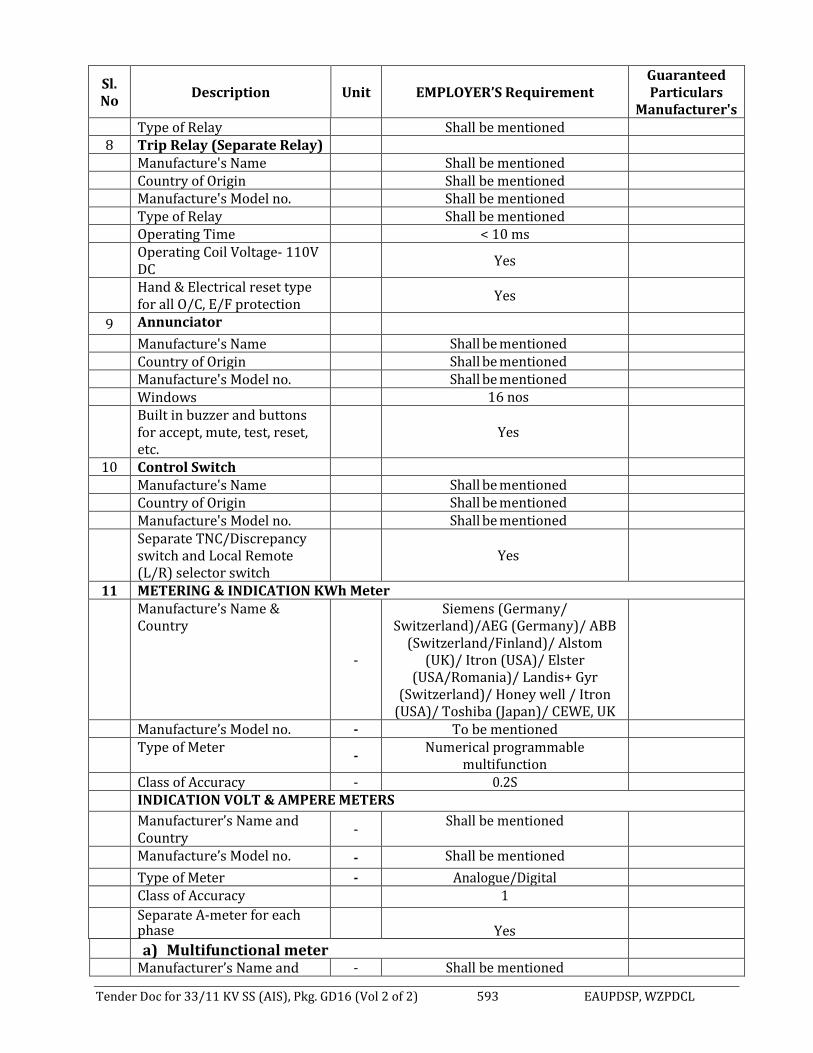
Tender Doc for 33/11 KV SS (AIS), Pkg. GD16 (Vol 2 of 2) 593 EAUPDSP, WZPDCL
Sl. No
Description Unit EMPLOYER’S Requirement Guaranteed Particulars
Manufacturer's Type of Relay Shall be mentioned
8 Trip Relay (Separate Relay) Manufacture's Name Shall be mentioned Country of Origin Shall be mentioned Manufacture's Model no. Shall be mentioned Type of Relay Shall be mentioned Operating Time < 10 ms
Operating Coil Voltage- 110V DC
Yes
Hand & Electrical reset type for all O/C, E/F protection
Yes
9 Annunciator
Manufacture's Name Shall be mentioned Country of Origin Shall be mentioned Manufacture's Model no. Shall be mentioned Windows 16 nos
Built in buzzer and buttons for accept, mute, test, reset, etc.
Yes
10 Control Switch Manufacture's Name Shall be mentioned Country of Origin Shall be mentioned Manufacture's Model no. Shall be mentioned
Separate TNC/Discrepancy switch and Local Remote (L/R) selector switch
Yes
11 METERING & INDICATION KWh Meter
Manufacture’s Name & Country
-
Siemens (Germany/ Switzerland)/AEG (Germany)/ ABB
(Switzerland/Finland)/ Alstom (UK)/ Itron (USA)/ Elster
(USA/Romania)/ Landis+ Gyr (Switzerland)/ Honey well / Itron
(USA)/ Toshiba (Japan)/ CEWE, UK
Manufacture’s Model no. - To be mentioned
Type of Meter
- Numerical programmable
multifunction
Class of Accuracy - 0.2S
INDICATION VOLT & AMPERE METERS
Manufacturer’s Name and Country
- Shall be mentioned
Manufacture’s Model no. - Shall be mentioned
Type of Meter - Analogue/Digital
Class of Accuracy 1
Separate A-meter for each phase
Yes
a) Multifunctional meter
Manufacturer’s Name and - Shall be mentioned

Tender Doc for 33/11 KV SS (AIS), Pkg. GD16 (Vol 2 of 2) 594 EAUPDSP, WZPDCL
Sl. No
Description Unit EMPLOYER’S Requirement Guaranteed Particulars
Manufacturer's Country Manufacture’s Model no. - Shall be mentioned Type of Meter - Digital, Import/Export
Parameters: capable of measuring and displaying MW, MVAR, PF, V, I, f, Φ etc.
Yes
Class of Accuracy 1 12 Overall dimensions of each Panel unit:
a) - Height
- Width - Depth
mm mm mm
2200 To be mentioned To be mentioned
Seal & Signature of the manufacturer Seal & Signature of the Tenderer

Tender Doc for 33/11 KV SS (AIS), Pkg. GD16 (Vol 2 of 2) 595 EAUPDSP, WZPDCL
8.13 GUARANTEED TECHNICAL PARTICULARS OF 11KV INDOOR AIR INSULATED SWITCHGEAR CUBICLES WITH BREAKER, PROTECTION, CONTROL & METERING CUBICLES.
(To be filled up by the Manufacturer in Manufacturer Letterhead Pad, otherwise the bid shall be rejected)
Sl. No.
Description Unit WZPDCL's
Requirement
Manufacturer's Guaranteed Particulars
1. Manufacturer's Name & Country of origin - To be mentioned
2. Manufacturer's Model no. - To be mentioned
3. System nominal voltage kV 11
4. Maximum System Voltage kV 12
5. Rated Frequency Hz 50
6 Circuit Breaker
Rated normal current:
a) Incoming for 10/13.33 MVA Transformer
1600
b) bus Coupler A 1600
c) Outgoing Feeder A 630
7. No. of phase nos. 3
8. No. of breaks per phase nos. To be mentioned
9. Interrupting medium - Vacuum
10. Manufacturer's name and country of origin of Vacuum Interrupter
- To be mentioned
11. Manufacturer's model no. of vacuum interrupter
- To be mentioned
12. Power Frequency withstand voltage kV 28
13. Lightning Impulse withstand voltage on 1.2/50 s wave
kV 75
14. Emergency overload rating of normal at 200C ambient
- To be mentioned
15. Duration in any 24 hrs. period - To be mentioned
16 Current Transformer:
Accuracy Class, Metering 0.2S
Accuracy Class, Protection 5P20
Rated Current Ratio (for Transformer incoming)
A 800-1600/5-5A
Rated Current Ratio (for Bus coupler) A 800-1600/5-5A
Rated Current Ratio (for Outgoing feeder) A 200-400/5-5A
Burden for metering VA 30
Burden for protection VA 30
17. Busbar Scheme no. Single
18. Number of Busbar nos. 3
19. Temperature Rise of Busbar at rated current
0C To be mentioned
20. Material of Busbar - Copper
21. Cross-section of Busbar mm2 To be mentioned

Tender Doc for 33/11 KV SS (AIS), Pkg. GD16 (Vol 2 of 2) 596 EAUPDSP, WZPDCL
Sl. No.
Description Unit WZPDCL's
Requirement
Manufacturer's Guaranteed Particulars
22. Rated normal current of bus bar for 10/13.33 MVA S/S
A 1600
23. Bus bar insulation material - To be mentioned
24. Are floor plates or rails included? - To be mentioned
25. Overall dimensions of each circuit breaker unit:
a) Incomer: -
- Height
- Width
- Depth
mm
mm
mm
To be mentioned
To be mentioned
To be mentioned
b) Feeder: -
- Height
- Width - Depth
mm
mm mm
To be mentioned
To be mentioned To be mentioned
c) Bus coupler: -
- Height
- Width
- Depth
mm
mm
mm
To be mentioned
To be mentioned
To be mentioned
26. Width necessary for breaker withdrawal mm To be mentioned
27. Rated Short-time withstand Current (Rated short circuit breaking current) for 3 sec.
KA min 25
28. Rated Peak withstand Current (Rated short circuit making current)
KA min 62.5
29. Breaking capacity:
a) Symmetrical rms
b) Asymmetrical rms
KA
KA
25
As per IEC
30. Rated duration of short circuit Sec. 3sec
31. Degrees of protection by enclosures IP IP4X
32. First pole to clear factor - To be mentioned
33. Rate transient recovery voltage at 100% rated short circuit breaking current
KVp To be mentioned
34. Rated line charging breaking current A To be mentioned
35. Rated cable charging breaking current A To be mentioned
36. Rated out of phase breaking current A To be mentioned
37. Is circuit breaker re-strike free? - Yes
38. No. of tripping coil nos. 2
39. Trip coil current A To be mentioned
40. Trip coil voltage VDC 110
41. Is circuit breaker trip free? - Yes
42. Type of main contact - To be mentioned
43. Material of contact surface - To be mentioned
44. Contact resistance < 40

Tender Doc for 33/11 KV SS (AIS), Pkg. GD16 (Vol 2 of 2) 597 EAUPDSP, WZPDCL
Sl. No.
Description Unit WZPDCL's
Requirement
Manufacturer's Guaranteed Particulars
45. Does magnetic effect of load current increase contact?
- To be mentioned
46. Length of each break/ phase mm To be mentioned
47. Length of stroke mm To be mentioned
48. Weight of circuit breaker complete, without operating mechanism and cubicles
Kg To be mentioned
49. Weight of circuit breaker complete with PCM cubicles as in service
Kg To be mentioned
50. Maximum shock load imposed on floor or foundation when opening under fault condition (state compression or tensions)
N To be mentioned
OPERATING:
51. Operating Sequence - To be mentioned
52. a) Opening time without current at 100% of rated breaking current
b) Braking time
c) Closing time
ms
cycle
ms
0.05 (maximum)
2 or 3 cycles
To be mentioned
53. Maximum arc duration of any duty cycle as per latest revision of relevant IEC.
ms at....%
To be mentioned
54. Current at which maximum arc duration occurs (critical current)
A To be mentioned
55. Make time ms To be mentioned
56. Minimum time for arc extinction to contact remake when adapted for auto re-closing
ms To be mentioned
57. Time from closing of control of switch to completion of closing stroke during fault making.
ms To be mentioned
58. Is there anti-pumping facility? - Yes
59. Is there electrical and mechanical interlocking?
- Yes
60. Pressure in vacuum tube bar To be mentioned
61. Guaranteed no. of operation for vacuum interrupter
nos. To be mentioned
62. In normal condition at rated current switching
nos. To be mentioned
63. In short circuit condition i.e. at the short circuit current switching
nos. ≥ 50
64 Circuit Breaker Class shall be (through necessary type test Report)
- E2, M2 Class
CONSTRUCTION FEATURE:
65. Is an external series break incorporated in the breaker?
- To be mentioned

Tender Doc for 33/11 KV SS (AIS), Pkg. GD16 (Vol 2 of 2) 598 EAUPDSP, WZPDCL
Sl. No.
Description Unit WZPDCL's
Requirement
Manufacturer's Guaranteed Particulars
66. Is any device used to limit transient recovery voltage?
- To be mentioned
67. Method of closing - To be mentioned
68. Method of tripping - To be mentioned
69. Minimum clearance in air:
a) between phases
b) phase to earth
mm
mm
To be mentioned
To be mentioned
70. Material of tank or chamber - To be mentioned
71. Material of moving contact tension rod - To be mentioned
72. Period of time equipment has been in commercial operation
Years To be mentioned
73. Is removable draw-out type VCB mounted on the lower part of the panel i.e. on floor/ medium part of the panel ie trolley type?
- To be mentioned
74. All meters, protective relays, signaling etc. mounted on the upper part of the panel.
- To be mentioned
75. Rates voltage of spring winding motor for closing.
Vac 240
76. Materials of all current carrying parts of VCB.
- Copper
77. Name of relevant IEC Standards to be followed fin Design, Manufacture, Testing and Performance.
- To be mentioned
78 For 11 KV outgoing feeders having gang operated earth switch
Yes
PROTECTION
A. 33/11KV, 10/ 13.33 MVA, 11KV TRANSFORMER INCOMING CUBICLES
79.0 Over Current and Earth Fault protection with IDMT & Instantaneous features Manufacturer’s Name
(To be mentioned only one within scope)
ABB- (Sweden/ Finland) /Siemens –
Germany (except 7SR series) /
Schneider- (France/ UK / Finland)/ GE
(UK/France /Canada)
Manufacture's model no. - To be mentioned Type of relay - Numerical
programmable with all necessary
features (IED)
Range of timing settings at 10-time CT rating
Sec To be mentioned
Burden of relay at 10-time CT rating VA To be mentioned

Tender Doc for 33/11 KV SS (AIS), Pkg. GD16 (Vol 2 of 2) 599 EAUPDSP, WZPDCL
Sl. No.
Description Unit WZPDCL's
Requirement
Manufacturer's Guaranteed Particulars
Percentage of current setting at which relay will reset
% To be mentioned
Reset time after removal of 10-time CT rated current for: a) Phase element (100%) b) E/F element (40%)
Sec Sec
To be mentioned To be mentioned
Communication Facilities SCADA Supported
Communication Standard IEC-61850 with FO-LC Port
Features: 16 BI, 11 BO, Mimic Display, and others as per section-7 of technical specification.
Yes
80 Trip Circuit Supervision (TCS) Relay (Separate Relay for each trip coil) Manufacture's Name Shall be mentioned Country of Origin Shall be mentioned Manufacture's Model no. Shall be mentioned Type of Relay Shall be mentioned 81 Trip Relay (Separate Relay) Manufacture's Name Shall be mentioned Country of Origin Shall be mentioned Manufacture's Model no. Shall be mentioned Type of Relay Shall be mentioned Operating Time < 10 ms Operating Coil Voltage- 110V DC Yes All O/C, E/F protection Hand & Electrical
reset type. Yes
82 Control Switch Manufacture's Name Shall be mentioned Country of Origin Shall be mentioned Manufacture's Model no. Shall be mentioned Separate TNC/Discrepancy switch and
Local Remote (L/R) selector switch
Yes
83 Annunciator Manufacture's Name Shall be mentioned Country of Origin Shall be mentioned Manufacture's Model no. Shall be mentioned Windows 16 nos Built in buzzer and buttons for accept,
mute, test, reset, etc.
Yes
B 11KV Bus Cubicles 84.0 Over Current and Earth Fault protection with IDMT & Instantaneous
features

Tender Doc for 33/11 KV SS (AIS), Pkg. GD16 (Vol 2 of 2) 600 EAUPDSP, WZPDCL
Sl. No.
Description Unit WZPDCL's
Requirement
Manufacturer's Guaranteed Particulars
Manufacturer’s Name (To be mentioned only one within scope)
ABB- (Sweden/ Finland) /Siemens –
Germany (except 7SR series) /
Schneider- (France/ UK / Finland)/ GE
(UK/France /Canada)
Manufacture's model no. - To be mentioned Type of relay - Numerical
programmable (IED)
Range of current setting: a) Phase element b) Earth fault element
% of CT
rating
To be mentioned To be mentioned
Range of timing settings at 10-time CT rating
Sec To be mentioned
Burden of relay at 10-time CT rating VA To be mentioned Percentage of current setting at which
relay will reset %
To be mentioned
Reset time after removal of 10-time CT rated current for: a) Phase element (100%) b) E/F element (40%)
Sec Sec
To be mentioned To be mentioned
Communication Facilities SCADA Supported Communication Standard IEC-61850 with FO-
LC Port
Features: 16 BI, 11 BO, Mimic Display, and others as per section-7 of technical specification.
Yes
85 Trip Circuit Supervision (TCS) Relay (Separate Relay for each trip coil) Manufacture's Name Shall be mentioned Country of Origin Shall be mentioned Manufacture's Model no. Shall be mentioned Type of Relay Shall be mentioned 86 Trip Relay (Separate Relay) Manufacture's Name Shall be mentioned Country of Origin Shall be mentioned Manufacture's Model no. Shall be mentioned Type of Relay Shall be mentioned Operating Time < 10 ms Operating Coil Voltage- 110V DC Yes All O/C, E/F protection Hand & Electrical
reset type. Yes
87 Control Switch Manufacture's Name Shall be mentioned Country of Origin Shall be mentioned Manufacture's Model no. Shall be mentioned Separate TNC/Discrepancy switch and
Local Remote (L/R) selector switch
Yes

Tender Doc for 33/11 KV SS (AIS), Pkg. GD16 (Vol 2 of 2) 601 EAUPDSP, WZPDCL
Sl. No.
Description Unit WZPDCL's
Requirement
Manufacturer's Guaranteed Particulars
88 Annunciator Manufacture's Name Shall be mentioned Country of Origin Shall be mentioned Manufacture's Model no. Shall be mentioned Windows 16 nos Built in buzzer and buttons for accept,
mute, test, reset, etc.
Yes
C 11KV Outgoing Feeder Cubicles 89 Over Current and Earth Fault protection with IDMT & Instantaneous features Manufacture's name & country of relay - Siemens (Germany)
/ ABB (Switzerland/ Sweden/Finland)/ Schneider Electric (Uk/ France)/ GE
(UK/France/ Canada)/ Alstom
(Uk/ France)
Manufacture's model no. - To be mentioned Type of relay - Numerical
programmable (IED)
Range of current setting: a) Phase element b) Earth fault element
% of CT
rating
To be mentioned To be mentioned
Range of timing settings at 10-time CT rating
Sec To be mentioned
Burden of relay at 10-time CT rating VA To be mentioned Percentage of current setting at which
relay will reset %
To be mentioned
Reset time after removal of 10-time CT rated current for: a) Phase element (100%) b) E/F element (40%)
Sec Sec
To be mentioned To be mentioned
Communication Facilities SCADA Supported Communication Standard IEC-61850 with FO-
LC Port
Features: 16 BI, 11 BO, Mimic Display, and others as per section-7 of technical specification.
Yes
90 Trip Circuit Supervision (TCS) Relay (Separate Relay for each trip coil) Manufacture's Name Shall be mentioned Country of Origin Shall be mentioned Manufacture's Model no. Shall be mentioned Type of Relay Shall be mentioned 91 Trip Relay (Separate Relay) Manufacture's Name Shall be mentioned Country of Origin Shall be mentioned Manufacture's Model no. Shall be mentioned Type of Relay Shall be mentioned Operating Time < 10 ms

Tender Doc for 33/11 KV SS (AIS), Pkg. GD16 (Vol 2 of 2) 602 EAUPDSP, WZPDCL
Sl. No.
Description Unit WZPDCL's
Requirement
Manufacturer's Guaranteed Particulars
Operating Coil Voltage- 110V DC Yes All O/C, E/F protection Hand & Electrical
reset type. Yes
92 Control Switch Manufacture's Name Shall be mentioned Country of Origin Shall be mentioned Manufacture's Model no. Shall be mentioned Separate TNC/Discrepancy switch and
Local Remote (L/R) selector switch
Yes
93 Annunciator Manufacture's Name Shall be mentioned Country of Origin Shall be mentioned Manufacture's Model no. Shall be mentioned Windows 12 nos Built in buzzer and buttons for accept,
mute, test, reset, etc.
Yes
D METERING AND INDICATION FOR 33/11KV, 10/13.33 MVA TRANSFORMER 11KV INCOMING AND
11KV OUTGOING FEEDER 94 KWh Meter Manufacture’s Name & Country - Siemens (Germany)/
ABB (Switzerland /Finland)
AEG(Germany)/ Itron(USA)
/Elster(USA/ Romania)
/Landis+gyr, (Switzerland)/
Toshiba (Japan)/ Honeywell (USA)/
CEWE, UK
Manufacture’s Model no. - To be mentioned Type of meter - Numerical
Programmable Multifunction
Class of accuracy - 0.2S 95 INDICATION VOLT METERS & AMMETERS Manufacturer’s Name and Country - To be mentioned Manufacture’s Model no. - To be mentioned Type of meter - Analogue/ Digital Class of Accuracy - 1 96 VOLTMETER WITH SELECTOR SWITCH Manufacturer’s Name and Country To be mentioned Manufacture’s Model no. To be mentioned Type of meter Analogue / Digital Class of Accuracy 1.0 Only for 11 KV incomer PCM Panels. Yes 97 Multifunctional meter Manufacturer’s Name and Country - Shall be mentioned

Tender Doc for 33/11 KV SS (AIS), Pkg. GD16 (Vol 2 of 2) 603 EAUPDSP, WZPDCL
Sl. No.
Description Unit WZPDCL's
Requirement
Manufacturer's Guaranteed Particulars
Manufacture’s Model no. - Shall be mentioned
Type of Meter
- Digital,
Import/Export
Parameters: capable of measuring and displaying MW, MVAR, PF, V, I, f, Φ etc.
Yes
Class of Accuracy 1.0
98 Capacitive Voltage Divider (CVD) based Live Line Indicator (LLI) for each panel
Yes
99 The Switchgear and PCM Panel Shall be complied all the technical specification mentioned in Section-7
Yes
Manufacturer Seal and signature Tenderers Seal and signature

Tender Doc for 33/11 KV SS (AIS), Pkg. GD16 (Vol 2 of 2) 604 EAUPDSP, WZPDCL
8.14 GUARANTEED TECHNICAL PARTICULARS OF 110V 3 X 5(6) A, 3-PHASE 4-WIRE, 3-ELEMENT, SOLID STATE INDOOR TYPE MULTI TARIFF PROGRAMMABLE METER
(To be filled up by the Manufacturer in Manufacturer Letterhead Pad, otherwise the bid shall be rejected.)
Sl No
Description Unit EMPLOYER’S Requirement
Manufacturer's Guaranteed Particulars
01 Reference standard Relevant ANSI /IEC standard
02 Manufacturer’s name & address Siemens (Germany/ Switzerland)/ ABB
(Switzerland) /Finland AEG (Germany)/
Itron(USA) /Elster (USA/Romania)
/Landis +gyr, (Switzerland/Greece)/
Toshiba (Japan)/ Honeywell (USA)/
CEWE, UK
03 Manufacturer’s type & model To be mentioned
04 Construction / Connection 3-phase, 4-wire solidly grounded neutral
05 Installation Indoor Installation in A socket [for socket
type]
06 Number of elements 3
07 Rated voltage Volt 110
08 Minimum Biasing Voltage Volt 40
09 Variation of frequency % +2
10 Variation of voltage % +10, -20
11 Accuracy class 0.2S (point two)
12 Rated current I) Basic current II) Maximum current
A A
5A 6A
13 Register type LCD Display
14 Number of digit (integer) Nos. 7 with 1 (Programmable)
15 Starting current mA 0.1% of Nominal Current
16 Losses at nominal load Watt & VA
To be mentioned
17 Meter constant Imp. / KWh.
To be mentioned
18 Integration period Resetting period Cumulative MD transfer cycle timing device
30 (thirty) minutes 1 (one) month
Built-in Built-in
19 Size of the digit of display W x H in 4 X 8

Tender Doc for 33/11 KV SS (AIS), Pkg. GD16 (Vol 2 of 2) 605 EAUPDSP, WZPDCL
Sl No
Description Unit EMPLOYER’S Requirement
Manufacturer's Guaranteed Particulars
mm 20 No. of terminal Nos. 10 (Minimum) 21 Type of Socket/enclosure and
Country of origin
To be mentioned
22 Battery service life and Shelf life Year 10(Ten) & 15 (fifteen) 23 Year of manufacture To be mentioned 24 List of recommended spare parts
(If any)
To be mentioned
25 Warranty Year 3 (Three) 26 Meter Service life (minimum) Year 15 (fifteen) 27 Weight of meter Kg To be mentioned 28 Dimensions mm x
mm x mm
To be mentioned
29 Outlines, drawings & leaflets To be mentioned 30 Performance curve for balanced &
unbalanced load
To be mentioned
31 Meter sealing condition Hermetically or Ultrasonic welded
32 a) Country of origin b) Place of manufacture c) Place of testing
To be mentioned
33 Memory storage
Shall To be mentioned by putting Yes / No
i) Equipment identification
code. ii) Security code iii) Access code iv) Number of power
interruption with date & time
v) Latest power failure time & date
vi) Event log. vii) Cumulative KWh, KVarh
(Q1+Q4) reading viii) Load Profile with 30 min
interval at least 90 days for:
KWh, kVarh (Q1+Q4) Phase voltage or Vh Phase amps or Ah
34 Communication Facilities RE, RS 232, RS 485, RJ45, DLMS/ COSEM,
GSM-GPRS and Modbus or IEC 61850.
35 GSM-GPRS Modem Yes
Seal & Signature of the manufacturer: Seal & Signature of the Tenderer:

Tender Doc for 33/11 KV SS (AIS), Pkg. GD16 (Vol 2 of 2) 606 EAUPDSP, WZPDCL
8.15 MANUFACTURER’S GUARANTEED TECHNICAL DATA SCHEDULE FOR 11KV INDOOR TYPE SINGLE PHASE CURRENT TRANSFORMER
(To be filled up by the Manufacturer in Manufacturer Letterhead Pad, otherwise the bid shall be rejected.)
Sl. No.
Description Unit WZPDCL's
Requirement
Manufacturer's guaranteed Particulars
FOR PROTECTION & METERING: 1 Manufacturer’s name & country - To be mentioned 2 Manufacturer’s model no. - To be mentioned Application - Metering & Protection 3 Installation - Indoor 4 Mounting - On transformer
incoming pane / separate PT panel
5 Primary Rated Voltage (Phase to Phase) kV 11 6 Maximum System Voltage (Phase to Phase) kV 12 7 Basic Insulation Level (1.2/50 Micro-sec.) kV 75 8 Power Frequency Withstand Voltage (1
Min. 50 Hz). kV 28
Ratio: Ratio for Outgoing feeder: 200-400/5-5A Ratio for Power Transformer incomer 800-1600/5-5A Ratio for Bus Coupler: 800-1600/5-5A 10 Type of Winding: a) Primary - Single Winding b) Secondary - Double (1 protection &
1 measuring)
11 Rated output for Incoming panel a) for measurement VA 30 b) for Protection VA 30 12 Rated output for outgoing panel a) for measurement VA 30 b) for Protection VA 30 13 Accuracy class a) for measurement - 0.2S b) for Protection
- 11kV Transformer Incomer - 11kV Outgoing/ transformer feeder
- -
5P20 5P20
14 Rated short time thermal current, for 3 sec. KA 25 15 Rate accuracy limit factor - To be mentioned 16 RCT at 75˚ C
For Measuring Core For Protection Core
mΩ mΩ
To be mentioned To be mentioned
17 Knee point voltage For Measuring Core For Protection Core
V V
To be mentioned To be mentioned
18 Extended Current Rating (% of rated current)
% 120
19. Major insulation - Epoxy resin

Tender Doc for 33/11 KV SS (AIS), Pkg. GD16 (Vol 2 of 2) 607 EAUPDSP, WZPDCL
20 Name of relevant IEC Standards to be followed for Design, Manufacture, Testing and Performance.
- To be mentioned
21 Creepage Distance Shall be mentioned
Seal & Signature of the Manufacturer Seal & Signature of the Tenderer

Tender Doc for 33/11 KV SS (AIS), Pkg. GD16 (Vol 2 of 2) 608 EAUPDSP, WZPDCL
8.16 MANUFACTURER’S GUARANTEED TECHNICAL DATA SCHEDULE FOR 11KV INDOOR TYPE SINGLE PHASE POTENTIAL TRANSFORMER
(To be filled up by the Manufacturer in Manufacturer Letterhead Pad, otherwise the bid shall be rejected.)
Sl. No. Description Unit WZPDCL's
Requirement
Manufacturer's Guaranteed Particulars
1. Manufacturer’s Name and country - To be mentioned
2. Manufacturer’s Model no. - To be mentioned
3. Type - Induction type
4. Ratio V 11000/3:110/3:
110/3
5.
Rated Burden:
a) for measurement VA 30
b) for Protection VA 30
6.
Class of accuracy:
a) for measurement VA 0.2
b) for Protection VA 3P
7 No. of phase no. Single phase
8. No. of secondary winding nos. To be mentioned
9. Creepage distance (min) mm/KV 25
10. Total weight Kg To be mentioned
11. Insulation - Epoxy resin
12. Name of relevant IEC Standards to be followed for Design, Manufacture, Testing and Performance.
- To be mentioned
Seal & Signature of the Manufacturer Seal & Signature of the Tenderer

Tender Doc for 33/11 KV SS (AIS), Pkg. GD16 (Vol 2 of 2) 609 EAUPDSP, WZPDCL
8.17 GUARANTEED TECHNICAL PARTICULARS OF 11KV, 1-CORE, 500 mm² UNDERGROUND
XLPE COPPER CABLE
(To be filled up by the Manufacturer in Manufacturer Letterhead Pad, otherwise the bid shall be rejected.)
Sl. No
DESCRIPTION UNIT WZPDCL REQUIREMENT TENDERER'S GUARANTEED
VALUES
1 Name & address of the Manufacturer To be mentioned
2 Type/Model of the offered Cable To be mentioned
3 Standards
Performance, Design and testing shall be in
accordance to the IEC, BS, BDS or equivalent
international standards
4 Nominal System Voltage KV 33
5 Rated voltage of Cable KV 18/30 (36)
6 Process of manufacturing VCV/CCV
7 Number of core and Cross-Sectional area of conductor cores
Sq.mm 1C x 500
8 Conductor materials Copper
9 Number of strands Nos To be mentioned
11 Diameter of each strand mm To be mentioned
12 Shape of conductor Compacted Circular
13 Type of non-metallic conductor screen Semi-conducting
14 Thickness of semi-conducting conductor screen
mm ≤ 0.7
15 Nominal diameter of Al wire Armour mm ≥ 2.5
16 Average thickness of insulation mm ≥ 8.00
17 Process of curing Dry process
18 Material of Insulation Cross-Linked Poly-
ethylene (XLPE)
19 Type of non-metallic insulating screen Semi-conducting
20 Thickness of semi-conducting Insulation screen
mm ≥ 0.7
21 Number and diameter of copper Screen strands
No/ mm To be mentioned
(Based on design calculation)
22 Composition of filler PVC
23 Composition of bedding Extruded PVC
24 Thickness of bedding mm To be mentioned
(Based on design calculation)
25 Number & diameter of amour wire
or Thickness of corrugated aluminum sheath
No./ mm Or
mm
To be mentioned (Based on design calculation)
26 Average thickness of MDPE over sheath mm To be mentioned
(Based on design calculation)
27 Nominal diameter of complete cable mm To be mentioned
(Based on design calculation)

Tender Doc for 33/11 KV SS (AIS), Pkg. GD16 (Vol 2 of 2) 610 EAUPDSP, WZPDCL
28 Nominal weight per meter of Complete cable
Kg/m To be mentioned
(Based on design calculation)
29 Minimum radius of bend round which cable can be laid
mm To be mentioned
(Based on design calculation)
30 Maximum D.C. resistance of Conductor per kilometer at 20° C
Ohm/km 0.0366
31 Maximum A.C. resistance of Conductor per meter at a maximum conductor temperature of 90° C
Ohm/m To be mentioned
(Based on design calculation)
32 Reactance per kilometer of cable at 50 Hz ohm/Km 0.102
33 Maximum Star capacitance per kilometer of cable at 50 Hz
µF/Km 0.628
34 Charging current per conductor per meter at 18000/30000 Volts, 50 Hz
mA To be mentioned
(Based on design calculation)
35 Maximum current carrying capacity of conductor in ground A
To be mentioned (Based on design calculation)
36 Maximum conductor temperature under continuous loading
°C To be mentioned
(Based on design calculation)
37 Short- circuit withstand capacity of the cable for 1 sec. duration
kA 71.54
38 Conductor temperature at the end of short circuit.
° C 250
39 Metallic Screen short circuit withstand capacity for 1 second
kA 25 (with detail calculation)
40 Cable resistance & reactance:
a) For positive sequence Ohm/km To be mentioned
(Based on design calculation)
b) Negative sequence Ohm/km To be mentioned
(Based on design calculation)
c) Zero sequence Ohm/km To be mentioned
(Based on design calculation)
Seal & Signature of the Manufacturer Seal & Signature of the Tenderer
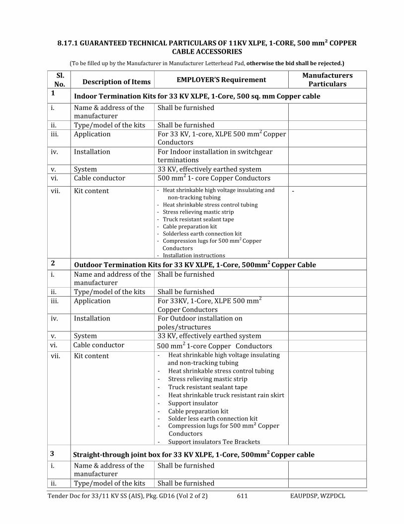
Tender Doc for 33/11 KV SS (AIS), Pkg. GD16 (Vol 2 of 2) 611 EAUPDSP, WZPDCL
8.17.1 GUARANTEED TECHNICAL PARTICULARS OF 11KV XLPE, 1-CORE, 500 mm² COPPER
CABLE ACCESSORIES
(To be filled up by the Manufacturer in Manufacturer Letterhead Pad, otherwise the bid shall be rejected.)
Sl. No.
Description of Items EMPLOYER’S Requirement Manufacturers
Particulars 1 Indoor Termination Kits for 33 KV XLPE, 1-Core, 500 sq. mm Copper cable
i. Name & address of the manufacturer
Shall be furnished
ii. Type/model of the kits Shall be furnished iii. Application For 33 KV, 1-core, XLPE 500 mm2 Copper
Conductors
iv. Installation For Indoor installation in switchgear terminations
v. System 33 KV, effectively earthed system vi. Cable conductor 500 mm2 1- core Copper Conductors
vii. Kit content - Heat shrinkable high voltage insulating and non-tracking tubing
- Heat shrinkable stress control tubing - Stress relieving mastic strip - Truck resistant sealant tape - Cable preparation kit - Solderless earth connection kit - Compression lugs for 500 mm2 Copper
Conductors - Installation instructions
-
2 Outdoor Termination Kits for 33 KV XLPE, 1-Core, 500mm2 Copper Cable i. Name and address of the
manufacturer Shall be furnished
ii. Type/model of the kits Shall be furnished iii. Application For 33KV, 1-Core, XLPE 500 mm2
Copper Conductors
iv. Installation For Outdoor installation on poles/structures
v. System 33 KV, effectively earthed system vi. Cable conductor 500 mm2 1-core Copper Conductors
vii. Kit content - Heat shrinkable high voltage insulating and non-tracking tubing
- Heat shrinkable stress control tubing - Stress relieving mastic strip - Truck resistant sealant tape - Heat shrinkable truck resistant rain skirt - Support insulator - Cable preparation kit - Solder less earth connection kit - Compression lugs for 500 mm² Copper
Conductors - Support insulators Tee Brackets
- Installation instructions
3 Straight-through joint box for 33 KV XLPE, 1-Core, 500mm2 Copper cable
i. Name & address of the manufacturer
Shall be furnished
ii. Type/model of the kits Shall be furnished

Tender Doc for 33/11 KV SS (AIS), Pkg. GD16 (Vol 2 of 2) 612 EAUPDSP, WZPDCL
Sl. No.
Description of Items EMPLOYER’S Requirement Manufacturers
Particulars iii. Application For 33 KV, 1-core, XLPE 500mm2 Copper
Conductors
iv. Installation For underground horizontal mounting
v. System 33 KV, effectively earthed system vi. Cable conductor 500 mm2 1-core Copper Conductor
vii. Construction The joint shall be proof against Ingress of moisture and water
viii. Kit content - Compression ferrules - Valid filling tape - Heat shrinkable stress control tubing - Truck resistant sealant tape - Heat shrinkable high voltage insulating tape - Heat shrinkable black/red dual wall - Estomeric tube - Roll spring - Heat shrinkable outer jacket tube - Cable preparation kit - Solderless earth connection kit - Misc. other material - Installation instructions
Seal & Signature of the Manufacturer Seal & Signature of the Tenderer
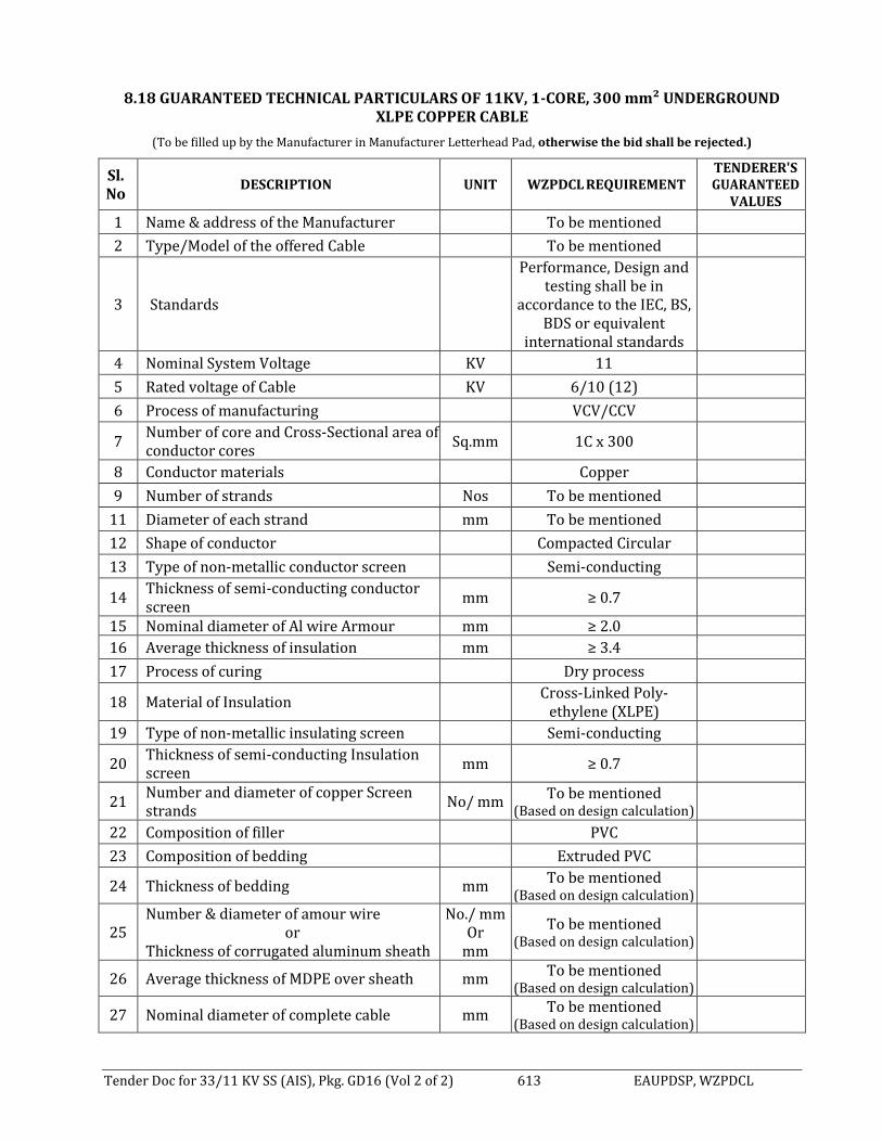
Tender Doc for 33/11 KV SS (AIS), Pkg. GD16 (Vol 2 of 2) 613 EAUPDSP, WZPDCL
8.18 GUARANTEED TECHNICAL PARTICULARS OF 11KV, 1-CORE, 300 mm² UNDERGROUND
XLPE COPPER CABLE
(To be filled up by the Manufacturer in Manufacturer Letterhead Pad, otherwise the bid shall be rejected.)
Sl. No
DESCRIPTION UNIT WZPDCL REQUIREMENT TENDERER'S GUARANTEED
VALUES
1 Name & address of the Manufacturer To be mentioned
2 Type/Model of the offered Cable To be mentioned
3 Standards
Performance, Design and testing shall be in
accordance to the IEC, BS, BDS or equivalent
international standards
4 Nominal System Voltage KV 11
5 Rated voltage of Cable KV 6/10 (12)
6 Process of manufacturing VCV/CCV
7 Number of core and Cross-Sectional area of conductor cores
Sq.mm 1C x 300
8 Conductor materials Copper
9 Number of strands Nos To be mentioned
11 Diameter of each strand mm To be mentioned
12 Shape of conductor Compacted Circular
13 Type of non-metallic conductor screen Semi-conducting
14 Thickness of semi-conducting conductor screen
mm ≥ 0.7
15 Nominal diameter of Al wire Armour mm ≥ 2.0
16 Average thickness of insulation mm ≥ 3.4
17 Process of curing Dry process
18 Material of Insulation Cross-Linked Poly-
ethylene (XLPE)
19 Type of non-metallic insulating screen Semi-conducting
20 Thickness of semi-conducting Insulation screen
mm ≥ 0.7
21 Number and diameter of copper Screen strands
No/ mm To be mentioned
(Based on design calculation)
22 Composition of filler PVC
23 Composition of bedding Extruded PVC
24 Thickness of bedding mm To be mentioned
(Based on design calculation)
25 Number & diameter of amour wire
or Thickness of corrugated aluminum sheath
No./ mm Or
mm
To be mentioned (Based on design calculation)
26 Average thickness of MDPE over sheath mm To be mentioned
(Based on design calculation)
27 Nominal diameter of complete cable mm To be mentioned
(Based on design calculation)

Tender Doc for 33/11 KV SS (AIS), Pkg. GD16 (Vol 2 of 2) 614 EAUPDSP, WZPDCL
28 Nominal weight per meter of Complete cable
Kg/m To be mentioned
(Based on design calculation)
29 Minimum radius of bend round which cable can be laid
mm To be mentioned
(Based on design calculation)
30 Maximum D.C. resistance of Conductor per kilometer at 20° C
Ohm/km <.0601
31 Maximum A.C. resistance of Conductor per meter at a maximum conductor temperature of 90° C
Ohm/m To be mentioned
(Based on design calculation)
32 Inductance per kilometer of cable at 50 Hz
mH/Km 0.336
33 Star capacitance per meter of cable at 50 Hz
mF/km Approximate 0.50
34 Charging current per conductor per meter at 18000/30000 Volts, 50 Hz
mA To be mentioned
(Based on design calculation)
35 Maximum current carrying capacity of conductor in ground A
To be mentioned (Based on design calculation)
36 Maximum conductor temperature under continuous loading
°C To be mentioned
(Based on design calculation)
37 Short- circuit withstand capacity of the cable for 1 sec. duration
kA 42.92
38 Conductor temperature at the end of short circuit.
° C 250
39 Metallic Screen short circuit withstand capacity for 1 second
kA 25 (with detail calculation)
40 Cable resistance & reactance:
a) For positive sequence Ohm/km To be mentioned
(Based on design calculation)
b) Negative sequence Ohm/km To be mentioned
(Based on design calculation)
c) Zero sequence Ohm/km To be mentioned
(Based on design calculation)
Seal & Signature of the Manufacturer Seal & Signature of the Tenderer

Tender Doc for 33/11 KV SS (AIS), Pkg. GD16 (Vol 2 of 2) 615 EAUPDSP, WZPDCL
8.18.1 GUARANTEED TECHNICAL PARTICULARS OF 11KV XLPE, 1-CORE, 300 mm² COPPER
CABLE ACCESSORIES
(To be filled up by the Manufacturer in Manufacturer Letterhead Pad, otherwise the bid shall be rejected.)
Sl. No.
Description of Items EMPLOYER’S Requirement Manufacturers
Particulars 1 Indoor Termination Kits for 11 KV XLPE, 1-Core, 300 sq. mm Copper cable
i. Name & address of the manufacturer
Shall be furnished
ii. Type/model of the kits Shall be furnished iii. Application For 11 KV, 1-core, XLPE 300 mm2
Copper Conductors
iv. Installation For Indoor installation in switchgear terminations
v. System 11 KV, effectively earthed system vi. Cable conductor 300 mm2 1- core Copper Conductors
vii. Kit content - Heat shrinkable high voltage insulating and non-tracking tubing
- Heat shrinkable stress control tubing - Stress relieving mastic strip - Truck resistant sealant tape - Cable preparation kit - Solderless earth connection kit - Compression lugs for 300 mm2 Copper
Conductors - Installation instructions
-
2 Outdoor Termination Kits for 11KV XLPE, 1-Core, 300mm2 Copper Cable i. Name and address of the
manufacturer Shall be furnished
ii. Type/model of the kits Shall be furnished iii. Application For 11KV, 1-Core, XLPE 300 mm2
Copper Conductors
iv. Installation For Outdoor installation on poles/structures
v. System 11KV, effectively earthed system vi. Cable conductor 300 mm2 1-core Copper Conductors
vii. Kit content - Heat shrinkable high voltage insulating and non-tracking tubing
- Heat shrinkable stress control tubing - Stress relieving mastic strip - Truck resistant sealant tape - Heat shrinkable truck resistant rain skirt - Support insulator - Cable preparation kit - Solder less earth connection kit - Compression lugs for 300 mm² Copper
Conductors - Support insulators Tee Brackets
- Installation instructions
3 Straight-through joint box for 11KV XLPE, 1-Core, 300mm2 Copper cable
i. Name & address of the manufacturer
Shall be furnished
ii. Type/model of the kits Shall be furnished

Tender Doc for 33/11 KV SS (AIS), Pkg. GD16 (Vol 2 of 2) 616 EAUPDSP, WZPDCL
Sl. No.
Description of Items EMPLOYER’S Requirement Manufacturers
Particulars iii. Application For 11KV, 1-core, XLPE 300mm2 Copper
Conductors
iv. Installation For underground horizontal mounting
v. System 11KV, effectively earthed system vi. Cable conductor 300 mm2 1-core Copper
Conductor
vii. Construction The joint shall be proof against Ingress of moisture and water
viii. Kit content - Compression ferrules - Valid filling tape - Heat shrinkable stress control tubing - Truck resistant sealant tape - Heat shrinkable high voltage insulating tape - Heat shrinkable black/red dual wall - Estomeric tube - Roll spring - Heat shrinkable outer jacket tube - Cable preparation kit - Solderless earth connection kit - Misc. other material - Installation instructions
Seal & Signature of the Manufacturer Seal & Signature of the Tendere

Tender Doc for 33/11 KV SS (AIS), Pkg. GD16 (Vol 2 of 2) 617 EAUPDSP, WZPDCL
8.19 GUARANTEED TECHNICAL PARTICULARS OF 11KV, XLPE, 3CX 185MM2 COPPER CABLE
(To be filled up by the Manufacturer in Manufacturer Letterhead Pad, otherwise the bid shall be rejected.)
Sl. No DESCRIPTION UNIT EMPLOYER’S
REQUIREMENT
TENDERER'S GUARANTEED
VALUES 1 Name & address of the
Manufacturer To be mentioned
2 Type/Model of the offered Cable To be mentioned 3 System Voltage KV 11 4 Rated Voltage of Cable KV 6/10 (12) 5 Process of manufacturing VCV/CCV. 6 Number of core and Cross Sectional
area of conductor cores Sq.mm 3C x 185
7 Conductor materials Copper 8 Shape of conductor Round 9 Type of conductor screen Semi-conducting
10 Thickness of semi-conducting screen
mm 0.7
11 Average thickness of insulation mm 3.4 12 Process of curing Dry process 13 Material of Insulation Cross Linked Poly ethylene
(XLPE)
14 Type of non-metallic insulating screen
Semi-conducting
15 Thickness of semi-conducting Insulation screen
mm 0.7
16 Number & diameter of copper Screen strands
No./mm To be mentioned (Based on design calculation)
17 Composition of filler PVC 18 Composition of bedding Extruded PVC 19 Thickness of bedding mm To be mentioned (Based on
design calculation)
20 Number & diameter of armour wire To be mentioned 21 Average thickness of PV Cover
sheath mm To be mentioned (Based on
design calculation)
22 Nominal diameter of complete cable mm To be mentioned (Based on design calculation)
23 Nominal weight per meter of complete cable
Kg/m To be mentioned (Based on design calculation)
24 Minimum radius of bend round which cable can be laid
mm To be mentioned (Based on design calculation)
25 Maximum D.C. resistance of Conductor per meter at 20° C
Ohm/m To be mentioned (Based on design calculation)
26 Maximum A.C. resistance of Conductor per meter at a maximum conductor temperature of 90° C
Ohm/m To be mentioned (Based on
design calculation)
27 Star reactance per meter of cable at 50 Hz
Ohm/m To be mentioned (Based on design calculation)
28 Star capacitance per meter of cable at 50 Hz
pF/m To be mentioned (Based on design calculation)

Tender Doc for 33/11 KV SS (AIS), Pkg. GD16 (Vol 2 of 2) 618 EAUPDSP, WZPDCL
Sl. No DESCRIPTION UNIT EMPLOYER’S
REQUIREMENT
TENDERER'S GUARANTEED
VALUES 29 Charging current per conductor per
meter at 6300/11000 Volts, 50 Hz mA To be mentioned (Based on
design calculation)
30 Maximum current carrying capacity of conductor in ground
A To be mentioned (Based on design calculation)
31 Maximum conductor temperature under continuous loading
°C To be mentioned (Based on design calculation)
32 Short-circuit capacity of the cable for 1 sec. duration
KA 26.50
33 Conductor temperature at the end of short-circuit
°C 250
34 Metallic Screen short-circuit withstand Capacity for 1 sec.
KA 25 (with detail calculation)
35 Cable resistance & reactance: a) positive sequence Ohm/km To be mentioned (Based on
design calculation)
b) negative sequence Ohm/km To be mentioned (Based on design calculation)
c) zero sequence Ohm/km To be mentioned (Based on design calculation)
Seal & Signature of the Manufacturer Seal & Signature of the Tenderer

Tender Doc for 33/11 KV SS (AIS), Pkg. GD16 (Vol 2 of 2) 619 EAUPDSP, WZPDCL
8.19.1 GUARANTEED TECHNICAL PARTICULARS OF 11 KV XLPE, 3-CORE, 185 MM2 COPPER CABLE ACCESSORIES
(To be filled up by the Manufacturer in Manufacturer Letterhead Pad, otherwise the bid shall be rejected.)
Sl. No
DESCRIPTION EMPLOYER’S REQUIREMENT TENDERER'S
GUARANTEED VALUES 1 Indoor Termination Kits for 11 KVXLPE, 3-Core, 185mm2 Copper Cable
i. Name and address of the manufacturer
Shall be furnished
ii. Type/model of the kits Shall be furnished iii. Application For 11KV, 3-core, XLPE 185 mm
2
Copper Conductors
iv. Installation For Indoor installation in switchgear terminations
v. System 11KV, effectively earthed system vi. Cable conductor 185 mm2 Copper Conductors vii. Kit content - Heat shrinkable high voltage
Insulating and non-tracking tubing - Heat shrinkable stress control tubing - Stress relieving mastic strip - Truck resistant sealant tape - Cable preparation kit - Solderless earth connection kit - Compression lugs for 185 mm2
Copper Conductors - Installation instructions
2 OutdoorTerminationKitsfor11KVXLPE,3-Core,185mm2 Copper Cable
i. Name and address of the manufacturer
Shall be furnished
ii. Type/model of the kits Shall be furnished iii. Application For 11KV, 3-core, XLPE 185 mm
2
Copper Conductors
iv. Installation For outdoor installation on poles/structures
v. System 11KV, effectively earthed system vi. Cable conductor 185 mm2 Copper Conductor vii. Kit content - Heat shrinkable high voltage
Insulating and non-tracking tubing - Heat shrinkable stress control tubing - Stress relieving mastics trip - Truck resistant sealant tape - Heat shrinkable truck resistant rain
skirt - Support insulator - Cable preparation kit - Solderless earth connection kit - Compression lugs for 185mm2
Copper Conductors - Support insulators Tee Brackets - Installation instructions
3 Straight-through joint box for 11 KV XLPE, 3-Core, 185 mm2 Copper cable i. Name and address of the
manufacturer Shall be furnished

Tender Doc for 33/11 KV SS (AIS), Pkg. GD16 (Vol 2 of 2) 620 EAUPDSP, WZPDCL
Sl. No
DESCRIPTION EMPLOYER’S REQUIREMENT TENDERER'S
GUARANTEED VALUES ii. Type/model of the kits Shall be furnished iii. Application For 11KV, 3-core, XLPE 185 sq.
mm Copper Conductors
iv. Installation For underground horizontal mounting
v. System 11 KV, effectively earthed system
vi. Cable conductor 185 mm2 Copper Conductors vii. Construction The joint shall be proof against
ingress of moisture and water
viii. Kit content - Compression ferrules - Valid filling tape - Heat shrinkable stress control tubing - Truck resistant sealant tape - Heat shrinkable high voltage insulating
tape - Heat shrinkable black/red dual wall - Estomeric tube - Roll spring - Heat shrinkable outer jacket tube - Cable preparation kit - Solder less earth connection kit - Misc. other material - Installation instructions
Seal and Signature of the manufacturer: Seal and Signature of the Tenderer:

Tender Doc for 33/11 KV SS (AIS), Pkg. GD16 (Vol 2 of 2) 621 EAUPDSP, WZPDCL
8.20 Guaranteed Technical Particulars for Single-Core, 120 mm² PVC Insulated and PVC Sheathed Copper Cable for grounding system
(To be filled up by the Manufacturer in Manufacturer Letterhead Pad, otherwise the bid shall be rejected.)
Sl. No.
Description Unit Purchaser’s
Requirement Manufacturer’s
Particulars 1 Name of the Item 1CX120 sq. mm PVC
Insulated and PVC Sheathed Cables
2 Name of the Manufacturer Shall be mentioned 3 Address of the Manufacturer Shall be mentioned 4 Standard Performance Design and
Testing shall be in accordance to the BS, IEC, BDS or equivalent International standards.
5 Cable Size mm2 1CX120 6 Material PVC Insulated and PVC
Sheathed plain annealed copper.
7 Numbers & Diameter of wires Mm 37/2.033 8 Maximum resistance at 30
deg. C ohm/KM 0.153
9 Nominal thickness of insulation
Mm 1.6
10 Nominal thickness of sheath Mm 1.8 11 Color of sheath Black 12 Approximate outer diameter Mm 21.6 13 Approximate weight Kg/KM 1340 14 Continuous permissible
service voltage V 600/1000
15 Current rating at 30 deg. C ambient temperature U/G
Amps 310
16 Current rating at 35 deg. C ambient in air
Amps 350
17 Drum wound length M 500 18 Net Weight Kg Shall be mentioned 19 Gross weight Kg Shall be mentioned 20 Treated Wooden Drum
Standard AWPA C1 – 82, C2 –83, C16
–82, P5 –83.
Seal & Signature of the Manufacturer Seal & Signature of the Tenderer

Tender Doc for 33/11 KV SS (AIS), Pkg. GD16 (Vol 2 of 2) 622 EAUPDSP, WZPDCL
8.21 GUARANTEED TECHNICAL PARTICULARS OF SINGLE-CORE, 95 mm2 PVC INSULATED AND PVC SHEATHED COPPER CABLE
(To be filled up by the Manufacturer in Manufacturer Letterhead Pad, otherwise the bid shall be rejected.)
Sl. No.
Description Unit Purchaser’s
Requirement Manufacturer’s
Particulars 1 Name of the Item 1C x 95 sq. mm PVC
Insulated and PVC Sheathed Cables
2 Name of the Manufacturer Shall be mentioned 3 Address of the Manufacturer Shall be mentioned 4 Standard Performance Design and
Testing shall be in accordance to the BS, IEC, BDS or equivalent International standards.
5 Cable Size mm2 1C x 95 6 Material PVC Insulated and PVC
Sheathed plain annealed copper.
7 Numbers & Diameter of wires mm 19/ 2.524 8 Maximum resistance at 30° C /KM 0.1964
9 Nominal thickness of insulation
mm 1.6
10 Nominal thickness of sheath mm 1.8 11 Colour of sheath Black 12 Approximate outer diameter mm 19.4 13 Approximate weight Kg/KM 1129 14 Continuous permissible
service voltage V 600/1000
15 Current rating at 30° C ambient temperature U/G
Amps 270
16 Current rating at 35° C ambient in air
Amps 300
17 Drum wound length M 500 18 Net Weight Kg Shall be mentioned 19 Gross weight Kg Shall be mentioned 20 Treated Wooden Drum
Standard AWPA C1 – 82, C2 –83, C16
–82, P5 –83.
Seal and Signature of the manufacturer: Seal and Signature of the Tenderer:

Tender Doc for 33/11 KV SS (AIS), Pkg. GD16 (Vol 2 of 2) 623 EAUPDSP, WZPDCL
8.22 GUARANTEED TECHNICAL PARTICULARS OF LV Power CABLES (UNARMOURED)
(To be filled up by the Manufacturer in Manufacturer Letterhead Pad, otherwise the bid shall be rejected.)
To be filled in separately for each size of the unarmoured copper power cable
Sl. No
Description Unit EMPLOYER’s Requirement
Manufacturer's guaranteed Particulars
1 Name of Manufacturer To be mentioned
2 Year of Manufacture To be mentioned
3 No of cores To be mentioned
4 Cross-section of cores To be mentioned
5 No. and diameter of wires To be mentioned
6 Shape of conductor To be mentioned
7 Material of conductor To be mentioned
8 Current carrying capacity To be mentioned
9 Insulation thickness and material To be mentioned
10 Insulation resistance To be mentioned
11 Thickness & material of inner sheath
To be mentioned
12 Nominal dia over inner sheath To be mentioned
13 Conductor resistance To be mentioned
14 Colour scheme of cores To be mentioned
15 Thickness and material of outer sheath
To be mentioned
16 Test voltages both A.C. and D.C To be mentioned
17 Length of cable per drum length To be mentioned
18 Net weight per drum length To be mentioned
19 Gross weight per drum To be mentioned
20 Current rating factors based on :- To be mentioned
a) Variation in ground temperature
To be mentioned
b) Variation in ambient air temperature
To be mentioned
c) Groups laid direct in ground in horizontal formation
To be mentioned
d) Groups laid direct in ground in tier formation
To be mentioned
e) Depth of laying in ground To be mentioned
f) Group laid in covered trenches in horizontal formation
To be mentioned
21 Standard To be mentioned
Seal & Signature of the Manufacturer Seal & Signature of the Tenderer

Tender Doc for 33/11 KV SS (AIS), Pkg. GD16 (Vol 2 of 2) 624 EAUPDSP, WZPDCL
8.23 Guaranteed Technical Particulars for 4CX2.5 sq. mm PVC Insulated and PVC Sheathed Copper Cable
(To be filled up by the Manufacturer in Manufacturer Letterhead Pad, otherwise the bid shall be rejected.)
Sl. No. Description Unit Purchaser’s Requirement Manufacturer’s
Particulars
1 Name of the Item 4CX2.5 mm2 PVC Insulated and PVC Sheathed Copper
Cable with Armouring
2 Name of the Manufacturer Shall be mentioned
3 Address of the Manufacturer Shall be mentioned
4 Standard
Performance Design and Testing shall be in
accordance to the BS, IEC, BDS or equivalent
International standards.
5 Cable Size mm2 4CX2.5 mm2
6 Material Plain annealed Copper
Cable
7 Numbers & Diameter of Copper
wires mm 7/0.67
8 Diameter of Steel wires mm 1.4
9 Thickness of Steel Tape mm To be mentioned
10 Maximum resistance at 30 deg. C
ohm/KM 7.28
11 Nominal thickness of insulation mm 0.8 (min.)
12 Nominal thickness of sheath mm 1.8 (min)
13 Colour of sheath Black
14 Colour of Core Red, Yellow, Blue, Black
15 Approximate outer diameter mm 17
16 Approximate weight Kg/KM 670
17 Drum wound length M 1000
18 Net Weight Kg Shall be mentioned
19 Gross weight Kg Shall be mentioned
20 Treated Wooden Drum
Standard
AWPA C1 - 82, C2 -83, C16 -82, P5 -83.
Seal & Signature of the Manufacturer Seal & Signature of the Tenderer

Tender Doc for 33/11 KV SS (AIS), Pkg. GD16 (Vol 2 of 2) 625 EAUPDSP, WZPDCL
8.24 Guaranteed Technical Particulars for 4CX6 sq. mm PVC Insulated and PVC Sheathed Copper Cable
(To be filled up by the Manufacturer in Manufacturer Letterhead Pad, otherwise the bid shall be rejected.)
Sl. No. Description Unit Purchaser’s Requirement Manufacturer’s
Particulars
1 Name of the Item 4CX6 mm2 PVC Insulated and PVC Sheathed Copper
Cable with Armouring
2 Name of the Manufacturer Shall be mentioned
3 Address of the Manufacturer Shall be mentioned
4 Standard
Performance Design and Testing shall be in
accordance to the BS, IEC, BDS or equivalent
International standards.
5 Cable Size mm2 4CX6 mm2
6 Material Plain annealed Copper
Cable
7 Numbers & Diameter of Copper
wires mm 7/1.04
8 Numbers & Diameter of Steel wires
mm 4x0.8
9 Nominal size of Steel Tape mm 0.25
10 Maximum resistance at 30 deg. C
ohm/KM 3.20
11 Nominal thickness of insulation mm 1.0 (min.)
12 Nominal thickness of sheath mm 1.8 (min)
13 Colour of sheath Black
14 Colour of Core Red, Yellow, Blue, Black
15 Approximate outer diameter mm 21
16 Approximate weight Kg/KM 920
17 Drum wound length M 1000
18 Net Weight Kg Shall be mentioned
19 Gross weight Kg Shall be mentioned
20 Treated Wooden Drum
Standard
AWPA C1 - 82, C2 -83, C16 -82, P5 -83.
Seal & Signature of the Manufacturer Seal & Signature of the Tenderer

Tender Doc for 33/11 KV SS (AIS), Pkg. GD16 (Vol 2 of 2) 626 EAUPDSP, WZPDCL
8.25 Guaranteed Technical Particulars for 4CX4 sq. mm PVC Insulated and PVC Sheathed Copper Cable
(To be filled up by the Manufacturer in Manufacturer Letterhead Pad, otherwise the bid shall be rejected.)
Sl. No. Description Unit Purchaser’s Requirement Manufacturer’s
Particulars
1 Name of the Item 4CX4 mm2 PVC Insulated and PVC Sheathed Copper
Cable with Armouring
2 Name of the Manufacturer Shall be mentioned
3 Address of the Manufacturer Shall be mentioned
4 Standard
Performance Design and Testing shall be in
accordance to the BS, IEC, BDS or equivalent
International standards.
5 Cable Size mm2 4CX4 mm2
6 Material Plain annealed Copper
Cable
7 Numbers & Diameter of Copper
wires mm 7/0.85
8 Numbers & Diameter of Steel wires
mm 4x0.8
9 Nominal size of Steel Tape mm 0.25
10 Maximum resistance at 30 deg. C
ohm/KM 1.90
11 Nominal thickness of insulation mm 1.0 (min.)
12 Nominal thickness of sheath mm 1.8 (min)
13 Colour of sheath Black
14 Colour of Core Red, Yellow, Blue, Black
15 Approximate outer diameter mm 20
16 Approximate weight Kg/KM 810
17 Drum wound length M 1000
18 Net Weight Kg Shall be mentioned
19 Gross weight Kg Shall be mentioned
20 Treated Wooden Drum
Standard
AWPA C1 - 82, C2 -83, C16 -82, P5 -83.
Seal & Signature of the Manufacturer Seal & Signature of the Tenderer

Tender Doc for 33/11 KV SS (AIS), Pkg. GD16 (Vol 2 of 2) 627 EAUPDSP, WZPDCL
8.26 Guaranteed Technical Particulars for 8CX2.5 sq. mm PVC Insulated and PVC Sheathed Copper Cable
(To be filled up by the Manufacturer in Manufacturer Letterhead Pad, otherwise the bid shall be rejected.)
Sl. No. Description Unit Purchaser’s Requirement Manufacturer’s
Particulars
1 Name of the Item 8CX2.5 mm2 PVC Insulated and PVC Sheathed Copper
Cable with Armouring
2 Name of the Manufacturer Shall be mentioned
3 Address of the Manufacturer Shall be mentioned
4 Standard
Performance Design and Testing shall be in
accordance to the BS, IEC, BDS or equivalent
International standards.
5 Cable Size mm2 8CX2.5 mm2
6 Material Plain annealed Copper
Cable
7 Numbers & Diameter of Copper
wires mm 7/0.67
8 Numbers & Diameter of Steel wires
mm 4x0.8
9 Nominal size of Steel Tape mm 0.25
10 Maximum resistance at 30 deg. C
ohm/KM 1.19
11 Nominal thickness of insulation mm 0.8 (min.)
12 Nominal thickness of sheath mm 1.8 (min)
13 Colour of sheath Black
14 Colour of Core Red, Yellow, Blue, Black
15 Approximate outer diameter mm 24
16 Approximate weight Kg/KM 1140
17 Drum wound length M 1000
18 Net Weight Kg Shall be mentioned
19 Gross weight Kg Shall be mentioned
20 Treated Wooden Drum
Standard
AWPA C1 - 82, C2 -83, C16 -82, P5 -83.
Seal & Signature of the Manufacturer Seal & Signature of the Tenderer

Tender Doc for 33/11 KV SS (AIS), Pkg. GD16 (Vol 2 of 2) 628 EAUPDSP, WZPDCL
8.27 Guaranteed Technical Particulars for 16CX2.5 sq. mm PVC Insulated and PVC Sheathed Copper Cable
(To be filled up by the Manufacturer in Manufacturer Letterhead Pad, otherwise the bid shall be rejected.)
Sl. No. Description Unit Purchaser’s Requirement Manufacturer’s
Particulars
1 Name of the Item
16CX2.5 mm2 PVC Insulated and PVC
Sheathed Copper Cable with Armouring
2 Name of the Manufacturer Shall be mentioned
3 Address of the Manufacturer Shall be mentioned
4 Standard
Performance Design and Testing shall be in
accordance to the BS, IEC, BDS or equivalent
International standards.
5 Cable Size mm2 16CX2.5 mm2
6 Material Plain annealed Copper
Cable
7 Numbers & Diameter of Copper
wires mm 7/0.67
8 Numbers & Diameter of Steel wires
mm 4x0.8
9 Nominal size of Steel Tape mm 0.25
10 Maximum resistance at 30 deg. C
ohm/KM 7.69
11 Nominal thickness of insulation mm 0.8 (min.)
12 Nominal thickness of sheath mm 1.8 (min)
13 Colour of sheath Black
14 Colour of Core Red, Yellow, Blue, Black
15 Approximate outer diameter mm 25
16 Approximate weight Kg/KM 1430
17 Drum wound length M 1000
18 Net Weight Kg Shall be mentioned
19 Gross weight Kg Shall be mentioned
20 Treated Wooden Drum
Standard
AWPA C1 - 82, C2 -83, C16 -82, P5 -83.
Seal & Signature of the Manufacturer Seal & Signature of the Tenderer

Tender Doc for 33/11 KV SS (AIS), Pkg. GD16 (Vol 2 of 2) 629 EAUPDSP, WZPDCL
8.28 Guaranteed Technical Particulars for 24CX2.5 sq. mm PVC Insulated and PVC Sheathed Copper Cable
(To be filled up by the Manufacturer in Manufacturer Letterhead Pad, otherwise the bid shall be rejected.)
Sl. No. Description Unit Purchaser’s Requirement Manufacturer’s
Particulars
1 Name of the Item 24CX2.5 mm2 PVC Insulated and
PVC Sheathed Copper Cable with Armouring
2 Name of the Manufacturer Shall be mentioned 3 Address of the Manufacturer Shall be mentioned
4 Standard
Performance Design and Testing shall be in accordance
to the BS, IEC, BDS or equivalent International standards.
5 Cable Size mm2 24CX2.5 mm2 6 Material Plain annealed Copper Cable
7 Numbers & Diameter of Copper
wires mm 7/0.67
8 Numbers & Diameter of Steel
wires mm 4x0.8
9 Nominal size of Steel Tape mm 0.25
10 Maximum resistance at 30 deg. C Ohm/
KM 7.69
11 Nominal thickness of insulation mm 0.8 (min.) 12 Nominal thickness of sheath mm 1.8 (min) 13 Colour of sheath Black 14 Colour of Core Red, Yellow, Blue, Black 15 Approximate outer diameter mm 28 16 Approximate weight Kg/KM 1730 17 Drum wound length M 1000 18 Net Weight Kg Shall be mentioned 19 Gross weight Kg Shall be mentioned
20 Treated Wooden Drum Standard AWPA C1 - 82, C2 -83, C16 -82, P5 -
83.
Seal & Signature of the Manufacturer Seal & Signature of the Tenderer

Tender Doc for 33/11 KV SS (AIS), Pkg. GD16 (Vol 2 of 2) 630 EAUPDSP, WZPDCL
8.29 GUARANTEED TECHNICAL PARTICULARS OF 110V SUB-STATION BATTERY SET
(To be filled up by the Manufacturer in Manufacturer Letterhead Pad, otherwise the bid shall be rejected.)
Sl. No.
Description Unit EMPLOYER’S
Requirement
Manufacturer's guaranteed Particulars
1. Manufacturer’s name & country - To be mentioned
2. Manufacturer’s model no. - To be mentioned
3. Type - Nickel Cadmium Alkaline (enclosed
type)
4. Operating Voltage V DC 110
5. Continuous Discharge Current at rate of 10 hour & Final Cell Voltage 1.1 Volt
Amp 10
6. Short Time Discharge Current at rate of 2 hour & Final Cell Voltage 1.1 Volt
Amp 50
7. Electrolyte type - To be mentioned
8. Capacity at 5-hour rate AH 100
9. Discharge Voltage Volt 1.3 Per Cell
10. Charging Voltage (Normal) Volt 1.6 Per Cell
11. Number of cells Nos. 92 nos. + 5 nos. Spare
12. Voltage per cell V 1.2
13. Charging Voltage (Maximum) Volt 1.75 Per Cell
14. Normal float charge rate A To be mentioned
15. Maximum boost charge rate A To be mentioned
16. Amp hour efficiency at:
a) 5-hour rate
b) 1-hour rate
%
%
To be mentioned
To be mentioned
17. Size of cell mm To be mentioned
18. Weight of cell and electrolyte kg To be mentioned
19. Standard - As per Latest Edition of applicable IEC-60623
Seal & Signature of the Manufacturer Seal & Signature of the Tenderer

Tender Doc for 33/11 KV SS (AIS), Pkg. GD16 (Vol 2 of 2) 631 EAUPDSP, WZPDCL
8.30 GUARANTEED TECHNICAL PARTICULARS OF SUB-STATION BATTERY CHARGER
(To be filled up by the Manufacturer in Manufacturer Letterhead Pad, otherwise the bid shall be rejected.)
Sl. No. Description Unit EMPLOYER’S
Requirement
Manufacturer's guaranteed Particulars
1. Manufacturer’s name & country - To be mentioned
2. Manufacturer’s model no. - To be mentioned
3. Rating - To be mentioned
4. Rated Input voltage range (3-phase) V AC 415 V 10%
5. Rated Frequency Hz 50Hz
6. No of Phase - 03
7. Output voltage range
a) normal charge
b) Float charge
c) boost charge
V DC
V DC
V DC
120 V 1%
120 V 1%
150 V 1%
8. Voltage drop at output thru Dropper Diodes during Boost Mode
Yes/ No Yes
9. Normal/ boost charge independent units?
Yes/ No To be mentioned
10. Output current A 50
11. Rated Battery Current A 20
12. Efficiency % To be mentioned
13. Ripple Voltage % 3%
14. Type of AVR - Static
15. Installation Break Down Voltage KV 2 KV for 1 Minute
16. Type of rectifier Thyristor/ SMPS
To be mentioned
17. MCCB
a) Quantity Nos. To be mentioned
b) Rating A To be mentioned
18. Standard - As per Latest Edition of
applicable IEC-60146
19 Communication Facilities SCADA Supported
20 Communication Standard IEC-61850
Seal & Signature of the Manufacturer Seal & Signature of the Tenderer

Tender Doc for 33/11 KV SS (AIS), Pkg. GD16 (Vol 2 of 2) 632 EAUPDSP, WZPDCL
8.31 GUARANTEED TECHNICAL PARTICULARS OF LV AC / DC DISTRIBUTION PANEL
(To be filled up by the Manufacturer in Manufacturer Letterhead Pad, otherwise the bid shall be rejected.)
Sl No Description Unit EMPLOYER’s Requirement
Manufacturer's guaranteed Particulars
DC DISTRIBUTION PANEL
1 Manufacturer’s name & country
To be mentioned
2 Rated normal current of Bus-bar
A 200
3 No. and size of fuse circuits Nos./ A To be mentioned 4 Thickness of sheet steel
(enclosure) mm To be mentioned
5 Dimension mm x mm x mm
To be mentioned
6 Weight Kg To be mentioned
7 MCCB
a) Manufacturer's Name and Country
To be mentioned
b) Manufacturer's model no. To be mentioned
c) Rated voltage To be mentioned
d) Rated current To be mentioned
AC DISTRIBUTION PANEL
1 Manufacturer’s name & country
To be mentioned
2 Rated normal current of Bus-bar
A 400
3 No. and size of fused circuits nos/ A 3
4 Thickness of sheet steel (enclosure)
mm 4
5 Dimension mm x mm x mm
To be mentioned
6 Weight Kg To be mentioned
7 a) Manufacturer's Name and Country
To be mentioned
b) Manufacturer's model no. To be mentioned c) Rated voltage To be mentioned d) Rated current To be mentioned
Seal & signature of Tenderer Seal & signature of Manufacturer
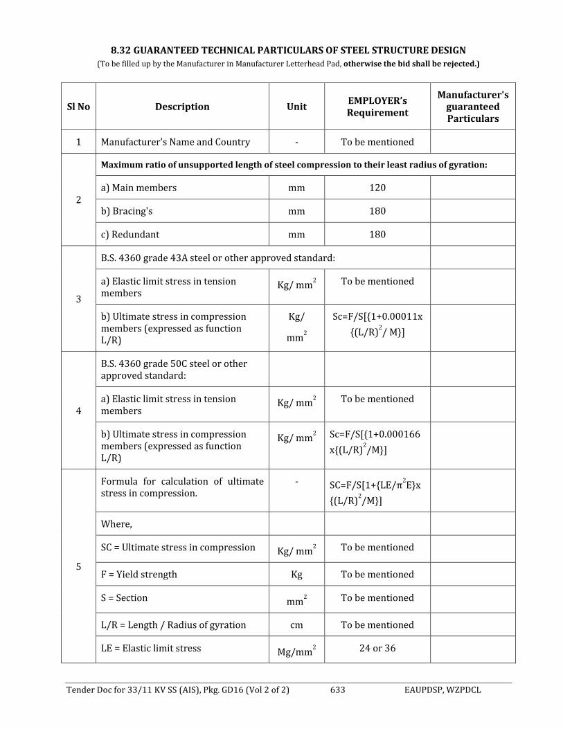
Tender Doc for 33/11 KV SS (AIS), Pkg. GD16 (Vol 2 of 2) 633 EAUPDSP, WZPDCL
8.32 GUARANTEED TECHNICAL PARTICULARS OF STEEL STRUCTURE DESIGN
(To be filled up by the Manufacturer in Manufacturer Letterhead Pad, otherwise the bid shall be rejected.)
Sl No Description Unit EMPLOYER’s Requirement
Manufacturer's guaranteed Particulars
1 Manufacturer's Name and Country - To be mentioned
2
Maximum ratio of unsupported length of steel compression to their least radius of gyration:
a) Main members mm 120
b) Bracing's mm 180
c) Redundant mm 180
3
B.S. 4360 grade 43A steel or other approved standard:
a) Elastic limit stress in tension members
Kg/ mm2 To be mentioned
b) Ultimate stress in compression members (expressed as function L/R)
Kg/
mm2
Sc=F/S[1+0.00011x
(L/R)2/ M]
4
B.S. 4360 grade 50C steel or other approved standard:
a) Elastic limit stress in tension members
Kg/ mm2 To be mentioned
b) Ultimate stress in compression members (expressed as function L/R)
Kg/ mm2 Sc=F/S[1+0.000166
x(L/R)2/M]
5
Formula for calculation of ultimate stress in compression.
- SC=F/S[1+LE/π2Ex
(L/R)2/M]
Where,
SC = Ultimate stress in compression Kg/ mm2 To be mentioned
F = Yield strength Kg To be mentioned
S = Section mm2 To be mentioned
L/R = Length / Radius of gyration cm To be mentioned
LE = Elastic limit stress Mg/mm2 24 or 36

Tender Doc for 33/11 KV SS (AIS), Pkg. GD16 (Vol 2 of 2) 634 EAUPDSP, WZPDCL
Sl No Description Unit EMPLOYER’s Requirement
Manufacturer's guaranteed Particulars
E = Elasticity module Kg/mm2 22000
M = Rigidity Coefficient at each end - To be mentioned
M=1 with only one bolt at each end of member
- To be mentioned
M=2 with two bolts at each end of a member
- To be mentioned
M=4 if L/R between 110 and 130 - To be mentioned
M=3 if L/R over to 130 - To be mentioned
6 Minimum size of member mm 45 x 45 x --
7 Weight of each Column Kg To be mentioned
8 Weight of each Girder Kg To be mentioned
9 Total weight Kg To be mentioned
Seal & signature of Tenderer Seal & signature of Manufacturer

Tender Doc for 33/11 KV SS (AIS), Pkg. GD16 (Vol 2 of 2) 635 EAUPDSP, WZPDCL
8.33 GUARANTEED TECHNICAL PARTICULARS FOR ACSR MARTIN
(To be filled up by the Manufacturer in Manufacturer Letterhead Pad, otherwise the bid shall be rejected.) Sl. No
Description Unit Purchaser’s Requirement
Manufacturer’s Particulars
1 Name of the Item ACSR MARTIN 2 Name of the Manufacturer Shall be mentioned 3 Address of the Manufacturer Shall be mentioned 4 Standard Performance Design and
Testing shall be in accordance to the BS, IEC, ASTM, BDS or equivalent International standards.
5 Installation Overhead 6 Type Stranded 7 Material Hard drawn Aluminium
steel reinforced
8 Overall diameter mm 36.17 9 Nominal cross-sectional area of
conductor mm2 772.10
10 Number/diameter of Aluminium Strand
No./mm 54/4.02
11 Nominal Aluminium cross sectional area
mm2 685.40
12 Number/diameter of Steel Strand No./mm 19/2.41 13 Nominal Steel cross sectional area mm2 86.70 14 Weight of conductor Kg/KM 2590 15 Drum wound length M 500 16 Net weight Kg Shall be mentioned 17 Gross weight Kg Shall be mentioned 18 Maximum DC Resistance of Conductor
at 20 °C /KM 0.0425
19 Minimum breaking Load of Conductor Kg min 11400 20 Maximum working tension of
conductor KN Shall be mentioned
21 Current rating at 35ºC rise over 40ºC ambient temperature (75ºC)
Amps. Shall be mentioned
22 Practical (final) modulus of elasticity hbar 7700 23 Co-efficient of linear expansion /ºC shall be mentioned 24 Aluminum to Steel Ratio Shall be mentioned 25 Lay length for Outermost Layer of
Aluminium mm Shall be mentioned
26 Lay direction for Outermost Layer of Aluminium
Right hand
27 Lay ratio for Outermost Layer of Aluminium
10-14
28 Treated Wooden Drum Standard AWPA C1 – 82, C2 –83, C16 –82, P5 –83.
Seal and Signature of the manufacturer:
Seal and Signature of the Tenderer:

Tender Doc for 33/11 KV SS (AIS), Pkg. GD16 (Vol 2 of 2) 636 EAUPDSP, WZPDCL
8.34 GUARANTEED TECHNICAL PARTICULARS FOR ACSR GROSBEAK
(To be filled up by the Manufacturer in Manufacturer Letterhead Pad, otherwise the bid shall be rejected.)
Sl. No
Description Unit Purchaser’s Requirement Manufacturer’s Particulars
1 Name of the Item ACSR GROSBEAK 2 Name of the Manufacturer Shall be mentioned 3 Address of the Manufacturer Shall be mentioned 4 Standard Performance Design and
Testing shall be in accordance to the BS, IEC, ASTM, BDS or equivalent International standards.
5 Installation Overhead 6 Type Stranded 7 Material Hard drawn Aluminum steel
reinforced
8 Overall diameter mm 25.15 9 Nominal cross sectional area of
conductor mm2 374.70
10 Number/diameter of Aluminum Strand
No./mm 26/3.97
11 Nominal Aluminum cross sectional area
mm2 321.68
12 Number/diameter of Steel Strand No./mm 7/3.09 13 Nominal Steel cross sectional area mm2 53.02 14 Weight of conductor Kg/KM 1304 15 Drum wound length M 500 16 Net weight Kg Shall be mentioned 17 Gross weight Kg Shall be mentioned 18 Maximum DC Resistance of Conductor
at 20 °C /KM 0.0900
19 Minimum breaking Load of Conductor Kg 11400 20 Maximum working tension of
conductor KN Shall be mentioned
21 Current rating at 35ºC rise over 40ºC ambient temperature (75ºC)
Amps. 538 (min)
22 Practical (final) modulus of elasticity hbar 7700 23 Co-efficient of linear expansion /ºC 18.9 x 10⁻⁶ 24 Aluminum to Steel Ratio Shall be mentioned 25 Lay length for Outermost Layer of
Aluminum mm Shall be mentioned
26 Lay direction for Outermost Layer of Aluminum
Right hand
27 Lay ratio for Outermost Layer of Aluminum
10-14
28 Treated Wooden Drum Standard AWPA C1 – 82, C2 –83, C16 –82, P5 –83.
Seal and Signature of the manufacturer: Seal and Signature of the Tenderer:

Tender Doc for 33/11 KV SS (AIS), Pkg. GD16 (Vol 2 of 2) 637 EAUPDSP, WZPDCL
8.35 GUARANTEED TECHNICAL PARTICULARS FOR H-TYPE CONNECTOR
(To be filled up by the Manufacturer in Manufacturer Letterhead Pad, otherwise the bid shall be rejected.)
Sl. No.
Description Purchaser’s Requirement Manufacturer’s
Particulars Compatible for ACSR MARTIN to ACSR MARTIN 1. Name & Address of the
Manufacturer Shall be mentioned
2. Manufacturer’s Code No. Shall be mentioned 3. Applicable Standard Design, Testing & Performance
shall be in accordance to BS, IEC, BDS, ANSI, ASTM or equivalent international standards.
4. Installation Outdoor and shall be installed for the above-mentioned conductor.
5. Type H-Type 6. Material Aluminum 7. Minimum Continuous Current
rating at 35ºC rise over 40ºC ambient temperature (75ºC)
Shall be mentioned (As per current rating conductor)
8. Length Shall be mentioned 9. Weight of 100 nos. in Kg Shall be mentioned
Seal and Signature of the manufacturer: Seal and Signature of the Tenderer:

Tender Doc for 33/11 KV SS (AIS), Pkg. GD16 (Vol 2 of 2) 638 EAUPDSP, WZPDCL
8.36 GUARANTEED TECHNICAL PARTICULARS FOR H-TYPE CONNECTOR
(To be filled up by the Manufacturer in Manufacturer Letterhead Pad, otherwise the bid shall be rejected.)
Sl. No.
Description Purchaser’s Requirement Manufacturer’s
Particulars Compatible for ACSR GROSBEAK to ACSR GROSBEAK 1. Name & Address of the
Manufacturer Shall be mentioned
2. Manufacturer’s Code No. Shall be mentioned 3. Applicable Standard Design, Testing & Performance
shall be in accordance to BS, IEC, BDS, ANSI, ASTM or equivalent international standards.
4. Installation Outdoor and shall be installed for the above-mentioned conductor.
5. Type H-Type 6. Material Aluminum 7. Minimum Continuous Current
rating at 35ºC rise over 40ºC ambient temperature (75ºC)
Shall be mentioned (As per current rating conductor)
8. Length Shall be mentioned 9. Weight of 100 nos. in Kg Shall be mentioned
Seal and Signature of the manufacturer: Seal and Signature of the Tenderer:

Tender Doc for 33/11 KV SS (AIS), Pkg. GD16 (Vol 2 of 2) 639 EAUPDSP, WZPDCL
8.37 :GUARANTEED TECHNICAL PARTICULARS FOR GUY/EARTH WIRE.
(To be filled up by the Manufacturer in Manufacturer Letterhead Pad, otherwise the bid shall be rejected.)
Sl. No.
Description Unit Purchaser's
Requirement Manufacturer’s
Particulars 1 Name of the Item Guy/Earth Wire 2 Name &v Address of the
Manufacturer Shall be mentioned
3 Manufacturer's Code No. Shall be mentioned 4 Standard Performance Design
and Testing shall be in accordance to the BS, BDS or equivalent International standards.
5 Installation Overhead/Stay 6 Type Stranded, Solid and
Bare
7 Material High Strength Steel 8 Overall diameter Mm 9.50 9 Number/diameter of each strand No./mm 7/3.15 10 Nominal cross-sectional area of
conductors mm2 54.53
11 Weight of Guy Wire Kg/KM 430 12 Ultimate Tensile Strength
KN 62.75
13 Galvanization As per ASTM B498-74, Class-A
14 Modulus of Elasticity
Kg/mm2 19.7 x 10³
15 Coefficient of linear expansion /ºC 11.3 x 10⁻⁶ 16 Drum wound length M 1500 17 Net weight Kg Shall be mentioned 18 Gross weight Kg Shall be mentioned 19 Lay length Mm Shall be mentioned 20 Lay direction Right hand 21 Lay ratio 13-18 22 Treated Wooden Drum Standard AWPA C1 – 82, C2 –83,
C16 –82, P5 –83.
Seal and Signature of the manufacturer: Seal and Signature of the Tenderer:

Tender Doc for 33/11 KV SS (AIS), Pkg. GD16 (Vol 2 of 2) 640 EAUPDSP, WZPDCL
8.38 GUARANTEED TECHNICAL PARTICULARS FOR PG CLAMP (MARTIN TO MARTIN)
(To be filled up by the Manufacturer in Manufacturer Letterhead Pad, otherwise the bid shall be rejected.)
Sl. No.
Description Purchaser’s Requirement Manufacturer’s
Particulars
Compatible for ACSR MARTIN to ACSR MARTIN
1. Name & Address of the Manufacturer
Shall be mentioned
2. Manufacturer’s Code No. Shall be mentioned
3. Applicable Standard Design, Testing & Performance shall be in accordance to BS, IEC, BDS, ANSI, ASTM or equivalent international standards.
4. Installation Outdoor and shall be installed for the above-mentioned conductor.
5. Type Bolted Type
6. Material Aluminum Alloy
7. Minimum Continuous Current rating at 35ºC rise over 40ºC ambient temperature (75ºC)
Shall be mentioned (As per current rating conductor)
8. Dimension Shall be mentioned
9. Weight of 100 nos. in Kg Shall be mentioned
Seal and Signature of the manufacturer: Seal and Signature of the Tenderer:

Tender Doc for 33/11 KV SS (AIS), Pkg. GD16 (Vol 2 of 2) 641 EAUPDSP, WZPDCL
8.39 GUARANTEED TECHNICAL PARTICULARS FOR PG CLAMP (GGROSBEAK TO GROSBEAK)
(To be filled up by the Manufacturer in Manufacturer Letterhead Pad, otherwise the bid shall be rejected.)
Sl. No.
Description Purchaser’s Requirement Manufacturer’s
Particulars Compatible for ACSR GROSBEAK to ACSR GROSBEAK 1. Name & Address of the
Manufacturer Shall be mentioned
2. Manufacturer’s Code No. Shall be mentioned 3. Applicable Standard Design, Testing & Performance
shall be in accordance to BS, IEC, BDS, ANSI, ASTM or equivalent international standards.
4. Installation Outdoor and shall be installed for the above-mentioned conductor.
5. Type Bolted Type 6. Material Aluminum Alloy 7. Minimum Continuous Current
rating at 35ºC rise over 40ºC ambient temperature (75ºC)
Shall be mentioned (As per current rating conductor)
8. Dimension Shall be mentioned 9. Weight of 100 nos. in Kg Shall be mentioned
Seal and Signature of the manufacturer: Seal and Signature of the Tenderer:

Tender Doc for 33/11 KV SS (AIS), Pkg. GD16 (Vol 2 of 2) 642 EAUPDSP, WZPDCL
8.40 GUARANTEED TECHNICAL PARTICULARS AND GUARANTEES OF 33 KV BUS BAR & JUMPER
(To be filled up by the Manufacturer in Manufacturer Letterhead Pad, otherwise the bid shall be rejected.)
Sl. No. Description Unit WZPDCL’s
Requirement
Manufacturer's guaranteed Particulars
1 Manufacturer’s Name and country - To be mentioned 2 Material (conductor) a) Bus bars - ACSR MARTIN b) Jumper/ connections - MATRTIN/ HAWK/
GROSBEAK
3 Overall diameter mm To be mentioned 4 Nominal cross section mm2 To be mentioned 5 Cross section and make –up - To be mentioned 6 Maximum rated current A 1250 7 Maximum working tension of main
connections Kg/m2 To be mentioned
8 DC Resistance of conductors per 1000 meters at 20 0C
Ohms To be mentioned
9 Tensile breaking stress of material N/ mm2 To be mentioned 10 Maximum permissible span length m To be mentioned 11 Maximum sag under own weight of
maximum span mm To be mentioned
Seal & Signature of the Manufacturer Seal & Signature of the Tenderer

Tender Doc for 33/11 KV SS (AIS), Pkg. GD16 (Vol 2 of 2) 643 EAUPDSP, WZPDCL
8.41 GUARANTEED TECHNICAL PARTICULARS AND GUARANTEES OF SHIELD WIRE, EARTHING GRID AND EARTHING ELECTRODE
(To be filled up by the Manufacturer in Manufacturer Letterhead Pad, otherwise the bid shall be rejected.)
Sl. No.
Description Unit WZPDCL’s
Requirement
Manufacturer's guaranteed Particulars
A. SHIELD WIRES 1 Manufacturer’s name & country - To be mentioned 2 Material - High Strength
Steel
3 Grade of Steel Kg 60000 4 Nos. of Strand Nos. 7 5 Diameter of each strand mm 3.05 6 Overall diameter mm 9.525 7 Nominal cross -section mm2 35 8 Weight per km length Kg 407 9 Maximum rated current (3 seconds) A To be mentioned 10 Maximum working tension of main connection Kg/m2 To be mentioned 11 Resistance of conductors per 1000 meters at
20 c ohms To be mentioned
12 Rated Ultimate Tensile Strength Kg/mm2 4900 13 Maximum permissible span length m To be mentioned 14 Maximum sag under own weight of maximum
span mm To be mentioned
15 Co-efficient of liner expansion cm/ 0C. To be mentioned 16 Class of Zinc Coating - Class-A 17 Galvanization - As per BS-729 OR
ASTM A-153
B. EARTHING GRID 1 Manufacturer’s name & country - To be mentioned 2 Material - Copper 3 Overall diameter mm To be mentioned 4 Nominal cross -section a) Interconnecting the earth electrodes mm2 To be mentioned b) Connecting equipment to mesh mm2 To be mentioned 6 Area of each earthing grid m x m To be mentioned 7 Depth of bedding of conductor mm To be mentioned 8 Maximum earth fault current for 3 sec. KA 25 9 Resistance of conductors per 1000 meters at 20 Ohms To be mentioned
C. EARTHING ELECTRODES 1 Manufacturer’s name & country - To be mentioned 2 Material - Copper 3 Dimensions:
a) Dia b) Length
mm m
16 4
4 Number of electrodes per group - As per schedule 5 Number of earthing points per substation - To be mentioned
6 Calculated resistance of combined earth grid and points
ohm Less than one (0.5)
Seal & Signature of the Manufacturer
Seal & Signature of the Tenderer
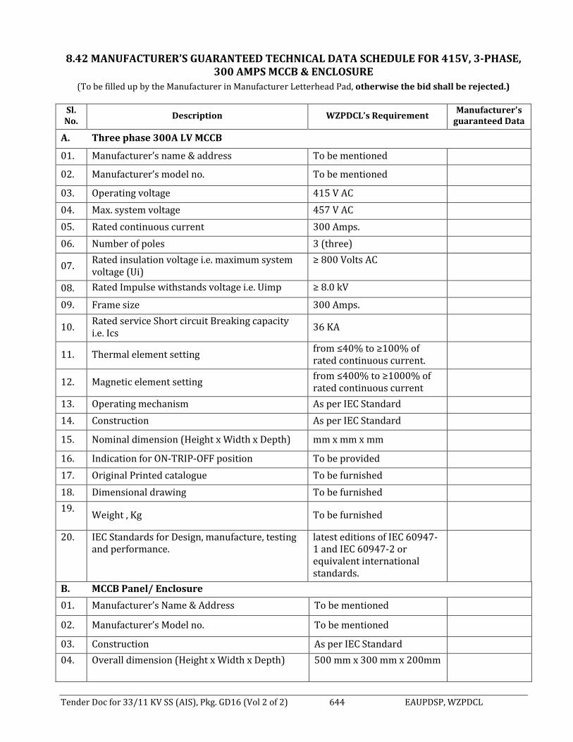
Tender Doc for 33/11 KV SS (AIS), Pkg. GD16 (Vol 2 of 2) 644 EAUPDSP, WZPDCL
8.42 MANUFACTURER’S GUARANTEED TECHNICAL DATA SCHEDULE FOR 415V, 3-PHASE, 300 AMPS MCCB & ENCLOSURE
(To be filled up by the Manufacturer in Manufacturer Letterhead Pad, otherwise the bid shall be rejected.)
Sl. No.
Description WZPDCL’s Requirement Manufacturer's
guaranteed Data
A. Three phase 300A LV MCCB
01. Manufacturer’s name & address To be mentioned
02. Manufacturer’s model no. To be mentioned
03. Operating voltage 415 V AC
04. Max. system voltage 457 V AC
05. Rated continuous current 300 Amps.
06. Number of poles 3 (three)
07. Rated insulation voltage i.e. maximum system voltage (Ui)
≥ 800 Volts AC
08. Rated Impulse withstands voltage i.e. Uimp ≥ 8.0 kV
09. Frame size 300 Amps.
10. Rated service Short circuit Breaking capacity i.e. Ics
36 KA
11. Thermal element setting from ≤40% to ≥100% of rated continuous current.
12. Magnetic element setting from ≤400% to ≥1000% of rated continuous current
13. Operating mechanism As per IEC Standard
14. Construction As per IEC Standard
15. Nominal dimension (Height x Width x Depth) mm x mm x mm
16. Indication for ON-TRIP-OFF position To be provided
17. Original Printed catalogue To be furnished
18. Dimensional drawing To be furnished
19. Weight , Kg To be furnished
20. IEC Standards for Design, manufacture, testing and performance.
latest editions of IEC 60947-1 and IEC 60947-2 or equivalent international standards.
B. MCCB Panel/ Enclosure
01. Manufacturer’s Name & Address To be mentioned
02. Manufacturer’s Model no. To be mentioned
03. Construction As per IEC Standard
04. Overall dimension (Height x Width x Depth) 500 mm x 300 mm x 200mm

Tender Doc for 33/11 KV SS (AIS), Pkg. GD16 (Vol 2 of 2) 645 EAUPDSP, WZPDCL
Sl. No.
Description WZPDCL’s Requirement Manufacturer's
guaranteed Data
05. Thickness (minimum) 1.63 mm
06. Material of the box Galvanized steel sheet of min 1.63 mm thick.
07. Necessary fixing channels with adjustable hole including nuts, bolts etc.
Shall be provided
08. Standard of galvanization Latest revision of ASTM A90/ BS EN ISO 1461:2009 standard.
09. Dimensional drawing To be furnished
Seal & Signature of the Manufacturer Seal & Signature of the Tenderer

Tender Doc for 33/11 KV SS (AIS), Pkg. GD16 (Vol 2 of 2) 646 EAUPDSP, WZPDCL
8.43 GUARANTEED TECHNICAL PARTICULARS AND GUARANTEES OF LED FLOOD LIGHT
(To be filled up by the Manufacturer in Manufacturer Letterhead Pad, otherwise the bid shall be rejected.)
Sl. No.
Description Unit WZPDCL's
Requirement
Manufacturer's guaranteed Particulars
1 Manufacturer’s Name & country of origin
- To be mentioned
2 Manufacturer’s model No. - To be mentioned
3 Input Voltage V 220
4 Operating Voltage V 180-240
5 Rated Wattage W 50
6 Efficacy lu/W 100 7 Driver Efficiency Min 90% 8 Life Span Hrs 50000 Operating temperature -5 to 50degree C
9 color temperature K 5000-6000
10 Housing - in two pieces (upper and lower housings) Die cast
aluminum housing
11 Electrical and gear compartment Integral Inverter Electronic
12 Protection Degree IP65
13 painting RAL 7035
14 Frequency Hz 50
15 Front Glass F - Flat glass
16 Net Wight Kg To be mentioned
Seal & Signature of the Manufacturer Seal & Signature of the Tenderer

Tender Doc for 33/11 KV SS (AIS), Pkg. GD16 (Vol 2 of 2) 647 EAUPDSP, WZPDCL
8.44 GUARANTEED TECHNICAL PARTICULARS AND GUARANTEES OF LED SIGN BOARD (ELECTRONIC)
(To be filled up by the Manufacturer in Manufacturer Letterhead Pad, otherwise the bid shall be rejected.)
Sl No Description WZPDCL’s
requirement
Tenderers Guaranteed particulars
1 Pixel pitch P4/ P6
2 LED configuration SMD
3 LED density Minimum 8500
LED/m²
4 Brightness 6,500 nits (calibrated)
5 Color Processing 16 bit/color
6 Colors 281 trillion
7 Hor. viewing angle -70°/+70°
8 Vert. viewing angle -35°/+10°
9 Power consumption (typical) Max 300 W/m²
10 Heat dissipation (typical) 784 BTU/hr/m²
11 Operational temperature -20°/+50°C
12 Ruggedness IP65 (front)
13 Dimensions (HxWxD) 7 x 5 feet
14 Module surface Minimum 1 m²
15 Weight / Tile To be mentioned
16 Features: Audio, Video, Elkbone frame, Ethernet, HDMI, USB, VGA with all necessary configuration software
Yes
17 Certifications CE, ETL, FCC Class A, CEBEC, RohS
Seal & Signature of the Manufacturer Seal & Signature of the Tenderer

Tender Doc for 33/11 KV SS (AIS), Pkg. GD16 (Vol 2 of 2) 648 EAUPDSP, WZPDCL
8.45 TECHNICAL REQUIREMENT & GUARANTEE SCHEDULE FOR SUBSTATION AUTOMATION SYSTEM
(To be filled up by the Manufacturer in Manufacturer Letterhead Pad, otherwise the bid shall be rejected.)
Sl. No DESCRIPTION WZPDCL
REQUIREMENT
Manufacturer's guaranteed Particulars
1. Name of the Manufacturer/Developer Country of Origin EU/USA/CANADA/Japan
2. General Requirement: Standards to be complied with Substation Automation system
Communication protocol at all levels IEC 61850.Fully
complying with the standard.
Temperature range (min/max) Computer 0° to 50° C
Relative humidity 20 to 90 % non-
condensing
Base of Station HMI Active X
System performance and inter-operability test among ABB, Siemens, Alstom, Schneider, GE and SELIEDs done in the system verification center.
Yes
Control IEDs and protection IEDs are from same manufacturer
Yes
Intelligent Electronic devices (IED’s)
Manufacturer’s name & address Shall be mentioned
Serial communication interface included? YES
Protection & Control IED’s connected same bus? Yes (IEC61850)
Self-monitoring To be provided
Display of measured values To be provided
Remote parameterization To be provided
Disturbance record upload & analysis To be provided
Availability Calculation shall be furnished for each equipment & as well as for the entire system
To be provided with Bid.
3 Detailed Requirements:
Number of years of proven field experience of Offered system. (Note: Proof of experience should be furnished. The components used in the offered system and those with field experience should be the same)
5Yrs.
Model of the Substation Automation System Shall be mentioned Name and Address of the manufacturer Shall be mentioned Name of the Manufacturer/Developer Shall be mentioned Country of Origin EU/USA/CANADA/Japan
The Automation Panel shall be from the origin of the manufacturer of the system
Yes
Engineering and Assembling of t h e substation automation system shall be from the origin of the system.
Yes
Design life of Substation Automation System ≥ 20 Yrs

Tender Doc for 33/11 KV SS (AIS), Pkg. GD16 (Vol 2 of 2) 649 EAUPDSP, WZPDCL
Sl. No DESCRIPTION WZPDCL
REQUIREMENT
Manufacturer's guaranteed Particulars
Manufacturers quality assurance system ISO 9001/ 9002 or
equivalent
Dimensions of cubicle
Width mm
Depth mm
Height mm
Floor load N/sq. m max. 600 4 Station Level Equipment: Station Computer Industrial PC MTBF (Mean time between Failures) Hrs MTTR (Mean time to repair) Hrs
Dual Station Computers Provided in redundant hot standby configuration
YES
Hot standby takeover time Seconds
Number of years of proven field experience of offered software
5 Yrs
Operating System Windows All standard picture as per Tspec included in HMI To be provided Process Status Display & Command Procedures To be provided Event processing as per Tspec To be provided Alarm processing as per Tspec To be provided Reports as per Tspec To be provided Trend Display as per Tspec To be provided User Authority levels as per spec To be provided System supervision & monitoring as per Tspec To be provided Automatic sequence control as per Tspec To be provided
High quality SCD file complete with ICD files & station topology
To be provided
5 Gateway to Central Control Room (2 Nos) Name of manufacturer & Country of origin To be provided Model no. To be provided
Number of years of proven field experience of offered unit
5Yrs
Insulation tests IEC60255-5
Fast disturbance tests IEC 61000-4-4, Calss4
Industrial environment EN50081-2, Class A
Industrial grade hardware with no moving parts (PC-based gateway is not accepted)
To be provided
Design life of offered equipment 20Yrs
Redundant communication channel To be provided
Redundant CPU To be provided
Redundant DC/DC Supply To be provided
MTBF (Mean time between Failures) Hrs
MTTR (Mean time to repair) Hrs

Tender Doc for 33/11 KV SS (AIS), Pkg. GD16 (Vol 2 of 2) 650 EAUPDSP, WZPDCL
Sl. No DESCRIPTION WZPDCL
REQUIREMENT
Manufacturer's guaranteed Particulars
Manufacturer’s Catalogue To be provided
6 Station Bus:
Physical Medium Armoured Glass fiber
optic
7 Inter bay Bus
Physical Medium Armoured Glass fiber
optic
8 Printer Server MTBF Hrs
9 Event Printer MTBF Hrs
10 Hard Copy Colour Printer MTBF Hrs
11 Master Clock – GPS (Global Positioning System) Receiver: Name of the manufacturer & Country of origin Shall be mentioned Manufacturer’ s address Shall be mentioned Model Shall be mentioned MTBF Hrs
12 Bay Control Unit – HV/ IED; Separate Bay controller unit shall be provided for each
bay/feeder, which will be the part of GIS panel. Manufacturer’s name & address Shall be mentioned Type or Model Shall be mentioned Country of Manufacture Shall be mentioned
Number of years of proven field experience of offered unit
5 Yrs.
Separate Bay-controller unit provided for each bay & feeder
Yes
Type of Bay-controller offered HV/MV HV
Select Before Operate with Open Execute & Close Execute
Yes
Single bit dependence No
Interlocking, bay & station wide Synchro check function
Yes
Maximum Voltage difference Specify range
Maximum Frequency difference Specify range
Maximum Phase difference Specify range
Double command blocking Yes
Independent settable parameter groups Yes
Local Display Unit 4
Sequence of event recorder To be provided
Events 256
Time resolution 1ms
Disturbance recorder function YES
Comprehensive self-supervision YES

Tender Doc for 33/11 KV SS (AIS), Pkg. GD16 (Vol 2 of 2) 651 EAUPDSP, WZPDCL
Sl. No DESCRIPTION WZPDCL
REQUIREMENT
Manufacturer's guaranteed Particulars
Battery free backup of events and disturbance records
YES
Insulation tests IEC60255-5
Fast disturbance tests IEC61000-4-4, Class 4
MTBF Hrs.
MTTR Hrs.
Temperature range: IED’s
Operation -10 to +50
Transport and storage -10 to +50
Relative humidity:
Operating max./min 93%
Transport and Storage 93%
13 Backup Control Mimic – HV Control functionality: Control of breaker as well as all isolators/earthing To be provided
Switch (Control functionality should not be affected if bay-controller fails) Key-Locked
To be provided
Interlock override function To be provided
Separate backup control mimic provided for each bay & feeder
To be provided
14 Bay Control Unit/ IED – MV; Separate Bay controller unit shall be provided for each bay/feeder, which will be the part of GIS panel.
Manufacturer’s name & address Shall be mentioned Type or Model Shall be mentioned Country of Manufacture Shall be mentioned
Number of years of proven field experience of offered unit
5 Yrs.
Separate Bay-controller unit provided for each bay & feeder
Yes
Control functionality implementation in software: To be provided
Select Before Operate with Open Execute & Close Execute
Yes
Interlocking, bay & station wide Synchro check function
Yes
Maximum Voltage difference Specify range
Maximum Frequency difference Specify range
Maximum Phase difference Specify range
Local Display Unit To be provided
Sequence of event recorder To be provided
Events Specify
Time resolution 1ms
Disturbance recorder function To be provided

Tender Doc for 33/11 KV SS (AIS), Pkg. GD16 (Vol 2 of 2) 652 EAUPDSP, WZPDCL
Sl. No DESCRIPTION WZPDCL
REQUIREMENT
Manufacturer's guaranteed Particulars
Comprehensive self-supervision To be provided
Supervision Insulation tests IEC60255-5
Fast disturbance tests IEC61000-4-4, Class 4
MTBF Hrs.
MTTR Hrs.
Temperature range: IED’s
Operation -10 to +50
Transport and storage -10 to +50
Relative humidity:
Operating max./min 93%
Transport and Storage 93%
15 Backup Control Mimic – MV Control functionality:
Control of breaker as well as all isolators /earthing switches Separate backup control mimic provided for each bay & feeder
To be provided
16 Ethernet Switch Name of manufacturer &. address Shall be mentioned Model number Shall be mentioned
Type Industrial Grade,
rackable 19”-24 ports (min.)
Redundant Power supply To be provided 17. Operator Work Station (OWS)
Brand Any International
reputed brand.
Model To be mentioned Type Industrial PC
Country of Manufacture USA/ UK/ EU /Japan/
Canada
Processor GHz Intel core i7 10th
generation or latest
Clock Speed GHz 3.0 GHz (min), 8 MB Cache Memory (min)
Bus Speed MHz Min. 1600 MHz or higher
RAM GB 8 GB, Expandable to 16
GB (mini.)
HDD GB 2 x 1 TB SSD (RAID with
NVMe)
Mouse Same Brand USB Scroll
Optical Mouse
Keyboard Same brand USB
Keyboard
Monitor inch Same brand LED 24", 1920x1080, Full HD

Tender Doc for 33/11 KV SS (AIS), Pkg. GD16 (Vol 2 of 2) 653 EAUPDSP, WZPDCL
Sl. No DESCRIPTION WZPDCL
REQUIREMENT
Manufacturer's guaranteed Particulars
Monitor
OS Support Windows 10 Professional
or latest
OS License windows with
recovery kit
Software Licensed Anti-Virus
Software
18 Engineer Work Station (EWS)
Brand Any International
reputed brand.
Model To be mentioned
Type Industrial PC
Country of Origin USA/ UK/ EU/ Japan/
Canada
Processor GHz Intel Core i5 Processor,
10th generation or latest
Clock Speed GHz 3.0 GHz (min), 8 MB L3
Cache Memory (min)
Bus Speed MHz Min. 1600 MHz or higher
RAM GB (2x4 GB) 1 DIMM DDR4
HDD GB Min. 512 GB SSD NVMe
Mouse Same Brand Wireless Scroll Optical Mouse
Keyboard Integrated standard
Keyboard
Monitor inch 15.6", Full HD, True Life
Display
Battery 6 cell lithium ion battery
Battery Backup 6 hours or higher with A/
C Adapter
OS Support Windows 10 professional
or latest
OS License windows with
recovery kit
Software Licensed Anti-Virus
Software
19. Laser Color Printer
Brand Any International
reputed brand.
Model To be mentioned
Country of Origin USA/ UK/ EU/ Japan/
Canada
Toner type Toner and associated
drum unit in single case, No starter toner.
Resolution dpi 1200 x 1200 dpi
(Minimum)
Printing Speed ppm 62-Page-per Minute

Tender Doc for 33/11 KV SS (AIS), Pkg. GD16 (Vol 2 of 2) 654 EAUPDSP, WZPDCL
Sl. No DESCRIPTION WZPDCL
REQUIREMENT
Manufacturer's guaranteed Particulars
(Letter), 35 PPM (A4) (min.)
First Page Print Out secon
d As fast as 8 seconds
Memory MB 256 MB (Minimum) Expandable to 1 GB
Trays
100 sheet multi-purpose input tray, 2 x 500 sheet input tray 50-sheet face
up output tray, 250-sheet face down output tray
Media Sizes Letter, Legal, A4, A5, B5
and custom sizes
Media Types
Paper (Plain, Preprinted, Letterhead, Bond, Color,
Recycled, Rough), Transparencies, Labels
20 Event Printer
Brand Any International
reputed brand.
Model To be mentioned
Country of Origin USA/ UK/ EU/ Japan/
Canada
Print Method PIN 9 Pin Serial Impact Dot
Matrix.
Print Speed LPS Min. 6.0 LPS (30
Columns: 16 CPI).
Data Buffer KB 4KB.
Inked Ribbon ERC-38(Black/Red).
Interface USB Interface, Bi-
directional parallel.
21 System Performance: Exchange of display (First reaction) <2S Presentation of a binary change in the Process display <1S Presentation of an analogue change in the process display <1S From order to process output <1S From order to updated of display <1S
22 UPS
Brand Any International
reputed brand.
Model To be mentioned
Country of Origin USA/ UK/ EU/ Japan/
Canada
Capacity VA Backup 2 hours Battery capacity To be mentioned
23 Protocol Converter / IO module, if required Brand To be mentioned
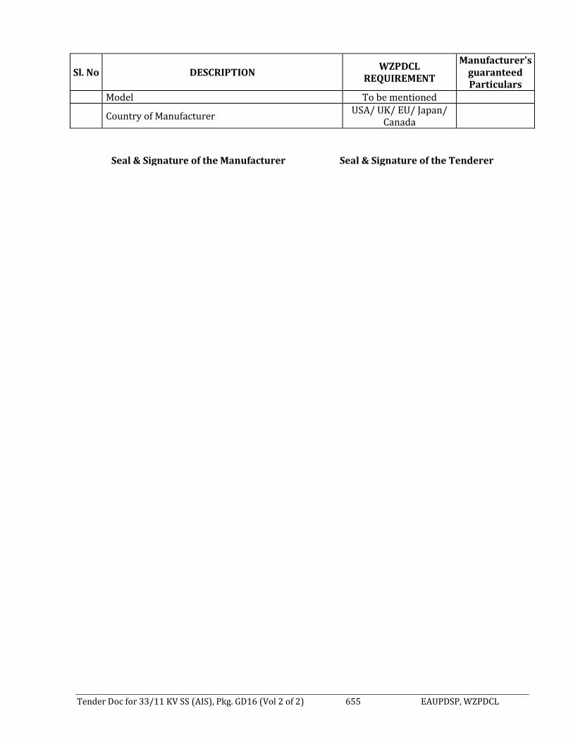
Tender Doc for 33/11 KV SS (AIS), Pkg. GD16 (Vol 2 of 2) 655 EAUPDSP, WZPDCL
Sl. No DESCRIPTION WZPDCL
REQUIREMENT
Manufacturer's guaranteed Particulars
Model To be mentioned
Country of Manufacturer USA/ UK/ EU/ Japan/
Canada
Seal & Signature of the Manufacturer Seal & Signature of the Tenderer

Tender Doc for 33/11 KV SS (AIS), Pkg. GD16 (Vol 2 of 2) 656 EAUPDSP, WZPDCL
8.46 GUARANTEED TECHNICAL PARTICULARS FOR DESKTOP COMPUTER (To be filled up by the Manufacturer in Manufacturer Letterhead Pad, otherwise the bid shall be rejected)
Sl. No.
Description WZPDCL's
Requirement
Manufacturer's guaranteed Particulars
1 Brand To be mentioned (Any International reputed brand operating in the recognized continental markets for decades.)
2 Model To be mentioned 3 Country of origin North America / EU / Japan 4 Country of
Manufacturer To be mentioned
5 Processor Speed (Clock speed)
3.6 GHz (min)
6 Processor 10th Generation Intel Core i5 Processor, 8MB Cache or higher
7 Storage 1TB SATA HDD 7200 rpm 8 Performance RAM 8GB (8GBx1) DDR4 upgradable up to 64GB DDR4-2400
SDRAM
DIMM 4 Chipset Intel original Q272 chipset
Graphics Card Integrated Intel HD Graphics 630 9 Screen Screen features LED Backlight Color Monitor Screen size 24 inches
10 Connectivity
Audio High Definition Integrated Audio Bays 1 internal 3.5” 2 internal 2.5”, 1 external 5.25” I/O Ports 8 External USB: 4 x 3.0 (2 front/2 rear) and 4 x 2.0 (2
front/2 rear); 1 RJ-45;1 Display Port 1.2; 1 UAJ, 1 Line-out; 1 VGA, 2 low-profile PCIe x16 (one wired as a x4); 2 low-profile PCIe x1; 1 M.2 2230 for optional wireless
11 NIC 10/100/1000 baseT (built in /Integrated) 12 Media
Optical drive Super Multi DVD writer 13 Features
Keyboard USB Entry Business Keyboard (English) Mouse USB Optical Mouse
14 Power Supply 220-240V, 50Hz 15 General
Operating system Windows 10 Pro (Licensed) Warranty International warranty Software a) Windows 10 Pro (Licensed)
b) MS office 2013 Professional (Licensed) Brochure and CDs All brochure, instructions, manual and driver CDs to be
supplied with the product
Connection Cables All necessary power and data connection cables to be supplied along with the product , power cables (3 pin flat)
Seal & Signature of the Manufacturer Seal & Signature of the Tenderer

Tender Doc for 33/11 KV SS (AIS), Pkg. GD16 (Vol 2 of 2) 657 EAUPDSP, WZPDCL
8.47 GUARANTEED TECHNICAL PARTICULARS FOR UPS
(To be filled up by the Manufacturer in Manufacturer Letterhead Pad, otherwise the bid shall be rejected)
Sl. No.
Description WZPDCL's
Requirement
Manufacturer's guaranteed Particulars
1 Brand & Model To be mentioned (Any International Reputed Brand & Model)
2 Capacity 1000 VA
3 Technology Line Interactive 4 Transfer Time <2 ms 5 Input Voltage 140~300 VAC 6 Input Frequency 50/60 Hz± 5% 7 Output Voltage 220 VAC ± 8% 8 Output Frequency 50/60 Hz± 5% 9 Output Wave form AC Mode: Simulated Sine wave
10 Backup time At full load 30 minutes (one computer with monitor)
11 Battery Type Sealed Maintenance free Lead Acid 12 Battery Recharging 8-10 Hours 13 Noise (EMI/RFI) filter Built in 14 Protection Spike, Surge, Blackout, Brownouts, Overload,
Short circuit, Under & Over Voltage, Battery Low & Battery Over charge as per international Safety Standard
15 UPS Warranty 03 (Three) Years Replacement warranty 16 Battery Warranty 01 (one) Year warranty from the date of
commissioning.
Seal & Signature of the Manufacturer Seal & Signature of the Tenderer

Tender Doc for 33/11 KV SS (AIS), Pkg. GD16 (Vol 2 of 2) 658 EAUPDSP, WZPDCL
8.48 GUARANTEED TECHNICAL PARTICULARS FOR NETWORK LASER DUPLEX PRINTER
(To be filled up by the Manufacturer in Manufacturer Letterhead Pad, otherwise the bid shall be rejected)
Description Unit WZPDCL's
Requirement
Manufacturer's guaranteed Particulars
1 Brand To be mentioned (Any International reputed
brand operating in the recognized continental markets for decades.)
2 Model To be mentioned 3 Country of Origin North America / EU / Japan
4 Country of Manufacturer
To be mentioned
5 Toner type Toner and associated drum unit in single case,
No starter toner.
6 Fuser Unit Instant on fuser technology with ceramic heating
elements.
7 Resolution dpi 1200 × 1200 dpi (Minimum) 8 Processor MHz Min. 800 MHz 9 Printing Speed ppm 32-Page-per Minute (Letter), 35 PPM (A4) (min.)
10 First Page Print Out
second
As fast as 8 seconds
11 Memory MB 256 MB (Minimum) Expandable to 1 GB 12 Memory Slots 2 DIMM Slots Minimum
13 Interface Jet direct Fast Ethernet embedded print server,
two open EIO slots, High Speed USB 2.0 Port & Parallel Port (min.)
14 Languages PCL 6, PCL 5e, POST Script 3 emulation 15 Duty Cycle page 2, 75,000 Pages per Month
16 Trays 100 sheet multi-purpose input tray, 2 x 500 sheet
input tray 50-sheet face up output tray, 250-sheet face down output tray
17 Media Sizes Letter, Legal, A4, A5, B5 and custom sizes
18 Media Types Paper ( Plain, Preprinted, Letterhead, Bond,
Color, Recycled, Rough),Transparencies, Labels
19 Power Requirements
220-240 V / 50Hz
20
Client Operating System Supported
Windows XP/7/8/10 Linux etc., server
21
Network Operating System Supported
Via Jet direct print server: Me, NT 4.0, 2000, XP, XP 64-bit, Server 2003, Red Hat Linux 6 and later.
22
Network Protocols Supported
Via Jet direct print server: TCP/IP, HTTP
23 Warranty Period Full 03(Three) years replacement and instant
service warranty. Replacement time maximum 07 (Seven) days.
Seal & Signature of the Manufacturer Seal & Signature of the Tenderer

Tender Doc for 33/11 KV SS (AIS), Pkg. GD16 (Vol 2 of 2) 659 EAUPDSP, WZPDCL
8.49 GUARANTEED TECHNICAL PARTICULARS FOR AIR CONDITIONER (To be filled up by the Manufacturer in Manufacturer Letterhead Pad, otherwise the bid shall be rejected)
SI. No.
Item Description WZPDCL's
Requirement
Manufacturer's guaranteed Particulars
In Door Unit Specification: Floor Ceiling Unit 4 Ton 01 Brand International reputed Brand like General,
Panasonic, Toshiba, Hitachi, Samsung & LG.
02 Model To be Mentioned 03 Country of Origin To be Mentioned
04 Cooling Capacity (Min) 14 kW 48,000 Btu/h
05 Heating Capacity (Min) 15 kW 48,000 Btu/h
06 Air Flow Min 1600 m3/h Min 940 CFM
07 Sound Pressure Level <45 dB 08 Dimension To be Mentioned 09 Net weight To be Mentioned
10 To be Submitted with Tender Document
Original Brochure & Catalogue supporting the model offered by the Tenderer
11 Free Servicing 02 (Two) year from the day of completion of installation testing and commissioning of VRF system.
12 Warranty 02 (Two) Year from the day of installation, testing and commissioning of VRF system inclusive of Parts
Seal & Signature of the Manufacturer Seal & Signature of the Tenderer

Tender Doc for 33/11 KV SS (AIS), Pkg. GD16 (Vol 2 of 2) 660 EAUPDSP, WZPDCL
8.50 GUARANTEED TECHNICAL PARTICULARS OF DIGITAL HIGH VOLTAGE 5 KV INSULATION RESISTANCE TESTER
(To be filled up by the Manufacturer in Manufacturer Letterhead Pad, otherwise the bid shall be rejected.)
Sl. No. Parameters WZPDCL’s Requirement Bidder’s Particulars 1. Name of Manufacturer &
Address To be Mentioned
2. Model To be Mentioned 3. Country of Origin EU/ USA/ UK/ Japan/ Canada 4. Test Voltage (DC V) With fixed ranges of 500V, 1000V,
2.5 KV and 5 KV
5. Insulation Resistance Measuring Ranges (Auto-Range)
0 to 1 TΩ
6. Accuracy ±5% of reading 7. Capacitance measuring range 10nF to 25 µF with accuracy of
±10%
8. Current measuring range ±0.01mA to 3mA with accuracy of ±5%
9. Timer Range 0 to 99 minutes 10. Testing parameters IR, PI, DAR, 11. Guarding 2% error guarding 100Mohm load 12. IP Rating IP65 13. Storage On board storage of measurement
with time stamping up to 100 results or more
14. Dimensions Should be portable 15. Weight (Battery Included) Approx. 10Kg 16. Power Source In Built Rechargeable Battery (Li
ion) with 4 Hrs continuous testing at 5KV with 100 MΩ load and shall be operational on main and battery individually and simultaneously. BATTERY SHALL MEET IEC 62133
17. Accessories Test leads 15 meters each (good insulation) + large clips, software, screened USB Cable.
Seal & Signature of the Manufacturer Seal & Signature of the Tenderer

Tender Doc for 33/11 KV SS (AIS), Pkg. GD16 (Vol 2 of 2) 661 EAUPDSP, WZPDCL
8.51 GUARANTEED TECHNICAL PARTICULARS OF EARTH & SOIL RESISTANCE TESTER
(To be filled up by the Manufacturer in Manufacturer Letterhead Pad, otherwise the bid shall be rejected.)
Sl. No.
Description WZPDCL’s Requirement Bidder’s
Particulars
1. Name of Manufacturer & Address
To be Mentioned
2. Model To be Mentioned
3. Country of Origin EU/ USA/ UK/ Japan/ Canada
4. Earth resistance range and accuracy
0.010 to 19.99kΩ, auto-ranging, 1mΩ resolution and accuracy of ±0.5% ±2 digits
5. Comply with standards BS 7430, IEC 61010, IEC 61326
6. Test frequency 105 to 160Hz reversing d.c. (50Hz
operation default to 128Hz) set in steps of 0.5Hz
7. Test current 50mA max (selectable high and low
levels)
8. Maximum output voltage 50V r.m.s.
9. Maximum interference 40V peak-to-peak (50Hz sinusoidal
nature)
10 Display Alphanumeric LC.D. giving test
information and a large (20mm) 3Yz-digit reading
11. Environmental protection IP54
12. Flash test 3 KVa.c.
13 Fault conditions To withstand 240Va.c. between any two
terminals
14.
Power supply (1) Rechargeable battery, (2) 5hours life continuous use (3) Charging supply required: 200 to 260V 50Hz (4) Charging time: 6hrs max (from completely exhausted), charging current automatically controlled to stop overcharging
15. Weight Approximately 5kg (for ease of field use)
Seal & Signature of the Manufacturer Seal & Signature of the Bidder
Annex-6.4.1:
Drawings (Lay-out & SLD) for Nabagram 33/11 kV 2x10/13.33 MVA AIS Sub-station (New) under GD-16

~
I. " ' K I I -c: I .. I ,, I .... . I
I
SOUTH~NORTH "" - -1 1
.... 99.39m j
.... -
12 ....J 2
.... ....
3
I \___ 3
E ~m~ co ..... c.o
N ....
'<t
E - --
4 ~ 4
l ~
.... -
I I
I 5 I I
__ ..I 5
91.76m ·---I
LEGEND I ---f ·- ' .... I
BOUNDARY WAL L .................... ~ PUCCA ROAD............. ...... ... ...... =
6 RCCROAO ~ 6 KATCHA ROAD .... ... .... .... ......... .... c===:> FENCING............. ........ ...... ... ..... . --BUILDING... .... ..... .. ...... .. .............. rmJ
-Revision I Consultant Engineers Associates Ltd. Sub-station INABAGRAM 33/11 kV , 2X10/1 3.33 MVA AIS SUB-STATION (NEW)
WEST ZONE POWER DISTRIBUTION COMPANY LIMITED ~,.,~ T ITLE Drawing No.
7 Drawn by Md. Abdul Baten
EXPANSION ANO UP-GRADATION OF POWER EXISTING SITE LAYOUT PLAN OF 7
DISTRIBUTION SYSTEM PROJECT Checked by Engr. Rama Nath Roy ~/ v 33/11 kV NABAGRAM SUB-STATION NAB-01
A I ts I c I u I E I f/ G I H I I I j I L. :__J

~
r~~~-.--~----.-~--~-.-----~---,-~--------.-~--~-.-----.-----,-~-rr--------.~----.--~-.- -i
L.
..
r1 SOUTH . NORTH ~ I
t I-
99.3Bm
21 21
l:i1 d
Ir
"' . <l " .
4
<1 ~4 71 .49m A
q ~ r ~. -~ J --~ -~~· f ~ . <l "
" " I'-
E co (")
3
,_.
4
5
El ~l ""I
I
q ki •
"
[] "
I
/
15.00m
Control Building
! E I co ~ m I !(") I E 1...- " co I I <D
] '--'513m N I I . "" IE l 1g ! l..o " I..-_.._~~-~-~~~__.._ I ~
·- 20.oom , • , , , , , , , ~"" •• • • _,, .•
1 '~;- I - 34.77m
42~1m I -- -· ---91 .76m
LEGEND
BOUNDARY WALL ............... .... . PUCCA ROAD.... .. ...................... =
61 RCC ROAD ................................... == TRENCH LINE .... .. .................... i ii II 11 II 11 o FENCING..... ..... .... ......... ............. · o--o-
BUILDING .... ........ ....... ....... .......... u~ff.il I
~
-- I
<D ~ ...-
p.uun I :r I
- ~" 1-
~ 3
141
~-- ·~ f'-0 -
cD N
1 ~
i !
Si
L "J"- I-
51
Revision i-------- -L---------------l consultant Engineers Associates ltd. Sub-station NABAGRAM 33/11 kV, 2X10113.33 MVA AIS SUB-STATION NEW TITLE Drawing No.
WEST ZONE POWER DISTRIBUTION COMPANY LIMITED 7 Drawn by
A
EXPANSION AND UP-GRADATION OF POWER DISTRIBUTION SYSTEM PROJECT
T s: I ~ 1
Checked by
D T
Md. Abdul Baten
Engr. Rama Nath Roy
E I
~~ ~ F ~
PROPOSED SITE LAYOUT PLAN OF 33/1 1 kV NABAGRAM SUB-STATION
I H I I .I
7
NAB-02
I
~

""""" I .
A I R ( ' 11 I .... I I- I r ~ I H I I I .I I .1
NOA:TK
f- + ~ 1500 SOUTH
I 7.50 7.50 I 1500 I Wl
1 Wl WI ~ WI WI L ..J 1 WI WI WI -3000~ 1 1 50
I I Banery Charge<. AC, OC and I Battery Room SCAOA
- ~~-3~~2~~200 T WI
AIS-1 ..... WI WI WI @\ AIS-2 11 " ! 12 1 u 114 I
oso:::J" 0 601--1
2 7 50 AIS-3 - ~300-- 2
AIS-4 I Rest WI WI WI AIS·S
oso::r 351 Room WI ..... -
AIS·6 l @-......._, \ '
3 AIS·7 3 00 D[!] ~:':'lJ 3
15.0o+-- 0 15.00 ]
J 1 D gs 0 0 AIS·S \X"l
..... J ..... (/)
AIS-9 ~
WI \\'I WI ~
AIS-10 C> WI .c ·- ll
4 ~ 4 AIS-11 >
;!! i 50 AIS-12
..... - 100 622 -AIS-13 I 33.W Con:rOI Relay a:>a Metenng iAIS) Panel I
WI \\' I WI 1 <15-l WI jl-191-I 1
5 1 I 1 I 2 I 3 I 4 I 5 I 6 I 7 I 8 I 9 I 1° I
..... .. .. '1 220 oso:r I oao-J-r- 3 04-'-~ 5
I 122 , WI ® "
... \\I I WI - I I I I I I I I I @ I - T T Ground Floor Plan I I I I I I I I I I I I I I I I I I
..... I I I I I I I I I Firs t Floor Plan : : : : : : : : : ~ntrol Building Plan l I I I I I I I I I
II 1111 1.1 2 28 ! Control Building P l~l
n ll 111 2 28 Uttw rt•:-:rto! Ooct $ •.•~ I ,J 6 '""' ~K"<'i>Ol'I Vo'dll'\ .... ..,,. I I 11 11 11111 ,, ~\!Goel•" ))or 1nor 1q ;>1 )01 .:-, .... r , 6
I» Woocl• .. Qoo• 1.0?0fll• · , l'llor·r) I I I o.; lfl>OCIN'H ) t l>,'C !> ... ~< ()o31 0760-flG-"I ~ I) OI 111 5.44 I 5.44
"'' St<t tl Ft;i,--.c, Oo~llP p~.,tl ni•• Cl.\$$ tMrw»,,, I ~10fi:,) I 3·' e•<•6'1 Note : All dimensions are given in meter
W2 Stolt! F1;i~<.1 l'Xvtl~ ?;t ... ~1 T~>Cln~ Wr..OOw 061 «(1°1 OGIG• 1, Note : All dimensions are given in meter
..... -Revision I Sub-station I NABAGRAM 33/11KV, 2X10/1 3.33 MVA AIS SUB-STATIO N (NEW)
WEST ZONE POWER DISTRIBUTION COMPANY LIMITED Consultant Engineers Associates Ltd. Title Drawing No.
7 EXPANSION AND UP-GRADATION OF POWER Drawn By Md. Abdul Baten A.~~ LAYOUT DIAGRAM OF CONTROL BUILDING 7
DISTRIBUTION SYSTEM PROJECT Checked By ~/ (GR.FLOOR & FIRST FLOOR) NAB-03 Engr. Rama Nath Roy
A I B I r. I u F I I'" J l ~ I H I I I . I L. ~

~
~ ~
L.
2
3
4
5
6
r.~~~~.~~ I mY '""""'"•.-1 I ........ di:"'• <Md :o.t'/. I . . . .. >l-~ I (KuhJ,·m.1 CnJ S/ S)
I / . ·~-- J; L-~~<!_ _ _J
II I""'"'"' , .
CT .Jm-K00/5-5-Si\
VCB
h 1:<cd I :<olator
1250 \
\( :...;R ( .1 •11Jucror
C'I 1rn1.(,10/ S-S \
\)k\ . (lurgoing~ I
(Spare
I..\ /\ 1~ 1:'<>1nt•,r
Cl' 4110-XOll/ S-5-5, \
\ 'C ll
l:0:1 >l:1tc)f 1250.\
re'.~·~;~ ~:
1 "" '"""""'" -L"';~ I (l<up.11oh ( :riJ ~/S)
~/ - I '"~' . • _ J; I L--~~~ __ _J
• 1~<1l.1t1tr
er • W I 1-XIXl/5-5-5,\
VU\
12::.11 \
.Hk\'/ l lO\' Ill.JS PT
1250.\ b<>l:i1<•r \31. \ ' 1250 \
Bu:> ~\.·c11on l~ol.unr 1250 \ lmlator
12511 \mp< 25k \ , '\'/.1.'C n
)l)() .. (,CHl/~-5 \
12511.\mp:< 2:;1, \.>sec
\'\k\° In / ( lurgomg (Sp.ln:)
~ l">bror
I ' .Uk -J . \ ' I ><11 \ l<olnror ("('
·lllll-~1 Ml/S-5-5.\
\'CB
."\\k\' 1 1:;11 1 ~c 1 l 11nr
Hk\ ' IWS. \CSR !II \lfl I'-. ( 1250 \ ;
t·\ 1:-'l.:d l ~t • lai i •f
,\CSR CON DUT< ll\ ~
111-\ ' ; 110 \ ' / 110 \
~; T 'J; T -.!.>
nus PT
.H / o..J k\'.:?t0!- \ '.\ (O:--..\"J
Fl (New) 1'2 (Ne"·)
Revision
- X. c,; ." ~ ll·. n1m ?I 'll"'' ~ XI.I I·. <..1h1c·
(.,,1t,\111p. :?5k \, )~t,·(.'
r1 l'O\Xfl< TR \>i:'F(IR!llJ\R U / 111..\',111/ I 1..>.l !If\' \
(01' \F)
CT
l(>IJO,\. 25k.\. >s<cc
CT ~W- l(iuo/5-5.\
I(,( II I,\ .25k \ _;:-;<'C lill:' Cu11pkr
With Ri:<.i·
er 21 111 -1tK1/ s.s.\
l'Rl >TH TH>:--: > >k\ lncomin.i:/ < )u1go1n,g-( l / ( : E/ I· (llircccion~I)
2, lc.3011 :-= .. ,. min :\I.Pl: C:il;r.::--
(1.)tJ. \mp. :!5!... \, \:-'-. r
CT :?m--l1H1/S 5 \
T -2 J>( l\\"l ·:R TR. \"SFOR.\ll ; R H /1 l k\ .. 1(1/ 1.U.> .\I\ '.\
(ON.\1 -)
er H / 11 .• 1
llk\' jll lt\ /11 0 \ -J; / .,: , T J,
Ill ':- IYI'
k\ .21~11, \ \ (l )~_\:-\)
If.Oii \. 25k.\. >:<c·c
I lk\ ' 1600.\ IH'S
I:\ ~\(.:\ 1~5 ~'I m m :0..1.l'I: C.lbk·
1'3 (Nt:w) F-l (N,w) Tr:tn>tc•nncr-0 / C. l ·:/F. l)1ff. Sand bi Efl :.Rl'I: llu:< C"urkr-0 / C. I'./ I'. ·
FS ("-•'"') I'(, (:---;<:\\') F7 (:'>i•·") I'll (:--:c·w)
I Jk\' Jncr.m111g. ( lu1.~ning Courkr- ( 1/ C. I'/ F
1---- ----'------- ------- -l Consultant I Engineers Associates Ltd. Sub-station I NABAGRAM 33/11 kV, 2X10/13.33 MVA AIS SUB-STATION (NEW
TITLE I Drawing No. W EST ZONE POWER DISTRIBUTION COMPANY LIMITED
7 Prepared By Engr. Noor Mohammad
EXPANSION AND UP-GRADATION OF POWER DISTRIBUTION SYSTEM PROJECT Checked By Engr. Rama Nath Roy
SINGLE LINE DIAGRAM OF 33111 KV NABAGRAM, AIS (REGULAR) SUB-STATION NAB-05
21
3
5
6
7
:.J

...,...,,
I. ~
2i
3
4
5
6
7
L.
r 2.44f
_u
~ " l/ =·· ~LI
~? r ~ -
u
m
~- "'~ ,;J +\~I. ~-\I?·· - ~J l! ., ,/ ·~~
~---- J
~LT i=.:2.28 15.00 I
Control Building Right Elevation
r ~« l Hll~11rn111m11rn111m11rn111m11rn111m11~ .. :~11rn111~.:~: .. ~11rn11 1~11rn111m11rn111~11~111rn111m11rn111m11~111
~~ 11-1
rJ t ~~v~· 3r ~ ~ ~_J ~i;;=:--J- ~ ~l , L~. · J:>: -~L~ ~L:· 11
3f 1----------15.00 I
Control Building Back Elevation
Note : All dimensions are given in meter
Revision
l 3.65
I j
3.35
WEST ZONE POWER DISTRIBUTION COMPANY LIMITED Consultant I Engineers Associates Ltd.
EXPANSION AND UP-GRADATION OF POWER DISTRIBUTION SYSTEM PROJECT
Drawn By I Md. Abdul Baten
Checked By I Engr. Rama Nath Roy
·1r<1"'· . ...,._1P .L'1/l·
q, '[' ·] I°', ,
2.44
mm 3.65
~-~ ;y, - ~ m ~~' ,,, I 15.oo 1228--1
Control Building Left Elevat ion
-, 2.44
,,,J:llDmrnmmn1IWrnur1m1mrmn1 ,_ __ __ _ I
~ ~1 · ~.. i'<~1 : ~ 3.65 :!: , .... ~.1 ;r-,_ .. v ... ;· , o
- _:"='"~- -~- - -~ - --· : ! ____ -- J [
7
. · -•d I ---- --- . . l L' ~ i 6fID I T
I 15.00---- - -----< Control Building Front Elevation
Sub-station I NABAGRAM 33/11 KV. 2X10/1 3.33MVA AIS SUB-STATION (NE Tit le
ELEVATION OF CONTROL BUILDING (FRONT, BACK,LEFT & RIGHT)
Drawing No.
NAB-04
21
3
41
SI
61
7
:__J

Annex-6.4.2:
Drawings (Lay-out & SLD) for 22-Roshi 33/11 kV 2X10/13.33 MVA AIS Sub-station (New) under GD-16

~
I . A I ts I l I u .... ~ H I
.1
NORTH 63.00m-
+ --
1 1
SOUTH - ,...
2 2
I Low Land E
0 ..... - 0 ("') <D .
3 3
,... ,...
I ~ I ~
-t-
-- --1 1 - - -- ---5 5
ROAD i
- - ---~· ,... t-
LEGEND
BOUNDARY WALL ...... .... .......... - - -PUCCA ROAD..................... ....... =
6 RCCROAD ................................... = 6
KATC HA ROAD ............................ c: = =>
FENCING ........ ... ..... .... .... ............ -- BUILDING ........ ...... ........ ............ .. BJ!1 -Revision I Sub-s ta tion I 22· ROSHI 33/11 kV , 2X10/13.33 MVA AIS SUB-STATION (NEW) Cons u ltant Engineers Associates Ltd.
TITLE Drawing No. WEST ZONE POWER DISTRIBUTION COMPANY LIMITED
7 Drawn by Md. Abdul Saten ~1!!__'0 EXISTING SITE LOCATION PLAN OF 7 ROS-01 EXPANSION ANO UP-GRAOA TION OF POWER DISTRIBUTION
~/ 33/11 kV 22 ROSHI (SADARPUR) SUB-STATION SYSTEM PROJECT Checked by Engr. Rama Nath Roy
I L I u I E I t'V (.; I H I I I J I A I ts
L :__J

~
~ I
L
1--
21
.....
3
I-
4
I-
5
LEGEND
f
Proposed Boundary Wall
""'
- 63.00m - __ __,
~~, , . I 20._0_Qm
l E
0 ~ ...-
I ..... ·--a·-----.__.,. Proposed
' Switchyard .
• 4..1.Qm ~ 0 .. ~ . .. .;) ._I PAI )
" . E 1
Proposed E7 0 0
t .. · ~· :_ ~· ~ I ~~;; 1,..-rl)o- -Ej .-~ ' t .J
Boundary Wall
c0 <O ~II ·fl....: 7.0o~· ~ ;tJlQm
<D .'"ro ; • G: • 1
2 J
Ir' ; "Lt-:-1 p . 1 --
() • • ' • rupusi:u t
I ro • I Control 0
6 0 Oo. • • l ~
I- ~ Gu: 11: &. r ,~~-- Building ~, Ji. Room <( I lo I I ~ ' I ,tO ,_ E . i :,L...:__1, ·2~28m>-. ....,lr:E,.--- --__......,
' _ _ 28.00m ~- ~!. ·~ J - --~.OOm ___ i~ -----~~~~~~~~~
N N
t - SADARPURROAD ~
- --.--
BOUNDARY WALL .................... ---
==r NORTH
+ SOUTH
61 PUCCA ROAD............................ = RCCROAD ....... ................... .. ....... = TRENCH LINE .. .......... .. FENCING .. ..... .. ... ... .................... . ....--BUILDING ... ......... ... ..................... ~
Revision Sub-station 22-ROSHI 33/11 kV , 2X10/13.33 MVA AIS SUB-STATION (NEW) Consultant Engineers Associates Ltd.
WEST ZONE POWER DISTRIBUTION COMPANY LIMITED TITLE Drawing No.
7 Drawn by Md. Abdul Baten PROPOSED SITE LOCATION PLAN OF EXPANSION AND UP-GRADATION OF POWER DISTRIBUTION
SYSTEM PROJECT Engr. Rama Nath Roy 33/11 kV 22-ROSHI (SAOARPUR) SUB-STATION ROS-02
1--
.....
21
.....
31
I-
41
.....
51
.....
61
7
~

~ r ~ .
I-
21
3
I-
4
5
1--- - --7.50 15.00 7.50 I .r WI WI
WI
7.50
WI
15.0e!-I
WI
7.50
WI
I I tJ WI I@ § round Floor Plan
i_fontrol Building Plan )
•1u,....1·~11t.,fOQOI'$ '.'.'~
D
WI WI '-
rVl
WI
[
WI
\Vi
., '1i-I I I I I I I I I I JI I I I I::: t I I 28
. ... +·~-I 15.00 WI I .r
WI
WI
15.001
WI
I WI
1.50 I
AIS-1
AIS-3
.0.1$-4
AIS-5
A1$ ·6
AIS-7
AIS-8
AIS·9
P.80-l
f 3.00
I 7' <?. ijj
$.
~j ~ ~
A IS-10
AIS-12
WI Wl
WI
~ I,\ ol a3 la 0 D Ul
Toilet I ""' - --1.f2 ~ ~\X1
WI
6.22 I 4.11 .00 ~ 33kVComrol Re1ayandMe1enng (AIS) Ponel -t ll lWI WI-~ 1.45 I 11- 1 91- I , - , - 2-1-3---.--. ~s"-r--5---.-1--.--s.-9-.,-,o
2.20 0.6o:r- I o 60-l-l- - 3 o4 ~
~ I 1.22
w1 l w1 n Of])0 i-...:. - tT' 1: : : : :::: : ~ I
I l I I I I I I I I I I I I It I I I I I I I I I I I First Floor Plan
( Control Building Plan ) : : : : : : : : I .28
611~ '"'""''""'
; ; ; : : : : : I '" I I l+mtfi Ott<:110:.:n ~ .... -N z : J e-1 (7) tnot(cl
I 5.44 I l ll++tt+f1 L.,
I 5.44 I
7
L .
00 \"/~n (M>< • 02 on~.i') 1!:! .c.c\T)
0) \'/.x.o.:noi P\'C P~:.:-: QQOl 0 '6ot (7!>'') 2.13o• f0
Note : All dimensions are given in meter w: S1w rr:i~6 Dlx•lll~ P,,,,t1T1~1Ci.1l.$ V.Yd)>.v 1.52o: S') ; l i ll-1 ;.l.'6' •
'It! S1c« Fr;m:to [)oo.i!;~P:if'I(': rn:i+QG:.\.w.r.:icr... 0.61 <>• 12') 06:oqn Note : All dimensions are given in meter
Revision Sub-station 22 ROSHI 33/11kV, 2X10/13.33 MVA AIS SUB-STATION (New) Engineers Associates Ltd.
WEST ZONE POWER DISTRIBUTION COMPANY LIMITED
EXPANSION AND UP-GRADATION OF POWER DISTRIBUTION SYSTEM PROJECT
A I i:r I c I
Consultant Title Drawing No.
Drawn By Md. Abdul Baten LAYOUT DIAGRAM OF CONTROL BUILDING Checked By Engr. Rama Nath Roy (GR.FLOOR & FIRST FLOOR) ROS-03
") I E T F,. -r.:· I ~ l 1 I .l
I-
w
21
I-
31
w
4
I-
51
I-
6
7
:__J

"""" ~ ~
21
3
4
5
6
2.~rl "1 11
1 F;;;:;1111"'"111TTT1 11.....,1111rriTiu filLill~wrn-r_uriT'1 11 ""'1 ill'"lmTrrrrnTTTm r;:r,11 nr"T'T'1111 m [[[[[[
u·~ mm-;~ ~
ro ~:di
0-
(~7.l'l "-l11 l., kd
1-2.28 15.00 I Control Building Right Elevation
+I I 111111 11111 1111 111 11111 1 l11111111111111111111111111111 11 1111 11 111111
~1 14 l ,~· ..J • 'I ~""$] -J
~,(~.I r;::-:i1 . ~ ,·1.
r 3r
, --" ~ i . " ,__ , I ~- I j. / ' r / '- < • ~ 3.35 ,~ i J m Kl2. . J ~; _I
1---- ----- - 15.00- - - -------l Control Building Back Elevation
Note : All dimensions are given in meter
Revision
I I
3.65
3.35
I WEST ZONE POW~R DISTRIBUTION COMPANY LIMITED I Consultant Engineers Associates Ltd.
7 EXPANSION AND UP-GRADATION OF POWER DISTRIBUTION SYSTEM PROJECT
Drawn By I Md. Abdul Baten
Checked By I Engr. Rama Nath Roy
IT E
~-;;=-1- .. -.. ] . > ,/ ~
~ <
,/
~ ~
I! .. I . '
2.44
1-
3.65
'
-~-~ i;;=:--::J .. --I .. -·~!J)f·-~ .-~ ~rn'.- 1~· m-~ ~~ ,:, l / I' r J · !Y "-<'; ! ~ '"-, ·~ ' '· / ' . --· - ~ - L. ~ 1- ..
I 15.oo - l=2:2a··~
Sub-station
Control Building Left Elevation
I 2.44
I r 3r
--c:J- - -- ·- _-.- · .-, • I I ~. -. ,,1~::e ' I 0 3.35
--- ---=-- - -- - --- '
·'·:-,v ri , I : .. ~. w I -
I 15.00 I
Control Building Front Elevation
22 ROSHI 33/11KV, 2X10/13.33 MVA AIS SUB-STATION (NEW)
Title
ELEVATION OF CONTROL BUILDING (FRONT, BACK,LEFT & RIGHT)
.J.
Drawing No.
ROS-04.
21
3
4
5
6
7

~
r ~
L.
2
3
4
5
6
""~-"~~I ;.,., ''"""'"' ' ~..,~ I (l\hani..r.i < ;nd ~/S) ........ , / . I~ - -- J; I L-!..:~'!:_ _ _J
II bob tor I .. \
\.;.. \ ( )ur.l:!<~in~- I ·:'p:1n.: ·
~)"'"~· I..\
~~~·]~I ""I ~:-..id .. ,,_, u 1m,\' :- I · nc:umul.~ 2 V-~
1 (Sadarrur>;f llk\ :- /S)
L _ _ ~,_::.~ _ _j
I J:..ubu1r I.\
.Bk\) I IO\ CT 11111. Rf ll l/5/ S/ 5.\ BUS IYJ'
CT 4ll<>-81l0/5/:'/'.>. \ c: J' .11111. i;1111/ 5/ S/5i\ \.)k\'/ 11(1 \ ' ll US l'T
llk\'tlJll\ ' ;11 \1\
":. T ~3 T 'J;
BUS l'T
ST. \Tl<):'\
\'CH 1 25<>.\mp~.
25k. \ . . >><·c
125().\
\C:~K <:1nttloctor
CT
1 2'.>0:\mp~.
25k:\ , 3~cc
I ~511.\
.Uk\' 12511 \ J\u:-: ~c.;('llhll b:obcor
.\ c::-;R c:< >M)U(Tlll~I
?xlc .. Jl~l~.m~ Xl.l'EC:.1h!t ~
T I'( l\X.l '.R l'R. \;o-.:SH m \11'R 31/l Jk\'.lll/ I \ .. H .\I\' \
(0:--: .\1·)
n· .)CJll-W0/5-S. \
I .:!Sn\ l ~oln ror
1-2 P< >\\ 1-.R T R.\NSFOR.\ ll'R
ll ~ \'.111/ L\.33 ;\f\'\ 10\i. \I·)
Hk\ ln/Ou1going (Sp.in:)
II~ l<e>bmr
I .. \ ~ '3k\ 1251J \ ls .. l.11or
Uk\ · I 2511 b"l.11or
HkY l~t;S . . \CSR :I. I \RTI' (1250.\)
ll k\ ' t lltJ\ jllll\
.J:; / ;i, T "" Ill ' :- PT
·m \:-\:'H >RW' lt ' .>/ll.4 k\ .21~lk\ ' \
(O'-l \ '\'.)
C:T l<lHl- IWfl/ 'i-5 \
2,1c •. 1'Kl Sq~ '\I.Pl: C:tbk: ~
CJ' ;;1~ t-1 6t111/5 5 1.j ll. I k\ '.:!Ollk\ ' \
(( >:--: . \:--:;
l'I (:-.:l'\,) 1'2 (N<·w) F.'\ (l'\c"')
Revision
<;IO,\mp. :!5~ . \ . \:o:l.'C
I 611li .\ .~5h.. \. l><"C
c;T l\llO~ I (1!1lli:i-S. \
I (1Cll l, \ ,25k. \. \Sv" l\LlS C"upk-r
\X'i1h Riser (,'\11.\mp. 25k. \ • .>sc.:
I (.on \. 2Sk. \ , .):-:LC
Cl 21H1· .jJ0/ 5·5 \ ('J' 21Hl- -lfHl/ 5-5 \
F-1 \,'cw)
PR\ >TH Tl<>'.':
.Hk\. lncrnnu1g/ Ou1going-O / (. l~/I· \ l)!rc:i..·uon;ll)
Tr.u1'ir>rnkr·C >/ C. l'/F. Diff. ~r:111d I"' l ·JF.RI": Bu> <:our k r-< l/ C :. I'/ F. . 1 l k \ ' lrx-om ing. Ot11g< •11 1g <:011pk:r- ( l / C: . I :/ I ·
F5 (:--:,·" ) I·<• (1'tw) 1'7 (N<"w)
11 k\' 16(JLI \ B l. '~
I'\';(:'\ 185 ~.mm '\I.PE Cable·
l·I\ (~<'\\')
TITLE I Drawing No. 1---------'------- ---- ----lConsultant I Engineers Associates Ltd.
Sub-station I 22 ROSHI 33/11 kV, 2X10/13.33 MVA AIS SUB-STATION (NEW)
WEST ZONE POWER DISTRIBUTION COMPANY LIMITED 7 Prepared By Engr. Noor Mohammad
EXPANSION AND UP-GRADATION OF POWER DISTRIBUTION SYSTEM PROJECT Checked By Engr. Rama Nath Roy
SINGLE LINE DIAGRAM OF 33/11KV 22 ROSHI, A IS (REGULAR) SUB-STATION ROS-05
31
4!
5
6
7
:__J

Annex-6.4.3:
Drawings (Lay-out & SLD) for Charerhat 33/11 kV 2x10/13.33 MVA AIS Sub-station (New) under GD-16

~
I. A I I-< r I I F i;; I - I H I I
1 ~ I I I
r NORTH ,... I - - 63.00m--
+ -
1 1
SOUTH .._ -
2 2
E Low Land .... 0 -0
<"i <O
3 ' I 3
- ~
4 l I 4
.._ -
- -r--··--·- -- . ---------- - ·-1 5 l 5
ALAM NAGOR MORH TO CHARERHAT ROAD I y
- _I - - - - ·- -LF.GE NO
BOUNDARY WALL .................... S PUCCA ROAD...... ...................... =
RCC ROAO ......... ............... ........... = 6 KAT CHA ROAD ....... ............... .. .. .. c: = =>
FENCIN G .... .. ... ..... .... .. .. ............ .. --- BU I LOING.... .. ... .... ............ .......... . lil!llJll -Revision I Sub-station I CHARERHAT 33/11 kV , 2X10/13.33 MVA AIS SUB-STATION (NEW)
Consultant Engineers Associates Ltd. W EST ZONE POWER DISTRIBUTION COMPANY LIMITED T ITLE Drawing No.
7 A.~ Drawn by Md. Abdul Baten EXISTING SITE LOCATION PLAN OF 7 EXPANSION AND UP-GRADATION OF POWER DISTRIBUTION CHT-01
SYSTEM PROJECT Checked by Engr. Rama Nath Roy ·.w., / 33/11 kV CHARERHAT SUB-STATION A I B I c I D I F I ~ r r ;; I H I I I J I L. :__J

~
I.
11
2;
3
41
Proposed Boundary Wall
I
E g C"i
I
/
63.00m ! E 0 0
20.00m ~
I I • • I I ·- 11
~
El ll ;~ r . O ~ ~.1~.
m . u:. '-
S::i
~I (1)
~ ,...:!
~ ~~8.61m 13 • · · . Proposed l ro • Control 8 0 . • • • . I ·
• Q_ ( IE Building "' . °"' .r <C1 :;;
~
Prop'osed Boundary Wall
:lOOm
3:oom
i__. ·-= 2.28m
5
I -...... -, £'• 1 28.00m --C::. J-----. 30.00m r ·-------A~M NAGOR M~RH -~O CHARERHAT ROAD _ _ _ _ _____,
LEGEND
BOUNDARY WALL .......... ......... . PUCCA ROAD............................ =
61 RCC ROAD ......... ......... ................. = TRENCH LINE ....... ...... . FENCING ...... ...... ...... .. .. ............. . BUILDING .. .... ...... .. .......... ............ llllll!l'llli
NORTH
+ SOUTH
Sub-station CHARERHAT 33/11 kV , 2X10/13.33 MVA AIS SUB-STATION (NEW) Revision 1------- - -'----------- - -----i Consultant Engineers Associates Ltd.
L.
WEST ZONE POWER DISTRIBUTION COMPANY LIMITED
7 Drawn by I Md. Abdul Baten EXPANSION AND UP-GRADATION OF POWER DISTRIBUTION
SYSTEM PROJECT Checked by I Engr. Rama Nath Roy
TIT LE
PROPOSED SITE LOCATION PLAN OF 33/11 kV CHARERHAT SUB-STATION
Drawing No.
CHT-02
~
21
3
41
5
6
7
:.J

~
~.-----.,-----.-~----,.---...~---,--~-----.-~---~-.--~~-.-~~~.....----.~~~~~~---.~~~~~
i--1
~ 1---- 7.50 15 00
7.5o I "~+""" ~ 11 I I 0 WI WI WI WI
..,_
l. I W• WI
21 17 .50
H I I lw1 WI
3_ .
15.oe- D
H
WI WI
4
tl.501
WI WI
5
I I tJ Wl /Q -\J 111ti1111 I -
Ground t[o~
(Control Building Plan )
M,t,~1"'HIOll0q& •.~
61 t-T. r-·-01 WMota()c:icl'
,....,_ 'N~ >tt<,H
1 n•4-r ? 1J.,.tn
10'1•tl'<, iuum l 03 l ¥"~0tPvCDb:.t.<Ooot ct1Sot(2"611 ?t!l"'C1')1
WI 1 $:'"'_.,,tnCKt~P-',,.C T"-llQQ~-.~ ;siorm l tlt4' C-'G')I
W2 I S1<ttt Ftt1M000>.1:iloP,~T11.><G1,w1ov~ 061otQ') 10510<(1)
I I I• I I I I I I I I I I I I I I I I I I I If I I
: : : : : : : : I .28
~ I I l+++m1 "' i--- -5.44 I
Note : All dimensions are given in meter
I 15.00 1 I
WI
WI
f 1.50
l
WI WI WI
AIS· l ~3.35 - J, 2.40-1-~ O]tJ b'2J •31 "I 2.90 I . 0 -t-I
AIS-3
AIS-4
AIS-5 (J).8QJ
AIS-6 I WI
@~ ., 15.0(b'.] DI a) lo D 3.00
L ~ DI/)
AIS-7
Toilet1-P ~l:_]M AIS-8
AIS-9 (/)
~
~11 ~
W I AIS-1 0
AIS-11
AIS-12
1 . $0 l.1-1----1 6.22 I AIS-1 3 J 33l<V C<>n:t01 Relay aM Motonng (AlS) Panel +
WI . -141 ...._~~~.--~~~~
11-
1 -91-1 . 0. ~o I 2 I 3 I • I : j 6 I 1 I • I 9 I ·0 I 2.20 '1.~2 0.60-H 3.04 1/1
[ WI I \X' I ,-, ~ ( Q J
First Floor Plan .< Control Building Plan )
...
I I I I I I I I I I I I I I I I I I I I I I I I I I I
: : : : : : : : I
l l+++m1
~
i----5.44---i Note · All dimensions are given in meter
WI
WI
1 .28
I
Revision Sub·station CHARERHAT 33/11KV, 2X10/13.33MVA AIS SUB-STATION (NEW) Consultant Engineers Associates Ltd. T"itle 0 · N WEST ZONE POWER DISTRIBUTION COMPANY LIMITED raw1ng o.
7 EXPANSION AND UP-GRADATION OF POWER
DISTRIBUTION SYSTEM PROJECT
Drawn By I Md. Abdul Baten IA'?tJi? LAYOUT DIAGRAM OF CONTROL BUILDING (GR.FLOOR & FIRST FLOOR) CHT-03
Checked By I Engr. Rama Nath Roy I -W ~ A I 8 I L. ( I D I F I r1' G I H I I r --:r
I-
21
31
41
,_
5~
.._.
6;
7

~
r ~
2i
3
4
5
6
7
L.
.,_,
ITIITlll l l I I I I lllll I I I I I I I I LLDILI [(II I I I Ill I II I I I I I lIT[[[[[lTIIII
1] ~ 'V'rt ; r<t>,, 1<!t ~ ~~ . .
u
~ ~~ 1--2.28 15.00--- ---- --1
Control Building Right Elevation
I 2·j4
1 I 11111111111111111111111 1:1111 11 1 111IiiII11111111111111 Iii I I I I I Ii Ill I
L •. , , ( i( /:i lli
. --- ~L_.:, --
11~]
~ ' I I ~ 'i ,_:, ~£
L / I'- ) /i ~~
~,
L J
L--'·1·, i.J ;( )( ~ -. ,, lit·-· "
c~ j" J < ~
'·
i: ~I" -µ <:. l >:i
[/ r J
I 15.00 I
Control Building Back Elevation
Note : All dimensions are given in meter
Revision
3.65
. J j
3.35
;=-=--r
11 l:L''T m ~ I' ,!
~I ~ !,.-~
_Li __
'1 3.65
:! I =-; ·- ·J i
r~---------- --
l~;l; "J ~~"7J t?EJ ~ l ,•
r:--J K] '
r.:-.----
15.00 Control Building
Left Elevation
t:f(·---~J ·7 """' gf2:! --·--=-J'
mmm1 I
2.44
l I
3.65
I ,-1
II ~ ~ · 0/T 1-----------15.00 I
Control Building Front Elevation
Sub-station I CHARER HAT 33/11KV, 2X10/13.33 MVA AIS SUB-STATION (NEW Consultant I Engineers Associates Ltd. f Title I Drawing No. WEST ZONE POWER DISTRIBUTION COMPANY LIMITED
EXPANSION AND UP-GRADATION OF POWER DISTRIBUTION SYSTEM PROJECT
Drawn By I Md. Abdul Baten
Checked By I Engr. Rama Nath Roy
ELEVATION OF CONTROL BUILDING (FRONT, BACK,LEFT & RIGHT) CHT-04
31
4!
5.
6!
.7:
:.J

""""' r- -i
L.
1
2i
3
4
5
6
Ylk\ ' C >u rgrnng- 1 (Spa'<) 1.\k \ · ~ iu 1g"i ".l!·2 (Sr:1r<')
I .. \ /\
1150.\ l :-:ola1or I .. \ ,.~J~
l. \ • .Uk\'/1111\'
BUS l'T
Fu~cd l ~ol:ll• •r
\CSR c:on<luC'(f )r
CT .>011.w 11/ S-5. \
.\ CSR C:ON DL IC:TC >I\~
I I k \' / I 10\ / i IO\' 1 / ~, T \1,,
BL'S PT
ST.\TJC I;\! 2x lc .. \fNI S<1.mm :>.: I.P l ~ C:ahc
C:T ~HI J(,tH I/ ~ '; \
<.T -!!Ml- !l«Ml/ 5/ 5-5.\ er~'"'· i;tH1/5/5-s '
\ 'CB
T-1
Uk \ ' 1250. \ Bu~ ~i.:ctior l ~ob1 or
l'C >WFR T R. \ NSI:( lR:\WR »V I l k\',111/ 1.'• .. '\.'l .\I\ .\
(0 1'.\ J·)
\ '( II
2\it., \IH J~
~l.l'J ' ( .. 1h~ ( ~t'
(,mo l)W1/5.5 \ T R.\:--ISFC>Jt:-.JFR H / 11.·I k\',2lMtk\' \
(ON.\'(• I (,110 \.25k. \ • . l"<-c
l'I I'~ 1:.\ ;-. .. :.·· :'u u;c 1!.t ·1 r •~ 11• 1 ='!""''. f\ft·Akl'f .e11 ( :(1,1lr-1•.t ( :nd "fol' .m,I
(,_\o.\mp. .!Sk \. l ... c.c.:
er 2m .. 1cH1/ 5-5.\
l ' ·I
i...:h.tl1•!1j•111 ;-'/'!- rn l.li.x n 11: \1~ \ N llll'H Int ( ii,11t f11,u '."/':'> ( ., C.\\ I, ~I l \l" h l1tl ;\,\ I.\
\ • l•.t . i .I. \.ll>'•!.•t···r ... \..: C·•111MI !\,.iii.I w1JI 1.,. h •1mci·,I .i t <~•),1lr.u:. ~:od :0:.1-:- 111d h.h.d1·llp111 ,,.,
er l((M). J(~Mlj:;-5.\
PRO T H .Tl< l\.
j(~HI \,25k.\,.\:'<,'C lll'S <.1><1pk·r
\X uh Ri;.r
)Jk\. l1H:t•1ni11,i.!./ ()u l,l!< •ing-( >/ (~
I'./ I' (I ) ir<'<'ll<>1u l)
'• V•.\mr· . !51.. \. \:-<'('
< ~ r 21111 -11~•/5-5 \
T mn,fornwr-0 / C:. 1:/ 1·. l ) i ff. S1a11d hy " I F. IU·. J· 1:5 lh1,; Coup k:r-( >/ C:, I:/ I'. f l k \ Incoming. ( hllg•)ing Cnurk·r· C >/ <:. I ·:/ I·
Uk\'/ I Jn\' lll'S l'T
1251J \ l; olaior
U / l l k \ .Jo/ l.'U.l :-.J\ .\ (( lN \I:\
1c~ u.\mr; 25k.\. >>«-c
1:r,
HIMl/ 5 / 5·5.\
.Hk\' 125'• l:mlaior
3.\k\' lll'S . . \C:SR \ I \ lffl\. ( 12541 \ )
h 1:-:ld f,of.11nr
ll k\; JI U\ / 110\ ' ~, ; ~.1 I v>
111 'S l'' I
U / 11..J I;\ .:?iH •k\
(<>'-'' ·
1'7
Ill..\ I(~~·\ lll'S
11 " it ~ 1 xs s,1.111111 :-.I.Pl -. <..1bk
l'X
Sub-station I CHARERHAT 33/11 kV, 2X10/13.33 MVA AIS SUB-STATION (NEW Revision >---------,__- --------------i Consultant I Engineers Associates Ltd. TITLE J Drawing No.
7 WEST ZONE POWER DISTRIBUTION COMPANY LIMITED
t--------------------------~ Prepared By J Engr. Noor Mohammad EXPANSION AND UP-GRADATION OF POWER DISTRIBUTION
SYSTEM PROJECT Checked By J Engr. Rama Nath Roy
SINGLE LINE DIAGRAM OF 33/ 11KV CHARERHAT, A IS (REGULAR) SUB-STATION
CHT-05
1
21
31
4
5
61
7
:.J