Werner Riegler CERN, November 2003 CARIOCA Werner Riegler, CERN November 24 th, 2003, LHCb week...
66
Werner Riegler CARIOCA CARIOCA Werner Riegler, CERN November 24 th , 2003, LHCb week scussion of the final Prototype result ans for CARIOCA / ASDQ decision
-
date post
19-Dec-2015 -
Category
Documents
-
view
214 -
download
0
Transcript of Werner Riegler CERN, November 2003 CARIOCA Werner Riegler, CERN November 24 th, 2003, LHCb week...
Werner Riegler CERN, November 2003
CARIOCACARIOCA
Werner Riegler, CERN
November 24th, 2003, LHCb week
Discussion of the final Prototype results
Plans for CARIOCA / ASDQ decision

Werner Riegler CERN, November 2003
CARIOCACARIOCA
TDR:
ASDQ is our baseline solution
CARIOCA is our preferred solution
caveat: we cannot afford ASDQ the

Werner Riegler CERN, November 2003
CARIOCACARIOCA
CARIOCA is a responsibility of the CERN CARIOCA is a responsibility of the CERN LHCb muon group.LHCb muon group.
Francis Anghinolfi and Pierre Jarron are our Francis Anghinolfi and Pierre Jarron are our ‘advisors’ from the MIC group.‘advisors’ from the MIC group.

Werner Riegler CERN, November 2003
CARIOCA Block DiagramCARIOCA Block Diagram
Signal tail cancellation2x pole/zero, t0=1.5ns,topology from ASDQ
Preamp tail cancellation 1x pole/zero,topology fromATLAS MDT
Topology fromATLAS MDT
Preamp
LVDS,standard cell
topology fromATLAS MDTprototype

Werner Riegler CERN, November 2003
ManpowerManpower
Walter continues in Cagliari

Werner Riegler CERN, November 2003
SubmissionsSubmissions

Werner Riegler CERN, November 2003
CARIOCACARIOCA
We had a very useful review in FebruaryWe had a very useful review in February
We got very useful suggestions in order to increase stability (coupling).
Francis Anghinolfi got involved in order to help us ironing out some of the problems in the preamp.

Werner Riegler CERN, November 2003
CARIOCA10CARIOCA10
We received CARIOCA10 on September 15We received CARIOCA10 on September 15thth..
Test board designed by Davide (Cagliari) and Test board designed by Davide (Cagliari) and produced at CERN.produced at CERN.
17 CARIOCA boards were equipped 17 CARIOCA boards were equipped 34 chips. 34 chips.
Tests were started October 1Tests were started October 1stst..
All test results can be found on All test results can be found on http://home.cern.ch/rieglerhttp://home.cern.ch/riegler

Werner Riegler CERN, November 2003
CARIOCA10CARIOCA10
•8 channels
•pos/neg switch
•Test pulse even/odd
•8 individual thresholds
•Can be switched to a single threshold
•Analog output of channel 8
Werner Riegler CERN, November 2003
CARIOCA10CARIOCA10
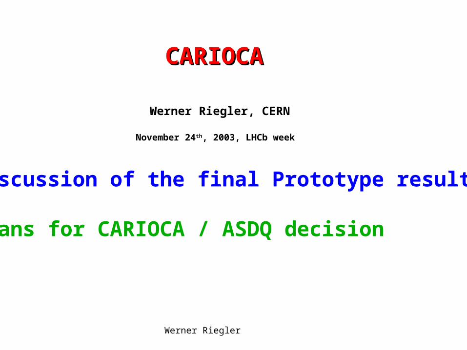
3x4mm chip
82 pins
25 pins on each side

Werner Riegler CERN, November 2003
CARIOCA10CARIOCA10
Traditionally one does extensive LAB tests before putting the Traditionally one does extensive LAB tests before putting the chip on the chamber. chip on the chamber.
Because our last testbeam period in T11 was October 22Because our last testbeam period in T11 was October 22ndnd to to Nov 11Nov 11thth , lab test are not yet finished … , lab test are not yet finished …
There is no way we could have advanced further up to now …There is no way we could have advanced further up to now …
CARIOCA10 was tested on M3R3 (4boards), GEM (6 boards) CARIOCA10 was tested on M3R3 (4boards), GEM (6 boards) and we fully equipped a CERN M3R1 chamber.and we fully equipped a CERN M3R1 chamber.
We found a nice way for high rate tests in GIF without having We found a nice way for high rate tests in GIF without having beam – this is also ongoing.beam – this is also ongoing.
Results are preliminaryResults are preliminary

Werner Riegler CERN, November 2003
CARIOCA10 test boardCARIOCA10 test boardWe wanted the results quickly, we don’t have the final package
We did an ‘optimum’ and ‘worst case’ package:
Optimum Package (‘no package’): •Chip bulk is glued to the board gound with conductive Epoxi,•Wire bonds are very short
Worst Case Package: •Chip bulk is insulated from the board gound • Wire bonds are very long

Werner Riegler CERN, November 2003
Sensitivity (discriminator)Sensitivity (discriminator)
On CARIOCA10, sensitivity was doubled in order to decrease minumum detectable charge (4fC2fC) for GEM application.
Maximum threshold is 300mV (limited by discriminator).
Sensitivity decreases by factor 2 from 0 to 220pF.

Werner Riegler CERN, November 2003
Sensitivity variationsSensitivity variations
Channel to channel variations are smaller than chip to chip variations

Werner Riegler CERN, November 2003
Sensitivity Variations, 0pFSensitivity Variations, 0pF
Pos: 16.0mV/fC, 0.56mV/fC r.m.s, i.e. 3.54%.
Pos: 14.5mV/fC, 0.62mV/fC r.m.s, i.e. 4.31% ‘package’ causes a decrease of 9%
Neg: 14.7mV/fC , 0.56mV/fC r.m.s., i.e. 3.8%
Neg: 13.1mV/fC, 0.56mV/fC i.e. 4.3% ‘package’ causes a decrease of 11%.

Werner Riegler CERN, November 2003
Sensitivity Variations,0pFSensitivity Variations,0pFSubtracting average per chip and scaling by Sqrt(8/7)
Pos: 16.0mV/fC, 0.34mV/fC r.m.s, i.e. 2.15%.
Pos: 14.5mV/fC, 0.34mV/fC r.m.s, i.e. 2.36%
Neg: 14.7mV/fC , 0.40mV/fC r.m.s., i.e. 2.7%
Neg: 13.1mV/fC, 0.26mV/fC i.e. 2.0%

Werner Riegler CERN, November 2003
Sensitivity VariationsSensitivity Variations
Sensitivity is 16(14.7) mV/fC for the positive (negative) amplifier.
Sensitivity variations are <5% r.m.s.
The DIALOG DACs have 2.44mV LSB I.e. 0.16 fC @ 0pF and
0.32 fC @ 220pF

Werner Riegler CERN, November 2003
Extrapol. Minumum Detectable ChargeExtrapol. Minumum Detectable Charge
2.4 fC, 0.37 fC r.m.s. 2.4 fC, 0.24fC r.m.s
Minumum detectable charge is correlated with the sensitivity, I.e. the reason for this Limit is a minimum voltage pulse at the Discriminator input in order to make it fire.

Werner Riegler CERN, November 2003
OffsetsOffsets
Offsets were measured on 272 channels by Offsets were measured on 272 channels by recording the threshold value that inverts the recording the threshold value that inverts the discriminator output.discriminator output.
One DTV sets the threshold for all 8 channels.One DTV sets the threshold for all 8 channels.

Werner Riegler CERN, November 2003
OffsetsOffsets
Channel to channel variations are smaller than chip to chip variations

Werner Riegler CERN, November 2003
OffsetsOffsets
795.6mV, 9.9mV r.m.s.
The threshold DACs on the DIALOG chip have a range of 625mV to 1250mV in 8 bits i.e. bins of 2.44mV.
This is perfectly compatible with this kind of offset spread.

Werner Riegler CERN, November 2003
OffsetsOffsets
Subtracting the average offset for each chip and multiplying by sqrt(8/7) gives an rms of 4.54mV.
This is the ‘true’ channel to channel variation.
It corresponds to 0.3fC at 0pF and 0.6fC at 220pF

Werner Riegler CERN, November 2003
The DTV applies the differential threshold voltage to the discriminator.

Werner Riegler CERN, November 2003
DTV itself has an offset of about 7.5mV r.m.s

Werner Riegler CERN, November 2003

Werner Riegler CERN, November 2003
Offsets+SensitivityOffsets+Sensitivity
The channel to channel variation of the The channel to channel variation of the sensitivity is <5%.sensitivity is <5%.
The channel to channel offset variation is The channel to channel offset variation is around 5mV r.m.s. around 5mV r.m.s.
Together with the DTV the channel to Together with the DTV the channel to channel offset variation is 10mV r.m.s.channel offset variation is 10mV r.m.s.
Both variations become ‘irrelevant’ when Both variations become ‘irrelevant’ when we use individual thresholds.we use individual thresholds.

Werner Riegler CERN, November 2003
NoiseNoise
Neg: 2240+42e-/pF At 0/100/200pF we can use Pos: 1880+45e-/pF threshold of 1.5/5/10 fC.

Werner Riegler CERN, November 2003
Power ConsumptionPower Consumption
Power consumption is 43.3/46.6 mW/channel for the positive/negative amplifier.
On on board (16 channels) the CARIOCA consumes 0.75W.
+DIALOG+Voltage drop from regulator….

Werner Riegler CERN, November 2003
Chamber Test in T11Chamber Test in T11
M3R1 module 1 chamber (double cathode M3R1 module 1 chamber (double cathode readout)readout)
Uniformity of this chamber was measured Uniformity of this chamber was measured with CARIOCA9 for the CERN PRR.with CARIOCA9 for the CERN PRR.
Crosstalk for single/double cathode readout Crosstalk for single/double cathode readout was evaluated for this chamber with was evaluated for this chamber with CARIOCA9.CARIOCA9.

Werner Riegler CERN, November 2003
HVGas
5,12 6,11 7,10 8,9
1,16 2,15 3,14 4,13
5,12 6,11 7,10 8,9
1,16 2,15 3,14 4,13
8,9 7,10 6,11 5,12
4,13 3,14 2,15 1,16
8,9 7,10 6,11 5,12
4,13 3,14 2,15 1,16
4,13 3,14 2,15 1,16
8,9 7,10 6,11 5,12
4,13 3,14 2,15 1,16
8,9 7,10 6,11 5,12
1,16 2,15 3,14 4,13
5,12 6,11 7,10 8,9
1,16 2,15 3,14 4,13
5,12 6,11 7,10 8,9
P14
P16
P13
P15
P9
P10
P11
P12
N3 N4 N5 N6 N7 N8 S1S2, no packageS3S4, package
Beam goesinto the drawing
master test

Werner Riegler CERN, November 2003
Chamber test in T11Chamber test in T11

Werner Riegler CERN, November 2003
Chamber test T11Chamber test T11Dialog -1

Werner Riegler CERN, November 2003
Chamber test T11Chamber test T11
Offsets are corrected by 194 individual thresholds. This will finally be done by DIALOG …

Werner Riegler CERN, November 2003
Chamber test T11Chamber test T11
All outputs were connected to the LVDS-ECL converter with our ‘final’ shielded twisted pair cables.
Werner Riegler CERN, November 2003
Chamber Test in T11Chamber Test in T11
We used 45mV threshold (We used 45mV threshold (6-7fC) on all 196 6-7fC) on all 196 channels.channels.
All channels had <50Hz dark count rate.All channels had <50Hz dark count rate.
Excellent stability Excellent stability ‘without’ dummy capacitor ‘without’ dummy capacitor and without shielding !and without shielding !

Werner Riegler CERN, November 2003
Symmetric TerminationSymmetric TerminationDue to the large detector capacitance the frontend is extremely sensitive to ground noise (Cdet=100pF, 5050VV fires the 5fC threshold).
With symmetric termination the chip becomes ‘immune’ to this effect. Penalty: larger noise !
‘Up to CARIOCA8’ we needed this dummy capacitor since the discriminator firing was causing a large pulse on the chip ground.
For CARIOCA9/10, many measures were taken in order to reduce this coupling, especially disconnection of substrate contacts in transistors of the digital part.
With the final prototype things work perfectly fine without the dummy capacitor, but we still have this option !

Werner Riegler CERN, November 2003
HV
Threshold 7.6,7.4 6.9,7.0 6.7,6.6 5.9,6.2 fC
7.3,6.6 7.3,6.2 6.6,6.8 6.5,6.5 fC
Noise 1.3,1.3 1.3,1.2 1.1,1.3 0.6,1.1 fC
1.3,1.3 1.3,1.1 1.1,1.1 1.1,1.2 fC
Capacitance 112 108 98 88
45mV threshold on all Pads - Cathode Pad numbers:

Werner Riegler CERN, November 2003
HV
Wire Pad Capacitances 26.5-28.5pF
Thresholds 6.2, 7.4 fC
Noise 0.67, 0.69 fC
45mV threshold on all pads: wire pad numbers

Werner Riegler CERN, November 2003
Cathode EfficiencyCathode Efficiency
95% 2.42kV99% 2.54kV
95% 2.45kV99% 2.56kV

Werner Riegler CERN, November 2003
Wire EfficiencyWire Efficiency
95% 2.4kV99% 2.5kV
95% 2.43kV99% 2.55kV

Werner Riegler CERN, November 2003
Detector CapacitanceDetector Capacitance The cathode pad capacitance in the entire muon The cathode pad capacitance in the entire muon
system will not exceed system will not exceed 120pF, so with the M3R1 120pF, so with the M3R1 chamber we have already tested chamber we have already tested the largest the largest cathode capacitances !cathode capacitances !
We will however have wire pad chambers with We will however have wire pad chambers with capacitance up to capacitance up to 220 pF (R4) while the M3R1 220 pF (R4) while the M3R1 chamber has only 30pF wire pad capacitances.chamber has only 30pF wire pad capacitances.
Since we don’t have a wire pad chamber we Since we don’t have a wire pad chamber we measured the efficiency by adding capacitors to the measured the efficiency by adding capacitors to the wire pad.wire pad.

Werner Riegler CERN, November 2003
On Chamber Wire pad NoiseOn Chamber Wire pad Noise
On Chamber Noise
0
0.5
1
1.5
2
2.5
0 50 100 150 200 250 300
Wire Pad Capacitance (pF)
No
ise
(fC
)
Series1
Series2
packaged and non packaged chip

Werner Riegler CERN, November 2003
Wire Pad Efficiency for Wire Pad Efficiency for different Capacitancesdifferent Capacitances
nonpackage side package side

Werner Riegler CERN, November 2003
EfficiencyEfficiency
2.5kV is a good working point that gives 2.5kV is a good working point that gives >95% efficiency on the double gap (>99% >95% efficiency on the double gap (>99% on the quad gap).on the quad gap).
2.65kV is a good working point that gives 2.65kV is a good working point that gives >99% efficiency on the double gap.>99% efficiency on the double gap.

Werner Riegler CERN, November 2003
CrosstalkCrosstalk
Crosstalk: Probability of firing the Neighboring pad (infinite time window)
Plot presented at the PRR:
Measured with CARIOCA9 on the M1R3Prototype on Pad Position P9,7/10.
We decided to use doubel cathode readoutsince we can survive with 10% crosstalk.
In M2M3R1R2 the trigger granularity is given by the wire pads, not the cathode Pads.
Crosstalk ‘only’ increases the rate.
Werner Riegler CERN, November 2003
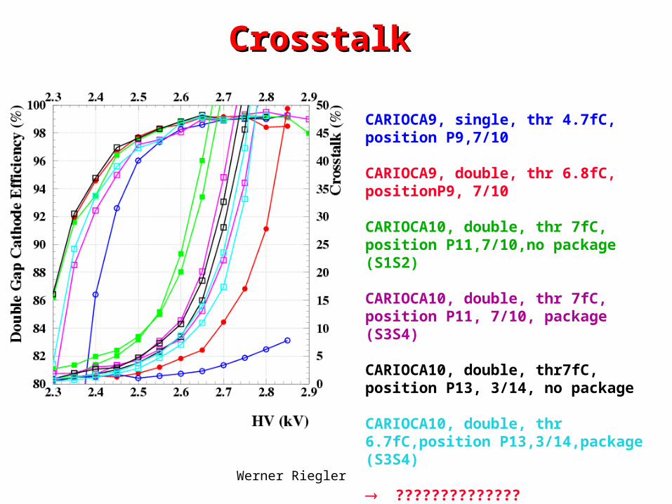
CrosstalkCrosstalk
CARIOCA9, single, thr 4.7fC, position P9,7/10
CARIOCA9, double, thr 6.8fC, positionP9, 7/10
CARIOCA10, double, thr 7fC, position P11,7/10,no package (S1S2)
CARIOCA10, double, thr 7fC, position P11, 7/10, package (S3S4)
CARIOCA10, double, thr7fC, position P13, 3/14, no package
CARIOCA10, double, thr 6.7fC,position P13,3/14,package (S3S4)
??????????????

Werner Riegler CERN, November 2003
CrosstalkCrosstalk
The preamp input stage was actually changed for CARIOCA10 in order to improve the signal tail at large capacitances (phase margin).
The design value was 50 since from simulations we know that this is a good value (ASDQ++ used 25 ).
Werner Riegler CERN, November 2003
Crosstalk FractionCrosstalk Fraction
Injecting a delta signal in one pad finds a Injecting a delta signal in one pad finds a signal on a neighbour pad.signal on a neighbour pad.
We call the ratio of the two pulse heights We call the ratio of the two pulse heights the crosstalk fraction.the crosstalk fraction.

Werner Riegler CERN, November 2003
HV
1.7% 1.4%1.5%1.8% 1.5% 1.4% 1.7% 1.5%1.4%1.7% 1.5% 1.4%
CARIOCA9
2.1% 1.7%1.6%2.2% 1.6% 1.7% 2.2% 1.6%1.6%2.1% 1.6% 1.7%
CARIOCA10
Crosstalk Fraction

Werner Riegler CERN, November 2003
Crosstalk FractionCrosstalk Fraction The crosstalk fraction of the M3R1 chamber using The crosstalk fraction of the M3R1 chamber using
CARIOCA10 is 1.6-2.2%.CARIOCA10 is 1.6-2.2%.
It is 10-30% larger than for CARIOCA9. It is 10-30% larger than for CARIOCA9.
This is a small increase and the 2.2% crosstalk This is a small increase and the 2.2% crosstalk fraction is well within our specifications.fraction is well within our specifications.
Some time ago we found that we have >95% efficiency Some time ago we found that we have >95% efficiency if our threshold is at <30% of the average signal and if our threshold is at <30% of the average signal and >99% efficiency of our threshold is <20% of the >99% efficiency of our threshold is <20% of the average signal (1.5mm pitch).average signal (1.5mm pitch).
With a crosstalk fraction of 20% and 2.2% crosstalk With a crosstalk fraction of 20% and 2.2% crosstalk fraction there is no way to have such a large fraction there is no way to have such a large crosstalk !crosstalk !

Werner Riegler CERN, November 2003
CrosstalkCrosstalk
Simulated Pulse Height Spectrum
MEDIAN is at 50.
Crosstalk is defined as the probabilityThat a neighbor pad fires.This depends on Gas Gain and threshold.
Crosstalk Fraction is defined as the fraction of Pulse height on a neighbor pad.This is defined by the pad-pad capacitance and Can be measured in the lab.

Werner Riegler CERN, November 2003
CrosstalkCrosstalkThreshold (fraction of MEDIAN) 1% 2% 3% 4% 5% 6% 7% 8% 9% 10%
11%
12%....
20%

Werner Riegler CERN, November 2003
Threshold CalibrationThreshold CalibrationAt the point where the hitefficiency is 50%, the threshold is at the MEDIAN Pulse Height.
The voltage where the double gap efficiency is 95% marks the beginning of our plateau.
The voltage where the double gap shows99% efficiency is difficult to find. Therefore we define it as the voltage Where the single gap efficiency exceeds90%.
Knowing the gas gain curve allows To define the threshold in terms of
Fraction of the MEDIAN signal.
Easy to obtain !
Werner Riegler CERN, November 2003
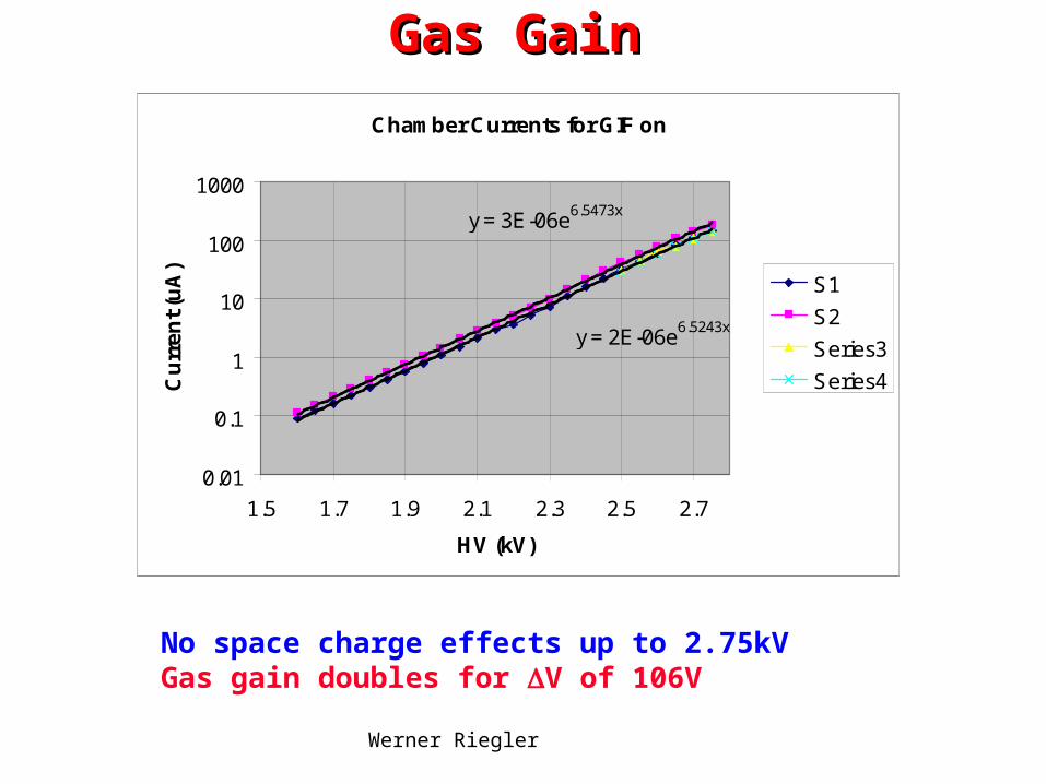
Gas GainGas Gain
No space charge effects up to 2.75kVGas gain doubles for V of 106V
Chamber Currents for GIF on
y = 3E-06e6.5473x
y = 2E-06e6.5243x
0.01
0.1
1
10
100
1000
1.5 1.7 1.9 2.1 2.3 2.5 2.7
HV (kV)
Cu
rre
nt
(uA
)
S1
S2
Series3
Series4
Werner Riegler CERN, November 2003
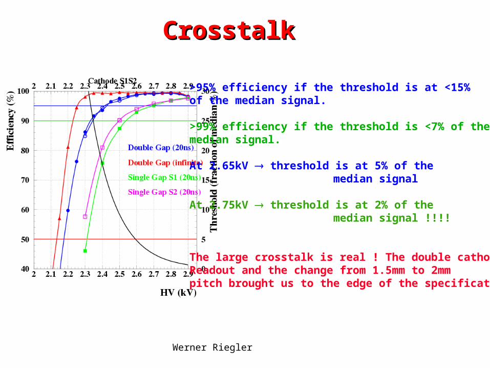
CrosstalkCrosstalk
>95% efficiency if the threshold is at <15% of the median signal.
>99% efficiency if the threshold is <7% of the median signal.
At 2.65kV threshold is at 5% of the median signal
At 2.75kV threshold is at 2% of the median signal !!!!
The large crosstalk is real ! The double cathodeReadout and the change from 1.5mm to 2mm pitch brought us to the edge of the specifications !

Werner Riegler CERN, November 2003
High Rate TestsHigh Rate TestsInefficiency due to signal pileup.
Since the muon trigger uses a 5 out of 5 coincidence, each of the 5 stations has to be >99% efficient.
Therefore the signal width is a crucial number. It is not only determined by the electronics, there is a detector intrinsic Dead time due to arrival of the electrons.
Since we use an OR of two frontend channels per station, the rate of correlated hits is the crucial number.
For uncorrelated hits, we still have 99% efficiency per station even if one frontend (double gap) has only 90% efficiency.
Out goal is a dead time of <50-60ns.
In addition to the deadtime (geometrical) we have of course some baseline fluctuations …
1.5mm pitch, Arrival time of the last electron is 25ns.

Werner Riegler CERN, November 2003
High Rate TestsHigh Rate Tests
Positive Amplifier Negative Amplifier
Am241 is definitely a ‘worst case’ background signal (60keV gamma)

Werner Riegler CERN, November 2003
Charge/Hit at GIFCharge/Hit at GIF
charge/hit
0
0.5
1
1.5
2
2.5
3
2.3 2.4 2.5 2.6 2.7
HV (kV)
Ch
arg
e (p
C)
charge/hit (pC)
Mip (pC)
Cs 137, 662keV gammas
Dividing the total chamber current by the count rate at 7fC threshold.
The MIP charge is calculated by assuming 100e-/cm and a measured gain curve, It is not a very reliable number …..
Werner Riegler CERN, November 2003
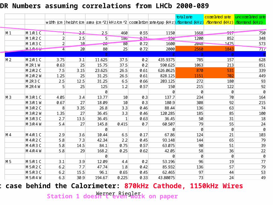
TDR Numbers assuming correlations from LHCb 2000-089total rate correlated rate uncorrelated rate
width (cm) height (cm)area (cm 2̂) kHz/cm^2 correlation rate/gap (kHz) /frontend (kHz) /frontend (kHz) /frontend (kHz)
M1 M1/R1 C 1 2.5 2.5 460 0.55 1150 1668 917 750M1/R2 C 2 2.5 5 186 0.71 930 1200 852 348M1/R3 C 2 10 20 80 0.72 1600 2048 1475 573M1/R4 W 4 20 80 25 0.72 2000 2560 1843 717
0 0 0 0 0M2 M2/R1 C 3.75 3.1 11.625 37.5 0.2 435.9375 785 157 628
M2R1 W 0.63 25 15.75 37.5 0.2 590.625 1063 213 851M2/R2 C 7.5 3.15 23.625 26.5 0.61 626.0625 870 531 339M2/R2 W 1.25 25 31.25 26.5 0.61 828.125 1151 702 449M2R3 C 2.5 12.5 31.25 6.5 0.66 203.125 272 180 93M2R4 W 5 25 125 1.2 0.57 150 215 122 92
0 0 0 0 0M3 M3/R1 C 4.05 3.4 13.77 10 0.3 137.7 234 70 164
M3/R1 W 0.67 27 18.09 10 0.3 180.9 308 92 215M3/R2 C 8 3.35 26.8 3.3 0.46 88.44 136 63 74M3/R2 W 1.35 27 36.45 3.3 0.46 120.285 185 85 100M3/R3 C 2.7 13.5 36.45 1 0.63 36.45 50 31 18M3/R4 W 5.4 27 145.8 0.415 0.7 60.507 79 55 24
0 0 0 0 0M4 M4/R1 C 2.9 3.6 10.44 6.5 0.17 67.86 124 21 103
M4/R2 C 5.8 7.3 42.34 2.2 0.45 93.148 144 65 79M4/R3 C 5.8 14.5 84.1 0.75 0.57 63.075 90 51 39M4/R4 W 5.8 29 168.2 0.25 0.62 42.05 58 36 22
0 0 0 0 0M5 M5/R1 C 3.1 3.9 12.09 4.4 0.2 53.196 96 19 77
M5/R2 C 6.2 7.7 47.74 1.8 0.42 85.932 136 57 79M5/R3 C 6.2 15.5 96.1 0.65 0.45 62.465 97 44 53M5/R4 W 6.3 30.9 194.67 0.225 0.33 43.80075 73 24 49
Worst case behind the Calorimeter: 870kHz Cathode, 1150kHz Wires
Station 1 doesn’t even work on paper
Werner Riegler CERN, November 2003
High Rate Tests at GIFHigh Rate Tests at GIF
In the experiment we will have high energy muons in presence of ‘photon’ (electron) background.
The ideal situation is the muon beam at GIF.
We didn’t have time to do this test – next chance only may next year.
There is another way of testing the high rate behaviour I.e. signal pileup and baseline fluctuations – S-curve in presence of the background particles.

Werner Riegler CERN, November 2003
High Rate Tests at GIFHigh Rate Tests at GIFChamber was positioned very close to the source.
Threshold set to 7fC like in the T11 testbeam.
Rated/frontend
0
500
1000
1500
2000
1.7 1.9 2.1 2.3 2.5 2.7
HV (kV)
Rat
e (k
Hz)
wire rate
cathode rate
At out working Point of 2.5kV we find exactly the maximum rates expected in the experiment (behind Calo)
1255kHz wires920kHz cathodes
Rate increases with HV because of the Compton spectrum …
The steep increase on the Cathodes is due to the crosstalk

Werner Riegler CERN, November 2003
S-Curve at High RateS-Curve at High RateInject a signal delta signal on the pad and count the coincidence of the Chamber output signal with a correlated 20ns gate.
With source off one gets the ‘standard S-curve.
With source on one gets all the information on rate, efficiency and baseline fluctuations.
Cathode, 2.65kV
0
0.2
0.4
0.6
0.8
1
1.2
0 10 20 30 40 50
Injected Charge (fC)
Co
un
t R
ate
(%)
Rate
EfficiencyBaseline
Derivative givesthe noise+baselineFluctuation.

Werner Riegler CERN, November 2003
S-Curves at GIFS-Curves at GIFCathode
0
0.2
0.4
0.6
0.8
1
1.2
0 10 20 30 40 50
Injected Charge (fC)
Co
inc
ide
nc
e C
ou
nts
(%
)
Series1
Series2
Series3
Wire
0
0.2
0.4
0.6
0.8
1
1.2
0 10 20 30 40
Injected Charge (fC)
Co
inc
ide
nc
e C
ou
nts
(%
)
counts (norm)
Series2
counts (norm)
0, 2.5, 2.65 kV 0, 2.5, 2.65 kV

Werner Riegler CERN, November 2003
EfficiencyEfficiency
75
80
85
90
95
100
105
2.2 2.3 2.4 2.5 2.6 2.7 2.8
HV (kV)
Eff
icie
ncy
(%
)
wire efficiency (%)
cathode efficiency(%)
Rated/frontend
0
500
1000
1500
2000
2.2 2.3 2.4 2.5 2.6 2.7 2.8
HV (kV)
Rat
e (k
Hz)
wire rate
cathode rate
EfficiencyEfficiency>99% efficiency at low rate
About 4% ‘geometric’ Efficiency loss at 2.65 kV and 1.5MHz !
Compatible with <50ns deadtime. !

Werner Riegler CERN, November 2003
NoiseNoise
Cathode
-0.05
0
0.05
0.1
0.15
0.2
0.25
0.3
0 10 20 30 40 50
Injected Charge (fC)
Der
ivat
ive Series1
Series2
derivative
Noise increases ‘slightly’ with the rate.
Has to be evaluated more
carefully …
Derivative of the S-curve gives the ‘Baseline Probability’ (Noise+Baseline fluctuations)
0, 2.5, 2.65 kV

Werner Riegler CERN, November 2003
ConclusionsConclusions Up to now, CARIOCA10 works according to specifications. Up to now, CARIOCA10 works according to specifications.
Still missing: Analog shapes, test pulse feature, input resistance, Still missing: Analog shapes, test pulse feature, input resistance, radiation tests, input protection, large pulse baseline recovery, ….radiation tests, input protection, large pulse baseline recovery, ….
DIALOG will arrive DIALOG will arrive Feb1st 2004 Feb1st 2004 There is still enough time for There is still enough time for CARIOCA tests.CARIOCA tests.
In case we will find a problem on CARIOCA10 we will have to consider a In case we will find a problem on CARIOCA10 we will have to consider a submission in Q1 of 2004 which would shift our milestones but would not submission in Q1 of 2004 which would shift our milestones but would not kill us. kill us.
Francis Anghinolfi agreed to do the design changes in case it is Francis Anghinolfi agreed to do the design changes in case it is necessary.necessary.
The DIALOG still contains the ASDQ features, I.e. we are still free to chose The DIALOG still contains the ASDQ features, I.e. we are still free to chose …..…..
We have to understand M1 and all background rates much better We have to understand M1 and all background rates much better
We should by no means exceed 1MHz rate/fronted. We should by no means exceed 1MHz rate/fronted.