
Well foundation pdf
28
A Dep Anantrao P CE 323-TE Seminar Report By Alauddin Aziz-ul-Haq Khan (T121100023) Under the guidance of Prof. Supriya Shinde partment of Civil Engineering Pawar College Of Engineering,Pune March,2015
-
Upload
anantrao-pawar-college-of-engg -
Category
Presentations & Public Speaking
-
view
1.044 -
download
13
Transcript of Well foundation pdf

A
Department of Civil Engineering
Anantrao Pawar College Of Engineering,Pune
CE 323-TE Seminar Report
By
Alauddin Aziz-ul-Haq Khan
(T121100023)
Under the guidance of
Prof. Supriya Shinde
Department of Civil Engineering
Anantrao Pawar College Of Engineering,Pune
March,2015
Certificate
Certified that this T.E .Seminar Report titled "Well Foundation" by "Alauddin Aziz-ul-Haq Khan" is approved by me for submission.Certified further that to the best of my knowledge,the report represents work carried out by the student.
Date: Signature:
05/03/2015 Prof.Supriya Shinde
Acknowledgement
It is our privilege to express our sincerest regards to our project teacher. Prof. Supriya Shinde
mam and our class Teacher Prof.Vishal Bhoite sir, for their valuable inputs, able guidance, encouragement,
whole-hearted cooperation and constructive criticism throughout the duration of our project.
We deeply express our sincere thanks to our Head of Department Prof.Sagar Gavande for
encouraging and allowing us to present the project on the topic "WELL FOUNDATION" at our department
premises for the partial fulfillment of the requirements .
I extend my gratitude to Anantrao Pawar College Of Engineering & Research for giving me this
opportunity.
I take this opportunity to thank all our lecturers who have directly or indirectly helped our project.
We pay our respects and love to our parents and all other family members and friends for their love and
encouragement through out our career. Last but not the least we express our thanks to our friends for their
cooperation and support.
Thanking You.
Alauddin Aziz-Ul-Haq Khan

ABSTRACT
Well foundations had their origin in India and have been used for Hundred of years, for
providing deep foundations, for important buildings and structures. The techniques of sinking masonary wells
for drinking water is very ancient. Same technique was used for construction of foundation wells in the earlier
stage. Well foundations were freely used during the Mughal period and many of the Mughal monuments
including the Taj Mahal have got well foundations .The Mughal used well foundation for bridges across major
river also .But these bridges were washed away within a few years as the mechanism of scour was not
understood.
In spite of the excellent development of technology on well foundations there are still some
areas where engineers face difficulty while sinking of wells, some of which are stated in this paper from the
direct experience.
Well foundations are quite appropriate foundations for alluvial soils in rivers and creeks where
maximum depth of scour can be quite large. In India technology of well foundation for design and construction
is quite well developed. Still there are situations where serious problems are encountered at site during
construction of well foundations. Some of the typical problems have been identified and solutions adopted by
the author and also elsewhere in some earlier jobs have been presented in this topic.
1.Introduction
In the Indian subcontinent there are many rivers where the depth of alluvial deposits is very
high and the scour around the pier foundations can be very deep if the piers are located within the active
channel of river. For such condition well foundation is a very appropriate type of foundation. As per our
knowledge one 3 km long Railway bridge crossing a creek was supported on pile foundations. After some
years, the sway of the pile foundations was so large when the mail trains crossed the creek; the Railways not
only reduced the speed of the trains substantially but constructed another bridge adjacent to this bridge on well
foundations. Thus under certain situation, well foundation is a highly desirable type of foundation. In India the
technology for the design and construction of well foundation is quite advanced.
In all rivers, including large rivers with torrential flow of water currents, well foundations
were provided. In the foundations of Howrah Bridge in Kolkata giant monoliths were provided. In Second
Hoogly Bridge also in Kolkata with one of the longest span cable stayed bridges in the world having the central
span of 457 m being same as that of Howrah Bridge, an in genius solution was adopted. Instead of a monolith
for the foundation of each tower of the cable stay bridge, 2 well foundations up to 23 m diameter were placed
side by side at 30 m center and interconnected by a 14 m deep beam. This solution was construction-wise easier
and more controllable and quantity of material used was much less. These wells were constructed purely by
gravity sinking method. These well foundations under main towers were kept totally empty for the service
condition
The entire well was designed as a water tight structure. At the junction of any two lifts of concreting
of well staining, water stops were provided to prevent leakage of water through construction joints of well
staining. The wells were constructed using gravity sinking method of construction. As stated earlier, the wells
were kept totally empty and no water was inside the well during the service condition primarily to reduce the
load of water on the foundations, since vertical loads were very large for the central spans of 457 m and side
spans of 183 m.
At the base of wells RCC slabs were constructed which were designed for the upward force from
the base of the well. For support of the slab and continuity of reinforcement, recesses were kept in the staining
above the well curb where bond bar reinforcements were kept bent. A cover was provided with a steel plate
which, were kept in position by bolts, to keep the bond reinforcement recesses free from blocking with mud’s. .
After the wells were sunk up to the designed level, the bottom plug was laid with concrete. The wells were
dewatered. It was noted that the concrete bottom plug not only withstood the upward pressure but also was
reasonably leak proof. Thereafter, those steel plate covers were removed and reinforcements were bent back to
the designed positions. Reinforcements were laid and concreting was done. In this way a fully water tight
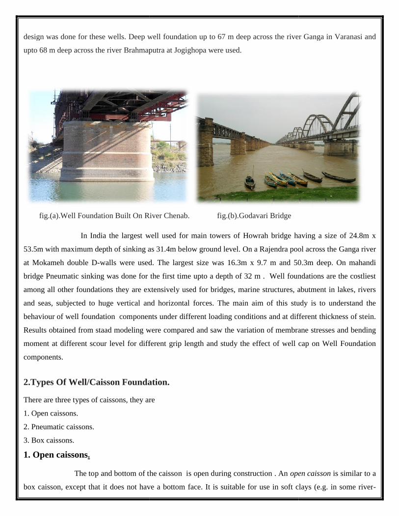
design was done for these wells. Deep well foundation up to 67 m deep acros
upto 68 m deep across the river Brahmaputra at Jogighopa were used.
fig.(a).Well Foundation Built On River Chenab. fig.(b).Godavari Bridge
In India the largest well used for main towers of Howrah bridge having a size of 24.8m x
53.5m with maximum depth of sinking as 31.4m below ground level.
at Mokameh double D-walls were used.
bridge Pneumatic sinking was done for the first time upto a depth of 32 m . Well foundations are the costliest
among all other foundations they are extensively used for bridges, marine structures, abutment in lakes
and seas, subjected to huge vertical and horizontal forces.
behaviour of well foundation components under different loading conditions and at different thickness of stein.
Results obtained from staad modeling were compared and saw the variation of membrane stresse
moment at different scour level for different grip length and study the effect of well cap on Well Foundation
components.
2.Types Of Well/Caisson Foundation.
There are three types of caissons, they are
1. Open caissons.
2. Pneumatic caissons.
3. Box caissons.
1. Open caissons.
The top and bottom of the caisson is open during construction . An
box caisson, except that it does not have a bottom face. It is suitable for use in soft clays (e.g. in some river
design was done for these wells. Deep well foundation up to 67 m deep across the river Ganga in Varanasi and
upto 68 m deep across the river Brahmaputra at Jogighopa were used.
fig.(a).Well Foundation Built On River Chenab. fig.(b).Godavari Bridge
In India the largest well used for main towers of Howrah bridge having a size of 24.8m x
53.5m with maximum depth of sinking as 31.4m below ground level. On a Rajendra pool across the G
walls were used. The largest size was 16.3m x 9.7 m and 50.3m deep.
bridge Pneumatic sinking was done for the first time upto a depth of 32 m . Well foundations are the costliest
among all other foundations they are extensively used for bridges, marine structures, abutment in lakes
and seas, subjected to huge vertical and horizontal forces. The main aim of this study is to understand the
behaviour of well foundation components under different loading conditions and at different thickness of stein.
d modeling were compared and saw the variation of membrane stresse
moment at different scour level for different grip length and study the effect of well cap on Well Foundation
oundation.
they are
The top and bottom of the caisson is open during construction . An open caisson
box caisson, except that it does not have a bottom face. It is suitable for use in soft clays (e.g. in some river
s the river Ganga in Varanasi and
In India the largest well used for main towers of Howrah bridge having a size of 24.8m x
On a Rajendra pool across the Ganga river
16.3m x 9.7 m and 50.3m deep. On mahandi
bridge Pneumatic sinking was done for the first time upto a depth of 32 m . Well foundations are the costliest
among all other foundations they are extensively used for bridges, marine structures, abutment in lakes, rivers
The main aim of this study is to understand the
behaviour of well foundation components under different loading conditions and at different thickness of stein.
d modeling were compared and saw the variation of membrane stresses and bending
moment at different scour level for different grip length and study the effect of well cap on Well Foundation
open caisson is similar to a
box caisson, except that it does not have a bottom face. It is suitable for use in soft clays (e.g. in some river-
beds), but not for where there may be large obstructions in the ground. An open caisson that is used in soft
grounds or high water tables, where open trench excavations are impractical, can also be used to install deep
manholes, pump stations and reception/launch pits for micro tunnelling , pipe jacking and other operations.
A caisson is sunk by self-weight, concrete or water ballast placed on top, or by hydraulic jacks.
The leading edge (or cutting shoe) of the caisson is sloped out at a sharp angle to aid sinking in a vertical
manner; it is usually made of steel. The shoe is generally wider than the caisson to reduce friction, and the
leading edge may be supplied with pressurised bentonite slurry, which swells in water, stabilizing settlement by
filling depressions and voids. An open caisson may fill with water during sinking. The material is excavated by
clamshell excavator bucket on crane.
The formation level subsoil may still not be suitable for excavation or bearing capacity. The water in the caisson
(due to a high water table) balances the up thrust forces of the soft soils underneath. If dewatered, the base may
"pipe" or "boil", causing the caisson to sink. To combat this problem, piles may be driven from the surface.
Depending upon their shape, open caissons can be further classified as,.
(i) Single wall open caisson(ii) Cylindrical open caisson(iii) Open caisson with dredging wells.
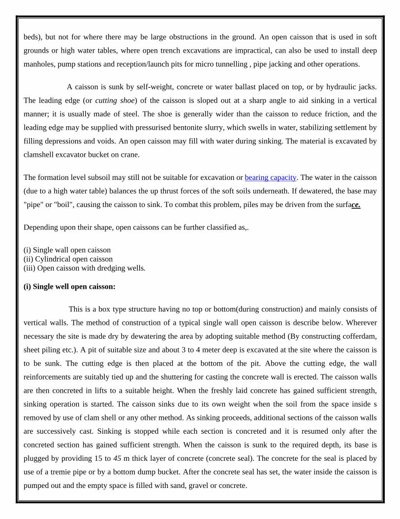
(i) Single well open caisson:
This is a box type structure having no top or bottom(during construction) and mainly consists of
vertical walls. The method of construction of a typical single wall open caisson is describe below. Wherever
necessary the site is made dry by dewatering the area by adopting suitable method (By constructing cofferdam,
sheet piling etc.). A pit of suitable size and about 3 to 4 meter deep is excavated at the site where the caisson is
to be sunk. The cutting edge is then placed at the bottom of the pit. Above the cutting edge, the wall
reinforcements are suitably tied up and the shuttering for casting the concrete wall is erected. The caisson walls
are then concreted in lifts to a suitable height. When the freshly laid concrete has gained sufficient strength,
sinking operation is started. The caisson sinks due to its own weight when the soil from the space inside s
removed by use of clam shell or any other method. As sinking proceeds, additional sections of the caisson walls
are successively cast. Sinking is stopped while each section is concreted and it is resumed only after the
concreted section has gained sufficient strength. When the caisson is sunk to the required depth, its base is
plugged by providing 15 to 45 m thick layer of concrete (concrete seal). The concrete for the seal is placed by
use of a tremie pipe or by a bottom dump bucket. After the concrete seal has set, the water inside the caisson is
pumped out and the empty space is filled with sand, gravel or concrete.
The rate of sinking of the caisson is always slow because the downward moment of the caisson is resisted by the
skin friction of the ground on its walls. At times the skin friction becomes so great that the caisson does not sink
even after all the earth has been dredged out from the inside clean down to the cutting edge. In such situations,
sinking is resorted to by loading the caisson with additional weights in the form of rails, ingots etc. which are
removed afterwards.
(ii) Cylindrical open caisson (well):
This may be defined as a cylindrical shell made up of timber, masonry, steel or reinforced
concrete shod with a cutting edge and which is sunk by excavating the soil within the shell. The thickness of the
caisson wall must be adequate so that when the inside soil is dredged out, it sinks under its own weight. To
facilitate sinking of the caisson water jets are sometimes used around the sides which decrease the skin friction.
Cylindrical open caisson is also known as well caisson. This type of caisson is similar in all respect to the single
wall open caisson except that its wall is circular in plan. The method of construction of well caisson is exactly
similar to that of a single wall open caisson described earlier. After the well is sunk to the desired depth its
bottom is sealed with concrete. This type of caisson is commonly adopted for providing foundation for bridges
and other structure to be built in rivers and waterways
(iii) Open caisson with dredging wells:
This type of caisson has the distinction of being employed for the deepest foundation for, bridge piers,
abutments and other similar structures. The caisson in this case is rectangular or square in plan and is further
sub-divided into smaller sections from inside forming open walls. The outside walls as well as the inside divider
walls are normally made up of reinforced concrete. The caisson is sunk by excavating soil through the wells by
means of dredges. After the caisson is sunk to the required depth, its base is plugged with a concrete seal and
the walls are filled with sand or concrete. From the point of view of control during sinking, this type of caisson
has definite advantage over the other types described earlier. In this case, any tendency of the caisson to tilt or
to drift from its position during the process of sinking, can be checked by dredging the soil from the wells.
Advantages Of Open Caissons:-
1.The caissons can be constructed to a greater depths.
2.The construction cost is relatively low.

Disadvantages:-
1.The clearing and inspection of bottom of the caisson cannot be done.
2.Concrete seal placed in water will not be satisfactory.
3.The rate of progress will be slowed down if boulders are met during construction.
(2) Box caisson:
This type of caisson is similar to open caisson except that it is closed at bottom. The caisson is
cast and cured on land and when required, it is launched in water and towed to the site for sinking. The caisson
is sunk by filling sand, gravel, or concrete in the empty space inside. The place where the caisson base is to rest
must be levelled and as such box caissons are used in places where the strata of sufficient bearing capacity is
available near the ground. A box caisson
down on prepared bases. Once in place, it is filled with concrete to become part of the permanent works, such as
the foundation for a bridge pier. Hollow concrete structures float, so a box
anchored to prevent this phenomenon until it can be filled with concrete; adjustable anchoring systems,
combined with a GPS survey, allow engineers to position a box caisson with pinpoint accuracy. In normal
practice, the soft natural bottom soil of the river bed is dredged out to some depth and the trench thus formed is
clearing and inspection of bottom of the caisson cannot be done.
2.Concrete seal placed in water will not be satisfactory.
3.The rate of progress will be slowed down if boulders are met during construction.
fig.(c)-Open caissons
This type of caisson is similar to open caisson except that it is closed at bottom. The caisson is
cast and cured on land and when required, it is launched in water and towed to the site for sinking. The caisson
g sand, gravel, or concrete in the empty space inside. The place where the caisson base is to rest
must be levelled and as such box caissons are used in places where the strata of sufficient bearing capacity is
box caisson is a prefabricated concrete box (it has sides and a bottom); it is set
down on prepared bases. Once in place, it is filled with concrete to become part of the permanent works, such as
the foundation for a bridge pier. Hollow concrete structures float, so a box caisson must be ballasted or
anchored to prevent this phenomenon until it can be filled with concrete; adjustable anchoring systems,
combined with a GPS survey, allow engineers to position a box caisson with pinpoint accuracy. In normal
natural bottom soil of the river bed is dredged out to some depth and the trench thus formed is
This type of caisson is similar to open caisson except that it is closed at bottom. The caisson is
cast and cured on land and when required, it is launched in water and towed to the site for sinking. The caisson
g sand, gravel, or concrete in the empty space inside. The place where the caisson base is to rest
must be levelled and as such box caissons are used in places where the strata of sufficient bearing capacity is
prefabricated concrete box (it has sides and a bottom); it is set
down on prepared bases. Once in place, it is filled with concrete to become part of the permanent works, such as
caisson must be ballasted or
anchored to prevent this phenomenon until it can be filled with concrete; adjustable anchoring systems,
combined with a GPS survey, allow engineers to position a box caisson with pinpoint accuracy. In normal
natural bottom soil of the river bed is dredged out to some depth and the trench thus formed is
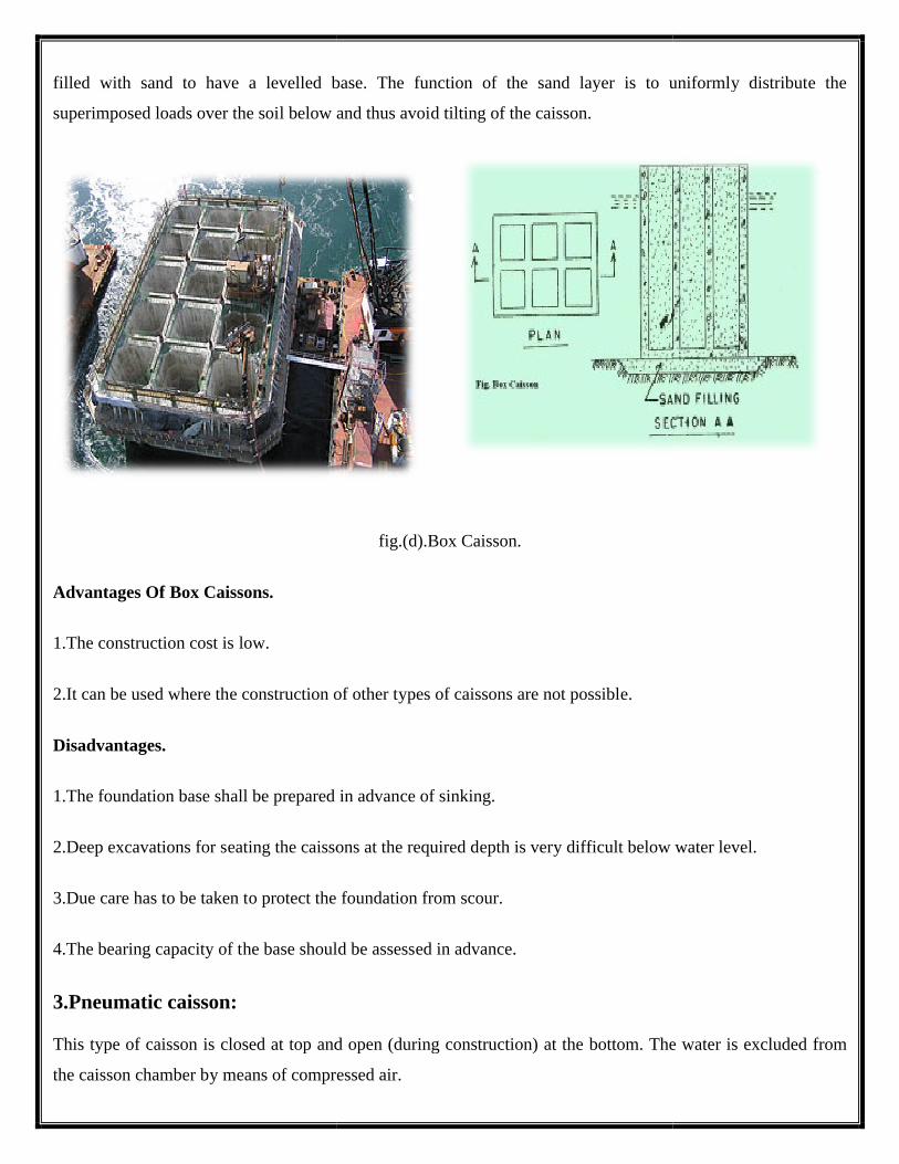
filled with sand to have a levelled base. The function of the sand layer is to uniformly distribute the
superimposed loads over the soil below and thus avoid t
Advantages Of Box Caissons.
1.The construction cost is low.
2.It can be used where the construction of other types of caissons are not possible.
Disadvantages.
1.The foundation base shall be prepared in advan
2.Deep excavations for seating the caissons at the required depth is very difficult below water level.
3.Due care has to be taken to protect the foundation from scour.
4.The bearing capacity of the base should be assessed in advance.
3.Pneumatic caisson:
This type of caisson is closed at top and open (during construction) at the bottom. The water is excluded from
the caisson chamber by means of compressed air.
filled with sand to have a levelled base. The function of the sand layer is to uniformly distribute the
superimposed loads over the soil below and thus avoid tilting of the caisson.
fig.(d).Box Caisson.
2.It can be used where the construction of other types of caissons are not possible.
all be prepared in advance of sinking.
2.Deep excavations for seating the caissons at the required depth is very difficult below water level.
3.Due care has to be taken to protect the foundation from scour.
4.The bearing capacity of the base should be assessed in advance.
This type of caisson is closed at top and open (during construction) at the bottom. The water is excluded from
the caisson chamber by means of compressed air.
filled with sand to have a levelled base. The function of the sand layer is to uniformly distribute the
2.Deep excavations for seating the caissons at the required depth is very difficult below water level.
This type of caisson is closed at top and open (during construction) at the bottom. The water is excluded from
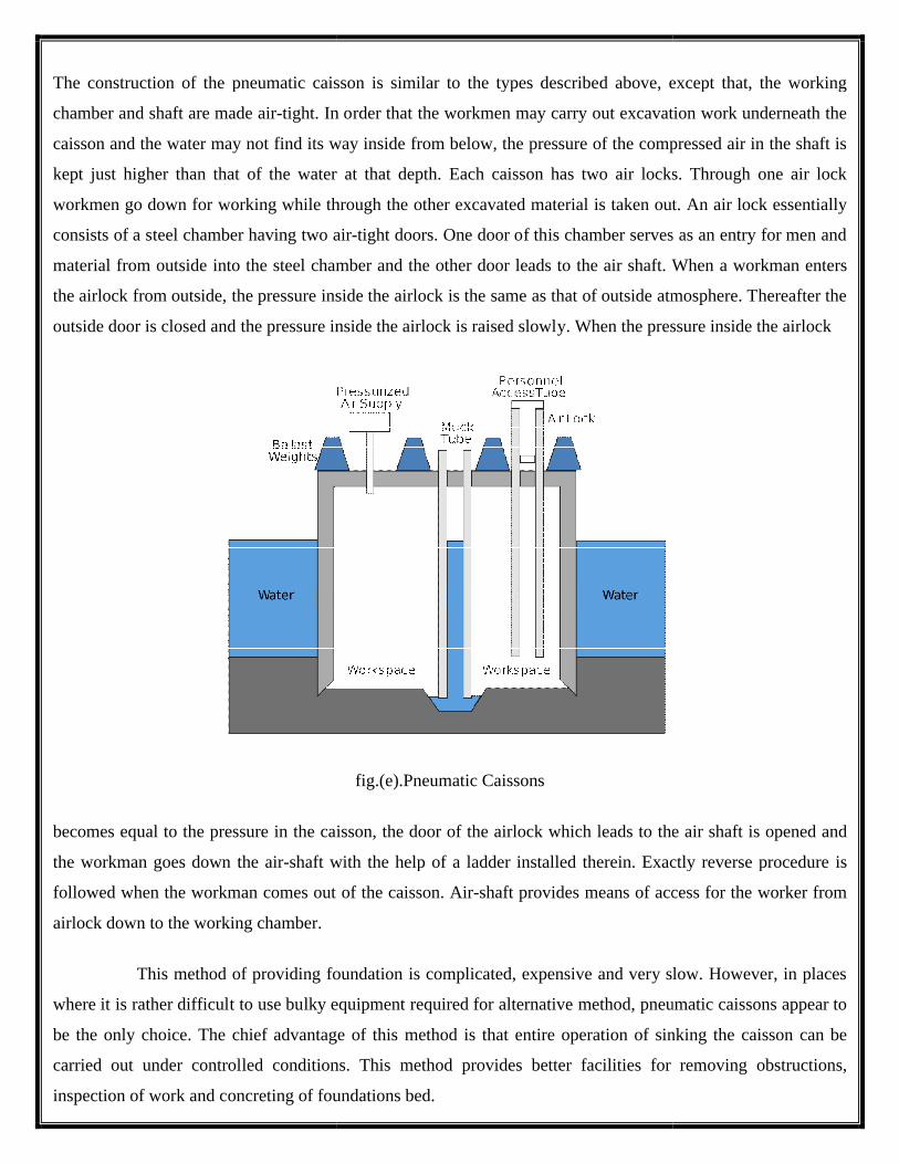
The construction of the pneumatic caisson is similar to the types describe
chamber and shaft are made air-tight. In order that the workmen may carry out excavation work underneath the
caisson and the water may not find its way inside from below, the pressure of the compressed air in the shaft is
kept just higher than that of the water at that depth. Each caisson has two air locks. Through one air lock
workmen go down for working while through the other excavated material is taken out. An air lock essentially
consists of a steel chamber having two air
material from outside into the steel chamber and the other door leads to the air shaft. When a workman enters
the airlock from outside, the pressure inside the airlock is the same as
outside door is closed and the pressure inside the airlock is raised slowly. When the pressure inside the airlock
becomes equal to the pressure in the caisson, the door of the airlock
the workman goes down the air-shaft with the help of a ladder installed therein. Exactly reverse procedure is
followed when the workman comes out of the caisson. Air
airlock down to the working chamber.
This method of providing foundation is complicated, expensive and very slow. However, in places
where it is rather difficult to use bulky equipment required for alternative method, pneumatic cais
be the only choice. The chief advantage of this method is that entire operation of sinking the caisson can be
carried out under controlled conditions. This method provides better facilities for removing obstructions,
inspection of work and concreting of foundations bed.
The construction of the pneumatic caisson is similar to the types described above, except that, the working
tight. In order that the workmen may carry out excavation work underneath the
caisson and the water may not find its way inside from below, the pressure of the compressed air in the shaft is
kept just higher than that of the water at that depth. Each caisson has two air locks. Through one air lock
workmen go down for working while through the other excavated material is taken out. An air lock essentially
air-tight doors. One door of this chamber serves as an entry for men and
material from outside into the steel chamber and the other door leads to the air shaft. When a workman enters
the airlock from outside, the pressure inside the airlock is the same as that of outside atmosphere. Thereafter the
outside door is closed and the pressure inside the airlock is raised slowly. When the pressure inside the airlock
fig.(e).Pneumatic Caissons
becomes equal to the pressure in the caisson, the door of the airlock which leads to the air shaft is opened and
shaft with the help of a ladder installed therein. Exactly reverse procedure is
followed when the workman comes out of the caisson. Air-shaft provides means of access for the worker
This method of providing foundation is complicated, expensive and very slow. However, in places
where it is rather difficult to use bulky equipment required for alternative method, pneumatic cais
be the only choice. The chief advantage of this method is that entire operation of sinking the caisson can be
carried out under controlled conditions. This method provides better facilities for removing obstructions,
oncreting of foundations bed.
d above, except that, the working
tight. In order that the workmen may carry out excavation work underneath the
caisson and the water may not find its way inside from below, the pressure of the compressed air in the shaft is
kept just higher than that of the water at that depth. Each caisson has two air locks. Through one air lock
workmen go down for working while through the other excavated material is taken out. An air lock essentially
tight doors. One door of this chamber serves as an entry for men and
material from outside into the steel chamber and the other door leads to the air shaft. When a workman enters
that of outside atmosphere. Thereafter the
outside door is closed and the pressure inside the airlock is raised slowly. When the pressure inside the airlock
which leads to the air shaft is opened and
shaft with the help of a ladder installed therein. Exactly reverse procedure is
shaft provides means of access for the worker from
This method of providing foundation is complicated, expensive and very slow. However, in places
where it is rather difficult to use bulky equipment required for alternative method, pneumatic caissons appear to
be the only choice. The chief advantage of this method is that entire operation of sinking the caisson can be
carried out under controlled conditions. This method provides better facilities for removing obstructions,
This type of caisson is suitable for depths ranging from 25 m to 40 m. At higher depths, the persons working
inside the caisson for sinking operation are liable to get caisson disease (resulting from the expansion of bubbles
of air trapped on joints, muscles etc.).
Advantages Of Pneumatic Caissons.
1.Control over the work and preparation of foundation for the sinking of caisson are better since the work is 0
done in the dry.
2.The caisson can be sunk vertically as careful supervision is possible.
3.The bottom of the chamber can be sealed effectively with concrete as it can be placed dry.
4.Obstruction to sinking such as boulders etc.can be removed easily.
Disadvantages.
1.Construction cost is quite high.
2.The depth of penetration below water is limited to about 35m.Higher pressure are beyond the endurance of
the human body.
3.Advantages Of Well Foundation:-
There are many advantages to using a caisson foundation. Here is a list of the top advantages of a caisson
foundations.
1. It is easily adaptable to varying site conditions. This means that no matter where the structure is being
constructed, caissons can be easily put in place. The hardest part of placing them is the drilling of the
holes.
2. High axial and lateral load capacity for these foundations. The weight of the structure can be easily held
by the piers and is very sturdy.
3. They are very economical. The cost to drill and install the caissons is minimal when compared to the
cost to lay a traditional foundation.
4. Piers minimize the need for pile caps. Because the piers are filled with concrete, pile caps are really not
necessary.
5. The caisson foundation will reduce vibrations and has slightly less noise. Since the foundation is based
on piers, there are less vibrations that will upset the structure.
Advantages Of Well Foundations Versus Pile Foundations:-
1. Well foundations provide a solid and massive foundation for heavy loads against a cluster of piles which are
slender and weak individually and are liable to get damaged when hit by floating trees, ice, boulders, etc.
2. Wells have a large cross sectional area and the bearing capacity of soil.
3. Piles can not be driven through soil having boulders ,logs of wood found buried at greater depth , whereas it
is possible to sink a well.
4. Well are hallow and most of the material is at periphery.This provides a large section modulus with
minimum cross sectional area.They can resist large horizontal forces and vertical loads even when the
unsupported length is large in scourable river bed.This is not possible with piles.
5. The bearing capacity of a pile is generally uncertain. In most cases it is not possible to determine the
exact strata through which each individual pile has passed .They may be resting on desired or on a
boulder. On other hand in case of wells, it is possible to visually examine the strata through which
sinking is done and material on which it is finally resting.
6. Concreting in the staining of wells is done under dry conditions and the quality of concrete is much
better than in case of cast in situ piles for which concreting is done below the ground level in many
cases below the water level in case of precast piles the concrete is subject to a lot of hammering and
damage to it can not be ruled out.
7. In case of wells, raising of the well staining and sinking are done in stages and a decision about the
foundation level can be taken as the work progress and the strata condition become known. Invasive
of precast piles a decision about the depth has to be taken in advance.
8. It is un-economical to use well foundations for versus small loads and in this condition pile foundation
are more suitable. It is because the size of well foundations cannot be reduced indefinitely as the
dredge hole must be big enough to enable a grab to work and the staining must have the thickness
necessary to provide the required sinking effort.
Disadvantages of Caisson Foundations
While a caisson foundation sounds ideal, there are also many downfalls to using this type of foundation rather
than the traditional foundation. Here is a list of the top disadvantages of caisson foundations.
1. There is a lack of expertise of these types of foundations. Construction managers and crews are not as
familiar with the procedures and protocols related to caissons.
2. Piers cannot be placed on contaminated sites. Due to the amount of drilling required to place the caissons
and pour the concrete, they cannot be placed in an area where the soil has been contaminated and risk
further contamination throughout the site.
3. The construction procedures for placing caissons is very sensitive. This is why there are not many
construction managers who are willing to work on a job requiring caissons to be placed.
4. There is a major lack of inspectors who are qua
ensure that they are safe and secure.
4.APPLICATIONS OF WELL FOUNDATIONS.
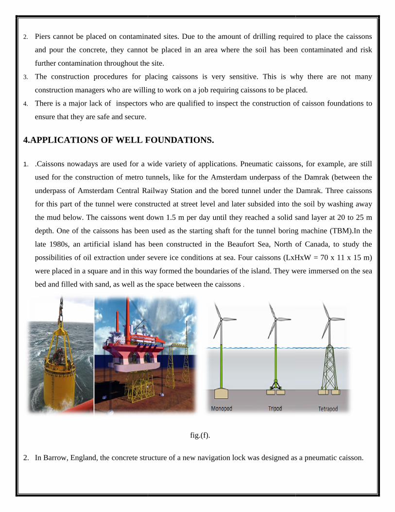
1. .Caissons nowadays are used for a wide variety of applications. Pneumatic caissons, for example, are still
used for the construction of metro tunnels, like for the Amsterdam underpass of the Damrak (between the
underpass of Amsterdam Central Railway Station and the bored tunnel under the Damrak. Three caissons
for this part of the tunnel were constructed at street level an
the mud below. The caissons went down 1.5 m per day until they reached a solid sand layer at 20 to 25 m
depth. One of the caissons has been used as the starting shaft for the tunnel boring machine (TBM).In the
late 1980s, an artificial island has been constructed in the Beaufort Sea, North of Canada, to study the
possibilities of oil extraction under severe ice conditions at sea. Four caissons (LxHxW = 70 x 11 x 15 m)
were placed in a square and in this way for
bed and filled with sand, as well as the space between the caissons
2. In Barrow, England, the concrete structure of a new navigation lock was designed as a pneumatic caisson.
Piers cannot be placed on contaminated sites. Due to the amount of drilling required to place the caissons
and pour the concrete, they cannot be placed in an area where the soil has been contaminated and risk
throughout the site.
The construction procedures for placing caissons is very sensitive. This is why there are not many
construction managers who are willing to work on a job requiring caissons to be placed.
inspectors who are qualified to inspect the construction of caisson foundations to
APPLICATIONS OF WELL FOUNDATIONS.
Caissons nowadays are used for a wide variety of applications. Pneumatic caissons, for example, are still
construction of metro tunnels, like for the Amsterdam underpass of the Damrak (between the
underpass of Amsterdam Central Railway Station and the bored tunnel under the Damrak. Three caissons
for this part of the tunnel were constructed at street level and later subsided into the soil by washing away
the mud below. The caissons went down 1.5 m per day until they reached a solid sand layer at 20 to 25 m
depth. One of the caissons has been used as the starting shaft for the tunnel boring machine (TBM).In the
late 1980s, an artificial island has been constructed in the Beaufort Sea, North of Canada, to study the
possibilities of oil extraction under severe ice conditions at sea. Four caissons (LxHxW = 70 x 11 x 15 m)
were placed in a square and in this way formed the boundaries of the island. They were immersed on the sea
bed and filled with sand, as well as the space between the caissons .
fig.(f).
concrete structure of a new navigation lock was designed as a pneumatic caisson.
Piers cannot be placed on contaminated sites. Due to the amount of drilling required to place the caissons
and pour the concrete, they cannot be placed in an area where the soil has been contaminated and risk
The construction procedures for placing caissons is very sensitive. This is why there are not many
construction managers who are willing to work on a job requiring caissons to be placed.
lified to inspect the construction of caisson foundations to
Caissons nowadays are used for a wide variety of applications. Pneumatic caissons, for example, are still
construction of metro tunnels, like for the Amsterdam underpass of the Damrak (between the
underpass of Amsterdam Central Railway Station and the bored tunnel under the Damrak. Three caissons
d later subsided into the soil by washing away
the mud below. The caissons went down 1.5 m per day until they reached a solid sand layer at 20 to 25 m
depth. One of the caissons has been used as the starting shaft for the tunnel boring machine (TBM).In the
late 1980s, an artificial island has been constructed in the Beaufort Sea, North of Canada, to study the
possibilities of oil extraction under severe ice conditions at sea. Four caissons (LxHxW = 70 x 11 x 15 m)
med the boundaries of the island. They were immersed on the sea
concrete structure of a new navigation lock was designed as a pneumatic caisson.

3. The shipyard of Barrow built ever bigger submarines, which required the construction of a bigger lock. This
was carried out in 1989-1991 by Ballast Nedam. The new navigation lock exists of a U-shaped concrete
caisson, 50 x 50 x 26 m, with a steel gate. The lock stability is guaranteed by a floor thickness of 9 meters.
4. Monitoring during immersion, especially of groundwater, helped to prevent damage to existing structures.
Shutters of 16 meters height retained soil and water during the immersion of the caisson .
5. In Monaco, a floating breakwater has been constructed for the extension of the harbour. The main caisson
has been built in Algeciras, Spain (near Gibraltar) from where it was towed to Monte Carlo, Monaco. This
prestressed caisson has a length of 352 meters, is 28 meters wide, has a height of 19 meters and weighs
160000 tonnes (1.6·106 kN). It is anchored to a steady platform by an abutment caisson. An enormous steel
balland-socket joint attaches the caisson to the land based abutment caisson . This steel articulation is
specially designed to allow rotation and to resist loads up to 100 000 kN. The offshore end of the floating
caisson is anchored by two sets of fixed anchors in water depths of over 55 meters . Besides its primary
function, the breakwater provides berthing space for liners on the sea and harbour side. For about half its
length, the caisson provides parking for 360 cars on precast floors on four levels (inside the box) and the
other half contains two floors of boat stores. In Australia, caissons are used to accommodate turbines to
obtain electric power from tidal currents in sea, For the port of Tangiers, Morocco, about forty-four
cylindrical caissons were use to construct a breakwater
6. Their final height is 35 meters, weighing 7 900 tonnes each. The shape of the caissons is rounded to
reduce wave forces. To prevent ingress of chloride ions and to reduce cracking, a special concrete quality
has been developed. The service lifetime of the breakwater is 100 years.
7. The high speed railroad bridge over the Holland Deep waterway (Netherlands, constructed around 2005) is
two kilometers long, of which 1200 meters is over water. The bridge is supported by eleven piers and two
abutments. This bridge is a composite type bridge made of steel and concrete, necessary to obtain extreme
rigidity, due to the vibrations caused by the passing high speed trains. The bridge pier foundation consists of
driven steel tubes. These tubes are 19 to 33.5 metres long and have a diameter of 3 m. The wall thickness of
the tube varies between 35 and 45 millimetres. After piling, concrete caissons of 10 x 25 x 2.65 metres were
placed above the piles. The bottom of the caissons has holes in it, sealed with steel plates. The holes exactly
match the position of the foundation tubes. The caissons were immersed in such a way that the holes ended
up on top of the piles. After removing the steel plates, 12.5 m long steel meshes were placed in the
remaining holes, followed by a replenishing with underwater concrete. Later, when the concrete had
hardened, the caissons were immovably connected with the steel tubes. During construction, watertight
partitions were put on the walls of the caissons. After immersion of the caissons, these partitions still
protruded far above the water surface. In this way, construction pits were created. These were dewatered for
further construction work.
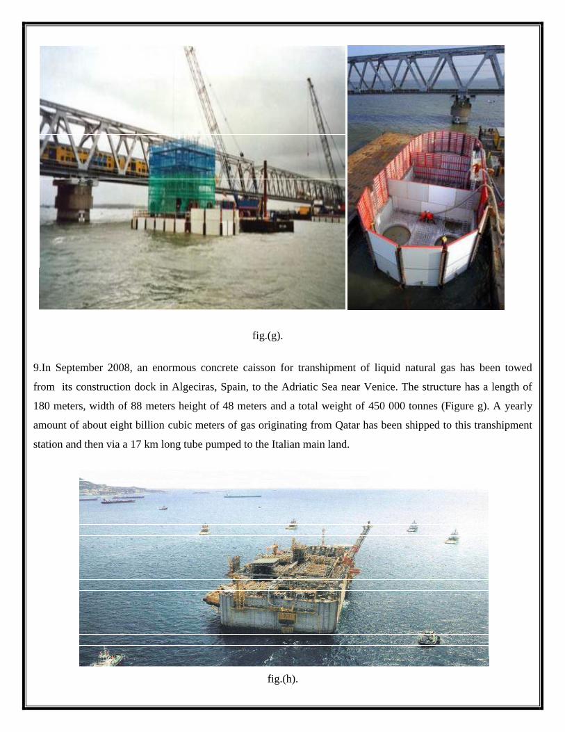
fig.(g).
9.In September 2008, an enormous concrete caisson for transhipment of liquid natural gas has been towed
from its construction dock in Algeciras, Spain, to the Adriatic Sea near Venice. The structure has a length of
180 meters, width of 88 meters height of 48 meters and a total weight of 450 000 tonnes (Figure g). A yearly
amount of about eight billion cubic meters of gas originating from Qatar has been shipped to this transhipment
station and then via a 17 km long tube pumped to the Italian main land.
fig.(h).

Undoubtedly well foundation will continue to prove their value as (part of) solutions for many structural
problems in the future.
CONCLUSION:-
In this study, it is concluded that Caissons or well foundations provide an alternative means to
achieve adequate founding at intermediate to significant depths in both land and water environments. Therefore,
caissons serve a wide variety of purposes in bridge, quay, lock head, breakwater or many other projects.
This form of foundation construction is subject to various degrees of financial, technical and
physical risk because of the uncertainties and arising from deep foundations in ground conditions which can be
highly variable and environments which often have high water tables or are subject to flooding.
Referance:-
M.N.Som,S.C.Das,"Theory and practice of foundation design" , Ashok.k.Ghosh,New Delhi,2006.
P.C.Varghese,"Foundation Engineering", Ashok.k.Ghosh,New Delhi,2005.
Bowles, J.E. ,"Foundation Analysis And Design"(International Student Edition) ,Mc-Greww
hill,Singapore,1988.
Saha G.P. “Analysis and Design of Varanasi Bridge Well Foundations – A Conceptual Approach”, Journal
of Indian Roads Congress Vol. 54-2, Paper presented in the Annual Session of IRC in November 1993.
Dhiman RK , “Well foundation construction in bouldery bed - A case study”,international association of
bridges and structural engineers (IABSE),Punjab,1999.
Dr.Priti Maheshwari , “NPTEL”,IIT Roorkee , http://nptel.ac.in
Dr.Kousik.Deb,“Myopencoures”,IIT Kharaghpur,http://myopencourses.com/video/well-foundation
Wikipedia,http://en.wikipedia.org/wiki/Caisson.

Well Foundation Construction In Bouldery Bed Strata
Summary.
Bridge construction in bouldery bed poses challenge for engineers firstly due to difficulties in
finalization of design depth of foundation due to lack of reliable formulas in present literatures
construction stage due to difficulties in sinking
the soil strata underneath is of heterogeneous character.
well foundation due to mismatch of soil strata anticipated by SS1 and actually
grabbing ,diving and pneumatic sinking is required at various location to sink the well to desired level.
study of well foundation construction in bouldery bed has been discussed in this paper.
Case Study
on
Well Foundation Construction In Bouldery Bed Strata
construction in bouldery bed poses challenge for engineers firstly due to difficulties in
finalization of design depth of foundation due to lack of reliable formulas in present literatures
construction stage due to difficulties in sinking of well foundation even with the use of pneumatic technique as
the soil strata underneath is of heterogeneous character. Construction problems faced specially during sinking of
well foundation due to mismatch of soil strata anticipated by SS1 and actually encountered at site.
,diving and pneumatic sinking is required at various location to sink the well to desired level.
construction in bouldery bed has been discussed in this paper.
Well Foundation Construction In Bouldery Bed Strata
construction in bouldery bed poses challenge for engineers firstly due to difficulties in
finalization of design depth of foundation due to lack of reliable formulas in present literatures ,secondly during
of well foundation even with the use of pneumatic technique as
Construction problems faced specially during sinking of
encountered at site. Open
,diving and pneumatic sinking is required at various location to sink the well to desired level. A case

Introduction.
1. Bridge Construction in bouldery bed strata poses a challenge for the engineers for two basic reasons.
a. Due to non-availibility of a proper formulae to calculate the scour depth.
b. Due to difficulties in construction while executing the work.
2. Most of the long span bridges are on well foundation specially ,where there is a transition
of the river from the hill areas to the plains.Sinking of a well in such strata imoedes the progress of
execution due to the heterogeneous character of the soil and also due to the presence of large size boulders
and wooden logs in the soil strata.A case study of well foundation construction in bouldery bed strata has
been discussed in this paper.
Case Study.
A case study of well foundation execution of a major permanent bridge over a perennial river on
bouldery bed strata is now discussed. The foundation depth of this bridge was more and overall perspective of
well sinking in this case was a difficult one. The subsoil consisted of large boulders of 2 to 3 mtrs.in diameter in
the upper strata, to a depth of about 25 mtrs. and below that the soil was of silt sand aggregate matrix.In the
initial stage, Open grabbing with a crane-grab was resorted to for a depth of about 12 mtrs.and subsequently the
rate of sinking was 10to 20 mm per day .to expedite the progress pneumatic sinking was adopted which led to
increase in the progress to150-900mm.Pneumatic sinking can only be used up to a pressure of 3.50 kg/cm2 .It is
difficult for a human being to work beyond this pressure as per codal provisions.
Important Features Of The Bridge.
Length of the bridge - 704 mts.
Foundation:-
Type -Circular Well.
Outer Diameter -11.7 mtrs.
Inner Dia. -6.64 mtrs
Steining thickness -2.53 mtrs.
Well curb height -4.5 mtrs.
Angle of cutting edge -33 degrees.
Grade for steining concre
Set up of equipment and plant.
The layout ensured minimum movement of material,equipment and personnel as well as proper drainage of
the area .
Wind conditions were taken into considerations in operation of some equipment for example,the operations
of the tower crane which was not possible in heavy winds
Supporting facilities such as generators ,office stores etc.,were located away from the path
Adequate space was provided for handling and storage of raw materials as well as for finished products.
wherever practicable,a separate service road was provided for incoming material and outgoing products.
.
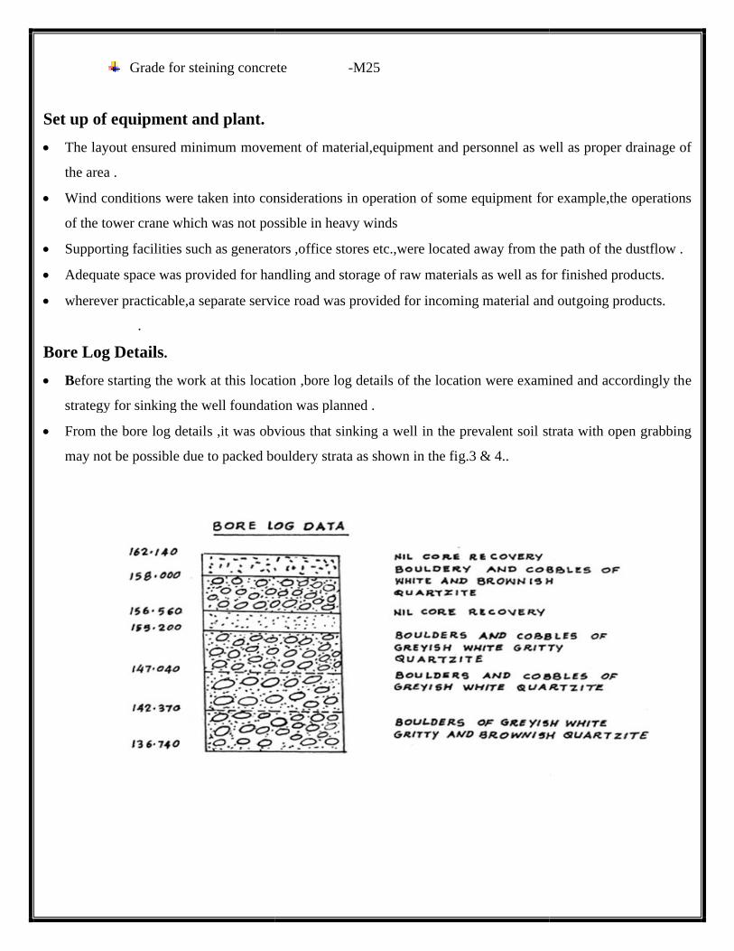
Bore Log Details.
Before starting the work at this location ,bore log details of the location were examined and accordingly the
strategy for sinking the well foundation was planned .
From the bore log details ,it was obvious that sinking a well in the prevalent soil strata with open g
may not be possible due to packed bouldery strata as shown in the fig.3 & 4..
ete -M25
layout ensured minimum movement of material,equipment and personnel as well as proper drainage of
Wind conditions were taken into considerations in operation of some equipment for example,the operations
of the tower crane which was not possible in heavy winds
Supporting facilities such as generators ,office stores etc.,were located away from the path
Adequate space was provided for handling and storage of raw materials as well as for finished products.
wherever practicable,a separate service road was provided for incoming material and outgoing products.
ting the work at this location ,bore log details of the location were examined and accordingly the
strategy for sinking the well foundation was planned .
From the bore log details ,it was obvious that sinking a well in the prevalent soil strata with open g
may not be possible due to packed bouldery strata as shown in the fig.3 & 4..
layout ensured minimum movement of material,equipment and personnel as well as proper drainage of
Wind conditions were taken into considerations in operation of some equipment for example,the operations
Supporting facilities such as generators ,office stores etc.,were located away from the path of the dustflow .
Adequate space was provided for handling and storage of raw materials as well as for finished products.
wherever practicable,a separate service road was provided for incoming material and outgoing products.
ting the work at this location ,bore log details of the location were examined and accordingly the
From the bore log details ,it was obvious that sinking a well in the prevalent soil strata with open grabbing
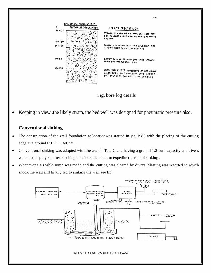
Keeping in view ,the likely strata,
Conventional sinking.
The construction of the well foundation at locationwas started in jan 1980 with the placing of the cutting
edge at a ground R.L OF 160.735.
Conventional sinking was adopted with the use of Tata Crane having a grab of 1.2 cum capacity and divers
were also deployed ,after reaching considerable depth to expedite the rate
Whenever a sizeable sump was made and the cutting was cleared by divers ,blasting was resorted to which
shook the well and finally led to sinking the well.see fig
Fig. bore log details
eeping in view ,the likely strata, the bed well was designed for pneumatic pressure also.
well foundation at locationwas started in jan 1980 with the placing of the cutting
Conventional sinking was adopted with the use of Tata Crane having a grab of 1.2 cum capacity and divers
considerable depth to expedite the rate of sinking .
Whenever a sizeable sump was made and the cutting was cleared by divers ,blasting was resorted to which
shook the well and finally led to sinking the well.see fig.
the bed well was designed for pneumatic pressure also.
well foundation at locationwas started in jan 1980 with the placing of the cutting
Conventional sinking was adopted with the use of Tata Crane having a grab of 1.2 cum capacity and divers
of sinking .
Whenever a sizeable sump was made and the cutting was cleared by divers ,blasting was resorted to which

This work was continued till June 90
approximately 7 cms per day. But the rate of sinking during the last month before suspending conventional
sinking was 1 cm.
It was felt that the further rate of sinking would be extremely slow
pneumatic sinking .
Pneumatic sinking.
Pneumatic sinking was attempted wef 4th J
The steel diaphragm was placed at a gauge height
foundation level of 125mtrs.
During the course of sinking ,boulders upto
sinking ,as boulders more than 50cms size could not be taken out because of the limitation of the muck bucket.
une 90 and an average rate of sinking observed during the period was
But the rate of sinking during the last month before suspending conventional
It was felt that the further rate of sinking would be extremely slow and it was decided to start with
s attempted wef 4th July 1990 at am and RL of 145.360 mtrs.
The steel diaphragm was placed at a gauge height of 14mtrs.THis technique was continued upto a design
,boulders upto 2mtrs size were encountered which slowed down the rate of
,as boulders more than 50cms size could not be taken out because of the limitation of the muck bucket.
and an average rate of sinking observed during the period was
But the rate of sinking during the last month before suspending conventional
and it was decided to start with
of 14mtrs.THis technique was continued upto a design
re encountered which slowed down the rate of
,as boulders more than 50cms size could not be taken out because of the limitation of the muck bucket.

There was also a variation in the water level of the river from 153.5mtrs to 163mtrs during the year .It was
obvious that the deeper the digging, greater was the pressure and progress reduced considerably which further
led to increase in compression and decompression time. however limited progress was assured in the technique
out of a total sinking of 35.89mtrs, 15.35mtrs was executed through conventional means and the remaining
20.3mtrs was by pneumatic sinking. The output of sinking depends upon various factors which include the size
of the bucket, the depth of the well, the type of strata, the water head, the size of the shaft and the air lock. The
team of personnel inside the working chamber comprised of one engineer, two supervisor and 20 labourers. one
mtr of sinking resulted in required 1/10th m3 of material to be evacuated, which in tuen required 440 buckets of
dredging out the material, as the capacity of one bucket was 0.25 m3. the progress of work reduced with the
depth of sinking. however, a percentage of acceptable progress was achieved within a specified time. The rate
of sinking reduced with progressive sinking, as, at an increased pressure, the progress of sinking reduced.
Sr.no. Total sinking achieved in mtrs Average rate of sinking per day
1 Conventional sinking: 15.35mtrs 7cms
2 Pneumatic sinking: 20.45mtrs 4cms
Total sinking: 35.8mtrs
Bottom Plug.
The total sinking of 35.8mtrs was completed and the position of the well was as under:
a. Total steining from ground level - 35.8mtrs
b. Total steining cast -27mtrs
c. Well curb height -4.5mtrs
d. Gauge height of well -31/430mtrs
The last leg of sinking was completed in pneumatic sinking and it was planned to plug the well in the
present condition only, as this would be helpful to remove the steel diaphragm placed inside over working
chamber. The concrete was transported to the air lock and subsequently to the working chamber, where it
formed a part of the bottom plug. this process was repeated a number of times, as in one operation only 1m3 of
concrete was possible. out of total height of 5mtrs, 2mtrs was completed in pneumatic condition and the
remaining was executed in open condition after removing the diaphragm.
Sand filling:
Sand was taken from the river and cleaned before transportation this was finally lowered through a chute
placed on the top of the steining and subsequently the top plug and the well cap were cast.

Construction Problems:
The following problems were encountered during the construction of bridge:
a. The sinking of the well became very difficult due to the presence of large size of boulders in the strata. this
led to a considerable slow down in the overall progress of the bridge
b. Basically there were difficulties in finally deciding the foundation level on such strata. This put the decision
making body into a considerable dilemma and led to delay in progress.
c. Due to heavy rainfall in the area a considerably reduced working period was available in the region, which
led to delay in overall completion of activities.
Conclusion:
Construction of a well foundation in bouldery bed strata calls for a dedicated effort on the part of the
executives.
The data of the soil strata encountered at the site must be kept in detail for each meter and if required a
review of the foundation must be carried out , based on actual soil parameters obtained during sinking.

.