Well Control Manual - Bharat...
47
Well Control Manual Bharat PetroResources Limited BLOCK: CB-ONN-2010/8 GUJRAT-INDIA Prepared By: EnQuest PetroSloutions Pvt. Ltd.
Transcript of Well Control Manual - Bharat...

Well Control
Manual
Bharat PetroResources Limited
BLOCK: CB-ONN-2010/8
GUJRAT-INDIA
Prepared By:
EnQuest PetroSloutions Pvt. Ltd.

WELL CONTROL MANUAL
2
Contents
1.0.0 Definitions
2.0.0. Causes of Kicks
3.0.0. Kick indications
4.0.0. Kick while Tripping
5.0.0. Trip margin
6.0.0. Slow circulating rate
7.0.0. Line up for shut in
8.0.0 Shut in pressures interpretation
9.0.0. Equipment and Instrumentation
10.0.0 Well killing procedure
10.0.2 Driller’s method
10.0.3 Wait and Weight method
10.0.4 Volumetric method
11.0.0 Well control Complications
12.0.0 Special techniques in well control
WELL CONTROL MANUAL
3
1.0.0 Definitions
1.0.1 Influx
The flow of fluids from bottom into the well bore.
1.0.2 Kick
Any influx or flow of formation fluid into the well-bore is termed as Kick. It
may occur any time during drilling/ initial testing or work-over operation due
to formation fluid pressure being greater than the bottom hole pressure.
1.0.3 Blowout
If the kick is uncontrolled, the formation fluid will flow to the surface is termed
as Blow-out.
1.0.4 Pore Pressure
Pore Pressure is the pressure acting on the fluids in the pore spaces in the
rock, is known as Formation pressure also. This is the portion of the
overburden supported by the formation fluid.
1.0.5 Hydrostatic pressure
Pressure exerted by the fluid column at a certain depth is termed as
Hydrostatic Pressure.
1.0.6 Bottom hole pressure (BHP)
Sum of all pressures that are being exerted at the bottom of the hole and
can be written as: BHP = Static pressure + Dynamic pressure
1.0.7 Fracture Pressure
The pressure required to initiate a fracture in a sub surface formation.
Fracture pressure can be determined by Geo-physical methods; during
drilling fracture pressure can be determined by conducting a leak-off test.
1.0.8 Kill Rate
Kill rate is reduced circulating rate that is required when circulating out kicks,
so that additional pressure to prevent formation flow can be added without
exceeding pump liner rating. Kill rate is normally ½ to 1/3 of the normal
circulating rate.
1.0.9 Kill rate pressure
WELL CONTROL MANUAL
4
The pressure measured at drill pipe gauge when the mud pumps are
operating at kill rate.
1.0.10 Maximum allowable annular Surface pressure (MAASP)
It is maximum allowable surface pressure during well control. Any pressure
above this may damage the formation/ casing.
1.0.11 Primary well control
Primary well control is the use of drilling fluid density to provide sufficient
pressure to prevent the influx of formation fluid into the wellbore.
It is of the utmost importance to ensure that primary well control is
maintained at all times. This involves the following:
a. Drilling fluids of adequate density are used.
b. Well is kept full of adequate density fluid at all times.
c. Active volumes are continuously monitored, especially during tripping.
d. Changes in density, volumes and flow rate of drilling fluids from the
wellbore are immediately detected and appropriate action taken..
1.0.12 Secondary well control
Secondary Control is the proper use of blowout prevention equipment to
control the well in the event that primary control cannot be properly
maintained. Early recognition of warning signals and rapid shut-in are the
key to effective well control. By taking action quickly, the amount of
formation fluid that enters the welIbore and the amount of drilling fluid
expelled from the annulus is minimized. The size and severity of a
kickdepends upon:
e. The degree of underbalance.
f. The formation permeability.
g. The length of time the well remains underbalanced.
Smaller kicks provide lower choke or annulus pressure both upon initial
closure and later when the kick is circulated to the choke.

WELL CONTROL MANUAL
5
1.0.13 Tertiary Well Control:
Tertiary well control describes the third line of defence. Where the
formationcannot be controlled by primary or secondary well control
(hydrostatic and equipment). In the event that secondary control cannot be
properly maintained due to hole conditions or equipment failure,certain
emergency procedures can be implemented to prevent the loss of control.
These procedures are referred to as "Tertiary Control" and usually lead to
partial or complete abandonment of the well. Unlike primary and secondary
control, there are no established tertiary well control procedures that will
work in most situations. The procedures to be applied depends on the
particular operating conditions which are encountered, and specific
recommendations regarding appropriate tertiary control procedures cannot
be given until the circumstances leading to the loss of secondary control are
established.
An underground blowout for example. However in well control it isnot always
used as a qualitative term. ‘Unusual well control operations’ listed below are
considered under this term:-
a) A kick is taken with the string off bottom.
b) The drill pipe plugs off during a kill operation.
c) There is no pipe in the hole.
d) Hole in drill string.
e) Lost circulation.
f) Excessive casing pressure.
g) Plugged and stuck off bottom.
h) Gas percolation without gas expansion.
We could also include operations like stripping or snubbing in the hole, or
drillingrelief wells. The point to remember is "what is the well status at shut
in?" This determines the method of well control. However, there are two
procedures that are widely used. These involve the use of:
WELL CONTROL MANUAL
6
- Barite plugs
- Cement plugs
1.0.14 Accumulator (BOP Control Unit)
A pressure vessel charged with Nitrogen or other inert gas and used to store
hydraulic fluid under pressure for operation of blowout preventers and/or
diverter system.
1.0.15 Annular Preventer
A device which can seal around different sizes and shapes object in the well
bore or seal an open hole.
1.0.16 Blowout Preventer Stack
The assembly of well control equipment including preventers, spools, valves
and nipples connected to the top of the casing head
1.0.16 Choke manifold
The assembly of valves, chokes, gauges and piping to control flow from the
annulus and regulate pressure in the drill string/ annulus when the BOPs are
closed.
1.0.17 Degasser
A vessel, which utilizes pressure reduction and/or inertia to separate
entrained gasses from the liquid phases.
1.0.18 Diverter
A device attached to the well head to close the vertical excess and direct
flow into a line away from the rig.
1.0.19 Mud gas separator
a device that removes gas from the returned drilling fluid, when a kick is
being circulated out. It is also known as gas buster or poor boy degasser.
1.0.20 Kick tolerance:
Kick tolerance is the volume of the kick at a given pressure which can be
safely shut in and circulated out of the well without fracturing the formation.
1.0.21 Underbalanced Drilling (UBD)

WELL CONTROL MANUAL
7
Is a drilling process when the hydrostatic head of the drilling fluid has to be
kept lower than the formation pressure, with the intention of bringing
formation fluid to the surface. It is necessary when formation pressure is
sub-hydrostatic and there are every chances of loss circulation, if otherwise
drilled with normal drilling fluid. The hydrostatic pressure is maintained by
adding natural gas, nitrogen or air to the drilling fluid so that hydrostatic
pressure of drilling fluid is lower than the formation pressure.
2.0.0. Causes of kicks
Kicks occur as a result of formation pressure being greater than mud
hydrostatic pressure that causes flow of formation fluid into the well bore.
The main factors which can lead to this condition can be classified as :
a) Human error
b) Improper hole fill up on trips.
c) Swabbing.
d) Abnormal formation pressure.
e) Insufficient mud density.
f) Lost circulation
g) Gas cut mud
Note; More than 50% of the kicks occur due to first three of the causes listed
above.
2.0.1. Improper hole fill up on trips
When the drill string is pulled out, the mud level decreases by a volume
equivalent to the steel volume. If the hole does not take the calculated
volume of mud, it is assumed a formation fluid has entered the wellbore.
This can be ascertained by using Trip Tank during filling up the hole and
differences of calculated and actual mud volume be recorded at regular

WELL CONTROL MANUAL
8
intervals. Similarly while running in drill string, trip tank should be used to
monitor displacement volume correctly at regular intervals.
If the hole is not filled to replace the steel volume, the fluid column in the
wellbore shall go down and reduce the hydrostatic pressure. At the same
time the pulling out of drill string causes a reduction in BHP due to swabbing
effect. Therefore to avoid the possibility of any formation fluid entering the
bore hole due to combination of above two factors the hole should be
properly / regularly filled during tripping out.
In the field normally the practice is to fill up the hole either on a regular fill up
schedule or to fill up continuously with a re-circulating trip tank. Irrespective
of the practice being used an accurate method of measuring the amount of
fluid actually being taken by hole should be monitored and an accurate
record of actual volume v/s theoretical volume should be kept. If at any
stage during pulling-out it is observed that the actual filled in volume is
significantly less than volume of steel that has been removed, it means that
some formation fluids must have entered the wellbore.
2.0.2. Swabbing
During pulling out the drill string from the borehole, swab pressures are
created, resulting reduction in bottom hole pressure. If, reduced bottom hole
pressure becomes less than the formation pressure, a potential kick may
enter the well bore. Various factors conducive to swab pressures are speed
of pulling out, mud properties, filtration cake, annular clearance, hole
configuration and effect of balling up of BHA & bit.
2.0.3. Abnormal pressure
Formation pressures are not known precisely while drilling wild cat or
exploratory wells. Sometimes the bit suddenly penetrates an abnormal
pressure formation. As a result the mud hydrostatic pressure becomes less

WELL CONTROL MANUAL
9
than the formation pressure and may cause a well kick. There are various
geological reasons for abnormal pressures.
2.0.4. Insufficient mud density
If a formation is drilled using a mud density that exerts less hydrostatic
pressure than the pore pressure, the formation fluid may begin to flow into
the well bore. Kicks caused by insufficient mud density can be resolved by
drilling with high mud density.
2.0.5. Lost circulation
Another factor, which reduces the hydrostatic pressure, which is matter of
concern, is lost circulation. The problem may become more severe, when a
kick occurs due to lost circulation. A large volume of kick fluid may enter the
hole before the mud level increase is observed at the surface. It is a
recommended practice to keep the annulus always topped to avoid
considerable reduction in BHP when lost circulation is encountered.
2.0.6. Gas cut mud
Gas cut mud may occasionally cause a kick. As the gas is circulated to the
surface, it expands and reduces the hydrostatic pressure sufficient to allow a
kick to enter. Fortunately, the mud density is reduced considerably at the
surface due to gas expansion takes place near surface, resulting hydrostatic
pressure is not reduced significantly.
3.0.0 Kick indication
Following are the early warning signs & positive indications for kicks while
drilling.

WELL CONTROL MANUAL
10
3.0.1 Early warning signs
The early warning signs are indications of approaching higher formation
pressure which means that the well may go under-balance if no appropriate
action is taken. These are as listed below :
i). Drilling Break
The first indication of a possible well kick is a drilling break. There should be
a permeable section of reservoir rock for reservoir fluid to enter the well
bore. In soft formation, a sand section usually causes a sudden increase in
drilling rate. The increase in drilling rate varies.
ii). Rate of Penetration (ROP)
A gradual increase in ROP may be an indication of entering abnormal
pressure formations. Similarly weight on bit also changes which can be
detected by careful observation.
iii). Change in Cutting Size and Shapes
Cuttings from normal pressure shale are smaller in size with rounded edges
and are generally flat. Cuttings drilled from abnormal pressured formation
often become long and splintery with angular edges. As differential pressure
is reduced due to increase in formation pressure, the cuttings have a
tendency to explode off bottom. A change in cutting shape will be observed
along with an increase in the amount of cuttings recovered at the surface
and this could indicate that formation pressure in the well is increasing.
iv). Increase in hook load
Displacement of drilling fluid by influx will reduce the buoyancy of the drilling
fluid, resulting in increase in hook load. However, by the time the change in
hook load is noticed, a considerable will already have been taken.

WELL CONTROL MANUAL
11
v). Increase in Torque & Drag
The larger cuttings, caused due to above, are piled up around the collars
and increase the rotary torque. Increase in rotary torque is a good indication
of increasing formation pressure and a potential well kick. Drag & fill up on
connections and trips increase when high pressure formations are drilled.
vi). Decrease in Shale Density
Shale density usually increases with depth but decreases in abnormal
pressure zones. The density of cuttings can be determined at surface and
plotted against depth. A normal trend line is established and any deviation
should theoretically indicate changes in pore pressure.
vii). Increase in Chloride Content in Mud Filtrate
Contamination of drilling fluid with considerable volume of saline water from
pores may takes place while drilling through high pressure formations. This
increases chloride content of the drilling fluid and its filtrate. A higher
chloride trend can warn about increase in pore pressure.
viii). Change in Mud Property
As the pressure in the formation increases faster than the mud hydrostatic,
more cuttings & caving will dissolve into the mud and increase the viscosity
of the mud. Higher changes in mud density trend may warn increase in pore
pressure.
ix). Increase in Flow Line Temperature
Increase in Flow Line Temperature also indicates in formation pressure. The
temperature gradient in abnormal pressure formation is usually higher than
normal formation. The continuous measurement of the mud temperature at

WELL CONTROL MANUAL
12
the flow line gives an indication of change in temperature gradient
associated with abnormally pressured formation. The temperature may take
a sharp increase in transition zones.
x). Incorrect fill up volume on a trip
Most kicks occur while tripping. Hole fill up volume on a trip must be
monitored carefully and a trip sheet filled out.
xi). Gas cut mud
If a small influx is taken and no pit volume is detectable, the first indication
that a kick has occurred may be gas-cut mud at the flow line. However, this
may not be conclusive as gas may be from drilled cuttings also.
xii). Change in ‘d’-exponent
Jordan and Shirley developed an equation for normalized penetration rate in
which it was defined as a function of measured drilling rate, weight on bit, bit
size and rotary speed in the equation as below:
d = log (R/60N)/log (12W/103 Db)
Where,
R = rate of penetration in ft/hr
N = rotary speed rpm
W = weight on bit in 1000 lbs
Db = bit diameter in inches
Since the d-exponent tends to indicate the pressure differential between
formation pressure and well bore pressure, mud weight will effect d -
exponent. The original calculation should be corrected as follows:
where,
dc = modified d-exponent

WELL CONTROL MANUAL
13
MW1 = mud density equivalent of formation fluid at normal pressure
condition
MW2 = mud density being used in well
dc values are plotted on a semi log graph paper at every 15 or 30 ft. interval
depth to give normal trend line. Abnormal pressure transition zone top is
detected at the depth where dc exponent values against shale tend to
decrease in comparison to normal values.
3.0.2 Positive Kick Sign
Positive kick indicators are different from kick warning signs. They indicate
that the kick has already entered the well bore. Any of them indicate regular
flow checks.
a) Increase in Return Flow (Pumps On)
After the early warning signs the first positive kick sign is increase in flow
rate at the flow line with pumps on. Increase in flow rate indicates entrance
of any fluid into the well bore.
b) Flow from Well (Pumps Off)
Flow check is a reliable method of checking for a well kick by stopping the
pump. If the well does not flow when the pump is shut off and remains static
for two or three minutes, then no well kick takes place.
c) Increase in Pit Volume
An increase in pit volume is obvious & positive indication of flow into the well
bore. If an increase in pit volume is observed, shut off the pump and make a
flow check which confirms if kick is entering.
d) Decrease in Pump Pressure and Increase in Pump Stroke
In case of kick there is under balanced condition between the fluid in the drill
pipe and the mixed column of mud and influx in the annulus. Therefore
WELL CONTROL MANUAL
14
circulating pressure gradually decreases at constant pump throttle, and
pump speed slowly increases.
4.0.0. Kick while tripping
The basic requirement to prevent kick while tripping, is that hole must be
kept full of mud and the volume of mud required to fill the hole must be equal
to the steel displacement of drill string pulled out. The sequence of events to
a kick while making a trip-out of hole is :
4.0.1 Hole does not take proper amount of mud. Whenever such situation is
noticed the pipe should be run back as far as possible to bottom safely and
mud is circulated to clear the hole.
4.0.2 Flow from the flow line
4.0.3 Increase in pit volume
The sequence of events leading to a kick while tripping-in the hole is:
i). The hole does not stop flowing during making connection between the
stands
ii). Increase in pit volume
In order to avoid well kicks while tripping, trip schedule must be made and
trip tank must be used to monitor the hole fill up (in case of tripping-out) and
mud displacement (in case of tripping-in).
5.0.0 Trip margin
During pulling out, upward motion of the drill string in the borehole creates a
swab pressure. This decreases BHP when pipe is in motion. One way of
minimizing this is to use safe tripping speeds and having close monitoring of
pipe volume pulled out & mud volume pumped in to keep the hole full.
Another practice to tackle the problem is to keep mud weight gradient
greater than the formation pressure gradient. The resulting overbalance
permits safe tripping and connection operations. This extra mud weight is

WELL CONTROL MANUAL
15
called trip margin. For normal drilling operation trip margin is kept 0.2 to 0.3
ppg. However, the swab pressure being a function of yield point (yp) of mud,
trip margin can be calculated as follows:-
-Dp)
Where
Yp = Yield point of mud in lbs/100 sq.ft
Dh = Hole diameter in inches
Dp = Pipe outside diameter in inches
6.0.0. Slow circulation rate
During well control operations, to avoid further entry of formation fluid it is
essential to keep BHP minimum equal to formation pressure. This is done by
imposing certain calculated backpressure in addition to system pressure
losses on the well bore as long as old mud is in the well. Kicks have to be
circulated out at slow circulation rates to ensure that the sum of this back
pressure and system losses does not exceed the rating of high pressure
lines and other rig equipment. Various reasons for circulating out the kicks at
slow circulation rates are: -
a) To ensure that the slow circulation pressure plus the shut in drill pipe
pressure is a convenient total pressure for the pump and does not exceed
the surface line ratings.
b) To allow mud returns to be weighted up and re-circulated within the
capabilities of available mud mixing system.
c) To allow longer reaction time for choke adjustments.
d) To allow sufficient time for disposal of kick fluid /de-gassing at the surface.
e) To reduce the annular pressure losses.
Theoretically speaking, the kill rate or slow circulation rate should be the
minimum possible pump speed at which pump can run smoothly without any

WELL CONTROL MANUAL
16
knocking. The widely used common practice, for triplex pump, is between
1/2 to 1/3 of pump SPM at the time of drilling.
6.0.1. Recording of slow circulation rate
It should be recorded near to the bottom for each pump at regular intervals
and / or when drilling conditions change such as:-
i). At the beginning of each shift.
ii). After change in drilling fluid density.
iii). After change in bit nozzle size or BHA.
iv). After drilling a long section of hole (say 500 ft.) in a shift.
v). After pump fluid end repair.
There are a number of places on the rig where drill pipe pressure gauges
are installed such as stand pipe, mud pumps, driller’s console, choke & kill
manifold and remote choke panel. Slow circulation pressure should be
recorded from the gauge that is to be used for well killing operation. So, it
should be recorded at remote choke panel, if available on the rig.
7.0.0. Line up for shut in
When one or more positive kick signs are observed, flow check is made. In
case of self flow well can be shut-in in two ways:
a) Soft shut-in
b) Hard shut-in

WELL CONTROL MANUAL
17
7.0.1. SHUT IN PROCEDURES as per API RP 59
As per following are the shut-in procedures for land/jack-up rigs.
Figure 1: Line up for soft shut-in
Line up for soft shut in:
Choke line manual valve : Open
HCR : Close
Line between HCR & Choke : Open
Remote choke : Open (partially)
Line from choke to MGS : Open

WELL CONTROL MANUAL
18
Figure 2 : Line up for hard shut-in
Line-up for hard shut-in
Choke line manual valve : Open
HCR : Close
Line between HCR & Choke : Open
Remote choke : Close
Line from choke to MGS : Close
7.0.2. While Drilling
1) Stop rotary.
2) Pick up kelly to clear tool joint above rotary table.
3) Stop mud pump, check for self flow. If yes, close the well as follows
WELL CONTROL MANUAL
19
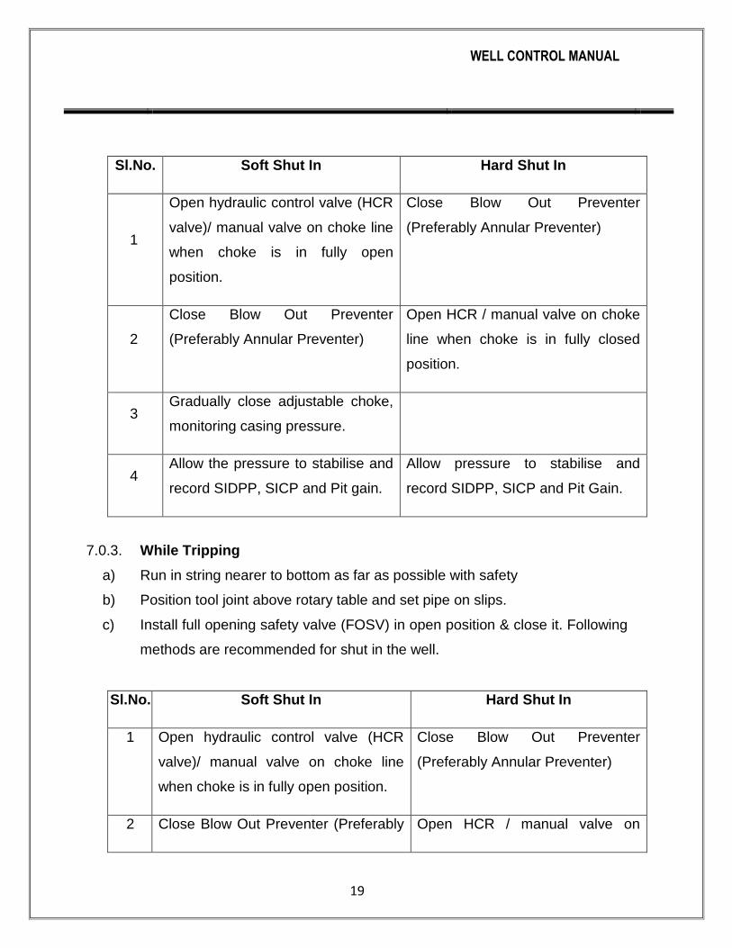
Sl.No. Soft Shut In Hard Shut In
1
Open hydraulic control valve (HCR
valve)/ manual valve on choke line
when choke is in fully open
position.
Close Blow Out Preventer
(Preferably Annular Preventer)
2
Close Blow Out Preventer
(Preferably Annular Preventer)
Open HCR / manual valve on choke
line when choke is in fully closed
position.
3 Gradually close adjustable choke,
monitoring casing pressure.
4 Allow the pressure to stabilise and
record SIDPP, SICP and Pit gain.
Allow pressure to stabilise and
record SIDPP, SICP and Pit Gain.
7.0.3. While Tripping
a) Run in string nearer to bottom as far as possible with safety
b) Position tool joint above rotary table and set pipe on slips.
c) Install full opening safety valve (FOSV) in open position & close it. Following
methods are recommended for shut in the well.
Sl.No. Soft Shut In Hard Shut In
1 Open hydraulic control valve (HCR
valve)/ manual valve on choke line
when choke is in fully open position.
Close Blow Out Preventer
(Preferably Annular Preventer)
2 Close Blow Out Preventer (Preferably Open HCR / manual valve on

WELL CONTROL MANUAL
20
Annular Preventer) choke line when choke is in fully
closed position.
3 Gradually close adjustable choke,
monitoring casing pressure.
4 Make up Kelly and open FOSV Make up Kelly and open FOSV
5 Allow the pressure to stabilise and
record SIDPP, SICP and Pit gain.
Allow pressure to stabilise and
record SIDPP, SICP and Pit Gain.
7.0.4. While String is Out of Hole
Sl.No. Soft Shut In Hard Shut In
1 Open HCR valve on choke line. Close shear or blind ram.
2 Close shear or blind ram. Open HCR valve on choke line.
3 Close choke. Close choke.
4 Record SICP and pit gain. Record SICP and pit gain.
8.0.0. Shut in pressure interpretation
8.0.1 Shut-in Drill Pipe Pressure (SIDPP)
SIDPP is the difference between formation pressure and mud hydrostatic
head when a kick enters the hole. SIDPP is used to determine the kill mud
weight required to balance the formation pressure by using the equation
given below

WELL CONTROL MANUAL
21
The shut in drill pipe pressure should be read & recorded from the gauge on
the choke control panel. Since true SIDPP is determined for the calculation
of kill mud density, it is recommended to read and record the SIDPP
immediately after the closure and subsequently after every 3-5 minutes.
The recorded values of SIDPP should be tabulated/ plotted to ascertain the
true value of SIDPP. Once the well is closed initially the SIDPP starts
increasing till the BHP becomes equal to the formation pressure. The time
taken for stabilization depends upon the permeability of the formation.
SIDPP may further increase but at a slower rate if the influx is gas/gas
mixture.
8.0.2 Shut-in Casing Pressure (SICP)
SICP, the shut in pressure on the annulus side is the difference between the
combined fluid hydrostatic pressures and formation fluid pressure. Since
annulus is contaminated with formation fluid (Oil, gas, salt water or
combinations) therefore SICP can not be used to calculate kill mud density
however it is used to determine kind of influx which has entered the well
bore. During kill operation casing pressure will allow us to determine the
pressure being exerted at various points in the well bore and also pressures
on the BOP equipment and choke lines.
Example
A well was shut in after a kick, given below are the tabulated values of
SIDPP and SICP. Find out the stabilized value of SIDPP.
Time SIDPP(psi) SICP(psi)
0915 150 175
0920 250 295
0925 325 395
0930 380 475

WELL CONTROL MANUAL
22
0935 440 545
0940 445 550
0945 455 560
0950 470 575
0955 490 595
Note : Pressure recording should be done at every two minutes interval.
Solution
As evident from tabulated values, SICP is increasing faster than SIDPP up-
to 0935 hrs but later both the pressures are rising by same amount. This
shows that the pressures have stabilized at 0935 hrs and subsequently due
to close well gas migration both the pressures are rising by same amount.
Therefore the value recorded at 0935 hrs i.e. 440 psi is the true SIDPP. The
proper recognition of stabilized value of SIDPP is very important as this
value is used for the calculation of kill mud weight and formation pressure.
Example
A well was shut in after a kick, given below are the tabulated values of
SIDPP and SICP. Find out the stabilized value of SIDPP.
Time SIDPP(psi) SICP(psi)
1100 100 250
1105 200 370
1110 290 470
1115 370 560
1120 450 650
1125 450 650
1130 450 650
1135 450 650
1140 455 655
66
1145 460 660
1150 465 670

WELL CONTROL MANUAL
23
Solution
As is evident from tabulated values, SIDPP and SICP were increasing
considerably up to 1120 hrs & later there is no change in the pressures up to
1135 hrs Therefore the value recorded at 1120 hrs i.e. 450 psi is the
stabilized value of SIDPP. Further increase in both the pressures is due to
closed well gas migration.
Equipment and Instrumentation
To maintain control of the well when well head pressures develop,
requirements are:
A means of closing the well
A means of pumping into the well and controlling the release of
fluids and gases.
A level of instrumentation, with back up, which will enable
evaluation and monitoring of pressures during this critical operation.
9.0.1 Well heads
Well head provides a means of landing and sealing around casing strings
and supporting the BOP stack. Their pressure integrity is vital to well control,
the rated working pressure exceeding the maximum expected surface
pressure. They must also have sufficient strength to support subsequently
installed casing and tubing strings as well as the BOP stack.
9.0.2 BOP Equipment
BOP must have the capacity to close-in the well, with or without tubular in
the hole and also provide means of stripping in or out of the hole, or
shearing the pipe if necessary.
9.0.2.1 Ram Preventers
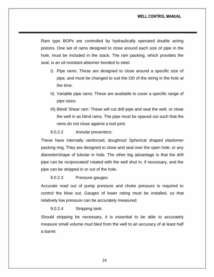
WELL CONTROL MANUAL
24
Ram type BOPs are controlled by hydraulically operated double acting
pistons. One set of rams designed to close around each size of pipe in the
hole, must be included in the stack. The ram packing, which provides the
seal, is an oil resistant alstomer bonded to steel.
I). Pipe rams: These are designed to close around a specific size of
pipe, and must be changed to suit the OD of the string in the hole at
the time.
II). Variable pipe rams: These are available to cover a specific range of
pipe sizes.
III). Blind/ Shear ram: These will cut drill pipe and seal the well, or close
the well in as blind rams. The pipe must be spaced out such that the
rams do not close against a tool joint.
9.0.2.2 Annular preventers:
These have internally rainforced, doughnut/ Spherical shaped elastomer
packing ring. They are designed to close and seal over the open hole, or any
diameter/shape of tubular in hole. The other big advantage is that the drill
pipe can be reciprocated/ rotated with the well shut in, if necessary, and the
pipe can be stripped in or out of the hole.
9.0.2.3 Pressure gauges:
Accurate read out of pump pressure and choke pressure is required to
control the blow out. Gauges of lower rating must be installed, so that
relatively low pressure can be accurately measured.
9.0.2.4 Stripping tank:
Should stripping be necessary, it is essential to be able to accurately
measure small volume mud bled from the well to an accuracy of at least half
a barrel.

WELL CONTROL MANUAL
25
9.0.2.5 Diverter Equipment and Control system Standard RP-174)
A Diverter system is a large, low pressure annular preventer with large
diameter discharge lines to divert well fluids from the rig. If shallow gas is
encountered, it is possible to deplete it through the diverter to provide
sufficient time to evacuate the rig floor. A Diverter system is used during top
hole drilling, where other BOP system can not be used to control shallow
gas. Shutting the well in will cause the formation to break down, with the
possibility of gas blowing up the outside of the casing. It allows routing of the
flow away from the rig to protect persons and equipment. Components of
Diverter system include- annular sealing device, vent outlet, vent lines,
valves and control system.
9.0.3 Recommended practice of Diverter system:
I). The friction loss should not exceed the diverter system rated working
pressure, place undue pressure on the well bore and/or exceed other
equipment’s design pressure etc
II). To minimize back pressure on well bore while diverting well fluids. Diverter
piping should be adequately sized.
III). Vent line shold be 8” or above
IV). Diverter lines should be straight as far as possible, properly anchored and
sloping down to avoid blockage of the lines with cuttings.
V). The diverter and the mud return should be separate lines.
VI). Diverter valves should be full opening type either pneumatic or hydraulic or
mechanical.
VII). The diverter control system may be self contained or integral part of the
BOP control system.
VIII). The diverter control system should be capable of operating from two or more
locations- one to be located near the driller’s console.

WELL CONTROL MANUAL
26
IX). Control system of the diverter should be capable of closing the diverter
within maximum 45 seconds and simultaneously opening of the valves in the
diverter lines.
9.0.4 Procedures for diverter operation:
Where shallow casing strings or conductor pipe are set, fracture
gradientswill be low. It may be impossible to close the BOP on a shallow gas
kick without breaking down the formation at the shoe. If a shallow gas kick
istaken while drilling top hole then the kick should be diverted.Drilling
shallow sand too fast can result in large volumes of gas cut mud inthe
annulus and cause the well to flow, also fast drilling can load up theannulus
increasing the mud density leading to lost circulation and if the levelin
annulus drops far enough then well may flow. When drilling top hole
a diverter should be installed and it is good practiceto leave the diverter
installed until 13 3/8" casing has been run. An automaticdiverter system
should first:-
I). Open an alternative flow path to overboard lines.
II). Close shaker valve and trip tank valve.
III). Close diverter annular around drill pipe.
IV). If there are two overboard lines then the upwind valve should
bemanually closed.
If any indication of flow is observed while drilling top hole, close diverter
immediately as the gas will reach surface in a very short time and it
isinadvisable to attempt a flow check
Suggested diverting procedure in the event of a shallow gas kick.
a) Maintain maximum pump rate and commence pumping
kill mud if available.
b) Space out so that the lower safety valve is above the drill floor.
c) With diverter line open close shaker valve and diverter packer.

WELL CONTROL MANUAL
27
d) Shut down all nonessential equipment, if there is an indication of gas
onrig floor or cellar area then activate deluge systems.
e) On a land rigs monitor area near the cellar and around for evidence of
gas breakingout around conductor.
f) If mud reserves run out then continue pumping with sea-water.
g) While drilling top hole a float should be run. This will prevent
gasentering drill string if a kick is taken while making a connection.
It willalso stop backflow through the drill string on connections.
h) Alert the personnel on the rig.
i) Take all precautions to prevent fire by putting off all naked flames and
unnecessary electrical system.
WELL CONTROL MANUAL
28
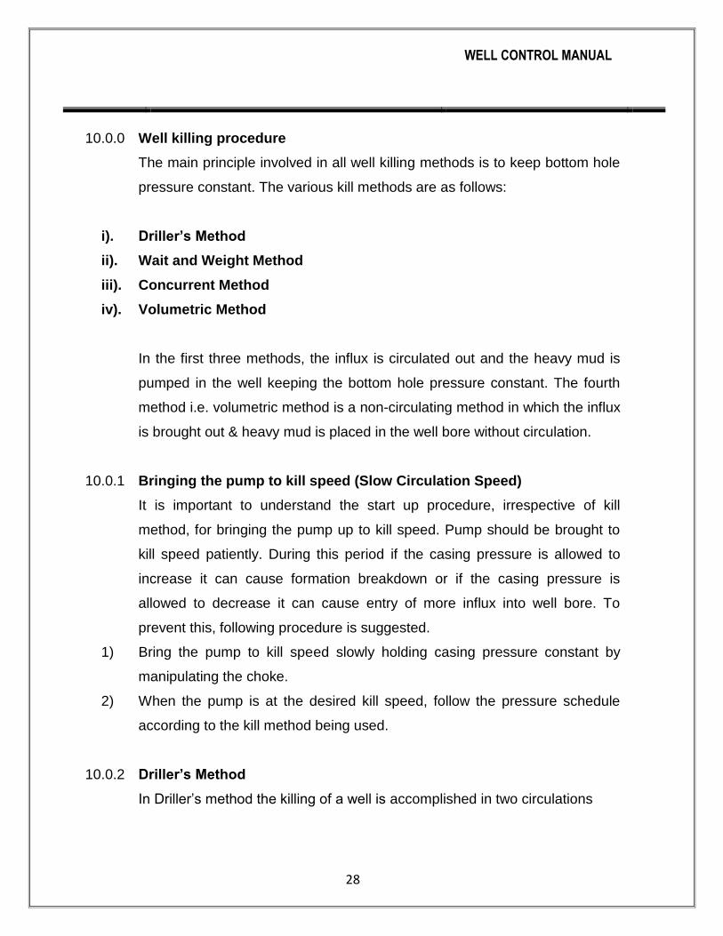
10.0.0 Well killing procedure
The main principle involved in all well killing methods is to keep bottom hole
pressure constant. The various kill methods are as follows:
i). Driller’s Method
ii). Wait and Weight Method
iii). Concurrent Method
iv). Volumetric Method
In the first three methods, the influx is circulated out and the heavy mud is
pumped in the well keeping the bottom hole pressure constant. The fourth
method i.e. volumetric method is a non-circulating method in which the influx
is brought out & heavy mud is placed in the well bore without circulation.
10.0.1 Bringing the pump to kill speed (Slow Circulation Speed)
It is important to understand the start up procedure, irrespective of kill
method, for bringing the pump up to kill speed. Pump should be brought to
kill speed patiently. During this period if the casing pressure is allowed to
increase it can cause formation breakdown or if the casing pressure is
allowed to decrease it can cause entry of more influx into well bore. To
prevent this, following procedure is suggested.
1) Bring the pump to kill speed slowly holding casing pressure constant by
manipulating the choke.
2) When the pump is at the desired kill speed, follow the pressure schedule
according to the kill method being used.
10.0.2 Driller’s Method
In Driller’s method the killing of a well is accomplished in two circulations

WELL CONTROL MANUAL
29
i). In first circulation the influx is removed from the well bore using original mud
density.
ii). In second circulation the kill mud replaces the original mud and restores the
primary control of the well.
Formulae Required
1)
2) Initial Circulating Pressure (ICP) = SIDPP(psi) + SCP (psi)
3)
4) Surface to Bit = Drill string volume (bbl) ÷ Pump output (bbl/stroke
5) Bit to Shoe = Open hole annulus volume (bbl) ÷ Pump output (bbl/stroke)
6) Bit to Surface = Annulus volume (bbl) ÷ Pump output (bbl/stroke)
10.0.2.1 Killing Procedure (Drillers Method)
In this method the well is killed in two circulations.
1) First Circulation
a). Bring the pump up to kill speed in steps of 5 SPM, gradually opening the
choke holding casing pressure constant.
b). When the pump is up to kill speed, maintain drill pipe pressure constant.
c). Circulate out the influx from the well maintaining drill pipe pressure constant.
d). When the influx is out, stop the pump reducing the pump speed in steps of 5
SPM, gradually closing the choke, maintaining casing pressure constant.
Record pressure, SIDPP and SICP should be equal to original SIDPP.
Note : In case recorded SIDPP & SICP are equal but more than original
SIDPP value, it indicates trapped pressure in well bore. Whereas if SICP is
more than original SIDPP, it indicates that some influx is still in the well bore.
2) Second Circulation
a). Line up suction with kill mud.

WELL CONTROL MANUAL
30
b). Bring the pump up to kill speed in steps of 5 SPM, gradually opening the
choke holding casing pressure constant.
c). When the pump is at kill speed, pump kill mud from surface to bit,
maintaining casing pressure const.
d). Pump kill mud from bit to surface, maintaining drill pipe pressure constant
equal to FCP.
e). When the kill mud reaches surface, stop the pump reducing the pump in
steps of 5 SPM, gradually closing the choke maintaining casing pressure
constant. Record pressures, SIDPP and SICP both should be equal to zero.
Open & observe the well. Add trip margin before resuming normal operation.
Pressure Profile- 1st Cycle of Driller’s Method
Pressure profile of drill pipe pressure and casing pressure in first cycle of
Drillers method is given on next page

WELL CONTROL MANUAL
31
Figure 3: Pressure Profile- 1st Cycle of Drillers Method
i). A - B Casing pressure rises as influx expands in drill collar annulus.
ii). B - C Casing pressure decreases as influx crosses over from drill collar
annulus to drill pipe annulus & losses height.
iii). C - D Casing pressure again rises as influx now expands in drill pipeand it
becomes maximum when influx reaches surface at point ‘D’ on the graph.
iv). D - E Casing pressure reduces sharply as influx is removed from the
wellbore.

WELL CONTROL MANUAL
32
Drill Pipe Pressure Graph
i). I - J Drill pipe pressure is held constant till the influx is removed from the well
bore.
Casing Pressure Graph
i). F - G Casing pressure is held constant till kill mud is pumped from surface to
bit.
WELL CONTROL MANUAL
33
ii). G - H Casing pressure reduces to zero as kill mud is pumped from bit to
surface.
Drill Pipe Graph
a). L - M Drill pipe pressure reduces as kill mud is pumped from surface to bit.
During this period SIDPP drops & becomes zero whereas KRP increases to
FCP value. On the whole drill pipe pressure reduces from ICP to FCP.
b). M - N Drill pipe pressure is held constant as the kill mud is pumped from bit
to surface.
10.0.3 Wait and Weight Method
1) In Wait and Weight method well is killed in one circulation using kill mud.
2) In this method, operations are delayed (wait) once the well is shut in, while a
sufficient volume of kill (weight) mud is being prepared. As the kill mud
moves from surface to the bit the hydrostatic pressure in the Drill Pipe
increases, this causes the drill pipe pressure to fall. At the same time, influx
which is on its way up the annulus expands continuously and gains volume /
height, thereby causing the hydrostatic pressure in annulus to fall and casing
pressure to rise. Because of this, for maintaining BHP constant a calculated
step down plan for the drill pipe pressure must be used while pumping the
kill mud from surface to the bit.
Formulae required
i).
ii). Initial Circulating Pressure (ICP) = SIDPP(psi) + KRP (psi)
iii).
iv). Surface to Bit Strokes = Drill string volume (bbl) ÷ Pump output (bbl/stroke)
v). Bit to Shoe Strokes = Open hole annulus volume (bbl) ÷ Pump output
(bbl/stroke)

WELL CONTROL MANUAL
34
vi). Bit to Surface Strokes = Annulus volume (bbl) ÷ Pump output (bbl/stroke)
ICP – FCP v). Pressure drop / 100 strokes = —————————— ×100 Surface to bit strokes
10.0.3.1 Killing Procedure (Wait and Weight Method)
i). Line up suction with kill mud.
ii). Bring the pump up to kill speed in steps of 5 SPM, gradually opening the
choke, holding casing pressure constant.
iii). When the pump is at kill speed, pump kill mud from surface to bit,
maintaining drill pipe pressure as per step down schedule (during this step
drill pipe pressure will fall from ICP to FCP).
iv). Pump kill mud from bit to surface, maintaining drill pipe pressure constant
equal to FCP.
v). When the kill mud reaches surface, stop the pump reducing the pump speed
in steps of 5 SPM, gradually closing the choke maintaining casing pressure
constant. Record pressures, SIDPP and SICP both should be equal to zero.
vi). Open & observe the well. Add trip margin before resuming normal operation.
10.0.3.2 Comparison of methods
a). Driller’s Method
Advantages Disadvantages
1 Simple to understand Higher annulus pressure
2 Minimum calculations Higher casing shoe pressure in gas
kick
3 In case of salt water kick,
sand settling around BHA is
minimum
Minimum two circulations are
required. More time on choke
operation.

WELL CONTROL MANUAL
35
b). Wait and Weight Method
Advantages Disadvantages
1 Lower annulus pressure High non circulating time
2 Lower casing shoe pressure
when open hole volume is more
than string volume
In case of salt water kick, sand settling
around BHA is maximum
3 Well can be killed in one
circulation
Calculations are more
4 Less time on choke operation More chances of gas migration

WELL CONTROL MANUAL
36
Pressure Profile- Wait & Weight Method
Original Mud
Kill Mud
H
A C
B D
E
J
G F
I
SURFCE TO BIT BIT TO SURFCE
Figure 5: Pressure Profile- 1st Cycle of Drillers Method
METHODMMETHOD METHOD METHOD
J
WELL CONTROL MANUAL
37
Casing Pressure Graph
i). A - B Casing pressure rises as influx expands in drill collar annulus.
ii). B- C Casing pressure decreases as influx crosses over from drill collar
annulus to drill pipe annulus & losses height.
iii). C- D Casing pressure again rises as influx now expands in drill pipe
annulus.
iv). D- E Casing pressure continues to increase but initially at a slower rate as at
this stage kill mud starts entering the annulus, later on casing pressure
increases at a faster due to rapid expansion of gas.
v). E- F Casing pressure reduces sharply as influx is removed from the well
bore.
vi). F- G Casing pressure further reduces as original mud is replaced by kill
mud.
Drill Pipe Pressure Graph
i). H- I Drill pipe reduces from ICP to FCP as kill mud is pumped from surface
to bit.
ii). I- J Drill pipe pressure is held constant at FCP as kill mud is pumped from bit
to surface.
10.0.4 Volumetric Method
The volumetric method is a non-circulating killing method used for removing
gas influx when there is little or no drill pipe in the hole, a wash out in the
string or when the hole can not be circulated. It works equally well for a
situation where the well is closed-in and waiting on orders or equipment or
for stripping in or out of hole. In this method the influx is brought up to the
surface by means of migration & controlled expansion. This process involves
bleeding of calculated volume of mud at the surface till the influx reaches the
surface, thereby allowing the casing pressure to increase to maintain BHP

WELL CONTROL MANUAL
38
constant. After the gas influx is brought to the surface in this manner of
controlled expansion, the calculated volume of mud is pumped in to the well
& gas influx is bled thereby allowing the casing pressure to decrease while
maintaining BHP constant.
The basis of the volumetric method is that each barrel of mud contributes a
certain pressure to the bottom of the hole. This may be measured as psi/bbl.
This term of psi/bbl must be co-ordinated with pit volume or trip tank volume
so that the number of barrels can be read directly.
A record of casing pressure is kept, if the casing pressure rises mud can be
bled from the well according to the psi/bbl value calculated to maintain a
constant bottom hole pressure. The volumetric method works by bleeding off
(or adding) mud because the BHP is the sum of the casing pressure & the
pressure exerted by the mud column.
The Volumetric method of well control should not be equated with classic
well killing methods. Volumetric method is used to control BHP within limits
by coordinating the increase (because of gas migration) or decrease
(because of bleeding of gas ) in annulus surface pressure with the
corresponding decrease or increase in annular hydrostatic pressure (by
decreasing or increasing height / weight of mud column in the annulus).
Volumetric method is implemented mainly in two steps namely the bleeding”
and “lubrication” process. In the bleeding process the gas influx is allowed to
migrate in the annulus and thereby causing an increase in the annular
surface pressure as well as the BHP. The goal of maintaining the BHP
constant is achieved through corresponding reduction in annular hydrostatic
pressure by bleeding calculated volume of mud, which in turns reduces the
mud column height in the annulus and allows the gas to expand. The
bleeding process has to be repeated several times till the gas reaches the
surface.

WELL CONTROL MANUAL
39
Once the gas is at the surface the process of lubrication starts. In lubrication
process annular hydrostatic pressure is increased by injecting a calculated
volume of same or heavy mud through kill line while the BHP is maintained
constant by bleeding gas through choke and reducing surface pressure by
the same amount. The process may be repeated several times till all the gas
influx is fully removed from the annulus and the annular surface pressure is
brought down to zero or at a level wherein tripping /stripping of the bit to the
bottom or removing/ replacing of choked or damaged string becomes
feasible. Once the bit is at the bottom, the well can be killed / circulated with
appropriate kill weight mud.
10.0.4.1 Volumetric Kill Calculations
Example
Well TVD = 12,000 ft
Influx = 25 bbl
Mud weight = 10.5 ppg
SICP = 500 psi
SIDPP = 0 psi
As indicated by SIDPP value (0 psi) the bit nozzles are plugged, therefore
the well has to be killed by Volumetric method.
Calculations
a) For Bleeding Process
Let the incremental increase in casing pressure would be 100 psi
Mud Gradient = 0.052 ×10.5 = 0.546 psi/ft
Height of mud column for 1 psi of Hydrostatic pressure = 1 /0.546 ft
Height of mud column for 100 psi of Hydrostatic pressure = 100 / 0.546 ft
=183’

WELL CONTROL MANUAL
40
Volume of Mud for 100 psi hydrostatic pressure = 183 x 0.047= 8.6 bbl
10.0.4.2 For Lubrication Process
Calculation of kill mud weight for lubrication
SIDPP KMW = OMW + ————— 0.52 ×TVD As the SIDPP may not be known SICP may be taken in place of SIDPP. But
if the value of SICP is very high then SIDPP can be calculated by assuming
some gas gradient by the following formula :-
SICP – SIDPP – ————————
Height of influx Since kill mud is to be placed only in the top section of the well which is
being occupied by gas, the height of gas column is to be calculated.
Total pit gain = Initial pit gain + Total amount of mud bled
= 30 bbl + 100 bbl (say) = 130 bbl
130 Height of gas column when gas is at the surface = ——— = 2766 ft
0.047 500
KMW = 10.5 + —————— = 13.98 ppg 0.052 ×2766
Kill mud gradient =
Height of kill mud column for 1 psi of Hydrostatic pressure = 1 / 0.727 ft
Height of kill mud column for 100 psi of Hydrostatic pressure 100/0.727= 137.5 ft
Volume of kill Mud for 100 psi hydrostatic pressure = 137.55×0.047=6.46 bbl=
6.5(App)

WELL CONTROL MANUAL
41
10.0.4.3 Killing Procedure (Volumetric Method)
Volumetric killing is accomplished in two steps, namely ‘Bleeding’ &
‘Lubrication’.
I). Bleeding
a) Allow the casing pressure to increase to 650 psi, this causes the BHP to
increase by 150 psi, don’t start bleeding now (this 150 psi may be kept as
safety margin).
b) Allow the Casing pressure to increase by another 100 psi to 750 psi, this
causes the BHP to increase by 250psi. Since it is planned to keep only 150
psi extra pressure at the bottom as safety margin, we can now reduce 100
psi of BHP by bleeding 6.46 bbl of mud. While bleeding mud the surface
casing pressure should not be allowed to reduce more than 100 psi which
may require the bleeding to be completed in number of steps.
c) Allow the pressure to increase by another 100 psi to 850 psi and bleed 6.46
bbl of mud in the same way.
d) This procedure should be repeated until gas reaches surface. Thereafter,
Lubrication technique is to be used for reducing the casing pressure.
Fig 6 : Mud Bleeding Process

WELL CONTROL MANUAL
42
II). Lubrication
The lubrication technique is used to Kill the well / reduce the casing pressure
when gas is at the surface so that other operation such as tripping / stripping
can be performed.
a) Slowly pump the calculated volume of mud (6.46 bbl) which shall give 100
psi equivalent hydrostatic pressure into the annulus. Allow the mud to fall
through the gas. This is a slow process, but can be speeded up by using a
low yield point mud.
b) Bleed gas from the annulus until the surface pressure is reduced by 100 psi
or the amount equal to the hydrostatic pressure of the mud pumped in. In no
case mud is to be bled off.
c) Repeat the process until all of the gas has been bled off and the well is killed
or the desired surface pressure is reached.
Note:During the pumping and gas bleeding process, it will usually be
necessary to decrease the volume of mud pumped before gas is bled off
particularly near the end of the operation. This is because the annular
volume occupied by the gas decreases with each pump & bleed sequence.
Watch the pumping pressure closely and when it reaches 50-100 psi above
the shut in casing pressure, stop pumping. Measure the volume of mud
pumped, calculate the hydrostatic pressure of that volume in the annulus
and bleed sufficient gas to drop the casing pressure by the amount of
hydrostatic pressure plus any increment of trapped pressure because of
pumping operation.

WELL CONTROL MANUAL
43
Volume and Pressures during Top Kill
(Assuming maximum surface pressure of 1900 psi at the end of
bleeding operation)
Volume to lubricate, bbl
(cumulative)
Pressure to Bleed
(psi)
Remaining casing (psi)
0 0 1900
6.46 100 1800
12.92 100 1700
19.38 100 1600
25.84 100 1500
32.30 100 1400
38.76 100 1300
45.22 100 1200
51.68 100 1100
58.14 100 1000
64.60 100 900
71.06 100 800
77.52 100 700
83.98 100 600
90.44 100 500
96.90 100 400
103.36 100 300
109.82 100 200
116.28 100 100
122.74 100 0
11.0.0 Well Control Complications:
11.0.1 MAASP Limitations
The MAASP (Maximum allowable annular surface pressure) is calculated
from Formation integrity test. If the top of the influx is past the open hole
weak point, assumed to be the casing shoe, the surface pressure can be
allowed to exceed the calculated MAASP. This is because FIT was carried
out with the annulus full of mud. Any lighter fluids in the well above the weak

WELL CONTROL MANUAL
44
point will increase the MAASP. If surface pressure exceeds the MAASP
while the influx is still below the shoe, then:
I). Either the choke pressure is maintained to hold bottom hole pressure
constant, exceeding the MAASP and risking an underground blowout.
II). Or the choke pressure is reduced and limited to MAASP. This option risks
allowing a further influx into the well and creating a worse situation.
The second option will be taken if there is a high risk of underground
blowout developing and that the influx is likely to breakout around the casing
endangering personnel and the rig; or if it is known that the kick zone has a
low permeability and there is little chance of taking a high volume of influx.
11.0.1 Plugged bit nozzle:
A bit nozzle plugging while circulating out a kick will result an increase in drill
pipe pressure, while the choke pressure remains constant. If the problem is
identified and choke is opened in an attempt to reduce the drill pipe
pressure, the resulting drop in bottom hole pressure may allow a further
influx into the hole. If the nozzle plug can not be cleared with increase in
pump pressure, the string must be perforated as close as possible near to
the bit nozzle to establish circulation
11.0.2 Choke washout:
As the choke starts to wash out, choke has to be controlled to maintain the
annulus pressure. This may happen due to lost circulation also, which can
be confirmed by observing the pit volume. If ir becomes unmanageable by
controlling the choke, flow should be diverted to second choke and replace
the wash out choke.
11.0.3 Plugged choke:
Choke may plug, if annulus is full of cuttings, and a slower rate must be
used to kill the well. Choke and drill pipe pressure will increase together in
such case. If opening the chock fails to clear it, the pump must be stopped

WELL CONTROL MANUAL
45
and flow diverted to second chock. The excess pressure must be bled,
before restarting the pump, from the well at the choke.
11.0.4 Pump failure:
If the pump is washed out, drill pipe pressure likely to become erratic and
both drill pipe and casing pressure will drop. The pump will be stopped and
the well shut in. killing operation will then continue with the second rig pump
or the cement pump if necessary, while the washed out pump is repaired.
11.0.5 Hole in drill string:
A washout in drill string is indicated by a decrease in drill pipe pressure while
the choke pressure remains unchanged. If the washout is severe and it
occurs in the early stage of well killing operation, it may be necessary to strip
out of the hole to look for it. If it occurs as the influx is further up the annulus,
it may be possible to continue operation. The well must be shut in and the
position of the washout identified before any further action is taken.
11.0.6 Stuck pipe:
If the pipe becomes stuck on bottom through differential sticking, well control
operation can continue as normal. The situation become worst, if pipe got
stuck due to hole pack-off. If, attempts to free the pipe fail, back off the string
at free point. Depending on the shut in pressure after backing off, attempt
can be made to kill the well or pump cement plug.
12.0.0 Special techniques in well control
12.0.1 Bullheading
When a kick is controlled by pumping into the well from surface, this
procedure is known as Bullheading. It is basically forcing a kick back into the
formation. It may be necessary when a very large influx has been taken and
displacement by conventional method would cause excessive surface
pressures. On a high pressure well, bullheading may be necessary when a
gas kick is taken due to limitations of the poor boy degasser. The speed at

WELL CONTROL MANUAL
46
which the kick may be circulated out without overloading the poor boy
degasser and displacing the fluid seal may be too slow to be practical. It is
also a method to consider when a kick is taken with no pipe in the hole, or
the pipe too far off bottom to strip back into the hole. It also can be used in
areas where the influx is likely to contain unacceptable level of H2S.
12.0.1 Barite plugs
A barite plug is a heavy weight slug of mud mixed to the maximum possible
weight and spotted above the kick zone. It is often used ti kill an
underground blowout, where the formation is flowing into a weaker zone
further up the hole. The density and volume of the plug should be sufficient
to control the kick zone and the rate at which it is pumped into place should
exceed the influx rate such that it is not blown up the annulus before
sufficient volume is in place to kill the kick.
Barite plugs are often mixed with a view to settling out on bottom, forming a
solid plug. However, the rate of settling of barite in the annus is considered
too slow to help the kill and additional problem of barite settling at surface,
especially when mixing a large plug, can cause problem. The plug should be
mixed as thin as practically possible to assist in pumping, but if barite settles
out in the drill string and plug the nozzles, then the well control problem is
further complicated.
If it is apparent that the well is still flowing after the first attempt, a large
volume plug pumped at a faster rate if possible, should be tried. Once the
plug is in place and the well is not flowing, pull above the plug and monitor
surface pressures. It may be possible to open the BOP and circulate
normally. Consideration then should be given as to whether the loss zone
can be sealed with a cement plug or if it is necessary to run the casing.
************************************************************************

WELL CONTROL MANUAL
47
Annexure-1
As per Company requirment, the following certification are required by Rig Personnel
on board: -
A. Enquest Petro Solutions (Requirement for PMC)
1. Day Drilling Supervisor Must possess valid well control certificate (IWCF)
2. Night Drilling Supervisor
Must possess valid well control certificate (IWCF)
B. Rig Personnel on board (Requirement for Drilling Contractor)
1. Tool Pusher Must possess valid well control certificate (IWCF), Supervisor level
2. Tour Pusher/Night Tool Pusher Must possess valid well control certificate (IWCF), Supervisor level
3. Driller Must possess valid well control certificate (IWCF) / IADC well cap.