welding technology · vi Welding Technology The book is divided into three parts. In Part I...
15
Welding Technology
Transcript of welding technology · vi Welding Technology The book is divided into three parts. In Part I...

Welding Technology

Welding Technology
Prof.dr. G. den Oudendr.ir. M.J.M. Hermans
Delft University of TechnologyFaculty of
Mechanical, Maritime and Materials Engineering
VSSD

© VSSD
First edition 2009
Published byVSSDLeeghwaterstraat 42, 2628 CA Delft, The Netherlandstel. +31 15 27 82124, telefax +31 15 27 87585, e-mail: [email protected]: http://www.vssd.nl/hlfURL about this book: http://www.vssd.nl/hlf/m012.htm
A collection of digital pictures and/or an electronic version can be made available forlecturers who adopt this book. Please send a request by e-mail to [email protected]
All rights reserved. No part of this publication may be reproduced, stored in aretrieval system, or transmitted, in any form or by any means, electronic,mechanical, photo-copying, recording, or otherwise, without the prior writtenpermission of the publisher.
Printed version ISBN 978-90-6562-205-1Ebook version ISBN 978-90-6562-206-8
NUR 914, 971
Keywords: welding technology

v
Preface
Over the years a large number of techniques has been developed to join materials.Well known joining techniques are soldering, brazing, adhesive joining and welding,each playing an important role in the present manufacturing industry. In particularwelding is applied on a wide scale, ranging from small products to large industrialconstructions.In welding the parts to be joined are heated, sometimes in combination with theapplication of pressure. The necessary heat can be provided by various sources. Usecan be made, for instance, of heat produced by electric current passage, by chemicalreactions, by radiation and by friction.
Usually, a distinction is made between fusion welding and solid state welding.The essential feature of fusion welding is that local melting of the material(s) takesplace during the welding process followed by solidification, whereas in the case ofsolid state welding no melting takes place and the weld is formed by plasticdeformation and solid state reactions.
During welding the material to be welded is subjected to a thermal cycle, consistingof rapid heating, followed by relatively slow cooling. As a result of this thermalcycle different physical and chemical reactions take place in the liquid and solidphase, which are decisive for the properties of the welded joint.
This textbook deals with the different aspects of welding and is based on coursesgiven at Delft University of Technology in the period 1980 - 2008.It is intended primarily for undergraduate and graduate students in materials scienceand mechanical engineering, but may also provide useful background information toengineers and researchers, who are professionally involved in welding.

vi Welding Technology
The book is divided into three parts.In Part I (Processes) the most important welding processes applied in industry areaddressed. Specific attention is given to arc welding (Chapter 1), whereas a numberof other processes are reviewed in Chapter 2.Part II (Metallurgical aspects) deals with the effect of the thermal cycle due towelding on the structure and properties of the welded joint, including thedevelopment of residual stresses.In Part III (Applications) the possibilities and limitations of welding carbon and low-alloy steel (Chapter 4), stainless steel (Chapter 5) and aluminium (Chapter 6) arediscussed. Chapter 7 deals with non-destructive testing of welded joints.
The authors like to thank the publisher J.E. Schievink of VSSD for his support andpatience during the preparation of the book.Comments on the book are welcome.
G. den OudenM.J.M. Hermans
Delft, 2009

vii
Contents
Preface v
List of symbols and units xi
I PROCESSES 1
1 Arc Welding 31.1 Introduction 31.2 General characteristics of the arc 41.3 The arc column 6
1.3.1 Ionisation 81.3.2 Dissociation 111.3.3 Electric conductivity 131.3.4 Heat conduction 151.3.5 Radiation 171.3.6 Plasma flow 17
1.4 The cathode fall zone 181.5 The anode fall zone 201.6 Arc ignition 21
1.6.1 Ignition by electric breakdown 211.6.2 Ignition by direct heating of the cathode 221.6.3 High-frequency ignition 23
1.7 The arc welding process 231.7.1 Gas tungsten arc welding 251.7.2 Plasma arc welding 261.7.3 Shielded metal arc welding 271.7.4 Gas metal arc welding 281.7.5 Submerged arc welding 31
1.8 Heat transfer in arc welding 311.9 Metal transport in arc welding 34
GMA welding 37SMA welding 39SA welding 39

viii Welding Technology
1.10 The melting rate 401.11 Spatter losses 421.12 Magnetic effects 43
1.12.1 External magnetic fields 431.12.2 Magnetic arc blow 44
1.13 Power sources 461.14 Robotization of the arc welding process 47
1.14.1 Tactile sensors 481.14.2 Pneumatic sensors 481.14.3 Ultrasonic sensors 481.14.4 Inductive sensors 481.14.5 Arc sensors 491.14.6 Optical sensors 491.14.7 Temperature sensors 50
Bilbliography 50
2 Other welding processes 512.1 Fusion welding processes 51
2.1.1 Resistance welding 512.1.2 Electroslag welding 562.1.3 Power beam welding 572.1.4 Oxyfuel gas welding 652.1.5 Thermit welding 69
2.2 Solid state welding processes 702.2.1 Pressure welding 702.2.2 Friction welding 712.2.3 Explosion welding 742.2.4 Diffusion welding 75
Bibliography 77
II METALLURGICAL ASPECTS 79
3 Metallurgical aspects of welding 813.1 The temperature cycle 813.2 The weld pool 883.3 Slag-weld pool reactions 923.4 Absorption of di-atomic gases 933.5 Structure of the welded joint 96
3.5.1 Weld metal 963.5.2 The unmixed zone 1023.5.3 The partially melted zone 1023.5.4 The heat-affected zone 103

Contents ix
3.6 Residual stresses and distortion 1043.7 Weld defects 1093.8 Hot cracking 1113.9 Weldability 112Bibliography 113
III APPLICATIONS 115
4 Welding of carbon and low-alloy steel 1174.1 Carbon and low-alloy steels – types and characteristics 1174.2 Welding processes 1194.3 Structure of the welded joint 120
4.3.1 Weld metal 1204.3.2 Heat-affected zone 125
4.4 Welding problems 1284.5 Solidification cracking 1294.6 Cold cracking 130
4.6.1 General description 1304.6.2 Mechanisms of crack formation 1344.6.3 Reducing the risk of cold cracking 135
4.7 Reheat cracking 1354.8 Lamellar tearing 136Bibliography 137
5 Welding of stainless steel 1385.1 Properties of stainless steel 138
5.1.1 Ferritic stainless steel 1385.1.2 Martensitic stainless steel 1395.1.3 Austenitic stainless steel 1405.1.4 Duplex stainless steel 1425.1.5 Precipitation hardenable stainless steel (PH) 142
5.2 Weldability of stainless steel 1425.2.1 Ferritic stainless steel 1435.2.2 Martensitic stainless steel 1445.2.3 Austenitic stainless steel 144
5.3 Decrease of corrosion resistance by welding 1485.3.1 Pitting corrosion 1485.3.2 Crevice corrosion 1495.3.3 Stress corrosion 1505.3.4 Intercrystalline corrosion 150
5.4 Welding dissimilar steels 152Bibliography 153

x Welding Technology
6 Welding of aluminium and its alloys 1546.1 Properties of aluminium 1546.2 Designation of aluminium alloys 1556.3 Welding of aluminium alloys 157
6.3.1 Welding processes and weldability 1576.3.2 Mechanical properties of the weld 1596.3.3 Weld defects 161
Bibliography 163
7 Non-destructive testing of welded joints 1657.1 Introduction 1657.2 Non-destructive testing methods 167
7.2.1 Visual inspection 1677.2.2 Liquid penetrant testing 1677.2.3 Magnetic particle testing 1687.2.4 Radiographic testing 1697.2.5 Ultrasonic testing 1707.2.6 Acoustic emission testing 173
Bibliography 174
Appendices 177A. Weld types B. Groove types 178C. Welding positions 179D. International Institute of Welding (IIW) 179E. Abbreviations 181
Index 182

xi
List of symbols and units
symbol description unitc constant -ca, cc fraction -e electron charge Cd distance, diameter, thickness mg gravitational acceleration m s-2
j current density A m-2
je electron current density A m-2
ji ion current density A m-2
k Boltzmann constant J K-1
l arc length mle/I free path length (electron/ion) mm mass kgme mass of electron kgmi mass of ion kgne electron density m-3
ni ion density m-3
p gas pressure Paq electric charge Cq quantity of heat or energy Jr radius mt time stb base time stp pulse time ste time between collisions electron s�e average drift velocity of electron m s-1
v travel speed, velocity m s-1
x, y, z axial coordinates m
A constantA area m2
C1 constantB magnetic induction Nm2A–1
C2 constantCp specific heat J kg-1 K-1
D diffusion coefficient m2s–1
E electric field strength V m-1
Ed dissociation energy eVEi ionisation energy eV
xii Welding Technology
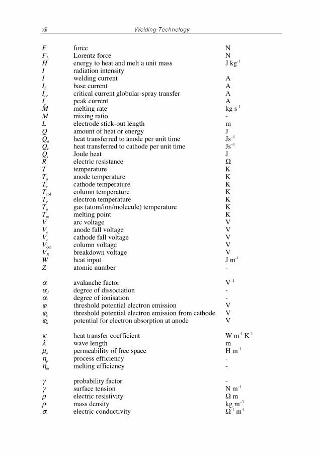
F force NFL Lorentz force NH energy to heat and melt a unit mass J kg-1
I radiation intensityI welding current AIb base current AIcr critical current globular-spray transfer AIp peak current AM melting rate kg s-1
M mixing ratio -L electrode stick-out length mQ amount of heat or energy JQa heat transferred to anode per unit time Js–1
Qc heat transferred to cathode per unit time Js–1
Qj Joule heat JR electric resistance �
T temperature KTa anode temperature KTc cathode temperature KTcol column temperature KTe electron temperature KTg gas (atom/ion/molecule) temperature KTm melting point KV arc voltage VVa anode fall voltage VVc cathode fall voltage VVcol column voltage VVB breakdown voltage VW heat input J m-1
Z atomic number -
� avalanche factor V–1
�d degree of dissociation -�i degree of ionisation -� threshold potential electron emission V�c threshold potential electron emission from cathode V�a potential for electron absorption at anode V
� heat transfer coefficient W m-1 K-1
� wave length mμo permeability of free space H m-1
�p process efficiency -�m melting efficiency -
� probability factor -� surface tension N m-1
� electric resistivity � m� mass density kg m–3
electric conductivity �-1 m-1

1
I PROCESSES

3
1 Arc Welding
1.1 Introduction
Under normal conditions gases are poor conductors of electricity, due to the fact thatthey contain no free charge carriers (electrons/ions) needed for the current flow.However, when sufficient energy is supplied to the gas, the atoms or molecules willionize, generating free electrons and ions and making conduction possible.The phenomenon of electric conduction by gases has been known for a long time. Itis manifest in a number of different forms, referred to by the somewhat misleadingname gas discharge. Examples of gas discharges are spark, lightning, Townsenddischarge, glow discharge and arc discharge. Spark and lightning are momentary,non-stationary types of discharge; their maximum lifespan is around 10-2 s. TheTownsend discharge, glow discharge and arc discharge are stationary types ofdischarge, which can exist for indefinite time. The different types of gas dischargecan be distinguished by their voltage-current characteristic, as shown in Figure 1.1.
Figure 1.1. Voltage-current characteristic of different types of gas discharge.

4 Welding Technology
The Townsend discharge is characterized by a high voltage (kilovolts) and a verylow current (micro-amperes). A high resistance in the circuit is required to maintainthis type of discharge.The glow discharge is characterized by a lower voltage (hundreds of volts) and ahigher current (milli-amperes). With this discharge a positive space charge is formedjust in front of the cathode, which leads to a strong increase of the electric field.In the case of the arc discharge, space charges also play an essential role. The voltageis lower than in the case of a glow discharge (tens of volts), while the current is muchhigher (amperes).The arc discharge is characterized by a wide power range, which makes it suitablefor a variety of industrial applications, such as welding, cutting and furnace heating.
This chapter deals with arc welding. First, the most important properties of the arcdischarge will be discussed. In the second part of the chapter, the application of thearc discharge in the arc welding process will be considered.
1.2 General characteristics of the arc
As noted above, the arc discharge (from now on simply referred to as ‘arc’), ischaracterized by a relatively low voltage and a relatively high current. A typicalcurrent-voltage characteristic is presented in Figure 1.2. The figure shows that thevoltage initially drops rapidly with current and starts to rise slightly when the currentis further increased. The energy developed in the arc per unit time equals V � I,where V is the arc voltage and I the current. Under stationary conditions, this energyequals the energy disappearing per unit time from the arc by conduction, convectionand radiation of heat.
Figure 1.2. Voltage-current characteristic of the arc.
The arc derives its name from the shape of the hot gas when the electrodes are placedhorizontally with respect to each other (Figure 1.3): because of its lower density, thehot gas will tend to rise, forming an arc shape as a result. This effect can be observed
1. Arc welding 5
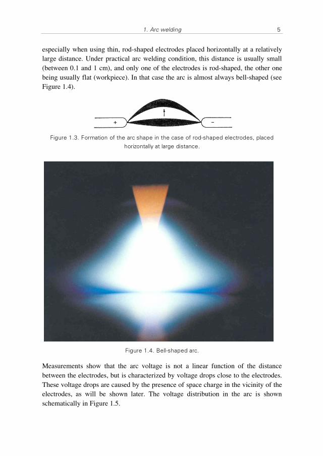
especially when using thin, rod-shaped electrodes placed horizontally at a relativelylarge distance. Under practical arc welding condition, this distance is usually small(between 0.1 and 1 cm), and only one of the electrodes is rod-shaped, the other onebeing usually flat (workpiece). In that case the arc is almost always bell-shaped (seeFigure 1.4).
Figure 1.3. Formation of the arc shape in the case of rod-shaped electrodes, placed
horizontally at large distance.
Figure 1.4. Bell-shaped arc.
Measurements show that the arc voltage is not a linear function of the distancebetween the electrodes, but is characterized by voltage drops close to the electrodes.These voltage drops are caused by the presence of space charge in the vicinity of theelectrodes, as will be shown later. The voltage distribution in the arc is shownschematically in Figure 1.5.