OTHER PROCESSES Projection Welding Seam Welding Butt Welding Flash Welding High Frequency
Upload
shahid-hussainCategory
view
55download
2description
12/22/13 Lesson 2 - Common Electric Arc Welding Processes
www.esabna.com/EUWeb/AWTC/Lesson2_1.htm 1/1
BASICWELDING FILLER METAL
TECHNOLOGY
A Correspondence Course
LESSON IICOMMON ELECTRIC ARC
WELDING PROCESSES
ESAB ESAB Welding &
Cutting Products
©COPYRIGHT 2000 THE ESAB GROUP, INC.
Lesson 1The Basics of Arc
Welding
Current
Chapter Table of
Contents
Lesson 2Common Electric
Arc Welding
Processes
Lesson 3
Covered Electrodes
for WeldingMild Steels
Lesson 4
Covered Electrodes
for Welding Low AlloySteels
Go To Test
Lesson 5
Welding Filler Metalsfor Stainless Steels
Lesson 6
Carbon & Low AlloySteel Filler Metals -GMAW,GTAW,SAW
Glossary
Lesson 7
Flux Cored ArcElectrodes CarbonLow Alloy Steels
SearchChapter
(FasterDownload)
Lesson 8Hardsurfacing
Electrodes
Turn Pages
Lesson 9
Estimating &Comparing Weld
Metal Costs
SearchDocument
(SlowerDownload)
Lesson 10
Reliability of Welding
Filler Metals

12/22/13 Lesson 2 - Common Electric Arc Welding Processes
www.esabna.com/EUWeb/AWTC/Lesson2_2.htm 1/1
© COPYRIGHT 2000 THE ESAB GROUP, INC.
TABLE OF CONTENTSLESSON II
COMMON ELECTRIC ARC WELDINGPROCESSES
2.1 INTRODUCTION .............................................................................. 1
2.2 SHIELDED METAL ARC WELDING ............................................... 1
2.2.1 Equipment & Operation ..................................................................... 2
2.2.2 Welding Pow er Sources .................................................................... 2
2.2.3 Electrode Holder................................................................................ 4
2.2.4 Ground Clamp ................................................................................... 4
2.2.5 Welding Cables ................................................................................. 4
2.2.6 Coated Electrodes ............................................................................ 4
2.3 GAS-TUNGSTEN ARC WELDING .................................................. 5
2.3.1 Equipment & Operation ..................................................................... 6
2.3.2 Pow er Sources .................................................................................. 7
2.3.3 Torches.............................................................................................. 10
2.3.4 Shielding Gases ................................................................................ 11
2.3.5 Electrodes ......................................................................................... 12
2.3.6 Summary ........................................................................................... 13
2.4 GAS METAL ARC WELDING .......................................................... 13
2.4.1 Current Density .................................................................................. 14
2.4.2 Metal Transfer Modes ........................................................................ 15
2.4.3 Equipment and Operation .................................................................. 17
2.4.4 Pow er Source.................................................................................... 18
2.4.5 Wire Feeder ...................................................................................... 19
2.4.6 Welding Gun ...................................................................................... 20
2.4.7 Shielding Gases ................................................................................ 21
2.4.7.1 Short Circuiting Transfer .................................................... 22
2.4.7.2 Spray Arc Transfer ............................................................ 23
Section Nr. Section Title Page
Lesson 1The Basics of Arc
Welding
Current
Chapter Table of
Contents
Lesson 2Common Electric
Arc Welding
Processes
Lesson 3
Covered Electrodes
for WeldingMild Steels
Lesson 4
Covered Electrodes
for Welding Low AlloySteels
Go To Test
Lesson 5
Welding Filler Metalsfor Stainless Steels
Lesson 6
Carbon & Low AlloySteel Filler Metals -GMAW,GTAW,SAW
Glossary
Lesson 7
Flux Cored ArcElectrodes CarbonLow Alloy Steels
SearchChapter
(FasterDownload)
Lesson 8Hardsurfacing
Electrodes
Turn Pages
Lesson 9
Estimating &Comparing Weld
Metal Costs
SearchDocument
(SlowerDownload)
Lesson 10
Reliability of Welding
Filler Metals

12/22/13 Lesson 2 - Common Electric Arc Welding Processes
www.esabna.com/EUWeb/AWTC/Lesson2_3.htm 1/1
© COPYRIGHT 2000 THE ESAB GROUP, INC.
2.4.7.3 Pulse Spray Transfer ......................................................... 23
2.4.8 Electrodes ......................................................................................... 23
2.5 FLUX CORED ARC WELDING ....................................................... 24
2.5.1 Self-Shielded Process ....................................................................... 24
2.5.2 Gas Shielded Process....................................................................... 25
2.5.3 Current Density .................................................................................. 26
2.5.4 Equipment ......................................................................................... 26
2.5.5 Pow er Source.................................................................................... 26
2.5.6 Wire Feeder ...................................................................................... 26
2.5.7 Welding Guns .................................................................................... 26
2.5.8 Shielding Gases ................................................................................ 27
2.6 SUBMERGED ARC WELDING ....................................................... 27
2.6.1 Submerged Arc Flux .......................................................................... 28
2.6.2 The Welding Gun ............................................................................... 28
2.6.3 Pow er Sources .................................................................................. 28
2.6.4 Equipment ......................................................................................... 28
2.6.5 Electrodes ......................................................................................... 29
2.6.6 Summary ........................................................................................... 29
2.7 ELECTROSLAG AND ELECTROGAS WELDING .......................... 30
2.7.1 Electroslag Welding........................................................................... 30
2.7.2 Flux ................................................................................................... 30
2.7.3 Process ............................................................................................. 30
2.7.4 Equipment......................................................................................... 31
2.7.5 Summary .......................................................................................... 31
Appendix A - GLOSSARY OF TERMS ................................................................. 32
TABLE OF CONTENTSLESSON II - Con't.
Section Nr. Section Title Page
Lesson 1The Basics of Arc
Welding
Current
Chapter Table of
Contents
Lesson 2Common Electric
Arc Welding
Processes
Lesson 3
Covered Electrodes
for WeldingMild Steels
Lesson 4
Covered Electrodes
for Welding Low AlloySteels
Go To Test
Lesson 5
Welding Filler Metalsfor Stainless Steels
Lesson 6
Carbon & Low AlloySteel Filler Metals -GMAW,GTAW,SAW
Glossary
Lesson 7
Flux Cored ArcElectrodes CarbonLow Alloy Steels
SearchChapter
(FasterDownload)
Lesson 8Hardsurfacing
Electrodes
Turn Pages
Lesson 9
Estimating &Comparing Weld
Metal Costs
SearchDocument
(SlowerDownload)
Lesson 10
Reliability of Welding
Filler Metals

12/22/13 Lesson 2 - Common Electric Arc Welding Processes
www.esabna.com/EUWeb/AWTC/Lesson2_4.htm 1/1
© COPYRIGHT 1998 THE ESAB GROUP, INC.
LESSON II
COMMON ELECTRIC ARC WELDING PROCESSES
2.1 INTRODUCTION
After much experimentation by others in the early 1800's, an Englishman named Wilde
obtained the f irst electric w elding patent in 1865. He successfully joined tw o small pieces of
iron by passing an electric current through both pieces producing a fusion w eld. Approximately
tw enty years later, Bernado, a Russian, w as granted a patent for an electric arc w elding
process in w hich he maintained an arc betw een a carbon electrode and the pieces to be
joined, fusing the metals together as the arc w as manually passed over the joint to be w elded.
2.1.0.1 During the 1890's, arc w elding w as accomplished w ith bare metal electrodes that
w ere consumed in the molten puddle and became part of the w eld metal. The w elds w ere of
poor quality due to the nitrogen and oxygen in the atmosphere forming harmful oxides and
nitrides in the w eld metal. Early in the Tw entieth Century, the importance of shielding the arc
from the atmosphere w as realized. Covering the electrode w ith a material that decomposed in
the heat of the arc to form a gaseous shield appeared to be the best method to accomplish
this end. As a result, various methods of covering electrodes, such as w rapping and dipping,
w ere tried. These efforts culminated in the extruded coated electrode in the mid-1920's,
greatly improving the quality of the w eld metal and providing w hat many consider the most
signif icant advance in electric arc w elding.
2.1.0.2 Since w elding w ith coated electrodes is a rather slow procedure, more rapid
w elding processes w ere developed. This lesson w ill cover the more commonly used electric
arc w elding processes in use today.
2.2 SHIELDED METAL ARC WELDING
Shielded Metal Arc Welding*, also know n as manual metal arc w elding, stick w elding, or
electric arc w elding, is the most w idely used of the various arc w elding processes. Welding is
performed w ith the heat of an electric arc that is maintained betw een the end of a coated metal
electrode and the w ork piece (See Figure 1). The heat produced by the arc melts the base
metal, the electrode core rod, and the coating. As the molten metal droplets are transferred
across the arc and into the molten w eld puddle, they are shielded from the atmosphere by the
gases produced from the decomposition of the f lux coating. The molten slag f loats to the top
of the w eld puddle w here it protects the w eld metal from the atmosphere during solidif ication.
Lesson 1The Basics of Arc
Welding
Current
Chapter Table of
Contents
Lesson 2Common Electric
Arc Welding
Processes
Lesson 3
Covered Electrodes
for WeldingMild Steels
Lesson 4
Covered Electrodes
for Welding Low AlloySteels
Go To Test
Lesson 5
Welding Filler Metalsfor Stainless Steels
Lesson 6
Carbon & Low AlloySteel Filler Metals -GMAW,GTAW,SAW
Glossary
Lesson 7
Flux Cored ArcElectrodes CarbonLow Alloy Steels
SearchChapter
(FasterDownload)
Lesson 8Hardsurfacing
Electrodes
Turn Pages
Lesson 9
Estimating &Comparing Weld
Metal Costs
SearchDocument
(SlowerDownload)
Lesson 10
Reliability of Welding
Filler Metals
12/22/13 Lesson 2 - Common Electric Arc Welding Processes
www.esabna.com/EUWeb/AWTC/Lesson2_5.htm 1/1
© COPYRIGHT 1998 THE ESAB GROUP, INC.
LESSON II
Other functions of the coating are to provide
arc stability and control bead shape. More
information on coating functions w ill be
covered in subsequent lessons.
* Shielded Metal Arc Welding (SMAW) is the
terminology approved by the American
Welding Society.
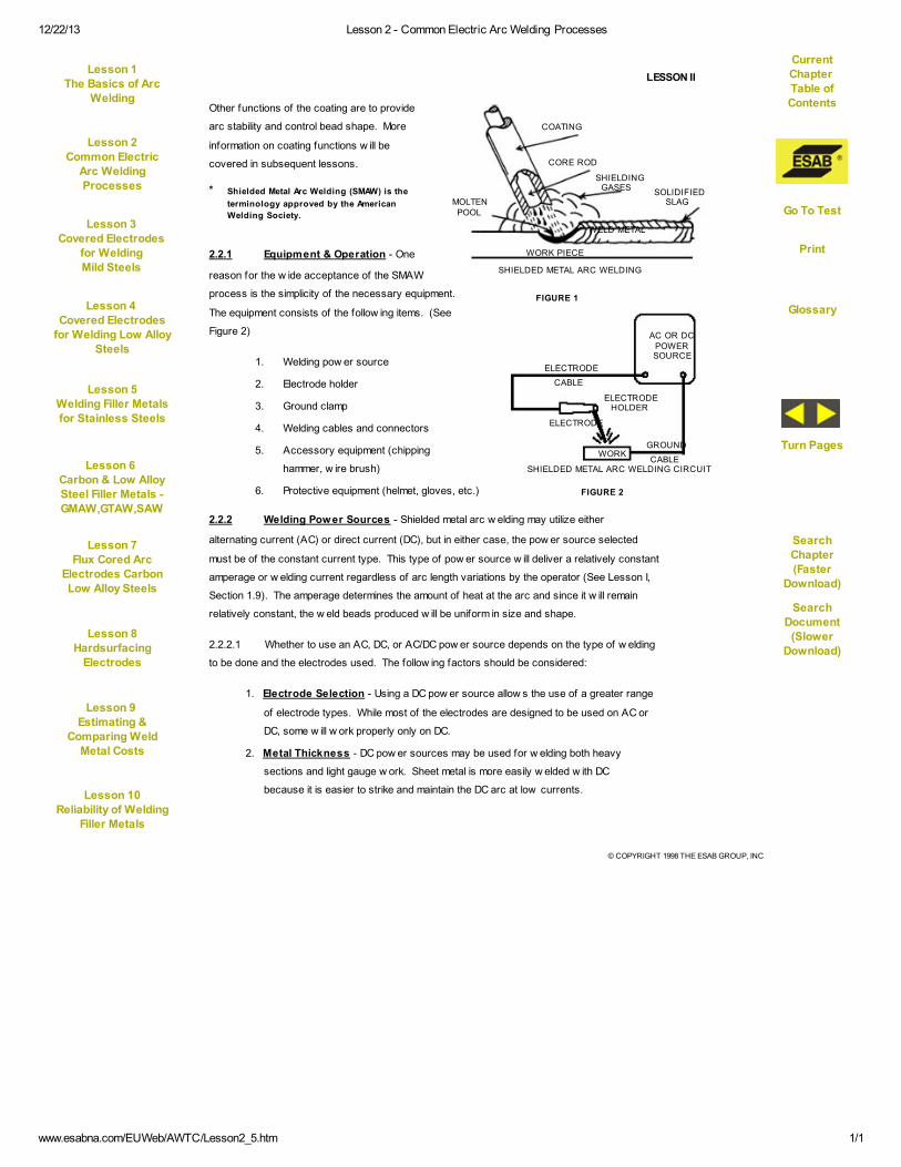
2.2.1 Equipment & Operation - One
reason for the w ide acceptance of the SMAW
process is the simplicity of the necessary equipment.
The equipment consists of the follow ing items. (See
Figure 2)
1. Welding pow er source
2. Electrode holder
3. Ground clamp
4. Welding cables and connectors
5. Accessory equipment (chipping
hammer, w ire brush)
6. Protective equipment (helmet, gloves, etc.)
2.2.2 Welding Power Sources - Shielded metal arc w elding may utilize either
alternating current (AC) or direct current (DC), but in either case, the pow er source selected
must be of the constant current type. This type of pow er source w ill deliver a relatively constant
amperage or w elding current regardless of arc length variations by the operator (See Lesson I,
Section 1.9). The amperage determines the amount of heat at the arc and since it w ill remain
relatively constant, the w eld beads produced w ill be uniform in size and shape.
2.2.2.1 Whether to use an AC, DC, or AC/DC pow er source depends on the type of w elding
to be done and the electrodes used. The follow ing factors should be considered:
1. Electrode Selection - Using a DC pow er source allow s the use of a greater range
of electrode types. While most of the electrodes are designed to be used on AC or
DC, some w ill w ork properly only on DC.
2. Metal Thickness - DC pow er sources may be used for w elding both heavy
sections and light gauge w ork. Sheet metal is more easily w elded w ith DC
because it is easier to strike and maintain the DC arc at low currents.
FIGURE 1
CORE ROD
SHIELDINGGASES
SOLIDIFIEDSLAG
WELD METAL
WORK PIECE
MOLTENPOOL
SHIELDED METAL ARC WELDING
AC OR DCPOWERSOURCE
ELECTRODE
CABLE
ELECTRODEHOLDER
ELECTRODE
GROUND
CABLEWORK
SHIELDED METAL ARC WELDING CIRCUIT
FIGURE 2
Lesson 1The Basics of Arc
Welding
Current
Chapter Table of
Contents
Lesson 2Common Electric
Arc Welding
Processes
Lesson 3
Covered Electrodes
for WeldingMild Steels
Lesson 4
Covered Electrodes
for Welding Low AlloySteels
Go To Test
Lesson 5
Welding Filler Metalsfor Stainless Steels
Lesson 6
Carbon & Low AlloySteel Filler Metals -GMAW,GTAW,SAW
Glossary
Lesson 7
Flux Cored ArcElectrodes CarbonLow Alloy Steels
SearchChapter
(FasterDownload)
Lesson 8Hardsurfacing
Electrodes
Turn Pages
Lesson 9
Estimating &Comparing Weld
Metal Costs
SearchDocument
(SlowerDownload)
Lesson 10
Reliability of Welding
Filler Metals
COATING

12/22/13 Lesson 2 - Common Electric Arc Welding Processes
www.esabna.com/EUWeb/AWTC/Lesson2_6.htm 1/1
© COPYRIGHT 1998 THE ESAB GROUP, INC.
LESSON II
3. Distance from Work - If the distance from the w ork to the pow er source is great,
AC is the best choice since the voltage drop through the cables is low er than w ith
DC. Even though w elding cables are made of copper or aluminum (both good
conductors), the resistance in the cables becomes greater as the cable length
increases. In other w ords, a voltage reading taken betw een the electrode and the
w ork w ill be somew hat low er than a reading taken at the output terminals of the
pow er source. This is know n as voltage drop.
4. Welding Position (See Appendix A - Glossary of Terms) - Because DC may be
operated at low er w elding currents, it is more suitable for overhead and vertical
w elding than AC. AC can successfully be used for out-of-position w ork if proper
electrodes are selected.
5. Arc Blow - When w elding w ith DC, magnetic f ields are set up throughout the
w eldment. In w eldments that have varying thickness and protrusions, this magnetic
f ield can affect the arc by making it stray or f luctuate in direction. This condition is
especially troublesome w hen w elding in corners. AC seldom causes this problem
because of the rapidly reversing magnetic f ield produced.
2.2.2.2 Combination pow er sources that produce both AC and DC are available and
provide the versatility necessary to select the proper w elding current for the application.
2.2.2.3 When using a DC pow er source, the question of w hether to use electrode negative
or positive polarity arises. Some electrodes operate on both DC straight and reverse polarity,
and others on DC negative or DC positive polarity only. Direct current f low s in one direction in
an electrical circuit and the direction of current f low and the composition of the electrode
coating w ill have a definite effect on the w elding arc and w eld bead. Figure 3 show s the
connections and effects of straight and reverse polarity.
2.2.2.4 Electrode negative (-) produces w elds w ith shallow penetration; how ever, the
electrode melt-off rate is high. The w eld bead is rather w ide and shallow as show n at "A" in
Figure 3. Electrode
positive (+)
produces w elds w ith
deep penetration
and a narrow er w eld
bead as show n at
"B" in Figure 3.
FIGURE 3
DCPOWER SOURCE
ELECTRODE
DCPOWER SOURCE
ELECTRODE
A
HIGHER BURN-OFF RATE,LESS PENETRATION
DEEP PENETRATION,LOW BURN-OFF RATE
WORK PIECE
B
STRAIGHT POLARITY REVERSE POLARITY
WORK PIECE
Current
Chapter Table of
Contents
Lesson 1The Basics of Arc
Welding
Lesson 2Common Electric
Arc Welding
Processes
Lesson 3
Covered Electrodes
for WeldingMild Steels
Go To Test
Lesson 4
Covered Electrodes
for Welding Low AlloySteels
Lesson 5
Welding Filler Metalsfor Stainless Steels
Glossary
Lesson 6
Carbon & Low AlloySteel Filler Metals -GMAW,GTAW,SAW
SearchChapter
(FasterDownload)
Lesson 7
Flux Cored ArcElectrodes CarbonLow Alloy Steels
Turn Pages
Lesson 8Hardsurfacing
Electrodes
SearchDocument
(SlowerDownload)
Lesson 9
Estimating &Comparing Weld
Metal Costs
Lesson 10
Reliability of Welding
Filler Metals

12/22/13 Lesson 2 - Common Electric Arc Welding Processes
www.esabna.com/EUWeb/AWTC/Lesson2_7.htm 1/1
© COPYRIGHT 1998 THE ESAB GROUP, INC.
LESSON II
2.2.2.5 While polarity affects the penetration and burn-off rate, the electrode coating also
has a strong influence on arc characteristics. Performance of individual electrodes w ill be
discussed in succeeding lessons.
2.2.3 Electrode Holder - The electrode holder connects to the w elding cable and con-
ducts the w elding current to the electrode. The insulated handle is used to guide the electrode
over the w eld joint and feed the electrode over the w eld joint and feed the electrode into the
w eld puddle as it is consumed. Electrode holders are available in different sizes and are rated
on their current carrying capacity.
2.2.4 Ground Clamp - The ground clamp is used to connect the ground cable to the w ork
piece. It may be connected directly to the w ork or to the table or f ixture upon w hich the w ork is
positioned. Being a part of the w elding circuit, the ground clamp must be capable of carrying
the w elding current w ithout overheating due to electrical resistance.
2.2.5 Welding Cables - The electrode cable and the ground cable are important parts of
the w elding circuit. They must be very f lexible and have a tough heat-resistant insulation.
Connections at the electrode holder, the ground clamp, and at the pow er source lugs must be
soldered or w ell crimped to assure low electrical resistance. The cross-sectional area of the
cable must be suff icient size to carry the w elding current w ith a minimum of voltage drop.
Increasing the cable length necessitates increasing the cable diameter to lessen resistance
and voltage drop. The table in Figure 4 lists the suggested American Wire Gauge (AWG)
cable size to be used for various w elding currents and cable lengths.
Total Cable Length (Ground Lead Plus Electrode Lead)
Up to 50 f t. Up to 100 f t. Up to 250 f t. Up to 500 f t.
Cable Voltage Cable Voltage Cable Voltage Cable Voltage
Size Drop Size Drop Size Drop Size Drop
20 to 180 #3 1.8 #2 2.9 #1 5.7 #0 9.1 180 Amps30 to 250 #2 1.8 #1 2.5 #0 5.0 #0 9.9 200 Amps
60 to 375 #0 1.7 #0 3.0 #00 5.9 #000 9.3 300 Amps80 to 500 #00 1.8 #000 2.5 #0000 5.0 #0000 9.9 400 Amps
100 to 600 #00 2.0 #0000 2.5 ... ... ... 500 Amps
Voltage drops indicated do not include any drop caused by poor connection, electrode holder, or work metal
WeldingServ ice
Range(Amperes)
Voltage
DropFigured
At
FIGURE 4
2.2.6 Coated Electrodes - Various types of coated electrodes are used in shielded
metal arc w elding. Electrodes used for w elding mild or carbon steels are quite different than
those used for w elding the low alloys and stainless steels. Details on the specif ic types w ill be
covered in subsequent lessons.
Current
Chapter Table of
Contents
Lesson 1The Basics of Arc
Welding
Lesson 2Common Electric
Arc Welding
Processes
Lesson 3
Covered Electrodes
for WeldingMild Steels
Go To Test
Lesson 4
Covered Electrodes
for Welding Low AlloySteels
Lesson 5
Welding Filler Metalsfor Stainless Steels
Glossary
Lesson 6
Carbon & Low AlloySteel Filler Metals -GMAW,GTAW,SAW
SearchChapter
(FasterDownload)
Lesson 7
Flux Cored ArcElectrodes CarbonLow Alloy Steels
Turn Pages
Lesson 8Hardsurfacing
Electrodes
SearchDocument
(SlowerDownload)
Lesson 9
Estimating &Comparing Weld
Metal Costs
Lesson 10
Reliability of Welding
Filler Metals
12/22/13 Lesson 2 - Common Electric Arc Welding Processes
www.esabna.com/EUWeb/AWTC/Lesson2_8.htm 1/1
© COPYRIGHT 1998 THE ESAB GROUP, INC.
LESSON II
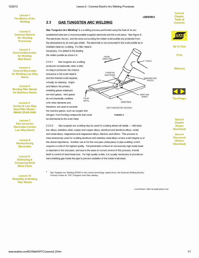
2.3 GAS TUNGSTEN ARC WELDING
Gas Tungsten Arc Welding* is a w elding process performed using the heat of an arc
established betw een a nonconsumable tungsten electrode and the w ork piece. See Figure 5.
The electrode, the arc, and the area surrounding the molten w eld puddle are protected from
the atmosphere by an inert gas shield. The electrode is not consumed in the w eld puddle as in
shielded metal arc w elding. If a f iller metal is
necessary, it is added to the leading
the molten puddle as show n in
2.3.0.1 Gas tungsten arc w elding
produces exceptionally clean w elds
no slag is produced, the chance
inclusions in the w eld metal is
and the f inished w eld requires
virtually no cleaning. Argon
and Helium, the primary
shielding gases employed,
are inert gases. Inert gases
do not chemically combine
w ith other elements and
therefore, are used to exclude
the reactive gases, such as oxygen and
nitrogen, from forming compounds that could
be detrimental to the w eld metal.
2.3.0.2 Gas tungsten arc w elding may be used for w elding almost all metals — mild steel,
low alloys, stainless steel, copper and copper alloys, aluminum and aluminum alloys, nickel
and nickel alloys, magnesium and magnesium alloys, titanium, and others. This process is
most extensively used for w elding aluminum and stainless steel alloys w here w eld integrity is of
the utmost importance. Another use is for the root pass (initial pass) in pipe w elding, w hich
requires a w eld of the highest quality. Full penetration w ithout an excessively high inside bead
is important in the root pass, and due to the ease of current control of this process, it lends
itself to control of back-bead size. For high quality w elds, it is usually necessary to provide an
inert shielding gas inside the pipe to prevent oxidation of the inside w eld bead.
* Gas Tungsten Arc Welding (GTAW) is the current terminology approv ed by the American Welding Society ,
f ormerly known as "TIG" (Tungsten Inert Gas) welding.
FIGURE 5
TRAVELDIRECTION
TORCH
SHIELDING GASNOZZLE
INERT GAS
SHIELD
WORK PIECE
TUNGSTEN
ELECTRODE
ARC
FILLER
METAL
GAS TUNGSTEN ARC WELDING
Current
Chapter Table of
Contents
Lesson 1The Basics of Arc
Welding
Lesson 2Common Electric
Arc Welding
Processes
Lesson 3
Covered Electrodes
for WeldingMild Steels
Go To Test
Lesson 4
Covered Electrodes
for Welding Low AlloySteels
Lesson 5
Welding Filler Metalsfor Stainless Steels
Glossary
Lesson 6
Carbon & Low AlloySteel Filler Metals -GMAW,GTAW,SAW
SearchChapter
(FasterDownload)
Lesson 7
Flux Cored ArcElectrodes CarbonLow Alloy Steels
Turn Pages
Lesson 8Hardsurfacing
Electrodes
SearchDocument
(SlowerDownload)
Lesson 9
Estimating &Comparing Weld
Metal Costs
Lesson 10
Reliability of Welding
Filler Metals
12/22/13 Lesson 2 - Common Electric Arc Welding Processes
www.esabna.com/EUWeb/AWTC/Lesson2_9.htm 1/1
© COPYRIGHT 1998 THE ESAB GROUP, INC.
LESSON II
2.3.0.3 Gas tungsten arc w elding lends itself to both manual and automatic operation. In
manual operation, the w elder holds the torch in one hand and directs the arc into the w eld joint.
The f iller metal is fed manually into the leading edge of the puddle. In automatic applications,
the torch may be automatically moved over a stationary w ork piece or the torch may be
stationary w ith the w ork moved or rotated in relation to the torch. Filler metal, if required, is
also fed automatically.
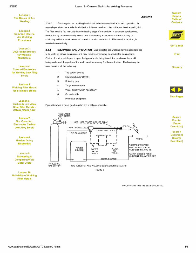
2.3.1 EQUIPMENT AND OPERATION - Gas tungsten arc w elding may be accomplished
w ith relatively simple equipment, or it may require some highly sophisticated components.
Choice of equipment depends upon the type of metal being joined, the position of the w eld
being made, and the quality of the w eld metal necessary for the application. The basic equip-
ment consists of the follow ing:
1. The pow er source
2. Electrode holder (torch)
3. Shielding gas
4. Tungsten electrode
5. Water supply w hen necessary
6. Ground cable
7. Protective equipment
Figure 6 show s a basic gas tungsten arc w elding schematic.
FIGURE 6
REGULATORFLOW METER
GAS HOSE (WATER COOLED ONLY)
TORCH
* COMPOSITE CABLE
WATER COOLER
GAS COOLED ONLY
WELDING CABLE
SHIELDINGGAS SUPPLY
POWERSOURCE WATER
FROMTORCH
WATERTO
TORCH
GROUND CABLE
WORK
* COMPOSITE CABLE
GAS COOLED TORCH.CURRENT IN & GAS IN.
WATER COOLED TORCH.CURRENT IN & WATER OUT
GAS TUNGSTEN ARC WELDING CONNECTION SCHEMATIC
Current
Chapter Table of
Contents
Lesson 1The Basics of Arc
Welding
Lesson 2Common Electric
Arc Welding
Processes
Lesson 3
Covered Electrodes
for WeldingMild Steels
Go To Test
Lesson 4
Covered Electrodes
for Welding Low AlloySteels
Lesson 5
Welding Filler Metalsfor Stainless Steels
Glossary
Lesson 6
Carbon & Low AlloySteel Filler Metals -GMAW,GTAW,SAW
SearchChapter
(FasterDownload)
Lesson 7
Flux Cored ArcElectrodes CarbonLow Alloy Steels
Turn Pages
Lesson 8Hardsurfacing
Electrodes
SearchDocument
(SlowerDownload)
Lesson 9
Estimating &Comparing Weld
Metal Costs
Lesson 10
Reliability of Welding
Filler Metals
12/22/13 Lesson 2 - Common Electric Arc Welding Processes
www.esabna.com/EUWeb/AWTC/Lesson2_10.htm 1/1
© COPYRIGHT 1998 THE ESAB GROUP, INC.
LESSON II
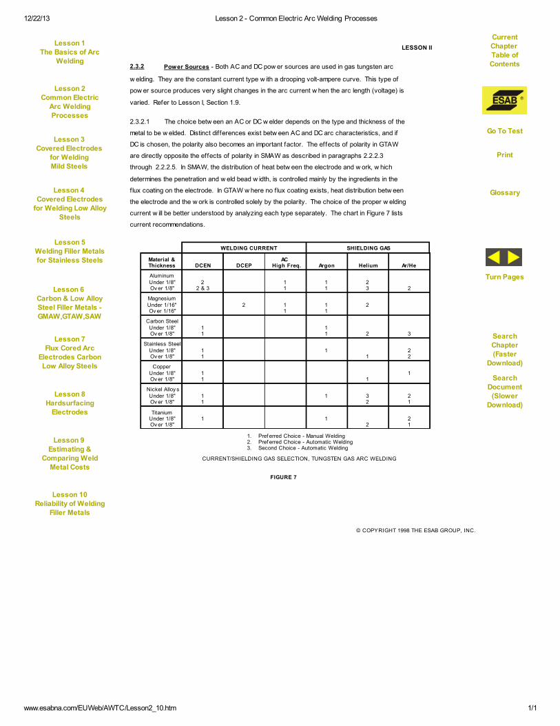
2.3.2 Power Sources - Both AC and DC pow er sources are used in gas tungsten arc
w elding. They are the constant current type w ith a drooping volt-ampere curve. This type of
pow er source produces very slight changes in the arc current w hen the arc length (voltage) is
varied. Refer to Lesson I, Section 1.9.
2.3.2.1 The choice betw een an AC or DC w elder depends on the type and thickness of the
metal to be w elded. Distinct differences exist betw een AC and DC arc characteristics, and if
DC is chosen, the polarity also becomes an important factor. The effects of polarity in GTAW
are directly opposite the effects of polarity in SMAW as described in paragraphs 2.2.2.3
through 2.2.2.5. In SMAW, the distribution of heat betw een the electrode and w ork, w hich
determines the penetration and w eld bead w idth, is controlled mainly by the ingredients in the
flux coating on the electrode. In GTAW w here no f lux coating exists, heat distribution betw een
the electrode and the w ork is controlled solely by the polarity. The choice of the proper w elding
current w ill be better understood by analyzing each type separately. The chart in Figure 7 lists
current recommendations.
FIGURE 7
Material &Thickness DCEN DCEP
ACHigh Freq. Argon Helium Ar/He
AluminumUnder 1/8"Ov er 1/8"
22 & 3
11
11
23 2
MagnesiumUnder 1/16"Ov er 1/16"
2 11
11
2
Carbon SteelUnder 1/8"Ov er 1/8"
11
11 2 3
Stainless SteelUnder 1/8"Ov er 1/8"
11
11
22
CopperUnder 1/8"Ov er 1/8"
11 1
1
Nickel Alloy sUnder 1/8"Ov er 1/8"
11
1 32
21
TitaniumUnder 1/8"Ov er 1/8"
1 12
21
WELDING CURRENT SHIELDING GAS
1. Pref erred Choice - Manual Welding2. Pref erred Choice - Automatic Welding3. Second Choice - Automatic Welding
CURRENT/SHIELDING GAS SELECTION, TUNGSTEN GAS ARC WELDING
Lesson 1The Basics of Arc
Welding
Current
Chapter Table of
Contents
Lesson 2Common Electric
Arc Welding
Processes
Lesson 3
Covered Electrodes
for WeldingMild Steels
Lesson 4
Covered Electrodes
for Welding Low AlloySteels
Go To Test
Lesson 5
Welding Filler Metalsfor Stainless Steels
Lesson 6
Carbon & Low AlloySteel Filler Metals -GMAW,GTAW,SAW
Glossary
Lesson 7
Flux Cored ArcElectrodes CarbonLow Alloy Steels
SearchChapter
(FasterDownload)
Lesson 8Hardsurfacing
Electrodes
Turn Pages
Lesson 9
Estimating &Comparing Weld
Metal Costs
SearchDocument
(SlowerDownload)
Lesson 10
Reliability of Welding
Filler Metals

12/22/13 Lesson 2 - Common Electric Arc Welding Processes
www.esabna.com/EUWeb/AWTC/Lesson2_11.htm 1/1
© COPYRIGHT 1998 THE ESAB GROUP, INC.
LESSON II
2.3.2.2 Direct current electrode negative (DCEN) is produced w hen the electrode is
connected to the negative terminal of the pow er source. Since the electrons f low from the
electrode to the plate, approximately 70% of the heat of the arc is concentrated at the w ork,
and approximately 30% at the electrode end. This allow s the use of smaller tungsten elec-
trodes that produce a relatively narrow concentrated arc. The w eld shape has deep penetra-
tion and is quite narrow . See Figure 8. Direct current electrode negative is suitable for w eld-
ing most metals. Magnesium and aluminum have a refractory oxide coating on the surface that
must be physically removed immediately prior to w elding if DCSP is to be used.
2.3.2.3 Direct current electrode positive (DCEP) is produced w hen the electrode is
connected to the positive terminal of the w elding pow er source. In this condition, the electrons
flow from the w ork to the electrode tip, concentrating approximately 70% of the heat of the arc
at the electrode and 30% at the w ork. This higher heat at the electrode necessitates using
larger diameter tungsten to prevent it from melting and contaminating the w eld metal. Since
the electrode diameter is larger and the heat is less concentrated at the w ork, the resultant
w eld bead is relatively w ide and shallow . See Figure 8.
2.3.2.4 Aluminum and magnesium are tw o metals that have a heavy oxide coating that acts
as an insulator and must be removed before successful w elding can take place. Welding w ith
electrode positive provides a good oxide cleaning action in the arc. If w e w ere to study the
physics of the w elding arc, w e f ind that the electric current causes the shielding gas atoms to
lose some of their electrons. Since electrons are negatively charged, these gas atoms now
are unbalanced and have an excessive positive charge. As w e learned in Lesson I, unlike
charges attract. These positively charged atoms (or positive ions as they are know n in
FIGURE 8
Electrode Oxide HeatPolarity Penetration Cleaning Concentration
Direct Current
Alternating Current
Medium Penetration
Medium WidthBead
Good
Cleans Oxideon Each Half
Cy cleAlternates BetweenElectrode and Work
Straight PolarityElectrode Negativ e
DeepPenetration
NarrowBead
Direct Current
Rev erse PolarityElectrode Positiv e
Shallow Penetration
Wide BeadMaximum
None AtWork
AtElectrode
GAS IONS
+
_
ELECTRONFLOW
_
_
+
+
EFFECTS OF CURRENT TYPE - GAS TUNGSTEN ARC WELDING
Lesson 1The Basics of Arc
Welding
Current
Chapter Table of
Contents
Lesson 2Common Electric
Arc Welding
Processes
Lesson 3
Covered Electrodes
for WeldingMild Steels
Lesson 4
Covered Electrodes
for Welding Low AlloySteels
Go To Test
Lesson 5
Welding Filler Metalsfor Stainless Steels
Lesson 6
Carbon & Low AlloySteel Filler Metals -GMAW,GTAW,SAW
Glossary
Lesson 7
Flux Cored ArcElectrodes CarbonLow Alloy Steels
SearchChapter
(FasterDownload)
Lesson 8Hardsurfacing
Electrodes
Turn Pages
Lesson 9
Estimating &Comparing Weld
Metal Costs
SearchDocument
(SlowerDownload)
Lesson 10
Reliability of Welding
Filler Metals
12/22/13 Lesson 2 - Common Electric Arc Welding Processes
www.esabna.com/EUWeb/AWTC/Lesson2_12.htm 1/1
© COPYRIGHT 1998 THE ESAB GROUP, INC.
LESSON II
chemical terminology) are attracted to the negative pole, in this case the w ork, at high velocity.
Upon striking the w ork surface, they dislodge the oxide coating permitting good electrical
conductivity for the maintenance of the arc, and eliminate the impurities in the w eld metal that
could be caused by these oxides.
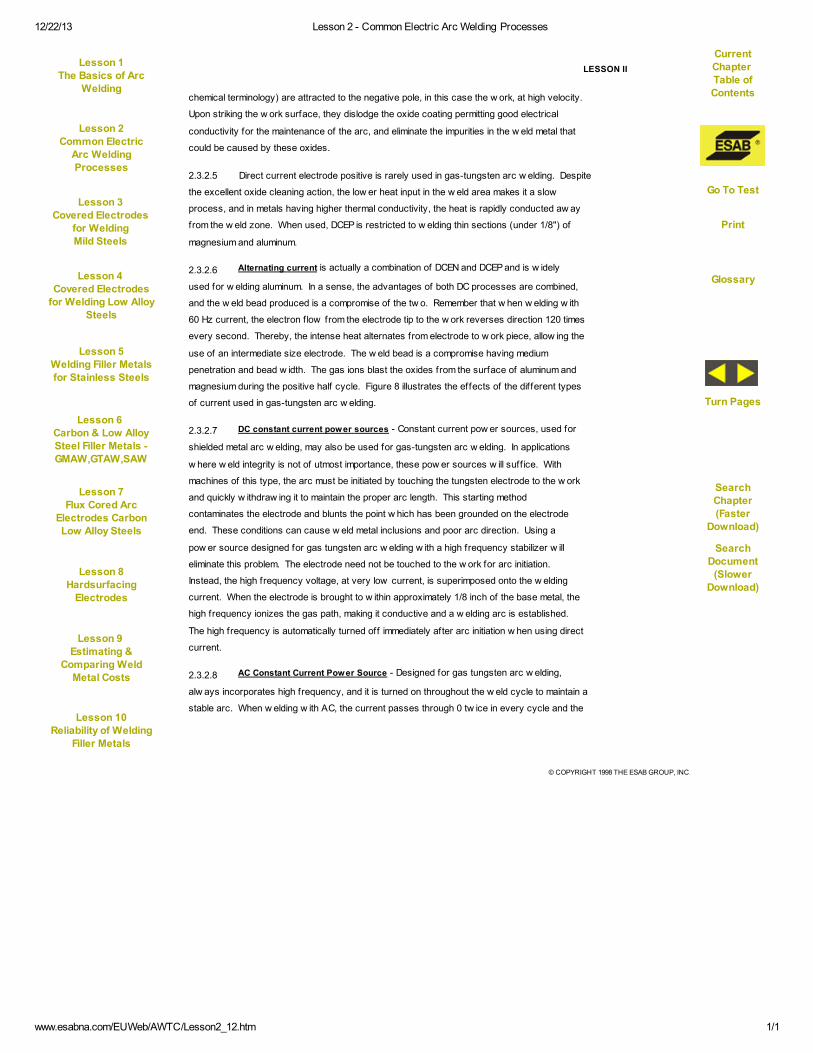
2.3.2.5 Direct current electrode positive is rarely used in gas-tungsten arc w elding. Despite
the excellent oxide cleaning action, the low er heat input in the w eld area makes it a slow
process, and in metals having higher thermal conductivity, the heat is rapidly conducted aw ay
from the w eld zone. When used, DCEP is restricted to w elding thin sections (under 1/8") of
magnesium and aluminum.
2.3.2.6 Alternating current is actually a combination of DCEN and DCEP and is w idely
used for w elding aluminum. In a sense, the advantages of both DC processes are combined,
and the w eld bead produced is a compromise of the tw o. Remember that w hen w elding w ith
60 Hz current, the electron f low from the electrode tip to the w ork reverses direction 120 times
every second. Thereby, the intense heat alternates from electrode to w ork piece, allow ing the
use of an intermediate size electrode. The w eld bead is a compromise having medium
penetration and bead w idth. The gas ions blast the oxides from the surface of aluminum and
magnesium during the positive half cycle. Figure 8 illustrates the effects of the different types
of current used in gas-tungsten arc w elding.
2.3.2.7 DC constant current power sources - Constant current pow er sources, used for
shielded metal arc w elding, may also be used for gas-tungsten arc w elding. In applications
w here w eld integrity is not of utmost importance, these pow er sources w ill suff ice. With
machines of this type, the arc must be initiated by touching the tungsten electrode to the w ork
and quickly w ithdraw ing it to maintain the proper arc length. This starting method
contaminates the electrode and blunts the point w hich has been grounded on the electrode
end. These conditions can cause w eld metal inclusions and poor arc direction. Using a
pow er source designed for gas tungsten arc w elding w ith a high frequency stabilizer w ill
eliminate this problem. The electrode need not be touched to the w ork for arc initiation.
Instead, the high frequency voltage, at very low current, is superimposed onto the w elding
current. When the electrode is brought to w ithin approximately 1/8 inch of the base metal, the
high frequency ionizes the gas path, making it conductive and a w elding arc is established.
The high frequency is automatically turned off immediately after arc initiation w hen using direct
current.
2.3.2.8 AC Constant Current Power Source - Designed for gas tungsten arc w elding,
alw ays incorporates high frequency, and it is turned on throughout the w eld cycle to maintain a
stable arc. When w elding w ith AC, the current passes through 0 tw ice in every cycle and the
Lesson 1The Basics of Arc
Welding
Current
Chapter Table of
Contents
Lesson 2Common Electric
Arc Welding
Processes
Lesson 3
Covered Electrodes
for WeldingMild Steels
Lesson 4
Covered Electrodes
for Welding Low AlloySteels
Go To Test
Lesson 5
Welding Filler Metalsfor Stainless Steels
Lesson 6
Carbon & Low AlloySteel Filler Metals -GMAW,GTAW,SAW
Glossary
Lesson 7
Flux Cored ArcElectrodes CarbonLow Alloy Steels
SearchChapter
(FasterDownload)
Lesson 8Hardsurfacing
Electrodes
Turn Pages
Lesson 9
Estimating &Comparing Weld
Metal Costs
SearchDocument
(SlowerDownload)
Lesson 10
Reliability of Welding
Filler Metals

12/22/13 Lesson 2 - Common Electric Arc Welding Processes
www.esabna.com/EUWeb/AWTC/Lesson2_13.htm 1/1
© COPYRIGHT 1998 THE ESAB GROUP, INC.
LESSON II
arc must be reestablished each time it does so. The oxide coating on metals, such as
aluminum and magnesium, can act much like a rectif ier as discussed in Lesson I. The positive
half-cycle w ill be eliminated if the arc does not reignite, causing an unstable condition.
Continuous high frequency maintains an ionized path for the w elding arc, and assures arc re-
ignition each time the current changes direction. AC is extensively used for w elding aluminum
and magnesium.
2.3.2.9 AC/DC Constant Current Power Sources - Designed for gas tungsten arc
w elding, are available, and can be used for w elding practically all metals. The gas tungsten
arc w elding process is usually chosen because of the high quality w elds it can produce. The
metals that are commonly w elded w ith this process, such as stainless steel, aluminum and
some of the more exotic metals, cost many times the price of mild steel; and therefore, the
pow er sources designed for this process have many desirable features to insure high quality
w elds. Among these are:
1. Remote current control, w hich allow s the operator to control w elding amperage
w ith a hand control on the torch, or a foot control at the w elding station.
2. Automatic soft-start, w hich prevents a high current surge w hen the arc is
initiated.
3. Shielding gas and cooling water solenoid valves, w hich automatically control
f low before, during and for an adjustable length of time after the w eld is completed.
4. Spot-weld timers, w hich automatically control all elements during each
spot-w eld cycle.
Other options and accessories are also available.
2.3.2.10 Pow er sources for automatic w elding w ith complete programmable output are also
available. Such units are used extensively for the automatic w elding of pipe in position. The
w elding current is automatically varied as the torch travels around the pipe. Some units
provide a pulsed w elding current w here the amperage is automatically varied betw een a low
and high several times per second. This produces w elds w ith good penetration and improved
w eld bead shape.
2.3.3 Torches - The torch is actually an electrode holder that supplies w elding current to
the tungsten electrode, and an inert gas shield to the arc zone. The electrode is held in a
collet-like clamping device that allow s adjustment so that the proper length of electrode pro-
trudes beyond the shielding gas cup. Manual torches are designed to accept electrodes of 3
Current
Chapter Table of
Contents
Lesson 1The Basics of Arc
Welding
Lesson 2Common Electric
Arc Welding
Processes
Lesson 3
Covered Electrodes
for WeldingMild Steels
Go To Test
Lesson 4
Covered Electrodes
for Welding Low AlloySteels
Lesson 5
Welding Filler Metalsfor Stainless Steels
Glossary
Lesson 6
Carbon & Low AlloySteel Filler Metals -GMAW,GTAW,SAW
SearchChapter
(FasterDownload)
Lesson 7
Flux Cored ArcElectrodes CarbonLow Alloy Steels
Turn Pages
Lesson 8Hardsurfacing
Electrodes
SearchDocument
(SlowerDownload)
Lesson 9
Estimating &Comparing Weld
Metal Costs
Lesson 10
Reliability of Welding
Filler Metals

12/22/13 Lesson 2 - Common Electric Arc Welding Processes
www.esabna.com/EUWeb/AWTC/Lesson2_14.htm 1/1
© COPYRIGHT 1998 THE ESAB GROUP, INC.
LESSON II
inch or 7 inch lengths. Torches may be either air or w ater-cooled. The air-cooled types actu-
ally are cooled to a degree by the shielding gas that is fed to the torch head through a compos-
ite cable. The gas actually surrounds the copper w elding cable, affording some degree of
cooling. Water-cooled torches are usually used for applications w here the w elding current
exceeds 200 amperes. The w ater inlet hose is connected to the torch head. Circulating
around the torch head, the w ater leaves the torch via the current-in hose and cable assembly.
Cooling the w elding cable in this manner allow s the use of a smaller diameter cable that is
more f lexible and lighter in w eight.
2.3.3.1 The gas nozzles are made of ceramic materials and are available in various sizes
and shapes. In some heavy duty, high current applications, metal w ater-cooled nozzles are
used.
2.3.3.2 A sw itch on the torch is used to energize the electrode w ith w elding current and start
the shielding gas f low . High frequency current and w ater f low are also initiated by this sw itch if
the pow er source is so equipped. In many installations, these functions are initiated by a foot
control that also is capable of controlling the w elding current. This method gives the operator
full control of the arc. The usual w elding method is to start the arc at a low current, gradually
increase the current until a molten pool is achieved, and w elding begins. At the end of the
w eld, current is slow ly decreases and the arc extinguished, preventing the crater that forms at
the end of the w eld w hen the arc is broken abruptly.
2.3.4 Shielding Gases - Argon and helium are the major shielding gases used in gas
tungsten arc w elding. In some applications, mixtures of the tw o gases prove advantageous.
To a lesser extent, hydrogen is mixed w ith argon or helium for special applications.
2.3.4.1 Argon and helium are colorless, odorless, tasteless and nontoxic gases. Both are
inert gases, w hich means that they do not readily combine w ith other elements. They w ill not
burn nor support combustion. Commercial grades used for w elding are 99.99% pure. Argon
is .38% heavier than air and about 10 times heavier than helium. Both gases ionize w hen
present in an electric arc. This means that the gas atoms lose some of their electrons that
have a negative charge. These unbalanced gas atoms, properly called positive ions, now
have a positive charge and are attracted to the negative pole in the arc. When the arc is
positive and the w ork is negative, these positive ions impinge upon the w ork and remove
surface oxides or scale in the w eld area.
2.3.4.2 Argon is most commonly used of the shielding gases. Excellent arc starting and
ease of use make it most desirable for manual w elding. Argon produces a better cleaning
action w hen w elding aluminum and magnesium w ith alternating current. The arc produced is
Current
Chapter Table of
Contents
Lesson 1The Basics of Arc
Welding
Lesson 2Common Electric
Arc Welding
Processes
Lesson 3
Covered Electrodes
for WeldingMild Steels
Go To Test
Lesson 4
Covered Electrodes
for Welding Low AlloySteels
Lesson 5
Welding Filler Metalsfor Stainless Steels
Glossary
Lesson 6
Carbon & Low AlloySteel Filler Metals -GMAW,GTAW,SAW
SearchChapter
(FasterDownload)
Lesson 7
Flux Cored ArcElectrodes CarbonLow Alloy Steels
Turn Pages
Lesson 8Hardsurfacing
Electrodes
SearchDocument
(SlowerDownload)
Lesson 9
Estimating &Comparing Weld
Metal Costs
Lesson 10
Reliability of Welding
Filler Metals

12/22/13 Lesson 2 - Common Electric Arc Welding Processes
www.esabna.com/EUWeb/AWTC/Lesson2_15.htm 1/1
© COPYRIGHT 1998 THE ESAB GROUP, INC.
LESSON II
relatively narrow . Argon is more suitable for w elding thinner material. At equal amperage,
helium produces a higher arc voltage than argon. Since w elding heat is the product of volts
times amperes, helium produces more available heat at the arc. This makes it more suitable
for w elding heavy sections of metal that have high heat conductivity, or for automatic w elding
operations w here higher w elding speeds are required.
2.3.4.3 Argon-helium gas mixtures are used in applications w here higher heat input and the
desirable characteristics of argon are required. Argon, being a relatively heavy gas, blankets
the w eld area at low er f low rates. Argon is preferred for many applications because it costs
less than helium.
2.3.4.4 Helium, being approximately 10 times lighter than argon, requires f low rates of 2 to
3 times that of argon to satisfactorily shield the arc.
2.3.5 Electrodes - Electrodes for gas tungsten arc w elding are available in diameters
from .010" to 1/4" in diameter and standard lengths range from 3" to 24". The most commonly
used sizes, how ever, are the .040", 1/16", 3/32", and 1/8" diameters.
2.3.5.1 The shape of the tip of the electrode is an important factor in gas tungsten arc
w elding. When w elding w ith DCEN, the tip must be ground to a point. The included angle at
w hich the tip is ground varies w ith the application, the electrode diameter, and the w elding
current. Narrow joints require a relatively small included angle. When w elding very thin
material at low currents, a needlelike point ground onto the smallest available electrode may
be necessary to stabilize the arc. Properly ground electrodes w ill assure easy arc starting,
good arc stability, and proper bead w idth.
2.3.5.2 When w elding w ith AC, grinding the electrode tip is not necessary. When proper
w elding current is used, the electrode w ill form a hemispherical end. If the proper w elding
current is exceeded, the end w ill become bulbous in shape and possibly melt off to
contaminate the w eld metal.
2.3.5.3 The American Welding Society has published Specif ication AWS A5.12-80 for
tungsten arc w elding electrodes that classif ies the electrodes on the basis of their chemical
composition, size and f inish. Briefly, the types specif ied are listed below :
1) Pure Tungsten (AWS EWP) Color Code: Green
Used for less critical applications. The cost is low and they give good results at
relatively low currents on a variety of metals. Most stable arc w hen used on AC, either
balanced w ave or continuous high frequency.
Lesson 1The Basics of Arc
Welding
Current
Chapter Table of
Contents
Lesson 2Common Electric
Arc Welding
Processes
Lesson 3
Covered Electrodes
for WeldingMild Steels
Lesson 4
Covered Electrodes
for Welding Low AlloySteels
Go To Test
Lesson 5
Welding Filler Metalsfor Stainless Steels
Lesson 6
Carbon & Low AlloySteel Filler Metals -GMAW,GTAW,SAW
Glossary
Lesson 7
Flux Cored ArcElectrodes CarbonLow Alloy Steels
SearchChapter
(FasterDownload)
Lesson 8Hardsurfacing
Electrodes
Turn Pages
Lesson 9
Estimating &Comparing Weld
Metal Costs
SearchDocument
(SlowerDownload)
Lesson 10
Reliability of Welding
Filler Metals
12/22/13 Lesson 2 - Common Electric Arc Welding Processes
www.esabna.com/EUWeb/AWTC/Lesson2_16.htm 1/1
© COPYRIGHT 1998 THE ESAB GROUP, INC.
LESSON II
2) 1% Thoriated Tungsten (AWS EWTh-1) Color Code: Yellow
Good current carrying capacity, easy arc starting and provide a stable arc. Less
susceptible to contamination. Designed for DC applications of nonferrous materials.
3) 2% Thoriated Tungsten (AWS EWTh-2) Color Code: Red
Longer life than 1% Thoriated electrodes. Maintain the pointed end longer, used for
light gauge critical w elds in aircraft w ork. Like 1%, designed for DC applications for
nonferrous materials.
4) .5% Thoriated Tungsten (AWS EWTh-3) Color Code: Blue
Sometimes called "striped" electrode because it has 1.0-2.0% Thoria inserted in a
w edge-shaped groove throughout its length. Combines the good properties of pure
and thoriated electrodes. Can be used on either AC or DC applications.
5) Zirconia Tungsten (AWS EWZr) Color Code: Brown
Longer life than pure tungsten. Better performance w hen w elding w ith AC. Melts more
easily than thoriam-tungsten w hen forming rounded or tapered tungsten end. Ideal for
applications w here tungsten contamination must be minimized.
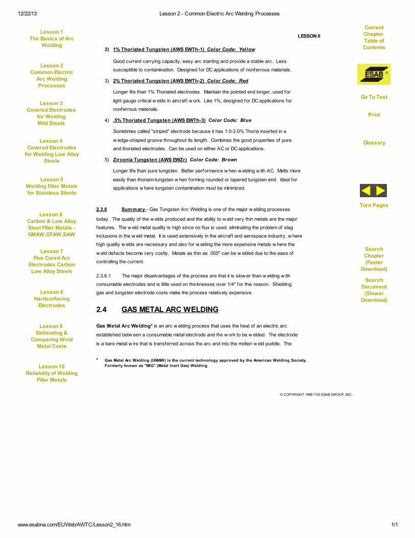
2.3.6 Summary - Gas Tungsten Arc Welding is one of the major w elding processes
today. The quality of the w elds produced and the ability to w eld very thin metals are the major
features. The w eld metal quality is high since no f lux is used, eliminating the problem of slag
inclusions in the w eld metal. It is used extensively in the aircraft and aerospace industry, w here
high quality w elds are necessary and also for w elding the more expensive metals w here the
w eld defects become very costly. Metals as thin as .005" can be w elded due to the ease of
controlling the current.
2.3.6.1 The major disadvantages of the process are that it is slow er than w elding w ith
consumable electrodes and is little used on thicknesses over 1/4" for this reason. Shielding
gas and tungsten electrode costs make the process relatively expensive.
2.4 GAS METAL ARC WELDING
Gas Metal Arc Welding* is an arc w elding process that uses the heat of an electric arc
established betw een a consumable metal electrode and the w ork to be w elded. The electrode
is a bare metal w ire that is transferred across the arc and into the molten w eld puddle. The
* Gas Metal Arc Welding (GMAW) is the current technology approved by the American Welding Society.
Formerly known as "MIG" (Metal Inert Gas) Welding.
Lesson 1The Basics of Arc
Welding
Current
Chapter Table of
Contents
Lesson 2Common Electric
Arc Welding
Processes
Lesson 3
Covered Electrodes
for WeldingMild Steels
Lesson 4
Covered Electrodes
for Welding Low AlloySteels
Go To Test
Lesson 5
Welding Filler Metalsfor Stainless Steels
Lesson 6
Carbon & Low AlloySteel Filler Metals -GMAW,GTAW,SAW
Glossary
Lesson 7
Flux Cored ArcElectrodes CarbonLow Alloy Steels
SearchChapter
(FasterDownload)
Lesson 8Hardsurfacing
Electrodes
Turn Pages
Lesson 9
Estimating &Comparing Weld
Metal Costs
SearchDocument
(SlowerDownload)
Lesson 10
Reliability of Welding
Filler Metals
12/22/13 Lesson 2 - Common Electric Arc Welding Processes
www.esabna.com/EUWeb/AWTC/Lesson2_17.htm 1/1
© COPYRIGHT 1998 THE ESAB GROUP, INC.
LESSON II
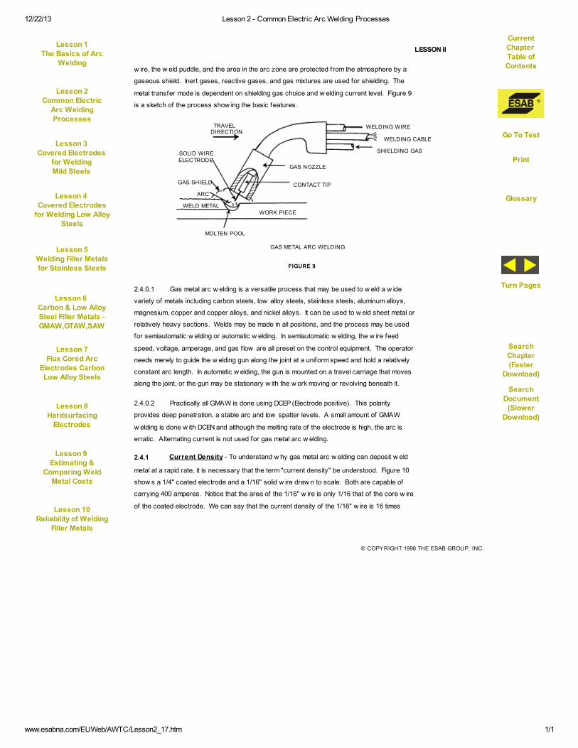
w ire, the w eld puddle, and the area in the arc zone are protected from the atmosphere by a
gaseous shield. Inert gases, reactive gases, and gas mixtures are used for shielding. The
metal transfer mode is dependent on shielding gas choice and w elding current level. Figure 9
is a sketch of the process show ing the basic features.
FIGURE 9
WELDING WIRE
WELDING CABLE
SHIELDING GAS
GAS NOZZLE
CONTACT TIP
WORK PIECE
MOLTEN POOL
WELD METAL
ARC
GAS SHIELD
SOLID WIREELECTRODE
TRAVELDIRECTION
GAS METAL ARC WELDING
2.4.0.1 Gas metal arc w elding is a versatile process that may be used to w eld a w ide
variety of metals including carbon steels, low alloy steels, stainless steels, aluminum alloys,
magnesium, copper and copper alloys, and nickel alloys. It can be used to w eld sheet metal or
relatively heavy sections. Welds may be made in all positions, and the process may be used
for semiautomatic w elding or automatic w elding. In semiautomatic w elding, the w ire feed
speed, voltage, amperage, and gas f low are all preset on the control equipment. The operator
needs merely to guide the w elding gun along the joint at a uniform speed and hold a relatively
constant arc length. In automatic w elding, the gun is mounted on a travel carriage that moves
along the joint, or the gun may be stationary w ith the w ork moving or revolving beneath it.
2.4.0.2 Practically all GMAW is done using DCEP (Electrode positive). This polarity
provides deep penetration, a stable arc and low spatter levels. A small amount of GMAW
w elding is done w ith DCEN and although the melting rate of the electrode is high, the arc is
erratic. Alternating current is not used for gas metal arc w elding.
2.4.1 Current Density - To understand w hy gas metal arc w elding can deposit w eld
metal at a rapid rate, it is necessary that the term "current density" be understood. Figure 10
show s a 1/4" coated electrode and a 1/16" solid w ire draw n to scale. Both are capable of
carrying 400 amperes. Notice that the area of the 1/16" w ire is only 1/16 that of the core w ire
of the coated electrode. We can say that the current density of the 1/16" w ire is 16 times
Current
Chapter Table of
Contents
Lesson 1The Basics of Arc
Welding
Lesson 2Common Electric
Arc Welding
Processes
Lesson 3
Covered Electrodes
for WeldingMild Steels
Go To Test
Lesson 4
Covered Electrodes
for Welding Low AlloySteels
Lesson 5
Welding Filler Metalsfor Stainless Steels
Glossary
Lesson 6
Carbon & Low AlloySteel Filler Metals -GMAW,GTAW,SAW
SearchChapter
(FasterDownload)
Lesson 7
Flux Cored ArcElectrodes CarbonLow Alloy Steels
Turn Pages
Lesson 8Hardsurfacing
Electrodes
SearchDocument
(SlowerDownload)
Lesson 9
Estimating &Comparing Weld
Metal Costs
Lesson 10
Reliability of Welding
Filler Metals

12/22/13 Lesson 2 - Common Electric Arc Welding Processes
www.esabna.com/EUWeb/AWTC/Lesson2_18.htm 1/1
© COPYRIGHT 1998 THE ESAB GROUP, INC.
LESSON II
greater than the current density
of the 1/4" w ire at equal w elding
currents. The resultant melt-off
rate of the solid w ire is very high.
If w e w ere to increase the current
through the 1/4" coated
electrode to increase the current
density, the resistance heating
through the 14" electrode length w ould be
excessive, and the rod w ould become so
hot that the coating w ould crack, rendering
it useless. The 1/16" w ire carries the high
current a distance of less than 3/4", the
approximate distance from the end of the contact tip to the arc.
2.4.2 Metal Transfer Modes
2.4.2.1 Spray transfer is a high current density process that rapidly deposits w eld metal in
droplets smaller than the electrode diameter. They are propelled in a straight line from the
center of the electrode. A shielding gas mixture of Argon w ith 1% to 2% Oxygen is used for
w elding mild and low alloy steel, and pure Argon or Argon-Helium mixtures are used for w eld-
ing aluminum, magnesium, copper, and nickel alloys. Welding current at w hich spray transfer
FIGURE 10
AREA = .049 SQ. IN.
AREA = .0031 SQ. IN.CORE WIRE
FLUXCOATING
COATED ELECTRODE
RELATIVE SIZE OF ELECTRODES FOR WELDING AT 400 AMPS
SOLID WIRE
1/4"
1/16"
.049 ÷ .0031 = 16
AA × 16
FIGURE 11
SPRAYTRANSFER
GLOBULARTRANSFER
PULSETRANSFER
MODES OF METAL TRANSFER
1 2 3SHORT CIRCUITING ARC METAL TRANSFER
takes place is relatively high and w ill vary w ith the metal being w elded, electrode diameter, and
the shielding gas being used. Deposition rates are high and w elding is usually limited to the
flat or horizontal f illet position. See Figure 11.
Current
Chapter Table of
Contents
Lesson 1The Basics of Arc
Welding
Lesson 2Common Electric
Arc Welding
Processes
Lesson 3
Covered Electrodes
for WeldingMild Steels
Go To Test
Lesson 4
Covered Electrodes
for Welding Low AlloySteels
Lesson 5
Welding Filler Metalsfor Stainless Steels
Glossary
Lesson 6
Carbon & Low AlloySteel Filler Metals -GMAW,GTAW,SAW
SearchChapter
(FasterDownload)
Lesson 7
Flux Cored ArcElectrodes CarbonLow Alloy Steels
Turn Pages
Lesson 8Hardsurfacing
Electrodes
SearchDocument
(SlowerDownload)
Lesson 9
Estimating &Comparing Weld
Metal Costs
Lesson 10
Reliability of Welding
Filler Metals
12/22/13 Lesson 2 - Common Electric Arc Welding Processes
www.esabna.com/EUWeb/AWTC/Lesson2_19.htm 1/1
© COPYRIGHT 1998 THE ESAB GROUP, INC.
LESSON II
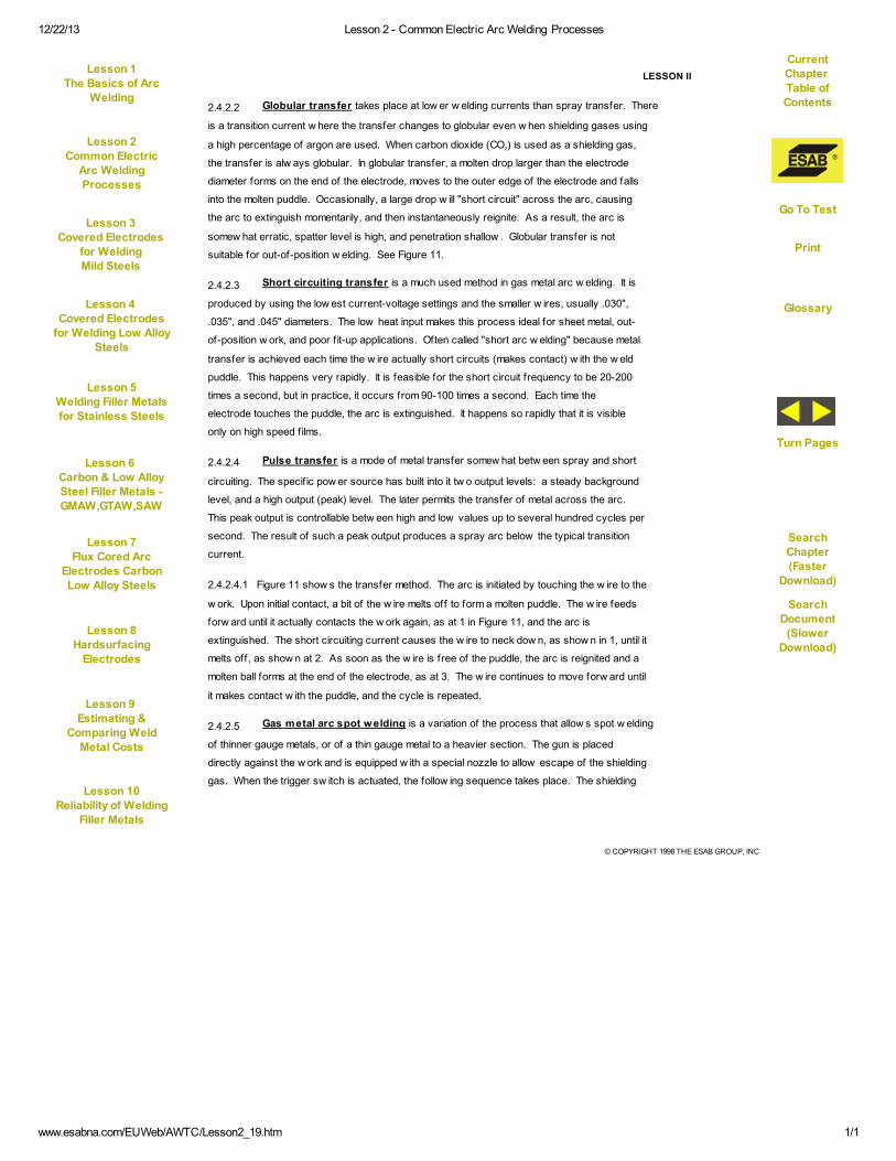
2.4.2.2 Globular transfer takes place at low er w elding currents than spray transfer. There
is a transition current w here the transfer changes to globular even w hen shielding gases using
a high percentage of argon are used. When carbon dioxide (CO2) is used as a shielding gas,
the transfer is alw ays globular. In globular transfer, a molten drop larger than the electrode
diameter forms on the end of the electrode, moves to the outer edge of the electrode and falls
into the molten puddle. Occasionally, a large drop w ill "short circuit" across the arc, causing
the arc to extinguish momentarily, and then instantaneously reignite. As a result, the arc is
somew hat erratic, spatter level is high, and penetration shallow . Globular transfer is not
suitable for out-of-position w elding. See Figure 11.
2.4.2.3 Short circuiting transfer is a much used method in gas metal arc w elding. It is
produced by using the low est current-voltage settings and the smaller w ires, usually .030",
.035", and .045" diameters. The low heat input makes this process ideal for sheet metal, out-
of-position w ork, and poor f it-up applications. Often called "short arc w elding" because metal
transfer is achieved each time the w ire actually short circuits (makes contact) w ith the w eld
puddle. This happens very rapidly. It is feasible for the short circuit frequency to be 20-200
times a second, but in practice, it occurs from 90-100 times a second. Each time the
electrode touches the puddle, the arc is extinguished. It happens so rapidly that it is visible
only on high speed f ilms.
2.4.2.4 Pulse transfer is a mode of metal transfer somew hat betw een spray and short
circuiting. The specif ic pow er source has built into it tw o output levels: a steady background
level, and a high output (peak) level. The later permits the transfer of metal across the arc.
This peak output is controllable betw een high and low values up to several hundred cycles per
second. The result of such a peak output produces a spray arc below the typical transition
current.
2.4.2.4.1 Figure 11 show s the transfer method. The arc is initiated by touching the w ire to the
w ork. Upon initial contact, a bit of the w ire melts off to form a molten puddle. The w ire feeds
forw ard until it actually contacts the w ork again, as at 1 in Figure 11, and the arc is
extinguished. The short circuiting current causes the w ire to neck dow n, as show n in 1, until it
melts off, as show n at 2. As soon as the w ire is free of the puddle, the arc is reignited and a
molten ball forms at the end of the electrode, as at 3. The w ire continues to move forw ard until
it makes contact w ith the puddle, and the cycle is repeated.
2.4.2.5 Gas metal arc spot welding is a variation of the process that allow s spot w elding
of thinner gauge metals, or of a thin gauge metal to a heavier section. The gun is placed
directly against the w ork and is equipped w ith a special nozzle to allow escape of the shielding
gas. When the trigger sw itch is actuated, the follow ing sequence takes place. The shielding
Current
Chapter Table of
Contents
Lesson 1The Basics of Arc
Welding
Lesson 2Common Electric
Arc Welding
Processes
Lesson 3
Covered Electrodes
for WeldingMild Steels
Go To Test
Lesson 4
Covered Electrodes
for Welding Low AlloySteels
Lesson 5
Welding Filler Metalsfor Stainless Steels
Glossary
Lesson 6
Carbon & Low AlloySteel Filler Metals -GMAW,GTAW,SAW
SearchChapter
(FasterDownload)
Lesson 7
Flux Cored ArcElectrodes CarbonLow Alloy Steels
Turn Pages
Lesson 8Hardsurfacing
Electrodes
SearchDocument
(SlowerDownload)
Lesson 9
Estimating &Comparing Weld
Metal Costs
Lesson 10
Reliability of Welding
Filler Metals

12/22/13 Lesson 2 - Common Electric Arc Welding Processes
www.esabna.com/EUWeb/AWTC/Lesson2_20.htm 1/1
© COPYRIGHT 1998 THE ESAB GROUP, INC.
LESSON II
gas f low s for a short interval before w ire feeding starts; w ire feeding starts; the arc is initiated
and continues for a preset time (usually a few seconds). The w elding current and w ire feeding
stops, and the shielding gas f low s for a short interval before it automatically stops. The
process is also useful for tacking w elding pieces in position prior to running the f inal w eld
bead.
2.4.3 EQUIPMENT AND OPERATION - The equipment used for gas metal arc w elding
is more complicated than that required for shielded metal arc w elding. Initial cost is relatively
high, but the cost is rapidly amortized due to the savings in labor and overhead achieved by
the rapid w eld metal deposition.
2.4.3.1 The equipment necessary for gas metal arc w elding is listed below :
1) Pow er source
2) Wire feeder
3) Welding gun
4) Shielding gas supply
5) Solid electrode w ire
6) Protective equipment
2.4.3.2 The basic equipment necessary for semiautomatic gas metal arc w elding is show n
in Figure 12.
FIGURE 12
FLOWMETERREGULATOR
SHIELDINGGAS
POWERSOURCE
GROUND CABLEWORK
WELDING GUN
WELD CABLE
115V CONTACTOR
MAGNETIC
VALVE
TRIGGERCONTROL LEAD
FEED ROLLS
GAS HOSE
WIRE FEEDER
WIRE SPOOL
+ _
SCHEMATIC DIAGRAM SEMI-AUTOMATIC GMAW EQUIPMENT
Lesson 1The Basics of Arc
Welding
Current
Chapter Table of
Contents
Lesson 2Common Electric
Arc Welding
Processes
Lesson 3
Covered Electrodes
for WeldingMild Steels
Lesson 4
Covered Electrodes
for Welding Low AlloySteels
Go To Test
Lesson 5
Welding Filler Metalsfor Stainless Steels
Lesson 6
Carbon & Low AlloySteel Filler Metals -GMAW,GTAW,SAW
Glossary
Lesson 7
Flux Cored ArcElectrodes CarbonLow Alloy Steels
SearchChapter
(FasterDownload)
Lesson 8Hardsurfacing
Electrodes
Turn Pages
Lesson 9
Estimating &Comparing Weld
Metal Costs
SearchDocument
(SlowerDownload)
Lesson 10
Reliability of Welding
Filler Metals

12/22/13 Lesson 2 - Common Electric Arc Welding Processes
www.esabna.com/EUWeb/AWTC/Lesson2_21.htm 1/1
© COPYRIGHT 1998 THE ESAB GROUP, INC.
LESSON II
2.4.4 Power Source - A direct current, constant v oltage power source is recommended
for gas metal arc w elding. It may be a transformer-rectif ier or a rotary type unit. The low er
open circuit voltage and self-correcting arc length feature, as described in Lesson I, makes it
most suitable. Constant voltage pow er sources used for spray transfer w elding and for f lux
cored electrode w elding (to be covered later) are the same. How ever, if the unit is to be used
for short-circuiting arc
w elding, it must have
"slope" or slope control.
Slope control is a
means of limiting the
high short-circuit current
that is characteristic of
this type w elder. Figure
13 show s the effect of
slope on the short-
circuiting current.
2.4.4.1 If w e w ere
short-arc w elding at
approximately 150 amperes
and 18 volts, as show n in Figure 13,
and had no slope components in the pow er source, the current at short-circuit or w hen the w ire
touches the w ork, w ould be over 1400 amperes. At this high current, a good length of the w ire
w ould literally explode off the end, cause much spatter, and the arc w ould be erratic. With the
slope components in the circuit, the short-circuiting current is in the neighborhood of 400
amperes, and the molten ball is sort of pinched off the end of the w ire more gently. For those
w ith an electrical background, it might be added that in some machines, slope is achieved by
adding a reactor in the AC secondary of the pow er source. In others, a slope resistor is added
in the DC output portion of the circuit. Slope may be adjustable for varying w ire diameters or it
may be f ixed, giving a good average value for .035" and .045" diameter w ires, the tw o most
popular sizes.
2.4.4.2 Another factor inf luencing the arc in short-circuiting w elding is the rate that the
amperage reaches the short-circuiting current level. Using the example in Figure 13, w e know
that the current goes from 150 amperes to 400 amperes during each shorting period. If w e
w ere to plot the current rise on a graph, as in Figure 14, w e w ould see that the current rise if
very rapid, as show n by the broken line.
FIGURE 13
25
20
15
10
5
200 400 600 800 1000 1200 1400
OPERATING POINT
CONSTANT VOLTAGE V/A CURVE
SHORT CIRCUITINGCURRENT NO SLOPE
SHORT CIRCUITING CURRENT
WITH SLOPE
EFFECT OF SLOPE ON SHORT CIRCUITING CURRENT
VO
LT
S
Current
Chapter Table of
Contents
Lesson 1The Basics of Arc
Welding
Lesson 2Common Electric
Arc Welding
Processes
Lesson 3
Covered Electrodes
for WeldingMild Steels
Go To Test
Lesson 4
Covered Electrodes
for Welding Low AlloySteels
Lesson 5
Welding Filler Metalsfor Stainless Steels
Glossary
Lesson 6
Carbon & Low AlloySteel Filler Metals -GMAW,GTAW,SAW
SearchChapter
(FasterDownload)
Lesson 7
Flux Cored ArcElectrodes CarbonLow Alloy Steels
Turn Pages
Lesson 8Hardsurfacing
Electrodes
SearchDocument
(SlowerDownload)
Lesson 9
Estimating &Comparing Weld
Metal Costs
Lesson 10
Reliability of Welding
Filler Metals
12/22/13 Lesson 2 - Common Electric Arc Welding Processes
www.esabna.com/EUWeb/AWTC/Lesson2_22.htm 1/1
© COPYRIGHT 1998 THE ESAB GROUP, INC.
LESSON II
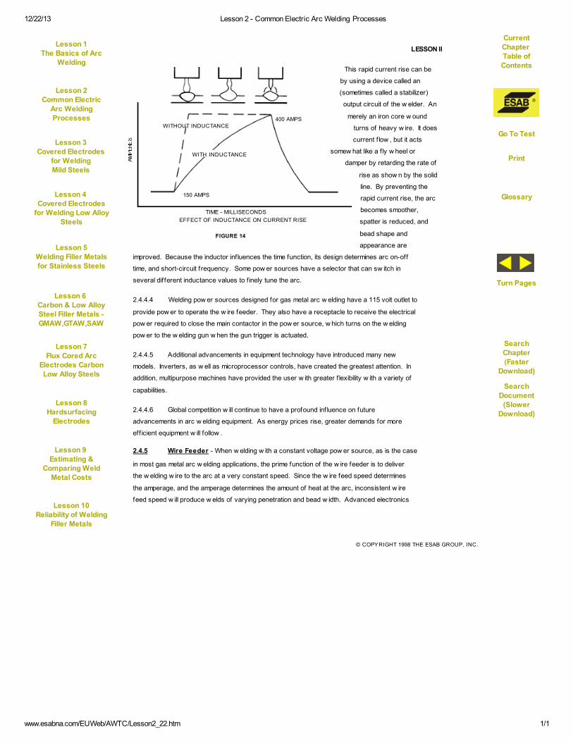
This rapid current rise can be
by using a device called an
(sometimes called a stabilizer)
output circuit of the w elder. An
merely an iron core w ound
turns of heavy w ire. It does
current f low , but it acts
somew hat like a f ly w heel or
damper by retarding the rate of
rise as show n by the solid
line. By preventing the
rapid current rise, the arc
becomes smoother,
spatter is reduced, and
bead shape and
appearance are
improved. Because the inductor inf luences the time function, its design determines arc on-off
time, and short-circuit frequency. Some pow er sources have a selector that can sw itch in
several different inductance values to f inely tune the arc.
2.4.4.4 Welding pow er sources designed for gas metal arc w elding have a 115 volt outlet to
provide pow er to operate the w ire feeder. They also have a receptacle to receive the electrical
pow er required to close the main contactor in the pow er source, w hich turns on the w elding
pow er to the w elding gun w hen the gun trigger is actuated.
2.4.4.5 Additional advancements in equipment technology have introduced many new
models. Inverters, as w ell as microprocessor controls, have created the greatest attention. In
addition, multipurpose machines have provided the user w ith greater f lexibility w ith a variety of
capabilities.
2.4.4.6 Global competition w ill continue to have a profound influence on future
advancements in arc w elding equipment. As energy prices rise, greater demands for more
eff icient equipment w ill follow .
2.4.5 Wire Feeder - When w elding w ith a constant voltage pow er source, as is the case
in most gas metal arc w elding applications, the prime function of the w ire feeder is to deliver
the w elding w ire to the arc at a very constant speed. Since the w ire feed speed determines
the amperage, and the amperage determines the amount of heat at the arc, inconsistent w ire
feed speed w ill produce w elds of varying penetration and bead w idth. Advanced electronics
FIGURE 14
TIME - MILLISECONDS
EFFECT OF INDUCTANCE ON CURRENT RISE
400 AMPSWITHOUT INDUCTANCE
WITH INDUCTANCE
150 AMPS
Current
Chapter Table of
Contents
Lesson 1The Basics of Arc
Welding
Lesson 2Common Electric
Arc Welding
Processes
Lesson 3
Covered Electrodes
for WeldingMild Steels
Go To Test
Lesson 4
Covered Electrodes
for Welding Low AlloySteels
Lesson 5
Welding Filler Metalsfor Stainless Steels
Glossary
Lesson 6
Carbon & Low AlloySteel Filler Metals -GMAW,GTAW,SAW
SearchChapter
(FasterDownload)
Lesson 7
Flux Cored ArcElectrodes CarbonLow Alloy Steels
Turn Pages
Lesson 8Hardsurfacing
Electrodes
SearchDocument
(SlowerDownload)
Lesson 9
Estimating &Comparing Weld
Metal Costs
Lesson 10
Reliability of Welding
Filler Metals

12/22/13 Lesson 2 - Common Electric Arc Welding Processes
www.esabna.com/EUWeb/AWTC/Lesson2_23.htm 1/1
© COPYRIGHT 1998 THE ESAB GROUP, INC.
LESSON II
technology makes it possible to design motor speed controls that w ill produce the same
speed, even though the load on the motor varies or the input voltage to the motor may f luctuate.
2.4.5.1 A limited amount of gas metal arc w elding is performed w ith constant current type
pow er sources. In this case, the motor speed automatically varies to increase or decrease the
w ire feed speed as the arc length varies to maintain a constant voltage.
2.4.5.2 The w ire feeder also controls the main contactor in the pow er source for safety
reasons. This assures that the w elding w ire w ill only be energized w hen the sw itch on the
w elding gun is depressed.
2.4.5.3 The f low of shielding gas is controlled by a solenoid valve (magnetic valve) in the
w ire feeder to turn the shielding gas on and off w hen the gun sw itch is actuated. Most feeders
utilize a dynamic breaking circuit to quickly stop the motor at the end of a w eld to prevent a
long length of w ire protruding from the gun w hen the w eld is terminated. Most feeders have a
burn-back circuit that allow s the w elding current to stay on for a short period of time after w ire
feeding has stopped, to allow the w ire to burn back exactly the right amount for the next arc
initiation.
2.4.5.4 The feed rolls, sometimes called drive rolls, pull the w ire off the spool or reel, and
push it through a feed cable or conduit to the w elding gun. These rolls must usually be
changed to accommodate each different w ire diameter, although some rolls are designed to
feed a combination of sizes.
2.4.6 Welding Gun - The function of the w elding gun, sometimes referred to as a torch, is
to deliver the w elding w ire, w elding current, and shielding gas to the w elding arc. Guns are
available for semi-automatic operation and for automatic operation, w here they are f ixed in the
automatic w elding head.
2.4.6.1 Guns for GMAW have several characteristics in common. All have a copper alloy
shielding gas nozzle, that delivers the gas to the arc area in a nonturbulent, angular pattern to
prevent aspiration of air. The nozzle may be w ater cooled for semiautomatic w elding at high
amperage and for automatic w elding w here the arc time is of long duration. Welding current is
transferred to the w elding w ire as the w ire travels through the contact tip or contact tube
located inside the gas nozzle (Refer to Figure 9). The hole in the contact tip through w hich the
w ire passes is only a few thousandths of an inch larger than the w ire diameter. A w orn contact
tip w ill result in an erratic arc due to poor current transfer. Figure 15 show s a few different
semiautomatic gun configurations that are commonly used for GMAW.
Current
Chapter Table of
Contents
Lesson 1The Basics of Arc
Welding
Lesson 2Common Electric
Arc Welding
Processes
Lesson 3
Covered Electrodes
for WeldingMild Steels
Go To Test
Lesson 4
Covered Electrodes
for Welding Low AlloySteels
Lesson 5
Welding Filler Metalsfor Stainless Steels
Glossary
Lesson 6
Carbon & Low AlloySteel Filler Metals -GMAW,GTAW,SAW
SearchChapter
(FasterDownload)
Lesson 7
Flux Cored ArcElectrodes CarbonLow Alloy Steels
Turn Pages
Lesson 8Hardsurfacing
Electrodes
SearchDocument
(SlowerDownload)
Lesson 9
Estimating &Comparing Weld
Metal Costs
Lesson 10
Reliability of Welding
Filler Metals
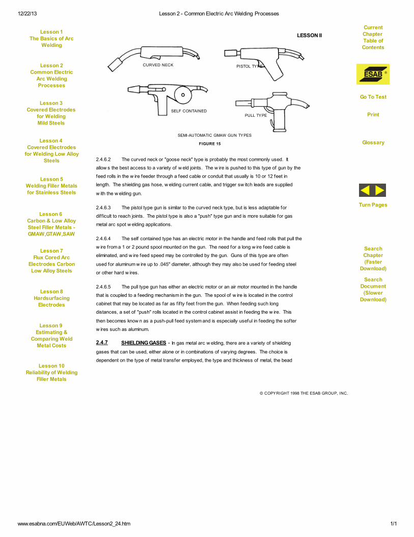
12/22/13 Lesson 2 - Common Electric Arc Welding Processes
www.esabna.com/EUWeb/AWTC/Lesson2_24.htm 1/1
© COPYRIGHT 1998 THE ESAB GROUP, INC.
LESSON II
2.4.6.2 The curved neck or "goose neck" type is probably the most commonly used. It
allow s the best access to a variety of w eld joints. The w ire is pushed to this type of gun by the
feed rolls in the w ire feeder through a feed cable or conduit that usually is 10 or 12 feet in
length. The shielding gas hose, w elding current cable, and trigger sw itch leads are supplied
w ith the w elding gun.
2.4.6.3 The pistol type gun is similar to the curved neck type, but is less adaptable for
diff icult to reach joints. The pistol type is also a "push" type gun and is more suitable for gas
metal arc spot w elding applications.
2.4.6.4 The self contained type has an electric motor in the handle and feed rolls that pull the
w ire from a 1 or 2 pound spool mounted on the gun. The need for a long w ire feed cable is
eliminated, and w ire feed speed may be controlled by the gun. Guns of this type are often
used for aluminum w ire up to .045" diameter, although they may also be used for feeding steel
or other hard w ires.
2.4.6.5 The pull type gun has either an electric motor or an air motor mounted in the handle
that is coupled to a feeding mechanism in the gun. The spool of w ire is located in the control
cabinet that may be located as far as f if ty feet from the gun. When feeding such long
distances, a set of "push" rolls located in the control cabinet assist in feeding the w ire. This
then becomes know n as a push-pull feed system and is especially useful in feeding the softer
w ires such as aluminum.
2.4.7 SHIELDING GASES - In gas metal arc w elding, there are a variety of shielding
gases that can be used, either alone or in combinations of varying degrees. The choice is
dependent on the type of metal transfer employed, the type and thickness of metal, the bead
CURVED NECK PISTOL TYPE
SELF CONTAINEDPULL TYPE
SEMI-AUTOMATIC GMAW GUN TYPES
FIGURE 15
Current
Chapter Table of
Contents
Lesson 1The Basics of Arc
Welding
Lesson 2Common Electric
Arc Welding
Processes
Lesson 3
Covered Electrodes
for WeldingMild Steels
Go To Test
Lesson 4
Covered Electrodes
for Welding Low AlloySteels
Lesson 5
Welding Filler Metalsfor Stainless Steels
Glossary
Lesson 6
Carbon & Low AlloySteel Filler Metals -GMAW,GTAW,SAW
SearchChapter
(FasterDownload)
Lesson 7
Flux Cored ArcElectrodes CarbonLow Alloy Steels
Turn Pages
Lesson 8Hardsurfacing
Electrodes
SearchDocument
(SlowerDownload)
Lesson 9
Estimating &Comparing Weld
Metal Costs
Lesson 10
Reliability of Welding
Filler Metals

12/22/13 Lesson 2 - Common Electric Arc Welding Processes
www.esabna.com/EUWeb/AWTC/Lesson2_25.htm 1/1
© COPYRIGHT 1998 THE ESAB GROUP, INC.
LESSON II
profile (See Figure 16), penetration, and speed of w elding. In our discussion, w e w ill deal w ith
the more common choices used for the various transfer processes.
2.4.7.1 Short Circuiting Transfer - Straight carbon dioxide (CO2) is often used for short
circuiting arc w elding because of its low cost. The deep penetration usually associated w ith
CO2 is minimized because of the low amperage and voltage settings used w ith this process.
Compared to other gas mixes, CO2 w ill produce a harsher arc and therefore, greater spatter
levels. Usually, this is minimized by maintaining a short arc length and by careful adjustment of
the pow er supply inductance. The temperatures reached in w elding w ill cause carbon dioxide
to decompose into carbon monoxide and oxygen. To reduce the possibility of porosity caused
by entrapped oxygen in the w eld metal, it is w ise to use electrodes that contain deoxidizing
elements, such as silicon and manganese. If the current is increased above the short circuiting
range, the use of carbon dioxide tends to produce a globular transfer.
2.4.7.1.1 Mixing argon in proportions of 50-75% w ith carbon dioxide w ill produce a smoother
arc and reduce spatter levels. It w ill also w iden the bead profile, reduce penetration, and
encourage "w etting". Wetting, i.e., a uniform fusion, along w ith joining edges of the base metal
and the w eld metal, minimizes the w eld imperfection know n as undercutting (See Figure 17).
FERROUS METALS NON-FERROUS METALS
CO2 ARGON + CO2 ARGON + O2 ARGON HELIUM
BEAD PROFILE
FIGURE 16
FIGURE 17
UNDERCUT WETTING
2.4.7.1.2 The 75% Argon/25 CO2 mixture is often chosen for short circuit w elding of thin
sections, w hereas the 50-50 combination w orks w ell on thicker sections.
2.4.7.1.3 It should be noted that shielding gases can affect the metallurgy of the w eld metal.
As an example, a combination of argon and carbon dioxide may be used for w elding stainless
steel, but as the carbon dioxide breaks dow n, excessive carbon may be transferred into the
Current
Chapter Table of
Contents
Lesson 1The Basics of Arc
Welding
Lesson 2Common Electric
Arc Welding
Processes
Lesson 3
Covered Electrodes
for WeldingMild Steels
Go To Test
Lesson 4
Covered Electrodes
for Welding Low AlloySteels
Lesson 5
Welding Filler Metalsfor Stainless Steels
Glossary
Lesson 6
Carbon & Low AlloySteel Filler Metals -GMAW,GTAW,SAW
SearchChapter
(FasterDownload)
Lesson 7
Flux Cored ArcElectrodes CarbonLow Alloy Steels
Turn Pages
Lesson 8Hardsurfacing
Electrodes
SearchDocument
(SlowerDownload)
Lesson 9
Estimating &Comparing Weld
Metal Costs
Lesson 10
Reliability of Welding
Filler Metals

12/22/13 Lesson 2 - Common Electric Arc Welding Processes
www.esabna.com/EUWeb/AWTC/Lesson2_26.htm 1/1
© COPYRIGHT 1998 THE ESAB GROUP, INC.
LESSON II
w eld metal. Corrosion resistance in stainless steel is reduced as the carbon content
increases. To counteract this possibility, a less reactive mixture of 90% helium - 7-1/2% argon
- 2-1/2% CO2 is sometimes chosen. This combination, know n as a trimix, provides good arc
stability and w etting.
2.4.7.2 Spray Arc Transfer - Pure argon produces a deep constricted penetration at the
center of the bead w ith much shallow er penetration at the edges (Figure 16). Argon performs
w ell on nonferrous metals, but w hen used on ferrous metals, the transfer is somew hat erratic
w ith the tendency for the w eld metal to move aw ay from the center line. To make argon suit-
able for spray transfer on ferrous metals, small additions of 1 to 5% oxygen have proven to
provide remarkable improvements. The arc stabilizes, becomes less spattery, and the w eld
metal w ets out nicely. If the percentage of argon falls below 80%, it is impossible to achieve
true spray transfer.
2.4.7.2.1 Pure helium or combinations of helium and argon are used for w elding nonferrous
metals. The bead profile w ill broaden as the concentration of helium increases.
2.4.7.3 Pulse Spray Transfer - The selection of shielding gas must be adequate enough to
support a spray transfer. Material type, thickness, and w elding position are essential variables
in selecting a particular shielding gas. The follow ing is a list of recommended gases:
Carbon Steel Argon/CO2/O2/He (He less than 50%)
Alloy Steel Argon/CO2/O2/He (He less than 50%)
Stainless Argon/O2/CO2 (CO2 max. 2%)
Copper, Nickel, & Cu-Ni Alloys Argon/Helium
Aluminum Argon/Helium
2.4.8 Electrodes - The solid electrodes used in GMAW are of high purity w hen they come
from the mill. Their chemistry must be closely controlled and some types purposely contain
high levels of deoxidizers for use w ith CO2 shielding.
2.4.8.1 The electrode manufacturer draw s dow n the electrode to a f inished diameter that,
w ith GMAW, is usually quite small. Diameters from .030" thru 1/16" are common.
2.4.8.2 Most steel GMAW electrodes are copper plated as a means of protecting the
surface. The copper inhibits rusting, provides smooth feeding, and helps electrical
conductivity.
2.4.8.3 Information on types and classif ications w ill be covered in a future lesson.
Current
Chapter Table of
Contents
Lesson 1The Basics of Arc
Welding
Lesson 2Common Electric
Arc Welding
Processes
Lesson 3
Covered Electrodes
for WeldingMild Steels
Go To Test
Lesson 4
Covered Electrodes
for Welding Low AlloySteels
Lesson 5
Welding Filler Metalsfor Stainless Steels
Glossary
Lesson 6
Carbon & Low AlloySteel Filler Metals -GMAW,GTAW,SAW
SearchChapter
(FasterDownload)
Lesson 7
Flux Cored ArcElectrodes CarbonLow Alloy Steels
Turn Pages
Lesson 8Hardsurfacing
Electrodes
SearchDocument
(SlowerDownload)
Lesson 9
Estimating &Comparing Weld
Metal Costs
Lesson 10
Reliability of Welding
Filler Metals

12/22/13 Lesson 2 - Common Electric Arc Welding Processes
www.esabna.com/EUWeb/AWTC/Lesson2_27.htm 1/1
© COPYRIGHT 1998 THE ESAB GROUP, INC.
LESSON II
2.5 FLUX CORED ARC WELDING
Flux Cored Arc Welding (FCAW) is quite similar to GMAW as far as operation and
equipment are concerned. The major difference is that FCAW utilizes an electrode that is very
different from the solid electrode used in GMAW. The f lux cored electrode is a fabricated
electrode and as the name implies, f lux material is deposited into its core. The f lux cored
electrode begins as a f lat metal strip that is formed first into a "U" shape. Flux and alloying
elements are deposited into the "U" and then the shape is closed into a tubular configuration
by a series of forming rolls.
2.5.0.1 The f lux cored electrode is a continuous electrode that is fed into the arc w here it is
melted and transferred into the molten puddle. As in GMAW, the f lux cored process depends
on a gas shield to protect the w eld zone from detrimental atmospheric contamination. With
FCAW, there are tw o primary w ays this is accomplished (See Figure 18). The gas is either
applied externally, in w hich case the electrode is referred to as a gas shielded f lux cored
electrode, or it is generated from the decomposition of gas forming ingredients contained in
the electrode's core. In this instance, the electrode is know n as a self-shielding f lux cored
electrode. In addition to the gas shield, the f lux cored electrode produces a slag covering for
further protection of the w eld metal as it cools. The slag is manually removed w ith a w ire brush
or chipping hammer.
2.5.1 Self Shielded Process - The main advantage of the self shielding method is that
its operation is somew hat simplif ied because of the absence of external shielding equipment.
FIGURE 18
GAS CUP
GAS SHIELD
FLUX CORE
GAS SHIELDED
CONTACT TIP
INSULATEDGUIDE TUBE
SELF SHIELDED
CONTACT TIP
FLUX CORE
FLUX-CORED ARC WELDING
Current
Chapter Table of
Contents
Lesson 1The Basics of Arc
Welding
Lesson 2Common Electric
Arc Welding
Processes
Lesson 3
Covered Electrodes
for WeldingMild Steels
Go To Test
Lesson 4
Covered Electrodes
for Welding Low AlloySteels
Lesson 5
Welding Filler Metalsfor Stainless Steels
Glossary
Lesson 6
Carbon & Low AlloySteel Filler Metals -GMAW,GTAW,SAW
SearchChapter
(FasterDownload)
Lesson 7
Flux Cored ArcElectrodes CarbonLow Alloy Steels
Turn Pages
Lesson 8Hardsurfacing
Electrodes
SearchDocument
(SlowerDownload)
Lesson 9
Estimating &Comparing Weld
Metal Costs
Lesson 10
Reliability of Welding
Filler Metals

12/22/13 Lesson 2 - Common Electric Arc Welding Processes
www.esabna.com/EUWeb/AWTC/Lesson2_28.htm 1/1
© COPYRIGHT 1998 THE ESAB GROUP, INC.
LESSON II
Although self shielding electrodes have been developed for w elding low alloy and stainless
steels, they are most w idely used on mild steels. The self shielding method generally uses a
long electrical stick-out (distance betw een the contact tube and the end of the unmelted elec-
trode) commonly from one to four inches. Electrical resistance is increased w ith the long
extension, preheating the electrode before it is fed into the arc. This enables the electrode to
burn off at a faster rate and increases deposition. The preheating also decreases the heat
available for melting the base metal, resulting in a more shallow penetration than the gas
shielded process.
2.5.1.1 A major draw back of the self shielded process is the metallurgical quality of the
deposited w eld metal. In addition to gaining its shielding ability from gas forming ingredients
in the core, the self shielded electrode contains a high level of deoxidizing and denitrifying
alloys, primarily aluminum, in its core. Although the aluminum performs w ell in neutralizing the
affects of oxygen and nitrogen in the arc zone, its presence in the w eld metal w ill reduce
ductility and impact strength at low temperatures. For this reason, the self shielding method is
usually restricted to less critical applications.
2.5.1.2 The self shielding electrodes are more suitable for w elding in drafty locations than
the gas shielded types. Since the molten f iller metal is on the outside of the f lux, the gases
formed by the decomposing f lux are not totally relied upon to shield the arc from the
atmosphere. The deoxidizing and denitrifying elements in the f lux further help to neutralize the
affects of nitrogen and oxygen present in the w eld zone.
2.5.2 The Gas Shielded Process - A major advantage w ith the shielded f lux cored
electrode is the protective envelope formed by the auxiliary gas shield around the molten
puddle. This envelope effectively excludes the natural gases in the atmosphere w ithout the
need for core ingredients such as aluminum. Because of this more thorough shielding, the
w eld metallurgy is cleaner w hich makes this process suitable for w elding not only mild steels,
but also low alloy steels in a w ide range of strength and impact levels.
2.5.2.1 The gas shielded method uses a shorter electrical stickout than the self shielded
process. Extensions from 1/2" to 3/4" are common on all diameters, and 3/4" to 1-1/2" on
larger diameters. Higher w elding currents are also used w ith this process, enabling high
deposition rates to be reached. The auxiliary shielding helps to reduce the arc energy into a
columnar pattern. The combination of high currents and the action of the shielding gas
contributes to the deep penetration inherent w ith this process. Both spray and globular
transfer are utilized w ith the gas shielded process.
Current
Chapter Table of
Contents
Lesson 1The Basics of Arc
Welding
Lesson 2Common Electric
Arc Welding
Processes
Lesson 3
Covered Electrodes
for WeldingMild Steels
Go To Test
Lesson 4
Covered Electrodes
for Welding Low AlloySteels
Lesson 5
Welding Filler Metalsfor Stainless Steels
Glossary
Lesson 6
Carbon & Low AlloySteel Filler Metals -GMAW,GTAW,SAW
SearchChapter
(FasterDownload)
Lesson 7
Flux Cored ArcElectrodes CarbonLow Alloy Steels
Turn Pages
Lesson 8Hardsurfacing
Electrodes
SearchDocument
(SlowerDownload)
Lesson 9
Estimating &Comparing Weld
Metal Costs
Lesson 10
Reliability of Welding
Filler Metals

12/22/13 Lesson 2 - Common Electric Arc Welding Processes
www.esabna.com/EUWeb/AWTC/Lesson2_29.htm 1/1
© COPYRIGHT 1998 THE ESAB GROUP, INC.
LESSON II
2.5.3 Current Density - Flux cored arc w elding utilizes the same principles of current
density, as explained in section 2.4.1, but there is one signif icant difference betw een the f lux
cored electrode and the solid electrode. With the f lux cored electrode, the granular core
ingredients are poor electrical conductors and therefore, the current is carried primarily
through the outer metal sheathing. When an equal diam-
eter cross section of the tw o are compared (See Figure
19), it is seen that the f lux cored electrode has
a smaller current carrying area than the solid
electrode. This greater concentration of
current in a smaller area increases the
burnoff rate.
2.5.3.1 When all other factors are equal,
the deposition rate of the f lux cored
electrode is somew hat higher than the
solid electrode.
2.5.4 EQUIPMENT - The equipment used for f lux cored arc w elding is the same as
show n previously in Section 2.3.2.2, Figure 12, w ith the exception that the self shielded
method does not need the external gas apparatus.
2.5.4.1 Flux cored arc w elding is done w ith direct current. All of the gas shielded electrodes
are designed for DCEP operation. The self shielded electrodes are either designed
specif ically for DCEN or DCEP.
2.5.5 Power Source - The recommended pow er source is the direct current constant
voltage type. The constant current type can be used but w ith less satisfactory results.
2.5.6 Wire Feeder - The function of the w ire feeder in FCAW is the same as discussed in
the section on GMAW. Since the f lux cored electrode is tubular in construction, precautions
must be taken not to f latten the electrode. To facilitate feeding by means other than pressure
alone, specially designed feed rolls w ith knurled or grooved surfaces are used. Some feeders
use four feed rolls rather than tw o to minimize unit pressure on the electrode.
2.5.7 The Welding Gun - As compared to GMAW, the main difference in FCAW w elding
guns is in those used w ith the self shielding process. The gun is somew hat more compact due
to the absence of an external gas shielding nozzle. Since the self shielding process normally
requires a longer electrode extension, the self shielding gun may have an insulated guide tube
(Refer back to Figure 18) to give stability to the electrode. Water cooled guns are available for
high duty semi-automatic w elding and for automatic w elding.
FIGURE 19
CURRENT PATH
1/16" FLUX-COREDELECTRODE 1/16" SOLID
ELECTRODE
Current
Chapter Table of
Contents
Lesson 1The Basics of Arc
Welding
Lesson 2Common Electric
Arc Welding
Processes
Lesson 3
Covered Electrodes
for WeldingMild Steels
Go To Test
Lesson 4
Covered Electrodes
for Welding Low AlloySteels
Lesson 5
Welding Filler Metalsfor Stainless Steels
Glossary
Lesson 6
Carbon & Low AlloySteel Filler Metals -GMAW,GTAW,SAW
SearchChapter
(FasterDownload)
Lesson 7
Flux Cored ArcElectrodes CarbonLow Alloy Steels
Turn Pages
Lesson 8Hardsurfacing
Electrodes
SearchDocument
(SlowerDownload)
Lesson 9
Estimating &Comparing Weld
Metal Costs
Lesson 10
Reliability of Welding
Filler Metals

12/22/13 Lesson 2 - Common Electric Arc Welding Processes
www.esabna.com/EUWeb/AWTC/Lesson2_30.htm 1/1
© COPYRIGHT 1998 THE ESAB GROUP, INC.
LESSON II
2.5.7.1 Flux cored w elding generates fumes, that for environmental reasons, must be
removed from the w elding area. This is usually done w ith an external exhaust system, but
w elding guns w ith internal fume extractors have been developed. They are heavier than the
regular gun and must be properly maintained so that the extracting mechanism does not
disturb the shielding gas.
2.5.8 SHIELDING GASES - Carbon dioxide is the most w idely used gas for auxiliary
shielding of the f lux cored electrode. The other commonly used gas is a mixture of 75% Argon
and 25% CO2.
2.5.8.1 A carbon dioxide shield produces deep penetration and the transfer is globular. As
previously discussed, CO2 w ill dissociate in the heat of the arc. To counteract this
characteristic, deoxidizing elements are added to the core ingredients of the electrode. The
deoxidizers react to form solid oxide compounds that f loat to the surface as part of the slag
covering.
2.5.8.2 The addition of Argon to CO2 w ill increase the w etting action, produce a smooth arc
arc, and reduce spatter. The transfer is spray-like, and the penetration is somew hat less than
w ith the straight carbon dioxide.
2.5.8.3 While some flux cored electrodes are designed to operate w ell on both the 100%
CO2 or the 75/25 mixture, others are formulated specif ically for the CO2 shield or the Argon/
CO2 mixture. If the recommended gas is not used w ith these electrodes, the w eld chemistry
may be affected. The reason for this is that inert gas, such as Argon, does not react w ith the
other elements; therefore, allow ing them to be transferred across the arc into the w eld metal.
An electrode designed for CO2 shielding contains deoxidizing elements, such as silicon and
manganese. If a high percentage of Argon is used in the shielding medium, a large portion of
these elements may pass into the w eld metal causing the w eld metallurgy to be less ductile
than intended.
2.5.8.3 The opposite happens w ith electrodes formulated for a 75/25 mixture. These
electrodes are usually designed for high yield and tensile strength. If a high percentage of CO2
is used w ith them, the CO2 may react w ith the elements needed to attain these strength levels,
thereby preventing them from passing into the w eld metal.
2.6 SUBMERGED ARC WELDING
Submerged Arc Welding (SAW) is different from the previously explained arc w elding
processes in that the arc is not visible. The arc is submerged beneath loose granular f lux. A
continuous electrode is fed by automatic drive rolls through an electrode holder w here current
Current
Chapter Table of
Contents
Lesson 1The Basics of Arc
Welding
Lesson 2Common Electric
Arc Welding
Processes
Lesson 3
Covered Electrodes
for WeldingMild Steels
Go To Test
Lesson 4
Covered Electrodes
for Welding Low AlloySteels
Lesson 5
Welding Filler Metalsfor Stainless Steels
Glossary
Lesson 6
Carbon & Low AlloySteel Filler Metals -GMAW,GTAW,SAW
SearchChapter
(FasterDownload)
Lesson 7
Flux Cored ArcElectrodes CarbonLow Alloy Steels
Turn Pages
Lesson 8Hardsurfacing
Electrodes
SearchDocument
(SlowerDownload)
Lesson 9
Estimating &Comparing Weld
Metal Costs
Lesson 10
Reliability of Welding
Filler Metals
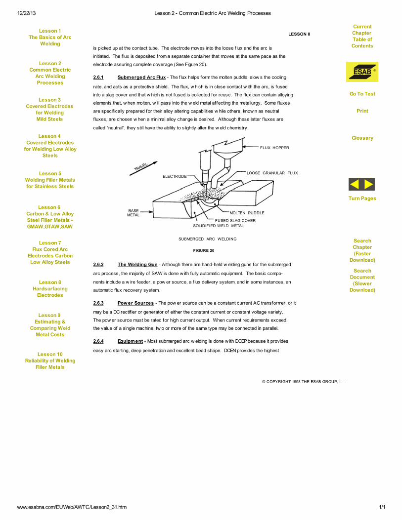
12/22/13 Lesson 2 - Common Electric Arc Welding Processes
www.esabna.com/EUWeb/AWTC/Lesson2_31.htm 1/1
© COPYRIGHT 1998 THE ESAB GROUP, INC.
LESSON II
is picked up at the contact tube. The electrode moves into the loose f lux and the arc is
initiated. The f lux is deposited from a separate container that moves at the same pace as the
electrode assuring complete coverage (See Figure 20).
2.6.1 Submerged Arc Flux - The f lux helps form the molten puddle, slow s the cooling
rate, and acts as a protective shield. The f lux, w hich is in close contact w ith the arc, is fused
into a slag cover and that w hich is not fused is collected for reuse. The f lux can contain alloying
elements that, w hen molten, w ill pass into the w eld metal affecting the metallurgy. Some fluxes
are specif ically prepared for their alloy altering capabilities w hile others, know n as neutral
f luxes, are chosen w hen a minimal alloy change is desired. Although these latter f luxes are
called "neutral", they still have the ability to slightly alter the w eld chemistry.
FIGURE 20
FLUX HOPPER
LOOSE GRANULAR FLUX
MOLTEN PUDDLE
FUSED SLAG COVER
SOLIDIFIED WELD METAL
BASEMETAL
ELECTRODE
SUBMERGED ARC WELDING
2.6.2 The Welding Gun - Although there are hand-held w elding guns for the submerged
arc process, the majority of SAW is done w ith fully automatic equipment. The basic compo-
nents include a w ire feeder, a pow er source, a f lux delivery system, and in some instances, an
automatic f lux recovery system.
2.6.3 Power Sources - The pow er source can be a constant current AC transformer, or it
may be a DC rectif ier or generator of either the constant current or constant voltage variety.
The pow er source must be rated for high current output. When current requirements exceed
the value of a single machine, tw o or more of the same type may be connected in parallel.
2.6.4 Equipment - Most submerged arc w elding is done w ith DCEP because it provides
easy arc starting, deep penetration and excellent bead shape. DCEN provides the highest
Current
Chapter Table of
Contents
Lesson 1The Basics of Arc
Welding
Lesson 2Common Electric
Arc Welding
Processes
Lesson 3
Covered Electrodes
for WeldingMild Steels
Go To Test
Lesson 4
Covered Electrodes
for Welding Low AlloySteels
Lesson 5
Welding Filler Metalsfor Stainless Steels
Glossary
Lesson 6
Carbon & Low AlloySteel Filler Metals -GMAW,GTAW,SAW
SearchChapter
(FasterDownload)
Lesson 7
Flux Cored ArcElectrodes CarbonLow Alloy Steels
Turn Pages
Lesson 8Hardsurfacing
Electrodes
SearchDocument
(SlowerDownload)
Lesson 9
Estimating &Comparing Weld
Metal Costs
Lesson 10
Reliability of Welding
Filler Metals
12/22/13 Lesson 2 - Common Electric Arc Welding Processes
www.esabna.com/EUWeb/AWTC/Lesson2_32.htm 1/1
© COPYRIGHT 1998 THE ESAB GROUP, INC.
LESSON II
deposition rates but minimum penetration. Alternating current is often used as a trailing arc in
tandem arc applications. In this type of application, the leading DCEP arc provides deep
penetration, and the closely trailing AC arc provides high deposition w ith a minimum of arc
blow .
2.6.5 Electrodes - A variety of ferrous and nonferrous electrodes are used in submerged
arc w elding. They are usually solid electrodes refined w ith the appropriate alloys at the steel
mill, and then shipped to electrode manufacturers w here they are draw n dow n to a specif ic
diameter and packaged. There is another type of sub arc electrode know n as a composite
electrode, that is fabricated in the same manner as a f lux cored electrode. A chief advantage
of this type is that the alloying elements can be added to the core of the electrode more
cheaply than a steel mill can produce those same alloys in a solid form. The electrodes for
SAW vary in diameter from 1/16 inch to 1/4 inch w ith the larger diameters being the most
w idely used.
2.6.6 Summary - Submerged arc w elding has some advantages over other w elding
processes. Since the radiance of the arc is blanketed by the loose f lux, there is no need for a
protective w elding hood (although safety glasses are recommended), there is no spatter and
only a very minimal amount of fumes escape from under the blanket. High w elding currents,
quite commonly in the 300 to 1600 ampere range, are used. These high currents, combined
w ith fast travel speeds, make SAW a high deposition process that is especially suitable for
applications that require a series of repetitious w elds. Some setups allow tw o or more elec-
trodes to be fed simultaneously into the joint, further increasing the deposition rate and speed.
2.6.6.1 Although SAW has these advantages, it does have some limitations. The f lux must
be deposited and collected for every w elding pass. This requires additional equipment and
handling. Also because of the loose f lux, the process is limited to the f lat and horizontal
positions. The equipment for SAW is commonly quite bulky w hich limits its mobility, and
although the process w orks w ell on thick materials, it usually is not satisfactory for thin gauge
material. The process requires care in the operation. The amperages commonly used may
cause excessive heat buildup in the base metal, that may result in distortion or brittleness.
Current
Chapter Table of
Contents
Lesson 1The Basics of Arc
Welding
Lesson 2Common Electric
Arc Welding
Processes
Lesson 3
Covered Electrodes
for WeldingMild Steels
Go To Test
Lesson 4
Covered Electrodes
for Welding Low AlloySteels
Lesson 5
Welding Filler Metalsfor Stainless Steels
Glossary
Lesson 6
Carbon & Low AlloySteel Filler Metals -GMAW,GTAW,SAW
SearchChapter
(FasterDownload)
Lesson 7
Flux Cored ArcElectrodes CarbonLow Alloy Steels
Turn Pages
Lesson 8Hardsurfacing
Electrodes
SearchDocument
(SlowerDownload)
Lesson 9
Estimating &Comparing Weld
Metal Costs
Lesson 10
Reliability of Welding
Filler Metals
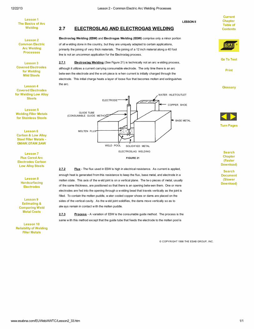
12/22/13 Lesson 2 - Common Electric Arc Welding Processes
www.esabna.com/EUWeb/AWTC/Lesson2_33.htm 1/1
© COPYRIGHT 1998 THE ESAB GROUP, INC.
LESSON II
2.7 ELECTROSLAG AND ELECTROGAS WELDING
Electroslag Welding (ESW) and Electrogas Welding (EGW) comprise only a minor portion
of all w elding done in the country, but they are uniquely adapted to certain applications,
primarily the joining of very thick materials. The joining of a 12 inch material along a 40 foot
line is not an uncommon application for the Electroslag process.
2.7.1 Electroslag Welding (See Figure 21) is technically not an arc w elding process,
although it utilizes a current carrying consumable electrode. The only time there is an arc
betw een the electrode and the w ork piece is w hen current is initially charged through the
electrode. This initial charge heats a layer of loose f lux that becomes molten and extinguishes
the arc.
2.7.2 Flux - The f lux used in ESW is high in electrical resistance. As current is applied,
enough heat is generated from this resistance to keep the f lux, base metal, and electrode in a
molten state. This axis of the w eld joint is on a vertical plane. The tw o pieces of metal, usually
of the same thickness, are positioned so that there is an opening betw een them. One or more
electrodes are fed into the opening through a w elding bead that travels vertically as the joint is
f illed. To contain the molten puddle, w ater cooled copper shoes or dams are placed on the
sides of the vertical cavity. As the w eld joint solidif ies, the dams move vertically so as to
alw ays remain in contact w ith the molten puddle.
2.7.3 Process - A variation of ESW is the consumable guide method. The process is the
same w ith this method except that the guide tube that feeds the electrode to the molten pool is
WATER INLET/OUTLET
COPPER SHOE
BASE METAL
SOLIDIFIED METALWELD POOL
MOLTEN FLUX
GUIDE TUBE(CONSUMABLE GUIDE METHOD)
ELECTRODE
ELECTROSLAG WELDING
FIGURE 21
Current
Chapter Table of
Contents
Lesson 1The Basics of Arc
Welding
Lesson 2Common Electric
Arc Welding
Processes
Lesson 3
Covered Electrodes
for WeldingMild Steels
Go To Test
Lesson 4
Covered Electrodes
for Welding Low AlloySteels
Lesson 5
Welding Filler Metalsfor Stainless Steels
Glossary
Lesson 6
Carbon & Low AlloySteel Filler Metals -GMAW,GTAW,SAW
SearchChapter
(FasterDownload)
Lesson 7
Flux Cored ArcElectrodes CarbonLow Alloy Steels
Turn Pages
Lesson 8Hardsurfacing
Electrodes
SearchDocument
(SlowerDownload)
Lesson 9
Estimating &Comparing Weld
Metal Costs
Lesson 10
Reliability of Welding
Filler Metals
12/22/13 Lesson 2 - Common Electric Arc Welding Processes
www.esabna.com/EUWeb/AWTC/Lesson2_34.htm 1/1
© COPYRIGHT 1998 THE ESAB GROUP, INC.
LESSON II
also consumed. The chief advantage w ith this method is the elimination of the electrode
holder w hich must move vertically w ith the w eld pool. Also since the guide tube is consumed,
the deposition rate is slightly increased w ith this method.
2.7.4 Equipment - The equipment used in ESW is all automatic and of special design.
The pow er source may use either AC or DC current. The electrode may be either solid or f lux
cored, although if the f lux cored is used, it must be specially formulated so as not to contain its
normal amount of slag forming ingredients.
2.7.5 Summary - Electrogas Welding is similar to ESW as far as the mechanical as-
pects are concerned. The equipment is automatic, the w elding head travels vertically, and the
molten puddle is retained by shoes on the sides of the joint. The difference is that Electrogas
Welding utilizes an arc and it is externally gas shielded. The pow er source is also limited to
DC operation. The electrodes used in EGW can be either solid or f lux cored.
Current
Chapter Table of
Contents
Lesson 1The Basics of Arc
Welding
Lesson 2Common Electric
Arc Welding
Processes
Lesson 3
Covered Electrodes
for WeldingMild Steels
Go To Test
Lesson 4
Covered Electrodes
for Welding Low AlloySteels
Lesson 5
Welding Filler Metalsfor Stainless Steels
Glossary
Lesson 6
Carbon & Low AlloySteel Filler Metals -GMAW,GTAW,SAW
SearchChapter
(FasterDownload)
Lesson 7
Flux Cored ArcElectrodes CarbonLow Alloy Steels
Turn Pages
Lesson 8Hardsurfacing
Electrodes
SearchDocument
(SlowerDownload)
Lesson 9
Estimating &Comparing Weld
Metal Costs
Lesson 10
Reliability of Welding
Filler Metals
12/22/13 Lesson 2 - Common Electric Arc Welding Processes
www.esabna.com/EUWeb/AWTC/Lesson2_35.htm 1/1
© COPYRIGHT 1998 THE ESAB GROUP, INC.
LESSON II
APPENDIX A
LESSON II - GLOSSARY OF TERMS
Arc Blow - Deviation of the direction of the w elding arc caused by magnetic f ields in the
w ork piece w hen w elding w ith direct current.
Straight
Polarity- Welding condition w hen the electrode is connected to the negative terminal
and the w ork is connected to the positive terminal of the w elding pow er source.
Reverse
Polarity- Welding condition w hen the electrode is connected to the positive terminal
and the w ork is connected to the negative terminal of the w elding pow er
source.
Slag - The brittle mass that forms over the w eld bead on w elds made w ith coated
electrodes, f lux cored electrodes, submerged arc w elding and other slag
producing w elding processes. Welds made w ith the gas metal arc and the
gas tungsten arc w elding processes are slag free.
Manual Arc
Welding- Welding w ith a coated electrode w here the operator's hand controls travel
speed and the rate the electrode is fed into the arc.
Semi-Automatic
Welding- Welding w ith a continuous solid w ire or f lux cored electrode w here the w ire
feed speed, shielding gas f low rate, and voltage are preset on the equipment,
and the operator guides the hand held w elding gun along the joint to be
w elded.
Slag
Inclusion- A w eld defect w here slag is entrapped in the w eld metal before it can f loat to
the surface.
Root Pass - The initial pass in a multi-pass w eld, usually requiring 100% penetration.
Current
Chapter Table of
Contents
Lesson 1The Basics of Arc
Welding
Lesson 2Common Electric
Arc Welding
Processes
Lesson 3
Covered Electrodes
for WeldingMild Steels
Go To Test
Lesson 4
Covered Electrodes
for Welding Low AlloySteels
Lesson 5
Welding Filler Metalsfor Stainless Steels
Glossary
Lesson 6
Carbon & Low AlloySteel Filler Metals -GMAW,GTAW,SAW
SearchChapter
(FasterDownload)
Lesson 7
Flux Cored ArcElectrodes CarbonLow Alloy Steels
Turn Pages
Lesson 8Hardsurfacing
Electrodes
SearchDocument
(SlowerDownload)
Lesson 9
Estimating &Comparing Weld
Metal Costs
Lesson 10
Reliability of Welding
Filler Metals
12/22/13 Lesson 2 - Common Electric Arc Welding Processes
www.esabna.com/EUWeb/AWTC/Lesson2_36.htm 1/1
© COPYRIGHT 1998 THE ESAB GROUP, INC.
LESSON II
Gas Ions - Shielding gas atoms that, in the presence of an electrical current, lose one or
more electrons and therefore, carry a positive electrical charge. The provide
a more electrically conductive path for the arc betw een the electrode and the
w ork piece.
High
Frequency - (as applied to gas-tungsten arc w elding)
An alternating current consisting of over 50,000 cycles per second at high
voltage, low amperage that is superimposed on the w elding circuit in GTAW
pow er sources. It ionizes a path for non-touch arc starting and stabilizes the
arc w hen w elding w ith alternating current.
Inert Gases - Gases that are chemically inactive. They do not readily combine w ith other
elements.
Flux - In arc w elding, f luxes are formulations that, w hen subjected to the arc, act as
a cleaning agent by dissolving oxides, releasing trapped gases and slag and
generally cleaning the w eld metal by f loating the impurities to the surface
w here they solidify in the slag covering. The f lux also serves to reduce spatter
and contributes to w eld bead shape. The f lux may be the coating on the
electrode, inside the electrode as in f lux cored types, or in a granular form as
used in submerged arc w elding.
Current
Density - The amperes per square inch of cross-sectional area of an electrode. High
current density results in high electrode melt-off rate and a concentrated, deep
penetrating arc.
Slope or Slope
Control - A necessary feature in w elding pow er sources used for short circuiting arc
w elding. Slope Control reduces the short circuiting current each time the
electrode touches the w eld puddle (See Section 2.5.3).
Inductance - (as applies to short circuiting arc w elding)
A feature in w elding pow er sources designed for short circuiting arc w elding
to retard the rate of current rise each time the electrode touches the w eld
puddle.
Current
Chapter Table of
Contents
Lesson 1The Basics of Arc
Welding
Lesson 2Common Electric
Arc Welding
Processes
Lesson 3
Covered Electrodes
for WeldingMild Steels
Go To Test
Lesson 4
Covered Electrodes
for Welding Low AlloySteels
Lesson 5
Welding Filler Metalsfor Stainless Steels
Glossary
Lesson 6
Carbon & Low AlloySteel Filler Metals -GMAW,GTAW,SAW
SearchChapter
(FasterDownload)
Lesson 7
Flux Cored ArcElectrodes CarbonLow Alloy Steels
Turn Pages
Lesson 8Hardsurfacing
Electrodes
SearchDocument
(SlowerDownload)
Lesson 9
Estimating &Comparing Weld
Metal Costs
Lesson 10
Reliability of Welding
Filler Metals

12/22/13 Lesson 2 - Common Electric Arc Welding Processes
www.esabna.com/EUWeb/AWTC/Lesson2_37.htm 1/1
© COPYRIGHT 1998 THE ESAB GROUP, INC.
LESSON II
Contact Tip - That part of a gas metal arc w elding gun or f lux cored arc w elding gun that
transfers the w elding current to the w elding w ire immediately before the w ire
enters the arc.
Spray
Transfer
- Mode of metal transfer across the arc w here the molten metal droplets are
smaller than the electrode diameter and are axially directed to the w eld puddle.
Requires high voltage and amperage settings and a shielding gas of at least
80% argon.
Globular
Transfer
- Mode of metal transfer across the arc w here a molten ball larger than the
electrode diameter forms at the tip of the electrode. On detachment, it takes
on an irregular shape and tumbles tow ards the w eld puddle sometimes
shorting betw een the electrode and w ork at irregular intervals. Occurs w hen
using shielding gases other than those consisting of at least 80% argon and
at medium current settings.
Pulse
Transfer
- Mode of metal transfer somew hat betw een spray and short circuiting. The
specif ic pow er source has built into it tw o output levels: a steady background
level, and a high output (peak) level. The later permits the transfer of metal
across the arc. This peak output is controllable betw een high and low values
up to several hundred cycles per second. The result of such a peak output
produces a spray arc below the typical transition current.
Short-circuiting
Transfer
- Mode of metal transfer in gas metal arc w elding at low voltage and amperage.
Transfer takes place each time the electrode touches or short-circuits to the
w eld puddle, extinguishing the arc. The short-circuiting current causes the
electrode to neck dow n, melt off, and then repeats the cycle.
Trimix or
Triple Mix
- A shielding gas consisting of approximately 90% helium, 7-1/2% argon, and
2-1/2% carbon dioxide used primarily for short-circuiting arc w elding of
stainless steels. Maintains corrosion resistance of the stainless steel and
produces good w etting and excellent w eld bead shape.
Current
Chapter Table of
Contents
Lesson 1The Basics of Arc
Welding
Lesson 2Common Electric
Arc Welding
Processes
Lesson 3
Covered Electrodes
for WeldingMild Steels
Go To Test
Lesson 4
Covered Electrodes
for Welding Low AlloySteels
Lesson 5
Welding Filler Metalsfor Stainless Steels
Glossary
Lesson 6
Carbon & Low AlloySteel Filler Metals -GMAW,GTAW,SAW
SearchChapter
(FasterDownload)
Lesson 7
Flux Cored ArcElectrodes CarbonLow Alloy Steels
Turn Pages
Lesson 8Hardsurfacing
Electrodes
SearchDocument
(SlowerDownload)
Lesson 9
Estimating &Comparing Weld
Metal Costs
Lesson 10
Reliability of Welding
Filler Metals

12/22/13 Lesson 2 - Common Electric Arc Welding Processes
www.esabna.com/EUWeb/AWTC/Lesson2_38.htm 1/1
© COPYRIGHT 1998 THE ESAB GROUP, INC.
LESSON II
Electrical
Stick-Out
- In any w elding process using a solid or f lux cored w ire, the electrical stick-out
is the distance from the contact tip to the unmelted electrode end. Sometimes
called the "amount of w ire in resistance". This distance influences melt-off
rate, penetration, and w eld bead shape.
Out-of-Position
Welds
- Welds made in positions other than f lat or horizontal f illets.
Weld
Positions
-
FLAT HORIZONTAL FILLET
VERTICAL OVERHEAD
HORIZONTALBUTT
POSITIONED FILLET(FLAT)
Current
Chapter Table of
Contents
Lesson 1The Basics of Arc
Welding
Lesson 2Common Electric
Arc Welding
Processes
Lesson 3
Covered Electrodes
for WeldingMild Steels
Go To Test
Lesson 4
Covered Electrodes
for Welding Low AlloySteels
Lesson 5
Welding Filler Metalsfor Stainless Steels
Glossary
Lesson 6
Carbon & Low AlloySteel Filler Metals -GMAW,GTAW,SAW
SearchChapter
(FasterDownload)
Lesson 7
Flux Cored ArcElectrodes CarbonLow Alloy Steels
Turn Pages
Lesson 8Hardsurfacing
Electrodes
SearchDocument
(SlowerDownload)
Lesson 9
Estimating &Comparing Weld
Metal Costs
Lesson 10
Reliability of Welding
Filler Metals