
Welding Automation and Robotics -...
8
OBJECTIVES After completing this chapter, the student should be able to: • Describe the manual, semiautomatic, machine, automatic, and automated joining processes. • Explain the role that the welder plays in the operation of the manual, semiautomatic, machine, automatic, and automated joining processes. • Give examples of the types of applications the manual, semiautomatic, machine, automatic, and automated joining processes are used for. KEY TERMS Chapter 25 Welding Automation and Robotics automated joining automatic joining cycle time industrial robot machine joining manipulator manual joining pick-and-place robot semiautomatic joining sensors INTRODUCTION The first industrial robots were pick-and-place robots that were used to move material with little repetitive accuracy required. Today, computers have improved the accuracy, reliability, and functionality so that robots now serve as intelligent controllers for automation. The decreasing cost and advance- ments have made this technology possible, even for small businesses. Automation has allowed manufacturers to increase productivity and cut costs, which makes their products more competitively priced. This chapter gives you a general overview of automatic welding processes and robotics. 597 Copyright 2012 Cengage Learning. All Rights Reserved. May not be copied, scanned, or duplicated, in whole or in part. Due to electronic rights, some third party content may be suppressed from the eBook and/or eChapter(s). Editorial review has deemed that any suppressed content does not materially affect the overall learning experience. Cengage Learning reserves the right to remove additional content at any time if subsequent rights restrictions require it.
-
Upload
phungthien -
Category
Documents
-
view
214 -
download
1
Transcript of Welding Automation and Robotics -...

OBJECTIVESAfter completing this chapter, the student should be able to:
• Describe the manual, semiautomatic, machine, automatic, and automated joining processes.
• Explain the role that the welder plays in the operation of the manual, semiautomatic, machine, automatic, and automated joining processes.
• Give examples of the types of applications the manual, semiautomatic, machine, automatic, and automated joining processes are used for.
KEY TERMS
Chapter 25Welding Automation and Robotics
automated joining
automatic joining
cycle time
industrial robot
machine joining
manipulator
manual joining
pick-and-place robot
semiautomatic joining
sensors
INTRODUCTIONThe first industrial robots were pick-and-place robots that were used to move material with little repetitive accuracy required. Today, computers have improved the accuracy, reliability, and functionality so that robots now serve as intelligent controllers for automation. The decreasing cost and advance-ments have made this technology possible, even for small businesses.
Automation has allowed manufacturers to increase productivity and cut costs, which makes their products more competitively priced.
This chapter gives you a general overview of automatic welding processes and robotics.
597
Copyright 2012 Cengage Learning. All Rights Reserved. May not be copied, scanned, or duplicated, in whole or in part. Due to electronic rights, some third party content may be suppressed from the eBook and/or eChapter(s). Editorial review has deemed that any suppressed content does not materially affect the overall learning experience. Cengage Learning reserves the right to remove additional content at any time if subsequent rights restrictions require it.

598 CHAPTER 25
Manual Joining Processes A manual joining process is one that is completely performed by hand. You control all of the manipula-tion, rate of travel, joint tracking, and, in some cases, the rate at which filler metal is added to the weld. The manipulation of the electrode or torch in a straight line or oscillating pattern affects the size and shape of the weld, Figure 25-1. The manipulation pattern may also be used to control the size of the weld pool during out-of-position welding. The rate of travel or speed at which the weld progresses along the joint affects the width, reinforcement, and penetration of the weld, Figure 25-2. The placement or location of the weld bead within the weld joint affects the strength, appearance, and possible acceptance of the joint. The rate at which filler metal is added to the weld affects the reinforcement, width, and appearance of the weld, Figure 25-3.
The most commonly used manual arc (MA) weld-ing process is shielded metal arc welding (SMAW). The flexibility you have in performing the weld makes this process one of the most versatile. By changing the manipulation, rate of travel, or joint tracking, you can make an acceptable weld on a variety of material thicknesses, Figure 25-4.
The most commonly used manual arc welding, gas welding, and brazing processes are listed in Table 25-1.
Semiautomatic Joining Processes A semiautomatic joining process is one in which the filler metal is fed into the weld automatically. You con-trol most other functions. The addition of filler metal to the weld by an automatic wire-feeder system enables you to increase the uniformity of welds, productivity,
SIDE TO SIDE BACK STEPSTRAIGHT
FIGURE 25-1 The electrode manipulation affects the size and shape of the weld bead. © Cengage Learning 2012
WIDTH
PENETRATION
REINFORCEMENT
FIGURE 25-2 The travel rate of the weld affects width, reinforcement, and penetration of the weld bead.© Cengage Learning 2012
WELD REINFORCEMENT FROMADDITIONAL FILLER METAL
FIGURE 25-3 Addition of filler metal. © Cengage Learning 2012
OFF-CENTER, FAST TRAVELSLOW, WEAVE TRAVELFAST, STRAIGHT TRAVEL
FIGURE 25-4 Controlling weld bead size by adjusting welding parameters. © Cengage Learning 2012
ArcShielded metal arc welding (SMAW)Gas tungsten arc welding (GTAW)
GasOxyacetylene welding (OAW)
BrazingTorch brazing (TB)
Table 25-1 Manual Joining Processes
Copyright 2012 Cengage Learning. All Rights Reserved. May not be copied, scanned, or duplicated, in whole or in part. Due to electronic rights, some third party content may be suppressed from the eBook and/or eChapter(s). Editorial review has deemed that any suppressed content does not materially affect the overall learning experience. Cengage Learning reserves the right to remove additional content at any time if subsequent rights restrictions require it.
Welding Automation and Robotics 599
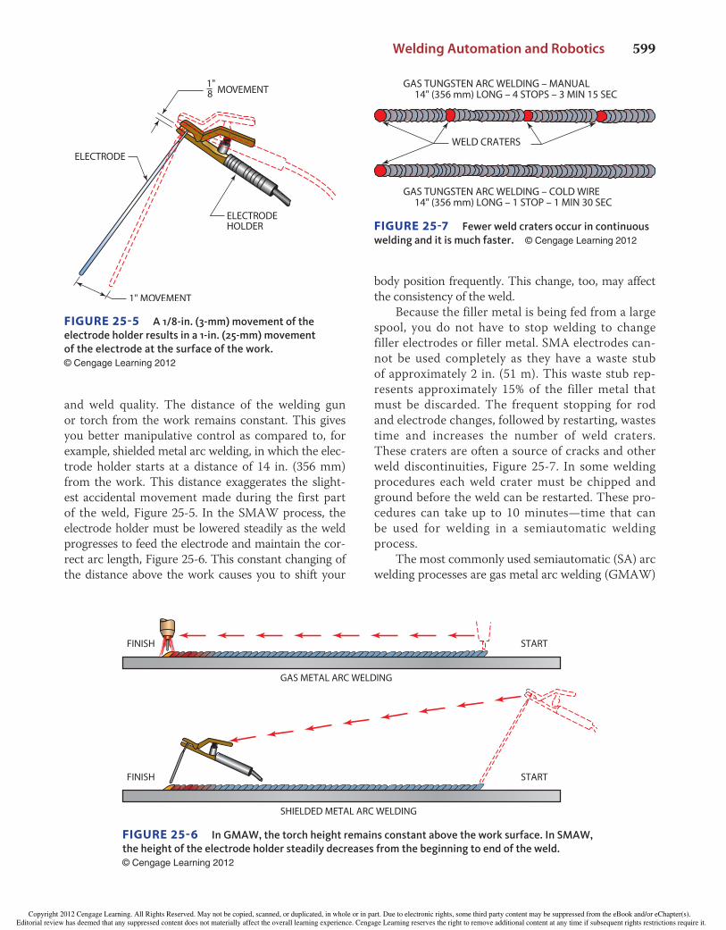
and weld quality. The distance of the welding gun or torch from the work remains constant. This gives you better manipulative control as compared to, for example, shielded metal arc welding, in which the elec-trode holder starts at a distance of 14 in. (356 mm) from the work. This distance exaggerates the slight-est accidental movement made during the first part of the weld, Figure 25-5. In the SMAW process, the electrode holder must be lowered steadily as the weld progresses to feed the electrode and maintain the cor-rect arc length, Figure 25-6. This constant changing of the distance above the work causes you to shift your
body position frequently. This change, too, may affect the consistency of the weld.
Because the filler metal is being fed from a large spool, you do not have to stop welding to change filler electrodes or filler metal. SMA electrodes can-not be used completely as they have a waste stub of approximately 2 in. (51 m). This waste stub rep-resents approximately 15% of the filler metal that must be discarded. The frequent stopping for rod and electrode changes, followed by restarting, wastes time and increases the number of weld craters. These craters are often a source of cracks and other weld discontinuities, Figure 25-7. In some welding procedures each weld crater must be chipped and ground before the weld can be restarted. These pro-cedures can take up to 10 minutes—time that can be used for welding in a semiautomatic welding process.
The most commonly used semiautomatic (SA) arc welding processes are gas metal arc welding (GMAW)
1"8 MOVEMENT
ELECTRODE
ELECTRODEHOLDER
1" MOVEMENT
FIGURE 25-5 A 1/8-in. (3-mm) movement of the electrode holder results in a 1-in. (25-mm) movement of the electrode at the surface of the work. © Cengage Learning 2012
FINISH START
GAS METAL ARC WELDING
FINISH START
SHIELDED METAL ARC WELDING
FIGURE 25-6 In GMAW, the torch height remains constant above the work surface. In SMAW, the height of the electrode holder steadily decreases from the beginning to end of the weld. © Cengage Learning 2012
GAS TUNGSTEN ARC WELDING – MANUAL 14" (356 mm) LONG – 4 STOPS – 3 MIN 15 SEC
GAS TUNGSTEN ARC WELDING – COLD WIRE 14" (356 mm) LONG – 1 STOP – 1 MIN 30 SEC
WELD CRATERS
FIGURE 25-7 Fewer weld craters occur in continuous welding and it is much faster. © Cengage Learning 2012
Copyright 2012 Cengage Learning. All Rights Reserved. May not be copied, scanned, or duplicated, in whole or in part. Due to electronic rights, some third party content may be suppressed from the eBook and/or eChapter(s). Editorial review has deemed that any suppressed content does not materially affect the overall learning experience. Cengage Learning reserves the right to remove additional content at any time if subsequent rights restrictions require it.

600 CHAPTER 25
and flux cored arc welding (FCAW). Table 25-2 lists several other semiautomatic processes.
Machine Joining Processes A machine joining process is one in which the weld-ing is performed by equipment and you control the welding progress by making adjustments as required. The parts being joined may or may not be loaded and unloaded automatically. You may monitor the join-ing progress by watching it directly, observing instru-ments only, or using a combination of both methods. Adjustments in travel speed, joint tracking, work-to-gun or work-to-torch distance, and current set-tings may be needed to ensure that the joint is made according to specifications.
The work may move past a stationary welding or joining station, Figure 25-8, or it may be held sta-tionary and the welding machine moves on a beam or track along the joint, Figure 25-9. On some large machine welds, the operator may ride with the welding head along the path of the weld. During the assembly of the external fuel tanks used for the space shuttle, two operators were required for a few of the machine welds. One operator watched the root side of the weld while the other observed the face side of the weld. They were able to communicate with each other so that any needed changes could be made.
To minimize adjustments during machine welds, a test weld is often performed just before the actual weld is produced. This practice weld helps increase the already high reliability of machine welds.
Automatic Joining ProcessesAn automatic joining process is a dedicated process (designed to do only one type of welding on a specific part) that does not require you to make adjustments during the actual welding cycle. All operating guide-lines are preset, and you may or may not have to load or unload parts. Automatic equipment is often dedicated
to one type of product or part. A large investment is usually required in jigs and fixtures used to hold the parts to be joined in the proper alignment. The oper-ational cycle is computer controlled. The cycle may be as simple as starting and stopping points, or it may be more complex. A more complex cycle may include such steps as prepurge time, hot start, initial current, pulse power, downslope, final current, and postpurge time, Figure 25-10.
Automatic welding or brazing is best suited to large-volume production runs because of the expense involved in special jigs and fixtures.
Automated Joining Automated joining processes are similar to auto-matic joining except that they are flexible and more easily adjusted or changed. Unlike automatic joining, there is no dedicated machine for each product. The equipment can be easily adapted or changed to pro-duce a wide variety of high-quality welds.
The industrial robot is rapidly becoming the main component in automated welding or joining stations. The welding or joining cycles are controlled by com-puters or microprocessors. The flexibility provided by automated workstations makes it possible for even small companies with limited production runs to invest in automated equipment. The equipment is controlled by programs, or a series of machine com-mands expressed in numerical codes, that direct the welding, cutting, assembling, or any other activities. The programs can be stored and quickly changed. Some systems can store and retrieve many different programs internally. Other systems are controlled by a host computer. Both types of systems can speed up production when frequent changes are required.
Industrial Robots An industrial robot is a “reprogrammable, multi-functional manipulator designed to move material, parts, tools, or specialized devices through variable programmed motions for the performance of a vari-ety of tasks.”∗ Industrial robots are primarily powered by electric stepping motors, hydraulics, or pneumat-ics and are controlled by a program, Figure 25-11.
Robots can be used to perform a variety of indus-trial functions, including grinding, painting, assembling,
Welding Processes
Gas metal arc welding (GMAW)
Flux cored arc welding (FCAW)
Submerged arc welding (SAW)
Gas tungsten arc welding (GTAW)
Cold-hot wire feed
Table 25-2 Semiautomatic Joining Processes
∗Robot Institute of America.
Copyright 2012 Cengage Learning. All Rights Reserved. May not be copied, scanned, or duplicated, in whole or in part. Due to electronic rights, some third party content may be suppressed from the eBook and/or eChapter(s). Editorial review has deemed that any suppressed content does not materially affect the overall learning experience. Cengage Learning reserves the right to remove additional content at any time if subsequent rights restrictions require it.

Welding Automation and Robotics 601
machining, inspecting, flame cutting, product han-dling, and welding.
Robots range in size and complexity from small desktop units capable of lifting only a few ounces to large floor models capable of lifting tons. Most robots can perform movements in three basic directions: longitudinal (X), transverse (Y), and vertical (Z),
Figure 25-12. The tool end of the robot arm may also be jointed so that it can tilt and rotate, Figure 25-13.
The robot may be used with other components to increase production and the flexibility of the system. A computer or microprocessor can synchronize the robot’s operation to petitioners, conveyors, automatic fixtures, and other production machines. Parallel or
MOTORIZED50-M SPINDLE
16"THETA TORCH SLIDE
“S” TORCH STAND
TAILSTOCK
X-Y-Z TORCH SLIDES
1" THRU HOLE
20"
CROSS SLIDE
10"
17.5"
WELDING TORCH (BY CUSTOMER)
34"
5"
42.5"(A)
(B)
FIGURE 25-8 Two precision bench-welding systems. (A) Larry Jeffus; (B) ARC Machines, Inc.
Copyright 2012 Cengage Learning. All Rights Reserved. May not be copied, scanned, or duplicated, in whole or in part. Due to electronic rights, some third party content may be suppressed from the eBook and/or eChapter(s). Editorial review has deemed that any suppressed content does not materially affect the overall learning experience. Cengage Learning reserves the right to remove additional content at any time if subsequent rights restrictions require it.

602 CHAPTER 25
FIGURE 25-9 Automatic GTA machine welding along the seam of a stationary pipe. The Lincoln Electric Company
HIGH PULSE TIME
UPSLOPE
INITIAL CURRENT
PREFLOW TIME
FINALCURRENT
POSTFLOW TIME
WELDING CYCLE TIMESTART STOP
CU
RREN
T SE
TTIN
G
HOTSTART LOW PULSE TIME
DOWNSLOPE
FIGURE 25-10 Typical GTAW automatic welding program. © Cengage Learning 2012
FIGURE 25-11 Robot control unit. The Lincoln Electric Company
FIGURE 25-12 Machine axis. Reproduced with permis-sion from FANUC Robotics America Corporation © FANUC Robotics America Corporation. All rights reserved.
Copyright 2012 Cengage Learning. All Rights Reserved. May not be copied, scanned, or duplicated, in whole or in part. Due to electronic rights, some third party content may be suppressed from the eBook and/or eChapter(s). Editorial review has deemed that any suppressed content does not materially affect the overall learning experience. Cengage Learning reserves the right to remove additional content at any time if subsequent rights restrictions require it.

Welding Automation and Robotics 603
multiple workstations increase the duty cycle (the fraction of time during which welding or work is being done) and reduce cycle time (the period of time from starting one operation to starting another), Figure 25-14. Parts can be loaded or unloaded by the operator at one station while the robot welds at another station.
SafetyThe following precautions are recommended for the use of automatic welding equipment and robots:
All personnel should be instructed in the safe oper- •ation of the robot. All personnel should be instructed in the location •of an emergency power shutoff. The work area should be restricted to authorized •persons only. The work area should have fences, gates, or other •restrictions to prevent access by unauthorized personnel.
Sensors • should be mounted around the floor and work area to stop all movement when unauthorized personnel are detected in the work area during the operation. The arc welding light should be screened from •other work areas. A breakaway toolholder should be used in case of •accidental collision with the part, Figure 25-15.A signal should sound or flash before the robot •starts moving.
TILT ROTATION
SWING
(A)
(B)
FIGURE 25-13 The tool end may be jointed so that it can tilt and rotate. Larry Jeffus
FIGURE 25-14 Rotating worktable increases the work zone. Eutectic Corporation
FIGURE 25-15 When using automatic equipment and robots, a break away collision sensor should be used. Applied Robotics, Inc.
Copyright 2012 Cengage Learning. All Rights Reserved. May not be copied, scanned, or duplicated, in whole or in part. Due to electronic rights, some third party content may be suppressed from the eBook and/or eChapter(s). Editorial review has deemed that any suppressed content does not materially affect the overall learning experience. Cengage Learning reserves the right to remove additional content at any time if subsequent rights restrictions require it.

604 CHAPTER 25
SUMMARY
The automation of welding does not necessarily have to be in large shops. You may find that in some pro-duction applications it would be beneficial to use turntables or positioners. These can either fully or partially automate the welding process so that welder fatigue will be reduced. As you reduce welder fatigue with simple automation equipment, you can increase productivity significantly. It is important, there-fore, not to look at automation as a major undertak-ing in every case. Many welding applications can be improved by using automated equipment, thereby
reducing welder fatigue, increasing productivity, and reducing weld defects.
As the number of companies using automated and robotic equipment has increased, the cost of equip-ment has significantly decreased, and the versatil-ity of the equipment has improved. Some equipment companies provide you with test runs of your prod-uct to help you determine the appropriateness of their equipment for your application. Such sample welds will help you determine which equipment is the most cost effective and appropriate for your application.
REVIEW QUESTIONS
Describe a manual joining process.1. What is the most commonly used manual arc 2. welding process?What is a semiautomatic joining process?3. Compare the distance of the welding gun or torch 4. from the work in the semiautomatic joining pro-cess compared to the SMAW process. What are the advantages of using filler metal that is 5. fed from a large spool rather than filler electrodes?What are the most commonly used semiauto-6. matic arc welding processes?Describe a machine joining process.7. What type of adjustments to the equipment 8. might be needed in a machine joining process?
Describe an automatic joining process.9. Why is automatic welding or brazing best suited 10. to large-volume production runs?How are11. automated joining processes different from automatic joining?What are automated joining processes con-12. trolled by?What functions can industrial robots perform?13. What three basic directions can most robots per-14. form movements in?What is a duty cycle?15. Discuss several safety precautions that should be 16. followed when using automatic welding equip-ment and robots.
Copyright 2012 Cengage Learning. All Rights Reserved. May not be copied, scanned, or duplicated, in whole or in part. Due to electronic rights, some third party content may be suppressed from the eBook and/or eChapter(s). Editorial review has deemed that any suppressed content does not materially affect the overall learning experience. Cengage Learning reserves the right to remove additional content at any time if subsequent rights restrictions require it.


