Welcome This is a document to explains the chosen concept to the animator. This will take you...
22
Welcome This is a document to explains the chosen concept to the animator. This will take you through a 5 section process to provide the necessary details to the animator before starting the animation. The legend on the left will indicate the current status of the document. The big Black coloured number will denote the current section, the Grey color would denote the completed sections, and the Turquoise color would denote the remaining sections. The slides having yellow background (like this one) are the 'Instruction slides' 5 2 1 4 3
-
Upload
karli-pittmon -
Category
Documents
-
view
219 -
download
0
Transcript of Welcome This is a document to explains the chosen concept to the animator. This will take you...
WelcomeThis is a document to explains the chosen concept to the
animator.
This will take you through a 5 section process to provide
the necessary details to the animator before starting the
animation.
The legend on the left will indicate the current status of
the document. The big Black coloured number will denote
the current section, the Grey color would denote the
completed sections, and the Turquoise color would
denote the remaining sections.
The slides having yellow background (like this one) are the
'Instruction slides'5
2
1
4
3
Shell and Tube Heat
ExchangerThe animation explains the working of the Shell &Tube Heat Exchanger
and highlights the effect of various process parameters on the performance
Course Name: (Optional)
Author/sNitin V. Bhate
Learning objectives
After interacting with this Learning Object, the learner will be able to:
Get a sound understanding of the concept and working of shell & tube heat exchanger
Realize the significance of baffles
Visualize flow patterns on the tube and the shell side
Appreciate the effect of various process parameters on the rate of heat transfer
5
3
2
4
1
Master layout or diagram • Make a schematic diagram of the concept
• Explain the animator about the beginning and ending of the process.
• Draw image big enough for explaining.
• In the image, identify and label different components of the process/phenomenon. (These are like characters in a film)
• Illustrate the basic flow of action by using arrows. Use BOLD lines in the diagram (minimum 2pts.)
• In the slide after that, provide the definitions of ALL the labels used in the diagram
• You may have multiple master layouts.
• In this case, number the master layout. (e.g. Master layout 1, 2, 3…)
5
3
2
4
1

Master Layout
5
3
2
4
1Baffle
Tie rod
Process fluid Heating/Cooling fluidTubes
Shell
Tube side outlet nozzle
Tube side inlet nozzle
Shell side inlet nozzle
Shell side outlet nozzle
TubeChannel
TubeChannel
Tube sheet
Tube sheet
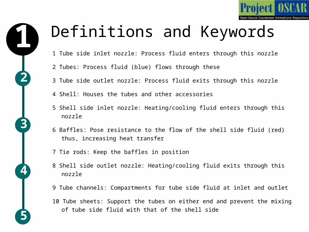
Definitions and Keywords1 Tube side inlet nozzle: Process fluid enters through this nozzle
2 Tubes: Process fluid (blue) flows through these
3 Tube side outlet nozzle: Process fluid exits through this nozzle
4 Shell: Houses the tubes and other accessories
5 Shell side inlet nozzle: Heating/cooling fluid enters through this nozzle
6 Baffles: Pose resistance to the flow of the shell side fluid (red) thus,
increasing heat transfer
7 Tie rods: Keep the baffles in position
8 Shell side outlet nozzle: Heating/cooling fluid exits through this nozzle
9 Tube channels: Compartments for tube side fluid at inlet and outlet
10 Tube sheets: Support the tubes on either end and prevent the mixing of
tube side fluid with that of the shell side
5
3
2
4
1
Explain the processIn this step, use an example to explain the
concept. It can be an analogy, a scenario, or an action which explains this concept/process/topic
Try to use examples from day-to-day life to make it more clear
You have to describe what steps the animator should take to make your concept come alive as a series of moving images.
Keep the examples simple to understand, and also to illustrate/animate.
5
3
1
4
2
Analogy / Scenario / Action
5
3
1
4
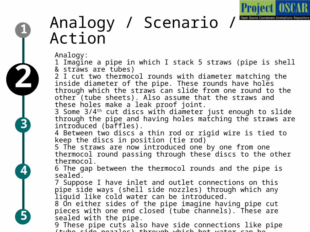
2Analogy: 1 Imagine a pipe in which I stack 5 straws (pipe is shell & straws are tubes)2 I cut two thermocol rounds with diameter matching the inside diameter of the pipe. These rounds have holes through which the straws can slide from one round to the other (tube sheets). Also assume that the straws and these holes make a leak proof joint.3 Some 3/4th cut discs with diameter just enough to slide through the pipe and having holes matching the straws are introduced (baffles).4 Between two discs a thin rod or rigid wire is tied to keep the discs in position (tie rod)5 The straws are now introduced one by one from one thermocol round passing through these discs to the other thermocol.6 The gap between the thermocol rounds and the pipe is sealed.7 Suppose I have inlet and outlet connections on this pipe side ways (shell side nozzles) through which any liquid like cold water can be introduced.8 On either sides of the pipe imagine having pipe cut pieces with one end closed (tube channels). These are sealed with the pipe.9 These pipe cuts also have side connections like pipe (tube side nozzles) through which hot water can be introduced.10 If both hot and cold waters are circulated through the straw side and the pipe side, the hot fluid coming out of the other side of the straw end will be cooler and vice versa.11 This is visualizing a shell & tube heat exchanger
Stepwise description of processThe goal of the document is to provide instructions to an
animator who is not a expert.
You have to describe what steps the animator should take to make your concept come alive as a moving visualization.
Use one slide per step. This will ensure clarity of the explanation.
Add a image of the step in the box, and the details in the table below the box.
You can use any images for reference, but mention about it's copyright status
The animator will have to re-draw / re-create the drawings
Add more slides as per the requirement of the animation5
2
1
4
3

Step 1:
Audio Narration (if any)
Text to be displayed (if any)(DT)
Description of the action/
interactivity
T1: Title of the step, to appear as heading of the screen (if any)
5
2
1
4
3 Process fluid Heating/Cooling fluid
Blue liquid introduced through the entry as shown. It should fill the entire channel
Process fluid at the inlet
5
2
1
4
3
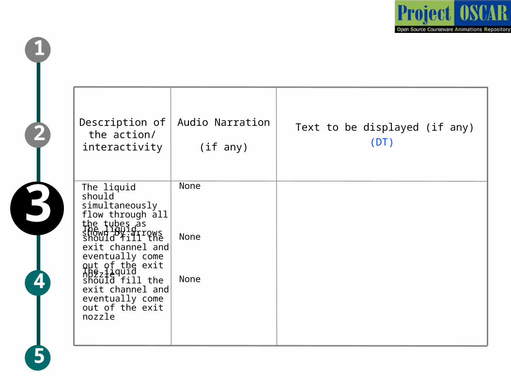
Audio Narration (if any)
Text to be displayed (if any)(DT)
Description of the action/
interactivity
The liquid should simultaneously flow through all the tubes as shown by arrows
None
The liquid should fill the exit channel and eventually come out of the exit nozzle
None
The liquid should fill the exit channel and eventually come out of the exit nozzle
None
5
2
1
4
3
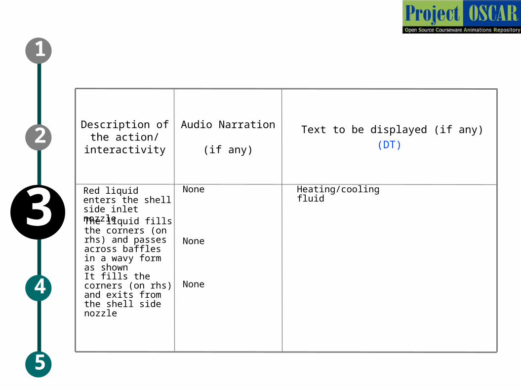
Audio Narration (if any)
Text to be displayed (if any)(DT)
Description of the action/
interactivity
Red liquid enters the shell side inlet nozzle
None
The liquid fills the corners (on rhs) and passes across baffles in a wavy form as shown
None
It fills the corners (on rhs) and exits from the shell side nozzle
None
Heating/cooling fluid
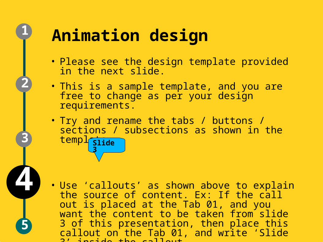
Animation design• Please see the design template provided in the
next slide.
• This is a sample template, and you are free to change as per your design requirements.
• Try and rename the tabs / buttons / sections / subsections as shown in the template.
• Use ‘callouts’ as shown above to explain the source of content. Ex: If the call out is placed at the Tab 01, and you want the content to be taken from slide 3 of this presentation, then place this callout on the Tab 01, and write ‘Slide 3’ inside the callout.
Slide 3
5
2
1
3
4
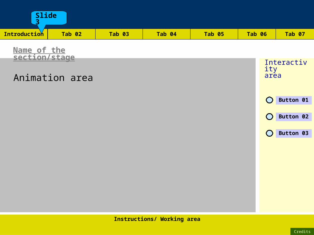
Animation area
Instructions/ Working area
Credits
Name of the section/stage
Interactivityarea
Tab 02 Tab 03 Tab 04 Tab 05 Tab 06 Tab 07
Button 01
Button 02
Button 03
Introduction
Slide 3
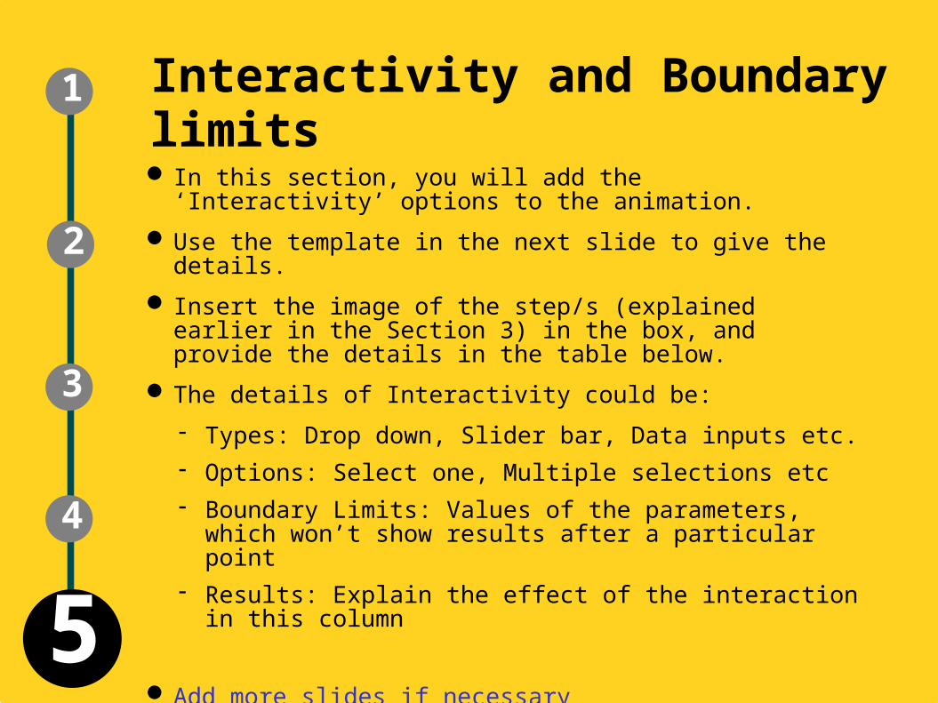
Interactivity and Boundary limits In this section, you will add the ‘Interactivity’ options to
the animation.
Use the template in the next slide to give the details.
Insert the image of the step/s (explained earlier in the Section 3) in the box, and provide the details in the table below.
The details of Interactivity could be:
Types: Drop down, Slider bar, Data inputs etc. Options: Select one, Multiple selections etc Boundary Limits: Values of the parameters, which
won’t show results after a particular point Results: Explain the effect of the interaction in this
column
Add more slides if necessary
4
2
1
3
5
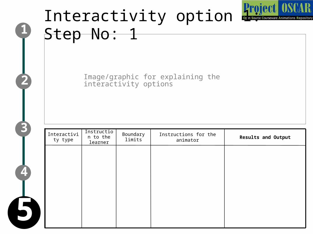
Instructions for the animatorInstruction
to the learner
Results and OutputBoundary
limitsInteractivity
type
Interactivity option 1: Step No: 1
Image/graphic for explaining the interactivity options
4
2
1
3
5
Self- Assessment Questionnaire for Learners
• Please provide a set of questions that a user can answer
based on the LO. They can be of the following types:
– These questions should be 5 in number and can be of
objective type (like MCQ, Match the columns, Yes or
No, Sequencing, Odd One Out).
– The questions can also be open-ended. The user would
be asked to think about the question. The author is
requested to provide hints if possible, but a full answer
is not necessary.
– One can include questions, for which the user will need
to interact with the LO (with certain parameters) in
order to answer it.
– It is better to avoid questions based purely on recall.
APPENDIX 1
Questionnaire:
Use appropriate formatting for the questions
APPENDIX 1

Links for further reading
In the next slide, provide some reference reading material for the users.
It could be books, reference publications, or website URLs.
APPENDIX 2
Links for further reading
Reference websites:
Books:
Research papers:
APPENDIX 2
Summary
• Please provide points to remember to
understand the concept/ key terms of the
animation, in the next slide.
• The summary will help the user in the quick
review of the concept.
APPENDIX 3
Summary
APPENDIX 3