Welch Allyn Pediatric/Infant Scale · PDF fileWelch Allyn Pediatric/Infant Scale Service...
36
Welch Allyn Pediatric/Infant Scale Service Manual Model 4802D – Pediatric/Infant Scale
Transcript of Welch Allyn Pediatric/Infant Scale · PDF fileWelch Allyn Pediatric/Infant Scale Service...

Welch Allyn Pediatric/Infant Scale
Service Manual Model 4802D – Pediatric/Infant Scale
© 2016 Welch Allyn. All rights are reserved. To support the intended use of the product described in this publication, the purchaser of the product is permitted to copy this publication, for internal distribution only, from the media provided by Welch Allyn. No other use, reproduction, or distribution of this publication, or any part of it, is permitted without written permission from Welch Allyn. Welch Allyn assumes no responsibility for any injury to anyone, or for any illegal or improper use of the product, that may result from failure to use this product in accordance with the instructions, cautions, warnings, or statement of intended use published in this manual. Software in this product is Copyright 2016 Welch Allyn or its vendors. All rights are reserved. The software is protected by United States of America copyright laws and international treaty provisions applicable worldwide. Under such laws, the licensee is entitled to use the copy of the software incorporated with this instrument as intended in the operation of the product in which it is embedded. The software may not be copied, decompiled, reverse-engineered, disassembled, or otherwise reduced to human-perceivable form. This is not a sale of the software or any copy of the software; all right, title, and ownership of the software remain with Welch Allyn or its vendors. For information about any Welch Allyn product, contact your local Welch Allyn representative: http://www.welchallyn.com/en/other/contact-us.html
DIR 80021650 Ver. B Revision date: 2017-03
Welch Allyn, Inc. 4341 State Street Road Skaneateles Falls, NY 13153 USA www.welchallyn.com
Customer Support Placing orders, checking on pricing, billing, or repairs
1.800.535.6663, Option 2, 1, 5
9am - 5pm EST
Mon - Fri
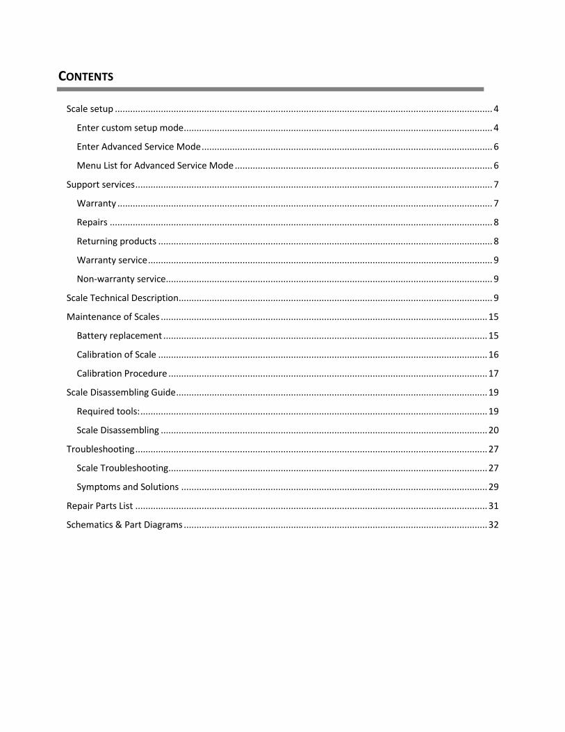
CONTENTS
Scale setup .................................................................................................................................................... 4
Enter custom setup mode ......................................................................................................................... 4
Enter Advanced Service Mode .................................................................................................................. 6
Menu List for Advanced Service Mode ..................................................................................................... 6
Support services ............................................................................................................................................ 7
Warranty ................................................................................................................................................... 7
Repairs ...................................................................................................................................................... 8
Returning products ................................................................................................................................... 8
Warranty service ....................................................................................................................................... 9
Non-warranty service ................................................................................................................................ 9
Scale Technical Description ........................................................................................................................... 9
Maintenance of Scales ................................................................................................................................ 15
Battery replacement ............................................................................................................................... 15
Calibration of Scale ................................................................................................................................. 16
Calibration Procedure ............................................................................................................................. 17
Scale Disassembling Guide .......................................................................................................................... 19
Required tools: ........................................................................................................................................ 19
Scale Disassembling ................................................................................................................................ 20
Troubleshooting .......................................................................................................................................... 27
Scale Troubleshooting ............................................................................................................................. 27
Symptoms and Solutions ........................................................................................................................ 29
Repair Parts List .......................................................................................................................................... 31
Schematics & Part Diagrams ....................................................................................................................... 32
4
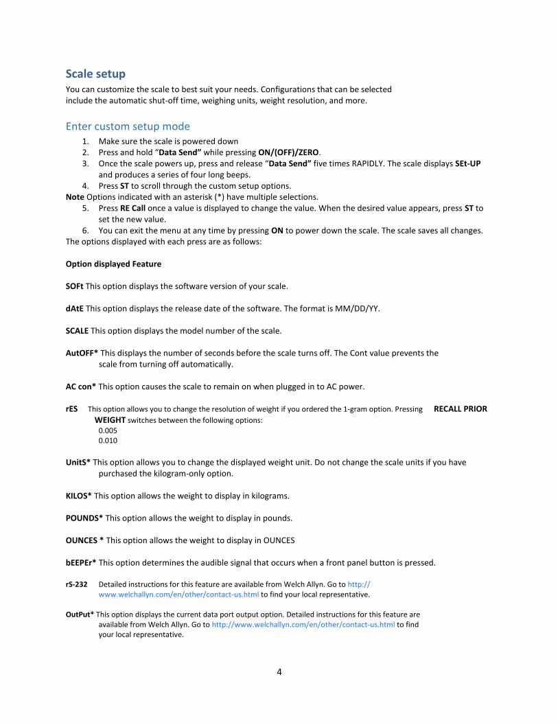
Scale setup You can customize the scale to best suit your needs. Configurations that can be selected include the automatic shut-off time, weighing units, weight resolution, and more.
Enter custom setup mode 1. Make sure the scale is powered down 2. Press and hold “Data Send” while pressing ON/(OFF)/ZERO. 3. Once the scale powers up, press and release “Data Send” five times RAPIDLY. The scale displays SEt-UP
and produces a series of four long beeps. 4. Press ST to scroll through the custom setup options.
Note Options indicated with an asterisk (*) have multiple selections. 5. Press RE Call once a value is displayed to change the value. When the desired value appears, press ST to
set the new value. 6. You can exit the menu at any time by pressing ON to power down the scale. The scale saves all changes.
The options displayed with each press are as follows: Option displayed Feature SOFt This option displays the software version of your scale. dAtE This option displays the release date of the software. The format is MM/DD/YY. SCALE This option displays the model number of the scale. AutOFF* This displays the number of seconds before the scale turns off. The Cont value prevents the scale from turning off automatically. AC con* This option causes the scale to remain on when plugged in to AC power. rES This option allows you to change the resolution of weight if you ordered the 1-gram option. Pressing RECALL PRIOR
WEIGHT switches between the following options:
0.005 0.010
UnitS* This option allows you to change the displayed weight unit. Do not change the scale units if you have
purchased the kilogram-only option. KILOS* This option allows the weight to display in kilograms. POUNDS* This option allows the weight to display in pounds. OUNCES * This option allows the weight to display in OUNCES bEEPEr* This option determines the audible signal that occurs when a front panel button is pressed. rS-232 Detailed instructions for this feature are available from Welch Allyn. Go to http:// www.welchallyn.com/en/other/contact-us.html to find your local representative. OutPut* This option displays the current data port output option. Detailed instructions for this feature are available from Welch Allyn. Go to http://www.welchallyn.com/en/other/contact-us.html to find your local representative.
5
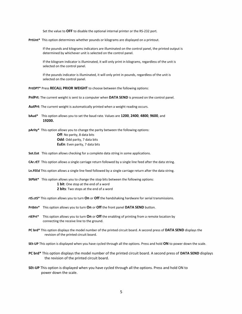
Set the value to OFF to disable the optional internal printer or the RS-232 port.
PrtUnt* This option determines whether pounds or kilograms are displayed on a printout. If the pounds and kilograms indicators are illuminated on the control panel, the printed output is determined by whichever unit is selected on the control panel. If the kilogram indicator is illuminated, it will only print in kilograms, regardless of the unit is selected on the control panel. If the pounds indicator is illuminated, it will only print in pounds, regardless of the unit is selected on the control panel.
PrtOPT* Press RECALL PRIOR WEIGHT to choose between the following options:
PnlPrt: The current weight is sent to a computer when DATA SEND is pressed on the control panel.
AutPrt: The current weight is automatically printed when a weight reading occurs.
bAud* This option allows you to set the baud rate. Values are 1200, 2400, 4800, 9600, and
19200. pArity* This option allows you to change the parity between the following options:
Off: No parity, 8 data bits
Odd: Odd parity, 7 data bits
EuEn: Even parity, 7 data bits
Sot.Eot This option allows checking for a complete data string in some applications. CAr.rET This option allows a single carriage return followed by a single line feed after the data string. Ln.FEEd This option allows a single line feed followed by a single carriage return after the data string. StPbit* This option allows you to change the stop bits between the following options:
1 bit: One stop at the end of a word
2 bits: Two stops at the end of a word
rtS.ctS* This option allows you to turn On or Off the handshaking hardware for serial transmissions.
Prtbtn* This option allows you to turn On or Off the front panel DATA SEND button.
rtEPrt* This option allows you to turn On or Off the enabling of printing from a remote location by
connecting the receive line to the ground.
PC brd* This option displays the model number of the printed circuit board. A second press of DATA SEND displays the
revision of the printed circuit board.
SEt-UP This option is displayed when you have cycled through all the options. Press and hold ON to power down the scale. PC brd* This option displays the model number of the printed circuit board. A second press of DATA SEND displays
the revision of the printed circuit board. SEt-UP This option is displayed when you have cycled through all the options. Press and hold ON to power down the scale.

6
Enter Advanced Service Mode
1. Make sure the scale is powered down 2. Press and hold “Kilo/Pounds” while pressing ON/(OFF)/ZERO. 3. Once the scale powers up, press and release “DATA SEND” five times RAPIDLY. The scale displays SEt-UP
and produces a series of four long beeps. 4. Press the “DATA SEND” button 5. The "RECALL PRIOR WEIGHT" pushbutton is used to select the particular option value. 6. Once this value is selected the scale can be advanced to the next option by again pressing the “DATA
SEND” pushbutton or it can be shut-off by pressing and holding the "ON / (OFF) / ZERO" pushbutton.
Menu List for Advanced Service Mode
1. “A/D”, and next window on display will show the raw A/D reading. As you press on the Platform the A/D
reading will chance. The weight chance reading should be positive proportionally with the applied weight
in pounds.
2. “Test”, and the next window will start displaying the display test, Number will show across from 0 to 9
and repeat w/ DP, from right side to left side.
3. “Pr-OnS” = Power on start-up, next display will show the number of times the “ON” pushbutton has been
depressed.
4. “Pr-rcl” = Powered by Recall, next display will show the number of times the “RECALL” pushbutton has
powered-up the scale (from an off state).
5. “COUntS” = Weighing Counts, next display will show the number of times a weight reading has been
achieved.
6. “rEcntS” = Reweigh counts, next display will show the number of times “Reweigh” pushbutton has been
depressed.
7. “rECLLS” = recalls, next display will show the number of times the “RECALL” pushbutton has been
depressed.
8. “OFFS” = Turned Off, next display will show the number of times the scale has been turned off by holding
the “ON” pushbutton down.
9. “PrintS” = Prints, next display will show the number of times the “Print” pushbutton has been depressed.
10. “SEtUPS” = set-up mode, next display will show the number of times the unit has entered into the set-up
mode.
11. “SEruES” = service mode, next display will show the number of times the unit has entered into the service
mode.
12. “CALS” = Cal mode, next display will show the number of times the unit has entered into the Cal mode.

7
Support services If you have a problem with the device that you cannot resolve, call the Welch Allyn Technical Support Center nearest you for assistance. A representative will assist you in troubleshooting the problem and will make every effort to solve the problem over the phone, potentially avoiding an unnecessary return. Technical support is available 9am-5pm EST.. Welch Allyn offers the following technical support services:
• Telephone support • Replacement service parts • Product service
For information on any of these services, go to www.welchallyn.com/en/servicesupport.html.
Warranty Welch Allyn will warranty the weight scale to be free of defects in material and workmanship and to perform in accordance with manufacturer specifications for the period of one year from the date of retail purchase. The warranty period shall start on the date of purchase. The date of purchase is: 1) the invoiced ship date if the device was purchased directly from Welch Allyn, 2) the date specified during product registration, 3) the date of purchase of the product from a Welch Allyn authorized distributor as documented from a receipt from said distributor. This warranty does NOT cover damages caused by misuse or abuse, including but not limited to:
• Failure caused by unauthorized repairs or modifications • Damage caused by shock or dropping during transportation • Damage caused by improper use of the power supply • Failure caused by improper operation not consistent with the instructions stated in this Directions for use
Should this device require maintenance (or replacement at our option) under warranty, contact your local Welch Allyn representative: http://www.welchallyn.com/en/other/ contact-us.html

8
Repairs
A Welch Allyn Service Center or Authorized Service Provider must perform all repairs on products under warranty unless you are a properly trained technician. CAUTION Unauthorized repairs will void the product warranty. Qualified service personnel or a Welch Allyn Service Center should repair products out of warranty. If you are advised to return a product to Welch Allyn for repair or routine maintenance, schedule the repair with the service center nearest you.
Returning products
When returning a product to Welch Allyn for service, ensure that you have the following information:
a. Product name, model number, and serial number. This information may be found on the product and serial number labels.
b. A complete return shipping address. c. A contact name and phone number. d. Any special shipping instructions. e. A purchase-order number or credit-card number if the product is not covered by a
warranty. f. A full description of the problem or service request.
1. Obtain an RMA number. Contact Welch Allyn and request.
Note: Welch Allyn does not accept returned products without an RMA. 2. Ship the device to Welch Allyn, observing these packing guidelines:
Remove from the device the battery, all hoses, connectors, cables, sensors, power cords, and other ancillary products and equipment, except those items that might be associated with the problem.
Dispose of damaged or leaking batteries in an environmentally safe manner consistent with local regulations.
Note: To ensure safe receipt of your device by the service center and to expedite processing and return of the device to you, thoroughly clean all residue from the device before you ship it to Welch Allyn. For cleaning requirements, see the Cleaning instruction in the Directions for Use. Welch Allyn thoroughly cleans all returned devices on receipt, but any device that cannot be adequately cleaned cannot be repaired. 3. Write the Welch Allyn RMA number with the Welch Allyn address on the outside of the shipping carton.

9
Warranty service
All repairs on products under warranty must be performed or approved by Welch Allyn. Refer all warranty service to Welch Allyn Product Service or another authorized Welch Allyn Service Center. Obtain a Return Material Authorization (RMA) number for all returns to Welch Allyn Product Service. CAUTION Unauthorized repairs will void the product warranty.
Non-warranty service Welch Allyn Product Service Centers and Authorized Service Providers support non-warranty repairs. Contact any Welch Allyn regional service center for pricing and service options. Welch Allyn offers modular repair parts for sale to support non-warranty service. This service must be performed only by qualified end-user biomedical/clinical engineers.
Scale Technical Description WELCH ALLYN SECOND GENERATION SCALES utilize the latest developments in electronic scales and microcomputer technology, engineered to be easy to use. This section describes the technical aspects of these scales. LOAD CELL TRANSDUCERS The function of the load cell transducer is to convert the weight applied to the weighing platform into an electrical signal for further processing and subsequent display by the readout. WELCH ALLYN uses proprietarily designed load cells in most of the scales to optimize performance and reliability. One of three types of load cell transducers may be used in your WELCH ALLYN scale depending on the model number. MODELS 4802D The load cell employed in the model 4802D is referred to as a "Double Ended Bending Beam" ("DEBB")”. It is constructed as a double bending beam with two strain gauges, forming a "half-bridge", mounted on each end of the beam, where the bending takes place in response to weight applied. The ends are interconnected to form the equivalent of a complete "Wheatstone bridge" configuration. Additional calibration and temperature compensating resistors are added in the DEBB's internal wiring. SCALE ELECTRONICS Scale electronics consist of the following:
1. Differential signal amplification. 2. Additional amplification and signal filtering. 3. Analog-to-Digital (A/D) converter and Clock circuit. 4. Battery and support circuitry, voltage regulators, power supplies, etc. 5. Microcomputer and support circuitry. 6. Display board.

10
7. Printer assembly. 8. Printer interface board. 9. Printer controller board.
DIFFERENTIAL SIGNAL AMPLIFICATION The weight dependent output signal produced by the load cell transducers in the weighing frame is a “differential signal”, meaning it is the voltage difference between the “+ Signal” and “- Signal” leads. Integrated circuit U4, an instrumentation amplifier, is used to interface to this differential signal and amplify it. The output signal from the load cells is applied to the protection network consisting of diodes CR4/CR5/CR6/CR7. These diodes prevent destructive high voltages caused by static discharges from damaging U4. A high frequency filter, formed by L1/L2/C9, C10 couples the weight signal to the input of U4. In U4 the differential signal is amplified by a factor of 100, and converted to a “ground-referenced” voltage for further processing. Capacitors C16/C17/C24 provide local bypassing of the power supplies used by instrumentation amplifier U4. Capacitor C18 furnished compensation of U4 by reducing amplification at higher frequencies. ANALOG-TO-DIGITAL (A/D) CONVERSION Integrated circuit U6 is the analog-to-digital converter. Included on this integrated circuit are auto-zero functions, auto-polarity, and the digital and analog functions necessary to perform dual slope integration conversion to 20,000 counts (4-1/2 digits). The weight signal voltage is applied to the analog input (pin 10) of U6. A reference voltage for the conversions is applied to pin 2 of U6. The reference voltage, nominally 1 Volt, is derived from the load cell transducer excitation voltage, by the divider network consisting of resistors R29, R30 and potentiometer P1. Adjusting p1 sets the “span” or weight calibration of the scale. The system clock, applied at pin 22 of U6, is used to precisely time and control the phases of the dual slope conversion process. Refer to the converter time diagram when reading the following description.

11
A/D CONVERTER TIMING DIAGRAM PHASE 1, AUTO ZERO During auto zero, the errors in the analog components (offset voltages of buffers, comparators, etc.) will be automatically nulled out. This is performed by internal logic that disconnects the input pins (9 & 10) from the applied analog signal, connects them to ground, then closes an internal feedback loop such that offset error information is stored in the “auto zero” capacitor, C21. Also during this phase, “reference capacitor” C22 is charged to the voltage present on “Vref” (pin 2 of U6). PHASE 2, SIGNAL INTEGRATE The input signal is reconnected and then integrated for exactly 10,000 clock pulses. On completion of the integration period, the voltage V is directly proportional to the input voltage, corresponding to the weight applied to the scale. Capacitor C20 is the integration capacitor, with resistor R32 setting the integration current. At the end of this phase the input signal polarity is determined. PHASE 3, REF. INTEGRATE, SIGNAL DE-INTEGRATE The input to the integrator is switched from the input signal to reference capacitor C22. Internal switches connect capacitor C22 to the integrator input so that its polarity is opposite that of the previously applied input signal. This causes the integrator to discharge back towards zero. The number of clock pulses counted between the beginning of this cycle and the time when the integrator output passes through zero is a digital measure of the magnitude of the input signal. This count is stored in an internal latch on U6 for output to the microcomputer. ZERO INTEGRATOR PHASE One minor additional phase is included to insure that the integration capacitor C20 is fully discharged to zero volts. This typically lasts 100-200 counts. CLOCK CIRCUIT A clock is required for the A/D converter, integrated circuit U6. A clock signal is generated internally in microcomputer U7 and appears on port pin “P1.0”. The frequency is internally set by the microcomputer’s software and is nominally 120 KHz. POWER SWITCHING, VOLTAGE REGULATION AND SUPPORT CIRCUITRY Depending upon their configuration, WELCH ALLYN second generation scales contains disposable primary cells. Additional circuitry is included to switch the battery supply, provide voltage regulation and detect low battery voltage conditions. BATTERY SWITCHING In order to conserve battery life the battery supply is switched on and off as needed by the scale. Transistor Q1 is a series switch which applies battery voltage to the remainder of the circuitry. Q1 is controlled by transistor Q2, which, in turn, is controlled by "watchdog timer" circuit U11. To initiate power-on Q1 is turned on through momentary closure of membrane pushbutton S1 ("ON / (OFF) / ZERO") and diode D2 (located on display board 48901/500043); diode D1 (located on display board) is used to signal input pin "P2" of I/O expander U4 (also on display board) that pushbutton switch S1 is pressed. A secondary turn-on circuit occurs through diode D4 (located on the display board) and pushbutton S4 ("RECALL PRIOR WEIGHT") to allow display of the previously stored weight if the scale is presently turned "off". The pushbutton closure is also coupled through diode D3 (located on the display board) to signal input pin "P1" of I/O expander U4 (located on the display board) that the "RECALL PRIOR WEIGHT" pushbutton is pressed.
12
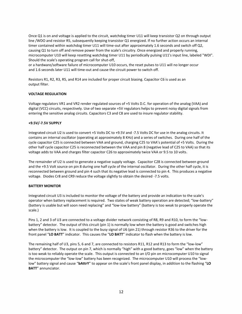
Once Q1 is on and voltage is applied to the circuit, watchdog timer U11 will keep transistor Q2 on through output line /WDO and resistor R5, subsequently keeping transistor Q1 energized. If no further action occurs an internal timer contained within watchdog timer U11 will time-out after approximately 1.6 seconds and switch off Q2, causing Q1 to turn off and remove power from the scale's circuitry. Once energized and properly running, microcomputer U10 will keep resetting watchdog timer U11 by periodically pulsing U11's input line, labeled "WDI". Should the scale's operating program call for shut-off, or a hardware/software failure of microcomputer U10 occurs, the reset pulses to U11 will no longer occur and 1.6 seconds later U11 will time-out and cause the circuit power to switch off. Resistors R1, R2, R3, R5, and R14 are included for proper circuit biasing. Capacitor C6 is used as an output filter. VOLTAGE REGULATION Voltage regulators VR1 and VR2 render regulated sources of +5 Volts D.C. for operation of the analog (VAA) and digital (VCC) circuits, respectively. Use of two separate +5V regulators helps to prevent noisy digital signals from entering the sensitive analog circuits. Capacitors C3 and C8 are used to insure regulator stability. +9.5V/-7.5V SUPPLY Integrated circuit U2 is used to convert +5 Volts DC to +9.5V and -7.5 Volts DC for use in the analog circuits. It contains an internal oscillator (operating at approximately 8 KHz) and a series of switches. During one half of the cycle capacitor C25 is connected between VAA and ground, charging C25 to VAA’s potential of +5 Volts. During the other half cycle capacitor C25 is reconnected between the VAA and pin 8 (negative lead of C25 to VAA) so that its voltage adds to VAA and charges filter capacitor C26 to approximately twice VAA or 9.5 to 10 volts. The remainder of U2 is used to generate a negative supply voltage. Capacitor C28 is connected between ground and the +9.5 Volt source on pin 8 during one half cycle of the internal oscillator. During the other half cycle, it is reconnected between ground and pin 4 such that its negative lead is connected to pin 4. This produces a negative voltage. Diodes Cr8 and CR9 reduce the voltage slightly to obtain the desired -7.5 volts. BATTERY MONITOR Integrated circuit U3 is included to monitor the voltage of the battery and provide an indication to the scale’s operator when battery replacement is required. Two states of weak battery operation are detected; “low-battery” (battery is usable but will soon need replacing” and “low-low battery” (battery is too weak to properly operate the scale.) Pins 1, 2 and 3 of U3 are connected to a voltage divider network consisting of R8, R9 and R10, to form the “low-battery” detector. The output of this circuit (pin 1) is normally low when the battery is good and switches high when the battery is low. It is coupled to the busy signal of U6 (pin 21) through resistor R36 to the driver for the front panel “LO BATT” indicator. This causes the “LO BATT” indicator to flash when the battery is low. The remaining half of U3, pins 5, 6 and 7, are connected to resistors R11, R12 and R13 to form the “low-low” battery” detector. The output on pin 7, which is normally “high” with a good battery, goes “low” when the battery is too weak to reliably operate the scale. This output is connected to an I/O pin on microcomputer U10 to signal the microcomputer the “low-low” battery has been recognized. The microcomputer U10 will process the “low-low” battery signal and cause “bAttrY” to appear on the scale’s front panel display, in addition to the flashing “LO BATT” annunciator.

13
MICROCOMPUTER AND SUPPORT CIRCUITS To attain various additional features such as automatic zero tare, pounds/kilograms conversion, weight lock-in, previous weight memory, etc., a microcomputer is employed to additionally process the data supplied by the A/D converter. This microcomputer system consists of U10, a microcomputer; U9, a non-volatile memory which stores the previous weight reading; and U11, a device to generate reset conditions for the microcomputer. During operation of the scale the microcomputer continually receives the weight readings from the A/D converter. This data is received in a “multiplexed” format (one digit at a time) from the output of the A/D converter (microcomputer input lines P1.1 through P1.7). The microcomputer also continually scans the keyboard (using U4) looking for closed switches. If a key press is sensed, the microcomputer executes whatever action is called for in its program. After processing the A/D data, the microcomputer assembles it for viewing and transfers it to the front panel display. U10 is a complete microcomputer, containing a software program stored in read-only memory, read/write memory for temporary storage of program variables, an arithmetic logic unit, input/output and other control lines, etc. Crystal XTAL1 and capacitors C29/C30 form the clock oscillator which controls the internal timing of the microcomputer. THE I2C SERIAL DATA BUS The 4802 Pediatric Scale makes extensive use of serial data transmission to send data to the display, read the keyboard status, read/write information to the non-volatile memory, etc. This particular serial data format is referred to as "I2C", which stands for "Inner-integrated circuit". This bus consists of only two wires, which are labeled "SDA" (serial data), and "SCL" (serial clock). Multiple integrated circuit devices can be attached to the same I2C serial bus. A device will only activate when its specific address is sent. Each device has a unique pre-assigned address (inherent to the specific type of integrated circuit) plus additional pins to set a unique address for multiple devices of the same type. By manipulation of the SCL and SDA lines, the master device controlling the I2C bus (in this case microcomputer U10) can send and receive data to all the other devices on the bus. Specific timing of the SDA and SCL lines can also reset, start, and stop transmission to devices attached to the bus. NON-VOLATILE MEMORY The internal memory of microcomputer U10 does not retain data when the power is switched off. Because some features of the scale may require lasting data retention (such as last weight recall) integrated circuit U is included. This device, called an “electrically erasable programmable read only memory”, or “EEPROM” will store selected information for periods of up to 100 years. Information needed to be stored to or retrieved from U10 Chip and is sent in serial form using the lines SCL (serial clock) and SDA (serial data). These are controlled by microcomputer U10. A data bit (a high or low level) is sent and received on SDA when the SCL line provides a pulse. Resistors R54/R55 are provided as pull-ups on the SCL/SDA lines to insure the data and clock pulses are properly shaped. Capacitor C36 improves power supply bypassing. RESET GENERATION In order for microcomputer U10 to properly execute its software instructions it must be initialized to the start of the program when power is first turned on. Reset pin 9 of U10 will accomplish this when it is set “high”.
14
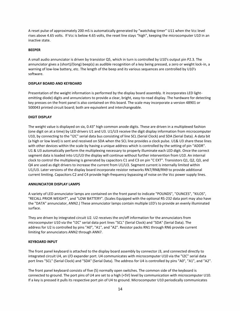
A reset pulse of approximately 200 mS is automatically generated by “watchdog timer” U11 when the Vcc level rises above 4.65 volts. If Vcc is below 4.65 volts, the reset line stays “high”, keeping the microcomputer U10 in an inactive state. BEEPER A small audio annunciator is driven by transistor Q5, which in turn is controlled by U10's output pin P2.3. The annunciator gives a (short)/(long) beep(s) as audible recognition of a key being pressed, a zero or weight lock-in, a warning of low-low battery, etc. The length of the beep and its various sequences are controlled by U10's software. DISPLAY BOARD AND KEYBOARD Presentation of the weight information is performed by the display board assembly. It incorporates LED light-emitting diode) digits and annunciators to provide a clear, bright, easy-to-read display. The hardware for detecting key presses on the front panel is also contained on this board. The scale may incorporate a version 48901 or 500043 printed circuit board; both are equivalent and interchangeable. DIGIT DISPLAY The weight value is displayed on six, 0.43" high common anode digits. These are driven in a multiplexed fashion (one digit on at a time) by LED drivers U1 and U3. U1/U3 receive the digit display information from microcomputer U10, by connecting to the "I2C" serial data bus consisting of line SCL (Serial Clock) and SDA (Serial Data). A data bit (a high or low level) is sent and received on SDA when the SCL line provides a clock pulse. U1& U3 share these lines with other devices within the scale by having a unique address which is controlled by the setting of pin "ADDR". U1 & U3 automatically perform the multiplexing necessary to properly illuminate each LED digit. Once the correct segment data is loaded into U1/U3 the display will continue without further intervention from U10. An internal clock to control the multiplexing is generated by capacitors C1 and C3 on pin "C EXT". Transistors Q1, Q2, Q3, and Q4 are used as digit drivers to increase the current from U1/U3. Segment current is internally limited within U1/U3. Later versions of the display board incorporate resistor networks RN7/RN8/RN9 to provide additional current limiting. Capacitors C2 and C4 provide high-frequency bypassing of noise on the Vcc power supply lines. ANNUNCIATOR DISPLAY LAMPS A variety of LED annunciator lamps are contained on the front panel to indicate "POUNDS", "OUNCES", "KILOS", "RECALL PRIOR WEIGHT", and "LOW BATTERY". (Scales Equipped with the optional RS-232 data port may also have the "DATA" annunciator, ANN2.) These annunciator lamps contain multiple LED's to provide an evenly illuminated surface. They are driven by integrated circuit U2. U2 receives the on/off information for the annunciators from microcomputer U10 via the "I2C" serial data port lines "SCL" (Serial Clock) and "SDA" (Serial Data). The address for U2 is controlled by pins "A0", "A1", and "A2". Resistor packs RN1 through RN6 provide current limiting for annunciators ANN2 through ANN7. KEYBOARD INPUT The front panel keyboard is attached to the display board assembly by connector J3, and connected directly to integrated circuit U4, an I/O expander port. U4 communicates with microcomputer U10 via the "I2C" serial data port lines "SCL" (Serial Clock) and "SDA" (Serial Data). The address for U4 is controlled by pins "A0", "A1", and "A2". The front panel keyboard consists of five (5) normally open switches. The common side of the keyboard is connected to ground. The port pins of U4 are set to a high (+5V) level by communication with microcomputer U10. If a key is pressed it pulls its respective port pin of U4 to ground. Microcomputer U10 periodically communicates

15
with U4 to look at the condition of the switches on the front panel. A closed switch will be detected by U10's software. If the switch remains closed for a period of time it will be validated by U10 ("debounced") and the appropriate action called for will be executed. Diodes D1 and D3 are used to turn the scale "on" when either the front panel "ON / (OFF) / ZERO" or the "RECALL PRIOR WEIGHT" pushbuttons are pressed. They connect the "ON" line present on the expansion bus connector J1 to ground momentarily to cause the power to the instrument board to become active. Diodes D2 and D4 are included to couple the pushbutton closures to I/O expander U4 so that the microcomputer U10 can determine which pushbutton has been activated and take the appropriate action. POWER SUPPLY The power supply is mounted external to the scale cabinet on the rear panel. It is connected to the scale via a removable power input connector. A hospital grade line cord and plug is provided. The power supply is a separate sealed medical power supply with UL and other certifications. It is a universal power supply capable of operating from 100 to 240 volts with no switching or chance in connections required. For 240-volt operation the line cord and plug must be replaced with the appropriate cord for the country of use. The output voltage is 12 volts DC.
Maintenance of Scales Routinely perform the following preventive maintenance to keep your scale in working order.
1. Check the calibration annually or as required.
2. Inspect the scale/cradle for cracks or loose mounting hardware. Replace or repair as necessary.
3. Visually inspect the scale/cradle enclosure for damage or loose or missing hardware. Replace or repair as necessary.
4. If equipped, inspect the AC line cord for abrasions or other signs of wear.
5. Do not expose the scale/cradle to excessive water or moisture.
6. Do not store the scale/cradle where heavy objects can be placed on it.
7. Replace the batteries annually or as required.
8. Do not service or perform maintenance while the scale is in use with a patient.
Battery replacement
CAUTION Use only size D disposable alkaline batteries. The use of any other battery will void the warranty. 1. Remove the cradle from the scale. 2. Remove the top cover of the enclosure by removing the eight hex screws with a 1/8-inch allen wrench. 3. Install six new size D batteries in the battery holder. Make sure to follow the polarity instructions. 4. Re-attach the top cover of the enclosure by installing the eight hex screws. Make sure the operation label is facing the correct direction.
16
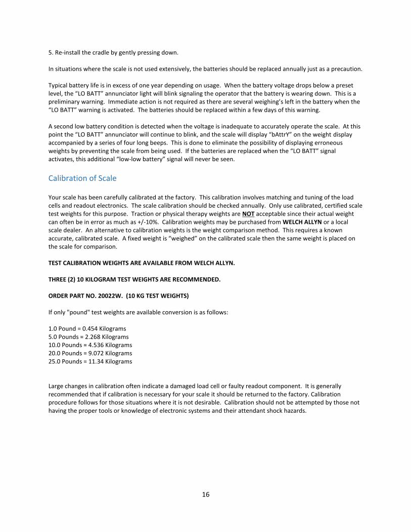
5. Re-install the cradle by gently pressing down. In situations where the scale is not used extensively, the batteries should be replaced annually just as a precaution. Typical battery life is in excess of one year depending on usage. When the battery voltage drops below a preset level, the “LO BATT” annunciator light will blink signaling the operator that the battery is wearing down. This is a preliminary warning. Immediate action is not required as there are several weighing’s left in the battery when the “LO BATT” warning is activated. The batteries should be replaced within a few days of this warning. A second low battery condition is detected when the voltage is inadequate to accurately operate the scale. At this point the “LO BATT” annunciator will continue to blink, and the scale will display “bAttrY” on the weight display accompanied by a series of four long beeps. This is done to eliminate the possibility of displaying erroneous weights by preventing the scale from being used. If the batteries are replaced when the “LO BATT” signal activates, this additional “low-low battery” signal will never be seen.
Calibration of Scale Your scale has been carefully calibrated at the factory. This calibration involves matching and tuning of the load cells and readout electronics. The scale calibration should be checked annually. Only use calibrated, certified scale test weights for this purpose. Traction or physical therapy weights are NOT acceptable since their actual weight can often be in error as much as +/-10%. Calibration weights may be purchased from WELCH ALLYN or a local scale dealer. An alternative to calibration weights is the weight comparison method. This requires a known accurate, calibrated scale. A fixed weight is “weighed” on the calibrated scale then the same weight is placed on the scale for comparison. TEST CALIBRATION WEIGHTS ARE AVAILABLE FROM WELCH ALLYN. THREE (2) 10 KILOGRAM TEST WEIGHTS ARE RECOMMENDED. ORDER PART NO. 20022W. (10 KG TEST WEIGHTS) If only "pound" test weights are available conversion is as follows: 1.0 Pound = 0.454 Kilograms 5.0 Pounds = 2.268 Kilograms 10.0 Pounds = 4.536 Kilograms 20.0 Pounds = 9.072 Kilograms 25.0 Pounds = 11.34 Kilograms Large changes in calibration often indicate a damaged load cell or faulty readout component. It is generally recommended that if calibration is necessary for your scale it should be returned to the factory. Calibration procedure follows for those situations where it is not desirable. Calibration should not be attempted by those not having the proper tools or knowledge of electronic systems and their attendant shock hazards.

17
Calibration Procedure
Preparing the Scale for Calibration
1. Unplug the scale from the AC line. 2. Remove the cradle from the scale. 3. Detach the top cover of the scale's enclosure by removing the eight (8) #10 button head screws.
4. The scale's instrument board should now be in full view. Note the location of the trimmer potentiometer, "P1 Span".
Enter the “calibration mode” by following exactly the procedure outlined below:
1. Be sure scale is off. The scale should be placed on a flat, level surface.
2. Press and hold the "REWEIGH" pushbutton.
3. While pressing the "REWEIGH" pushbutton press and release the "ON / OFF / ZERO" pushbutton.
4. The " Send Data" pushbutton is a special hidden programming and test pushbutton located under the SCALE-TRONIX® logo "RECALL PRIOR WEIGHT" pushbutton. After the scale displays the test pattern of "888888" release the "REWEIGH" button and press the "Send Data" pushbutton five (5) times. This will cause the readout to enter the calibration mode. The display will indicate "CAL".
5. Press the ("Send Data") pushbutton once more; the display will indicate "A-d". This indicates the start of the "raw" analog-to-digital converter data being inputted to the microprocessor.
6. Press the " Send Data" pushbutton one more time. The number displayed is now the "raw" analog to digital data. Each "count" of the display is equivalent to 1 gram.
7. The automatic turn-off timer has also been programmed for an extended "on" period to give you time to calibrate the scale. This time period is three minutes. The scale may be turned off before this time period by simply pressing and holding the "ON / (OFF) / ZERO" pushbutton. Hold it in for several seconds until the power shuts off. If additional time is needed to complete the calibration procedure, press the "ON / (OFF) / ZERO" pushbutton briefly. This will reset the timer for an additional three minutes. (This does not apply if the scale is being powered by an external DC power supply, since it will remain on continuously.) The readout is now displaying a number, which represents the zero offset value of the platform and load cell transducers, in kilograms (0.001 kilogram = 1 (gram). 1. Momentarily press the "ON / (OFF) / ZERO" pushbutton to reset the internal self-test timer. Reattach
the scale's cradle. Note the currently displayed weight reading on the front display. Record this zero offset reading.
2. Lay the two (2) 10-kilogram test weights side by-side in the center of the cradle. Note the new number displayed. Subtract the original zero offset value from this new number to obtain the scale's displayed value of the calibration weight. Example: The zero offset value is "-1.230 KILOS" (representing -1.230 Kilograms). Adding the specified two 10-kilogram test weights (equivalent to 20.000 kilograms) to the cradle produces a reading of "18.763 KILOS". The difference is 18.763 - (-1.230) = 19.993 (equivalent to 19.993 kilograms). This
18
would indicate the calibration is 20.000 - 19.993 = 0.007 kilograms "low". Using the specified two 10-kilogram test weights a difference of 20.000 kilograms +/-0.003 kilograms (3 grams) should be obtained. If necessary, adjust potentiometer P1 (span adj.) on the instrument board until the correct value is obtained. If the display shows "Ad our" (A/D over range), try repeating the process with a single 10-kilogram weight until the calibration becomes close; the calibration can then be "fine-tuned" with both 10 kilogram weights. (If using weights other than the two specified 10 kilograms, make the necessary adjustments to the calibration procedure.)
3. Momentarily press the "ON / (OFF) / ZERO" pushbutton to reset the internal self-test timer. Remove the test weight and recheck the zero offset value. Note that adjusting P1 SPAN may also alter the zero offset value. Repeat the process as necessary to obtain the correct difference.
4. Now you may turn the scale off by pressing the "ON / (OFF) / ZERO" pushbutton and holding it in for a few seconds. That will force it to turn off. Re-attach the top cover of the enclosure using an Allen wrench and the eight (8) #10 button head screws. Replace the cradle. The scale may now be checked for normal operation with the test weights.
19
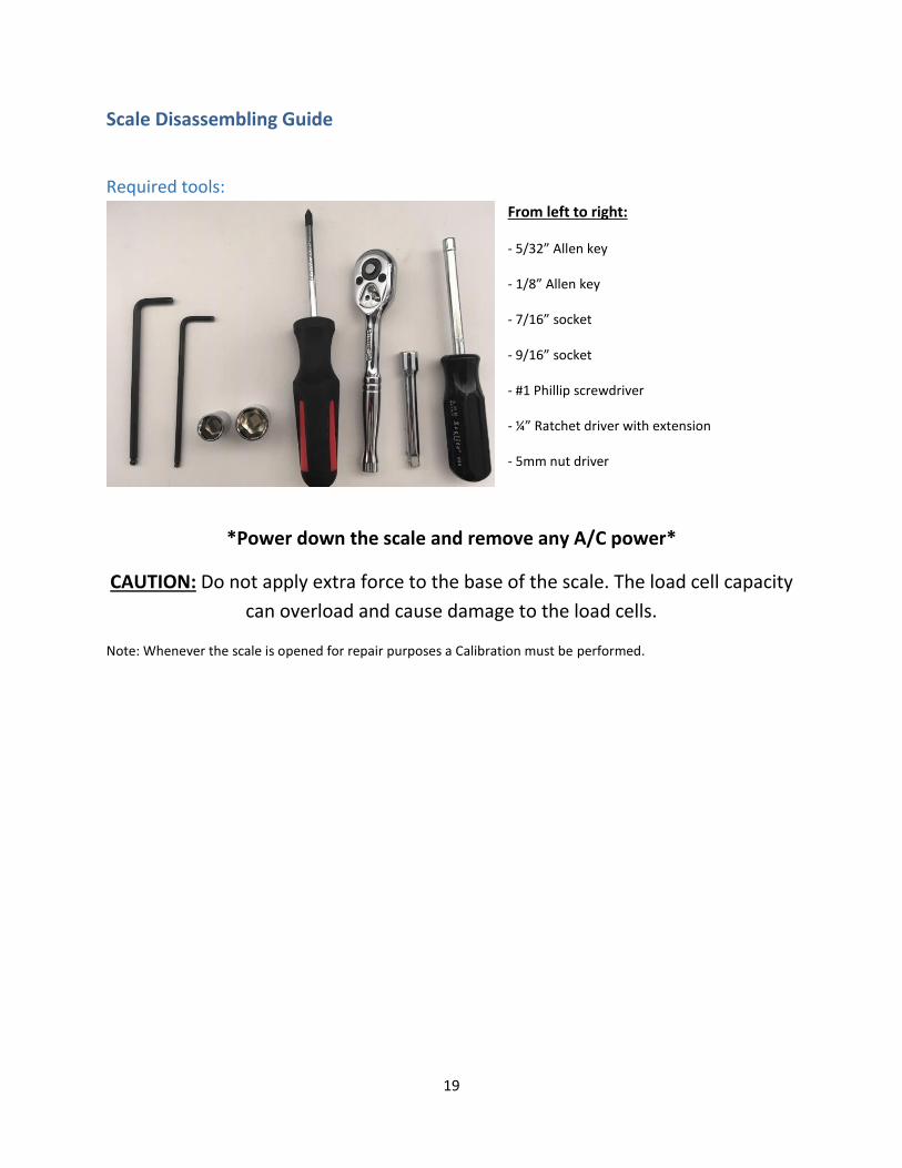
Scale Disassembling Guide
Required tools:
From left to right:
- 5/32” Allen key
- 1/8” Allen key
- 7/16” socket
- 9/16” socket
- #1 Phillip screwdriver
- ¼” Ratchet driver with extension
- 5mm nut driver
*Power down the scale and remove any A/C power*
CAUTION: Do not apply extra force to the base of the scale. The load cell capacity
can overload and cause damage to the load cells.
Note: Whenever the scale is opened for repair purposes a Calibration must be performed.

20
Scale Disassembling
1. Remove the cradle by lifting straight up.
2. Use a 1/8” Allen wrench to remove the 8 screws on the top plate
3. Remove batteries

21
4. Disconnect the wire harness from the Main Board
5. Disconnect J4
6. Disconnect J14
22
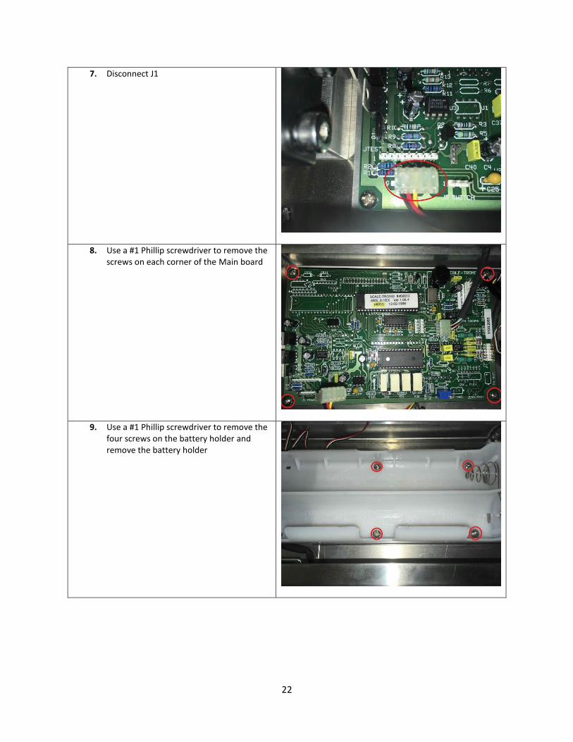
7. Disconnect J1
8. Use a #1 Phillip screwdriver to remove the screws on each corner of the Main board
9. Use a #1 Phillip screwdriver to remove the four screws on the battery holder and remove the battery holder
23
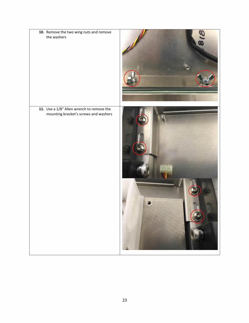
10. Remove the two wing nuts and remove the washers
11. Use a 1/8” Allen wrench to remove the mounting bracket’s screws and washers

24
12. Disconnect J1 & J3 on the Display Board
13. Use a #1 Phillip screwdriver to remove the four screws on the display board
14. Use a 5/32” Allen wrench to remove the four screws on the load beam
CAUTION: Do not apply extra force to the base of
the scale. The load cell capacity can overload and
cause damage to the load cells.

25
15. Use a 1/8” Allen wrench to remove the handles by removing the screws. Use a 7/16” socket to remove the nuts to remove the handle

26
16. Disconnect the power jack on the AC power assembly
17. Use a #1 Phillip screwdriver to remove the screw on the assembly
18. Use a 9/16” socket to remove the nut on the AC power jack

27
19. Use a 5 mm nut driver to remove the two nuts on the RS 232 Data Port
Troubleshooting
Scale Troubleshooting The following simplified troubleshooting procedures are recommended for identifying defective system components. Certain corrective measures are provided. More complicated servicing should only be performed by the factory or authorized service facilities. Most problems can be solved over the telephone. Problems requiring factory service are usually handled quickly and the scale is on its way back. Call first to discuss the problem. DISPLAY DOES NOT ILLUMINATE Verify the scale is plugged in. Check that known good Duracell alkaline cells are properly installed in the battery holder. Check that the cable between the display board and instrument board is connected. Check that the membrane keyboard is connected to the display board. Measurements of the D.C supply voltages can be made with a Digital Volt Meter or analog multimeter. WEIGHT READING NOT ACCURATE This can commonly be caused by a mechanical obstruction of the weighing platform. Check that the platform is not touching some foreign object so that it is restricted in its’ downward movement. Also check that the connecting cable is firmly plugged into the instrument circuit board (marked “J4 LOAD CELL”). + WEIGHT READING TAKES EXCESSIVE TIME TO DISPLAY If the cradle is in motion the scale will wait for it to settle before displaying the weight. This can be caused by excessive patient motion. Also check that the transducer cable is firmly plugged into the instrument board. Examine that the cradle is not rubbing against a foreign object. Check that the scale is not subject to excessive vibration or breezes from overhead fans or ventilation outlets.
28
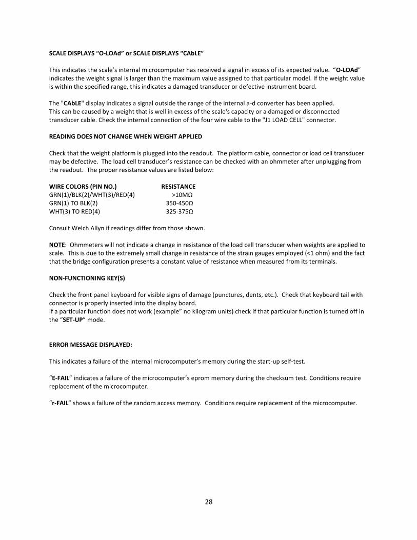
SCALE DISPLAYS “O-LOAd” or SCALE DISPLAYS “CAbLE” This indicates the scale’s internal microcomputer has received a signal in excess of its expected value. “O-LOAd” indicates the weight signal is larger than the maximum value assigned to that particular model. If the weight value is within the specified range, this indicates a damaged transducer or defective instrument board. The "CAbLE" display indicates a signal outside the range of the internal a-d converter has been applied. This can be caused by a weight that is well in excess of the scale's capacity or a damaged or disconnected transducer cable. Check the internal connection of the four wire cable to the "J1 LOAD CELL" connector. READING DOES NOT CHANGE WHEN WEIGHT APPLIED Check that the weight platform is plugged into the readout. The platform cable, connector or load cell transducer may be defective. The load cell transducer’s resistance can be checked with an ohmmeter after unplugging from the readout. The proper resistance values are listed below: WIRE COLORS (PIN NO.) RESISTANCE GRN(1)/BLK(2)/WHT(3)/RED(4) >10MΩ GRN(1) TO BLK(2) 350-450Ω WHT(3) TO RED(4) 325-375Ω Consult Welch Allyn if readings differ from those shown. NOTE: Ohmmeters will not indicate a change in resistance of the load cell transducer when weights are applied to scale. This is due to the extremely small change in resistance of the strain gauges employed (<1 ohm) and the fact that the bridge configuration presents a constant value of resistance when measured from its terminals. NON-FUNCTIONING KEY(S) Check the front panel keyboard for visible signs of damage (punctures, dents, etc.). Check that keyboard tail with connector is properly inserted into the display board. If a particular function does not work (example” no kilogram units) check if that particular function is turned off in the “SET-UP” mode. ERROR MESSAGE DISPLAYED: This indicates a failure of the internal microcomputer’s memory during the start-up self-test. “E-FAIL” indicates a failure of the microcomputer’s eprom memory during the checksum test. Conditions require replacement of the microcomputer. “r-FAIL” shows a failure of the random access memory. Conditions require replacement of the microcomputer.
29
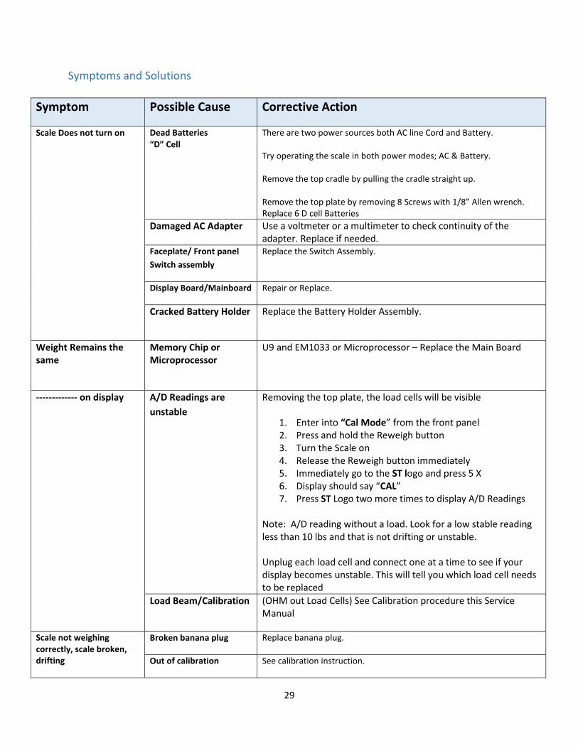
Symptoms and Solutions
Symptom Possible Cause Corrective Action
Scale Does not turn on
Dead Batteries “D” Cell
There are two power sources both AC line Cord and Battery. Try operating the scale in both power modes; AC & Battery. Remove the top cradle by pulling the cradle straight up. Remove the top plate by removing 8 Screws with 1/8” Allen wrench. Replace 6 D cell Batteries
Damaged AC Adapter Use a voltmeter or a multimeter to check continuity of the adapter. Replace if needed.
Faceplate/ Front panel
Switch assembly
Replace the Switch Assembly.
Display Board/Mainboard Repair or Replace.
Cracked Battery Holder Replace the Battery Holder Assembly.
Weight Remains the same
Memory Chip or Microprocessor
U9 and EM1033 or Microprocessor – Replace the Main Board
------------- on display A/D Readings are
unstable
Removing the top plate, the load cells will be visible
1. Enter into “Cal Mode” from the front panel 2. Press and hold the Reweigh button 3. Turn the Scale on 4. Release the Reweigh button immediately 5. Immediately go to the ST logo and press 5 X 6. Display should say “CAL” 7. Press ST Logo two more times to display A/D Readings
Note: A/D reading without a load. Look for a low stable reading less than 10 lbs and that is not drifting or unstable. Unplug each load cell and connect one at a time to see if your display becomes unstable. This will tell you which load cell needs to be replaced
Load Beam/Calibration (OHM out Load Cells) See Calibration procedure this Service Manual
Scale not weighing correctly, scale broken, drifting
Broken banana plug Replace banana plug.
Out of calibration See calibration instruction.

30
Symptom Possible Cause Corrective Action
Bad Load Beam Side to side platform test using 10KG certified weight
Apply weight evenly on the center of the scale. Press “REWEIGH” two times and record your weight reading each time.
Remove weight from center and apply weight on each side one at a time and Press “REWEIGH” two times and record weight reading each time.
Examine your readings
Plot readings and they should be within +/ - 0.4 lb./.2 kg from center reading. The side that reads differently from all others is the problem area. Repeat corner test if need be. Look for obstructions and/or replace the Load Beam if necessary.
Bad A/D Chip
Put the scale in the "Cal" Mode. Press “Data Send” button one more time to show A/D reading.
If stable A/D reading, press platform and watch display for linear reading 10, 20, 30, 40, etc. up to 100.
If unstable A/D reading, it may be a bad Load Cell or a Main Board issue. Replace as necessary
Display says "Cable or O-
Load" Flashes or Beeps
Cable Check Continuity of the Cable and if bad replace.
All the numbers are not lighting up (Missing Segments of the Numbers)
LED Remove the Display Board (see directions above)
1. Gently, lift a Non-working 7 Segment LED chip with a flat head screw driver and exchange with a working LED chip.
2. IF the trouble follows the LED chip replace the chip 3. IF the trouble stays in the socket replace the display
board.
Display Board Repair or Replace.
Main Board Repair or Replace.
Cracked broken Cradle
Assembly
Cleaning with Alcohol Replace the Cradle assembly.
Any other Error Modes Main board, Display Board, Load Beam
Repair or Replace.

31
Repair Parts List
PART NO. DESCRIPTION 411961 ASSY, 4802D SWITCH FP LB-KG 411962 ASSY, 4802D SWITCH FP KG 48106 HANDLE SIDE 48118 FERRULE FOR 3/8" HANDLE 48107 HANDLE REAR 40517 CORD POWER 341003 POWER SUPPLY EXTERNAL 12VDC 66011 FOOT RUBBER 630162 LOAD BEAM ASSEMBLY 4802 710031W HARNESS, RS-232 DATA 600059 BRACKET, 4802 EXTERNAL POWER 725480 SCALE-T LABEL DIAPER WEIGH OPTION 4802D 700059A PCB ASSEMBLY DISPLAY 700056 PCB MAIN 4802 RS-232 (No Firmware Chip) 630225 BATT HLDR W/EXT JACK(12V)- SN 21000 & UP 450012-KIT FIRMWARE V1.06.4 630223 PCB TRAY ASSEMBLY 750046 CABLE ASSEMBLY, DISPLAY 4802 700076 "D" CELL BATTERY 710078W Harness, 12V Ext Power Supply 48200W CRADLE ASSEMBLY STANDARD 25" 48220W CRADLE 4 SIDED FOR 4802D 48222 OVERSIZE CRADLE ASSY SHIP WITH 4802D 48217 Pediatric Scale liners, carton of 500

32
Schematics & Part Diagrams

33
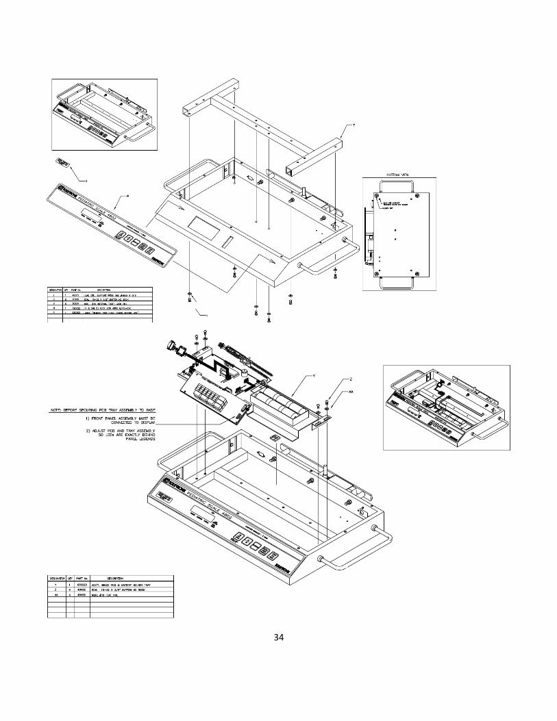
34
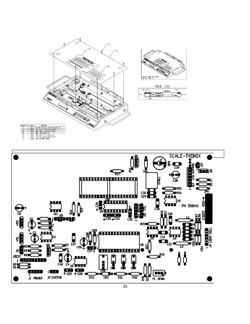
35
PCB ASSEMBLY 700056W

36
PCB ASSEMBLY 700059A
HARNESS ASSEMBLY 710031W