Week 5: Sequential Circuit Design -...
46
Week 5: Sequential Circuit Design
Transcript of Week 5: Sequential Circuit Design -...

Week5:SequentialCircuitDesign

Circuitsusingflip-flops
§ Nowthatweknow aboutflip-flopsand whattheydo,howdo weusethemincircuit design?
§ What’sthebenefitinusing flip-flopsinacircuitatall?
CombinationalCircuit
Inputs Outputs
StorageUnits

Wearehere
Processors
FiniteStateMachines
ArithmeticLogicUnits
Devices
Flip-flops
Circuits
LogicGates Transistors
AssemblyLanguage

Example#1:Registers

Shiftregisters
§ AseriesofDflip-flopscanstoreamulti-bitvalue(suchasa16-bitinteger,forexample).
§ Datacanbeshiftedintothisregisteronebitatatime,over16clockcycles.ú Knownasashiftregister.
D0 Q
Q
D15 Q
Q
D1 Q
Q
D2 Q
Q
Clk
SI

Loadregisters
§ Onecanalsoloadaregister’svaluesallatonce,byfeedingsignalsintoeachflip-flop:ú Inthisexample:a4-bitloadregister.
D Q
Q
D Q
Q
D Q
Q
D Q
Q
Clk
D0 D1 D2 D3

Loadregisters
§ Tocontrolwhenthisregisterisallowedtoloaditsvalues,weintroducetheDflip-flopwithenable:
D Q
Q
EN
D Q
Q
D
EN
Clk

Loadregisters
§ ImplementingtheregisterwiththesespecialDflip-flopswillnowmaintainvaluesintheregisteruntiloverwrittenbysettingENhigh.
D Q
Q
D Q
Q
D Q
Q
D Q
Q
Clk
D0 D1 D2 D3
Write
EN EN EN EN

Example#2:Counters

Counters
§ ConsidertheTflip-flop:ú Outputisinvertedwhen inputTishigh.
§ Whathappenswhena seriesofTflip-flopsare connectedtogether in sequence?
§ Moreinteresting:ú Connecttheoutputof oneflip-floptotheclock inputofthenext!
T Q
Q
D
Clk
Q
Q
T

Counters
§ Thisisa4-bitripplecounter,whichisanexampleofanasynchronouscircuit.ú Timingisn’tquitesynchronizedwiththerisingclockpulse.
ú Cheaptoimplement,butunreliablefortiming.
T Q
Q
T Q
Q
T Q
Q
T Q
Q
Q0 Q1 Q2 Q3 1

Counters
§ Timingdiagram
Q0
C
Q1
Q2
T Q
Q
T Q
Q
T Q
Q
T Q
Q
Q0 Q1 Q2 Q3 1
C
Q3
0
0
0
1
0
0
0
0
1
0
0
0
0
1
0
0
1
1
0
0
0
0
1
0
1
0
1
0
0
1
1
0
1
1
1
0

Counters
§ Thisisasynchronouscounter,withaslightdelay.ú Eachflip-floponlychangeswhenallpreviousflipflopsareset
Q0 Q1 T Q
Q
T Q
Q
Q3 T Q
Q
T Q
Q
Q2
Write
Clk
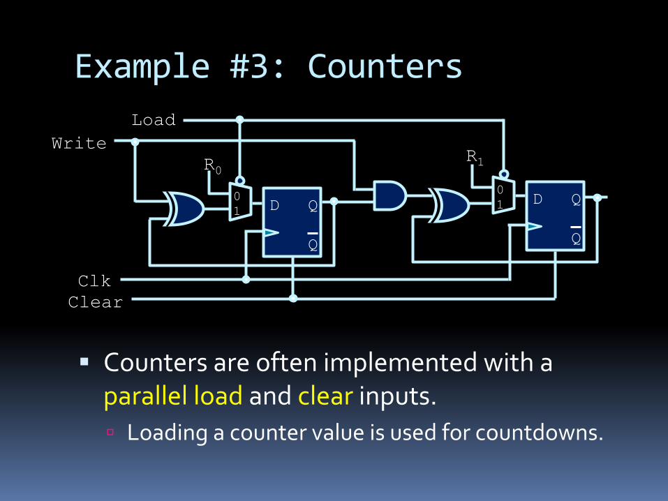
Example#3:Counters
§ Countersareoftenimplementedwithaparallelloadandclearinputs.ú Loadingacountervalueisusedforcountdowns.
D Q
Q
D Q
Q
Clk
R0 R1
0 1
0 1
Load Write
Clear

StateMachines
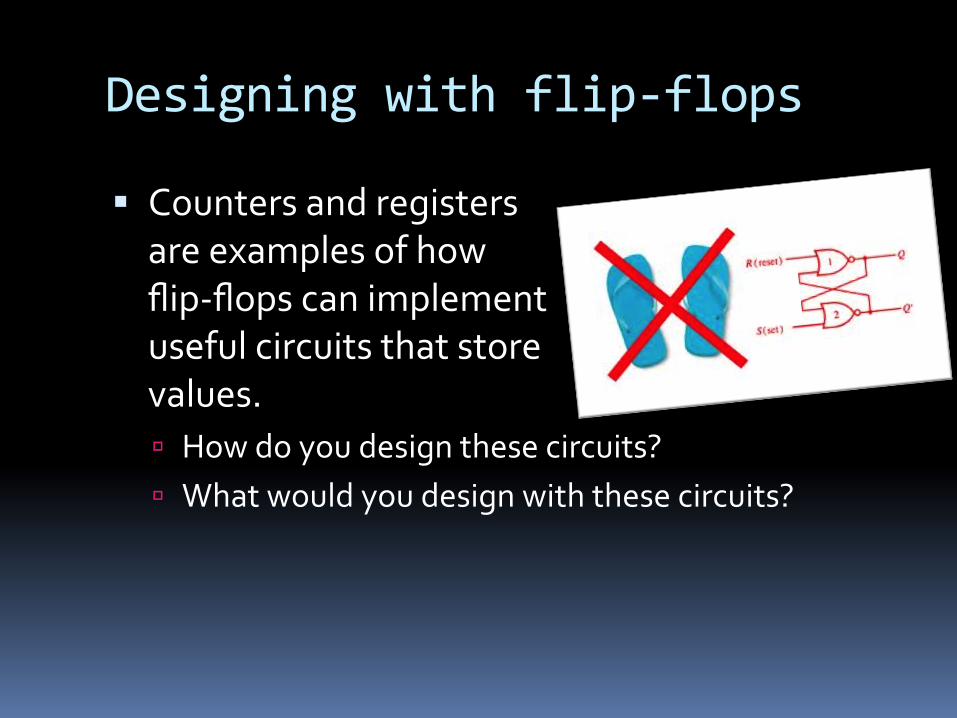
Designingwithflip-flops
§ Countersandregisters areexamplesofhow flip-flopscanimplement usefulcircuitsthatstore values.ú Howdoyoudesignthesecircuits?ú Whatwouldyoudesignwiththesecircuits?

Designingwithflip-flops
§ Sequentialcircuitsarethebasisformemory,instructionprocessing,andanyotheroperationthatrequiresthecircuittorememberpastdatavalues.
§ Thesepastdatavaluesarealsocalledthestatesofthecircuit.
§ Sequentialcircuitsusecombinationallogictodeterminewhatthenextstateofthesystemshouldbe,basedonthepaststateandthecurrentinputvalues.

Stateexample:Counters
§ Withcounters,eachstateisthecurrentnumberthatisstoredinthecounter.
§ Oneachclocktick,thecircuittransitionsfromonestatetothenext,basedontheinputs.
000
001 010 011
100
111 110 101
0
1 1 1
1
1
1 1
1
0 0 0
0
0 0 0
zero
one two three
four
seven six five

StateTables§ Statetableshelptoillustratehowthestatesofthecircuitchangewithvariousinputvalues.ú Transitionsareunderstoodtotakeplaceontheclockticks.
State Write State zero 0 zero
zero 1 one
one 0 one
one 1 two
two 0 two
two 1 three
three 0 three
three 1 four
four 0 four
four 1 five
five 0 five
five 1 six
six 0 six
six 1 seven
seven 0 seven
seven 1 zero

StateTables§ Sametableasonthepreviousslide,butwiththeactualflip-flopvaluesinsteadofstatelabels.§ Note:Flip-flop
valuesarebothinputsandoutputsofthecircuithere.
F1 F2 F3 Write F1 F2 F3 0 0 0 0 0 0 0
0 0 0 1 0 0 1
0 0 1 0 0 0 1
0 0 1 1 0 1 0
0 1 0 0 0 1 0
0 1 0 1 0 1 1
0 1 1 0 0 1 1
0 1 1 1 1 0 0
1 0 0 0 1 0 0
1 0 0 1 1 0 1
1 0 1 0 1 0 1
1 0 1 1 1 1 0
1 1 0 0 1 1 0
1 1 0 1 1 1 1
1 1 1 0 1 1 1
1 1 1 1 0 0 0

Break

FiniteStateMachinesandthisbringsusto…

Asseeninothercourses…
§ Youmayhaveseenfinitestatemachinesbefore,butinadifferentcontext.ú Usedmainlytodescribethegrammarsofalanguage,ortomodelsequencedata.
§ InCSCB58,finitestatemachinesaremodelsforanactualcircuitdesign.ú Thestatesrepresentinternalstatesofthecircuit,whicharestoredintheflip-flopvalues.

FiniteStateMachines(FSMs)§ Fromtheorycourses…
ú AFiniteStateMachineisanabstractmodelthatcapturestheoperationofasequentialcircuit.
§ AFSMisdefined(ingeneral)as:ú Afinitesetofstates,ú Afinitesetoftransitionsbetweenstates,triggeredbyinputstothestatemachine,
ú Outputvaluesthatareassociatedwitheachstateoreachtransition(dependingonthemachine),
ú Startandendstatesforthestatemachine.

Example#1:TickleMeElmo
§ RememberhowtheTickleMeElmoworks!

Example#1:TickleMeElmo
§ Toyreactsdifferentlyeachtimeitissqueezed:ú Firstsqueezeà“Hahaha…thattickles.”ú Secondsqueezeà“Hahaha…ohboy.”ú Thirdsqueezeà“HAHAHAHA…HAHAHAHA…etc”
§ Questionstoask:ú Whataretheinputs?ú Whatarethestatesofthismachine?ú Howdoyouchangefromonestatetothenext?

Example#1:TickleMeElmo
Neutral
Tickles
OhBoy
GoCrazy
Squeeze
Squeeze
Squeeze
Squeeze

MoreelaborateFSMs
§ UsuallyourFSMhasmorethanoneinput,andwilltriggeratransitionbasedoncertaininputvaluesbutnotothers.
§ Alsomighthaveinputvaluesthatdon’tcauseatransition,butkeepthecircuitinthesamestate(transitioningtoitself).

Example#2:AlarmClock
§ Internalstatedescription:ú Startsinneutralstate,until timersignalgoesoff. Clockmovestoalarmstate.
ú Alarmstatecontinuesuntil: snoozebuttonispushed(movetosnoozestate) alarmisturnedoff(movetoneutralstate) timergoesoffagain(movetoneutralstate)
ú Insnoozestate,clockreturnstoalarmstatewhenthetimersignalgoesoffagain.

Example#3:TrafficLight
Red
Yellow Green
Change=1 Change=1
Change=1
Change=0 Change=0
Change=0
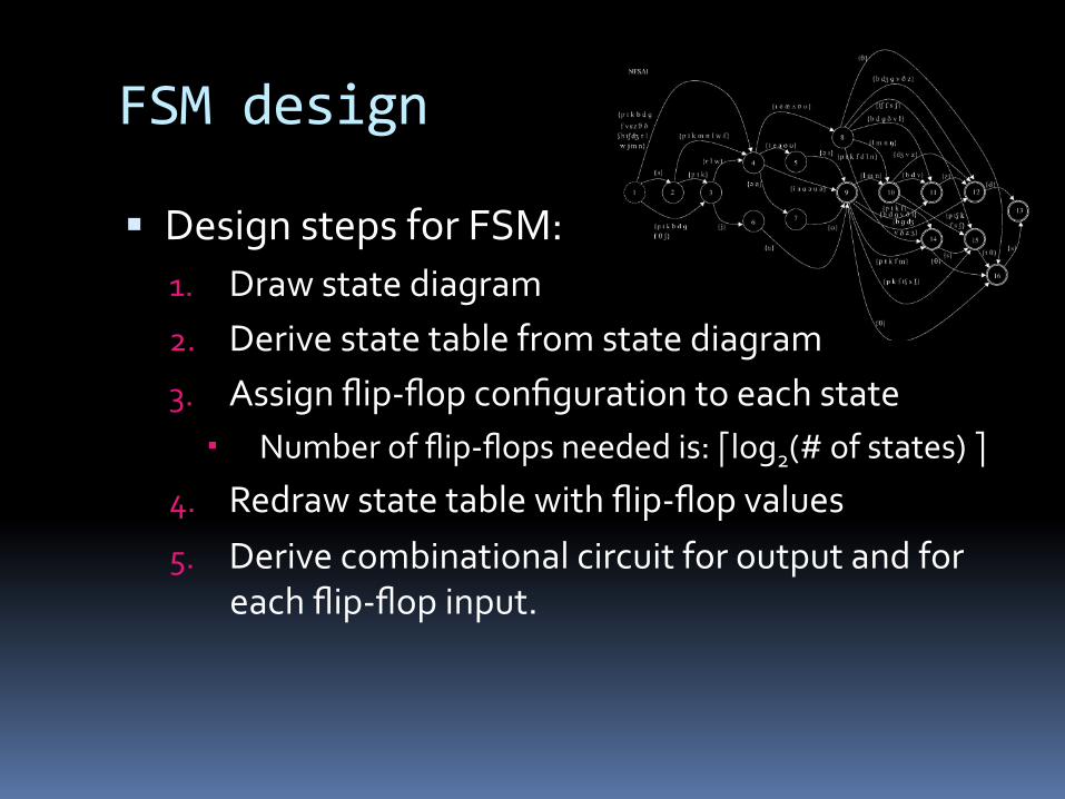
FSMdesign
§ DesignstepsforFSM:1. Drawstatediagram2. Derivestatetablefromstatediagram3. Assignflip-flopconfigurationtoeachstate
Numberofflip-flopsneededis:⎡log2(#ofstates)⎤
4. Redrawstatetablewithflip-flopvalues5. Derivecombinationalcircuitforoutputandfor
eachflip-flopinput.

Example#4:SequenceRecognizer
§ Recognizeasequenceofinputvalues,andraiseasignalifthatinputhasbeenseen.
§ Example:Threehighvaluesinarowú Understoodtomeanthattheinputhasbeenhighforthreerisingclockedges.
ú AssumesasingleinputXandasingleoutputZ.

Step1:Statediagram
§ Inthiscase,thestatesarelabeledwiththeinputvaluesthathavebeenseenuptonow.
§ Transitionsbetweenstatesareindicatedbythevaluesonthetransitionarrows.
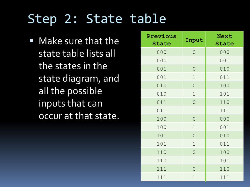
Step2:Statetable§ Makesurethatthestatetablelistsallthestatesinthestatediagram,andallthepossibleinputsthatcanoccuratthatstate.
Previous State
Input Next State
000 0 000
000 1 001
001 0 010
001 1 011
010 0 100
010 1 101
011 0 110
011 1 111
100 0 000
100 1 001
101 0 010
101 1 011
110 0 100
110 1 101
111 0 110
111 1 111

Step3:Assignflip-flops§ Theflip-flopsarethecircuitunitsthatare
responsibleforactuallystoringstates.§ Whendecidinghowmanystatesareneeded,
rememberthatasingleflip-flopcanstoretwovalues(0and1),andthustwostates.
§ Howmanystatescanbestoredwitheachadditionalflip-flop?ú Oneflip-flopà2statesú Twoflip-flopsà4statesú Threeflip-flopsà8statesú …ú Eightflip-flops?à28=256states
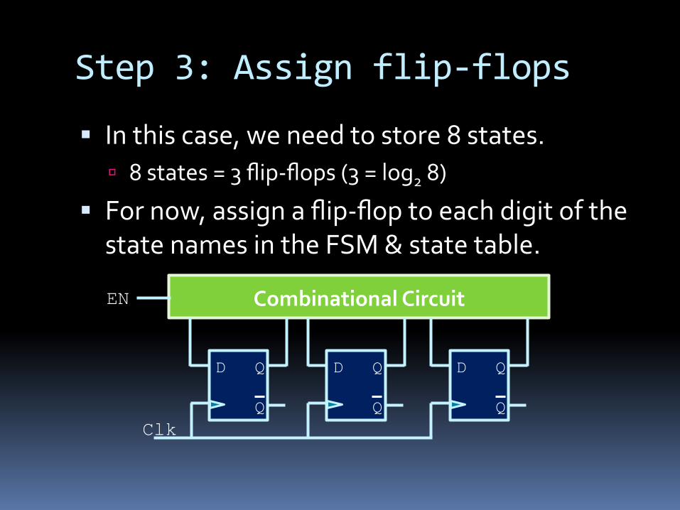
Step3:Assignflip-flops
§ Inthiscase,weneedtostore8states.ú 8states=3flip-flops(3=log28)
§ Fornow,assignaflip-floptoeachdigitofthestatenamesintheFSM&statetable.
D Q
Q
CombinationalCircuit
D Q
Q
D Q
Q Clk
EN
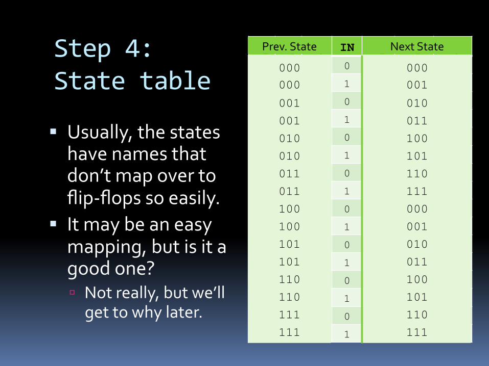
Step4:Statetable
§ Usually,thestateshavenamesthatdon’tmapovertoflip-flopssoeasily.
§ Itmaybeaneasymapping,butisitagoodone?ú Notreally,butwe’llgettowhylater.
F2 F1 F0 IN F2 F1 F0 0 0 0 0 0 0 0
0 0 0 1 0 0 1
0 0 1 0 0 1 0
0 0 1 1 0 1 1
0 1 0 0 1 0 0
0 1 0 1 1 0 1
0 1 1 0 1 1 0
0 1 1 1 1 1 1
1 0 0 0 0 0 0
1 0 0 1 0 0 1
1 0 1 0 0 1 0
1 0 1 1 0 1 1
1 1 0 0 1 0 0
1 1 0 1 1 0 1
1 1 1 0 1 1 0
1 1 1 1 1 1 1
000 000
001
001
010
010
011
011
100
100
101
101
110
110
111
111
Prev.State
000 001
010
011
100
101
110
111
000
001
010
011
100
101
110
111
NextState

Step5:Circuitdesign
§ KarnaughmapforF2(t+1):
F0·IN F0·IN F0·IN F0·IN
F2·F1 0 0 0 0
F2·F1 1 1 1 1
F2·F1 1 1 1 1
F2·F1 0 0 0 0
F2(t+1) = F1(t)

Step5:Circuitdesign
§ KarnaughmapforF1(t+1):
F0·IN F0·IN F0·IN F0·IN
F2·F1 0 0 1 1
F2·F1 0 0 1 1
F2·F1 0 0 1 1
F2·F1 0 0 1 1
F1(t+1) = F0(t)

Step5:Circuitdesign
§ KarnaughmapforF0(t+1):
F0·IN F0·IN F0·IN F0·IN
F2·F1 0 1 1 0
F2·F1 0 1 1 0
F2·F1 0 1 1 0
F2·F1 0 1 1 0
F0(t+1) = EN(t)

Step5:Circuitdesign
§ Resultingcircuitlookslikethediagramontheright.
§ Thiswillrecordthestatesandmakethestatetransitionshappenbasedontheinput,butwhatabouttheoutputvalueZ?ú ZshouldgohighwhenEN
hasbeenhighforthreeclockcyclesinarow.
D Q
Q
D Q
Q
D Q
Q
F0
F1
F2
IN Clk

Step5:Circuitdesign§ BooleanequationforZ:
§ Twowaystoderivethecircuitryneededfortheoutputvaluesofthestatemachine:ú Mooremachine:
TheoutputfortheFSMdependssolelyonthecurrentstate(basedonentryactions).
ú Mealymachine: TheoutputfortheFSMdependsonthestateandtheinput(basedoninputactions).
BeinginstateXcanresultindifferentoutput,dependingontheinputthatcausedthatstate.
Z = F0·F1·F2

FSMdesign
§ DesignstepsforFSM:1. Drawstatediagram2. Derivestatetablefromstatediagram3. Assignflip-flopconfigurationtoeachstate
Numberofflip-flopsneededis:⎡log2(#ofstates)⎤
4. Redrawstatetablewithflip-flopvalues5. Derivecombinationalcircuitforoutputandfor
eachflip-flopinput.

Timingandstateassignments§ Whenassigningstates,youneedtoconsidertheissueoftimingwiththestates.
§ Example:ifrecognizer circuitisinstate011and getsa0asaninput,it movestostate110.ú Thefirstandlastdigits change“atthesametime”
ú Ifthefirstflip-flopchangesfirst,theoutputwouldgohighforaninstant,whichcouldcauseunexpectedbehaviour.

Timingandstateassignments§ Sohowdoyousolvethis?§ Twopossiblesolutions:
1. Wheneverpossible,makeflip-flopassignmentssuchthatneighbouringstatesdifferbyatmostoneflip-flopvalue.
2. Addintermediatetransitionstates

Example#5§ ExplodingPen
ú 3clickstoarmú 3clickstodisarm
§ https://youtu.be/Vi4LmILZU0g
ú Note:Pleasedonotusetheknowledgeyou'vegainedinthiscoursetodevelopexplodingpens.
ú Note2:Ifyoudo,pleasedon'tusethemforevil