A Review on Power Electronics based Compensators in Grid Connected WECS
Upload
rajaraman-kannanCategory
view
325download
18description
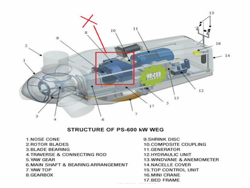
PS 9155 WIND ENERGY CONVERSION SYSTEMS
Bykrr
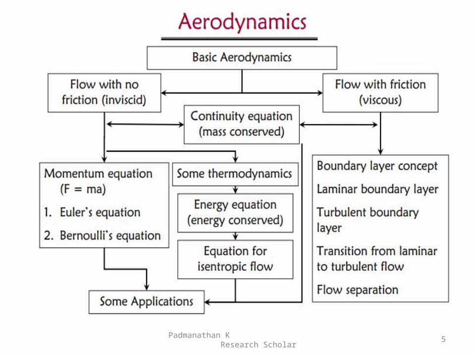
Components of WECS-WECS schemes-Power obtained from wind-simple momentum theory-Power coefficient-Sabinin‟s theory-Aerodynamics of Wind turbine
2
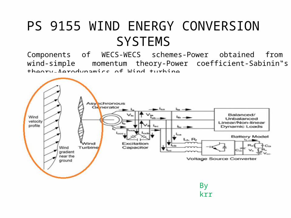
1. simple momentum theory2. Aerodynamics of Wind turbine3. Bernoulli Equation4. Betz Law5. Power coefficient6. Sabinin’s theory
Padmanathan K Research Scholar
3
Padmanathan K Research Scholar
4
Padmanathan K Research Scholar
5
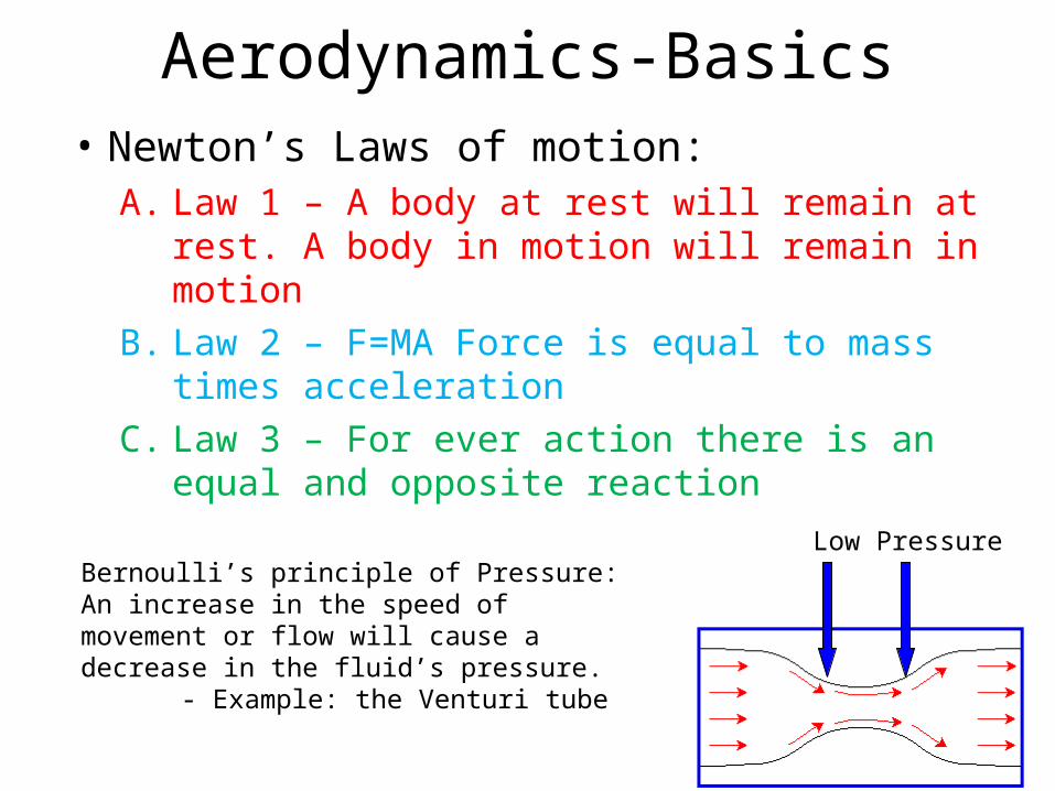
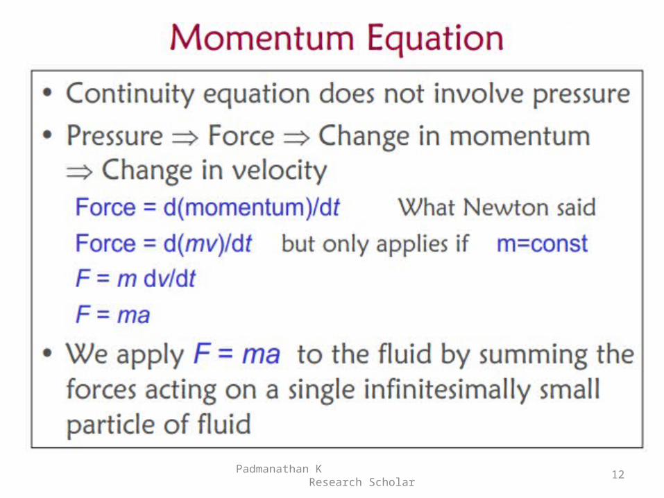
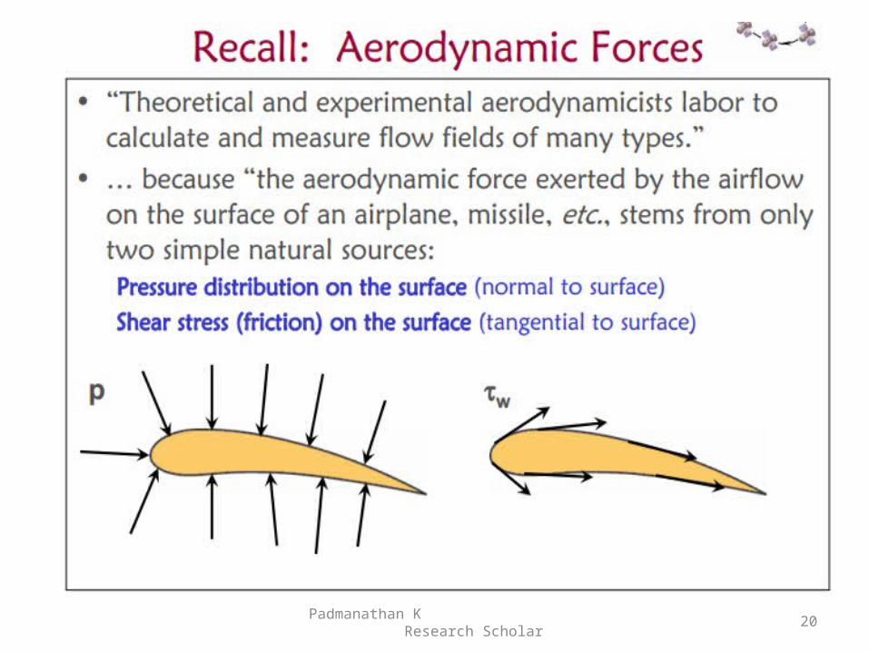
Aerodynamics-Basics• Newton’s Laws of motion:
A. Law 1 – A body at rest will remain at rest. A body in motion will remain in motion
B. Law 2 – F=MA Force is equal to mass times acceleration
C. Law 3 – For ever action there is an equal and opposite reaction
Bernoulli’s principle of Pressure:An increase in the speed of movement or flow will cause a decrease in the fluid’s pressure.
- Example: the Venturi tube
Low Pressure
Padmanathan K Research Scholar
7
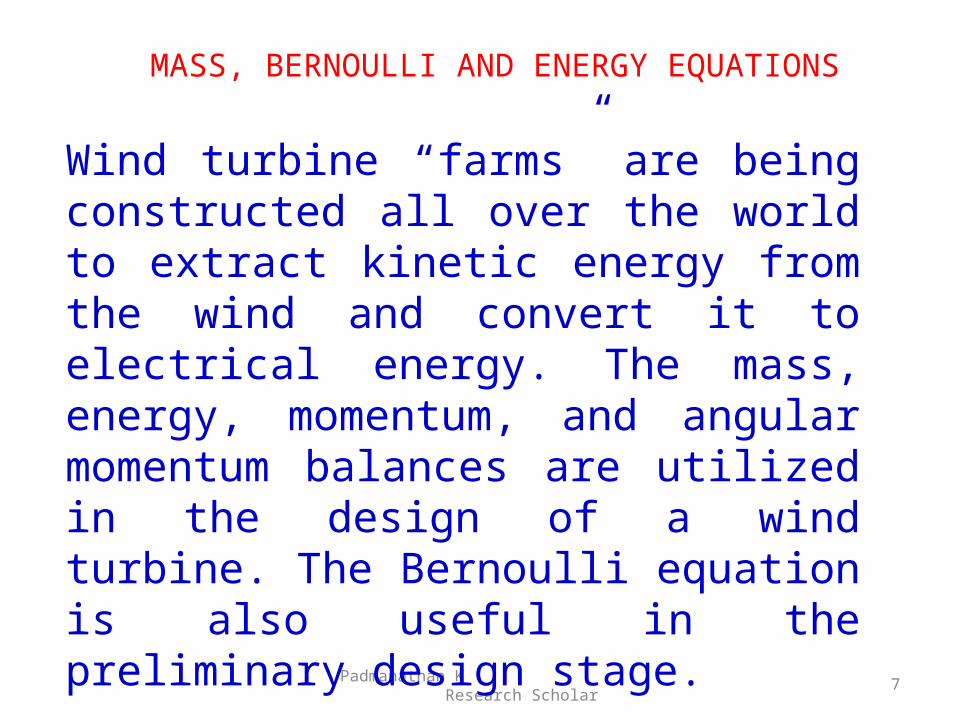
Wind turbine “farms” are being constructed all over the world to extract kinetic energy from the wind and convert it to electrical energy. The mass, energy, momentum, and angular momentum balances are utilized in the design of a wind turbine. The Bernoulli equation is also useful in the preliminary design stage.
MASS, BERNOULLI AND ENERGY EQUATIONS
8
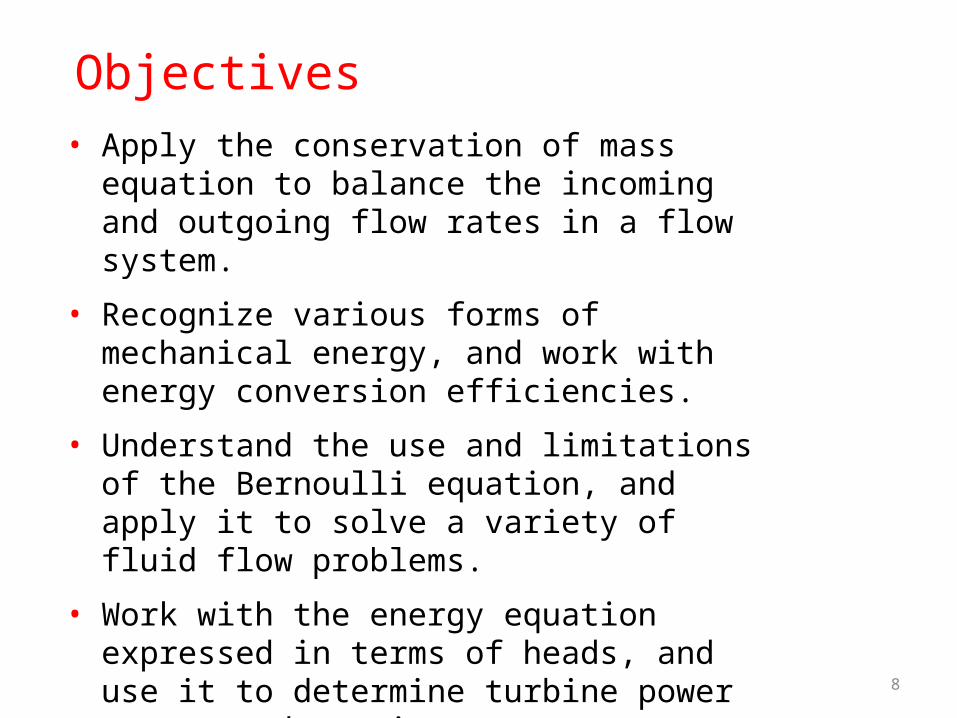
Objectives• Apply the conservation of mass equation to
balance the incoming and outgoing flow rates in a flow system.
• Recognize various forms of mechanical energy, and work with energy conversion efficiencies.
• Understand the use and limitations of the Bernoulli equation, and apply it to solve a variety of fluid flow problems.
• Work with the energy equation expressed in terms of heads, and use it to determine turbine power output and pumping power requirements.
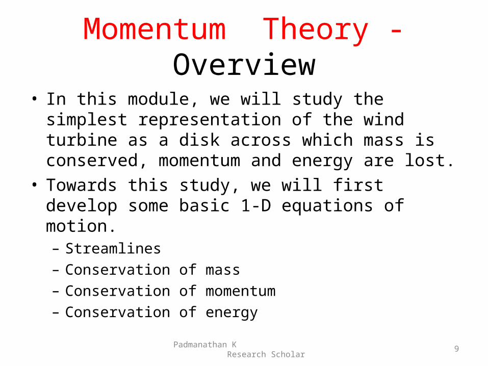
Momentum Theory -Overview
• In this module, we will study the simplest representation of the wind turbine as a disk across which mass is conserved, momentum and energy are lost.
• Towards this study, we will first develop some basic 1-D equations of motion.– Streamlines– Conservation of mass– Conservation of momentum– Conservation of energy
Padmanathan K Research Scholar
9
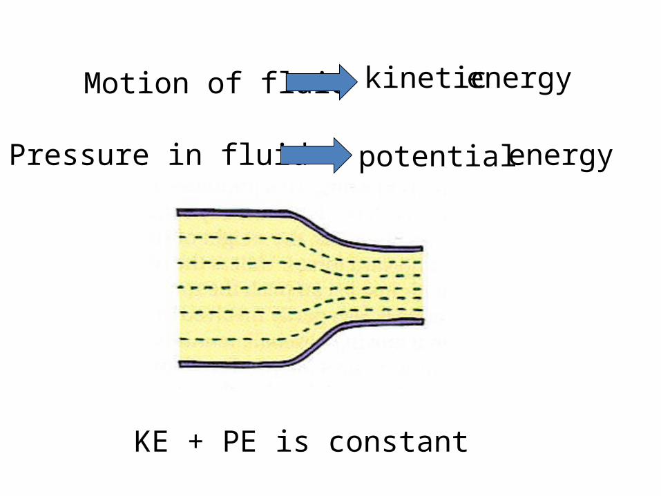
Motion of fluid energykinetic
Pressure in fluid energypotential
KE + PE is constant
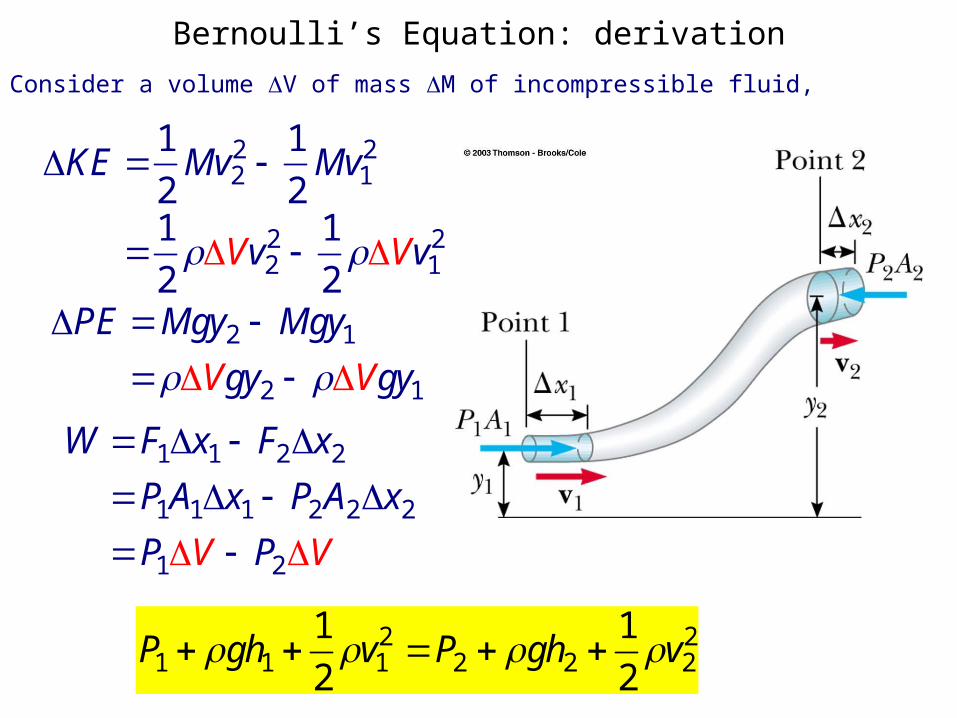
Bernoulli’s Equation: derivationConsider a volume V of mass M of incompressible fluid,
KE 1
2Mv2
2 1
2Mv1
2
1
2Vv2
2 1
2Vv1
2
PE Mgy2 Mgy1Vgy2 Vgy1
W F1x1 F2x2
P1A1x1 P2A2x2
P1V P2V
P1 gh1 1
2v1
2 P2 gh2 1
2v2
2
Padmanathan K Research Scholar
12
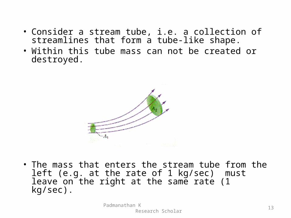
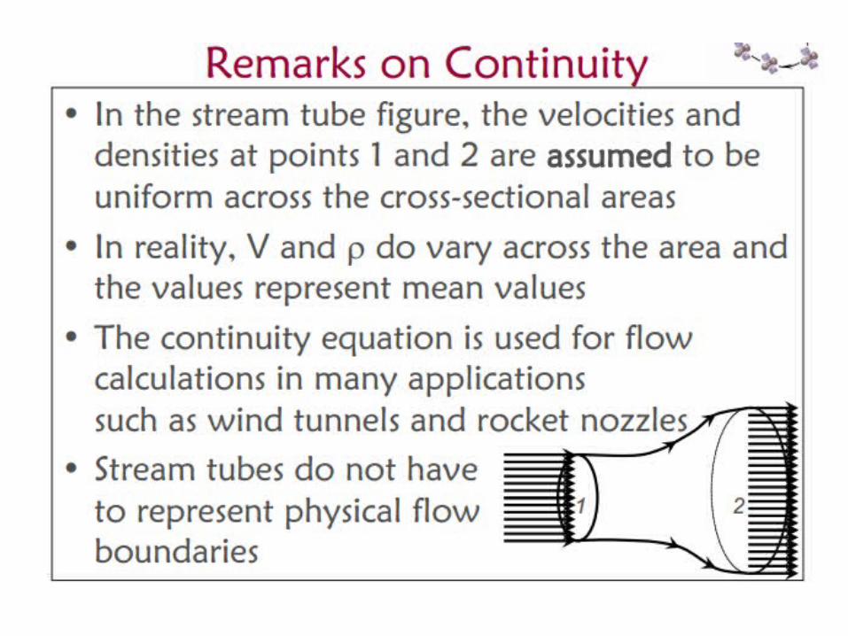
• Consider a stream tube, i.e. a collection of streamlines that form a tube-like shape.
• Within this tube mass can not be created or destroyed.
• The mass that enters the stream tube from the left (e.g. at the rate of 1 kg/sec) must leave on the right at the same rate (1 kg/sec).
Padmanathan K Research Scholar
13
Padmanathan K Research Scholar
14
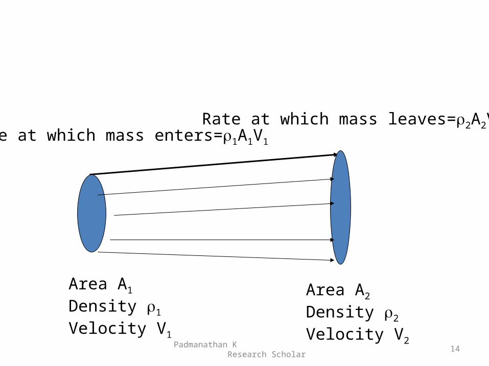
Area A1
Density 1
Velocity V1
Area A2
Density 2
Velocity V2
Rate at which mass enters=1A1V1
Rate at which mass leaves=2A2V2
Padmanathan K Research Scholar
15
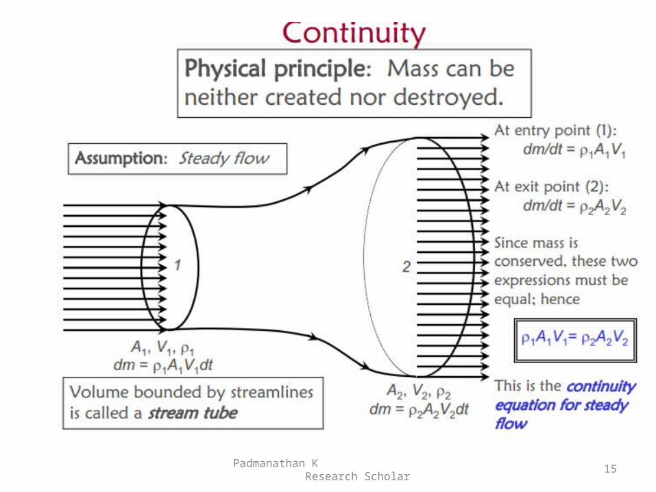
Continuity
Padmanathan K Research Scholar
16
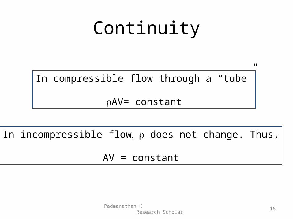
In compressible flow through a “tube”
AV= constant
In incompressible flow does not change. Thus,
AV = constant
Padmanathan K Research Scholar
17
Padmanathan K Research Scholar
18
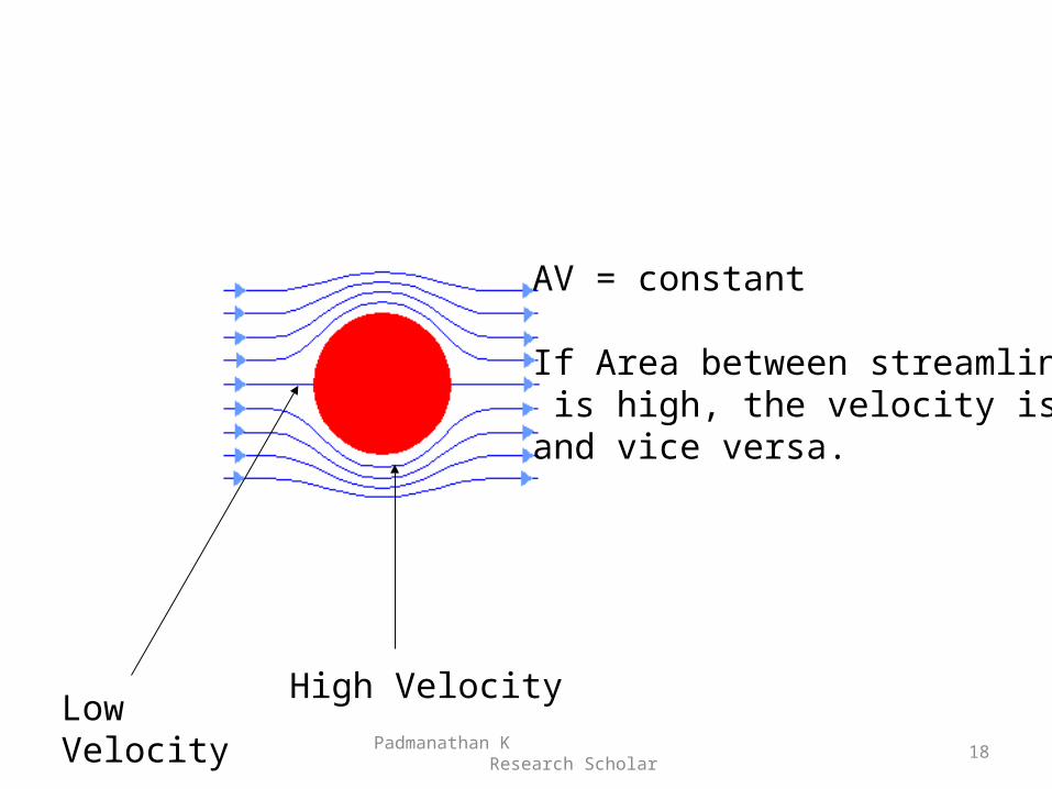
AV = constant
If Area between streamlines is high, the velocity is lowand vice versa.
High VelocityLow Velocity
Padmanathan K Research Scholar
19
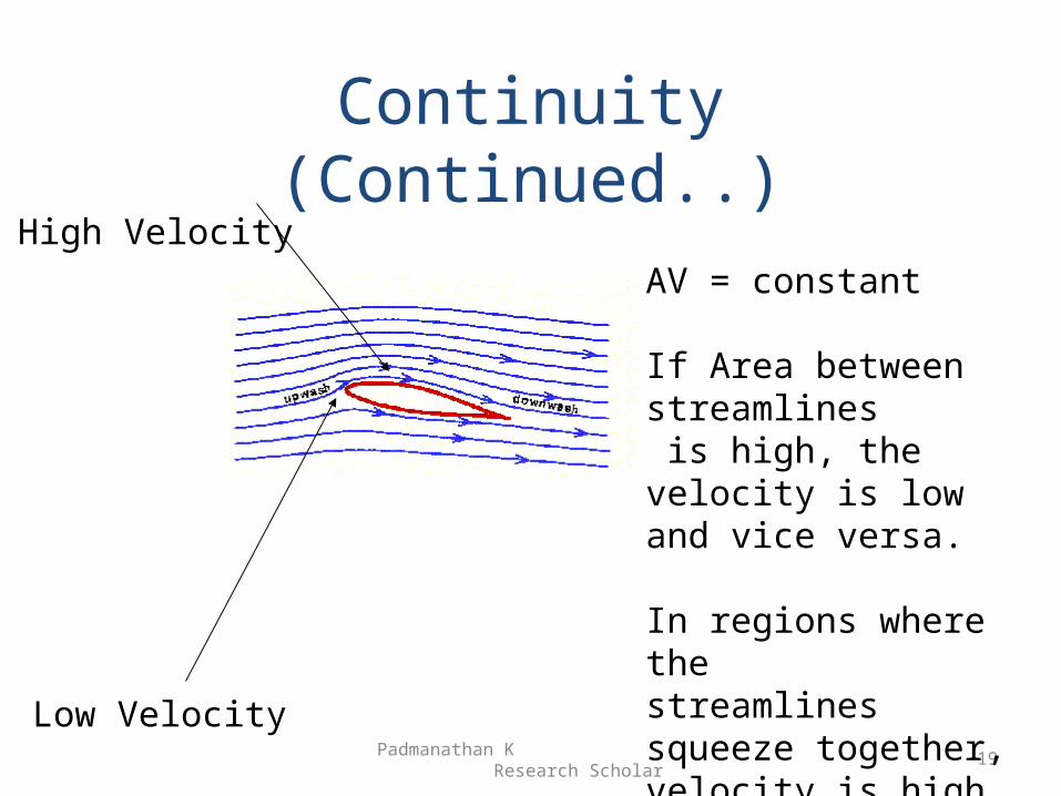
Continuity (Continued..)
AV = constant
If Area between streamlines is high, the velocity is lowand vice versa.
In regions where the streamlines squeeze together,velocity is high.
High Velocity
Low Velocity
Padmanathan K Research Scholar
20
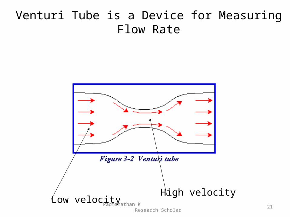
Venturi Tube is a Device for Measuring Flow Rate
Padmanathan K Research Scholar
21Low velocity
High velocity
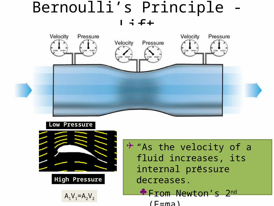
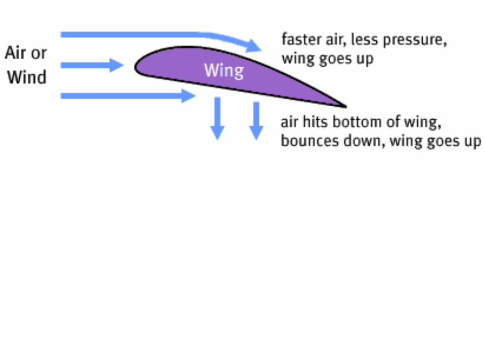
Bernoulli’s Principle - Lift
“As the velocity of a fluid increases, its internal pressure decreases.” From Newton’s 2nd (F=ma) Shown by Venturi tube
Low Pressure
High Pressure
A1V1=A2V2
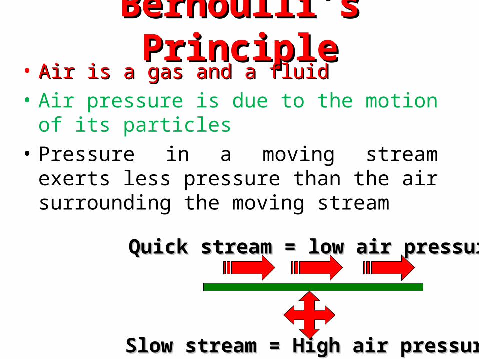
Bernoulli’s PrincipleBernoulli’s Principle• Air is a gas and a fluidAir is a gas and a fluid• Air pressure is due to the motion of its
particles• Pressure in a moving stream exerts less
pressure than the air surrounding the moving stream
Quick stream = low air pressureQuick stream = low air pressure
Slow stream = High air pressureSlow stream = High air pressure
Padmanathan K Research Scholar
24
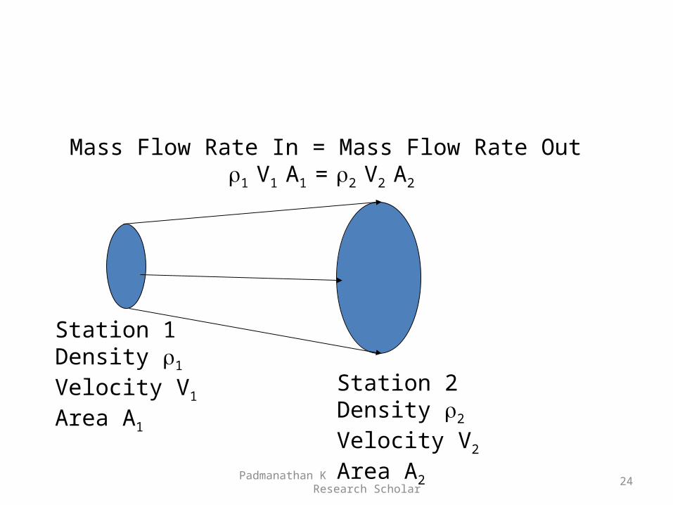
Station 1Density 1
Velocity V1
Area A1
Station 2Density 2
Velocity V2
Area A2
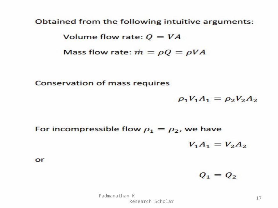
Mass Flow Rate In = Mass Flow Rate Out1 V1 A1 = 2 V2 A2
Padmanathan K Research Scholar
25
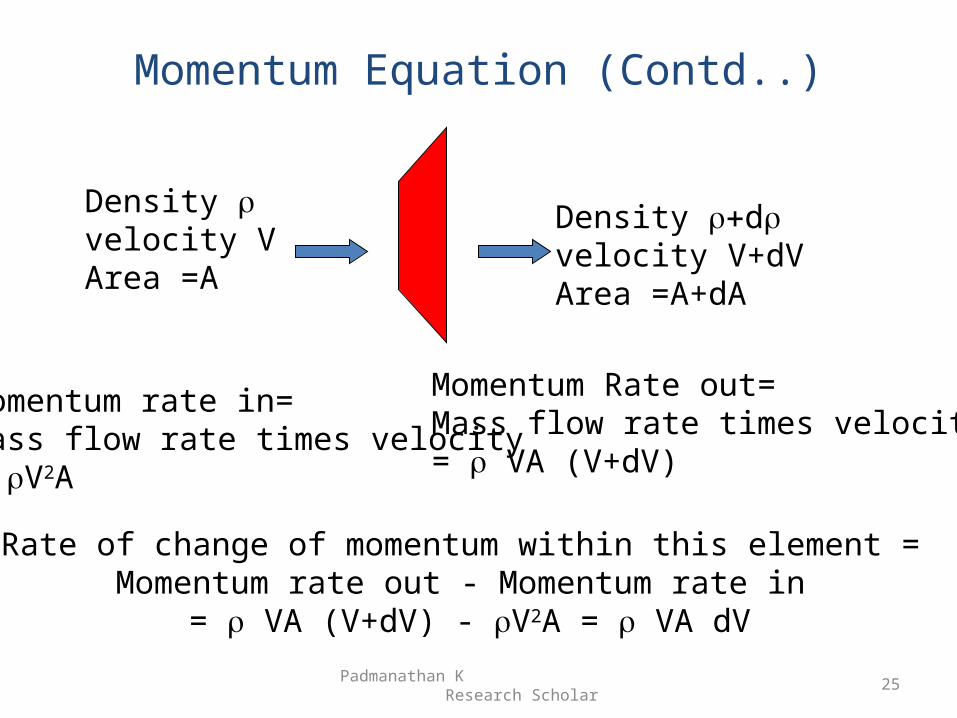
Momentum Equation (Contd..)
Density velocity VArea =A
Density dvelocity V+dVArea =A+dA
Momentum rate in=Mass flow rate times velocity= V2A
Momentum Rate out=Mass flow rate times velocity= VA (V+dV)
Rate of change of momentum within this element = Momentum rate out - Momentum rate in
= VA (V+dV) - V2A = VA dV
Padmanathan K Research Scholar
26
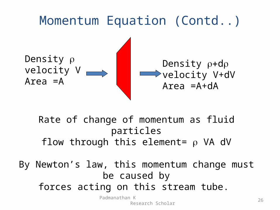
Momentum Equation (Contd..)
Density velocity VArea =A
Density dvelocity V+dVArea =A+dA
Rate of change of momentum as fluid particlesflow through this element= VA dV
By Newton’s law, this momentum change must be caused byforces acting on this stream tube.
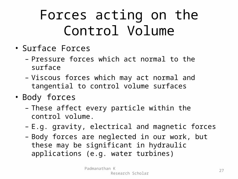
Forces acting on the Control Volume
• Surface Forces– Pressure forces which act normal to the surface– Viscous forces which may act normal and tangential to
control volume surfaces
• Body forces– These affect every particle within the control volume.– E.g. gravity, electrical and magnetic forces– Body forces are neglected in our work, but these may be
significant in hydraulic applications (e.g. water turbines)
Padmanathan K Research Scholar
27
Padmanathan K Research Scholar
28
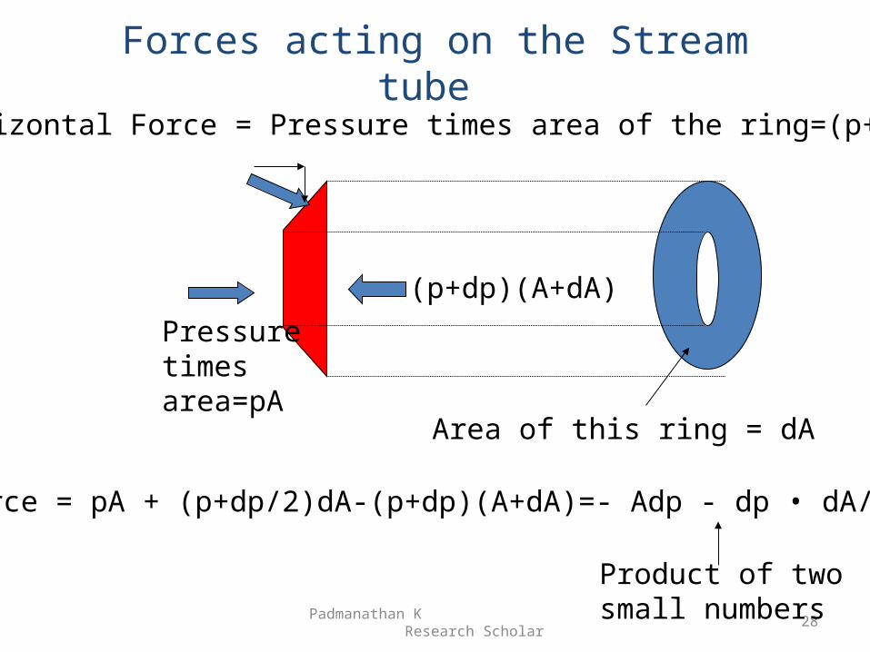
Forces acting on the Stream tube
Pressuretimesarea=pA
(p+dp)(A+dA)
Horizontal Force = Pressure times area of the ring=(p+dp/2)dA
Area of this ring = dA
Net force = pA + (p+dp/2)dA-(p+dp)(A+dA)=- Adp - dp • dA/2-Adp
Product of two small numbers
Momentum Equation
Padmanathan K Research Scholar
29
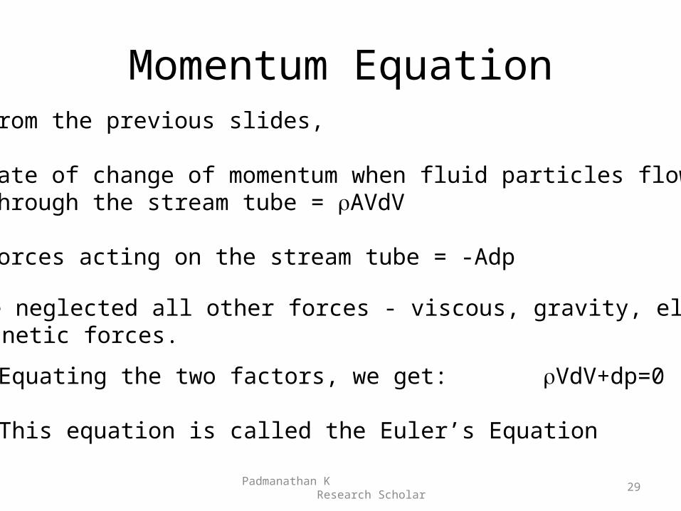
From the previous slides,
Rate of change of momentum when fluid particles flowthrough the stream tube = AVdV
Forces acting on the stream tube = -Adp
We have neglected all other forces - viscous, gravity, electricaland magnetic forces.
Equating the two factors, we get: VdV+dp=0
This equation is called the Euler’s Equation
Bernoulli’s Equation
Padmanathan K Research Scholar
30
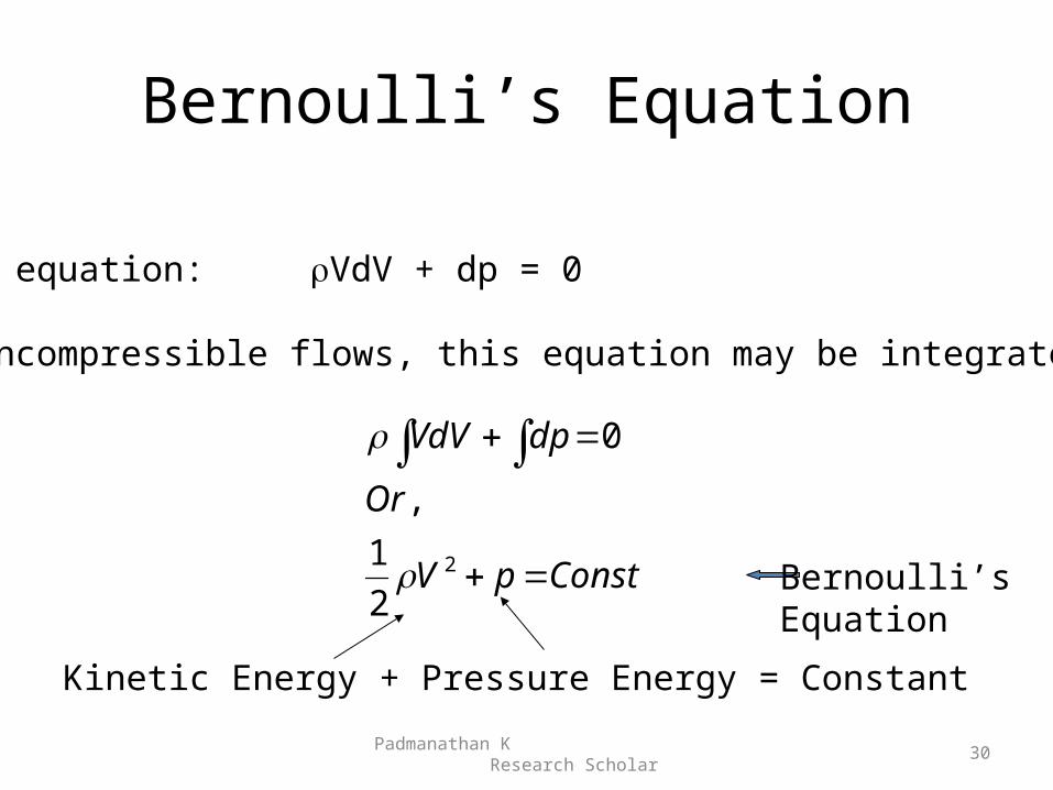
Euler equation: VdV + dp = 0
For incompressible flows, this equation may be integrated:
ConstpV
Or
dpVdV
2
2
1
,
0
Kinetic Energy + Pressure Energy = Constant
Bernoulli’sEquation
Actuator Disk Theory: Background
• Developed for marine propellers by Rankine (1865), Froude (1885).
• Used in propellers by Betz (1920)• This theory can give a first order estimate of HAWT
performance, and the maximum power that can be extracted from a given wind turbine at a given wind speed.
• This theory may also be used with minor changes for helicopter rotors, propellers, etc.
Padmanathan K Research Scholar
31
Assumptions
• Momentum theory concerns itself with the global balance of mass, momentum, and energy.
• It does not concern itself with details of the flow around the blades.
• It gives a good representation of what is happening far away from the rotor.
• This theory makes a number of simplifying assumptions.
Padmanathan K Research Scholar
32
Assumptions (Continued)
• Rotor is modeled as an actuator disk which adds momentum and energy to the flow.
• Flow is incompressible.• Flow is steady, inviscid, irrotational.• Flow is one-dimensional, and uniform through
the rotor disk, and in the far wake.• There is no swirl in the wake.
Padmanathan K Research Scholar
33
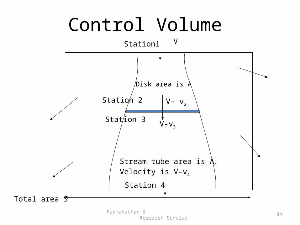
Control Volume
Padmanathan K Research Scholar
34
V
Disk area is A
Total area S
Station1
Station 2
Station 3
Station 4
V- v2
V-v3
Stream tube area is A4
Velocity is V-v4
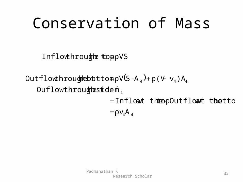
Conservation of Mass
44
1
444
Aρv
bottom at the Outflow topat the Inflow
m side he through tOuflow
)Avρ(VA-SρV bottom he through tOutflow
ρVS tophe through tInflow
Padmanathan K Research Scholar
35
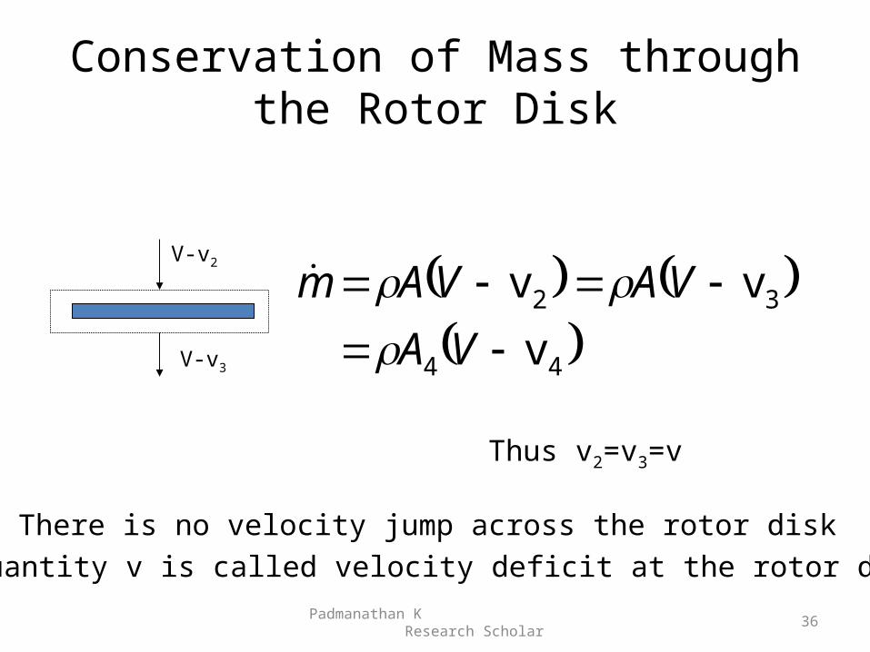
Conservation of Mass through the Rotor Disk
44
32
v
vv
VA
VAVAm
Padmanathan K Research Scholar
36
Thus v2=v3=v
There is no velocity jump across the rotor disk
The quantity v is called velocity deficit at the rotor disk
V-v2
V-v3
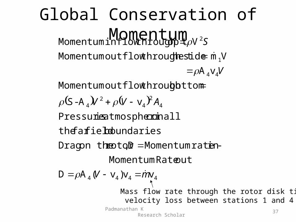
Global Conservation of Momentum
4444
42
42
4
44
1
2
vv)v(A D
out Rate Momentum
-in rate MomentumD,rotor on the Drag
.boundaries fieldfar the
allon catmospheri is Pressure
vA-S
bottom through outflow Momentum
vA
Vm side he through toutflow Momentum
V op through tinflow Momentum
mV
AVV
V
S
Padmanathan K Research Scholar
37
Mass flow rate through the rotor disk times velocity loss between stations 1 and 4
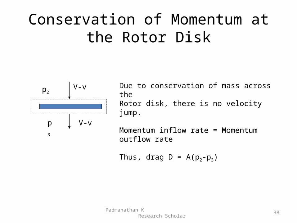
Conservation of Momentum at the Rotor Disk
Padmanathan K Research Scholar
38
V-v
V-v
p2
p3
Due to conservation of mass across theRotor disk, there is no velocity jump.
Momentum inflow rate = Momentum outflow rate
Thus, drag D = A(p2-p3)
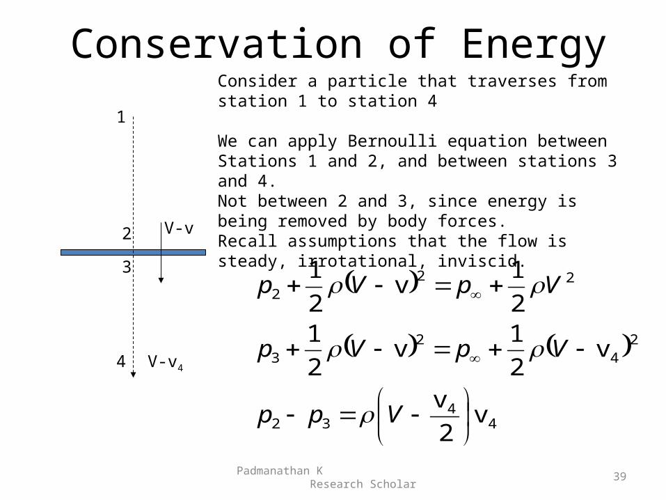
Conservation of Energy
44
32
24
23
222
v2
v
v2
1v
2
12
1v
2
1
Vpp
VpVp
VpVp
Padmanathan K Research Scholar
39
Consider a particle that traverses from station 1 to station 4
We can apply Bernoulli equation betweenStations 1 and 2, and between stations 3 and 4. Not between 2 and 3, since energy is being removed by body forces.Recall assumptions that the flow is steady, irrotational, inviscid.
1
2
3
4
V-v
V-v4
44
32
44
23
v2
v
v2
v
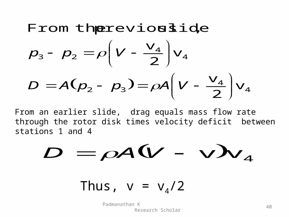
, slide previous theFrom
VAppAD
Vpp
4vv VAD
Padmanathan K Research Scholar
40
From an earlier slide, drag equals mass flow rate through the rotor disk times velocity deficit between stations 1 and 4
Thus, v = v4/2
Induced Velocities
Padmanathan K Research Scholar
41
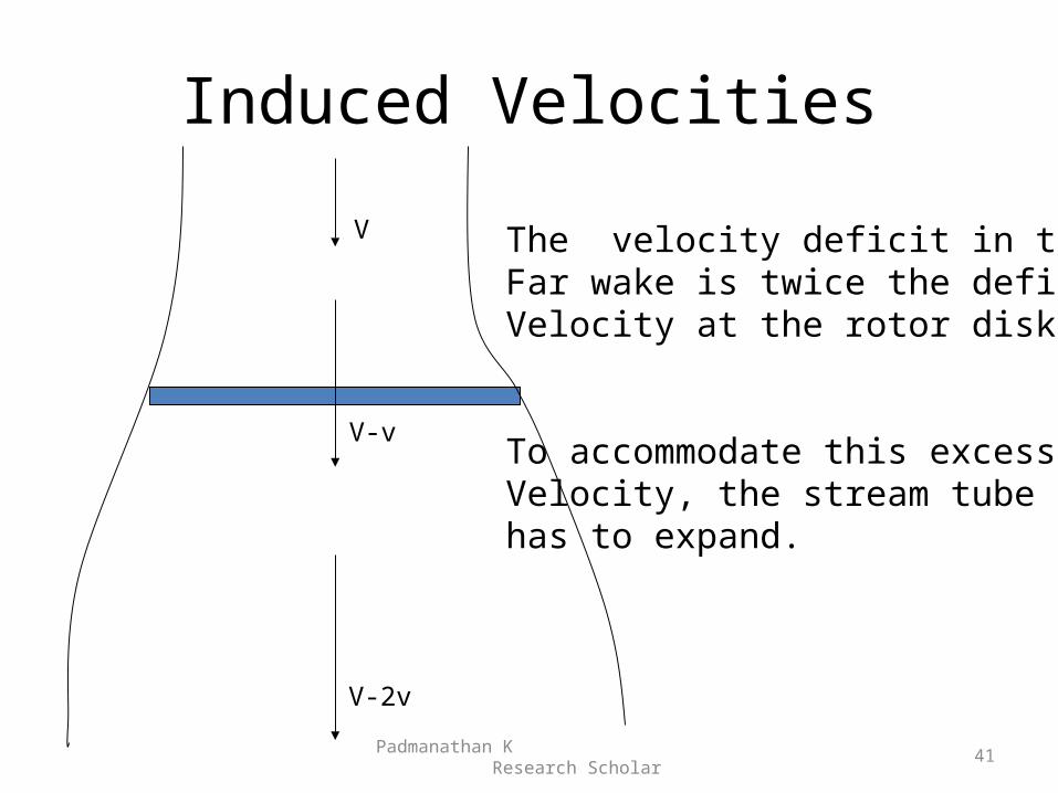
V
V-v
V-2v
The velocity deficit in theFar wake is twice the deficitVelocity at the rotor disk.
To accommodate this excessVelocity, the stream tube has to expand.
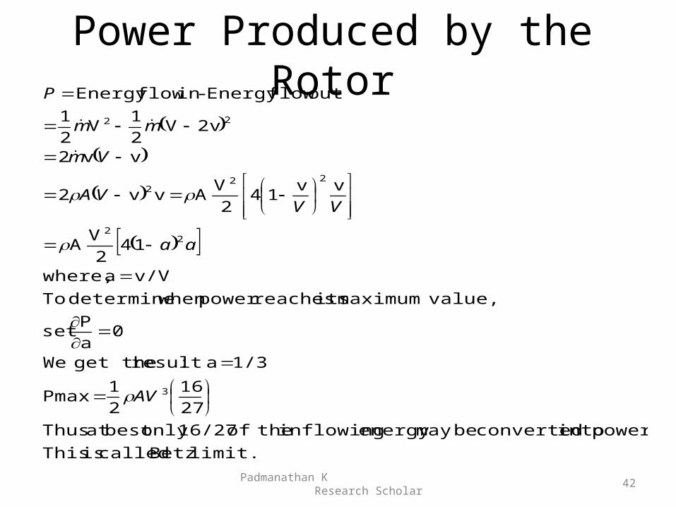
Power Produced by the Rotor
limit. Betz called is This
power. into converted bemay energy inflowing theof 16/27only best at Thus
27
16
2
1 Pmax
1/3 a :result get the We
0a
Pset
value,maximum its reachespower when determine To
v/Va where,
142
VA
vv14
2
VA vv2
vv2
2vV2
1V
2
1
out flowEnergy -in flowEnergy
3
22
222
22
AV
aa
VVVA
Vm
mm
P
Padmanathan K Research Scholar
42
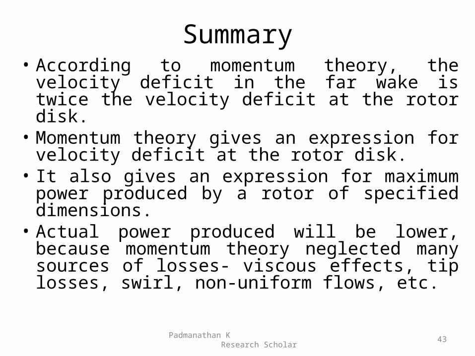
Summary• According to momentum theory, the velocity
deficit in the far wake is twice the velocity deficit at the rotor disk.
• Momentum theory gives an expression for velocity deficit at the rotor disk.
• It also gives an expression for maximum power produced by a rotor of specified dimensions.
• Actual power produced will be lower, because momentum theory neglected many sources of losses- viscous effects, tip losses, swirl, non-uniform flows, etc.
Padmanathan K Research Scholar
43
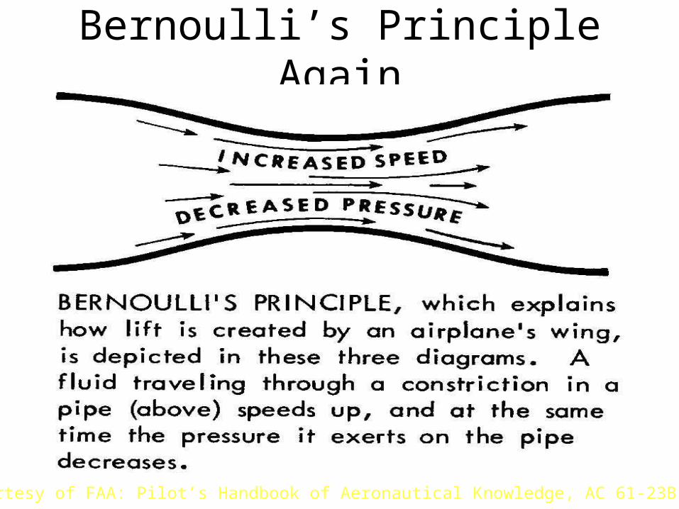
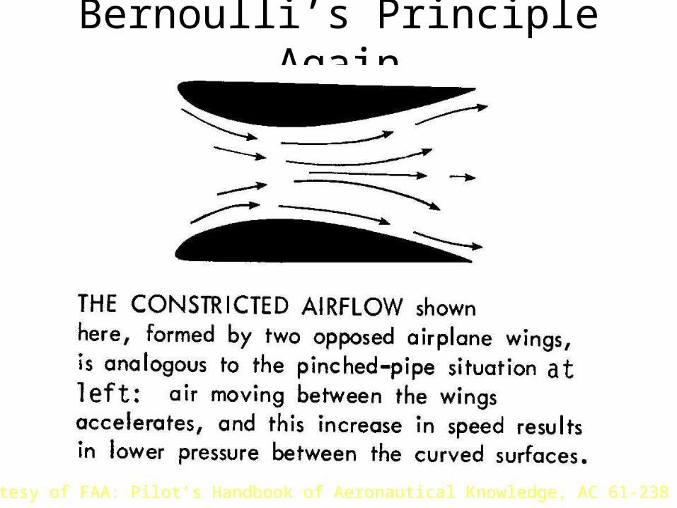
Bernoulli’s Principle Again
Courtesy of FAA: Pilot’s Handbook of Aeronautical Knowledge, AC 61-23B
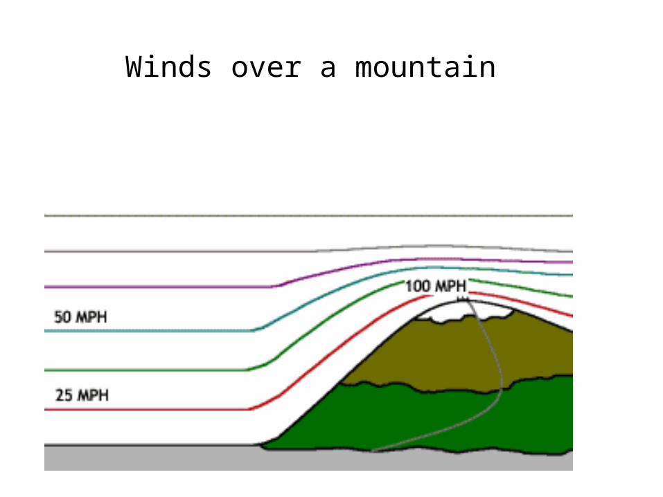
Winds over a mountain
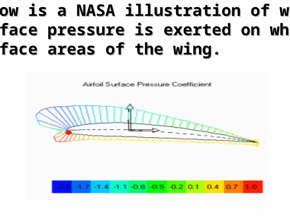
Below is a NASA illustration of whatBelow is a NASA illustration of whatsurface pressure is exerted on what surface pressure is exerted on what surface areas of the wing. surface areas of the wing.
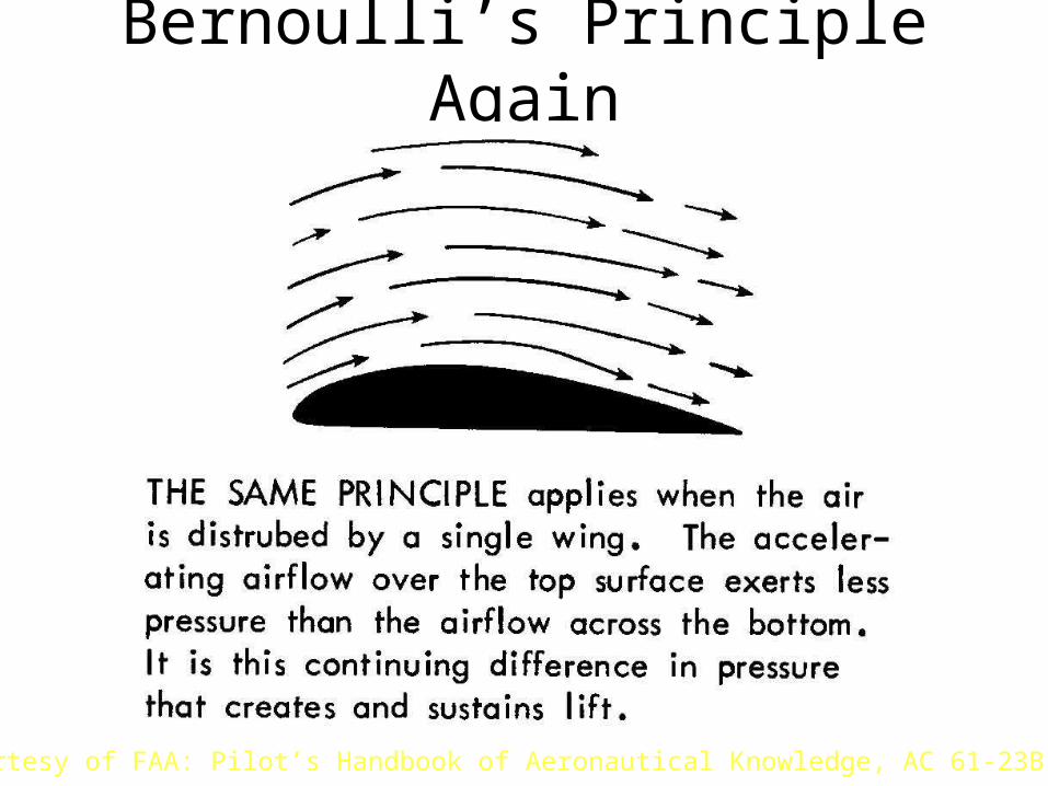
Bernoulli’s Principle Again
Courtesy of FAA: Pilot’s Handbook of Aeronautical Knowledge, AC 61-23B
Bernoulli’s Principle Again
Courtesy of FAA: Pilot’s Handbook of Aeronautical Knowledge, AC 61-23B
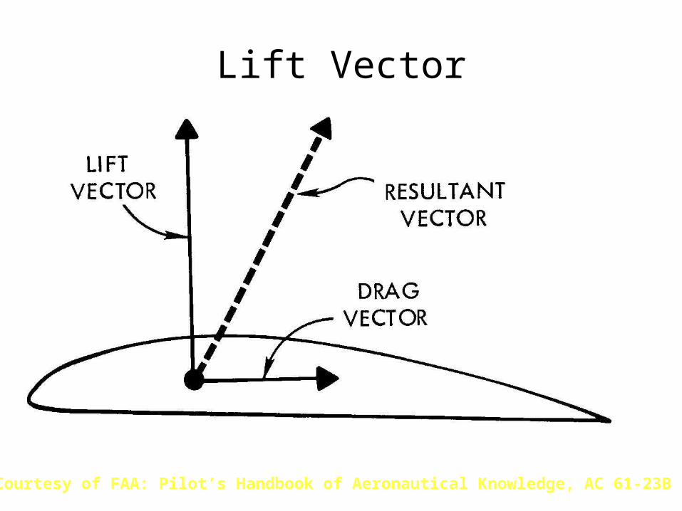
Lift Vector
Courtesy of FAA: Pilot’s Handbook of Aeronautical Knowledge, AC 61-23B
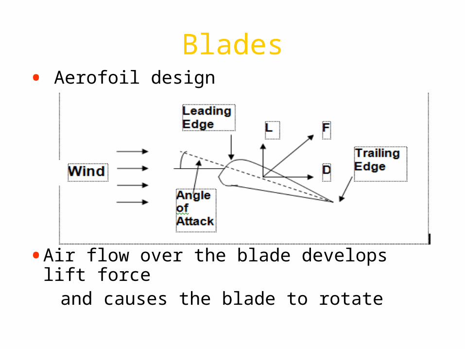
Blades• Aerofoil design
•Air flow over the blade develops lift force and causes the blade to rotate
Drag• Induced drag is a by-product of
lift and is greatly affected by changes of airspeed.
Drag Types Induced drag is the unavoidable by-product of lift and
increases as the angle of attack increasesParasite drag is caused by any aircraft surface that
deflects or interferes with smooth airflow around airplaneSkin-friction drag - between the outer surfaces of
the aircraft and the air through which it moves. Reduced by using glossy, flat finishes on surfaces
Form drag - resistance of air to the shape of the aircraft. Form drag can be reduced by streamlining the aircraft shape.
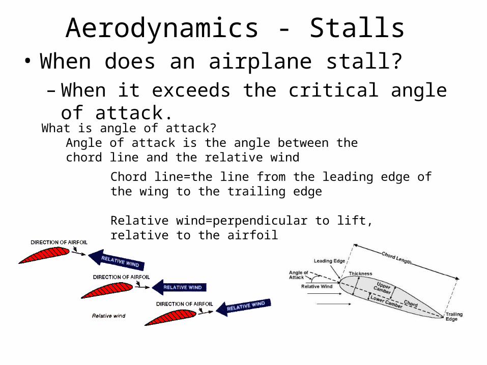
Aerodynamics - Stalls • When does an airplane stall?
– When it exceeds the critical angle of attack.
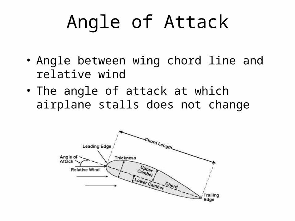
Chord line=the line from the leading edge of the wing to the trailing edge
Relative wind=perpendicular to lift, relative to the airfoil
What is angle of attack?Angle of attack is the angle between the chord line and the relative wind
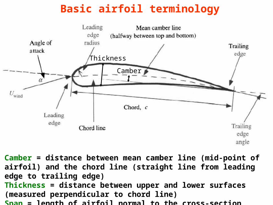
Basic airfoil terminology
Camber = distance between mean camber line (mid-point of airfoil) and the chord line (straight line from leading edge to trailing edge)Thickness = distance between upper and lower surfaces (measured perpendicular to chord line)Span = length of airfoil normal to the cross-section
Camber
Thickness
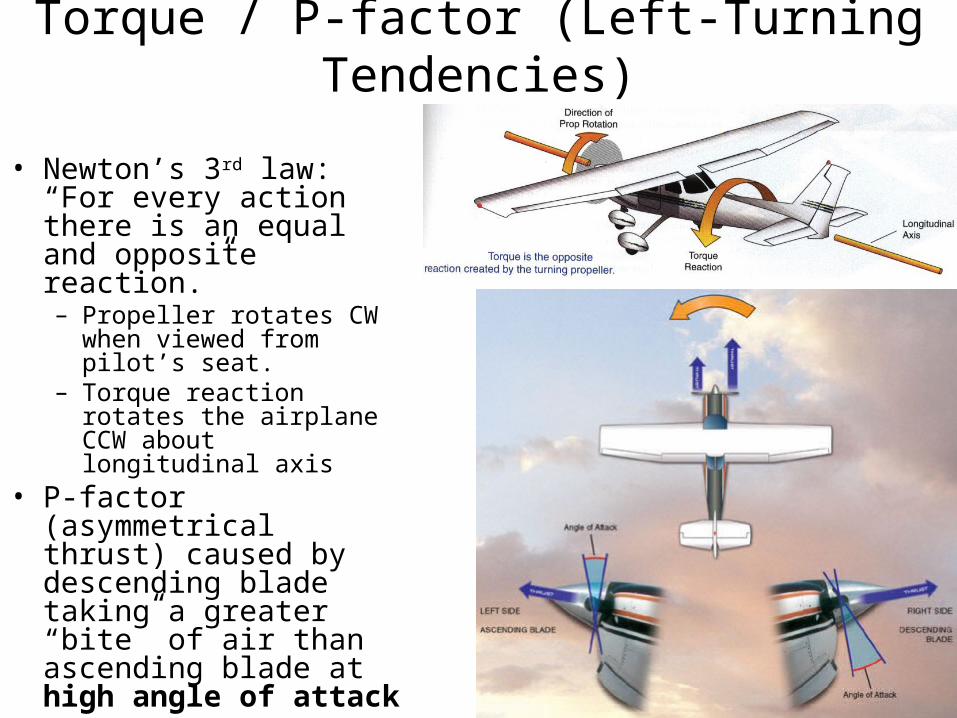
Torque / P-factor (Left-Turning Tendencies)
• Newton’s 3rd law: “For every action there is an equal and opposite reaction.”– Propeller rotates CW when
viewed from pilot’s seat.– Torque reaction rotates the
airplane CCW about longitudinal axis
• P-factor (asymmetrical thrust) caused by descending blade taking a greater “bite” of air than ascending blade at high angle of attack
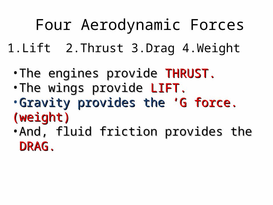
Four Aerodynamic Forces1.Lift 2.Thrust 3.Drag 4.Weight
•The engines provide The engines provide THRUST.THRUST.•The wings provide The wings provide LIFT.LIFT.•Gravity provides the Gravity provides the ‘G force. (weight)‘G force. (weight)•And, fluid friction provides the And, fluid friction provides the DRAG.DRAG.
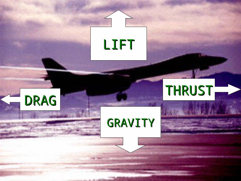
LIFTLIFT
GRAVITYGRAVITY
THRUSTTHRUSTDRAGDRAG
Padmanathan K Research Scholar
60
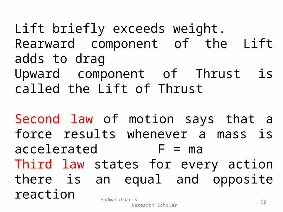
Lift briefly exceeds weight.Rearward component of the Lift adds to dragUpward component of Thrust is called the Lift of Thrust
Second law of motion says that a force results whenever a mass is accelerated F = maThird law states for every action there is an equal and opposite reaction
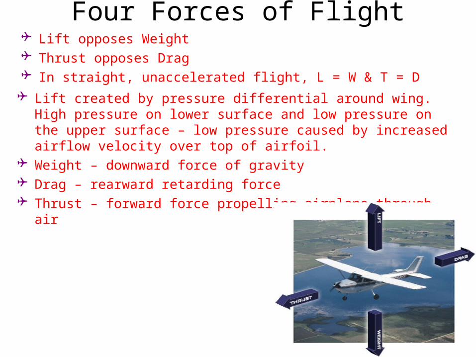
Four Forces of Flight Lift opposes Weight Thrust opposes Drag In straight, unaccelerated flight, L = W & T = D
Lift created by pressure differential around wing. High pressure on lower surface and low pressure on the upper surface – low pressure caused by increased airflow velocity over top of airfoil.
Weight – downward force of gravity Drag – rearward retarding force Thrust – forward force propelling airplane through air
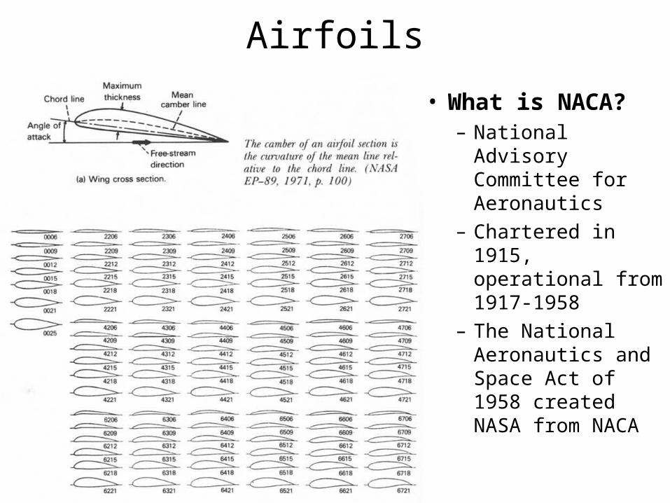
Airfoils
• What is NACA?– National Advisory
Committee for Aeronautics
– Chartered in 1915, operational from 1917-1958
– The National Aeronautics and Space Act of 1958 created NASA from NACA
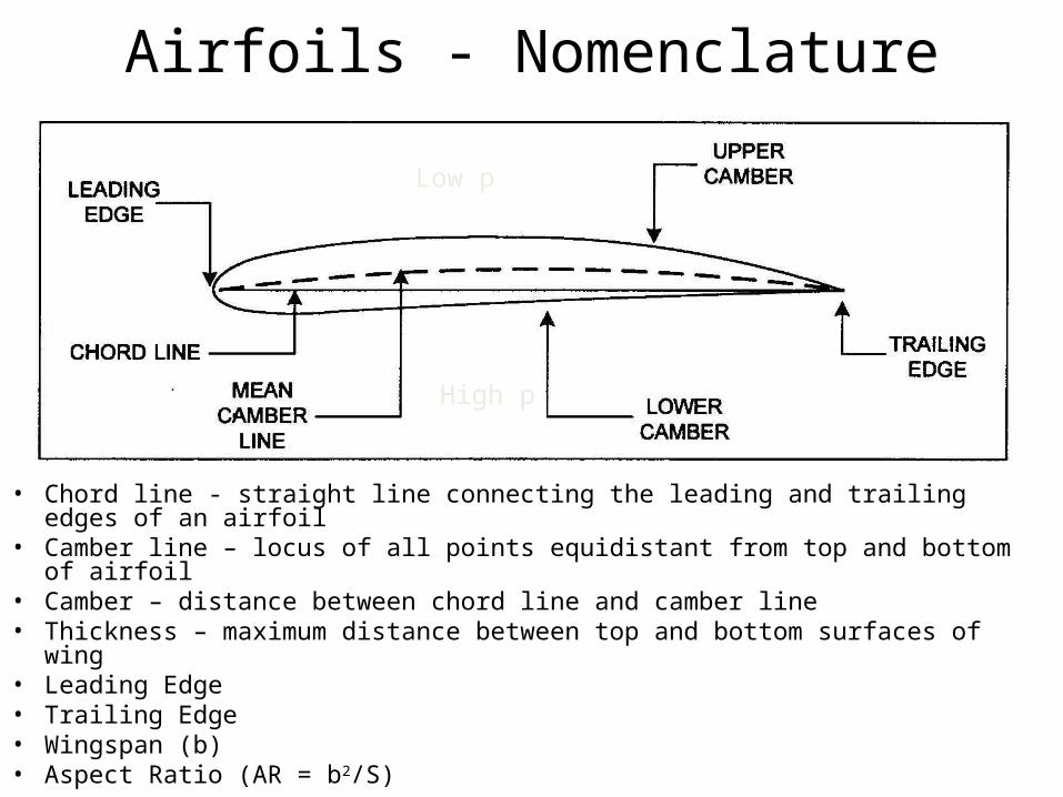
Airfoils - Nomenclature
• Chord line - straight line connecting the leading and trailing edges of an airfoil• Camber line – locus of all points equidistant from top and bottom of airfoil• Camber – distance between chord line and camber line • Thickness – maximum distance between top and bottom surfaces of wing• Leading Edge• Trailing Edge• Wingspan (b)• Aspect Ratio (AR = b2/S)
Low p
High p
Angle of Attack
• Angle between wing chord line and relative wind• The angle of attack at which airplane stalls does
not change
Aerodynamics-Basics
• Because air is a fluid, it utilizes the properties of the Coanda effect: the tendency for a fluid to follow the object along its flow path.
• http://www.youtube.com/watch?v=AvLwqRCbGKY
• http://www.youtube.com/watch?v=S-SAQtODAQw
krr 66
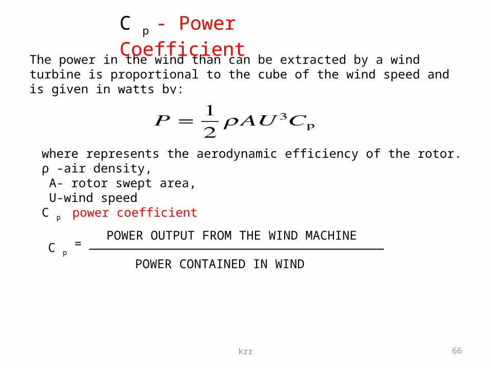
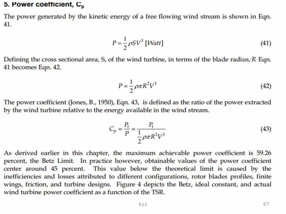
The power in the wind than can be extracted by a wind turbine is proportional to the cube of the wind speed and is given in watts by:
where represents the aerodynamic efficiency of the rotor.ρ -air density, A- rotor swept area, U-wind speed C p power coefficient
C p - Power Coefficient
C p
POWER OUTPUT FROM THE WIND MACHINE
POWER CONTAINED IN WIND
= ________________________________________
krr 67
krr 68
Sabinin’s theoryThe main merit of prof. G.H.Sabinin in wind power for ever remain the presence proved to him so-called « the affixed weight » as a result of which the greatest possible part of energy which can be taken from an ideal rotor makes 68,6 % (instead of 59,3 % on A.Betz). As appeared, almost all world does not know about it and counts aerodynamics of rotors using the formulas A.Betz. A limit of 59,3 % name a limit and even law A.Betz