spacegrant.colorado.eduspacegrant.colorado.edu/COSGC_Projects/space/fall_20… · Web viewBy...
23
Colorado Space Grant Consortium GATEWAY TO SPACE FALL 2012 DESIGN DOCUMENT Team Hang Seven Written by: Lucas Migliorini, Sierra Williams, Chase Goodman, Ethan Hollenbach, Becca Lidvall, Abby Caballero, Paul Smith, Nikhil Desai 10/20/2012 1 7
Transcript of spacegrant.colorado.eduspacegrant.colorado.edu/COSGC_Projects/space/fall_20… · Web viewBy...

Colorado Space Grant Consortium
GATEWAY TO SPACEFALL 2012
DESIGN DOCUMENTTeam Hang Seven
Written by:Lucas Migliorini, Sierra Williams, Chase Goodman, Ethan Hollenbach, Becca Lidvall,
Abby Caballero, Paul Smith, Nikhil Desai10/20/2012Revision C
1
7
Revision Log
Revision
Description Date
A/B Conceptual and Preliminary Design Review 10/20/2012
C Design Document C: Final Design Review 11/16/2012
2
Table of Contents1.0 Mission Overview .............................................................................................................4 1.1 Mission Statement..............................................................................................................41.2 Mission Background..........................................................................................................41.3 Mission Summary..............................................................................................................42.0 Requirements Flow Down ................................................................................................53.0 Design ...............................................................................................................................63.1 Design Diagrams................................................................................................................63.2 Functional Block Diagram.................................................................................................83.3 Schematic...........................................................................................................................93.4 Final Parts List....................................................................................................................94.0 Management ....................................................................................................................104.1 Team Positions.................................................................................................................104.2 Schedule...........................................................................................................................105.0 Budget .............................................................................................................................126.0 Test Plan and Results ......................................................................................................137.0 Expected Results .............................................................................................................157.1 Graph................................................................................................................................16
3

1.0 Mission Overview
1.1 Mission Statement:The mission for team ‘Hang Seven’ is to design, build, test, and launch a BalloonSat,
outfitted with working Geiger counters, to 30 kilometers. The objective for this mission is to analyze the effectiveness of aircraft materials in shielding our Geiger counters from increasing gamma radiation.
1.2 Mission Background:In any manned mission, within the atmosphere or in space, human safety is of utmost
importance. Safety has always been a priority in aviation. The Federal Aviation Administration has implemented many regulations to preserve and ensure human safety while in flight. Regulations have been passed regarding communications, structure, and passenger restraints. Subsequently, radiation is a main concern due to the prolonged effects of exposure on the human body during aircraft transit. Considering such risks, materials would have to be employed to ensure the safety of any passengers. Consequently, as altitude increases so does exposure to radiation of all kinds (alpha, beta, gamma); on a typical passenger aircraft traveling approximately 12,000 meters, the amount of radiation exposure will be double that on the ground.1 As you increase in altitude, much of the Earth’s natural protective attributes such as cloud cover, atmosphere, and the ozone layer is dissipated. Radiation in itself can be a lethal force, only 35 rad (.35 gray) of absorption will cause serious health effects. Negative health effects include: nausea, vomiting, hair loss, loss of consciousness, cancer, and even death. Such negative health effects could be affecting millions of people who travel in aircraft. Even minimal exposure to radiation may result in damage to the human body. As a result, we have decided to test the effectiveness of aircraft materials, primarily aluminum and carbon fiber, in shielding passengers from gamma radiation.
1.3 Mission SummaryThe materials we have chosen to test are carbon fiber and aluminum, as they are used in
commercial airplanes.2 This data will be compared to the control so we can determine which of the two materials is the most plausible solution as a radiation deterrent. Radiation increase with altitude proposes potential health risks once a certain exposure level is reached. By comparing the gamma readings from the control sensor with the increase in altitude of the payload, we can determine this limit. From there we can test the effectiveness of the protective materials to see if they are a viable solution as a defense against human radiation exposure during flight.
1 "Appendix C/Materials Used in Aircraft." Federal Aviation AdministrationFire Safety. Federal Aviation Administration, n.d. Web. 28 Sept. 2012.
<http://www.fire.tc.faa.gov/pdf/handbook/00-12_apC.pdf>.2 "Radiation Hazard at Aircraft Altitudes." Radiation Hazard at Aircraft Altitudes.N.p., n.d. Web. 28 Sept. 2012. <http://www.swpc.noaa.gov/info/RadHaz.html>.
4
Chris Koehler, 11/28/12,
Good enough but can you make this even better for the final report? Any graphics you can use in support of your text? Can you expand your text a bit too.
Chris Koehler, 11/28/12,
List all references at the end. If this is supposed to be a footer citation, that is fine but please use the header/footer in word instead of making your own.
Chris Koehler, 11/28/12,
You never really went into our experiments, like how many Geiger counters and what they are surrounded by and testing. Other than that, this is a good overview section that details the why behind your experiments.
Chris Koehler, 11/28/12,
Physical numbers/data would be great here. What is a harmful level of radiation? How are you going to determine the limit? What exactly is the limit you are determining?
Chris Koehler, 11/28/12,
Write all technical papers in third person. No I, me, you, us, we!
Chris Koehler, 11/28/12,
Are
Chris Koehler, 11/28/12,
Nice background section. Makes the reader understand the motivation behind your expereiments.
Chris Koehler, 11/28/12,
Fantastic. Best mission statement I have seen

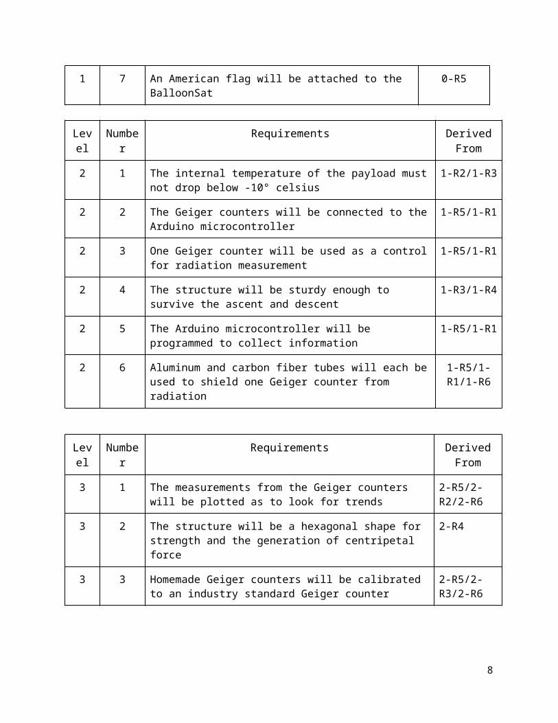
2.0 Requirements Flow DownThe requirements for the Aether mission are presented below. The requirements are an
overview of what needs to be accomplished by our satellite. The level zero requirements are all derived from the mission statement. All subsequent requirements are either derived from the mission statement or the previous requirements.
Level
Number Requirements Derived From
0 1 Payload must ascend to an altitude of 30 kilometers via balloon
Mission Statement
0 2 Payload must store and collect data from our sensors Mission Statement
0 3 The payload mass must not exceed 1.025kg Mission Statement
0 4 The payload must be ready for launch by 1 December, 2012
Mission Statement
0 5 The team and project must obey all safety precautions Mission Statement
Level Number
Requirements Derived From
1 1 The payload must be able to hold all electronics and sensors 0-R2/0-R3
1 2 The payload must contain a heater 0-R2/0-R3
1 3 The payload must contain a power source 0-R2/0-R3
1 4 The payload must be constructed solely of foam core 0-R1/0-R3
1 5 The payload must contain three working geiger counters 0-R2/0-R3
1 6 Geiger counters will be shielded with different materials 0-R2/0-R3
1 7 An American flag will be attached to the BalloonSat 0-R5
Level
Number Requirements Derived From
2 1 The internal temperature of the payload must not drop below -10° celsius
1-R2/1-R3
2 2 The Geiger counters will be connected to the Arduino 1-R5/1-R1
5
Chris Koehler, 11/28/12,
This is not really a requirement from the mission statement. 2 #1 is the real requirement that drives the need for a heater.
Chris Koehler, 11/28/12,
Shall is better than must in requirements.
Chris Koehler, 11/28/12,
What is this? First time mentioned.
Chris Koehler, 11/28/12,
Better but still needs some work. Really only need Level 0 and Level 1 requirements. Some of your levels are mixed up in my opinion. See one example below.

microcontroller
2 3 One Geiger counter will be used as a control for radiation measurement
1-R5/1-R1
2 4 The structure will be sturdy enough to survive the ascent and descent
1-R3/1-R4
2 5 The Arduino microcontroller will be programmed to collect information
1-R5/1-R1
2 6 Aluminum and carbon fiber tubes will each be used to shield one Geiger counter from radiation
1-R5/1-R1/1-R6
Level
Number Requirements Derived From
3 1 The measurements from the Geiger counters will be plotted as to look for trends
2-R5/2-R2/2-R6
3 2 The structure will be a hexagonal shape for strength and the generation of centripetal force
2-R4
3 3 Homemade Geiger counters will be calibrated to an industry standard Geiger counter
2-R5/2-R3/2-R6
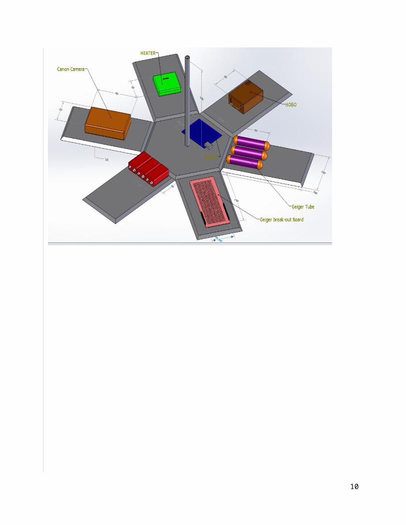
3.0 DesignAether shall be made with foam core, in a hexagonal shape, in accordance with the diagram.
This shape was chosen due to the centripetal force that will keep the Balloon Sat equipment on the side of the satellite as it hurtles towards the earth. The design will protect the equipment from the whip effect as well, when the burst of the balloon will cause a swinging effect on Aether and the other payloads. Team Hang Seven will attach the listed components, and the wires connecting them, to the insides of the structure with Velcro. All parts of the satellites will be subjected to testing and modification accordance to the results of those tests.
The satellite shall be measuring gamma radiation, and will therefore have three Geiger counters along with the power and recording equipment for this test. We will make the Geiger counters ourselves by following a schematic (below) that uses disposable camera flash units and Geiger tube obtained online.3 One Geiger tube will be not covered by any material, another will be covered with an aluminum tube, and the last will be within a carbon fiber casing. This will allow us to determine which, if any, material blocks radiation the best. The Geiger counters will be connected to an Arduino board which will collect and store the data. Following the block diagram, the counters will be connected to one switch but each will have its own batteries for the power source.
3.1 Design Diagrams:
6
Chris Koehler, 11/28/12,
Discussion on how requirements are being met with current design?
Chris Koehler, 11/28/12,
It seems that some of your details of the design are missing. I would like to see much more detail on your design put back into this section.

The design diagrams are found in the following pages.
7
Chris Koehler, 11/28/12,
Nice picture but dimensions are unreadable.
Chris Koehler, 11/28/12,
Show units for your diagrams and make sure the dimensions are readable.
___________________________________________________________________________________3"Step by Step Hacking a Disposable Camera Flash Unit to Power a Geiger Tube." « Mad ScientistHut Blog. N.p., n.d. Web. 21 Oct. 2012.<http://madscientisthut.com/wordpress/daily-blog/hacking-a-disposable-camera-flash-unit-to-power-a-geiger-tube/>.___________________________________________________________________________________
3.2 Functional Block Diagram:
8

3.3 Schematic:
9
Chris Koehler, 11/28/12,
Of what? I know it’s your Geiger counter but any other reader does not see a label. Hand-sketches are fine but make sure they are legible and neatly drawn. I would also suggest you have a paragraph describing your schematic and how it functions.
Chris Koehler, 11/28/12,
Visual indicators?
Chris Koehler, 11/28/12,
Legend for what the colors mean.
3.4: Final Parts List
Resistors Capacitors Diodes Other
47k𝜴 .001𝛍f uf4007 1RF640
22k𝜴 .005𝛍f : 1.4kv uf4007 Transformer
22k𝜴 .005𝛍f : 1.4kv .6V Zener 2N2222
1k𝜴 .01𝛍f 2N2222
4.7k𝜴 LM555
4.3k𝜴1k𝜴2.2k𝜴100k𝜴
4.0 Management The management system for our team is all work will be divided among the team members.
All members of the team will lead/specialize in at least one of the subsystems (The lead position is in black, the assistant position is in white). The assistant position will entail checking and aiding the leads of the subsystem they are assigned to. Our schedule is made up of a few weekly meetings on Monday and Tuesday along with extra meetings for building, testing, and review preparation.
4.1 Team Positions:
10
Chris Koehler, 11/28/12,
Where were the parts ordered, cost, part number?
Chris Koehler, 11/28/12,
What is this for? Is this supposed to be for your whole system? Where did you get these parts? How much? Where are the tubes?

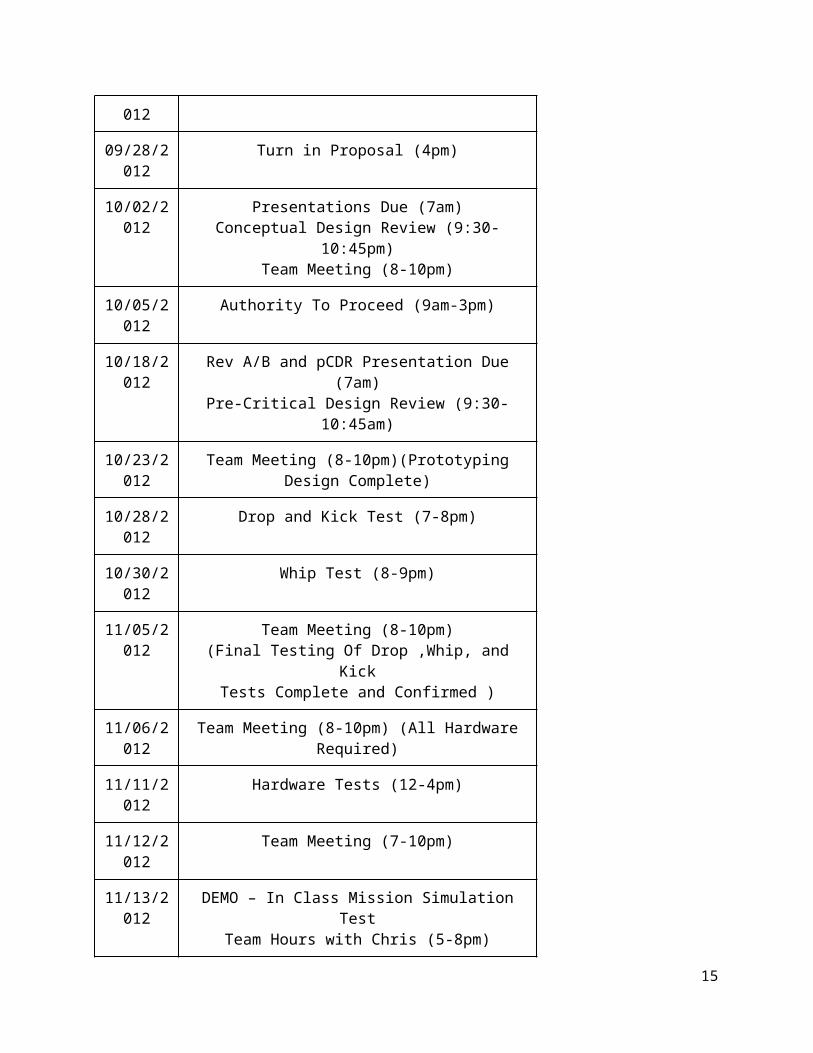
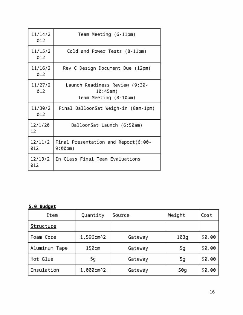
4.2 Schedule:
Date Meeting
09/13/2012
Team Meeting (8-10pm) (Weekly)
09/17/2012
Team Meeting (8-10pm) (Weekly)
09/18/2012
Team Meeting (8-10pm) (Design Complete)
09/24/2012
Create Proposal (8-10pm)
09/27/2012
Review Proposal Meeting (10-12am)
09/28/201 Turn in Proposal (4pm)
11

2
10/02/2012
Presentations Due (7am)Conceptual Design Review (9:30-10:45pm)
Team Meeting (8-10pm)
10/05/2012
Authority To Proceed (9am-3pm)
10/18/2012
Rev A/B and pCDR Presentation Due (7am)Pre-Critical Design Review (9:30-10:45am)
10/23/2012
Team Meeting (8-10pm)(Prototyping Design Complete)
10/28/2012
Drop and Kick Test (7-8pm)
10/30/2012
Whip Test (8-9pm)
11/05/2012
Team Meeting (8-10pm)(Final Testing Of Drop ,Whip, and Kick
Tests Complete and Confirmed )
11/06/2012
Team Meeting (8-10pm) (All Hardware Required)
11/11/2012
Hardware Tests (12-4pm)
11/12/2012
Team Meeting (7-10pm)
11/13/2012
DEMO – In Class Mission Simulation TestTeam Hours with Chris (5-8pm)
11/14/2012
Team Meeting (6-11pm)
11/15/2012
Cold and Power Tests (8-11pm)
11/16/2012
Rev C Design Document Due (12pm)
11/27/2012
Launch Readiness Review (9:30-10:45am)Team Meeting (8-10pm)
11/30/201 Final BalloonSat Weigh-in (8am-1pm)
12

2
12/1/2012 BalloonSat Launch (6:50am)
12/11/2012
Final Presentation and Report(6:00-9:00pm)
12/13/2012
In Class Final Team Evaluations
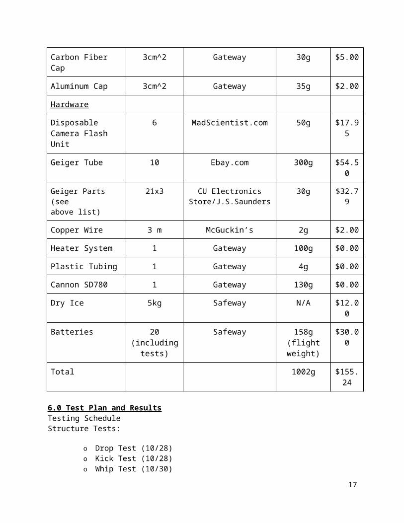
5.0 Budget
Item Quantity Source Weight Cost
Structure
Foam Core 1,596cm^2 Gateway 103g $0.00
Aluminum Tape 150cm Gateway 5g $0.00
Hot Glue 5g Gateway 5g $0.00
Insulation 1,000cm^2 Gateway 50g $0.00
Carbon Fiber Cap
3cm^2 Gateway 30g $5.00
Aluminum Cap 3cm^2 Gateway 35g $2.00
Hardware
Disposable Camera Flash Unit
6 MadScientist.com 50g $17.95
Geiger Tube 10 Ebay.com 300g $54.50
Geiger Parts (see above list)
21x3 CU Electronics Store/J.S.Saunders
30g $32.79
Copper Wire 3 m McGuckin’s 2g $2.00
Heater System 1 Gateway 100g $0.00
Plastic Tubing 1 Gateway 4g $0.00
13

Cannon SD780 1 Gateway 130g $0.00
Dry Ice 5kg Safeway N/A $12.00
Batteries 20 (including tests)
Safeway 158g (flight weight)
$30.00
Total 1002g $155.24
6.0 Test Plan and ResultsTesting ScheduleStructure Tests:
o Drop Test (10/28)o Kick Test (10/28)o Whip Test (10/30)
Hardware Tests:
o Geiger Counter Test Pt. 1 (11/7 & 11/9)o Camera Hardware (11/13)o Arduino Sensors (11/13)o Power (11/15)o Cold (11/15)o Geiger Counter Test Pt. 2 (TBD)
Structure TestsDrop Test: After completing the structure, we tested to see how well our structure would survive landing by dropping it off of multiple buildings. These buildings included the front balcony of the ITLL and the top of the DLC. The drop off the ITLL building ended in failure, our box was unable to handle the impact of landing and broke open. In order to simulate the weight of the hardware we placed rocks inside of it that were approximately the same weight as the components will be for launch. Our structure was holding weight to simulate the hardware that will be inside it. We concluded that our structure was sufficient enough to withstand the impact of landing.
Kick Test: We tested our structure to see how well it would survive a rough landing. To do so, we kicked our structure down a huge flight of stairs in the DLC. The weights were weighed to ensure the correct amount of weight was placed inside our box. Upon kicking the structure down the stairs the box encountered many of the same force it could experience in a rough landing. After the test we examined our structure. No major damages were incurred from the testing. We concluded that our structure was able to withstand the battery it may encounter upon landing.
Whip Test: Our final structure test was to ensure that our structure would stay intact during the descent. During descent, the BalloonSat will possibly encounter high magnitude G-forces. The purpose of the whip test was to ensure that the structure would hold and not rip away from the rope. The whip test actually included us attaching the structure to a similar rope and violently swinging it
14
Chris Koehler, 11/28/12,
Pictures of these tests are always nice to include.
Chris Koehler, 11/28/12,
Great discussion on results but all the test plan content is missing.
back and forth repeatedly to replicate the whiplash conditions it will be exposed to. We swung it in a variety of directions to ensure its stability. We concluded that our structure was fully prepared to encounter the violent G-forces experienced during descent and landing.
Hardware Tests: Geiger Counter Test Pt. 1: By following the schematics and instructions online about hacking a flash unit of a disposable camera, we built circuits for the Geiger counters and soldered on the Geiger tubes bought from Russia. After completing the building, we brought 5 Geiger counters to a Physics Department Laboratory for testing. Art Klittnick was extremely helpful towards us, providing a source of radiation (thorium and uranium), power, and an oscilloscope to check if the Geiger counters were detecting radiation properly.We connect one Geiger counter to 5V power and ground, and wired the output to an oscilloscope. The oscilloscope read the voltage spikes caused by radiation detection from the tube. However, the circuit was not well made because there was too much noise with the read out and we could not see spikes for more than a few seconds before the oscilloscope no longer showed any logical outputs. By testing the circuit with a Geiger tube that Mr. Klittnick had and knew functioned correctly from previous tests, we found that the circuit was not made well enough to use for radiation detection in our balloon satellite.After this was determined, we needed a way to test the Geiger tubes separately. Mr. Klittnick assisted us again in this by providing us with the Geiger board he made previously. The board correctly detected a radiation source when it was brought close when connected to the tube that Mr. Klittnik owns. When we connected our Geiger tube bought from Russia, the tube did not record any spikes when the thorium radiation source was close. After looking closer at the specification of the tubes and other information online we discovered that the SI-3BG tubes were not very sensitive to radiation as they are meant to detect large doses not just background radiation. However, because of time and money constraints, we will not be able to replace the tubes with more sensitive ones before flight. We expect that our data will not be as clear with the less sensitive tubes, but that we will still get numbers that allow us to compare the uncovered Geiger with the two covered Geigers.
Camera Hardware: We tested our camera hardware by turning on the camera and running it for about an hour. When the hour was up we pulled out the SD card and plugged it into a computer to see if it recorded the pictures. The code on the camera worked perfectly and we were able to obtain many pictures.
Arduino Sensors: We tested our Arduino sensors and we have confirmed that the sensors work. The sensors do in-fact detects changes in their relative measurements. We have not yet calibrated our sensors, so the data we get back from them is not accurate. Calibration will take place as soon as all the sensors are integrated into our structure.
Cold: Our final test was the cold test. In this test we subjected the various sub- systems to extreme cold. This cold temperature was provided by two dry- ice blocks. Our BalloonSat was placed in between the blocks and set inside a cooler. In the cold test we only tested our Arduino's, camera, and heater because our Geiger counters were still not functional. The test was to last the duration of proposed flight time (approximately 2.5 hours). After the allotted time we removed our BalloonSat from the cooler. The satellite was very cold to the touch. We opened our box and soon discovered that our 9-volt batteries had died. This discovery was very disconcerting to us. However, the box was relatively warm inside, with our camera and heater being very warm to the touch. Even though the
15
Chris Koehler, 11/28/12,
No reason to wait to do this.
Chris Koehler, 11/28/12,
Would like to see picture here.
Chris Koehler, 11/28/12,
Great detail and you should be sure to thank Art. Not clear to me how you will record what data you do get from this test.
batteries died; we did find that the Arduino’s did retrieve data for about 45 minutes. According to the predicted flight time, the Arduino would have suffered the coldest temperatures during this 45 minutes. In conclusion, our systems could survive the extreme cold that would be experienced during flight.
Geiger Counter Test Pt. 2:After the initial testing with Mr. Klittnick, we decided we needed make new Geiger counter circuit. Mr. Klittnick generously provided us with a breadboard circuit and a more sensitive Geiger tube for programming and testing purposes. We tested the board with an oscilloscope to make sure it detected radiation and worked from there to create our boards for flight and the code for the Arduino. Using the electronics store at CU and J.B.Saunders in Boulder, we acquired all the necessary parts to build our Geiger counter boards. By following the schematic and using the breadboard circuit as an example we soldered all the piece onto a perf board. However, after we completed the soldering and connected the power to test it, the board began to smoke. We discovered that we had put a few of the diodes backwards, but even after that was corrected, the boards still smoked and did not work. The piece smoking and overheating was the IRF640 voltage regulator. Double and triple checking the wiring of the circuit provided us with no results thus far. We are going to talk to Mr. Klittnick and Tim May as soon as possible for assistance in troubleshooting this problem.
Despite our boards not function; we still attempted to work on the Arduino coding to collect data from the Geiger counters during flight. The breadboard Mr. Klittnick gave us was the best way to test this as we knew it detected radiation from the test with the oscilloscope. We also enlisted the help of an electrical and computer engineering, Alex Mault, as he knows Arduino programming and circuits extremely well. However even using his advice to try to write the code with interrupts to read the radiation the tube detected, we have not yet been successful in writing a code that will allow us to collect the data we need. To solve this, we are going to work more with Alex Mault and Alex Milewski to successfully write a code for the Geiger counters.
SafetyTo ensure that team members are not in any danger at any time during the building and
testing stages of our balloon satellite, we are taking the necessary precautions to promote the safety of the team. When working on the project teammates must work in pairs or multiple members to make sure that there is always someone there to help if there are any problems or injuries. While working with dry ice, gloves are worn, sleeves are recommended, and a proper container is used to prevent any injuries to the team. During the testing all team members must stand at least 10 feet away from the payload while one member will cautiously perform the whip test, drop test, and stair test. Safety goggles are worn when dealing with soldering, dry ice, or any other dangerous materials.
7.0 Expected ResultsIn our Geiger counter experiment, we will have three homemade Geiger counters, two with
different materials for protection. The uncovered counter will be the control experiment to test the levels of gamma radiation found in the upper levels of the atmosphere and in near space. We expect that the radiation will increase to lethal levels. On the surface of earth, the level of gamma radiation is about 0.05 microSv (microsieverts) per hours. An extremely lethal level would be 10 Sv, which will incapacitation or death within seconds. We expect that the level will not reach this high, but could cause high amount of damage if exposed for a slightly longer amount of time. Then we will have one Geiger counter capped by carbon fiber and another by aluminum. While both materials will
16
Chris Koehler, 11/28/12,
Would also like to see expected results from other sensors.
Chris Koehler, 11/28/12,
Very impressed with your efforts on this.
Chris Koehler, 11/28/12,
Where all systems running?
Chris Koehler, 11/28/12,
Flight time is longer than 45 minutes. Why did the Arduino on record data for 45 minutes?
reduce radiation exposure to non-lethal levels, the aluminum will block more radiation. Shown below are graphs of our expected results for the radiation levels.
7.1 Graph and Table
Altitudes and radiation measurements (Rad)
Geiger Counter Ground Level of launch site
Ozone (20,000 m)
Max Height(30,480 m)
)Control 1 250 600
Aluminum 1 75 200
Carbon Fiber 1 100 300
Y
4 "Lethal Levels of Radiation Recorded in Fukushima Gamma Ray Image." PhotoBlog. N.p., n.d. Web. 21 Oct. 2012.
17
Chris Koehler, 11/28/12,
You are missing Section 8.
Chris Koehler, 11/28/12,
Launch and Recovery Plan?

<http://photoblog.nbcnews.com/_news/2011/08/02/7227954-lethal-levels-of-radiation-recorded-in-fukushima-gamma-ray-image?lite>.
18