Weathering Instrumentation Products Ci3000+ Ci4000 Ci5000
24
Ci3000 + Ci4000 Ci5000 Weather-Ometer ® Instrument Service Guide Weathering Instrumentation Products Doc. No. 07-7030-00 Revision 0 November 10, 1999 Weather-Ometer ® Ci3000 + Ci4000 Ci5000
Transcript of Weathering Instrumentation Products Ci3000+ Ci4000 Ci5000

Ci3000+Ci4000Ci5000
Weather-Ometer®
InstrumentService Guide
WeatheringInstrumentation Products
Doc. No. 07-7030-00Revision 0
November 10, 1999
Weather-Ometer®
Ci3000+Ci4000Ci5000
Owner
Rectangle
Ci3000+ / Ci4000 / Ci5000 Weather-Ometer® Service Guide Doc. No. 07-7030-00 Rev. 0 2
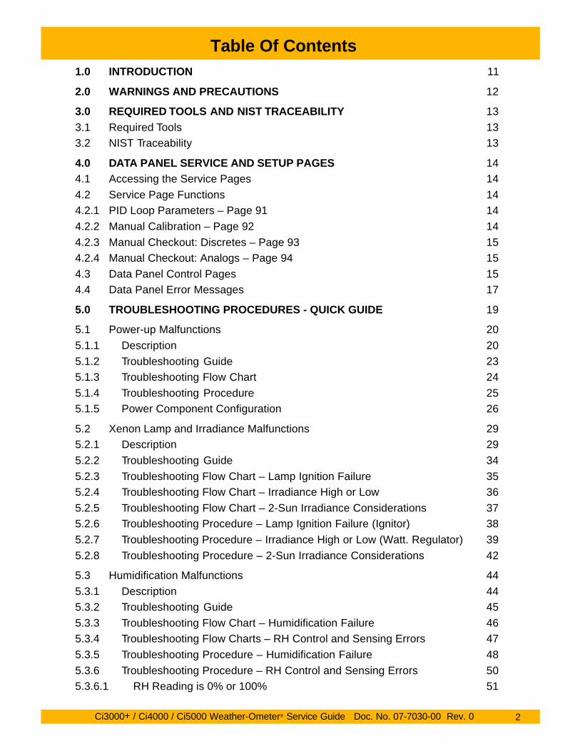
Table Of Contents1.0 INTRODUCTION 11
2.0 WARNINGS AND PRECAUTIONS 12
3.0 REQUIRED TOOLS AND NIST TRACEABILITY 13
3.1 Required Tools 133.2 NIST Traceability 13
4.0 DATA PANEL SERVICE AND SETUP PAGES 144.1 Accessing the Service Pages 14
4.2 Service Page Functions 144.2.1 PID Loop Parameters – Page 91 14
4.2.2 Manual Calibration – Page 92 14
4.2.3 Manual Checkout: Discretes – Page 93 154.2.4 Manual Checkout: Analogs – Page 94 15
4.3 Data Panel Control Pages 154.4 Data Panel Error Messages 17
5.0 TROUBLESHOOTING PROCEDURES - QUICK GUIDE 19
5.1 Power-up Malfunctions 20
5.1.1 Description 20
5.1.2 Troubleshooting Guide 235.1.3 Troubleshooting Flow Chart 24
5.1.4 Troubleshooting Procedure 255.1.5 Power Component Configuration 26
5.2 Xenon Lamp and Irradiance Malfunctions 295.2.1 Description 29
5.2.2 Troubleshooting Guide 34
5.2.3 Troubleshooting Flow Chart – Lamp Ignition Failure 355.2.4 Troubleshooting Flow Chart – Irradiance High or Low 36
5.2.5 Troubleshooting Flow Chart – 2-Sun Irradiance Considerations 375.2.6 Troubleshooting Procedure – Lamp Ignition Failure (Ignitor) 38
5.2.7 Troubleshooting Procedure – Irradiance High or Low (Watt. Regulator) 39
5.2.8 Troubleshooting Procedure – 2-Sun Irradiance Considerations 42
5.3 Humidification Malfunctions 44
5.3.1 Description 445.3.2 Troubleshooting Guide 45
5.3.3 Troubleshooting Flow Chart – Humidification Failure 465.3.4 Troubleshooting Flow Charts – RH Control and Sensing Errors 47
5.3.5 Troubleshooting Procedure – Humidification Failure 48
5.3.6 Troubleshooting Procedure – RH Control and Sensing Errors 505.3.6.1 RH Reading is 0% or 100% 51

Ci3000+ / Ci4000 / Ci5000 Weather-Ometer® Service Guide Doc. No. 07-7030-00 Rev. 0 7
Table Of Contents
List of Figures
Figure 5.1–1 Booster Transformer T1 21Figure 5.1–2 Main Reactor L1 21Figure 5.1–3 Auxiliary Reactor L2 21Figure 5.1–4 Isolation Transformer T2 22Figure 5.1–5 Chamber Safety Thermostat S4 25Figure 5.1–6 Ci3000+ Power Component Configuration Guide 26Figure 5.1–7 Ci4000 Power Component Configuration Guide 27Figure 5.1–8 Ci5000 Power Component Configuration Guide 28Figure 5.2–1 Ci3000+ Xenon Lamp Circuit 30Figure 5.2–2 Ci4000 Xenon Lamp Circuit 31Figure 5.2–3 Ci5000 Xenon Lamp Circuit 32Figure 5.2–4 Xenon Lamp Assembly Guide 33Figure 5.2–5 Ci3000+ Xenon Lamp Ignitor 38Figure 5.2–6 Ci4000 Xenon Lamp Ignitor 38Figure 5.2–7 Ci5000 Xenon Lamp Ignitor 38Figure 5.2–8 Chamber Overtemperature Thermostat 38Figure 5.2–9 Xenon Lamp Wattage Regulator 40Figure 5.2–10 Wattage Regulator Power LED 40Figure 5.2–11 Wattage Regulator Output LED 41Figure 5.2–12 One and Two Sun Circuit Block Diagram 42Figure 5.3–1 Humidification System Plumbing Diagram 44Figure 5.3–2 Air Pressure Regulator Bowl Drain Valve 48Figure 5.3–3 Humidification Nozzle (rear panel) 48Figure 5.3–4 Humidification Nozzle Detail 48Figure 5.3–5 Humidifier Water Line Filter 48Figure 5.3–6 Humidification Block Diagram 49Figure 5.3–7 Humidification Solenoid Valve Locations 49Figure 5.3–8 Humidification Water Control Relay Q1 50Figure 5.3–9 Humidity PC Board Jumpers 50Figure 5.3–10 APC1 Filter PC Board 51Figure 5.4–1 Chamber Safety Thermostat S4 52Figure 5.4–2 Chamber Overtemperature Alarm 52Figure 5.4–3 Chamber Temperature Transmitter 55Figure 5.4–4 Air Heater Control Relay Q2 56Figure 5.5–1 Xenon Lamp Cooling System Electrical Block Diagram 59Figure 5.5–2 CS-6 Lamp Cooling System Plumbing Diagram (Ci3000+) 60Figure 5.5–3 CS-6 Lamp Cooling System Plumbing Diagram (Ci4000/Ci5000) 61Figure 5.5–4 CS-6 Lamp Cooling System 62Figure 5.5–5 Testing the Flow Switch 67Figure 5.5–6 CS-6 Pump Shaft Coupling 67Figure 5.6–1 Lenze 8200 Blower Controller 69Figure 5.6–2 Blower System Electrical Block Diagram 69Figure 5.6–3 Blower Wheel Mounting 73Figure 5.6–4 Lenze Display and Input Select Jumper 75Figure 5.7–1 Black Sensor Transmitter & Collector Ring (Ci4000/Ci5000) 78Figure 5.7–2 Black Sensor Transmitter & Collector Ring (Ci3000+) 78Figure 5.7–3 Temperature Control Systems Electrical Block Diagrams 79Figure 5.7–4 Blower Controller and Chamber Temp. Transmitter (Ci4/Ci5) 80

Ci3000+ / Ci4000 / Ci5000 Weather-Ometer® Service Guide Doc. No. 07-7030-00 Rev. 0 10
Table Of Contents
List of Figures (cont.)
Figure 8.3–6 CS-6 Circulator Pump and Motor 184Figure 8.3–7 Circulator Pump/Motor Coupling 184Figure 8.3–8 CS-6 Pump/Motor Details 184Figure 8.3–9 Ci3000+ and Ci4000 Rack Motors 185Figure 8.3–10 Ci5000 Rack Motor & Controller 185Figure 8.3–11 Rack Drive Gear Alignment 185Figure 8.3–12 Ci4000 Rack Motor Wiring Diagram 186Figure 8.4–1 Rack & Specimen Spray Solenoid Valves 186
Figure 8.4–2 CS-6 and Humidification Solenoid Valves 186
Figure 8.5–1 Rack Speed Controller (Ci5000) 187Figure 8.5–2 Water Resistivity Monitor 187Figure 8.5–3 Transmitter Locations 187Figure 8.5–4 Chamber Overtemperature Alarm 188Figure 8.5–5 Lamp Water Temperature Controller 189Figure 8.5–6 Blower Motor Controller 190Figure 8.5–7 Lenze Display and Input Select Jumper 190Figure 8.5–8 AFE Data Panel Mark I (early Ci4000) 193Figure 8.5–9 AFE Data Panel Mark II 193Figure 8.5–10 Typical PLC Module (side view) 194Figure 8.5–11 PLC0 Fuse 195Figure 8.6–1 Ci4000 Xenon Lamp Ignitor 196Figure 8.6–2 Ci5000 Xenon Lamp Ignitor 196Figure 8.6–3 Ci4000 Ignitor Terminal 196Figure 8.6–4 Ci4000 Ignitor Sealing Washers 196Figure 8.7–1 Xenon Lamp Wattage Regulator 197Figure 8.7–2 Wattage Regulator Trimpots 197Figure 8.8–1 CS-6 Reservoir Tank 198Figure 8.8–2 Level Switch Float Orientation (Dry) 198Figure 8.9–1 Ci4000 Air Heater 198Figure 8.9–2 Ci4000 Rack Hub 198Figure 8.9–3 Ci5000 Rack Hub 198Figure 8.9–4 Air Heater Terminals 200Figure 8.10–1 Collector Ring 200Figure 8.11–1 Rack Bearings 201Figure 8.11–2 Rack Driveshaft Components 201Figure 8.11–3 Ci5000 Rack Hub 201Figure 8.12–1 Chart Recorder Terminals 202Figure 8.12–1 Chart Recorder Electrical Diagram 202
List of Tables
Table 5.6 – 1 Lenze 8200 Blower Motor Controller Setup Codes 77Table 5.13–1 PLC6 Indicator Light Legend 124
Table 8.5–1 Lenze 8200 Blower Motor Controller Setup Codes 192

Ci3000+ / Ci4000 / Ci5000 Weather-Ometer® Service Guide Doc. No. 07-7030-00 Rev. 0 11
1.0 INTRODUCTION
This manual provides instructions for the trouble-shooting, calibration, maintenance and repair orreplacement of all applicable systems and com-ponents of the Ci3000+, Ci4000 and Ci5000Weather-Ometers. These procedures should beperformed only by a qualified service technician.Specifications may be subject to change withoutnotification.
Observe Precautions
Before conducting any procedures, read the warn-ings and precautions in Section 2.0. Doing so willhelp ensure your safety and minimize the poten-tial for damage to the instrument. Beforehand,always read the procedure that you will be con-ducting to become familiar with the steps involved,tools required and safety precautions.
Topics Covered
This manual covers the following topics:
n TroubleshootingPower-up MalfunctionsXenon Lamp & Power Circuit MalfunctionsHumidification MalfunctionsChamber Overtemperature MalfunctionsCS-6 Lamp Cooling System MalfunctionsBlower System MalfunctionsTemperature Control MalfunctionsSpecimen Rack Drive MalfunctionsWater Spray MalfunctionsWater Resistivity Monitor MalfunctionsOptional Chart Recorder MalfunctionsData Panel MalfunctionsPLC (Programmable Logic Controller) MalfunctionsOptional Data Acquisition System MalfunctionsReference Material Test Malfunctions (SRM)
nCalibrationBlack Sensor (BPT and BST)Chamber (dry bulb) SensorRelative HumidityLamp WattageLamp IrradianceAir valve (Damper)Rack Speed ControlResistivity MonitorLamp & Rack Alignment
nMaintenanceLamp Water Fitting GasketLamp Outer Filter CleaningLight Rod End CleaningLamp Burner Socket InspectionTest Chamber CleaningDemineralizer Cartridge ReplacementFlow Switch Filter Screen CleaningLamp Water Reservoir CleaningLight Monitor Filter ReplacementInlet Air Filter CleaningHumidifier Water Filter CleaningHumidifier - Inspection, Cleaning & AdjustmentAir Regulator Oil Trap CleaningLamp, Rack & Light Rod Alignment
nComponent ReplacementRelay ReplacementSensor ReplacementElectric Motor ReplacementSolenoid Valve ReplacementController and Transmitter ReplacementIgnitor ReplacementWattage Regulator ReplacementCS-6 Cooling Coil & Level SwitchesAir Heater ReplacementCollector Ring ReplacementRack Bearing ReplacementChart Recorder ReplacementData Panel and Software Downloading
nAppendixA – PLC and Data Panel Software ConfigurationB – Optional Yokogawa Chart Recorder ManualC – Component Parts Lists
The Troubleshooting section is designed not onlyto help you pinpoint and verify malfunctions, butto provide a basic explanation of operatingprinciples of the various instrument subsystems.Electrical block diagrams, while simplified, includeaccurate component wiring designations.
Additional Questions
If you have questions or encounter problems thatare not addressed in this manual, please contactAtlas Service at (773) 327-4520, or send a fax to(773) 327-5787, Chicago, Illinois U.S.A.

Ci3000+ / Ci4000 / Ci5000 Weather-Ometer® Service Guide Doc. No. 07-7030-00 Rev. 0 29
5.0 TROUBLESHOOTING PROCEDURES
5.2 Xenon Lamp and IrradianceControl Malfunctions
5.2.1 Description
Irradiance is provided by the xenon lamp systemwhich is comprised of the xenon lamp and powersupply components that include the boostertransformer T1, igniter L3, main reactor L1,auxiliary reactor L2 and wattage regulator AR1.
The Ci3000+ has a 4500 watt xenon lamp capableof operating from 1700 to 4500 watts. The 6500watt xenon lamp in the Ci4000 is capable ofoperating within the range of 2500 to 7400 watts.The 12,000 watt lamp in the Ci5000 operates withinthe range of 4000 to 14000 watts.
The xenon lamp receives its high-voltage ignitionpulse from the igniter, which drops out of the circuitafter the lamp is operating steadily. The instrumentis designed to provide three ignition attemptsbefore an ignition failure message is displayed onData Panel MAIN page 1.
At minimum wattage, the lamp receives its powerfrom the main reactor only. At higher wattage levels,the auxiliary reactor and wattage regulator (inseries with the main reactor) contribute additionalpower and provide precision wattage control.
Irradiance control is provided by the light monitorwhich continuously monitors lamp output andprovides a voltage signal to the PLC. The PLC thenincreases or decreases lamp wattage to maintaina stable irradiance level. Lamp wattage iscontinuously monitored by the wattage transducerA1 which provides a voltage signal to the PLC.
Lamp cooling is provided by the CS-6 lamp coolingsystem which pumps filtered D.I. water through thexenon lamp. Heat is extracted from the coolingwater by a tap water coil in the CS-6 reservoir tank.In locations where tap water is expensive or itstemperature is too high, an optional LiquiAir unitor a refrigeration unit may be present to providecooling of the lamp water.
Lamp malfunctions can result from numerouscauses. Ignition of the lamp can be prevented bya damaged or disconnected lamp, a CS-6malfunction, such as low or lost water flow, or bythe malfunction of a lamp circuit component. Lowlamp irradiance output is often the result of burneror lamp filter aging, or expired interference filtersin the light monitor. This section focuses ontroubleshooting of the lamp assembly, lamp circuitcomponents and the light monitor. For CS-6troubleshooting, refer to Section 5.5.
65000W Xenon Lamp

Ci3000 +
/ Ci4000 / C
i5000 Weather-O
meter
® Service G
uide Doc. N
o. 07-7030-00 Rev. 0
30
5.0 TR
OU
BL
ES
HO
OT
ING
PR
OC
ED
UR
ES
5.2X
eno
n L
amp
and
Irradian
ce Co
ntro
l Malfu
nctio
ns
5.2.1 Descrip
tion
(con
t.)
3 4
MAINREACTOR
L1
L1-2
XENONLAMP
XE
5
4
21
1
2
1
53
BOOSTERTRANSFORMER
T1
X3 (15V) X2 (30V)
3 4
X1
L1-1
5 6
K1-4
L1-1
IGNITORL3a
3
2
L1-2
1 2
WA
TTA
GE
TRA
NS
DU
CE
RA
1a (
CO
IL)
L1-2
AUX.REACTOR
L2
12
1 2C1-2 CB2-1
6 7L1-2
WATTAGEREGULATOR
AR132
RE
AR
PC
BFR
ON
T P
CB
2
PLC6-7
PLC6-19
1 (+)
IGNITIONPULSERELAY
K3
6
1
3 4
5
2
IGNITORL3b
PLC6ANALOG OUTPUT
MODULE
WATTAGETRANS-DUCERRELAY
K9
4
3
F1FUSE
INTERNAL.062A250V
TP1
TP2
A1-2
A1-1A1-5
APC1
32 31
APC1
34 33PLC5-8
A1-4(+)
PLC5-10
A1bWATTAGE
TRANSDUCER
1
9
10WATTAGETRANS-DUCERRELAY
K9
RE
SIS
TO
R
500
OH
M PLC5ANALOG INPUT
MODULE
CB2-2
AMPLIFIERRELAY
K5
3 4
XENONLAMP
RELAYK1
IGNITIONCIRCUIT
BREAKERCB2
WATTAGETRANSDUCER
RELAYK9
XENONCIRCUIT
BREAKERCB1
XENONCIRCUIT
BREAKERCB1
XENONLAMP
RELAYK1
IGNITIONCIRCUIT
BREAKERCB2
2
1
4
3
IGNITIONPULSERELAY
K3
C1-2
C1-1
BLEEDERRESISTOR20K OHM
20W
IGNITIONCAPACITOR
C140 mfd
RELAY PLC TERMINAL LED#K1 PLC3-2 A1K3 PLC3-3 A2K5 PLC3-7 A5K9 PLC3-17 B5
RELAY COIL SWITCHING SOURCEAND PLC INDICATOR LIGHTS
NOTE: WHEN PLC LED IS ON PLC CONTACTIS CLOSED TO PROVIDE VOLTAGE TO RELAY.
Figure 5.2
–1 C
i3000 + X
enon Lamp C
ircuit
Ci3000+

Ci3000 +
/ Ci4000 / C
i5000 Weather-O
meter
® Service G
uide Doc. N
o. 07-7030-00 Rev. 0
31
5.0 TR
OU
BL
ES
HO
OT
ING
PR
OC
ED
UR
ES
MAINREACTOR
L1
AUX.REACTOR
L2
IGNITIONPULSERELAY
K3 WATTAGETRANSDUCER
RELAYK9
AMPLIFIERRELAY
K5
XENONLAMPRELAY
K1
XENONLAMP
XE
4
5 3
2
1
2
1
6 7
3 4
4
3
12
1
L1-1
2
5 6
F1FUSE
INTERNAL.062A250V
TP1A1-2
A1-5
APC1
32 31
APC1
34 33PLC5-8
A1-4(+)
PLC5-10
A1bWATTAGE
TRANSDUCER
RE
SIS
TO
R
500
OH
M PLC5ANALOG INPUT
MODULE
TP2A1-1
1 2
WATTAGETRANS-DUCERRELAY
K9
4
3C1-2
C1-1
WATTAGEREGULATOR
AR1
RE
AR
PC
BFR
ON
T PC
B
2
PLC6-7
PLC6-19
1 (+)
PLC6ANALOG OUTPUT
MODULE
7
32
10
9
CB2-2
IGNITIONCIRCUIT
BREAKERCB2
3 4
IGNITIONPULSERELAY
K3
6
5
2
1
BLEEDERRESISTOR56K OHM
3 4
3
4
C2 C3
BOOSTCAP. RELAY
K4
56Κ
Ω
56Κ
Ω
XENONCIRCUIT
BREAKERCB1
1 2
3 4
BOOSTERTRANSFORMER
T1
2 3
1
XENONCIRCUIT
BREAKERCB1
XENONLAMP
RELAYK1
C2-1VOLTAGE
BOOSTCAPACITORS
(40 MFD)
C3-1
C3-2C2-2
TB2-2
L1-2L1-2
IGNITORL3a
IGNITORL3b
WATTAGETRANSDUCER
A1a (COIL)
IGNITIONCIRCUIT
BREAKERCB2
WATTAGETRANS-DUCERRELAY
K9
RESISTORR4
1.8K OHM2W
TB2-2TB2-2
IGNITIONCAPACITOR
C1
L1-1
RELAY PLC TERMINAL LED#K1 PLC3-2 A1K3 PLC3-3 A2K5 PLC3-7 A5K9 PLC3-17 B5
RELAY COIL SWITCHING SOURCEAND PLC INDICATOR LIGHTS
NOTE: WHEN PLC LED IS ON PLC CONTACTIS CLOSED TO PROVIDE VOLTAGE TO RELAY.
Figure 5.2
–2 C
i4000 Xenon Lam
p Circuit
5.2X
eno
n L
amp
and
Irradian
ce Co
ntro
l Malfu
nctio
ns
5.2.1 Descrip
tion
(con
t.)
Ci4000

Ci3000 +
/ Ci4000 / C
i5000 Weather-O
meter
® Service G
uide Doc. N
o. 07-7030-00 Rev. 0
32
5.0 TR
OU
BL
ES
HO
OT
ING
PR
OC
ED
UR
ES
AUX.REACTOR
L2
IGNITORL3
XENONLAMP
XE
HIG
H V
OLT
AG
E
TRA
NS
FOR
ME
R T
4
STEP DOWNTRANSFORMER
T3
IGNITIONCAP. RELAY
K3
WATTAGETRANS-DUCERRELAY
K9
3 4
3
4
2
1
4
3
11
52
1
10
7
8
3 4 6 71 2
L1-1
4
3 41
MAINREACTOR
L1
7 6TB6-1
12
LOW
HI
LOW COM
4 33
4
K151-SUN
K42-SUN
60Hz
TB6-1
W
R
2
WATTAGEREGULATOR
AR1
RE
AR
PC
BFR
ON
T PC
B
2
PLC6-7
PLC6-19
1 (+)
PLC6ANALOG OUTPUT
MODULE
2
13
460V
230V
TP 2
TP 1
1
2
FUSE63 mA
SLO-BLO
RE
SIS
TO
R
500
OH
M
A1-5
APC1
34 33PLC5-8
APC1
32 31A1-4(+)
PLC5-10
PLC5ANALOG INPUT
MODULE
1 2
IGNITIONCIRCUIT
BREAKERCB2
IGNITIONPULSERELAY
K3
IGNITORL3
HIG
H V
OLT
AG
E
TRA
NS
FOR
ME
R T
4
6
7
5
3
4
2
1
6
w/b
brn
w/b
blk
3 4
9
10
32
7
BLEEDERRESISTOR56K OHM
IGNITIONCAPACITOR
C1(80 MFD)
WATTAGETRANSDUCER
A1a (COIL)
WATTAGETRANS-DUCER
A1b
K1-4 CB2-1 CB2-2
BOOSTERTRANSFORMER
T1
1 2
2 3
1
T1-1
WATTAGETRANSDUCER
RELAYK9
AMPLIFIERRELAY
K5
XENONLAMPRELAY
K1
IGNITIONCIRCUIT
BREAKERCB2
XENONCIRCUIT
BREAKERCB1
WATTAGETRANS-DUCERRELAY
K9
XENONCIRCUIT
BREAKERCB1
XENONLAMPRELAY
K1
RELAY PLC TERMINAL LED#K1 PLC3-2 A1K3 PLC3-3 A2K5 PLC3-7 A5K9 PLC3-17 B5
RELAY COIL SWITCHING SOURCEAND PLC INDICATOR LIGHTS
NOTE: WHEN PLC LED IS ON PLC CONTACTIS CLOSED TO PROVIDE VOLTAGE TO RELAY.
Figure 5.2
–3 C
i5000 Xenon Lam
p Circuit
5.2X
eno
n L
amp
and
Irradian
ce Co
ntro
l Malfu
nctio
ns
5.2.1 Descrip
tion
(con
t.)
Ci5000

Ci3000 +
/ Ci4000 / C
i5000 Weather-O
meter
® Service G
uide Doc. N
o. 07-7030-00 Rev. 0
33
5.0 TR
OU
BL
ES
HO
OT
ING
PR
OC
ED
UR
ES
Figure 5.2–4 Xenon Lamp Assembly Guide
Burner Tip Must Not BeVisible Beside Socket
End View of LampIncorrectCorrect
Union Ring
Union Ring
Union Ring
Union Ring
Mounting Ring
LampWaterFitting
Union Ring
Union Ring
OuterFilter
Union Ring Union Ring Union Ring
InnerFilter
LowerFilterHousing
Union Ring
Spring
BurnerSocket
BurnerSocket
UpperFilter
Housing
SealingWasher
Union Ring
XenonBurner
BurnerBase
Union Ring
AlignmentPin
AlignmentPin
Washer
Washer
Pin
Install the twosealing washersonto the outerfilter ends if noneare in place.
Check that the burner tipis inside the socket asshown. Gently handtighten the union ring.
Clean the outer filter withan optical cleaner or a 1:1mixture of alcohol andacetone. Hold the lamp bythe upper or lower filterhousing only.
Check that there is asealing washer inside thelamp water fitting.Connect the lamp androtate it until thealignment pin falls intoplace. Gently handtighten the mounting ring.
Connect the upperfilter housing to theouter filter. Be sureto match thealignment pin andhole. Gently handtighten.
Hold the lampsideways, andslowly slide theinner filter into theouter filter. Do NOTdrop the inner filterin place or damagemay occur.
Check that the springinside the lower filterhousing tube is in place.Connect the lower filterhousing to the outer filter.Gently hand tighten theunion ring.
Turn the lamp upsidedown. Check that thesealing washer is inplace on the burnerbase. Slide theburner up into theburner socket. Lookdown through thelower filter housing toensure that theburner tip is insidethe burner socket.
Lamp Electrode
OuterFilter
5.2X
eno
n L
amp
and
Irradian
ce Co
ntro
l Malfu
nctio
ns (co
nt.)

Ci3000+ / Ci4000 / Ci5000 Weather-Ometer® Service Guide Doc. No. 07-7030-00 Rev. 0 34
5.0 TROUBLESHOOTING PROCEDURES
5.2 Xenon Lamp and Irradiance Control Malfunctions (cont.)
5.2.2 Troubleshooting Guide
MALFUNCTION PROBABLE CAUSE CORRECTIVE ACTION
Lamp fails to ignite Chamber door open or switch failure Close door or check switch.
Xenon lamp/ignition breakers off Turn on circuit-breakers.
Lamp assembled/installed incorrectly Check lamp.
Lamp ignitor lead off or loose Check lead connections.
Light rod dirty or damaged Inspect/clean light rod.
Light monitor malfunction Check filters & photodiodes.
Lamp burner socket damaged Inspect/replace (Sec. 7.2.4).
Low lamp starting voltage Check/adjust taps on T1 and L1.
CS-6 cooling water flow low Check CS-6 (see Section 5.5)
Ignitor malfunction Conduct procedure in 5.2.6.
Relay failure in lamp circuit Conduct procedure in 5.2.6.
PLC malfunction Conduct procedure in 5.2.6.
Lamp output is high/low Burner is near end of life Replace xenon burner.
Lamp filters expired Replace lamp filters.
Burner tip/socket damaged Inspect/replace socket or burner.
Incorrect irradiance calibration Recalibrate (Section 6.9).
Interference filters expired Check/replace filters (Sec. 7.2.9).
Light rod is misaligned Align light rod (Secs. 7.2.14 & .15)
Wattage regulator malfunction Conduct procedure in 5.2.7.
Lamp will not operate 1-Sun or 2-Sun relay failure Perform procedure 5.2.8.above 1-Sun level(Ci5000 only)
Lamp operating at Burner is near end of life Replace xenon burner.
excessive wattage Lamp filters expired Replace lamp filters.
Burner tip/socket damaged Inspect/replace socket or burner.
Incorrect irradiance calibration Recalibrate (Section 6.9).
Interference filters expired Check/replace filters (Sec. 7.2.9).
Light rod is misaligned Align per Section 7.2.14 or 7.2.15.
Wattage regulator malfunction Conduct procedure in 5.2.7.
No wattage display Blown fuse F1 on A1 transducer Check fuse.
A1 wattage transducer board failure Check board output w/ lamp on.

Ci3000+ / Ci4000 / Ci5000 Weather-Ometer® Service Guide Doc. No. 07-7030-00 Rev. 0 35
5.0 TROUBLESHOOTING PROCEDURES
5.2 Xenon Lamp and Irradiance Control Malfunctions (cont.)
5.2.3 Troubleshooting Flow Chart - Lamp Ignition Failure
3) Check for messageson Data Panel MAINpage 1.
2) Check lamp for age,damage, proper installa-tion and ignitor lead con-nections.
5) Check for line voltageto ignitor during pulse.
1) Confirm Xenon andIgnition circuit-breakersare on.
6) Check for continuitybetween relay terminalsK3-5 & K3-6 (Ci3 & Ci4)or K3-6 & K3-7 (Ci5)*.
4) Initiate standard testno. 1.
7) Check for 24Vac atrelay K3 coil during pulse.
8) Check for continuity atterminals PLC3-1 andPLC3-3 during pulse.
Messagesdisplayed
“Lamp Water Temperature High”“Lamp Water Flow is Low”
Check CS-6 cooling system(Section 5.5).
“Chamber Temperature is High”Reset chamber safety thermo-stat S4 in electronics drawer.
Ignition pulseis audible
Install calibrated lampand attempt ignition.
Lampignites
Lamp doesnot ignite
Previous lamp is malfunc-tioning. Inspect for dam-age. Check burner socket.
Measure line voltage andcheck transformer taps.Set T1 lamp voltage boostto next higher selection(see Section 5.1.5).
Also check light rod clean-liness/integrity and lightmonitor filters and photo-diodes (Sec. 7.2.9).
Ignition pulseis not audible
Voltage ispresent
On Ci3000+ and Ci4000,replace ignitor. OnCi5000 check 1&2-Sunrelays K15 and K4.No voltage
present
Continuity
NoContinuity
Check voltage at breakerCB2. If no voltage, replacebreaker.
Voltage ispresent
No voltagepresent
Coil has failed. Replacerelay K3.
Nocontinuity
Continuity
If LED A2 on PLC3 moduleis on during pulse, replacePLC3 module. If the LEDis off, download softwareprogram to PLC (seeAppendix A & Sec. 5.13.5).
9) Check for 24Vac atTB3-7 & TB3-9 (Ci4) orTB3-5 & TB3-8 (Ci5).
No voltage Check breaker CB5 and T2output at T2-X3 & T2-X4.
Replace failed breaker ortransformer T2.
*Ci3 denote Ci3000+Ci4 denotes Ci4000Ci5 denotes Ci5000

Ci3000+ / Ci4000 / Ci5000 Weather-Ometer® Service Guide Doc. No. 07-7030-00 Rev. 0 36
5.0 TROUBLESHOOTING PROCEDURES
5.2 Xenon Lamp and Irradiance Control Malfunctions (cont.)
5.2.4 Troubleshooting Flow Chart - Irradiance High or Low
3) Confirm light monitoroutput at PLC5-11 & -13(or at PLC5-12 & -14 for2nd light sensor).
2) Initiate standard testno. 1.
5) Observe upper greenPower LED on wattageregulator.
1) Perform Wattage Cali-bration and IrradianceCalibration procedures.
6) Check drive currentsignal to wattage regu-lator terminal AR1-1.Should be approx. 4mA.
4) Initiate custom watt-age-controlled test atminimum lamp wattage.
No output
Current iszero or wellabove 4mA
Potential PLC6 modulefailure. Confirm below.
Check light monitor filters& photocells (Sec. 7.2.9).
LED is offCheck for continuity atrelay K9 (K9-9 & K9-10).
ContinuityR4 is open-circuited orwattage regulator failed.
Nocontinuity
Check for 24Vac acrossrelay K9 coil terminals.
Voltagepresent
No voltagepresent
Replacerelay K9.
If B5 LED on PLC3 ison, replace PLC3. IfLED is off, downloadsoftware to PLC. Ifoperation not restored,replace PLC3. SeeSection 5.13.5.
7) Initiate custom mid-range wattage test at:Ci3-3000W, Ci4 – 5000WCi5 – 8000W
8) Observe lower greenOutput LED on wattageregulator.
LED dim oroff & drive
current wellabove 4mA
Replace the wattageregulator.
Drivecurrent isstill 4mA,zero or
unstable
Replace PLC6 AnalogOutput module (seeSection 5.13.8 first).
Run mid-range wattagetest again. Drive signalshould be approximately9 to 11mA.
Drivecurrent in
range
Drive currentstill zero or
out of range.
Replace the CPUmodule of the PLC (seeSec. 5.13.3). Run mid-range wattage testagain and check drivesignal current.
Run standard test no.1 and confirm stableirradiance within testtolerance.
Drivecurrent in
range
Reinstall old PLC6module & confirmoperation by runningstandard test no. 1.

Ci3000+ / Ci4000 / Ci5000 Weather-Ometer® Service Guide Doc. No. 07-7030-00 Rev. 0 37
5.0 TROUBLESHOOTING PROCEDURES
5.2 Xenon Lamp and Irradiance Control Malfunctions (cont.)
5.2.5 Troubleshooting Flow Chart - 2-Sun Irradiance Considerations (Ci5000 only)
2) Check for rack speedof 10 RPM.
Rack at1 RPM
Nocontinuity
Relay K14 or A14 rackspeed controller ismalfunctioning.
3) Check for continuitybetween K14 relay termi-nals K14-3 and K14-4.
Continuity Check for 0 volts betweenground and relay K15terminal K15-3. If voltagepresent, K15 or K14 isstuck closed. Replace badrelay.
4) Check for 24Vac atK14 coil terminals K14-1and K14-2. Voltage
present
No voltage
Replace relay K14.
5) With K14 operatingproperly, check for volt-age between ground andK4 relay terminal K4-3. No voltage
present
Voltagepresent
Relay K4 is o.k.
Check for 24Vac at K4coil terminals K4-1 andK4-2. If no voltage ispresent, replace K4. Ifvoltage is present, re-place PLC3 Logic Outputmodule (see Sec. 5.13.5first).
1) Create and initiate acustom 2-Sun test.
If A8 LED on PLC3 ison, replace PLC3. IfLED is off, downloadsoftware to PLC. Ifoperation not restored,replace PLC3. SeeSection 5.13.5.

Ci3000+ / Ci4000 / Ci5000 Weather-Ometer® Service Guide Doc. No. 07-7030-00 Rev. 0 38
5.0 TROUBLESHOOTING PROCEDURES
5.2 Xenon Lamp and IrradianceControl Malfunctions (cont.)
5.2.6 Troubleshooting Procedure –Lamp Ignition Failure (Ignitor)
1) Ensure that the xenon lamp is properly installedand that the ignitor lead is firmly secured to thelamp electrode. Also ensure that the lamp leadconnection to the ignitor terminal is secure andfree of corrosion.
2) Confirm that the Xenon Lamp and Ignitioncircuit-breakers are turned on.
3) Check for messages on the Data Panel MAINpage 1 Messages display.
A) Check the CS-6 lamp cooling system(Sec. 5.5) if one of these messages appears:
Lamp Water Temperature HighLamp Water Flow is Low
B) If the message “Chamber Temperature isHigh” is displayed, reset the chamber safetythermostat (S4) inside the electronics drawer.Press the red reset button on the thermostat.
4) Initiate standard test no. 1 to attempt lampignition.
5) If the ignition start pulse is audible (up to 4attempts), but the lamp will not ignite, the problemis either the lamp itself or low lamp-circuit voltage.
A) Install the calibrated reference lamp andinitiate the test. If the lamp lights, then thepreviously installed xenon lamp ismalfunctioning. Examine it for damage,burner tip and socket damage or corrosion.Check the burner age as recorded on theXenon Burner Warranty Log card. The lampmay be at the end of its life (1200 hours ormore).
B) If the calibration lamp will not ignite,measure line voltage to the instrument and
Figure 5.2 – 8 Chamber Overtemperature Thermostat
S4
Figure 5.2 – 6 Ci4000 Xenon Lamp Ignitor
Figure 5.2 – 7 Ci5000 Xenon Lamp Ignitor
Figure 5.2 – 5 Ci3000+ Lamp Ignitor & LS-8
Ignitor LS-8Light
Monitor

Ci3000+ / Ci4000 / Ci5000 Weather-Ometer® Service Guide Doc. No. 07-7030-00 Rev. 0 39
5.0 TROUBLESHOOTING PROCEDURES
check the transformer tap connections asdescribed in Section 5.1.1. Set the T1 boostertransformer lead T1-3 to the next higher lampboost voltage terminal. Re-attempt lampignition. If the lamp still does not ignite,continue below.
Also check the light rod for cleanliness anddamage. Confirm the LS-8 light sensorinterference filters have not expired and thatthe photodiodes are functional (Sec. 7.2.9).
CAUTION: SHOCK HAZARD.Conduct step 6 below withmeter leads clipped onto the
specified terminals. DO NOT hold probesonto the terminals during lamp ignition orelectric shock and injury may result.
Note: In the steps below you must shut theinstrument off with the front panel powerswitch after each attempt at igniting the lamp.This will reset the lamp starting circuit.
6) Check voltage to the ignitor: Connect a voltmeter(with clip leads) to terminals L3-1 and L3-2. Attemptlamp ignition while watching the meter. The metershould indicate line voltage (230V or 480V) duringthe ignition pulse.
A) If line voltage is present during the ignitionpulse, the ignitor has failed. Replace it (seeSection 8.6).
B) If no voltage is present, continue below.
7) Check relay K3 operation: During an ignitionattempt, check for continuity between the terminalsof Ignition Pulse Relay K3. There should becontinuity for 1 second during each ignition pulsebetween terminals:
5.2 Xenon Lamp and IrradianceControl Malfunctions (cont.)
5.2.6 Troubleshooting Procedure –Lamp Ignition Failure (Ignitor) (cont.)
Ci3/4000 - Terminals K3-5 and K3-6Ci5000 - Terminals K3-6 and K3-7
A) If there is continuity across the K3 contactsduring the ignition pulse, then there is aproblem with the line voltage supply to therelay. Check wiring to the relay and voltageat the CB2 Ignition circuit-breaker terminalsCB2-2 and CB3-4. There should be linevoltage between each terminal and ground.If not, replace the circuit-breaker.
B) If the relay does not activate, its coil isbad or the PLC is not sending it an activationsignal or the 24Vac supply to the PLC is bad.
B1) Check for 24Vac on the relay coil duringthe ignition pulse. If 24Vac is present, the coilis bad. Replace the relay (see Section 8.1).
B2) During the ignition pulse, check forcontinuity between terminals PLC3-1 andPLC3-3. If there is no continuity, and the A2LED on PLC3 is on, replace the module (seeSection 5.13.5 first). If A2 is off, downloadthe PLC software program to the PLC.
B3) Check for continuous 24Vac across:
Ci3/4000 – TB3-7 and TB3-9Ci5000 – TB3-5 and TB3-8
This is the 24Vac supply to the 24Vac controlcircuit. If 24Vac is not present, check circuit-breaker CB5 and the 24Vac output of theisolation transformer T2 at terminalsT2-X3 and T2-X4. Replace the failed breakeror transformer.
5.2.7 Troubleshooting Procedure – IrradianceLow or High (Wattage Regulator)
To maintain an accurate and stable irradiance levelduring a test, the PLC receives a signal from thelight monitor (at PLC5-11/-13 or PLC2-12/-14),compares it to the irradiance setpoint reference,and then alters its output (at PLC6-7/-19) toincrease or decrease wattage regulator output.

Ci3000+ / Ci4000 / Ci5000 Weather-Ometer® Service Guide Doc. No. 07-7030-00 Rev. 0 40
5.0 TROUBLESHOOTING PROCEDURES
This drive signal is applied to terminals AR1-1 andAR1-2 of the wattage regulator AR1.
Troubleshooting consists of first confirming lightmonitor operation and its output signal to the PLC.Then the instrument is operated at constantwattage and the PLC output signal to the wattageregulator is checked. If a stable drive signal ispresent, but lamp operation is erratic or out ofwattage tolerance, it is likely that the wattageregulator is malfunctioning.
1) Perform the Wattage Calibration (Sec. 6.8) andthen the Irradiance Calibration (Sec. 6.9) toeliminate calibration as a contributive factor.
2) Initiate standard test no. 1 SAE J-1885. Set itup so the lamp will operate for 30 minutes.
3) With the lamp operating, confirm that the voltagesignal from the light monitor is present at the PLC
5.2 Xenon Lamp and IrradianceControl Malfunctions (cont.)
5.2.7 Troubleshooting Procedure – IrradianceLow or High (Wattage Regulator) (cont.)
terminals PLC5-11 and PLC5-13 (or at terminalsPLC5-12 and PLC5-14 if the optional sensor isinstalled and is controlling irradiance).
A) If no voltage is present, there is a problemwith the light sensor wiring, interference filteror the photocell. Check each of these beforecontinuing (See Section 7.2.9).
B) If the signal is present, the light monitor isfunctioning properly.
4) Shut off all power to the instrument at the wall-mounted disconnect switch.
5) Disconnect the AR1-1 lead from the wattageregulator and connect an ammeter in series with
the lead and terminal AR1-1. This will allowmeasurement of the 4-20mA drive signal from thePLC to the wattage regulator.
6) Apply power to the instrument. Initiate a customtest using wattage control rather than irradiancecontrol. Set the wattage level to minimum for thelamp type in use (1700 watts for Ci3000+, 2500watts for Ci4000, 4000 watts for Ci5000). Set thetest duration to 30 minutes.
7) Observe the LED indicator lights on the wattageregulator. With power on and the xenon lampoperating, the upper green lamp should be onindicating that the regulator is receiving power.
Figure 5.2 – 10 Wattage Regulator Power LED
PowerLED
Figure 5.2 – 9 Xenon Lamp Wattage Regulator

Ci3000+ / Ci4000 / Ci5000 Weather-Ometer® Service Guide Doc. No. 07-7030-00 Rev. 0 41
5.0 TROUBLESHOOTING PROCEDURES
A) If the LED is off, check for continuity acrossterminals K9-9 and K9-10 of relay K9. If thereis continuity, then resistor R4 (Ci4 only) isopen-circuited or the wattage regulator hasfailed. Replace the regulator per Section 8.7.
B) Check for 24Vac volts across the K9 relaycoil terminals K9-1 and K9-2.
B1) If voltage is present, and there is nocontinuity between terminals K9-9 andK9-10, replace relay K9 per Section 8.1.
B2) If voltage is not present, and the B5LED on PLC3 is on, replace the PLC3module (see Section 5.13.5). If B5 is off,download the software program to thePLC. If this fails to restore operation,replace PLC3.
8) Observe the ammeter on the AR1-1 terminal. Itshould display a reading of approximately 4mA.
A) If the ammeter reading is zero, or wellabove 4mA, there is potentially a problem
5.2 Xenon Lamp and IrradianceControl Malfunctions (cont.)
5.2.7 Troubleshooting Procedure – IrradianceLow or High (Wattage Regulator) (cont.)
Figure 5.2 – 11 Wattage Regulator Output LED
SoftStartLED
OutputLED
with the PLC Analog Output PLC6 module.(This will be checked in a later step.)
9) Stop the wattage test and alter it to the mid-range operating wattage level shown below.
Ci3000+ – 3000 wattsCi4000 – 5000 wattsCi5000 – 8000 watts
10) Initiate the new test to ignite the lamp.
11) Observe the green LED indicator light on thelower circuit board of the wattage regulator. Thisis the output indicator and becomes brighter asoutput increases. It should be on brightly.
A) If the LED is very dim or off, and theammeter reading is well above 4mA, thereis a problem with the wattage regulatoroutput. Replace the regulator (Section 8.7).
B) If the ammeter reading is zero, still at 4mAor is unstable, there is a problem with thePLC Analog Output PLC6 module or the PLCCPU (PID settings, corrupt PLC software orCPU failure).
B1) Replace the PLC6 module (see Sec.5.13.8 first). Run the mid-range wattagetest again. Check the level and stabilityof the ammeter reading. It should be verystable and approximately 5 to 10 mA.
B2) If replacement of the PLC6 moduledoes not correct the problem, downloadthe custom programs from the PLC to alaptop computer and replace the CPUmodule of the PLC (see Sections 5.13 andAppendix A). Upload the custom pro-grams and the correct PLC operatingsoftware. Run the mid-range wattage testagain and observe the ammeter readingfor stability. If this corrects the problem,reinstall the old PLC6 module and confirmoperation.

Ci3000+ / Ci4000 / Ci5000 Weather-Ometer® Service Guide Doc. No. 07-7030-00 Rev. 0 42
5.0 TROUBLESHOOTING PROCEDURES
If the xenon lamp in the Ci5000 fails to operate athigher (2-Sun) irradiance levels, there may be amalfunction of the 1-Sun or 2-Sun relays, or thecomponents driving them (Fig. 5.2–9). Additionally,if the error message “Test Irrad. Not Match withFilters” appears on the screen at the start of a test,it indicates that the irradiance level chosen is inthe 2-Sun range and you must recalibrate the lampfor this irradiance level.
2-Sun irradiance levels are defined as follows:
0.70 W/m2 or higher @ 340 nm filter1.40 W/m2 or higher @ 420 nm filter75.0 W/m2 or higher @ 300-400 nm filter
At 1-Sun irradiance levels, the rack rotates at 1RPM. At 2-Sun levels it rotates at 10 RPM. RelayK14 switches the input to the rack speed controller.Conduct the procedure below to determine thecause of 2-Sun operation failure.
5.2 Xenon Lamp and IrradianceControl Malfunctions (cont.)
5.2.8 Troubleshooting Procedure – 2-SunIrradiance Considerations
1) Program a custom, 2-sun irradiance test withthe parameters shown below.
Test List (Data Panel page 6)Select an unused Custom test. Press F6, the testnumber and Enter three times. Press F2.
Test Criteria (Data Panel page 7)Total Segments 1Duration Units TimeBlack Sensor BPTBlack Temp. Active YesRadiation@filter 340 nmChamber Temp. Active No
Segment (Data Panel page 8)Segment Number 1Light or Dark LightTime or Irradiance 30 min.Irradiance 1.50 W/m2
Black Temp. 80 °CChamber (DB) Temp. 60 °CRelative Humidity 0 %
Segment (cont.) (Data Panel page 9)Set sprays to off.
Test List (Data Panel page 6)Press F8. Press F5, the custom test number andEnter three times to load the new custom test.
Run/Stop Segment (Data Panel page 3)Test Duration 0 hours 30 min
2) Press F4 on RUN/STOP page 3 to start the test.
CAUTION: SHOCK HAZARDIn the procedures below, youmust check for voltages at liveelectrical terminals. Avoid
contact with component terminals andwear insulated gloves to prevent electricalshock.
3) When the Ci5000 is running a test at2-Sun irradiance level, the rack should be rotatingat 10 RPM. Check rack speed. If it is rotating at 1RPM, relay K14 or the rack speed control A14 ismalfunctioning (see Section 5.8).
3
4
COIL
K15ONESUN
RELAY
TB3-11
COIL
K14RACK
SPEEDRELAY
A14-S2
A14-S1R210K
A14-S3K14-3K14-4
K14-9
K14-1 K14-2TB3-9
K15-2
K15-1
L1MAIN
REACTORCOIL
K4TWOSUN
RELAY
3
4
K4-1
K4-2
L3IGNITOR
L2-2K3-3
TB6-124VacTB3-5TB3-6TB3-7
PLC3-10
L3-12
TB6-1
K14-11
LOW
HI
PLC3-5
LOW COM
A14RACK
MOTORSPEED
CONTROL
TB3-824Vac
N.C.N.C.
TB2-2
PLC3LOGIC
OUTPUTMODULE
A8
PLC3LOGIC
OUTPUTMODULE
A4
Figure 5.2 – 12 One and Two Sun Circuit Block Diagram
Ci3000+ / Ci4000 / Ci5000 Weather-Ometer® Service Guide Doc. No. 07-7030-00 Rev. 0 43
5.0 TROUBLESHOOTING PROCEDURES
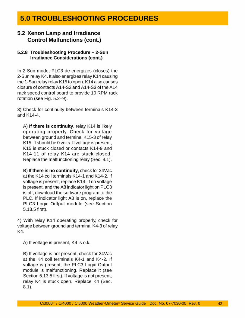
In 2-Sun mode, PLC3 de-energizes (closes) the2-Sun relay K4. It also energizes relay K14 causingthe 1-Sun relay relay K15 to open. K14 also causesclosure of contacts A14-S2 and A14-S3 of the A14rack speed control board to provide 10 RPM rackrotation (see Fig. 5.2–9).
3) Check for continuity between terminals K14-3and K14-4.
A) If there is continuity, relay K14 is likelyoperating properly. Check for voltagebetween ground and terminal K15-3 of relayK15. It should be 0 volts. If voltage is present,K15 is stuck closed or contacts K14-9 andK14-11 of relay K14 are stuck closed.Replace the malfunctioning relay (Sec. 8.1).
B) If there is no continuity, check for 24Vacat the K14 coil terminals K14-1 and K14-2. Ifvoltage is present, replace K14. If no voltageis present, and the A8 indicator light on PLC3is off, download the software program to thePLC. If indicator light A8 is on, replace thePLC3 Logic Output module (see Section5.13.5 first).
4) With relay K14 operating properly, check forvoltage between ground and terminal K4-3 of relayK4.
A) If voltage is present, K4 is o.k.
B) If voltage is not present, check for 24Vacat the K4 coil terminals K4-1 and K4-2. Ifvoltage is present, the PLC3 Logic Outputmodule is malfunctioning. Replace it (seeSection 5.13.5 first). If voltage is not present,relay K4 is stuck open. Replace K4 (Sec.8.1).
5.2 Xenon Lamp and IrradianceControl Malfunctions (cont.)
5.2.8 Troubleshooting Procedure – 2-SunIrradiance Considerations (cont.)

Ci3000+ / Ci4000 / Ci5000 Weather-Ometer® Service Guide Doc. No. 07-7030-00 Rev. 0 180
8.0 REPAIR & REPLACEMENT PROCEDURES
8.2 Sensor Replacement (cont.)
8.2.7 Light Monitor Photodiodes
The LS-8 Light Monitor, used on the Ci5000,Enhanced Ci4000and Ci3000+, includes one ortwo capsules that contain an interference filter anda photodiode. Light from the xenon lamp istransmitted to the photodiode via the quartz lightrod. The photodiode produces a microampere (µA)output proportional to the light intensity it receivespassing through the interference filter.
Older Ci4000 instruments have either a single lightsensor in a sheetmetal enclosure or an optionaldual band sensor in a machined aluminumhousing.
In all three light monitors, the types of photodiodesused are the same, but their mountings differ.
Note: The photodiode used with a 340 or420nm narrow-band interference filter isdifferent than the one used with a 300-400nm wide-band filter. Do not mix them.
Photodiode Part Numbers340nm 420 nm 300-400 nm
OlderCi4000 09-3515-00 09-3515-00 09-3493-00
Ci3+, Ci5& Ci4000 09-3529-00* 09-3530-00* 09-3531-00*Enhanced
*LS-8 capsule assembly including photodiode
Light RodConnector
CapsuleCover
Optional Channel 2Interference Filter
(300-400nm shown)
O-RingChannel 2Capsule &Photodiode
A13
Beam Splitter (not presenton single bandwidth units)
Channel 1Capsule &Photodiode
A10
Channel 1Interference Filter
(340/420nm shown)
Ci3000+, Ci5000 & Enhanced Ci4000 Light Sensor
Photodiode
O-Ring
InterferenceFilter
Leads forcode
jumpering
Figure 8.2 – 7 LS-8 Light Sensor Capsule Assembly Figure 8.2 – 8 Dual Bandwidth Light Sensors
Older Ci4000 Dual Bandwidth Light Sensor
O-ring
FilterHousing
Interference Filter(Note orientation
of arrow)
Filter Housing andBeam Splitter
A10 PhotodiodeSensor Cell #1
A13 PhotodiodeSensor Cell #2
Light Path
Interference Filter(Note orientation
of arrow)
HousingCover
Ci3000+ / Ci4000 / Ci5000 Weather-Ometer® Service Guide Doc. No. 07-7030-00 Rev. 0 181
8.0 REPAIR & REPLACEMENT PROCEDURES
SensorHousing
InterferenceFilter (Note
orientation ofarrow)
DO NOT removescrews in this location
A10 PhotodiodeSensor Cell
Filter HousingCap
SensorHousing Cover
8.2 Sensor Replacement (cont.)
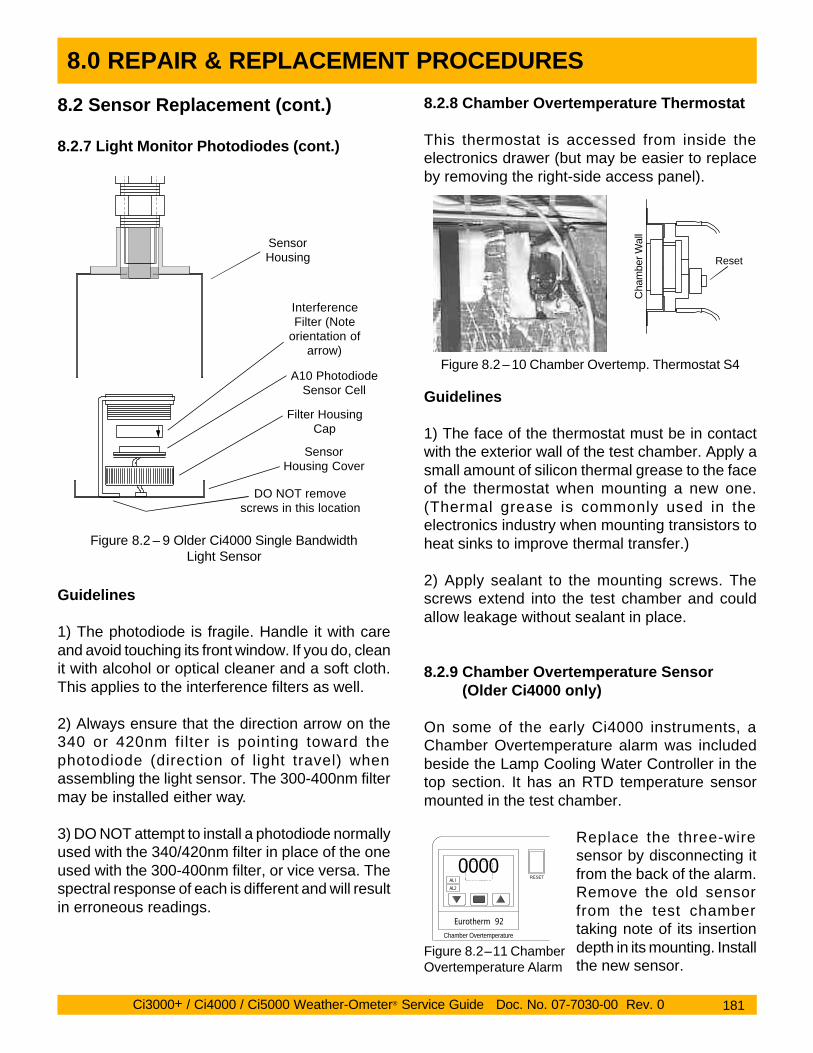
8.2.7 Light Monitor Photodiodes (cont.)
Figure 8.2 – 9 Older Ci4000 Single BandwidthLight Sensor
Guidelines
1) The photodiode is fragile. Handle it with careand avoid touching its front window. If you do, cleanit with alcohol or optical cleaner and a soft cloth.This applies to the interference filters as well.
2) Always ensure that the direction arrow on the340 or 420nm filter is pointing toward thephotodiode (direction of light travel) whenassembling the light sensor. The 300-400nm filtermay be installed either way.
3) DO NOT attempt to install a photodiode normallyused with the 340/420nm filter in place of the oneused with the 300-400nm filter, or vice versa. Thespectral response of each is different and will resultin erroneous readings.
8.2.8 Chamber Overtemperature Thermostat
This thermostat is accessed from inside theelectronics drawer (but may be easier to replaceby removing the right-side access panel).
Guidelines
1) The face of the thermostat must be in contactwith the exterior wall of the test chamber. Apply asmall amount of silicon thermal grease to the faceof the thermostat when mounting a new one.(Thermal grease is commonly used in theelectronics industry when mounting transistors toheat sinks to improve thermal transfer.)
2) Apply sealant to the mounting screws. Thescrews extend into the test chamber and couldallow leakage without sealant in place.
8.2.9 Chamber Overtemperature Sensor(Older Ci4000 only)
On some of the early Ci4000 instruments, aChamber Overtemperature alarm was includedbeside the Lamp Cooling Water Controller in thetop section. It has an RTD temperature sensormounted in the test chamber.
Replace the three-wiresensor by disconnecting itfrom the back of the alarm.Remove the old sensorfrom the test chambertaking note of its insertiondepth in its mounting. Installthe new sensor.
Cha
mbe
r Wal
l
Reset
Figure 8.2 – 10 Chamber Overtemp. Thermostat S4
Eurotherm 92
0000AL1
AL2
RESET
Chamber Overtemperature
Figure 8.2–11 ChamberOvertemperature Alarm

Ci3000+ / Ci4000 / Ci5000 Weather-Ometer® Service Guide Doc. No. 07-7030-00 Rev. 0 231
INDEX
Symbols
2-Sun Irradiance Levels 902-Sun Irradiance Test 426-Channel Chart Recorder 109
A
Access PanelRemoval 134
Air FilterCleaning 165
Air HeaterElement Resistance Values 89Element Terminals 88Power Ratings 81
Air Heater Control Relay Q2 56Air Regulator
Oil Trap Cleaning 165Air Valve (Damper)
Troubleshooting 88Alignment
Lamp/Rack/Light Rod 168APC1 Filter PC Board 51Atlas Fax Number 11Auxiliary Reactor L2 21
B
BearingsSpecimen Rack 201
Black Panel SensorCircuit Calibration 138Sensor Check Procedure 137Transmitters/Collector Ring 78
Black Standard PanelCircuit Calibration 138Error Messages 18. See also Sensor: Temperature:
Error MessageSensor Check Procedure 137
BlowerError Message 17
Blower Controller 69Blower Controller Code List 77Blower System
Blower Wheel Mounting 73Chamber Overtemp. 17Controller Code Listing 77Controller Error Messages 70Controller Indicator Lights 70Controller Keypad Functions 75Controller Programming 76Electrical Diagram 69Malfunction Troubleshooting 69Motor Controller Input Jumper 75
Blower Wheel Mounting 73
BP Transmitters & Collector Rings 78Burner Socket
Maintenance 158
C
Calibration 134Black Sensor Check 137Black Sensor Circuit 138Calibration Schedule 136Chamber Sensor Check 141Chamber Sensor Circuit 143Ci5000 Rack Speed 154Component Locations 134Damper Calibration 153Irradiance Calibration 151Procedures 134Relative Humidity 146, 147Water Resistivity Monitor 156Wattage Calibration 148
Chamber Dry Bulb (DB)Error Message 18. See also Sensors: Temperature:
Error MessageSensor Check 141Temp. Sensor Locations 142Transmitter Location 141Transmitter Terminals 141
Chart Recorder 109Channel Assignments 109Electrical Diagram 112Error Messages - Fatal 112LIST Printout 109Malfunction Troubleshooting 109mR1000 Manual 205Recorder Replacement 202
Chart Recorder Block Diagram 112Control Panel. See Data Panel: Error MessagesCS-6 Lamp Cooling System
Demineralizer Cartridge Replacement 160Electrical Diagram 59Flow Switch Filter Cleaning 160Flow Switch Testing 67Malfunction Troubleshooting 59Plumbing Diagram 60Pump/Motor Coupling 67Reservoir Cleaning 162Reservoir Diagram 62
CS-6 Pump Shaft Coupling 67
D
DamperCalibration 153Chamber overtemp. 17

Ci3000+ / Ci4000 / Ci5000 Weather-Ometer® Service Guide Doc. No. 07-7030-00 Rev. 0 234
INDEX
Safety Thermostat 23Photo of 25
Tools Required 13Transformer, Reactor Config. 20
Configuration Guides 26Transformer T1 21
W
Water Control Relay Q1 50Water Resistivity Monitor 104
Calibration 156Malfunction Troubleshooting 104Sensor Cleaning 108
Water Spray Systems 99Electrical Diagrams 103Malfunction Troubleshooting 99Plumbing (Ci3+) 100Plumbing (Ci4, Ci5) 99Water Solenoid Valves 100
WattageSetting Minimum 40Wattage Calibration 148
Wattage PowermeterConnections, calibration 148
Wattage Regulators 40
X
Xenon Lamp1 & 2-Sun Relays 42Alignment (Ci3+) 171Alignment (Ci4, Ci5) 168Assembly Guide 33Burner Socket 158Circuit Drawings 30CS-6 Cooling System 59Error Messages 17Ignitors (photos) 38Malfunction Troubleshooting 29Min. Wattage Setting 40Operating Ranges 29Outer Filter Cleaning 158Water Flow Switch 67Wattage Regulators (photos) 40