Wcn Complete 123 Units
59
[email protected] Page UN I T 1 M UL TI PLE ACCE SS T echniques f or W ireless Communications Multiple access schemes are used to allow many mobile users to share simultaneously a finite amount of radio spectrum. T h e sha ring of sp ec trum is req uired to ac hie ve hig h cap ac ity by sim ultan eo us ly allocating the available bandwidth (or the available amount of channels) to mul tiple us er s. F or hig h qu ality co m m un ica tion s, this m us t be do n e w ith out se ve re degradation in the performance of the system. 1 Introduction In wireless communications systems, it is desirable to allow the sub- scriber to send simultaneously information to the base station while receiving inf ormatio n fro m the base stati on . Fo r ex am ple , in co nv en tion al tele ph on e s y s tems, it is possible to talk and listen simultaneously, and this effect, called duplexing , is generally required in wireless telephone s3 stems. Duplexing may be done using frequency or time domain techniques. Frequency division du p le x in g (FDD) provides two distinct bands of frequencies for every user. The forward band provides traffic from the base station to the mobile, and the reverse band pro vid es tra ffic from the mob ile to the base . In FD D, an y duplex channel actually consists of two simplex channels, and a device called a duplexer is used inside each subscriber unit and base station to allow simultaneous radio transmission and reception on the duplex channel pair. The frequency split between the for- ward and reverse channel is constant throughout the system, regardless of the particular cha nne l bein g use d. Time division duplexing (T D D ) use s time instead of frequency to provide both a forward and reverse link. If the time split between the forward and reverse time slot is small, then the transmission and reception of data app ears simultan eous to the user. Figu re 8.1 illustrates FD D and TD D techniques. TDD allows communication on a single channel ( a s op p osed to req uir ing tw o sim ple x or de dic ate d ch an ne ls) an d sim plifi es the su bs crib er equipment since a duplexer is not required. b
-
Upload
bhargav-dundi -
Category
Documents
-
view
226 -
download
0
Transcript of Wcn Complete 123 Units

8/3/2019 Wcn Complete 123 Units
http://slidepdf.com/reader/full/wcn-complete-123-units 1/58
b h a r g a v . r 3 2 @ g m a i l . c o mage
UNIT 1
MULTIPLE ACCESS
Techniques for Wireless Communications
Multiple access schemes are used to allowmany mobile users to share simultaneously a finite amount of radio spectrum. The
sharing of spectrum is required to achieve high capacity by simultaneously
allocating the available bandwidth (or the available amount of channels) to mul tiple
users. For high quality communications, this must be done without severe
degradation in the performance of the system.
1 Introduction
In wireless communications systems, it is desirable to allow the sub-
scriber to send simultaneously information to the base station while receivinginformation from the base station. For example, in conventional telephone
sys tems, it is possible to talk and listen simultaneously, and this effect, called
duplexing , is generally required in wireless telephone s3 stems. Duplexing may
be done using frequency or time domain techniques. Frequency division
duplex ing
(FDD) provides two distinct bands of frequencies for every user. The forward
band provides traffic from the base station to the mobile, and the reverse band
provides traffic from the mobile to the base. In FDD, any duplex channel
actually
consists of two simplex channels, and a device called a duplexer is used insideeach subscriber unit and base station to allow simultaneous radio transmission
and reception on the duplex channel pair. The frequency split between the for-
ward and reverse channel is constant throughout the system, regardless of the
particular channel being used. Time division duplexing (TDD) uses time
instead
of frequency to provide both a forward and reverse link. If the time split between
the forward and reverse time slot is small, then the transmission and reception
of data appears simultaneous to the user. Figure 8.1 illustrates FDD and TDD
techniques. TDD allows communication on a single channel(as opposed torequiring two simplex or dedicated channels) and simplifies the subscriber
equipment since a duplexer is not required.

8/3/2019 Wcn Complete 123 Units
http://slidepdf.com/reader/full/wcn-complete-123-units 2/58
b h a r g a v . r 3 2 @ g m a i l . c o mage
Figure 8.1

8/3/2019 Wcn Complete 123 Units
http://slidepdf.com/reader/full/wcn-complete-123-units 3/58
b h a r g a v . r 3 2 @ g m a i l . c o mage
(a) FDD provides two simplex channels at the same time.
(b) TDD provides two simplex time slots an the same frequency.
There are several trade-offs between FDD and TDD approaches. FDD is
geared toward radio communications systems that provide individual radio fre-
quencies for each user. Because each transceiver simultaneously transmits and
receives radio signals which vary by more than 100 dB, the frequency allocation
used for the forward and reverse channels must be carefully coordinated with
out-of-band users that occupy spectrum between these two bands. Furthermore,
the frequency separation must be coordinated to permit the use of inexpensive
RF technology. TDD enables each transceiver to operate as either a transmitter
or receiver on the same frequency, and eliminates the need for separate forward
and reverse frequency bands. However, there is a time latency due to the fact
that communications is not full duplex in the truest sense.
1 Introduction to Multiple Access
Frequency division multiple access (FDMA), time division multiple access
(TDMA), and code division multiple access (CDMA) are the three major access
techniques used to share the available bandwidth in a wireless communication
system. These techniques can be grouped as narrowband and wideband systems,
depending upon how the available bandwidth is allocated to the users. The
duplexing technique of a multiple access system is usually described along with
the particular multiple access scheme, as shown in the examples below.
Narrowband Systems - The term narrow band is used to relate the
bandwidth of a single channel to the expected coherence bandwidth of the chan-
nel. In a narrowband multiple access system, the available radio spectrum is divided into
a large number of narrowband channels. The channels are usually
operated using FDD. To minimize interference between forward and reverse
links on each channel, the frequency split is made as great as possible within the
frequency spectrum, while still allowing inexpensive duplexers and a common
transceiver antenna to be used in each subscriber unit. In narrowband FDMA, a
user is assigned a particular channel which is not shared by other users in the
vicinity, and if FDD is used (that is, each channel has a forward and reverse
link), then the system is called FDMA/FDD. Narrowband TDMA, on the other
hand, allows users to share the same channel but allocates a unique time slot to
each user in a cyclical fashion on the channel, thus separating a small number of users in time on a single channel. For narrowband TDMA, there generally are a
large number of channels allocated using either FDD or TDD, and each channel
is shared using TDMA. Such systems are called TDMA/FDD or TDMA/FDD
access systems.
Wideband systems - In wideband systems, the transmission bandwidth of a single
channel is much larger than the coherence bandwidth of the channel. Thus, multipath
fading does not greatly affect the received signal within a wide band channel, and
frequency selective fades occur in only a small fraction of the signal bandwidth.

8/3/2019 Wcn Complete 123 Units
http://slidepdf.com/reader/full/wcn-complete-123-units 4/58
b h a r g a v . r 3 2 @ g m a i l . c o mage
In wideband multiple access systems, the users are allowed to transmit in a
large part of the spectrum. A large number of transmitters are also allowed
to transmit on the same channel
TDMA allocates time slots to the many transmitters on the same
channel and allows only one transmitter to access the channel at any instant
of time, whereas spread spectrum CDMA allows all of the transmitters to
access the channel at the same time. TDMA and CDMA systems may useeither FDD or TDD multiplexing techniques.
In addition to FDMA, TDMA, and CDMA, two other multiple
access schemes are used for wireless communications. These are packet
radio (PR) and space division multiple access (SDMA). Table 8.1
shows the different multiple access techniques being used in various
wireless communications systems.

8/3/2019 Wcn Complete 123 Units
http://slidepdf.com/reader/full/wcn-complete-123-units 5/58
b h a r g a v . r 3 2 @ g m a i l . c o mage
2 Frequency Division Multiple Access(FDMA)
Frequency division multiple access (FDMA) assigns individual channels to
individual users. It can be seen from Figure 8.2 that each user is allocated a
unique frequency band or channel. These channels are assigned on demand to
users who request service. During the period of the call, no other user can share
the same frequency band. In FDD systems, the users are assigned a channel as a
pair of frequencies; one frequency is used for the forward channel, while the
other frequency is used for the reverse channel. The features of FDMA are as fol-
lows:
Table 8.1 Multiple Access Techniques Used in Different Wirelessommunication Systems
Multiple Access
Cellular System
Advanced Mobile Phone System (AMPS)
Global System for Mobile (GSM)
U.S. Digital Cellular (USDC)
Japanese Digital Cellular (JDC)
CT2 (Cordless Telephone)
Technique
FDMA/FDD
TDMA/FDD
TDMA/TDD
TDMA/FDD
FDMA/TDD
Digital European Cordless Telephone(DECT) FDMA/TDD
U.S. Narrowband Spread Spectrum (IS-95) CDMA/FDD
• The FDMA channel carries only one phone circuit at a time.
• If an FDMA channel is not in used, then it sits idle and cannot be used by
other users to increase or share capacity. It is essentially a wasted resource.
• After the assignment of a voice channel, the b ase station and the mobile
transmit simultaneously and continuously.
• The bandwidths of FDMA channels are relatively narrow (30 kHz) as each
channel supports only one circuit per carrier. That is, FDMA is usually
implemented in narrowband systems.
• FDMA requires tight RF filtering to minimize adjacent channel interference.
• The FDMA mobile unit uses duplexers since both the transmitter andreceiver operate at the same time. This results in an increase in the cost of FDMA subscriber units and base stations.
• The symbol time is large as compared to the average delay spread. Thisimplies that the amount of intersymbol interference is low and, thus, little or
no equalization is required in FDMA narrowband systems.
• The complexity of FDMA mobile systems is lower when compared to TDMA
systems, though this is changing as digital signal processing methodsimprove for TDMA.

8/3/2019 Wcn Complete 123 Units
http://slidepdf.com/reader/full/wcn-complete-123-units 6/58
b h a r g a v . r 3 2 @ g m a i l . c o mage
• Since FDMA is a continuous transmission scheme, fewer bits are needed for
overhead purposes (such as synchronization and framing bits) as comparedto TDMA.
• FDMA systems have higher cell site system costs as compared to TDMA sys-tems, because of the single channel per carrier design, and the need to use
costly bandpass filters to eliminate spurious radiation at the base station.
Nonlinear Effects in FDMA - In a FDMA system, many channels share
the same antenna at the base station. The power amplifiers or the power combin-
ers, when operated at or near saturation for maximum power efficiency, are non-linear. The nonlinearities cause signal spreading in the frequency domain and
generate intermodulation (IM) frequencies. IM is undesired RF radiation which
can interfere with other channels in the FDMA systems. Spreading of the spectrum
results in adjacent-channel interference. Intermodulation is the generation of
undesirable harmonics. Harmonics generated outside the mobile radio band cause
interference to adjacent services, while those present inside the band cause
interference to other users in the mobile system .
Example 1
Find the intermodulation frequencies generated if a base station transmits twocarrier frequencies at 1930 MHz and 1932 MHz that are amplified by a satu-
rated clipping amplifier. If the mobile radio band is allocated from 1920 MHz to
1940 MHz, designate the 1M frequencies that lie inside and outside the band.
Solution
Intermodulation distortion products occur at frequencies mfl + nf2 for all inte ger
values of m and n, i.e., --o o < m, n < ao . Some of the possible intermodulation
frequencies that are produced by a nonlinear device are
(2n + 1)f1 - 2nf2, (2n + 2)fl - (2n + 1)f2, (2n + V fl -2nf2,
(2n + 2)f2 - (2n + 1)fl, etc. for n = 0, 1, 2, ...
Table E8.1 lists several intermodulation product terms.
Table E 8.1: Intermodulation Products
n=0 n=1 n=2 n=3
1930 1926 1922 1918
1928 1924 1920 1916
1932 1936 1940 1944*
1934 1938 1942* 1946*
The frequencies in the table marked with an asterisk (*) are the frequencies
that lie outside the mobile radio band.

8/3/2019 Wcn Complete 123 Units
http://slidepdf.com/reader/full/wcn-complete-123-units 7/58
b h a r g a v . r 3 2 @ g m a i l . c o mage
The first U.S. analog cellular system, the Advanced Mobile Phone
System
(AMPS), is based on FDMA/FDD. A single user occupies a single channel while
the call is in progress, and the single channel is actually two simplex channels
which are frequency duplexed with a 45 MHz split. When a call is completed, or
when a handoff occurs, the channel is vacated so that another mobile subscriber may use it. Multiple or simultaneous users are accommodated in AMPS by giv-
ing each user a unique channel. Voice signals are sent on the forward channel
from the base station to mobile unit, and on the reverse channel from the mobile
unit to the base station. In AMPS, analog narrowband frequency modulation
(NBFM) is used to modulate the carrier. The number of channels that can be
simultaneously supported in a FDMA system is given by
(8.1)
where Bt is the total spectrum allocation, Bguard is the guard band allocated
at the edge of the allocated spectrum, and B. is the channel bandwidth.
Figure 8.2 FDMA where different channels are assigned different frequency bands
Example 2
If Bt is 12.5 MHz, Bguard is 10 kl-iz, and B, is 30 kHz, find the number of
channels available in an FDMA system.
SolutionThe number of channels available in the FDMA system is given as
N= 12.5x10̂ 6-2(10x10̂ 3) =416
30x10̂ 3

8/3/2019 Wcn Complete 123 Units
http://slidepdf.com/reader/full/wcn-complete-123-units 8/58
b h a r g a v . r 3 2 @ g m a i l . c o mage
In the U.S., each cellular carrier is allocated 416 channels.

8/3/2019 Wcn Complete 123 Units
http://slidepdf.com/reader/full/wcn-complete-123-units 9/58
b h a r g a v . r 3 2 @ g m a i l . c o mage
Time Division Multiple Access (TDMA)
Time division multiple access (TDMA) systems divide the radio spectrum
into time slots, and in each slot only one user is allowed to either transmit or
receive. It can be seen from Figure 8.3 that each user occupies a cyclically repeat-
ing time slot, so a channel may be thought of as particular time slot that reoccurs
every frame, where N time slots comprise a frame. TDMA systems transmit data
in a buffer-and-burst method, thus the transmission for any user is noncontinu-
ous. This implies that, unlike in FDMA systems which accommodate analog FM,
digital data and digital modulation must be used with TDMA. The transmission
from various users is interlaced into a repeating frame structure as shown in
Figure 8.4. It can be seen that a frame consists of a number of slots. Each frame
is made up of a preamble, an information message, and tail bits. In TDMA/TDD,
half of the time slots in the frame information message would be used for the forward
link channels and half would be used for reverse link channels. In
TDMA/FDD systems, an identical or similar frame structure would be used
solely for either forward or reverse transmission, but the carrier frequencies
would be different for the forward and reverse links. In general, TDMA/FDD sys-
tems intentionally induce several time slots of delay between the forward and
reverse time slots of a particular user, so that duplexers are not required in the
subscriber unit.
Figure 8.3 TDMA scheme where each channel occupies a cyclicallyrepeating time slot.
In a TDMA frame, the preamble contains the address and synchronization
information that both the base station and the subscribers use to identify each
other. Guard times are utilized to allow synchronization of the receivers between
different slots and frames. Different TDMA wireless standards have different
TDMA frame structures, and some are described in Chapter 10. The features of
TDMA include the following:
• TDMA shares a single carrier frequency with several users, where each user
makes use of nonoverlapping time slots. The number of time slots per framedepends on several factors, such as modulation technique, available band-
width, etc.

8/3/2019 Wcn Complete 123 Units
http://slidepdf.com/reader/full/wcn-complete-123-units 10/58
b h a r g a v . r 3 2 @ g m a i l . c o mage
.• Data transmission for users of a TDMA system is not continuous, but occurs
in bursts. This results in low battery consumption, since the subscriber transmitter can be turned off when not in use (which is most of the time).
• Because of discontinuous transmissions in TDMA, the handoff process is
much simpler for a subscriber unit, since it is able to listen for other base
stations during idle time slots, An enhanced link control, such as that pro-
vided by mobile assisted handoff (MAHO) can be carried out by a subscriber
by listening on an idle slot in the TDMA frame
• TDMA uses different time slots for transmission and reception, thus duplex-
ers are not required. Even if FDD is used, a switch rather than a duplexer
inside the subscriber unit is all that is required to switch between transmit-
ter and receiver using TDMA.
• Adaptive equalization is usually necessary in TDMA systems, since the
transmission rates are generally very high as compared to FDMA channels
.
• In TDMA, the guard time should be minimized. If the transmitted signal at
the edges of a time slot are suppressed sharply in order to shorten the guard
time, the transmitted spectrum will expand and cause interference to adja-
cent channels.
• High synchronization overhead is required in TDMA systems because of
burst transmissions. TDMA transmissions are slotted, and this requires the
receivers to be synchronized for each data burst. In addition, guard slots are
necessary to separate users, and this results in the TDMA systems having
larger overheads as compared to FDMA.
• TDMA has an advantage in that it is possible to allocate different numbers of
time slots per frame to different users. Thus bandwidth can be supplied on
demand to different users by concatenating or reassigning time slots based
on priority.
Figure 8.4 TDMA frame structure .

8/3/2019 Wcn Complete 123 Units
http://slidepdf.com/reader/full/wcn-complete-123-units 11/58
b h a r g a v . r 3 2 @ g m a i l . c o mage
Efficiency of TDMA - The efficiency of a TDMA system is a
measure of the percentage of transmitted data that contains information as
opposed to pro-
viding overhead for the access scheme. The frame efficiency, 9f, is the percentage
of bits per frame which contain transmitted data. Note that the transmitted data
may include source and channel coding bits, so the raw end-user efficiency of a
system is generally less than qf. The frame efficiency can be found as follows.
The number of overhead bits per frame is
boH = Nrbr + Ntbp + Ntbg + Nrb g (8.2)
where, Nr, is the number of reference bursts per frame, Nt is the number of
traf-
f i c bursts per frame, br is the number of overhead bits per reference burst, bp
is
the number of overhead bits per preamble in each slot, and bg is the number of
equivalent bits in each guard time interval. The total number of bits per frame,
bT, is
bT = T f R (8.3)
where Tf is the frame duration, and R is the channel bit rate. The frame
efficiency rl f is thus given as
4)
Number of channels in TDMA system - The number of TDMA channelslots that can be provided in a TDMA system is found by multiplying the number of TDMA slots per channel by the number of channels available and is given by
(&5)
where m is the maximum number of TDMA users supported on each radio
chan nel. Note that two guard bands, one at the low end of the allocated
frequency band and one at the high end, are required to ensure that users at the
edge of the band do not "bleed over" into an adjacent radio service.
Example 3
Consider Global System for Mobile, which is a TDMA/FDD system that uses 25
MHz for the forward link, which is broken into radio channels of 200 kHz. If 8
speech channels are supported on a single radio channel, and if no guard band
is assumed, find the number of simultaneous users that can be accommodated
in GSM.
Solution
The number of simultaneous users that can be accommodated in GSM is givenas

8/3/2019 Wcn Complete 123 Units
http://slidepdf.com/reader/full/wcn-complete-123-units 12/58
b h a r g a v . r 3 2 @ g m a i l . c o mage
N 25 MHz = (200 kHz) /8
Thus, GSM can accommodate 1000 simultaneous users.
Example 8.4
If GSM uses a frame structure where each frame consists of 8 time slots, and
each time slot contains 156.25 bits, and data is transmitted at 270.833 kbps in the
channel, find (a) the time duration of a bit, (b) the time duration of a slot, (c) the
time duration of a frame, and (d) how long must a user occupying a single time slot
must wait between two simultaneous transmissions.
• Spread Spectrum Multiple AccessSpread spectrum multiple access (SSMA) uses signals which have a trans-
mission bandwidth that is several orders of magnitude greater than the mini-
mum required RF bandwidth. A pseudo-noise (PN) sequence converts a
narrowband signal to a wideband noise-like signal before transmission. SSMA also
provides immunity to multipath interference and robust multiple access
capability. SSMA is not very bandwidth efficient when used by a single user.
However, since many users can share the same spread spectrum bandwidth without
interfering with one another, spread spectrum sys tems become bandwidth efficient in
a multiple user environment. It is exactly this situation that is of interest to wireless
system designers. There are two main types of spread spectrum multiple access
techniques; frequency hopped multiple access (FH) and direct sequence
multiple access (DS). Direct sequence multiple access is also called code division
multiple access (CDMA).

8/3/2019 Wcn Complete 123 Units
http://slidepdf.com/reader/full/wcn-complete-123-units 13/58
b h a r g a v . r 3 2 @ g m a i l . c o mage

8/3/2019 Wcn Complete 123 Units
http://slidepdf.com/reader/full/wcn-complete-123-units 14/58
b h a r g a v . r 3 2 @ g m a i l . c o mage
1 Frequency Hopped Multiple Access (FHMA)
Frequency hopped multiple access (FHMA) is a digital multiple
access sys-
tem in which the carrier frequencies of the individual users are varied in a pseu-
dorandom fashion within a wideband channel. The digital data is broken into
uniform sized bursts which are transmitted on different carrier frequencies. Theinstantaneous bandwidth of any one transmission burst is much smaller than
the total spread bandwidth. The pseudorandom change of the carrier frequencies
of the user randomizes the occupancy of a specific channel at any given time,
thereby allowing for multiple access over a wide range of frequencies. In the FH
receiver, a locally generated PN code is used to synchronize the receivers instan-
taneous frequency with that of the transmitter. At any given point in time, a
frequency hopped signal only occupies a single, relatively narrow channel since
narrowband FM or FSK is used.
The difference between FHMA and a traditional FDMA system is that thefrequency hopped signal changes channels at rapid intervals. If the rate of change
of the carrier frequency is greater than the sym bol rate then the system is referred to
as a fast frequency hopping system. If the channel changes at a rate less
than or equal to the symbol rate, it is called slow frequency hopping. A fast
frequency hopper may thus be thought of as an FDMA system which employs
frequency diversity. FHMA systems often employ energy efficient constant envelope
modulation. Inexpensive receivers may be built to provide noncoherent detection
of FHMA. This implies that linearity is not an issue, and the power of multiple
users at the receiver does not degrade FHMA performance.
A frequency hopped system provides a level of security especially when a
large number of channels are used, since an unintended (or an intercepting)
receiver that does not know the pseudorandom sequence of frequency slots must
retune rapidly to search for the signal it wishes to intercept. In addition, the FH
signal is somewhat immune to fading, since error control coding and interleaving
can be used to protect the frequency hopped signal against deep fades which may
occasionally occur during the hopping sequence. Error control coding and inter-
leaving can also be combined to guard against erasures which can occur when
two or more users transmit on the same channel at the same time.
2 Code Division Multiple Access (CDMA)
In code division multiple access (CDMA) systems, the narrowband
message
signal is multiplied by a very large bandwidth signal called the spreading signal.
The spreading signal is a pseudo-noise code sequence that has a chip rate which
is orders of magnitudes greater than the data rate of the message. All users in a
CDMA system, as seen from Figure 8.5, use the same carrier frequency and may
transmit simultaneously. Each user has its own pseudorandom codeword whichis approximately orthogonal to all other codewords.

8/3/2019 Wcn Complete 123 Units
http://slidepdf.com/reader/full/wcn-complete-123-units 15/58
b h a r g a v . r 3 2 @ g m a i l . c o mage
The receiver performs a time correlation operation to detect only the specific
desired codeword. All other code words appear as noise due to decorrelation. For
detection of the message signal, the receiver needs to know the codeword used by
the transmitter. Each user operates independently with no knowledge of the other
users,
In CDMA, the power of multiple users at a receiver determines the noise
floor after decorrelation. If the power of each user within a cell is not controlled
such that they do not appear equal at the base station receiver, then the near-far
problem occurs.
Figure 8.5CDMA in which each channel is assigned a unique PN code which isorthogonal to PN codes used by other users.
The near-far problem occurs when many mobile users share the same chan-
nel. In general, the strongest received mobile signal will capture the demodula-
tor at a base station. In CDMA, stronger received signal levels raise the noise
floor at the base station demodulators for the weaker signals, thereby decreasing
the probability that weaker signals will be received. To combat the near-far prob-
lem, power control is used in most CDMA implementations. Power control is
pro-
vided by each base station in a cellular system and assures that each mobile
within the base station coverage area provides the same signal level to the base
station receiver. This solves the problem of a nearby subscriber overpowering the
base station receiver and drowning out the signals of far away subscribers.
Power control is implemented at the base station by rapidly sampling the Radio
Signal Strength Indicator (RSSI) levels of each mobile and then sending a power
change command over the forward radio link. Despite the use of power control
within each cell, out-of-cell mobiles provide interference which is not under the
control of the receiving base station. The features of CDMA including the follow-
ing:
• Many users of a CDMA system share the same frequency. Either TDD or
FDD may be used.
• Multipath fading may be substantially reduced because the signal is spread
over a large spectrum. If the spread spectrum bandwidth is greater than thecoherence bandwidth of the channel, the inherent frequency diversity will
mitigate the effects of small-scale fading.

8/3/2019 Wcn Complete 123 Units
http://slidepdf.com/reader/full/wcn-complete-123-units 16/58
b h a r g a v . r 3 2 @ g m a i l . c o mage
• Unlike TDMA or FDMA, CDMA has a soft capacity limit. Increasing the
number of users in a CDMA system raises the noise floor in a linear manner.
Thus, there is no absolute limit on the number of users in CDMA. Rather,
the system performance gradually degrades for all users as the number of
users is increased, and improves as the number of users is decreased.
• Channel data rates are very high in CDMA systems. Consequently, the sym-
bol (chip) duration is very short and usually much less than the channel
delay spread. Since PN sequences have low autocorrelation, multipath which
is delayed by more than a chip will appear as noise. A RAKE receiver can be
used to improve reception by collecting time delayed versions of the required
signal.
• Since CDMA uses co-channel cells, it can use macroscopic spatial diversity to
provide soft handoff. Soft handoff is performed by the MSC, which can simul-
taneously monitor a particular user from two or more base stations. The
MSC may chose the best version of the signal at any time without switching
frequencies.
• Self-jamming is a problem in CDMA system. Self-jamming arises from the
fact that the spreading sequences of different users are not exactly orthogo nal, hence
in the despreading of a particular PN code, non-zero contributions to the receiver
decision statistic for a desired user arise from the transmissions of other users in
the system.
• The near-far problem occurs at a CDMA receiver if an undesired user has ahigh detected power as compared to the desired user.
Space Division Multiple Access (SDMA)Space division multiple access (SDMA) controls the radiated energy for
each user in space, It can be seen from Figure 8.8 that SDMA serves different
users by using spot beam antennas. These different areas covered by the
antenna beam may be served by the same frequency (in a TDMA or CDMA sys-
tem) or different frequencies (in an FDMA system). Sectorized antennas may be
thought of as a primitive application of SDMA. In the future, adaptive antennas
will likely be used to simultaneously steer energy in the direction of many users
at once and appear to be best suited for TDMA and CDMA base station architec-
tures.
The reverse link presents the most difficulty in cellular systems for several
reasons.First, the base station has complete control over the power of all the
transmitted signals on the forward link.

8/3/2019 Wcn Complete 123 Units
http://slidepdf.com/reader/full/wcn-complete-123-units 17/58
b h a r g a v . r 3 2 @ g m a i l . c o mage

8/3/2019 Wcn Complete 123 Units
http://slidepdf.com/reader/full/wcn-complete-123-units 18/58
b h a r g a v . r 3 2 @ g m a i l . c o mage
Figure 8.8
A spatially filtered base station antenna serving different users by using spot beams.
However, because of different radio propagation paths between each
user and the base station, the transmitted power from each subscriber unit must be
dynamically controlled to prevent any single user from driving up the interference
level for all other users. Second, transmit power is limited by battery consumption
at the subscriber unit, there fore there are limits on the degree to which power
may be controlled on the reverse link. If the base station antenna is made to
spatially filter each desired user so that more energy is detected from each
subscriber, then the reverse link for each user is improved and less power is
required.
Adaptive antennas used at the base station (and eventually at the sub-
scriber units) promise to mitigate some of the problems on the reverse link. In
the limiting case of infinitesimal beamwidth and infinitely fast tracking ability,
adaptive antennas implement optimal SDMA, thereby providing a unique chan-
nel that is free from the interference of all other users in the cell. With SDMA,
all users within the system would be able to communicate at the same time
using the same channel. In addition, a perfect adaptive antenna system would be
able to track individual multipath components for each user and combine them
in an optimal manner to collect all of the available signal energy from each user.
The perfect adaptive antenna system is not feasible since it requires infinitely
large antennas. However, section 8.7.2 illustrates what gains might be achieved
using reasonably sized arrays with moderate directivities.

8/3/2019 Wcn Complete 123 Units
http://slidepdf.com/reader/full/wcn-complete-123-units 19/58
b h a r g a v . r 3 2 @ g m a i l . c o mage
Packet RadioIn packet radio (PR) access techniques, many subscribers attempt to access
a single channel in an uncoordinated (or minimally coordinated) manner. Trans-
mission is done by using bursts of data. Collisions from the simultaneous trans-
missions of multiple transmitters are detected at the base station receiver, in
which case an ACK or NACK signal is broadcast by the base station to alert the
desired user (and all other users) of received transmission. The ACK signal indi-cates an acknowledgment of a received burst from a particular user by the base
station, and a NACK (negative acknowledgment) indicates that the previous
burst was not received correctly by the base station. By using ACK and NACK
signals, a PR system employs perfect feedback, even though traffic delay due to
collisions may be high.
Packet radio multiple access is very easy to implement but has low spectral
efficiency and may induce delays. The subscribers use a contention technique to
transmit on a common channel. ALOHA protocols, developed for'early satellite
systems, are the best examples of contention techniques. ALOHA allows eachsubscriber to transmit whenever they have data to send. The transmitting sub-
scribers listen to the acknowledgment feedback to determine if transmission has
been successful or not. If a collision occurs, the subscriber waits a random
amount of time, and then retransmits the packet. The advantage of packet
con tention techniques is the ability to serve a large number of subscribers with
vir tually no overhead. The performance of contention techniques can be evaluated by
the throughput (T), which is defined as the average number of messages
successfully transmitted per unit time, and the average delay (D) experienced by a
typical message burst.
1 Packet Radio Protocols In order to determine the throughput, it is important to determine the
vul nerable period, Vp, which is defined as the time interval during which the
pack ets are susceptible to collisions with transmissions from other users. Figure 8.9
shows the vulnerable period for a packet using ALOHA [Tan8l]. The Packet A will
suffer a collision if other terminals transmit packets during the period t, to t, + 2T .
Even if only a small portion of packet A sustains a collision, the interference may
render the message useless.
Packet A will collide with packets B and C because of overlap in transmission time
Figure 8.9 Vulnerable period for a packet using the ALOHA protocol

8/3/2019 Wcn Complete 123 Units
http://slidepdf.com/reader/full/wcn-complete-123-units 20/58
b h a r g a v . r 3 2 @ g m a i l . c o mage
To study packet radio protocols, it is assumed that all packets sent by all users
have a constant packet length and fixed, channel data rate, and all other
users may generate new packets at random time intervals. Furthermore, it is
assumed that packet transmissions occur with a Poisson distribution having a
mean arrival rate of X packets per second. If T is the packet duration in seconds,
then the traffic occupancy or throughput R of a packet radio network is given
by
In equation (8.6), R is the normalized channel trafficdue to arriving and buffered packets, and is a relative measure of the channel
utilization. If R > 1 , then the packets generated by the users exceed the maximum
transmission rate of the channel [Tan8l]. Thus, to obtain a reasonable throughput,
the rate at which new packets are generated must he within 0 < R < 1 . Under
conditions of normal loading, the throughput T is the same as the total offered load,
L. The load L is the sum of the newly generated packets and the retransmitted
packets that suffered collisions in previous transmissions. The normalized
throughput is always less than or equal to unity and may be thought of as the
fraction of time (fraction of an Erlang) a channel is utilized. The normalized
throughput is given as the total offered load times the probability of successful
transmission, i.e.
where Pr [no collision] is the probability of a user making a
successful packet transmission. The probability that n packets are generated by the
user popula tion during a given packet duration interval is assumed to be Poisson
distributed and is given as
A packet is assumed successfully transmitted if there are no other packets
transmitted during the given packet time interval. The probability that zero
packets are generated (i.e., no collision) during this interval is given by
Based on the type of access, contention protocols are
categorized as random access, scheduled access, and hybrid access. Inrandom access, there is no coordi nation among the users and the messages are
transmitted from the users as they arrive at the transmitter. Scheduled access is
based on a coordinated access of
users on the channel, and the users transmit messages within allotted slots or
time intervals. Hybrid access is a combination of random access and scheduled
access.
1.1 Pure ALOHAThe pure ALOHA protocol is a random access protocol used for data trans-
fer. A user accesses a channel as soon as a message is ready to be transmitted.After a transmission, the user waits for an acknowledgment on either the same
channel or a separate feedback channel. In case of collisions, (i.e., when a NACK

8/3/2019 Wcn Complete 123 Units
http://slidepdf.com/reader/full/wcn-complete-123-units 21/58
b h a r g a v . r 3 2 @ g m a i l . c o mage

8/3/2019 Wcn Complete 123 Units
http://slidepdf.com/reader/full/wcn-complete-123-units 22/58
b h a r g a v . r 3 2 @ g m a i l . c o mage
.
is received), the terminal waits for a random period of time and retransmits the
message. As the number of users increase, a greater delay occurs because the
probability of collision increases.
For the ALOHA protocol, the vulnerable period is double the packet dura tion
(see Figure 8.9). Thus, the probability of no collision during the interval of 2-c is
found by evaluating Pr (n) given as
One may evaluate the mean of equation (8.10) to determine the
average number of packets sent during 2r (This is useful in determining the
average offered traffic). The probability of no collision is Pr (0) =e- 2R.The
throughput of the ALOHA protocol is found by using Equation (8.7) as
T = Re-2R (8.11)
1.2 Slotted ALOHAIn slotted ALOHA, time is divided into equal time slots of length greater
than the packet duration (tow) . The subscribers each have synchronized clocks and
transmit a message only at the beginning of a new time slot, thus resulting in a
discrete distribution of packets. This prevents partial collisions, where one
packet collides with a portion of another. As the number of users increase, a
greater delay will occur due to complete collisions and the resulting repeated
transmissions of those packets originally lost. The number of slots which a trans-mitter waits prior to retransmitting also determines the delay characteristics of
the traffic. The vulnerable period for slotted ALOHA is only one packet duration,
since partial collisions are prevented through synchronization. The probability
that no other packets will be generated during the vulnerable period is e -R . The
throughput for the case of slotted ALOHA is thus given by
T = Re -R(8.12)
2 Carrier Sense Multiple Access (CSMA) ProtocolsALOHA protocols do not listen to the channel before transmission, and
therefore do not exploit information about the other users. By listening to the
channel before engaging in transmission, greater efficiencies may be achieved.
CSMA protocols are based on the fact that each terminal on the network is able
to monitor the status of the channel before transmitting information. If the chan-
nel is idle (i.e., no carrier is detected), then the user is allowed to transmit a
packet based on a particular algorithm which is common to all transmitters on
the network

8/3/2019 Wcn Complete 123 Units
http://slidepdf.com/reader/full/wcn-complete-123-units 23/58
b h a r g a v . r 3 2 @ g m a i l . c o mage
In CSMA protocols, detection delay and propagation delay are
two impor tant parameters. Detection delay is a function of the receiver hardware
and is the time required for a terminal to sense whether or not the channel is
idle.
Propagation delay is a relative measure of how fast it takes for a packet to travel
from a base station to a mobile terminal. With a small detection time, a terminal
detects a free channel quite rapidly, and small propagation delay means that a
packet is transmitted through the channel in a small interval of time relative to
the packet duration.
Propagation delay is important, since just after a user begins sending a
packet, another user may be ready to send and may be sensing the channel at
the same time. If the transmitting packet has not reached the user who is poised
to send, the latter user will sense an idle channel and will also send its packet,
resulting in a collision between the two packets. Propagation delay impacts the
performance of CSMA protocols. If tp is the propagation time in seconds, Rb is
the channel bit rate, and m is the expected number of bits in a data packetthen the propagation delay can be expressed as
There exist several variations of the CSMA strategy :
1 -persistent CSMA – The terminal listens to the channel and waits for
transmission until it finds the channel idle. As soon as the channel is idle,
the terminal transmits its message with probability one.
• non-persistent CSMA –
In this type of CSMA strategy, after receiving a
negative acknowledgment the terminal waits a random time before retrans-
mission of the packet. This is popular for wireless LAN applications, where the
packet transmission interval is much greater than the propagation delay to the
farthermost user.• p -persistent CSMA –
p-persistent CSMA is applied to slotted channels. When a
channel is found to be idle, the packet is transmitted in the first available
slot with probability P or in the next slot with probability (1-P).
• CSMA/CD –
In CSMA with collision detection (CD), a user monitors its

8/3/2019 Wcn Complete 123 Units
http://slidepdf.com/reader/full/wcn-complete-123-units 24/58
b h a r g a v . r 3 2 @ g m a i l . c o mage
transmission for collisions. If two or more terminals start a transmission at
the same time, collision is detected, and the transmission is immediately
aborted in midstream. This is handled by a user having both a
transmitter and receiver which is able to support listen-while-talk
operation. For a single radio channel, this is done by interrupting the
transmission in order to sense the channel. For duplex systems, a full duplex
transceiver is used.
Data sense multiple access (DSMA) - DSMA is a special type
of CSMA that relies on successfully demodulating a forward control
channel before broadcasting data back on a reverse channel. Each user
attempts to detect a busy-idle message which is interspersed on the
forward control channel. When the busy-idle message indicates that no
users are transmitting on the reverse channel, a user is free to send a packet.
This technique is used in the cellular digital packet data (CDPD) cellular
network.
Reservation Protocols
Reservation ALOHA
Reservation ALOHA is a packet access scheme based on time
division mul tiplexing. In this protocol, certain packet slots are assigned with
priority, and it is possible for users to reserve slots for the transmission of
packets. Slots can be permanently reserved or can be reserved on request. For
high traffic conditions, reservations on request offers better throughput. In
one type of reservation ALOHA, the terminal making a successful
transmission reserves a slot perma nently until its transmission is complete,
although very large duration transmis sions may be interrupted. Another
scheme allows a user to transmit a request on a subslot which is reserved in
each frame. If the transmission is successful (i.e, no collisions are detected),
the terminal is allocated the next regular slot in the frame for data
transmission .
1. Packet Reservation Multiple Access (PRMA)
PRMA uses a discrete packet time technique similar to reservation
ALOHA and combines the cyclical frame structure of TDMA in a manner thatallows each TDMA time slot to carry either voice or data, where voice is given
priority. PRMA was proposed in as a means of integrating bursty data and
human speech. PRMA defines a frame structure, much like is used in
TDMA systems. Within each frame, there are a fixed number of time slots
which may be desig nated as either "reserved" or "available", dependin g on
the traffic as determined by the controlling base station.3. Capture Effect in Packet Radio
Packet radio multiple access techniques are based on contention
within a channel. When used with FM or spread spectrum modulation, it is

8/3/2019 Wcn Complete 123 Units
http://slidepdf.com/reader/full/wcn-complete-123-units 25/58
b h a r g a v . r 3 2 @ g m a i l . c o mage
possible for the strongest user to successfully capture the intended receiver,
even when many other users are also transmitting. Often, the clos est
transmitter is able to cap ture a receiver because of the small propagation
path loss. This is called the near-far effect . The capture effect offers
both advantages and disadvantages in practical systems. Because a
particular transmitter may capture an intended receiver, many
packets may survive despite collision on the channel. However, a
strong transmitter may make it impossible for the receiver to detect a
much weaker transmitter which is attempting to communicate to the same
receiver. This problem is known as the hidden transmitter
problem.
A useful parameter in analyzing the capture effects in packet radio
proto cols is the minimum power ratio of an arriving packet, relative to the
other col liding packets, such that it is received. This ratio is called the
capture ratio , and is dependent upon the receiver and the modulation
used.

8/3/2019 Wcn Complete 123 Units
http://slidepdf.com/reader/full/wcn-complete-123-units 26/58
b h a r g a v . r 3 2 @ g m a i l . c o mage
UNIT-2
Wireless Networking
Introduction to Wireless Networks
The demand for ubiquitous personal communications is driving the devel-
opment of new networking techniques that accommodate mobile voice and data
users who move throughout buildings, cities, or countries. Consider the cellular
telephone system shown in Figure 9.1. The cellular telephone system is responsi-
ble for providing coverage throughout a particular territory, called a coverage
region or market. The interconnection of many such systems defines a wireless
network capable of providing service to mobile users throughout a country or
continent.
To provide wireless communications within a particular geographic region (a
city, for example), an integrated network of base stations must be deployed'to
provide sufficient radio coverage to all mobile users. The base stations, in turn,
must be connected to a central hub called the mobile switching center (MSC). The
MSC provides connectivity between the public switched telephone network (PSTN)
and the numerous base stations, and ultimately between all of the wire less
subscribers in a system. The PSTN forms the global telecommunications grid
which connects conventional (landline) telephone switching centers (called central
offices) with MSCs throughout the world.
Figure 9.1 illustrates a typical cellular system of the early 1990s, but there is
currently a major thrust to develop new transport architectures for the wire less
end-users. For example, PCS may be distributed over the existing cable tele vision
plant to neighborhoods or city blocks, where microcells are used to provide local
wireless coverage. Fiber optic transport architectures are also being used to connect
radio ports, base stations, and MSCs.
To connect mobile subscribers to the base stations, radio links are estab-
lished using a carefully defined communication protocol called common air inter-
face (CAI) which in essence is a precisely defined handshake communication
protocol. The common air interface specifies exactly how mobile subscribers and
base stations communicate over radio frequencies and also defines the control
channel signaling methods. The CAI must provide a great deal of channel reli-
ability to ensure that data is properly sent and received between the mobile and
the base station, and as such specifies speech and channel coding.

8/3/2019 Wcn Complete 123 Units
http://slidepdf.com/reader/full/wcn-complete-123-units 27/58
b h a r g a v . r 3 2 @ g m a i l . c o mage
Figure 9.1Block diagram of a cellular system.
At the base station, the air interface portion (i.e., signaling and synchroni zation
data) of the mobile transmission is discarded, and the remaining voice traffic is
passed along to the MSC on fixed networks. While each base station may handle
on the order of 50 simultaneous calls, a typical MSC is responsible for connecting as
many as 100 base stations to the PSTN (as many as 5,000 calls at one time), so theconnection between the MSC and the PSTN requires sub stantial capacity at any
instant of time. It becomes clear that networking strate gies and standards may vary
widely depending on whether a single voice circuit or an entire metropolitan
population is served.
Unfortunately, the term network may be used to describe a wide range of
voice or data connections, from the case of a single mobile user to the base sta-
tion, to the connection of a large MSC to the PSTN. This broad network defini-
tion presents a challenge in describing the large number of strategies and
standards used in networking, and it is not feasible to cover all
aspects of wire less networking in this chapter. However, the basic
concepts and standards used in today's wireless networks are
covered in a manner which first addresses the mobile-to-base link,
followed by the connection of the base station to the MSC, the
connection of the MSC to the PSTN, and the interconnection of
MSCs throughout the world.

8/3/2019 Wcn Complete 123 Units
http://slidepdf.com/reader/full/wcn-complete-123-units 28/58
b h a r g a v . r 3 2 @ g m a i l . c o mage
Differences Between Wireless and Fixed Telephoneetworks
Transfer of information in the public switched telephone network (PSTN)
takes place over landline trunked lines (called trunks) comprised of fiber optic
cables, copper cables, microwave links, and satellite links. The network configu-
rations in the PSTN are virtually static, since the network connections may only
be changed when a subscriber changes residence and requires reprogramming atthe local central office (CO) of the subscriber. Wireless networks, on the other
hand, are highly dynamic, with the network configuration being rearranged
every time a subscriber moves into the coverage region of a different base station
or a new market. While fixed networks are difficult to change, wireless networks
must reconfigure themselves for users within small intervals of time (on the
order of seconds) to provide roaming and imperceptible handoffs between calls as
a mobile moves about. The available channel bandwidth for fixed networks can
be increased by installing high capacity cables (fiberoptic or coaxial cable),
whereas wireless networks are constrained by the meager RF cellular bandwidth
provided for each user.
1 The Public Switched Telephone Network (PSTN )
The PSTN is a highly integrated communications network that connects over
70% of the world's inhabitants. In early 1994, the International Telecommu nications
Union estimated that there were 650 million public landline telephone numbers, as
compared to 30 million cellular telephone numbers [ITU93]. While landline
telephones are being added at a 3% rate, wireless subscriptions are growing at
greater than a 50% rate. Every telephone in the world is given calling access over the
PSTN.Each country is responsible for the regulation of the PSTN within its bor ders.
Over time, some government telephone systems have become privatized by
corporations which provide local and long distance service for profit.
In the PSTN, each city or a geographic grouping of towns is called a local
access and transport area (LATA). Surrounding LATAs are connected by a
com pany called a local exchange carrier (LEC). A LEC is a company that
provides intra lata telephone service, and may be a local telephone company, or
may be a telephone company that is regional in scope.
A long distance telephone company collects toll fees to provide connections
between different LATAs over its long distance network. These companies are
referred to as interexchange carriers (IXC), and own and operate large fiber optic
and microwave radio networks which are connected to LECs throughout a coun try
continent
In the United States, the 1984 divestiture decree (called the modified final
judgement or MFJ) resulted in the break-up of AT&T (once the main local and
long distance company in the U.S.) into seven major Bell Operating Companies
(BOCs), each with its own service region. By U.S. Government mandate, AT&T is
forbidden to provide local service within each BOC region (see Figure 9.2),
although it is allowed to provide long distance service between LATAs within a
BOC region and inter exchange service between each region.

8/3/2019 Wcn Complete 123 Units
http://slidepdf.com/reader/full/wcn-complete-123-units 29/58
b h a r g a v . r 3 2 @ g m a i l . c o mage
BOCs are forbidden to provide interLATA calling within their own region and
are also forbidden to provide the long distance interexchange service. In the U.S.,
there are about 2000 telephone companies, although the Bell Operating Companies
(BOCs) are the most widely known (see Figure 9.2).
Figure 9.3 is a simplified illustration of a local telephone network, called a local
exchange. Each local exchange consists of a central office (CO) which pro vides
PSTN connection to the customer premises equipment (CPE) which may be
an individual phone at a residence or a private branch exchange (PBX) at a
place of business. The CO may handle as many as a million telephone connections.
The CO is connected to a tandem switch which in turn connects the local
exchange to the PSTN. The tandem switch physically connects the local telephone
network to the point of presence (POP) of trunked long distance lines
provided by one or more IXCs [Pec921. Sometimes IXCs connect directly to the
CO switch to avoid local transport charges levied by the LEC.
Figure 9.3 also shows how a PBX may be used to provide telephone
connec tions throughout a building or campus. A PBX allows an organization or
entity to provide internal calling and other in-building services (which do not
involve the LEC), as well as private networking between other organizational sites
(through leased lines from LEC and IXC providers), in addition to conventional
local and long distance services which pass through the CO. Telephone connections
within a PBX are maintained by the private owner, whereas connection of the
PBX to the CO is provided and maintained by the LEC.
As compared with the local, fixed telephone network, where all end-users
are static, a wireless communications system is extremely complex. First, the
wireless network requires an air interface between base stations and subscribers
to provide telephone grade communications under a wide range of propagation
conditions and for any possible user location.
To assure adequate area coverage, the deployment of many (sometimes
hundreds) of base stations throughout a market is necessary, and each of these
base stations must be connected to the MSC. Furthermore, the MSC must
eventually provide connection for each of the mobile users to the PSTN. This
requires simultaneous connections to the. LEC, one or more IXCs, and to other MSCs via a separate cellular signaling network.
8/3/2019 Wcn Complete 123 Units
http://slidepdf.com/reader/full/wcn-complete-123-units 30/58
b h a r g a v . r 3 2 @ g m a i l . c o mage
Historically, the demand for wireless communications has consistently
exceeded the capacity of available technology, and this is most evident in the
design of MSCs. While a central office (CO) telephone switch may handle up to a
million landline subscribers simultaneously, the most sophisticated MSCs of the mid
1990s are only able to handle 100,000 to 200,000 simultaneous cellular telephone
subscribers.A problem unique to wireless networks is the extremely hostile and random
nature of the radio channel, and since users may request service from any physi-
cal location while traveling over a wide range of velocities, the MSC is forced to
switch calls imperceptibly between base stations throughout the system. The
radio spectrum available for this purpose is limited, thus wireless systems are
constrained to operate in a fixed bandwidth to support an increasing number of
users over time. Spectrally efficient modulation techniques, frequency reuse
techniques, and geographically distributed radio access points are vital compo nents of
wireless networks. As wireless systems grow, the necessary addition of base stations
increases the switching burden of the MSC. Because the geograph ical location of a
mobile user changes constantly, extra overhead is needed by all aspects of a wireless
network, particularly at the MSC, to ensure seamless communications, regardless of
the location of the user.

8/3/2019 Wcn Complete 123 Units
http://slidepdf.com/reader/full/wcn-complete-123-units 31/58
b h a r g a v . r 3 2 @ g m a i l . c o mage
Merging Wireless Networks and the PSTN
Throughout the world, first generation wireless systems (analog cellular
and cordless telephones) were deployed in the early and mid 1980's. As first gen-
eration wireless systems were being introduced, revolutionary advances were
being made in the design of the PSTN by landline telephone companies. Untilthe mid 1980s, most analog landline telephone links throughout the world sent
signaling information along the same trunked lines as voice traffic. That is, a
single physical connection was used to handle both signaling traffic (dialed digits
and telephone ringing commands) and voice traffic for each user. The overhead
required in the PSTN to handle signaling data on the same trunks as voice traf-
f i c was inefficient, since this required a voice trunk to be dedicated during peri-
ods of time when no voice traffic was actually being carried. Put simply, valuable
LEC and long distance voice trunks were being used to provide low, data rate sig-
naling information that a parallel signaling channel could have provided with
much less bandwidth.
The advantage of a separate but parallel signaling channel allows the voice
trunks to be used strictly for revenue-generating voice traffic, and supports
many more users on each trunked line. Thus, during the mid 1980s, the PSTN
was transformed into two parallel networks -- one dedicated to user traffic, and
one dedicated to call signaling traffic. This technique is called common channel
signaling.
Common channel signaling is used in all modern telephone networks. Most
recently, dedicated signaling channels have been used by cellular MSCs to pro-
vide global signaling interconnection, thereby enabling MSCs throughout the world to pass subscriber information. In many of today's cellular telephone sys-
tems, voice traffic is carried on the PSTN while signaling information for each
call is carried on a separate signaling channel. Access to the signaling network is
usually provided by IXCs for a negotiated fee. In North America, the cellular
telephone signaling network uses No. 7 Signaling System (SS7), and each MSC
uses the IS-41 protocol to communicate with other MSCs on the continent .
In first generation cellular systems, common signaling channels were not
used, and signaling data was sent on the same trunked channel as the voice user.
In second generation wireless systems, however, the air interfaces have been
designed to provide parallel user and signaling channels for each mobile, so that
each mobile receives the same features and services as fixed wireline telephones
in the PSTN.

8/3/2019 Wcn Complete 123 Units
http://slidepdf.com/reader/full/wcn-complete-123-units 32/58
b h a r g a v . r 3 2 @ g m a i l . c o mage
Development of Wireless Networks
1 First Generation Wireless Networks
First generation cellular and cordless telephone networks are based on ana log
technology. All first generation cellular systems use FM modulation, and cordless
telephones use a single base station to communicate with a single porta ble terminal. A
typical example of a first generation cellular telephone system is the Advanced
Mobile Phone Services (AMPS) system used in the United States. Basically,
all first generation systems use the transport architecture shown in Figure
Fig. Communication signaling between mobile, base station, and MSC in first generationwireless networks .
Figure 9.5 shows a diagram of a first generation cellular radio network,
which includes the mobile terminals, the base stations, and MSCs. In first gener-ation cellular networks, the system control for each market resides in the MSC,
which maintains all mobile related information and controls each mobile hand-
off. The MSC also performs all of the network management functions, such as
call handling and processing, billing, and fraud detection within the market.
The MSC is interconnected with the PSTN via landline trunked lines (trunks) and a
tandem switch. MSCs also are connected with other MSCs via dedicated signal ing
channels (see Figure 9.6) for exchange of location, validation, and call signaling
information.

8/3/2019 Wcn Complete 123 Units
http://slidepdf.com/reader/full/wcn-complete-123-units 33/58
b h a r g a v . r 3 2 @ g m a i l . c o mage
HLR : Home Location Register
VLR : Visitor Location Register AuC: Authentication Center
Figure 9.5 Block diagram of a cellular radio network.
Notice that in Figure 9.6, the PSTN is a separate network from the SS7 sig-
naling network. In modern cellular telephone systems, long distance voice traffic
is carried on the PSTN, but the signaling information used to provide call set-up
and to inform MSCs about a particular user is carried on the SS7 network.
First generation wireless systems provide analog speech and inefficient,
low-rate, data transmission between the base station and the mobile user. How-
ever, the speech signals are usually digitized using a standard, time division
multiplex format for transmission between the base station and the MSC and
are always digitized for distribution from the MSC to the PSTN.
The global cellular network is required to keep track of all mobile users
that are registered in all markets throughout the network, so that it is possible
to forward incoming calls to roaming users at any location throughout the world.
When a mobile user's phone is activated but is not involved in a call, it monitors the
strongest control channel in the vicinity.
Figure 9.6

8/3/2019 Wcn Complete 123 Units
http://slidepdf.com/reader/full/wcn-complete-123-units 34/58
b h a r g a v . r 3 2 @ g m a i l . c o mage
8/3/2019 Wcn Complete 123 Units
http://slidepdf.com/reader/full/wcn-complete-123-units 35/58
b h a r g a v . r 3 2 @ g m a i l . c o mage
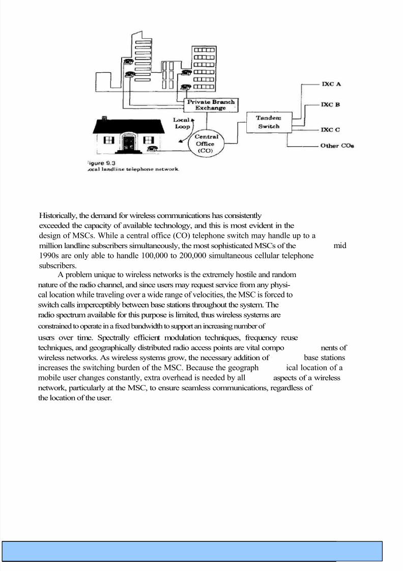
The North American Cellular Network architecture used to provide user traffic and signaling traffic between
MSCs [From [NAC94] © IEEE]. The components of the SS7 network and their applications are described later in this
chapter .
When the user roams into a new market covered by a different service provider, the
wireless network must regis ter the user in the new area and cancel its registration
with the previous service provider so that calls may be routed to the roamer as it
moves through the coverage areas of different MSCs.
Until the early 1990s, U.S. cellular customers that roamed between differ-
ent cellular systems had to register manually each time they entered a new mar-
ket during long distance travel. This required the user to call an operator to
request registration. In the early 1990s, U.S. cellular carriers implemented the
network protocol standard IS-41 to allow different cellular systems to automati-
cally accommodate subscribers who roam into their coverage region. This is called
interoperator roaming . IS-41 allows MSCs of different service providers to
pass information about their subscribers to other MSCs on demand.
IS-41 relies on a feature of AMPS called autonomous registration .
Autono-mous registration is a process by which a mobile notifies a serving MSC of its
presence and location. The mobile accomplishes this by periodically keying up
and transmitting its identity information, which allows the MSC to constantly
update its customer list. The registration command is sent in the overhead mes-
sage of each control channel at five or ten minute intervals, and includes a timer
value which each mobile uses to determine the precise time at which it should
respond to the serving base station with a registration transmission. Each
mobile reports its MIN and ESN during the brief registration transmission so
that the MSC can validate and update the customer list within the market.
The MSC is able to distinguish home users from roaming users based on the MIN
of each active user, and maintains a real-time user list in the home location regis-
ter (HLR) and visitor location register (VLR) as shown in Figure 9.5. IS-41
allows the MSCs of neighboring systems to automatically handle the registration
and location validation of roamers so that users no longer need to manually reg-
ister as they travel. The visited system creates a VLR record for each new
roamer and notifies the home system via IS-41 so it can update its own HLR.

8/3/2019 Wcn Complete 123 Units
http://slidepdf.com/reader/full/wcn-complete-123-units 36/58
b h a r g a v . r 3 2 @ g m a i l . c o mage
✔ Second Generation Wireless Networks
Second generation wireless systems employ digital modulation and
advanced call processing capabilities. Examples of second generation wireless
systems include the Global System for Mobile (GSM), the TDMA and CDMA U.S.
digital standards (the Telecommunications Industry Association IS-54 and IS-95
standards), Second Generation Cordless Telephone (CT2), the British
standard for cordless telephony, the Personal Access Communications System
(PACS) local loop standard, and Digital European Cordless Telephone(DECT), which is the European standard for cordless and office telephony.
Second generation wireless networks have introduced new network archi tectures
that have reduced the computational burden of the MSC. GSM has introduced the
concept of a base station controller (BSC) which is inserted between several
base stations and the MSC. In PACS/WACS, the BSC is called a radio port
control unit. This architectural change has allowed the data interface between the
base station controller and the MSC to be stan dardized, thereby allowing carriers to
use different manufacturers for MSC and BSC components. This trend in
standardization and interoperability is new to second generation wireless networks.Eventually, wireless network components, such as the MSC and BSC, will be
available as off-the-shelf components, much like their wireline telephone
counterparts.
All second generation systems use digital voice coding and digital modula-
tion. The systems employ dedicated control channels (common channel signaling
- see section 9.7) within the air interface for simultaneously exchanging voice
and control information between the subscriber, the base station, and the MSC
while a call is in progress. Second generation systems also provide dedicated
voice and signaling trunks between MSCs, and between each MSC and the
PSTN.In contrast to first generation systems, which were designed primarily for
voice, second generation wireless networks have been specifically designed to
provide paging, and other data services such as facsimile and high-data rate net-
work access. The network controlling structure is more distributed in second
generation wireless systems, since mobile stations assume greater control func-
tions. In second generation wireless networks, the handoff process is mobile-con-
trolled and is known as mobile assisted handoff .
The mobile units in these networks perform several other functions not
per formed by first generation subscriber units, such as received power reporting,
adjacent base station scanning, data encoding, and encryption.
DECT is an example of a second generation cordless telephone standardwhich allows each cordless phone to communicate with any of a number of basestations, by automatically selecting the base station with the greatest signallevel. In DECT, the base stations have greater control in terms of switching, sig-naling, and controlling handoffs. In general, second generation systems have been designed to reduce the computational and switching burden at the base sta-tion or MSC, while providing more flexibility in the channel allocation scheme sothat systems may be deployed rapidly and in a less coordinated manner.

8/3/2019 Wcn Complete 123 Units
http://slidepdf.com/reader/full/wcn-complete-123-units 37/58
b h a r g a v . r 3 2 @ g m a i l . c o mage
Third Generation Wireless Networks
Third generation wireless systems will evolve from mature second genera tion
systems. The aim of third generation wireless networks is to provide a single set of
standards that can meet a wide range of wireless applications and provide universal
access throughout the world. In third generation wireless systems, the distinctions
between cordless telephones and cellular telephones will disappear, and a universal
personal communicator (a personal handset) will provide access to a variety of voice,
data, and video communication services.
Third generation systems will use the Broadband Integrated Services
Digi tal Network (B-ISDN) to provide access to information networks, such as the
Internet and other public and private databases. Third generation networks will carrymany types of information (voice, data, and video), will operate in varied regions
(dense or sparsely populated regions), and will serve both stationary users and
vehicular users traveling at high speeds. Packet radio communications will likely be
used to distribute network control while providing a reliable information transfer .
The terms Personal Communication System (PCS) and Personal
Communi cation Network (PCN) are used to imply emerging third generation wireless
sys tems for hand-held devices. Other names for PCS include Future Public Land
Mobile Telecommunication Systems (FPLMTS) for worldwide use which has
more recently been called International Mobile Telecommunication (IMT-2000),
and Universal Mobile Telecommunication System (UMTS) for advancedmobile personal services in Europe.
4 Fixed Network Transmission Hierarchy
Wireless networks rely heavily on landline connections. For example, the
MSC connects to the PSTN and SS7 networks using fiber optic or copper cable or
microwave links. Base stations within a cellular system are connected to the
MSC using line-of-sight (LOS) microwave links, or copper or fiber optic
cables. These connections require high data rate serial transmission schemes in order to
reduce the number of physical circuits between two points of connection.
Several standard digital signaling (DS) formats form a transmission hierar chy that
allows high data rate digital networks which carry a large number of voice channels to
be interconnected throughout the world. These DS formats use
time division multiplexing (TDM). The most basic DS format in the U.S. is called

8/3/2019 Wcn Complete 123 Units
http://slidepdf.com/reader/full/wcn-complete-123-units 38/58
b h a r g a v . r 3 2 @ g m a i l . c o mage
DS-0, which represents one duplex voice channel which is digitized into a 64
kbps binary PCM format. The next DS format is DS-1, which represents twenty-
four full duplex DS-0 voice channels that are time division multiplexed into a
1.544 Mbps data stream (8 kbps is used for control purposes). Related to digital
transmission hierarchy is the T(N) designation, which is used to denote trans-
mission line compatibility for a particular DS format. DS-1 signaling is used for a Ti trunk, which is a popular point-to-point network signaling format used to
connect base stations to the MSC. T1 trunks digitize and distribute the twenty-
four voice channels onto a simple four-wire full duplex circuit. In Europe, CEPT
(Confe'rence Europe'ene Postes des et Te'le'communication) has defined a simi-
lar digital hierarchy.
Level 0 represents a duplex 64 kbps voice channel, whereas
level 1 concentrates thirty channels into a 2.048 Mbps TDM data stream. Most of
the world's PTI's have adopted the European hierarchy. Table 9.1 illustrates the
digital hierarchy for North America and Europe
Typically, coaxial or fiber optic cable or wideband microwave links are used to
transmit data rates in excess of 10 Mbps, whereas inexpensive wire (twisted pair) or
coaxial cable may be used for slower data transfer. When connecting base stations to
a MSC, or distributing trunked voice channels throughout a wireless network, T1
(DS1) or level 1 links are most commonly used and utilize common-twisted pair wiring.
DS-3 and higher rate circuits are used to connect MSCs and COs to the PSTN.
5 Traffic Routing in Wireless Networks
The amount of traffic capacity required in a wireless network is highly
dependent upon the type of traffic carried. For example, a subscriber's telephonecall (voice traffic) requires dedicated network access to provide real-time commu-
nications, whereas control and signaling traffic may be bursty in nature and may
be able to share network resources with other bursty users. Alternatively, some
traffic may have an urgent delivery schedule while some may have no need to be
sent in real-time. The type of traffic carried by a network determines the routing
services, protocols, and call handling techniques which must be employed.
Two general routing services are provided by networks. These are connec -
tion-oriented services (virtual circuit routing), and connectionlessservices (data-
gram services). In connection-oriented routing, the communications path
between the message source and destination is fixed for the entire duration of
the message, and a call set-up procedure is required to dedicate network

8/3/2019 Wcn Complete 123 Units
http://slidepdf.com/reader/full/wcn-complete-123-units 39/58
b h a r g a v . r 3 2 @ g m a i l . c o mage
resources to both the called and calling parties. Since the path through the net-
work is fixed, the traffic in connection-oriented routing arrives at the receiver in
the exact order it was transmitted. A connection-oriented service relies heavily on
error control coding to provide data protection in case the network connection
becomes noisy. If coding is not sufficient to protect the traffic, the call is broken, and
the entire message must be retransmitted from the beginning.
Connectionless routing, on the other hand, does not establish a firm connec-
tion for the traffic, and instead relies on packet-based transmissions. Several
packets form a message, and each individual packet in a connectionless serviceis routed separately. Successive packets within the same message might travel
completely different routes and encounter widely varying delays throughout the
network.
Packets sent using connectionless routing do not necessarily arrive in
the order of transmission and must to be reordered at the receiver. Because
packets take different routes in a connectionless service, some packets may be
lost due to network or link failure, however others may get through with suffi-
cient redundancy to enable the entire. message to be recreated at the receiver.
Thus, connectionless routing often avoids having to retransmit an entire mes-sage, but requires more overhead information for each packet. Typical packet
overhead information includes the packet source address, the destination
address, the routing information, and information needed to properly order
packets at the receiver. In a connectionless service, a call set-up procedure is
not required at the beginning of a call, and each message burst is treated
independently by the network.

8/3/2019 Wcn Complete 123 Units
http://slidepdf.com/reader/full/wcn-complete-123-units 40/58
b h a r g a v . r 3 2 @ g m a i l . c o mage
1 Circuit Switching
First generation cellular systems provide connection-oriented services for
each voice user. Voice channels are dedicated for users at a serving base station,
and network resources are dedicated to the voice traffic upon initiation of a call.
That is, the MSC dedicates a voice channel connection between the base station
and the PSTN for the duration of a cellular telephone call. Furthermore, a call
initiation sequence is required to connect the called and calling parties on a cel-
lular system. When used in conjunction with radio channels, connection-oriented
services are provided by a technique called circuit switching , since a physical
radio channel is dedicated ("switched in to use") for two-way traffic between the
mobile user and the MSC, and the PSTN dedicates a voice circuit between the
MSC and the end-user. As calls are initiated and completed, different radio cir-
cuits and dedicated PSTN voice circuits are switched in and out to handle the
traffic.
Circuit switching establishes a dedicated connection (a radio channel
between the base and mobile, and a dedicated phone line between the MSC and the
PSTN) for the entire duration of a call. Despite the fact that a mobile user may handoff to different base stations, there is always a dedicated radio channel to provide service
to the user, and the MSC dedicates a fixed, full duplex phone connection to the PSTN.
Wireless data networks are not well supported by circuit switching, due to
their short, bursty transmissions which are often followed by periods of inactiv-
ity. Often, the time required to establish a circuit exceeds the duration of the
data transmission. Circuit switching is best suited for dedicated voice-only traf-
f i c, or for instances where data is continuously sent over long periods of time.
2. Packet Switching Connectionless services exploit the fact that dedicated resources are not
required for message transmission. Packet switching (also called virtual switch-
ing) is the most common technique used to implement connectionless services
and allows a large number of data users to remain virtually connected to the
same physical channel in the network. Since all users may access the network
randomly and at will, call set-up procedures are not needed to dedicate specific
circuits when a particular user needs to send data. Packet switching breaks each
message into smaller units for transmission and recovery .
When a message is broken into packets, a certain amount of control information isadded to each packet to provide source and destination identification, as well as error
recovery provisions.
Figure 9.7 illustrates the sequential format of a packet transmission . The packetconsists of header information, the user data, and a trailer. The header specifies the
beginning of a new packet and contains the source address, destina tion address, packetsequence number, and other routing and billing informa tion. The user data containsinformation which is generally protected with error control coding. The trailer contains acyclic redundancy checksum which is used for error detection at the receiver.

8/3/2019 Wcn Complete 123 Units
http://slidepdf.com/reader/full/wcn-complete-123-units 41/58
b h a r g a v . r 3 2 @ g m a i l . c o mage
Figure 9.7 Packet data format .
Figure 9.8 shows the structure of a transmitted packet, which typically con-
sists of five fields: the flag bits, the address field, the control field, the informa-
tion field, and the frame check sequence field. The flag bits are specific (or
reserved) bit sequences that indicate the beginning and end of each packet. The
address field contains the source and the destination address for transmitting
messages and for receiving acknowledgments. The control field defines functions
such as transfer of acknowledgments, automatic repeat requests (ARQ), and
packet sequencing. The information field contains the user data and may have
variable length. The final field is the frame check sequence field or the CRC
(Cyclic Redundancy Check) that is used for error detection.
Figure 9.8 Fields in a typical packet of data.
In contrast to circuit switching, packet switching (also called packet radio
when used over a wireless link) provides excellent channel efficiency for bursty
data transmissions of short length. An advantage of packet-switched data is that
the channel is utilized only when sending or receiving bursts of information.
This benefit is valuable for the case of mobile services where the available band-
width is limited. The packet radio approach supports intelligent protocols for
data flow control and retransmission, which can provide highly reliable transfer
in degraded channel conditions. X.25 is a widely used packet radio protocol that
defines a data interface for packet switching.

8/3/2019 Wcn Complete 123 Units
http://slidepdf.com/reader/full/wcn-complete-123-units 42/58
b h a r g a v . r 3 2 @ g m a i l . c o mage
Disadvantages of packet switching
The X.25 Protocol
X.25 was developed by CCITT (now ITU-T) to provide standard connection lessnetwork access (packet switching) protocols for the three lowest layers lay ers 1, 2, and 3)
of the open systems interconnection (OSI) model (see Figure 9.14 for the OSI
layer hierarchy). The X.25 protocols provide a standard network interface between
originating and terminating subscriber equipment (called data terminal
equipment or DTE), the base stations (called data circuit-terminat ing
equipment or DCE), and the MSC (called the data switching exchange or
DSE). The X.25 protocols are used in many packet radio air-interfaces, as well as in fixed
networks The X.25 protocol does not specify particular data rates or how
packet switched networks are implemented.
Figure 9.9 shows the hierarchy of X.25 protocols in the OSI model. The
Layer 1 protocol deals with the electrical, mechanical, procedural, and functional
interface between the subscriber (DTE), and the base station (DCE). The Layer 2
protocol defines the data link on the common air-interface between the sub-
scriber and the base station. Layer 3 provides connection between the base sta-
tion and the MSC, and is called the packet layer protocol . A packet assembler
disassembler ( PAD ) is used at Layer 3 to connect networks using the X.25 inter-
face with devices that are not equipped with a standard X.25 interface.
Figure 9.9 Hierarchy of X.25 in OSI model

8/3/2019 Wcn Complete 123 Units
http://slidepdf.com/reader/full/wcn-complete-123-units 43/58
b h a r g a v . r 3 2 @ g m a i l . c o mage

8/3/2019 Wcn Complete 123 Units
http://slidepdf.com/reader/full/wcn-complete-123-units 44/58
b h a r g a v . r 3 2 @ g m a i l . c o mage
UNIT-3
Wireless Data Services
• Circuit switching is inefficient for dedicated mobile data services such as
facsimile (fax), electronic mail (e-mail), and short messaging.
• First generation cellular systems that provide data communications using circuit
switching have difficulty passing modem signals through the audio filters of
receivers designed for analog, FM, common air-interfaces.
• voice filtering must be deactivated when data is transmitted over first
genera tion cellular networks, and a dedicate d data link must be established
over the common air-interface.
• The demand for packet data services has, until recently,
been significantly less than the demand for voice services, and first generation
subscriber equipment design has focused almost solely on voice-only cellular
communications.• However, in 1993, the U.S. cellular industry developed the cel lular digital packet
data (CDPD) standard to coexist with the conventional voice-
only cellular system.
• In the 1980s, two other data-only mobile services called ARDIS and RMD
were developed to provide pac ket radio connectivity through- out a network.
1 Cellular Digital Packet Data (CDPD)
CDPD is a data service for first and second generation U.S. cellular systems and
uses a full 30 kHz AMPS channel on a shared basis. CDPD provides mobile packet data
connectivity to existing data networks and other cel lular systems without any
additional bandwidth requirements. It also capital izes on the unused air time which
occurs between successive radio channel assignments by the MSC (it is estimated
that for 30% of the time, a particular cellular radio channel is unused, so packet data
may be transmitted until that channel is selected by the MSC to provide a voice
circuit).
CDPD directly overlays with existing cellular infrastructure and uses exist-
ing base station equipment, making it simple and inexpensive to install. Fur-
thermore CDPD does not use the MSC, but rather has its own traffic routing
capabilities. CDPD occupies voice channels purely on a secondary, noninterfering basis, and packet channels are dynamically assigned (hopped) to different cellu-
lar voice channels as they become vacant, so the CDPD radio channel varies with
time.
As with conventional, first generation AMPS, each CDPD channel is duplex
in nature. The forward channel serves as a beacon and transmits data from the
PSTN side of the network, while the reverse channel links all mobile users to the
CDPD network and serves as the access channel for each subscriber. Collisions
may result when many mobile users attempt to access the network simulta-
neously.

8/3/2019 Wcn Complete 123 Units
http://slidepdf.com/reader/full/wcn-complete-123-units 45/58
b h a r g a v . r 3 2 @ g m a i l . c o mage
Each CDPD simplex link occupies a 30 kHz RF channel, and data is
sent at 19,200 bps. Since CDPD is packet-switched, a large number of modems
are able to access the same channel on an as needed, packet-by-packet basis.
CDPD supports broadcast, dispatch, electronic mail, and field monitoring appli
cations. GMSK BT=0.5 modulation is used so that existing analog FM cellular
receivers can easily detect the CDPD format without redesign.
CDPD transmissions are carried out using fixed-length blocks. User data is
protected using a Reed Solomon (63,47) block code with 6-bit symbols. For each packet,
282 user bits are coded into 378 bit blocks, which provide correction for up to eight
symbols.
Two lower layer protocols are used in CDPD. The mobile data link protocol
(MDLP) is used to convey information between data link layer entities (layer 2
devices) across the CDPD air interface. The MDLP provides logical data link con-
nections on a radio channel by using an address contained in each packet frame.
The MDLP also provides sequence control to maintain the sequential order of frames across a data link connection, as well as error detection and flow control.
The Radio Resource Management P rotocol (RRMP) is a
higher, layer 3 protocol used to manage the radio channel resources of the CDPD system
and enables an M-ES to find and utilize a duplex radio channel without interfering
with stan dard voice services, The RRMP handles base-station identification and
configu ration messages for all M-ES stations, and provides information that the M-ES
can use to determine usable CDPD channels without knowledge of the history of channel
usage. The RRMP also handles channel hopping commands, cell hand- offs, and M-ES
change of power commands. CDPD version 1.0 uses the X.25 wide area network
(WAN) subprofile and frame relay capabilities for internal subnetworks.
Table 9.2 lists the link layer characteristics for CDPD. Figure 9.10 illus trates a
typical CDPD network. Note that the subscribers (the mobile end sys tem, or M-
ES) are able to connect through the mobile data base stations (MDBS) to the
Internet via intermediate systems (MD-IS), which act as servers and rout ers for
the subscribers. In this way, mobile users are able to connect to the Inter net or the
PSTN. Through the I-interface, CDPD can carry either Internet protocol (IP) or
OSI connectionless protocol(CLNP)traffic.
8/3/2019 Wcn Complete 123 Units
http://slidepdf.com/reader/full/wcn-complete-123-units 46/58
b h a r g a v . r 3 2 @ g m a i l . c o mage
M-ES :Mobile End StationMDBS Mobile Data Base Station
MD-IS Intermediate Server for CDPD traffic
Figure 9.10 The CDPD network .
2 Advanced Radio Data Information Systems (ARDIS)
Advance Radio Data Information Systems (ARDIS) is a private
network
service provided by Motorola and IBM and is based on MDC 4800 and RD-LAP
(Radio Data Link Access Procedure) protocols developed at Motorola [DeR94].
ARDIS provides 800 MHz two-way mobile data communications for short-length
radio messages in urban and in-building environments, and for users traveling
at low speeds. Short ARDIS messages have low retry rates but high packet over-
head, while long messages spread the overhead over the length of the packet but
have a higher retry rate. ARDIS has been deployed to provide excellent in-build-
ing penetration, and large-scale spatial antenna diversity is used to receive mes-
sages from mobile users. When a mobile sends a packet, many base stations
which are tuned to the transmission frequency attempt to detect and decode the
transmission, in order to provide diversity reception for the case when multiple
mobiles contend for the reverse link. In this manner, ARDIS base stations are
able to insure detection of simultaneous transmissions, as long as the users are
sufficiently separated in space. Table 9.3 lists some characteristics for ARDIS.
3. RAM Mobile Data (RMD)
RAM Mobile Data (RMD) is a public, two-way data service based upon the
Mobitex protocol developed by Ericsson. RAM provides street level coverage for
short and long messages for users moving in an urban environment. RAM has

8/3/2019 Wcn Complete 123 Units
http://slidepdf.com/reader/full/wcn-complete-123-units 47/58
b h a r g a v . r 3 2 @ g m a i l . c o mage
capability for voice and data transmission, but has been designed primarily for
data and facsimile. Fax messages are transmitted as normal text to a gateway
processor, which then converts the radio message to an appropriate format by
merging it with a background page. Thus, the packet-switched wireless trans-
mission consists of a normal length message instead of a much larger fax image,
even though the end-user receives what appears to be a standard fax [DeR94].
some characteristics of the RAM mobile data service.
Channel Characteristics for RAM Mobile Data
Protocol Mobitex
Speed (bps) 8000
Channel Bandwidth (kHz) 12.5
Spectrum Efficiency (b/Hz) 0.64
Random Error Strategy 12, 8 Hamming code
Burst Error Strategy interleave 21 bits
Fading Performance withstands 2.6 ms fade
Channel Access slotted CSMA
4.Common Channel Signaling (CCS)Common channel signaling (CCS) is a digital communications
technique
that provides simultaneous transmission of user data, signaling data, and other
related traffic throughout a network. This is accomplished by using out -of-- band
signaling channels which logically separate the network data from the user
information (voice or data) on the same channel. For second generation wirelesscommunications systems, CCS is used to pass user data and control/supervisory
signals between the subscriber and the base station, between the base station
and the MSC, and between MSCs. Even though the concept of CCS implies dedi-
cated, parallel channels, it is implemented in a TDM format for serial data
transmissions.
Before the introduction of CCS in the 1980s, signaling traffic between theMSC and a subscriber was carried in the same band as the end-user's audio. Thenetwork control data passed between MSCs in the PSTN was also carried in band,requiring that network information be carried within the same channel as the
subscriber's voice traffic throughout the PSTN. This technique, called in bandsignaling, reduced the capacity of the PSTN, since the network signaling data
rates were greatly constrained by the limitations of the carried voice channels, andthe PSTN was forced to sequentially (not simultaneously) handle signaling and user data for each call.

8/3/2019 Wcn Complete 123 Units
http://slidepdf.com/reader/full/wcn-complete-123-units 48/58
b h a r g a v . r 3 2 @ g m a i l . c o mage
CCS is an out-of-band signaling technique which allows much faster com-
munications between two nodes within the PSTN. Instead of being constrained
to signaling data rates which are on the order of audio frequencies, CCS supports
signaling data rates from 56 kbps to many megabits per second. Thus, network
signaling data is carried in a seemingly parallel, out-of-band, signaling channel
while only user data is carried on the PSTN. CCS provides a substantial increase
in the number of users which are served by trunked PSTN lines, but requiresthat a dedicated portion of the trunk time be used to provide a signaling channel
used for network traffic. In first generation cellular systems, the SS7 family of
protocols, as defined by the Integrated System Digital Network (ISDN) are used
to provide CCS.
Since network signaling traffic is bursty and of short duration, the signal-
ing channel may be operated in a connectionless fashion where packet data
transfer techniques are efficiently used. CCS generally uses variable length
packet sizes and a layered protocol structure. The expense of a parallel signaling
channel is minor compared to the capacity improvement offered by CCS through-out the PSTN, and often the same physical network connection (i.e., a fiber optic
cable) carries both the user traffic and the network signaling data.
4.1. The Distributed Central Switching Office for CCS
As more users subscribe to wireless services, backbone networks that link
MSCs together will rely more heavily on network signaling to preserve message
integrity, to provide end-to-end connectivity for each mobile user, and to main tain a
robust network that can recover from failures. CCS forms the foundation of network
control and management functions in second and third generation networks. Out-of-band signaling networks which connect MSCs throughout the world enable the
entire wireless network to update and keep track of specific mobile users, wherever
they happen to be. Figure 9.6 illustrates how an MSC is connected to both the PSTN
and the signaling network.
As shown in Figure 9.11, the CCS network architecture is composed of geo-
graphically distributed central switching offices, each with embedded switching
end points (SEPs), signaling transfer points (STPs), a service
management system (SMS), and a database service management
system (DBAS)

8/3/2019 Wcn Complete 123 Units
http://slidepdf.com/reader/full/wcn-complete-123-units 49/58
b h a r g a v . r 3 2 @ g m a i l . c o mage
SEPs: Switching End PointsSTPs: Signaling Transfer PointsSMS: Service Management SystemSS7: Signaling System No. 7
Figure 9.11
Common channel signaling (CCS) network architecture showing STPs, SEPs, and SMS embedded
within a central switching office, based on SS7.
The MSC provides subscriber access to the PSTN via the SEP. The SEP
implements a stored-program-control switching system known as the service
control point (SCP) that uses CCS to set up calls and to access a network data base. The SCP instructs the SEP to create billing records based on the call
information recorded by the SCP.
The STP controls the switching of messages between nodes in the CCS net work.
For higher reliability of transmission (redundancy), SEPs are required to be
connected to the SS7 network (described in Section 9.8) via at least two STPs. This
combination of two STPs in parallel is known as a mated pair , and provides
connectivity to the network in the event one STP fails.
The SMS contains all subscriber records, and also houses toll-free data-
bases which may be accessed by the subscribers. The DBAS is the administrative
database that maintains service records and investigates fraud throughout the network.
The SMS and DBAS work in tandem to provide a wide range of customer and
network provider services, based on SS7.
8/3/2019 Wcn Complete 123 Units
http://slidepdf.com/reader/full/wcn-complete-123-units 50/58
b h a r g a v . r 3 2 @ g m a i l . c o mage
5 .Integrated Services Digital Network (ISDN)
Integrated Services Digital Network (ISDN) is a complete network
frame-
work designed around the concept of common channel signaling. While tele-
phone users throughout the world rely on the PSTN to carry conventional voice
traffic, new end-user data and signaling services can be provided with a parallel,
dedicated signaling network. ISDN defines the dedicated signaling network that
has been created to complement the PSTN for more flexible and efficient network
access and signaling and may be thought of as a parallel world-wide
network for signaling traffic that can be used to either route voice traffic on the
PSTN or to provide new data services between network nodes and the end-users.
ISDN provides two distinct kinds of signaling components to end-users in a
telecommunications network. The first component supports traffic between the
end-user and the network, and is called Access signaling . Access signaling
defines how end-users obtain access to the PSTN and the ISDN for communica-tions or services, and is governed by a suite of protocols known as the Digital
Subscriber Signaling System number 1(DSS1). The second signaling
component
of ISDN is network signaling, and is governed by the SS7 suite of protocols
.For wireless communications systems, the SS7 protocols within ISDN
are critical to providing backbone network connectivity between MSCs through-
out the world, as they provide network interfaces for common channel signaling
traffic.
ISDN provides a complete digital interface between end-users over twisted pair
telephone lines. The ISDN interface is divided into three different types of channels.Information bearing channels called bearer channels (B channels) are used
exclusively for end-user traffic (voice, data, video). Out-of-band signaling channels,
called data channels (D channels), are used to send signaling and con trol
information across the interface to end-users. As shown in Figure 9.12, ISDN
provides integrated end-user access to both circuit-switched and
packetswitched networks with digital end-to-end connectivity.
ISDN end-users may select between two different interfaces, the Basic rate
interface (BRI) or the primary rate interface (PRI). The BRI is intended to
serve
small capacity terminals (such as single line telephones) while the PRI is intended for
large capacity terminals (such as PBXs). The B channels support 64
kbps data for both the primary rate and the basic rate interfaces. The D channel
supports 64 kbps for the primary rate and 16 kbps for the basic rate. The BRI
provides two 64 kbps bearer channels and one 16 kbps signaling channel (2B+D),
whereas the PRI provides twenty-three 64 kbps bearer channels and one 64 kbps
signaling channel (23B+D) for North America and Japan. In Europe, the pri-
mary rate interface provides thirty basic information channels and one 64 kbps
signaling channel (30B+D). The PRI service is designed to be carried by DS-1 or
CEPT level 1 links .

8/3/2019 Wcn Complete 123 Units
http://slidepdf.com/reader/full/wcn-complete-123-units 51/58
b h a r g a v . r 3 2 @ g m a i l . c o mage
Figure 9.12 Block diagram of an Integrated Services Digital
Network
Even though the diagram illustrates par allel channels, the TDM-based serial data structure uses a
single twisted pair.
For wireless service subscribers, an ISDN basic rate interface is
provided in exactly the same manner as for a fixed terminal. To differentiate
between wire less and fixed subscribers, the mobile BRI defines signaling data
(D channels in the fixed network) as control channels (C channels in the
mobile network), so that a wireless subscriber has 2B+C service.
Much like the digital signaling hierarchy described in Section 9.2,
several ISDN circuits may be concatenated into high speed information
channels (H channels). H channels are used by the ISDN backbone to provide
efficient data transport of many users on a single physical connection, and may
also be used by PRI end-users to allocate higher transmission rates on
demand. ISDN defines HO channels (384 kbps), H11 (1536 kbps), and H12
channels (1920 kbps) as shown in Table 9.5

8/3/2019 Wcn Complete 123 Units
http://slidepdf.com/reader/full/wcn-complete-123-units 52/58
b h a r g a v . r 3 2 @ g m a i l . c o mage
5.1 .Broadband ISDN and ATM
With the proliferation of computer systems and video imaging, end-user
applications are requiring much greater bandwidths than the standard 64 kbps
B channel provided by ISDN. Recent work has defined ISDN interface standards
that increase the end-user transmission bandwidth to several Mb's. This emerging
networking technique is known as broadband ISDN (B-ISDN) and is based on
asynchronous transfer mode (ATM) technology which allows packet switching
rates up to 2.4 Gbps and total switching capacities as high as 100 Gbps .
ATM is a packet switching and multiplexing technique which has been spe-
cifically designed to handle both voice users and packet data users in a single
physical channel. ATM data rates vary from low traffic rates (64 kbps) over twisted
pair to over 100 Mbps over fiber optic cables for high traffic rates between network
nodes. ATM supports bidirectional transfer of data packets of fixed length
between two end points, while preserving the order of transmission. ATM data units,
called cells, are routed based on header information in each unit (called a
label) that identifies the cell as belonging to a specific ATM virtual con nection.
The label is determined upon virtual connection of a user, and remains the
same throughout the transmission for a particular connection. The ATM header
also includes data for congestion control, priority information for queuing of packets,
and a priority which indicates which ATM packets can be dropped in case of
congestion in the network,
Figure 9.13 shows the cell format of ATM. ATM cells (packets) have a fixed
length of 53 bytes, consisting of 48 bytes of data and 5 bytes of header informa-
tion. Fixed length packets result in simple implementation of fast packet
switches, since packets arrive synchronously at the switch. A compro-
mise was made in selecting the length of ATM cells to accommodate both voiceand data users.
Figure 9.13 Cell format of Asynchronous Transfer Mode (ATM).
6. Signaling System No. 7 (SS7)
The SS7 signaling protocol is widely used for common channel signaling
between interconnected networks (see Figure 9.11, for example). SS7 is used to
interconnect most of the cellular MSCs throughout the U.S., and is the key factor
in enabling autonomous registration and automated roaming in first generation cellular
systems.

8/3/2019 Wcn Complete 123 Units
http://slidepdf.com/reader/full/wcn-complete-123-units 53/58
b h a r g a v . r 3 2 @ g m a i l . c o mage
SS7 is an outgrowth of the out-of band signaling first developed by the
CCITT under common channel signaling standard, CCS No. 6. Further
work caused SS7 to evolve along the lines of the ISO-OSI seven layer network
definition, where a highly layered structure (transparent from layer to layer) is used to
provide network communications. Peer layers in the ISO model communicate with
each other through a virtual (packet data) interface, and a hierarchical interface
structure is established. A comparison of the OSI-7 network model and the SS7 protocol standard is given in Figure 9.14. The lowest three layers of the OSI model
are handled in SS7 by the network service part (NSP) of the protocol, which in
turn is made up of three message transfer parts (MTPs) and the signal ing
connection control part (SCCP) of the SS7 protocol.
OMAP: Operations Maintenance and Administration Part
ASE: App}ication Service Element
TCAP: Transaction Capabilities Application Part
SCCP: Signaling Connection Control Part
MTP: Message Transfer Part
NSP: Network Service Part
Figure 9.14 SS7 protocol architectur e
6.1 Network Services Part (NSP) of SS7
The NSP provides ISDN nodes with a highly reliable and efficient means of
exchanging signaling traffic using connectionless services. The SCCP
in SS7 actually supports packet data network interconnections as well as
connection oriented networking to virtual circuit networks. The NSP allows
network nodes to communicate throughout the world without concern for the
application or context of the signaling traffic.
6.1.1 Message Transfer Part (MTP) of SS7
The function of the MTP is to ensure that signaling traffic can be trans ferred
and delivered reliably between the end-users and the network. MTP is provided at
three levels. Figure 9.15 shows the functionality of the various MTP levels that will bedescribed.

8/3/2019 Wcn Complete 123 Units
http://slidepdf.com/reader/full/wcn-complete-123-units 54/58
b h a r g a v . r 3 2 @ g m a i l . c o mage
Signaling data link functions (MTP Level 1) provide an interface to
the actual physical channel over which communication takes place. Physical chan nels
may include copper wire, twisted pair, fiber, mobile radio, or satellitelinks, and are
transparent to the higher layers. CCITT recommends that MTPLevel 1
use 64 kbps transmissions, whereas ANSI recommends 56 kbps. The minimum
data rate provided for telephony contro l operations is 4.8 kbps .
Figure 9.15 Functional diagram of message transfer part
Signaling link functions (MTP Level 2) correspond to the second
layer in
the OSI reference model and provide a reliable link for the transfer of traffic
between two directly connected signaling points. Variable length packet mes-
sages, called message signal units (MSUs), are defined in MTP Level 2. A singleMSU cannot have a packet length which exceeds 272 octets, and a standard: 16
bit cyclic redundancy check (CRC) checksum is included in each MSU for error
detection. A wide range of error detection and correction features are provided in
MTP Level 2.
MTP Level 2 also provides flow control data between two signaling points
as a means of sensing link failure. If the receiving device does not respond to
data transmissions, MTP Level 2 uses a timer to detect link failure, and notifies
the higher levels of the SS7 protocol which take appropriate actions to reconnect the
link. Signaling network functions (MTP Level 3) provide procedures that transfer
messages between signaling nodes. As in ISDN, there are two types of MTP Level 3
functions: signaling message handling and signaling network manage ment. Signaling
message handling is used to provide routing, distribution, and traffic discrimination
(discrimination is the process by which a signaling point determines whether or not a
packet data message is intended for its use or not). Signaling network management
allows the network to reconfigure in case of node failures, and has provisions to
allocate alternate routing facilities in the case of congestion or blockage in parts of
the network .

8/3/2019 Wcn Complete 123 Units
http://slidepdf.com/reader/full/wcn-complete-123-units 55/58
b h a r g a v . r 3 2 @ g m a i l . c o mage
6.1.2 Signaling Connection Control Part (SCCP) of SS7
The signaling connection control part (SCCP) provides enhancement to the
addressing capabilities provided by the MTP. While the addressing capabilities of MTP
are limited in nature, SCCP uses local addressing based on subsystem numbers (SSNs)
to identify users at a signaling node. SCCP also provides the ability to address global
title messages, such as 800 numbers or non billed numbers. SCCP provides four classes of
service: two are connectionless and two are connection-oriented, as shown in Table 9.6.
Table 9.6 Different Classes of Service Provided by SCCP
Class of Se rvice Type of Service
Class 0 Basic connection class
Class 1 Sequenced (MTP) connectionless class
Class 2 Basic connection-o riented class
Class 3 Flow control connection-o riented class
SCCP consists of four functional blocks. The SCCP connection-oriented control
block provides data transfer on signaling connections. The SCCP man agement block
provides functions to handle congestion and failure conditions that cannot be
handled at the MTP. The SCCP routing block routes forwards messages received
from MTP or other functional blocks.
7. The SS7 User Part
As shown in Figure 9.14, the SS7 user part provides call control and man-
agement functions and call set-up capabilities to the network. These are the
higher layers in the SS7 reference model, and utilize the transport facilities pro-
vided by the MTP and the SCCP. The SS7 user part includes the ISDN user part
(ISUP), the transactul7, capabilities application part (TCAP) and the
operations maintenance and administration part (OMAP). The
telephone User part (TUP) and. the data user part (DUP) are included in the
ISUP.
7.1. Integrated Services Digital Network User Part (ISUP)
The ISUP provides the signaling functions for carrier and supplementary
services for voice, data, and video in an ISDN environment. In the past, tele- phony requirements were lumped in the TUP, but this is now a subset of ISUP.
ISUP uses the MTP for transfer of messages between different exchanges. ISUP
message includes a routing label that indicates the source and destination of the
message, a circuit identification code (CIC), and a message code that serves to
define the format and function of each message. They have variable lengths with
a maximum of 272 octets that includes MTP level headers. In addition to the
basic bearer services in an ISDN environment, the facilities of user-to-user sig-
naling, closed user groups, calling line identification, and call forwarding are
provided.

8/3/2019 Wcn Complete 123 Units
http://slidepdf.com/reader/full/wcn-complete-123-units 56/58
b h a r g a v . r 3 2 @ g m a i l . c o mage
7.2. Transaction Capabilities Application Part (TCAP)
The transaction capabilities application part in SS7 refers to the applica tion layer
which invokes the services of the SCCP and the MTP in a hierarchical format. One
application at a node is thus able to execute an application at another node and use
these results. Thus, TCAP is concerned with remote operations. TCAP messages are used
by IS-41.
7. 3 Operation Maintenance and Administration Part (OMAP)
The OMAP functions include monitoring, coordination, and control func tions to
ensure that trouble free communications are possible. OMAP supports diagnostics are
known throughout the global network to determine loading and specific subnetwork
behaviors.
8. Signaling Traffic in SS7
Call set-ups, inter-MSC handoffs, and location updates are the main activi-ties that generate the maximum signaling traffic in a network, and which are all
handled under SS7. Setting up of a call requires exchange of information about
the location of the calling subscriber (call origination, calling-party procedures)
and information about the location of the called subscriber. Either or both, of the
calling and the called subscribers can be mobile, and whenever any of the mobile
subscribers switches MSCs under a handoff condition, it adds to the amount of
information exchanged. Table 9.7 shows the amount of signaling traffic that is
generated for call set-up in GSM [Mei93). Location update records are updated in the
network whenever a subscriber moves to a new location. The traffic required by
the location update process as a subscriber moves within and between VLR
areas is shown in Table 9.8.

8/3/2019 Wcn Complete 123 Units
http://slidepdf.com/reader/full/wcn-complete-123-units 57/58
b h a r g a v . r 3 2 @ g m a i l . c o mage
SS7 Services
There are three main type of services offered by the SS7 network [Boy90]:
the Tbuchstar, 800 services, and alternate billing services. These services are brieflyexplained below.
Touchstar - This kind of service is also known as CLASS and is a group of
switch-controlled services that provide its users with certain call management
capabilities. Services such as call return, call forwarding, repeat dialing, call block,
call tracing, and caller ID are provided.
800 services - These services were introduced by Bell System to provide toll-
free access to the calling party to the services and database which is offered by the
private parties. The costs associated with the processing of calls is paid by the service
subscriber. The service is offered under two plans known as the 800-
NXX plan, and the 800 Database plan. In the 800-NXX plan the first six digits of an 800call are used to select the interexcha nge carrier (IXC). In the 800 Data base plan,
the call is looked up in a database to determine the appropriate carrier and routing
information.
Alternate Billing Service and Line Information Database (ADB/
LIDB) - These services use the CCS network to enable the calling
party to bill a call to a personal number (third party number, calling card, or collect
etc.) from any number.
Performance of SS7
The performance of the signaling network is studied by connection set-up
time (response time) or the end-to-end signaling information transfer time. The
delays in the signaling point (SP) and the STP depend on the specific hardware
configuration and switching software implementation. The maximum limits for
these delay times have been specified in the CCI TT recommendations.

8/3/2019 Wcn Complete 123 Units
http://slidepdf.com/reader/full/wcn-complete-123-units 58/58
Congestion Control in SS7 networks - With an increasing number of
subscribers, it becomes important to avoid congestion in the signaling network
under heavy traffic conditions [Mod92], [Man93]. SS7 networking protocols pro-
vide several congestion control schemes, allowing traffic to avoid failed links and
nodes.
Advantages of Common Channel Signaling over
Conventional Sig naling :
• Faster Call Set-up
In CCS, high speed signaling networks are used for
transferring the call set-up messages resulting in smaller delay times when
compared to conventional signaling methods, such as Multi-frequency.
• Greater trunking (or Queueing) Efficiency
CCS has shorter call set-up and tear down times that result in less call-holding time,
subsequently reducing the traffic on the network. In heavy traffic conditions, high
trunking efficiency is obtained.
• Information Transfer –
CCS allows the transfer of additional information along with the signaling traffic
providing facilities such as caller identification and voice or data identification.