Wave Propagation Through Soft Tissue: Effect of Material ...
8
WAVE PROPAGATION THROUGH SOFT TISSUE: EFFECT OF MATERIAL NONLINEARITY AND NONUNIFORM CROSS–SECTION Marcelo F. Valdez * Department of Mechanical Engineering University of Maryland College Park, Maryland 20742 E-mail: [email protected] Balakumar Balachandran Minta Martin Professor Department of Mechanical Engineering University of Maryland College Park, Maryland 20742 E-mail: [email protected] ABSTRACT A better understanding of the influence of material nonlin- earities on the propagation of mechanical stress waves is neces- sary to generate insights into damage mechanisms of soft tissues subjected to rapid and strong external excitations. In this effort, the authors study the propagation of longitudinal stress waves through soft tissue. Emphasis is placed on the influence of non- linear material behavior and nonuniform cross–section on the characteristics of the stress–wave propagation. The mechani- cal behavior of the soft tissue is represented by a nonlinear vis- coelastic model that is obtained through a maximum dissipation, thermodynamically consistent construction. The effect of the tis- sue nonlinear mechanical behavior is studied through asymptotic analysis. Examining the obtained analytical approximation, it is possible to discern nonlinear wave front steepening and the effect of the material dissipation. The effects of a nonuniform cross–sectional area are investigated through numerical simula- tions. These studies can be applied to understand the effect of geometric features of axons on the propagation of longitudinal stress waves. For example, the diameter of an axon gradually in- creases near its ends, and varicosities/boutons along the axons represent concentrated cross–sectional area variations. Simula- tions are carried out to examine various aspects of the nonlinear wave propagation such as wave front steepening. This work can serve as a basis for better understanding the mechanical causes underlying mild traumatic brain injury caused by a head impact or explosive blast waves. * Address all correspondence to this author. NOMENCLATURE X , ξ Dimensional and nondimensional spatial variables t , τ Dimensional and nondimensional times P, P * Dimensional and nondimensional components of the first Piola–Kirchhoff stress tensor ρ 0 Material density in the reference configuration u, v Dimensional and nondimensional axial displacements λ Axial stretch κ Relaxation constant Ψ Uniaxial, incompressible hyperelastic strain energy function A (X ), A * (ξ ) Dimensional and nondimensional cross– sectional areas f (λ ), g (λ ) Dimensional stretch functions f * (λ ), g * (λ ) Nondimensional stretch functions T d Characteristic dissipation time α Nondimensional dissipation constant c 0 Phase speed of elastic longitudinal waves L Characteristic rod length μ n Coefficients in the Taylor expansions of f (λ ) and g (λ ) μ * n Nondimensional version of μ n ε Small parameter ϑ Rescaled damping parameter μ (τ ) Rescaled input displacement amplitude X 0 , T 0 Fast spatial and time scales s 1 , s 2 Fast phase scales T 1 Slow time scales ˇ v n Terms of an asymptotic expansion solution ˇ F n , ˇ G n Solutions of the linear wave equation Proceedings of the ASME 2014 International Mechanical Engineering Congress and Exposition IMECE2014 November 14-20, 2014, Montreal, Quebec, Canada IMECE2014-38953 1 Copyright © 2014 by ASME
Transcript of Wave Propagation Through Soft Tissue: Effect of Material ...

WAVE PROPAGATION THROUGH SOFT TISSUE: EFFECT OF MATERIALNONLINEARITY AND NONUNIFORM CROSS–SECTION
Marcelo F. Valdez∗Department of Mechanical Engineering
University of MarylandCollege Park, Maryland 20742
E-mail: [email protected]
Balakumar BalachandranMinta Martin Professor
Department of Mechanical EngineeringUniversity of Maryland
College Park, Maryland 20742E-mail: [email protected]
ABSTRACTA better understanding of the influence of material nonlin-
earities on the propagation of mechanical stress waves is neces-sary to generate insights into damage mechanisms of soft tissuessubjected to rapid and strong external excitations. In this effort,the authors study the propagation of longitudinal stress wavesthrough soft tissue. Emphasis is placed on the influence of non-linear material behavior and nonuniform cross–section on thecharacteristics of the stress–wave propagation. The mechani-cal behavior of the soft tissue is represented by a nonlinear vis-coelastic model that is obtained through a maximum dissipation,thermodynamically consistent construction. The effect of the tis-sue nonlinear mechanical behavior is studied through asymptoticanalysis. Examining the obtained analytical approximation, itis possible to discern nonlinear wave front steepening and theeffect of the material dissipation. The effects of a nonuniformcross–sectional area are investigated through numerical simula-tions. These studies can be applied to understand the effect ofgeometric features of axons on the propagation of longitudinalstress waves. For example, the diameter of an axon gradually in-creases near its ends, and varicosities/boutons along the axonsrepresent concentrated cross–sectional area variations. Simula-tions are carried out to examine various aspects of the nonlinearwave propagation such as wave front steepening. This work canserve as a basis for better understanding the mechanical causesunderlying mild traumatic brain injury caused by a head impactor explosive blast waves.
∗Address all correspondence to this author.
NOMENCLATUREX , ξ Dimensional and nondimensional spatial variablest, τ Dimensional and nondimensional timesP, P∗ Dimensional and nondimensional components of the first
Piola–Kirchhoff stress tensorρ0 Material density in the reference configurationu, v Dimensional and nondimensional axial displacementsλ Axial stretchκ Relaxation constantΨ Uniaxial, incompressible hyperelastic strain energy functionA (X), A ∗ (ξ ) Dimensional and nondimensional cross–
sectional areasf (λ ), g(λ ) Dimensional stretch functionsf ∗ (λ ), g∗ (λ ) Nondimensional stretch functionsTd Characteristic dissipation timeα Nondimensional dissipation constantc0 Phase speed of elastic longitudinal wavesL Characteristic rod lengthµn Coefficients in the Taylor expansions of f (λ ) and g(λ )µ∗n Nondimensional version of µnε Small parameterϑ Rescaled damping parameterµ (τ) Rescaled input displacement amplitudeX0, T0 Fast spatial and time scaless1, s2 Fast phase scalesT1 Slow time scalesvn Terms of an asymptotic expansion solutionFn, Gn Solutions of the linear wave equation
Proceedings of the ASME 2014 International Mechanical Engineering Congress and Exposition IMECE2014
November 14-20, 2014, Montreal, Quebec, Canada
IMECE2014-38953
1 Copyright © 2014 by ASME
Φ Heat kernel in two dimensionsu(·) Unit step functionυ Instantaneous energy absorption density
INTRODUCTIONThe propagation of longitudinal waves through nonlinear
viscoelastic rods with variable cross–section constitutes an openarea of research. In previous work of the authors [1], evidence ofnonlinear steepening of wave fronts in a nonlinear viscoelasticmaterial, as well as the particular characteristics of dissipationassociated with the steep fronts were presented. In this paper, theauthors extend the previous model to consider a structure witha variable cross–section, and analyze the effect of the cross–section changes on the nonlinear waves. The studies presentedhere can serve to further understand how mechanical waves prop-agate along axons in the white matter of the brain when an exter-nal excitation, such as an impact or an explosive blast, is experi-enced by the human head. In particular, this study sheds light intothe effect of local inhomogeneities, such as presynaptic boutons(varicosites) [2]. These local inhomogeneities can be thought ofas localized changes in the cross–section of the axon.
In prior studies, different researchers have explored longitu-dinal wave propagation through linear elastic, linear viscoelasticor nonlinear elastic rods with variable cross–section. However,limited work has been done with regards to nonlinear viscoelas-tic rods. Rogge [3] developed the field equations for elastic wavepropagation in an arbitrary solid of revolution by using a pertur-bation approach. Benveniste [4] obtained a perturbation solutionfor the wave motions of a semi–infinite rod with arbitrarily vary-ing cross–section and made of nonlinearly elastic compressiblematerial. Moodie and Barclay [5] employed asymptotic tech-niques to find solutions for the propagation of longitudinal wavesin semi–infinite linear viscoelastic (Maxwell material) and inho-mogeneous bar.
The rest of this paper is organized as follows. Next, thegoverning equations, as well as their nondimensionalization ispresented. Subsequently, asymptotic analysis of the equationsfor the uniform structure is presented along with the solution ofa representative example. Finally, the results and analysis of thenumerical simulations for a nonuniform structure are presentedand discussed.
LONGITUDINAL WAVES: GOVERNING EQUATIONSThe governing equation for longitudinal waves in a rod with
nonuniform cross–section A (X) is given by
∂∂X
[PA (X)] = ρ0A (X)∂ 2u∂ t2 . (1)
Here, the interest is in nonlinear viscoelastic materials that aredescribed by the following constitutive equation:
∂ 2u∂X∂ t
=−κg(λ )−2 [ f (λ )−P]. (2)
In the previous equation, the following variables were employed:
λ =∂u∂X
+1, (3a)
f (λ ) :=dΨ
dλ, (3b)
g(λ ) :=d2Ψ
dλ 2 =d f (λ )
dλ. (3c)
Equation (2) was obtained through a maximum dissipation, ther-modynamically consistent mathematical construction presentedin reference [6].
Scaling of VariablesEquations (1)– (3) are rescaled by using the following char-
acteristic length, time, stress, and area variables, respectively:LC = L, TC = L/c0, PC = µ0, and AC, where µ0 := g(λ = 1).The following nondimensional variables are defined: v := u/LC,ξ := X/LC, τ := t/TC, P∗ := P/PC, f ∗ := f/PC, g∗ := g/PC, andA ∗ := A /AC. Employing these variable definitions, the scaled(nondimensional) equations are obtained as
∂∂ξ
(P∗A ∗) = A ∗ ∂ 2v∂τ2 , (4a)
∂ 2v∂ξ ∂τ
=− 1α
g∗ (λ )−2 [ f ∗ (λ )−P∗], (4b)
λ =∂v∂ξ
+1, (4c)
where the parameter α is defined as
α :=Tdc0
L=
µ0/κL/c0
,
and is interpreted as the ratio of dissipation characteristic time towave propagation characteristic time.
UNIFORM VISCOELASTIC ROD: ASYMPTOTIC AP-PROXIMATION FOR WAVE PROPAGATION SOLUTION
Next, a structure with uniform cross–section; that is,∂A ∗/∂ξ ≡ 0, is considered. An asymptotic approximation for
2 Copyright © 2014 by ASME

the solution of Eqns. (4) is pursued. If the axial deformation isassumed small; that is, say, 0 < λ −1 << 1, then f ∗ and g∗ canbe expanded in Taylor series around λ = 1 in the following form:
f ∗ (λ ) =N−2
∑n≥0
µ∗n(n+1)!
(λ −1)n+1 +O((λ −1)N
), (5)
g∗ (λ ) =N−1
∑n≥0
µ∗nn!
(λ −1)n +O((λ −1)N
), (6)
Here,
µ∗n :=µn
µ0=
1µ0
dn+2Ψ
dλ n+2
∣∣∣∣λ=1
.
After substituting Eqns. (5), (6) and (4c) into Eqn. (4b), rear-ranging, and considering only quadratic terms (N = 3), the resultis
P∗ =∂v∂ξ
+α∂ 2v
∂τ∂ξ+
12
µ∗1∂v∂ξ
(∂v∂ξ
+4α∂ 2v
∂τ∂ξ
)+O
((∂v∂ξ
)3
;∂ 2v
∂τ∂ξ
(∂v∂ξ
)2).
(7)
Introducing Eqn. (7) into Eqn. (4a), and neglecting cubic terms,one obtains
∂ 2v∂ξ 2+α
∂ 3v∂τ∂ξ 2 +
12
µ∗1∂
∂ξ
(∂v∂ξ
)2
+2µ∗1 α(
∂v∂ξ
∂ 3v∂τ∂ξ 2 +
∂ 2v∂ξ 2
∂ 2v∂τ∂ξ
)=
∂ 2v∂τ2 .
(8)
A semi–infinite structure (0 < ξ < +∞) is considered, with thefollowing zero initial conditions:
v(ξ ,τ = 0) = 0∂v∂τ
(ξ ,τ = 0) = 0, (9)
and with a displacement boundary condition at ξ = 0 in the form
v(ξ = 0,τ) = εµ (τ) . (10)
Here, 0 < ε << 1 is a small positive parameter. Since the rod hasinfinite length, an additional regularity condition |v(ξ ,τ)|< ∞ isrequired.
In order to balance the effects of dissipation and materialnonlinearity, the damping parameter α is rescaled as α = εϑ ,where ϑ = O (1). An asymptotic approximation is pursued byusing the method of multiple scales [7]. To this end, fast spatialand time scales X0 := ξ and T0 := τ , respectively, are introducedalong with the slow time scale T1 := ετ . The new variable T1is considered independent of T0. For convenience, the followingfast scales, which are replacements for X0 and T0, are introduced:
s1 := ξ − τ = X0−T0 s2 := ξ + τ = X0 +T0. (11)
Also, the (ˇ) symbol is employed to indicate functions of the vari-ables s1 and s2. The following asymptotic expansion is proposedas an approximation for the solution of Eqn. (8):
v(s1,s2)∼ ε v1 (s1,s2,T1)+ ε2v2 (s1,s2,T1)+ ... . (12)
After substituting Eqn. (12) into Eqn. (8), and collecting termsof the same order in ε , the following hierarchy of equations isobtained:
O(ε1) :
∂ 2v1
∂ s1∂ s2=0, (13)
O(ε2) : 4
∂ 2v2
∂ s1∂ s2=2
∂∂T1
(∂
∂ s2− ∂
∂ s1
)v1 (14)
+ϑ∂
∂ s1
(∂ 2
∂ s21+
∂ 2
∂ s22+2
∂ 2
∂ s1s2
)v1
−ϑ∂
∂ s2
(∂ 2
∂ s21+
∂ 2
∂ s22+2
∂ 2
∂ s1s2
)v1
− 12
µ∗1
(∂
∂ s1+
∂∂ s2
)(∂ v1
∂ s1+
∂ v1
∂ s2
)2
.
On introducing Eqn. (12) into Eqns. (9) and (10), the respectiveinitial and boundary conditions take the following form:
O(ε1) : v1 (X0,T0 = 0,T1 = 0) = 0, (15)
∂v1
∂T0(X0,T0 = 0,T1 = 0) = 0,
O(ε2) : v2 (X0,T0 = 0,T1 = 0) = 0, (16)
∂v1
∂T1(X0,T0,T1)+
∂v2
∂T0(X0,T0,T1)
∣∣∣∣T0=0,T1=0
= 0.
and
O(ε1) : v1 (X0 = 0,T0,T1) = µ (T0) , (17)
O(ε2) : v2 (X0 = 0,T0,T1) = 0. (18)
3 Copyright © 2014 by ASME
The general solution v1 (s1,s2,T1) of Eqn. (13) is given by
v1 (s1,s2,T1) = F1 (s1,T1)+ G1 (s2,T1) , (19)
where F1 (s1,T1) and G1 (s2,T1) are functions to be obtainedfrom the initial conditions and boundary conditions. As shownin reference [8], for the given initial and boundary conditions,F1 (s1,T1 = 0) and G1 (s2,T1) are given by
F1 (s1,T1 = 0) = u(−s1)µ (−s1) and G1 (s2,T1) = 0. (20)
The second of Eqns. (20) represents the physical require-ment that no waves travel to the left. After substituting Eqn. (19)into Eqn. (14), and requiring that the secular terms vanish so thatv2 is bounded for (s1, s2)→ ∞, the result is
∂ F1
∂T1− 1
2ϑ
∂ 2F1
∂ s21+
14
µ∗1
(∂ F1
∂ s1
)2
= 0. (21)
Therefore, F1 (s1,T1) is a solution to an initial-value problem inthe unbounded domain s1 ∈ R. By using a Cole–Hopf transfor-mation [9], it can be shown that the solution of Eqn. (21) is givenby
F1 (s1,T1) =−2ϑ1
µ∗1ln[∫ +∞
−∞
Φ(s1− y,T1)e−µ∗11
2ϑ F1(y,T1=0)dy],
(22)where, Φ(x, t) is the heat kernel in R for diffusivity equal to ϑ/2
Φ(x, t) =1√
2πϑ te−
x22ϑ t . (23)
Introducing the expression of F1 (y,T1 = 0) from Eqn. (20) intoEqn. (22), one obtains
F1 (s1,T1)=−2ϑ1
µ∗1ln[∫ +∞
−∞
Φ(s1− y,T1)e−µ∗11
2ϑ µ(−y)u(−y)dy].
(24)
Stress–Wave SolutionThe leading order approximation for stress is given by
P∗1 (s1,T1) =∂ F1
∂ s1. (25)
Thus, from Eqns. (24) and (23), the stress solution is found to be
P∗1 (s1,s2,T1) = 2ϑ1
µ∗1
∫ +∞
−∞
s1−yϑT1
e−(s1−y)2
2ϑT1−µ∗1
12ϑ µ(−y)u(−y)dy
∫ +∞
−∞e−
(s1−y)2
2ϑT1−µ∗1
12ϑ µ(−y)u(−y)dy
.
(26)In the particular case of vanishing damping (ϑ/2→ 0), it canbe shown [9, sec. 4.5.2], that P∗1 could develop discontinuitiesacross shock waves. For a nonlinear viscoelastic rod, it can bediscerned from this analysis that there are two competing ef-fects. On one hand, the material nonlinearity tends to producediscontinuous (shock) wave fonts. On the other hand, the mate-rial damping, even a small amount, will smooth the discontinuityby absorbing energy from the wave. As a consequence, wavefronts will steepen, but will remain smooth.
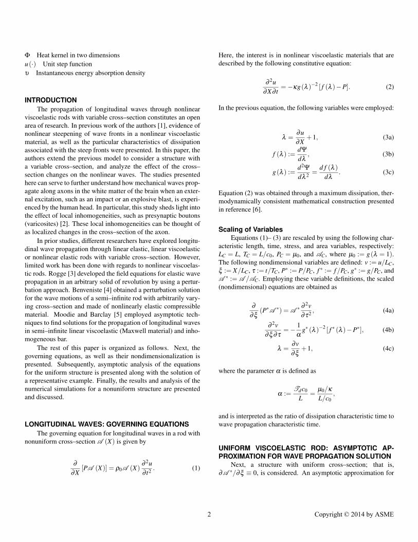
Representative ResultIn order to illustrate the effects of the material nonlinearity
and of the dissipation on the stress waves, a particular case inwhich the prescribed displacement at ξ = 0 is given by
µ (τ) =0.5(1− cos
(2π f τ
))(u(τ)−u
(τ−0.5T
))+u(τ−0.5T
) (27)
is studied. Here, T = 1/ f . In addition, the following parametersare chosen
α = 0.001,µ0
µ1=−0.03, ε = 0.001, f = 10.
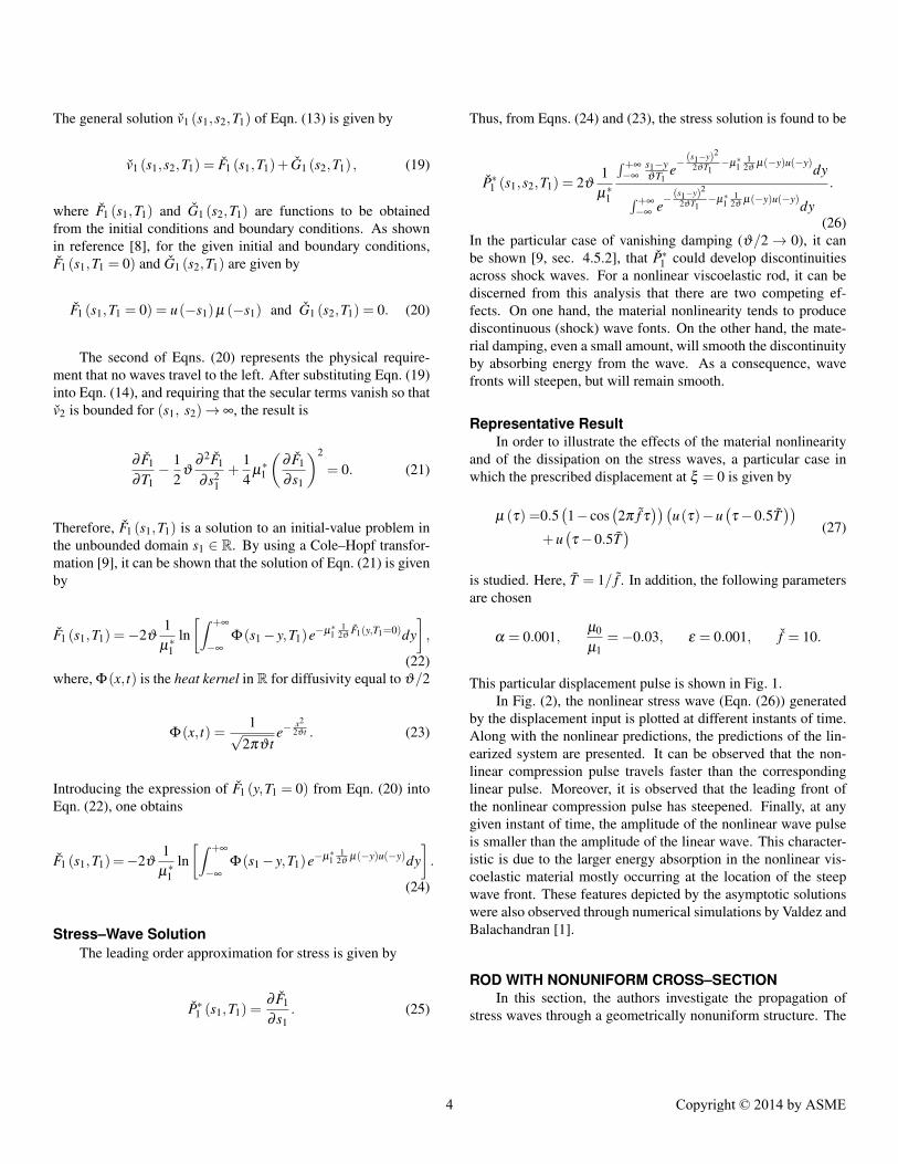
This particular displacement pulse is shown in Fig. 1.In Fig. (2), the nonlinear stress wave (Eqn. (26)) generated
by the displacement input is plotted at different instants of time.Along with the nonlinear predictions, the predictions of the lin-earized system are presented. It can be observed that the non-linear compression pulse travels faster than the correspondinglinear pulse. Moreover, it is observed that the leading front ofthe nonlinear compression pulse has steepened. Finally, at anygiven instant of time, the amplitude of the nonlinear wave pulseis smaller than the amplitude of the linear wave. This character-istic is due to the larger energy absorption in the nonlinear vis-coelastic material mostly occurring at the location of the steepwave front. These features depicted by the asymptotic solutionswere also observed through numerical simulations by Valdez andBalachandran [1].
ROD WITH NONUNIFORM CROSS–SECTIONIn this section, the authors investigate the propagation of
stress waves through a geometrically nonuniform structure. The
4 Copyright © 2014 by ASME
0 0.2 0.4 0.6 0.8 10
0.5
1
Non–dimensional time τ/T
Inpu
tStr
ess
µ(τ)
FIGURE 1. SHAPE OF THE DISPLACEMENT PULSE (Eqn. (27))INTRODUCED AT ξ = 0.
0 0.2 0.4 0.6 0.8 1−3
−2
−1
0
·10−2
τi =0.1
τi =0.45τi =0.8
Spatial location ξ
Non
–dim
ensi
onal
Stre
ssP∗ (
ξ,τ i)
FIGURE 2. SNAPSHOTS OF THE COMPRESSION STRESSWAVES PROFILES AT DIFFERENT INSTANTS OF TIME. ( ):NONLINEAR PREDICTION (Eqn. (26)); ( ): LINEAR MODELPREDICTION.
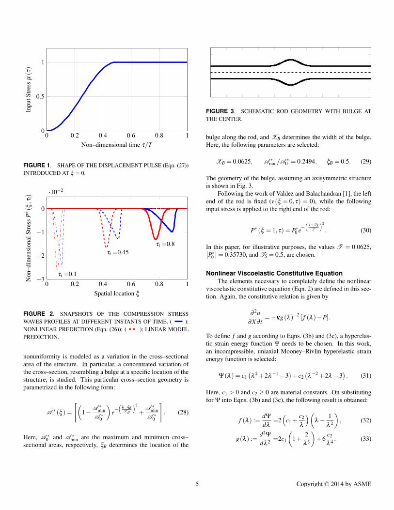
nonuniformity is modeled as a variation in the cross–sectionalarea of the structure. In particular, a concentrated variation ofthe cross–section, resembling a bulge at a specific location of thestructure, is studied. This particular cross–section geometry isparametrized in the following form:
A ∗ (ξ ) =
[(1− A ∗
minA ∗
0
)e−(
ξ−ξBXB
)2
+A ∗
minA ∗
0
]. (28)
Here, A ∗0 and A ∗
min are the maximum and minimum cross–sectional areas, respectively, ξB determines the location of the
FIGURE 3. SCHEMATIC ROD GEOMETRY WITH BULGE ATTHE CENTER.
bulge along the rod, and XB determines the width of the bulge.Here, the following parameters are selected:
XB = 0.0625, A ∗min/A
∗0 = 0.2494, ξB = 0.5. (29)
The geometry of the bulge, assuming an axisymmetric structureis shown in Fig. 3.
Following the work of Valdez and Balachandran [1], the leftend of the rod is fixed (v(ξ = 0,τ) = 0), while the followinginput stress is applied to the right end of the rod:
P∗ (ξ = 1,τ) = P∗0 e−( τ−TS
T
)2
. (30)
In this paper, for illustrative purposes, the values T = 0.0625,∣∣P∗0 ∣∣= 0.35730, and TS = 0.5, are chosen.
Nonlinear Viscoelastic Constitutive EquationThe elements necessary to completely define the nonlinear
viscoelastic constitutive equation (Eqn. 2) are defined in this sec-tion. Again, the constitutive relation is given by
∂ 2u∂X∂ t
=−κg(λ )−2 [ f (λ )−P].
To define f and g according to Eqns. (3b) and (3c), a hyperelas-tic strain energy function Ψ needs to be chosen. In this work,an incompressible, uniaxial Mooney–Rivlin hyperelastic strainenergy function is selected:
Ψ(λ ) = c1(λ 2 +2λ−1−3
)+ c2
(λ−2 +2λ −3
). (31)
Here, c1 > 0 and c2 ≥ 0 are material constants. On substitutingfor Ψ into Eqns. (3b) and (3c), the following result is obtained:
f (λ ) :=dΨ
dλ=2(
c1 +c2
λ
)(λ − 1
λ 2
), (32)
g(λ ) :=d2Ψ
dλ 2 =2c1
(1+
2λ 3
)+6
c2
λ 4 . (33)
5 Copyright © 2014 by ASME

In this case, µ0 := g(λ = 1) = 6(c1 + c2). In particular, theauthors consider c1 = c2. Thus, the nondimensional version ofEqns. (32) and (33) are given by
f ∗ (λ ) :=f (λ )µ0
=16
(1+
1λ
)(λ − 1
λ 2
), (34)
g∗ (λ ) :=g(λ )
µ0=
16
(1+
2λ 3
)+
12
1λ 4 . (35)
In addition, a value for the parameter α needs to be chosen. Forthe simulations, the value of α is set to 0.001.
Numerical Simulations ResultsIn Fig. 4, snapshots of the the stress–wave profiles are plot-
ted at different instants of time for compression and tensionpulses propagating through the nonlinear viscoelastic rod withthe bulge located at the center. In the figure, the normalizedstress P∗/
∣∣P∗0 ∣∣ is plotted against the spatial location along therod. In addition, and for the purpose of comparison, the waveprofiles developed through the corresponding uniform structureare presented at the same instants of times in Fig. 5. A closercomparison of the stress waves for the uniform and nonuniformcases shows that the wave profiles are indistinguishable from oneanother up to the point where the wave reaches the bulge, indi-cating that for this particular wave, the presence of the bulge isonly locally felt.
It is also observed that upon reaching the bulge, part of theincoming stress wave is transmitted through the bulge whereasanother portion is reflected back. In reference [8], it is arguedthat the ratio of transmitted–to–reflected wave at the bulge de-pends inversely on the size of the bulge. The more concentratedthe bulge is (XB ↘), the higher the magnitude of the reflectedwave. Finally, it is observed that for the compressive pulse, thesteep wave front developed prior to reaching the bulge is alsotransmitted through the bulge.
In earlier work of the authors [1], it was shown that whensteep wave fronts develop inside the tissue, then the tissue ab-sorbs an increased amount of energy from the wave in a concen-trated manner, at the location of the moving wave front. Thisphenomenon is thought to be potentially dangerous for soft tis-sue, like brain tissues, as they are not suited to absorb largeamounts of energy. Next, the authors study the energy absorp-tion pattern of waves propagating through the nonuniform rodwith a bulge in the center. In the case of a nonuniform struc-ture, the total (nondimensional) energy absorbed by the materialat time τ can be shown to be given by
Wd =∫ τ
0
(∫ 1
0υ (s,τ)ds
)dτ, (36)
−1
−0.5
0
0.5
τ =0.5τ =0.85τ =1.2Nor
mal
ized
Stre
ss
Compression Input
0 0.2 0.4 0.6 0.8 1−0.5
0
0.5
1 τ =0.5τ =0.85
τ =1.2
Spatial Location ξ
Nor
mal
ized
Stre
ss
Tension Input
FIGURE 4. SNAPSHOTS OF THE COMPRESSION (TOP) ANDTENSION (BOTTOM) STRESS WAVE PROPAGATING THROUGHTHE NONLINEAR VISCOELASTIC ROD WITH A BULGE LO-CATED AT ITS CENTER. ( , , ): SNAPSHOTS AT IN-STANTS τ = 0.5, 0.85, AND 1.2, RESPECTIVELY, AS INDICATEDIN THE FIGURE; ( ): SNAPSHOTS AT INTERMEDIATE IN-STANTS OF TIMES.
where
υ (ξ ,τ) = αA ∗ (ξ )[
g∗ (λ (ξ ,τ))∂λ∂τ
(ξ ,τ)]2
(37)
is the instantaneous energy absorption density.In Fig. 6, the energy absorption patterns for both the uni-
form and nonuniform cases are presented. It is observed that thepresence of the bulge, significantly affects the tissue energy ab-sorption. In particular, it is noticed that the amount of energyabsorbed by the tissue decreases significantly when the wavereaches the bulge. For this particular case of loading and bulgegeometry, it is interesting to note that despite the splitting of thewave at the bulge into transmitted and reflected portions, the en-ergy that the tissue absorbs of the reflected wave is insignificantwhen compared to the energy absorbed at the steep wave frontthat was able to pass through the bulge. In future studies, the au-thors plan to investigate the effect of the bulge size and loadingcharacteristics on the energy absorption density of nonuniformrods.
6 Copyright © 2014 by ASME

−1
−0.5
0
0.5
τ =0.5τ =0.85τ =1.2Nor
mal
ized
Stre
ss
Compression Input
0 0.2 0.4 0.6 0.8 1−0.5
0
0.5
1 τ =0.5τ =0.85τ =1.2
Spatial Location ξ
Nor
mal
ized
Stre
ss
Tension Input
FIGURE 5. SNAPSHOTS OF THE COMPRESSION (TOP) ANDTENSION (BOTTOM) STRESS WAVE PROPAGATING THROUGHTHE UNIFORM NONLINEAR VISCOELASTIC ROD. ( , ,
): SNAPSHOTS AT INSTANTS τ = 0.5, 0.85, AND 1.2, RE-SPECTIVELY, AS INDICATED IN THE FIGURE; ( ): SNAP-SHOTS AT INTERMEDIATE INSTANTS OF TIMES.
CONCLUDING REMARKSIn the present work, the effects of material nonlinear vis-
coelasticity and of geometric nonuniformity have been studied.In particular, an analytical approximation for the solution forstress–wave propagation through a uniform rod has been pre-sented and the effect of a nonuniform cross–section was exam-ined through numerical simulations. The analytical expressionfor longitudinal stress waves has been obtained with the aid ofasymptotic analysis, in particular, the method of multiple scales.The obtained analytical approximation is illustrative of the roleof the material nonlinearities on the steepening of the stress wavefronts, and the role of the material dissipation on the wave am-plitudes. The effect of a representative bulge located at the cen-ter of the structure was assessed by analyzing wave profiles andenergy dissipation characteristics. The numerical simulation re-sults show that the presence of the bulge significantly affects thestress–wave profiles near the bulge where wave reflections areproduced. As intuition dictates, and even though those resultshave not been presented in this paper, the amount of wave re-flection depends on how concentrated the bulge is. The morelocalized the cross–sectional change in the structure, the morethe wave reflection that is produced. In terms of the tissue en-ergy absorption, it was observed that the presence of the bulgecontributes to decrease the energy that the tissue takes from the
0
0.2
0.4τ =0.5τ =0.85τ =1.2
Uniform Rod
0 0.2 0.4 0.6 0.8 10
0.2
0.4τ =0.5τ =0.85τ =1.2
Spatial Location ξ
Rod with Bulge
Ene
rgy
Abs
orpt
ion
Den
sity
FIGURE 6. SNAPSHOTS OF THE INSTANTANEOUS ENERGYABSORPTION DENSITY υ (ξ ,τ) AT DIFFERENT INSTANTS OFTIME, CORRESPONDING TO A COMPRESSIVE WAVE PULSEAND FOR A UNIFORM AND A NONUNIFORM ROD. ( , ,
): SNAPSHOTS AT INSTANTS τ = 0.5, 0.85, AND 1.2, RE-SPECTIVELY, AS INDICATED IN THE FIGURE; ( ): SNAP-SHOTS AT INTERMEDIATE INSTANTS OF TIMES; ( ): EN-VELOPE.
propagating wave. Therefore, in terms of tissue damage, bulgescould represent a beneficial feature.
ACKNOWLEDGMENTPartial support received for this work through the Center for
Energetic Concepts Development at University of Maryland isgratefully acknowledged.
REFERENCES[1] Valdez, M., and Balachandran, B., 2013. “Longitudinal non-
linear wave propagation through soft tissue”. Journal ofthe Mechanical Behavior of Biomedical Materials, 20(0),pp. 192 – 208.
[2] Segev, I., and Schneidman, E., 1999. “Axons as comput-ing devices: basic insights gained from models”. Journal ofPhysiology-Paris, 93(4), pp. 263–270.
7 Copyright © 2014 by ASME

[3] Rogge, T., 1971. “Longitudinal wave propagation in barswith variable cross section”. Zeitschrift fur AngewandteMathematik und Physik (ZAMP), 22(2), pp. 299–307.
[4] Benveniste, Y., 1975. “Wave propagation in a nonlinearlyelastic compressible rod with variable cross section”. ActaMechanica, 22(3-4), pp. 197–208.
[5] Moodie, T., and Barclay, D., 1975. “Wave propagation in in-homogeneous variable-section viscoelastic bars”. Acta Me-chanica, 23(3-4), pp. 199–217.
[6] Haslach, H., 2011. Maximum Dissipation Non-EquilibriumThermodynamics and Its Geometric Structure. Springer.
[7] Nayfeh, A. H., 1973. Perturbation methods. Wiley, NewYork.
[8] Valdez, M., 2013. Analytical and Computational Investiga-tions into Wave Propagation through Soft Tissue. PhD Dis-sertation. University of Maryland, College Park.
[9] Evans, L. C., 2010. Partial differential equations, Vol. 19 ofGraduate Studies in Mathematics. American MathematicalSociety, Providence, Rhode Island.
8 Copyright © 2014 by ASME