WATER SERVICING DEVELOPMENT CHARGE UPDATE 2008 …€¦ · WATER SERVICING DEVELOPMENT CHARGE...
63
WATER SERVICING DEVELOPMENT CHARGE UPDATE 2008 FINAL REPORT Prepared for: The Corporation of the City of London Prepared by: AECOM 285 King Street, Suite 300 London, Ontario N6B 3M6 April 2009 Project No. 100875
Transcript of WATER SERVICING DEVELOPMENT CHARGE UPDATE 2008 …€¦ · WATER SERVICING DEVELOPMENT CHARGE...

WATER SERVICING DEVELOPMENT CHARGE UPDATE 2008
FINAL REPORT
Prepared for:
The Corporation of the City of London
Prepared by:
AECOM 285 King Street, Suite 300
London, Ontario N6B 3M6
April 2009 Project No. 100875

TABLE OF CONTENTS
1. INTRODUCTION ..............................................................................................................................................1
1.1. PROJECT REQUIREMENTS..............................................................................................................................1 1.2. BACKGROUND INFORMATION .......................................................................................................................3
2. EXISTING WATER SYSTEM REGULATORY REQUIREMENTS ..........................................................6
2.1. CITY OF LONDON WATER SUPPLY AND DISTRIBUTION SYSTEMS .................................................................6 2.2. RECENT REGULATORY OR OTHER WATERWORKS ........................................................................................8 2.3. STORAGE IMPLICATIONS ...............................................................................................................................9
3. DESIGN CRITERIA/FUTURE DEMAND DETERMINATION ................................................................10
3.1. SERVICE LEVEL/DESIGN CRITERIA DETERMINATION..................................................................................10 3.2. RECOMMENDED SERVICE LEVEL/DESIGN CRITERIA ...................................................................................12 3.3. FUTURE GROWTH INFORMATION ................................................................................................................12 3.4. WATER SYSTEM DEMAND DETERMINATION...............................................................................................12
4. CITY WATER SYSTEM MODELING..........................................................................................................13
4.1. MODEL DEVELOPMENT...............................................................................................................................13 4.2. DEMAND MODEL UPDATE ..........................................................................................................................14 4.3. FUTURE GROWTH MODELING .....................................................................................................................14
5. FUTURE WORK REQUIREMENTS ............................................................................................................16
5.1. PIPE RELATED WORKS................................................................................................................................16 5.1.1. Existing System Reinforcements ........................................................................................................17 5.1.2. North London ....................................................................................................................................18 5.1.3. Veterans Memorial Parkway East Area ............................................................................................19 5.1.4. Southeast London ..............................................................................................................................19 5.1.5. South London.....................................................................................................................................20 5.1.6. West London......................................................................................................................................21
5.2. FACILITY RELATED WORKS........................................................................................................................22 5.2.1. Wickerson Pumping Station Expansion.............................................................................................24 5.2.2. Uplands Pumping Station..................................................................................................................24 5.2.3. Hyde Park Pumping Station ..............................................................................................................24 5.2.4. Southeast Pumping Station and Reservoir ........................................................................................25 5.2.5. Arva Pumping Station Upgrades.......................................................................................................26
5.3. WATER SUPPLY SYSTEM WORKS................................................................................................................27 5.3.1. Elgin Area Water Supply System.......................................................................................................27 5.3.2. Lake Huron Water Supply System Works ..........................................................................................28

6. DEVELOPMENT CHARGE IMPLICATIONS............................................................................................30
6.1. POLICY IMPLICATIONS ................................................................................................................................30 6.2. GROWTH/NON-GROWTH DETERMINATION .................................................................................................31 6.3. RES/ICI ALLOCATIONS ...............................................................................................................................33 6.4. OVERSIZING................................................................................................................................................35 6.5. DEVELOPMENT CHARGE CALCULATION .....................................................................................................35
7. CONCLUSIONS AND RECOMMENDATIONS..........................................................................................37
7.1. CONCLUSIONS.............................................................................................................................................37 7.2. RECOMMENDATIONS...................................................................................................................................39

LIST OF FIGURES
Figure 1.1 Urban Growth Areas Figure 2.1 Lake Huron Water Supply System Figure 2.2 Elgin Area Water Supply System Figure 2.3 City of London Existing Water Distribution System and Facilities Figure 3.1 Population/ICI Forecast Summary Figure 5.1 Water Works to Year 2028 Figure 5.2 Water Works to Build-out Figure 5.3 Preliminary Southeast Service Zone Requirements
LIST OF TABLES
Table 3.1 Service Level/Criteria Confirmation Table 3.2A 2007 Control Tables Table 3.2B 2008 Revised Control Tables Table 3.3 Water Demand Determination Table 5.1 Recommended Low Level System Watermains Table 5.2 High Level System Watermain Components Table 5.3A City Water Distribution/Facility Components Table 5.3B Preliminary Water Supply System Components Table 5.4 EAWSS/LHWSS Expansion Requirements (July 29, 2004) Table 5.5 Future Arva Pumping Station Operation Revisions Table 6.1 Growth Needs Summary/Development Charges (to 2028)
LIST OF APPENDICES
Appendix A Regulatory Requirements Appendix A1 Revised City Water System – Certificate of Approval Appendix A2 2007 Compliance Report
Appendix B Future Growth Information Figure B1: 2007 Existing Residential Populations Figure B2: 2017 Residential Growth Figure B3: 2027 Residential Growth Figure B4: 2031 Residential Growth Figure B5: Institutional Growth Figure B6: Industrial Growth Figure B7: Commercial Growth

Water Servicing Development Charge Update 2008 Page 1
The Corporation of the City of London AECOM
Project No. 100875
1. INTRODUCTION AECOM was retained to undertake the London Water Servicing Development Charge (DC) Update 2008
for the City’s Water distribution system and facilities. Included are the City’s water supply systems from
Lake Huron and Lake Erie. The City of London last completed a Water Master Plan Update in 2003, in
support of the Development Charges implemented that year. Given the requirements to update
Development Charges on a 5-year basis, the City of London initiated this Water DC Update 2008 to
support a Development Charge 2009 By-law amendment. The intent was to reconfirm growth-related
components for the City’s water distribution and supply systems on a 5-year incremental basis over a 20-
year period (2009 to 2028), to support Development Charges for future residential, institutional,
commercial and industrial development.
1.1. Project Requirements The project required updating of the City’s Water System works completed over the last five years. This
was needed not only for water engineering planning purposes to provide servicing to new growth areas as
per current service levels, but to also support an update of the Development Charges By-law for
residential, institutional, commercial and industrial growth purposes. There were significant technical
and financial aspects related to this work, both of which were reviewed by City and development
community personnel to ensure the basis for these works, the actual works themselves and their related
costs were fairly determined and apportioned to residential, institutional, commercial and industrial
growth components. As such, consultation was needed to not only ensure a complete understanding of
the work completed, but also obtain consensus and approval amongst the Development Community and
the City of London to move forward with DC implementation on an agreed upon basis.
The City of London relies on its water infrastructure to deliver high quality service to its ratepayers
(future and existing). The tragic events of Walkerton underscored the importance of adequate investment
in water systems, however, such investments must be done in a fiscally responsible manner. Recent
legislation (the SDWA and Bill 175), is moving municipalities toward prioritized planning and full cost
recovery for their water systems. The effective management and planning of water infrastructure requires
a well-considered and planned approach that is focused on providing the appropriate level of service to
the customer, while ensuring system reliability and long term sustainability. Necessary funding from
growth, and non-growth, related sources must therefore be co-ordinated to meet this need fairly, and in a
responsible manner, to ensure no one party or group pays more than its fair share.

Water Servicing Development Charge Update 2008 Page 2
The Corporation of the City of London AECOM
Project No. 100875
To quantify and justify infrastructure expenditures, cities must carefully consider the condition and
performance of their water infrastructure based on regulatory requirements and realistic service levels.
Master Planning and hydraulic modeling remain invaluable tools in the identification of water
infrastructure needs from a performance perspective, and has gained greater relevance in the larger
context of Development Charge and more recent regulatory requirements. As such, the objectives of the
project were as follows:
• Update the City’s Water system needs to identify growth related requirements on a 5-year
incremental basis for 20 years, keeping in mind ultimate 50 year plus requirements. (City Low/High
pressure water distribution mains, pumping and storage systems, and Lake Huron Water Supply and
Elgin Area Water Supply Systems (LHWSS/EAWSS)).
• Confirm service levels based on past work, more recent regulatory and future anticipated regulatory
requirements, and historical demand patterns for residential, institutional, commercial and industrial
users in the City of London.
• Confirm costs to 2009 for required growth works, growth/non-growth components, and appropriate
residential, institutional, commercial and industrial allocations for both the City’s water distribution
system and facilities, and those components of the water supply systems from Lakes Huron and Erie
respectively.
• Take into consideration ultimate Build-out requirements to ensure appropriate distribution system
components and facilities are identified and post 2028 development can be determined.
• Co-ordinate with DC updates for Sanitary Servicing, Transportation and Stormwater
Management/Servicing being completed at the same time. This included support and assistance in
development of the City’s Growth Management Implementation Strategy (GMIS).
• Consultation with the City of London’s Environmental and Engineering Services Department,
Finance Department and Development Charges personnel at key stages of the project to reduce
potential cost and time implications, and obtain agreement with the results of the work to develop the
City’s GMIS.

Water Servicing Development Charge Update 2008 Page 3
The Corporation of the City of London AECOM
Project No. 100875
Being a DC update exercise we were to match works to needs for the 20-year growth period used for DC
application purposes, and assist in developing the City’s GMIS. Redundancies were to be removed where
applicable amongst various water, sanitary, storm and/or road related works. For work determination
purposes, major facilities, and watermains greater than or equal to 400 mm in diameter (16 in), were
included as per past Development Charges and design policy. The intent was to ensure funding for future
growth related works, and/or portions thereof, was provided for both the City’s water distribution and
supply components. The latter has historically been paid for via water rates.
1.2. Background Information The following background information was provided and reviewed/utilized for project purposes.
• National Benchmarking Partnership 2001: City of London Water Supply, City of London in Partnership with Earth Tech, Submitted 2006.
• City of London Water Master Plan Update, Earth Tech Canada Inc. (2004)
• MOEE Certificate of Approval 8869-5TDKBH, Municipal Drinking Water System, City of London, January 14, 2004 (see Appendix A1).
• City of London 2007 Annual Drinking Water Compliance Report (see Appendix A2).
• Water By-law W-1 – Consolidated, City of London, July 2, 2002.
• Hyde Park Water Pumping Station EA and Pre-Design Report, Earth Tech Canada Inc. (2001).
• Uplands Pumping Station EA and Pre-Design Report, Earth Tech Canada Inc. (2002).
• Southeast London Terminal Reservoir and Pumping Station, Final Pre-Design Report, Dillon, February, 2003.
• City of London Water Supply Reliability Assessment, Dillon, April, 2002 and related staff recommendations for emergency well decommissioning.
• Joint Master Plan Update, Dillon 2001 (updated in 2004 by separate Master Plans for each Water Supply System by Stantec Consulting).
• Summaries of billed water consumption information by customer classification to 2002.
• Summary of land use area classifications from the City’s Planning Department.
• Water System related Capital works completed over the past 4 years.
• Terms of Reference for the 2004 Development Charges By-law Steering Committee.

Water Servicing Development Charge Update 2008 Page 4
The Corporation of the City of London AECOM
Project No. 100875
• The City’s H2ONET master model (Version 3.1), initially developed by AECOM (formerly Earth Tech). (Later updated as part of the Hyde Park and Uplands Pumping Station projects and Water Master Plan Update, 2004).
• ARCINFO GIS files of existing water system information. (WIMS database 300 mm dia. or greater). Also provided was the latest OBM information.
• Latest Community Planning Study information (Riverbend, Hyde Park, Fox Hollow, Sunningdale, Uplands North and South, Stoney Creek, Killaly North and South, North Talbot, Lambeth, Bostwick, Longwoods, Old Victoria, Airport Road and Cheapside).
• City of London Water Master Plan Update, AECOM (formerly Earth Tech), 2004.
• The latest plan showing the City’s defined growth areas including the areas added in response to OMB decisions. See Figure 1.1.
• Springbank Pumping Station Pre-Design Report, Dillon 2003.
• Wickerson Road Pumping Station Class EA (Schedule B) Servicing Report, Development Engineering, 2002.
• Water Supply Study for the City of London, Environmental Study Report (ESR), Dillon, 1994.
• Southeast Reservoir and Pumping Station Design Report, AECOM (formerly Earth Tech) 2004.
Our work was to only identify all growth related works for the City in the future. The modeling
completed however identified growth, and some non-growth aspects from a hydraulic capacity
perspective.
The primary basis for the work to be completed was the 2004 Water Master Plan Update. The
information provided by this study was confirmed, updated and enhanced as needed to meet the
objectives of this project. This included addressing the objectives outlined in Section 1.1, and doing so in
an open and transparent manner so consensus could be won, and the results accepted by the Development
Community and the City for fair and effective implementation.
In addition to the background information outlined herein, other key information items were as follows:
• Master planning for the Lake Huron and Elgin Area Water Supply Systems was not included as part of this assignment. A separate Water DC update for each system was completed by Stantec Consulting, October 2004.

Water Servicing Development Charge Update 2008 Page 5
The Corporation of the City of London AECOM
Project No. 100875
• The City’s INFOWATER model was utilized for project completion purposes as per the latest model development and calibration work completed as part of the City’s Water Model development project (December 2007).
• Population and Industrial/Commercial/Institutional (ICI) growth information was provided by growth area and transportation system zones (256), in 5-year increments from 2008 to 2038 (2008, 2013 2018, 2023, 2028, 2033, 2038). These timelines determined growth area priorities. (See Appendix B).
• The service level for reservoir storage requirements continued to be based on the Reliability Assessment work completed, updated as per the emergency wells decommissioned.
• Updated unit costs to 2007 were provided by the City of London based on recent tender information. An inflation and/or index factor was applied for 2009 project cost determination purposes.
• For ultimate Build-out, the planning and population information used for the City’s previous Transportation Plan Update (2004), and for Sewerage System planning (2003), was utilized (population and ICI), to confirm future distribution system requirements beyond the urban growth boundary.
• The requirements of the Safe Drinking Water Act (Bill 195), and Bill 175 were to be addressed at this time. The latest C of A for the City’s Water Distribution System is included in Appendix A1.
All of the information outlined herein forms the basis for this project.
Water Servicing Development Charge Update 2008 Page 6
The Corporation of the City of London AECOM
Project No. 100875
2. EXISTING WATER SYSTEM REGULATORY REQUIREMENTS With the crisis in Walkerton, Ontario in 2000, the water industry has been undergoing tremendous
change. New regulations have been put in place to: protect and enforce drinking water standards
(Regulation 459 and the new Safe Drinking Water Act); ensure proper planning and financial recovery for
water/wastewater infrastructure (Bill 175 Sustainable Water and Sewage System Act and PSAB); and
promote a renewed emphasis on watershed protection (Nutrient Removal Protection Measures Act, etc.).
As a result, all of the water systems in Ontario have been intensely reviewed, with upgrades needed in
most instances to meet these new requirements. As such, the City of London’s water distribution and
supply systems, along with other systems, have been undergoing upgrades that impacts day-to-day water
provision and emergency supply requirements that carry forward for new capacity applications.
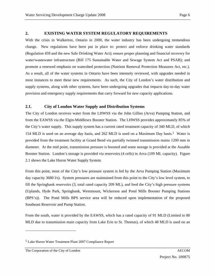
2.1. City of London Water Supply and Distribution Systems The City of London receives water from the LHWSS via the John Gillies (Arva) Pumping Station, and
from the EAWSS via the Elgin-Middlesex Booster Station. The LHWSS provides approximately 85% of
the City’s water supply. This supply system has a current rated treatment capacity of 340 MLD, of which
154 MLD is used on an average day basis, and 262 MLD is used on a Maximum Day basis.1 Water is
provided from the treatment facility at Grand Bend via partially twinned transmission mains 1200 mm in
diameter. At the mid point, transmission pressure is boosted and some storage is provided at the Ausable
Booster Station. London’s storage is provided via reservoirs (4 cells) in Arva (109 ML capacity). Figure
2.1 shows the Lake Huron Water Supply System.
From this point, most of the City’s low pressure system is fed by the Arva Pumping Station (Maximum
day capacity 3680 l/s). System pressures are maintained from this point to the City’s low level system, to
fill the Springbank reservoirs (3, total rated capacity 209 ML), and feed the City’s high pressure systems
(Uplands, Hyde Park, Springbank, Westmount, Wickerson and Pond Mills Booster Pumping Stations
(BPS’s)). The Pond Mills BPS service area will be reduced upon implementation of the proposed
Southeast Reservoir and Pump Station.
From the south, water is provided by the EAWSS, which has a rated capacity of 91 MLD (Limited to 80
MLD due to transmission main capacity from Lake Erie to St. Thomas), of which 48 MLD is used on an
1 Lake Huron Water Treatment Plant 2007 Compliance Report


Water Servicing Development Charge Update 2008 Page 7
The Corporation of the City of London AECOM
Project No. 100875
average day basis and 64 MLD is used on a Maximum Day basis. 2 For the City of London, the average
day demand from the EAWSS is approximately 23 MLD and the maximum day capacity is capped at 36
MLD. This is based on London’s current water supply agreement with the EAWSS which calls for
London to take a minimum of 22.7 MLD (5 MIGD) per day, and a maximum of 36.3 MLD (8 MIGD) per
day. This is also being done to delay future expansion of the EAWSS, with the Maximum Day capacity
from the EAWSS that would normally be used by London (currently provided by the LHWSS), being
utilized by Elgin Area users to serve growth in their service area.
The EAWSS consists of a treatment facility just east of Port Stanley at Lake Erie, and a 750 mm dia.
transmission main to St. Thomas, which constrains capacity to 80 MLD. At this point distribution
pumping and storage is provided for the St. Thomas and Aylmer Secondary Systems, and to London via
the Elgin-Middlesex Pumping Station. The reservoir facility has a storage capacity of 27 ML for London,
27 ML for the St. Thomas and Aylmer secondary users. From this point a 1050 mm dia. transmission
main continues north and enters the City of London water distribution system directly in the Highbury
Avenue/Dingman Drive area. Pressure Reducing Valves (PRV’s), are positioned in three locations
(Castleton and Jackson), to create a small pressure zone fed by the Elgin-Middlesex Pump Station.
Additional supply can be provided to the City’s east side in response to maximum day and peak hour use,
and to balance system pressures along the east side of the City via the Jackson/Commissioners Road PRV
when the EMPS is running. Figure 2.2 shows the Elgin Area Water Supply System.
In the future, the proposed Southeast Reservoir and Pumping Station will be located on the east side of
Highbury Avenue, just south of Westminster Drive as shown on Figure 2.2. Once in place, operation of
the Elgin-Middlesex Pumping Station will revert to supply and transmission only, versus providing
system pressure and meeting water demand requirements. These would then be met by the proposed
Southeast Reservoir and Pump Station with a new pressure zone being created, including the formerly
served area by the City’s low level system south of Southdale Road, and possibly the area currently
serviced by the Pond Mills Pumping Station (High pressure system), south of Commissioners Road and
east of Wellington Road.
Also part of the City’s water distribution system are four existing high pressure service zones. These are:
2 Elgin Area Water Treatment Plant 2007 Compliance Report


Water Servicing Development Charge Update 2008 Page 8
The Corporation of the City of London AECOM
Project No. 100875
• The pressure zone serviced by the Springbank, Westmount and Pond Mills Pumping Stations. This is essentially the area south of Commissioners Road, and north of Southdale Road between Byron and Highbury Avenue. The Springbank Pumping Station was expanded in 2004 to better service future growth south of Southdale Road in the Talbot Community Planning Area, and to the west along Southdale Road (north and south sides), to Boler Road.
• A new pressure zone was also created in west London served by the Wickerson Pumping Station. This services the area generally bounded by Oxford Street to the north, Westdel Bourne Road to the west, Southdale Road to the south (i.e., the Wickerson and Springbank pumping stations will in the future work in parallel), and to the east just east of Wickerson Road along the existing built up portions of the City;
• An existing small high pressure area in old Uplands, just east of Richmond Street and south of Sunningdale Road. Due to growth in the Uplands and Sunningdale areas, the service zone was expanded as part of implementation of the new Uplands Pumping Station. This high pressure zone services the Uplands and existing Richmond Hill areas, north of Fanshawe Park Road to approximately Sunningdale Road west of Richmond Street, and the areas south of Sunningdale Road, and north to the City limit, east of Richmond Street.
• The fourth pressure zone was newly created via construction of the Hyde Park Pumping Station. This involved servicing the area previously served by the Lawson Pumping Station generally bounded by Wonderland Road to the east, Gainsborough Road to the north, the existing City built up area to the west, and Sarnia Road to the south. To this was added the White Hills area previously serviced by the City’s low pressure system, and new growth areas in Hyde Park west of the built up portion of the City to approximately Hyde Park Road. In the future, this pumping station will also service higher ground areas northwest of the Fanshawe Park Road/Hyde Park intersection. See Figure 2.3 for the existing London Water Distribution System.
2.2. Recent Regulatory or Other Waterworks As per the City’s most recent Compliance Report included in Appendix A2 and current growth, the
following works have recently been completed relative to the City’s water distribution system and
facilities. Works relative to the Lake Huron and Elgin Area Water Supply Systems are outlined in the
Master Plans currently being updated for each system.
• Construction and the placement into operation of the Hyde Park Pumping Station;
• Innovation Drive from Hamilton Road to the Concept Drive.
• Commissioners Road from Jackson Road to Veterans Memorial Parkway.
• Gainsborough Road from Hyde Park Road to Coronation Drive.
• Hyde Park Road from Gainsborough Road to South Carriage Road

!(
!(
!(
!(
!(
!(
!(
!(.
WATER SERVICINGDC UPDATE 2008
FIGURE 2.3
Existing Water Distribution System and Facilities
SCALE: N.T.S
DATE: FEB 2009 PN: 100875
ARVA PS & RESERVOIR
UPLANDS PS
WESTMOUNT PSSPRINGBANK PS & RESERVOIR
WICKERSON PS
HYDE PARK PS
PROPOSED SOUTHEAST PS& RESERVOIR
Legend
Existing Watermains > 300 mm Dia.
Future Southeast Service Area
Waterways
Pump Station!(
Exising High Pressure Zone
Elgin-Middlesex (Future SE)
Urban Growth Boundary
Existing Built Out City (Sept 2006)
City Boundary
Major Roads
PONDMILLS PS

Water Servicing Development Charge Update 2008 Page 9
The Corporation of the City of London AECOM
Project No. 100875
• Construction and the placement into operation of the Uplands Pumping Station in 2004.
• High pressure watermain on Sunningdale Road. (Richmond Street to the Uplands development), and
on Richmond Street (Sunningdale south to Plane Tree), in 2004, serviced by the Uplands PS.
• High pressure watermain on Wickerson Road, 425 m south of the Wickerson Pump Station in 2004.
• High pressure watermain on Southdale between Tillman Road and Bostwick Road.
• Veteran’s Memorial Parkway from the Thames River to Commissioners.
No other existing water distribution system related works were identified by City personnel.
2.3. Storage Implications As outlined in Section 2.1, the City of London currently relies on terminal and distribution storage at the
Arva, Springbank and Elgin-Middlesex Reservoirs. The Water Supply Reliability Assessment Final
Report dated April 2002 reviewed various emergency scenarios to identify how the City’s supply and
water distribution systems, and storage facilities, could address different emergency situations with
varying degrees of risk of occurrence. Those of most concern were:
1. Lake Huron water supply system off line for one maximum day and one average day; 2. Same as above with a water demand 1.3 times average day, plus two average days.
Based on these scenarios, the City’s current one day storage deficit is 60 ML. This current deficit will
have to be overcome by the provision of additional storage capacity, which is intended to be provided by
the proposed Southeast Reservoir and Pump Station. Scenario 1 translates to a 115 ML storage deficit
over 2 days. Scenario 2 translates to a 130 ML storage deficit over 3 days. The City’s current total
reservoir capacity is 318 ML.3 Additional storage is also required to accommodate new growth in the
future.
3 City of London 2007 Annual Drinking Water Compliance Report

Water Servicing Development Charge Update 2008 Page 10
The Corporation of the City of London AECOM
Project No. 100875
3. DESIGN CRITERIA/FUTURE DEMAND DETERMINATION Before future growth related works could be identified, the design criteria were confirmed and future
population and Institutional/Commercial/Industrial (ICI), growth information provided. Both pieces of
information were confirmed and then utilized to determine water system demands for the City of London
over a 20 year growth and ultimate (675,000 population), basis. The criteria confirmed and recommended
for use and the growth information provided by the City of London utilized to determine water system
demands on which to base future work requirements are outlined herein.
3.1. Service Level/Design Criteria Determination Table 3.1 outlines the service level/design criteria reviewed as part of the Water Master Plan Update 2003
leading to recommendations for those used for project purposes. Previously shown is the following:
• Design standards used by the City of London based on the “City of London General Requirements,
Specifications and Standard Drawings for Water Distribution Systems 2003, Updated 2005”, and the
MOE Design Manual. We would point out the MOE Design Guidelines are not enforcement
standards.
• Planning criteria used as part of past projects. Included is the criteria used for the Waterworks Master
Plan Update in 2003.
Various design and/or planning criteria is shown as follows:
• Minimum peak hour, maximum day plus fire flow and maximum/minimum system pressure criteria.
• Maximum velocities and headlosses for watermains greater than or equal to 400 mm in diameter.
(Cut-off for major feeder or transmission mains. Also cut-off for Development Charge recovery
purposes).
• Existing water system operational information was used as a basis for previous study efforts and for
this project. For the purposes of this project, the base Winter Average Day Demand (ADDw), to be
used as a starting point for the assessment was determined to be 148.2 ML/d. This was based on the
City of London 2007 Annual Drinking Water Compliance Report.

Water Servicing Development Charge Update 2008 Page 11
The Corporation of the City of London AECOM
Project No. 100875
Maximum Day Demand (MDD), and Peak Hour Demand (PHD), was then determined, using the
City’s agreed upon peaking factors for planning application purposes (i.e., globally across the City),
shown by Table 3.1. In this instance design criteria varies significantly from planning criteria. The
City design criteria is applied on a development by development basis. Therefore higher max day and
peak hour peaking factors are used for design purposes.
• For new growth unit demand application purposes, average day use was defined as winter day.
AECOM reviewed water consumption and pumpage information as part of the previous Water Master
Plan Update 2003 which resulted in a design standard of 270 Lpcd being used for project purposes.
The same criteria was used for Institutional, Commercial and Industrial (ICI) usage on a litres per
hectare per day (L/ha/d) basis, established as part of the Water Master Plan Update 2003. Again
global peaking factors were used as per the information provided in Table 3.1. In the future, the City
hopes to be able to apply peaking factors on a diurnal basis for each land use class. This cannot be
completed until:
a) The City’s water model is expanded to include all of the City’s water distribution system which
has been done;
b) The City’s billing record classifications are consistent with the City’s planning land use
classifications (still to be done); and
c) Sufficient data is obtained, based on the above, to map diurnal curves and then determine
specific land use peaking factors (this has been done to some extent). In the past this had been
done on a hypothetical basis.
A global approach is consistent with the approach used as part of previous study and development
charge determination work.
• Fire flows for residential and ICI land uses were identified as per City and MOE criteria. City criteria
were used in each instance.
• Storage Capacity from a distribution and terminal perspective was identified in 1994 and further in
1999/2000. This deficit has increased based on outputs of the City’s Water Reliability Assessment

P:\P
RO
JEC
TS\1
0087
5 Ld
n W
ater
DC
Upd
ate\
Gen
Cor
\Rep
orts
\Fin
al R
epor
t\Tab
les\
Tabl
e 3.
1 Se
rvic
e Le
vel_
Crit
eria
Con
firm
atio
n.do
c
TA
BL
E 3
.1
CIT
Y O
F L
ON
DO
N
WA
TE
R S
ER
VIC
ING
DC
UPD
AT
E 2
008
SER
VIC
E L
EV
EL
/CR
ITE
RIA
CO
NFI
RM
AT
ION
(R
evis
ed J
anua
ry 2
3, 2
009)
Item
D
esig
n St
anda
rds
Plan
ning
Cri
teri
a R
ecom
men
ded
C
ity1
MO
E2
1994
3 19
994
2000
5 20
0815
Min
imum
pea
k ho
ur
pres
sure
(kPa
) 27
5 (3
10 fo
r ind
ustri
al)
275
275
(310
for i
ndus
trial
) 27
5 (3
10 fo
r ind
ustri
al)
275
(310
for i
ndus
trial
) 27
5 (3
10 fo
r in
dust
rial
)
Min
imum
max
imum
day
pl
us fi
re fl
ow p
ress
ure
(kPa
)
140
140
140
140
140
140
M
axim
um/M
inim
um
syst
em p
ress
ure
(kPa
) 69
0/27
5 70
0/27
5 (D
esig
n to
550
/350
fo
r nor
mal
ope
ratin
g co
nditi
ons u
nder
max
. flo
w)
700/
275
690/
275
690/
275
690/
275
M
axim
um v
eloc
ity (m
/s)
3.0
Not
Iden
tifie
d 3.
0 3.
0 3.
0 3.
0 (m
ains
> 4
00 m
m in
dia
)
M
axim
um h
eadl
oss (
m/k
m)
2.3
Not
Iden
tifie
d 2.
3 2.
3 2.
3 2.
3 (m
ains
> 4
00 m
m in
dia
)
Ex
istin
g sy
stem
ope
ratio
n •
Win
ter A
DD
(ML/
D)6
• M
DD
(ML/
D)6
-Glo
bal p
eaki
ng fa
ctor
•
PHD
(ML/
D)6
- Glo
bal p
eaki
ng fa
ctor
15
5-19
8 (4
70-6
00
Lcpd
)7
3.
58
7.88
N
ot A
pplic
able
150
300 2
450 3
15
5 28
7 1.
85
43
6 2.
81
14
8 28
9 1.
95
46
2 3.
12
14
816
28
9 1.
9510
46
2 3.
1210

P:\P
RO
JEC
TS\1
0087
5 Ld
n W
ater
DC
Upd
ate\
Gen
Cor
\Rep
orts
\Fin
al R
epor
t\Tab
les\
Tabl
e 3.
1 Se
rvic
e Le
vel_
Crit
eria
Con
firm
atio
n.do
c
TA
BL
E 3
.1
CIT
Y O
F L
ON
DO
N
WA
TE
R S
ER
VIC
ING
DC
UPD
AT
E 2
008
SER
VIC
E L
EV
EL
/CR
ITE
RIA
CO
NFI
RM
AT
ION
(R
evis
ed J
anua
ry 2
3, 2
009)
Item
D
esig
n St
anda
rds
Plan
ning
Cri
teri
a R
ecom
men
ded
C
ity1
MO
E2
1994
3 19
994
2000
5 20
0815
New
gro
wth
are
as A
DD
6
•
Res
iden
tial (
Lpcd
)
- Max
. day
fact
or
- P
eak
hour
fact
or
•
Com
mer
cial
(L/h
a/D
)
- Max
. day
fact
or
- P
eak
hour
fact
or
•
Inst
itutio
nal (
L/ha
/D)
- M
ax. d
ay fa
ctor
- Pea
k ho
ur fa
ctor
• In
dust
rial (
L/ha
/D)
- M
ax. d
ay fa
ctor
- Pea
k ho
ur fa
ctor
27
09,14
3.
5 7.
8 25
,000
– 5
0,00
0
Not
pro
vide
d
Not
pro
vide
d
27
0 –
450
1.5
– 2.
7511
2.25
– 4
.1311
28,0
00
Not
Pro
vide
d
1.5
- 4
90
0 –
1,80
0 (L
/bed
/day
)
70 –
140
(L
/stu
dent
/day
) 35
,000
– 5
5,00
0 N
ot P
rovi
ded
2 –
4
23
0 2
24
0 2 3 15
,000
1.
33
2.11
15,0
00
1.33
1.
69
35
,000
1.
33
1.65
24
0 1.
95
3.12
10,4
50
1.95
3.
12
14
,850
1.
95
3.12
17,2
70
1.95
3.
12
27
09,14
1.
9510
3.12
10
7,
2009
1.95
10
3.12
10
14
,700
9 1.
9510
3.
1210
16,2
009
1.95
10
3.12
10
Fi
re fl
ows
• R
esid
entia
l (L/
s)
• IC
I (L/
s)
76
151
30
12
3012
76
151
76
151
76
151
76
151
St
orag
e ca
paci
ty
• D
istri
butio
n (M
L)
(D
efic
it)
• Te
rmin
al (M
L)
(D
efic
it)
N
/A
(B
ased
on
App
endi
x N
, M
OE
Des
ign
Gui
delin
es)
10
3 (6
1)
(4
6)
(4
6)
(4
3-60
)13

P:\P
RO
JEC
TS\1
0087
5 Ld
n W
ater
DC
Upd
ate\
Gen
Cor
\Rep
orts
\Fin
al R
epor
t\Tab
les\
Tabl
e 3.
1 Se
rvic
e Le
vel_
Crit
eria
Con
firm
atio
n.do
c
Not
es: 1
City
of L
ondo
n G
ener
al R
equi
rem
ents
, Spe
cific
atio
ns a
nd S
tand
ard
Dra
win
gs fo
r the
Wat
er D
istri
butio
n Sy
stem
, 200
3, U
pdat
ed 2
005.
2
MO
E M
anua
l. T
he in
form
atio
n id
entif
ied
is p
rese
nted
as d
esig
n gu
idel
ines
, not
enf
orce
men
t sta
ndar
ds.
3 W
ater
wor
ks M
aste
r Pla
n U
pdat
e to
201
6, D
illon
Con
sulti
ng, 1
994.
4
Wat
erw
orks
for C
ity G
row
th A
rea
Rep
ort,
Proc
tor &
Red
fern
(now
Ear
th T
ech)
, 199
9.
5 R
evie
w o
f Wat
er D
eman
d Fo
reca
stin
g, E
arth
Tec
h C
anad
a In
c., 2
000.
6
Mod
el S
cena
rios A
DD
= W
inte
r Ave
rage
Dai
ly D
eman
d; M
DD
= M
axim
um D
ay D
eman
d; P
HD
= P
eak
Hou
r Dem
and.
7
330,
000
peop
le u
sed
for c
onve
rsio
n pu
rpos
es.
8 Pe
akin
g fa
ctor
s app
licab
le to
smal
ler d
evel
opm
ent a
reas
ver
sus t
he C
ity a
s a w
hole
, or l
arge
are
as.
9 C
onfir
med
afte
r th
e re
view
of
2000
and
200
1 bi
lling
dat
a, a
nd 2
000,
200
1 an
d 20
02 p
umpa
ge in
form
atio
n.
Am
ende
d by
200
2 w
ater
pum
page
info
rmat
ion
from
A
mer
ican
Wat
er.
Subj
ect t
o co
nfirm
atio
n.
10
As p
er th
e m
emo
pres
ente
d to
the
Dev
elop
men
t Cha
rges
Join
t Tec
hnic
al S
teer
ing
Com
mitt
ee, F
ebru
ary
24, 2
003.
11
A
ctua
l fac
tor i
s det
erm
ined
by
popu
latio
n of
new
serv
ice
area
, (A
ppen
dix
L, M
OE
Des
ign
Gui
delin
es 1
984)
. 12
M
inim
um fl
ow fo
r the
ent
ire sy
stem
whi
le si
mul
tane
ousl
y sa
tisfy
ing
the
max
imum
day
dem
and.
13
W
ater
Sup
ply
Rel
iabi
lity
Ass
essm
ent R
epor
t, D
illon
Con
sulti
ng, 2
002.
Sub
ject
to u
pdat
e ba
sed
on w
ell r
emov
als i
n re
spon
se to
SD
WA
requ
irem
ents
. 14
C
onfir
med
as,
per c
apita
flow
s in
new
er a
reas
dev
elop
ed a
fter 1
996.
May
16,
200
3 C
ity m
emo.
15
A
s per
Wat
er M
aste
r Pla
n U
pdat
e, A
ECO
M (f
orm
erly
Ear
th T
ech)
, 200
4.
16
City
of L
ondo
n, 2
007
Ann
ual D
rinki
ng W
ater
Com
plia
nce
Rep
ort

Water Servicing Development Charge Update 2008 Page 12
The Corporation of the City of London AECOM
Project No. 100875
Report, Dillon, 2002. Details were provided in Section 2.3. This information was utilized as the
basis for storage capacity deficit and available capacity determination purposes.
3.2. Recommended Service Level/Design Criteria Table 3.1 also presents the criteria recommended for use on a planning basis for the development of water
demand projections for future residential, commercial, institutional and industrial land uses as part of the
Water Master Plan Update 2003. These are shown to the far right of the table in bold and are
recommended for project use again as per the rational outlined above.
3.3. Future Growth Information Future water system demands were determined using the above service level/design criteria information,
and the population and land use projection information provided by the City of London in hard copy and
digital form as discussed herein.
The City of London developed future population growth information for the period from 2009 to 2028 in
5-year increments (2013, 2018, 2023). See Table 3.2. Additional years were added to 2032 to address
potential oversizing needs, and further information was provided to 2037 to compare directly to
Institutional, Commercial and Industrial (ICI) employment growth information provided by Clayton
Research for ICI purposes (2007). Clayton’s work also verified the City’s population growth
information, with related amendments for net and gross populations included in the digital information
provided by the City to AECOM in January 2008. This information, plus later updates and/or
amendments, formed the basis for the planning work completed for all services. This included reducing
industrial areas to an amount consistent with the City’s Industrial Development Strategy and the Clayton
Forecast to 2007 as was done previously, and confirming those portions of the City to be serviced over
the 20 year planning period as per GMIS development. This information was used to define the works
required for each population projection and area, and related oversizing (if applicable), for each service
assessed. See Figure 3.1 for existing population, 20-year growth, Urban Growth Boundary and Build-out
information.
3.4. Water System Demand Determination Table 3.3 shows the water demand forecasts developed from the population and ICI information provided
by the City, using the design criteria summarized at the bottom of the table. The table shows calculated

2007
Con
trol
Tot
als
avg
ppu
in 2
007
2.23
Res
iden
tial G
row
th F
orec
asts
avg
ppu
in 2
037
2.13
Tota
ls B
ased
on
Traf
fic Z
one
Bre
ak-o
uts
Pop
ulat
ion
Pop
. Gro
wth
Res
. Uni
tsU
nit G
row
th20
0735
5,67
5
15
9,78
7
2012
371,
805
16,1
30
17
0,61
0
10,8
23
20
1738
8,60
1
16
,796
181,
433
10
,823
2022
405,
300
16,6
99
19
1,28
9
9,85
6
2027
421,
200
15,9
00
19
9,81
6
8,52
7
sub
tota
l - 2
027
65,5
25
40
,029
2032
434,
995
13,7
95
20
7,03
8
7,22
2
2037
455,
444
20,4
49
21
3,45
1
6,41
3
tota
l to
2037
99,7
69
53
,664
Con
trol
Tot
als
Indu
stria
l/Com
mer
cial
/Inst
itutio
nal F
orec
ast s
Gro
wth
of S
pace
- 20
07-2
037
(2)
Em
ploy
men
t Gro
wth
- 20
07-2
037
(1)
Indu
stria
l s
q.m
Com
mer
cial
sq.
mIn
stitu
tiona
l sq.
m.
Indu
stria
l Em
p.C
omm
erci
al E
mp.
Inst
itutio
nal E
mp.
At H
ome/
Oth
erTo
tal E
mpl
2007
2012
190,
451
125,
415
11
1,48
4
2,56
3
2,90
3
1,08
1
510
7,
057
2017
190,
451
125,
415
11
1,48
4
2,56
3
2,90
3
1,08
1
510
7,
057
2022
190,
451
125,
415
11
1,48
4
2,26
5
2,30
6
1,71
4
220
6,
505
2027
120,
774
106,
835
65
,032
1,43
6
1,96
4
1,00
0
220
4,
621
2032
120,
774
106,
835
65
,032
1,43
6
1,96
4
1,00
0
220
4,
621
2037
120,
774
106,
835
65
,032
1,43
6
1,96
4
1,00
0
220
4,
621
933,
675
696,
750
529,
548
11,7
0014
,005
6,87
71,
900
34,4
81
Floo
r Are
a R
atio
(3)
23.0
%25
.0%
42.0
%
Gro
wth
of S
pace
- 20
07-2
037
(4)
Not
es:
Indu
stria
l (h
a)C
omm
erci
al (h
a)In
stitu
tiona
l (ha
)(1
) Em
ploy
men
t gro
wth
fore
cast
by
Cla
yton
Res
earc
h A
ssoc
iate
s Lt
d20
07(2
) Flo
or s
pace
con
vers
ions
by
Cla
yton
Res
earc
h A
ssoc
iate
s Lt
d.20
1283
50
27
(3
) Flo
or a
rea
ratio
bas
ed o
n C
ity o
f Lon
don
GIS
cal
cula
tion
of e
xist
ing
spac
e (2
006-
2007
)20
1783
50
27
(4
) C
onve
rsio
n ba
sed
on fl
oor a
rea
ratio
ass
umpt
ion s
2022
83
50
27
2027
53
43
15
300.
9219
3.23
95.1
2
2032
53
43
15
2037
53
43
15
405.
9527
8.70
126.
08
(Rev
ised
Jan
uary
23,
200
9)
TA
BL
E 3
.2A
CIT
Y O
F L
ON
DO
NW
AT
ER
SE
RV
ICIN
G D
C U
PDA
TE
200
820
07 C
ON
TR
OL
TA
BL
ES

2007
Con
trol
Tot
als
avg
ppu
in 2
008
2.35
Res
iden
tial G
row
th F
orec
asts
avg
ppu
in 2
033
2.23
Tota
ls B
ased
on
Traf
fic Z
one
Bre
ak-o
uts
Pop
ulat
ion
Pop
. Gro
wth
Res
. Uni
tsU
nit G
row
th20
08*
358,
863
152,
533
20
13*
375,
160
16,2
97
16
2,92
6
10,3
93
20
18*
391,
940
16,7
80
17
2,76
6
9,84
0
2023
*40
8,48
0
16
,540
181,
745
8,
979
20
28*
423,
960
15,4
80
18
9,47
3
7,72
9
2033
*43
7,09
0
13
,130
196,
141
6,
668
Con
trol
Tot
als
Indu
stria
l/Com
mer
cial
/Inst
itutio
nal F
orec
ast s
Gro
wth
of S
pace
- 20
08-2
028
(2)
Em
ploy
men
t Gro
wth
- 20
08-2
028
(1)
Indu
stria
l s
q.m
Com
mer
cial
sq.
mIn
stitu
tiona
l sq.
m.
Indu
stria
l Em
p.C
omm
erci
al E
mp.
Inst
itutio
nal E
mp.
At H
ome/
Oth
erTo
tal E
mpl
2008
-201
3*19
0,45
1
12
5,41
5
111,
484
2,
562
2,
903
1,
081
51
0
7,05
7
20
13-2
018*
190,
451
125,
415
11
1,48
4
2,49
7
2,76
1
1,16
7
452
6,
877
2018
-202
3*17
6,51
6
12
1,69
9
102,
194
2,
099
2,
239
1,
571
22
0
6,13
0
20
23-2
028*
120,
774
106,
835
65
,032
1,43
6
1,96
6
1,00
0
220
4,
622
678,
192
479,
364
390,
194
8,59
59,
869
4,82
01,
402
24,6
86
Floo
r Are
a R
atio
(3)
23.0
%30
.0%
42.0
%
Gro
wth
of S
pace
- 20
07-2
037
(4)
Not
es:
Indu
stria
l (h
a)C
omm
erci
al (h
a)In
stitu
tiona
l (ha
)* i
nter
pola
tion
of C
layt
on 2
007
Upd
ate
to 2
006
Empl
oym
ent,
Popu
latio
n, H
ousi
ng a
nd
2008
* N
on-r
esid
entia
l Con
stru
ctio
n Pr
ojec
tions
(200
6) U
pdat
e St
udy
to m
atch
tim
e ho
rizon
of
2013
*83
42
27
2
009
DC
Bac
kgro
und
Stud
y520
18*
83
42
27
(1)
Empl
oym
ent g
row
th fo
reca
st b
y C
layt
on R
esea
rch
Ass
ocia
tes
Ltd
2023
*77
41
24
(2
) Flo
or s
pace
con
vers
ions
by
Cla
yton
Res
earc
h A
ssoc
iate
s Lt
d.20
28*
53
36
15
(3) F
loor
are
a ra
tio c
alcu
latio
ns b
ased
on
City
of L
ondo
n La
nd N
eeds
Bac
kgro
und
Stud
y
dat
ed M
ay, 2
007
295
160
93(4
) C
onve
rsio
n ba
sed
on fl
oor a
rea
ratio
ass
umpt
ions
(5)
'Pop
ulat
ion
grow
th' ,
'Uni
t Gro
wth
' and
'uni
t den
sity
ass
umpt
ions
' orig
inal
ly p
rovi
ded
by
Cla
yton
Stu
dy (2
006)
. Th
e st
udy
was
upd
ated
by
Cla
yton
in 2
007
and
the
upda
ted
figur
es
wer
e us
ed to
inte
rpol
ate
the
grow
th fo
reca
sts
refle
cted
abo
ve.
2008
RE
VIS
ED
CO
NT
RO
L T
AB
LE
S(R
evis
ed J
anua
ry 2
3, 2
009)
TA
BL
E 3
.2B
CIT
Y O
F L
ON
DO
NW
AT
ER
SE
RV
ICIN
G D
C U
PDA
TE
200
8

ADD MDD PHD ADD MDD PHD ADD MDD PHD ADD MDD PHD ADD MDD PHD ADD MDD PHD2007 355,6752012 371,805 16,130 4.4 8.5 13.6 82.8 1.3 2.6 4.2 50.2 0.4 0.7 1.1 26.5 0.4 0.8 1.2 1.1 2.2 3.5 7.6 14.8 23.62017 388,601 16,796 4.5 8.8 14.1 82.8 1.3 2.6 4.2 50.2 0.4 0.7 1.1 26.5 0.4 0.8 1.2 1.1 2.2 3.5 7.8 15.1 24.22022 405,300 16,699 4.5 8.8 14.1 82.8 1.3 2.6 4.2 50.2 0.4 0.7 1.1 26.5 0.4 0.8 1.2 1.1 2.2 3.5 7.7 15.1 24.12027 421,200 15,900 4.3 8.4 13.4 52.5 0.9 1.7 2.7 42.7 0.3 0.6 1.0 15.5 0.2 0.4 0.7 1.1 2.2 3.5 6.8 13.3 21.22032 434,995 13,795 3.7 7.3 11.6 52.5 0.9 1.7 2.7 42.7 0.3 0.6 1.0 15.5 0.2 0.4 0.7 1.1 2.2 3.5 6.2 12.2 19.52037 455,444 20,449 5.5 10.8 17.2 52.5 0.9 1.7 2.7 42.7 0.3 0.6 1.0 15.5 0.2 0.4 0.7 1.1 2.2 3.5 8.0 15.7 25.1
Total 2007 - 2027 421,200 65,525 17.7 34.5 55.2 300.9 4.9 9.5 15.2 193.2 1.4 2.7 4.3 95.1 1.4 2.7 4.4 4.5 8.8 14.0 36.1 70.4 112.6Total 2007 - 2037 455,444 99,769 26.9 52.5 84.0 405.9 6.6 12.8 20.5 278.7 2.5 4.9 7.8 126.1 3.1 6.1 9.7 4.5 8.8 14.0 59.6 116.1 185.8
(1) Source - City of London/Clayton, 2007(2) Source - City of London/Clayton, 2007(3) Industrial add-In based on total 1.0 MIGD ADDw (20 years) and 1.5 MIGD ADDw (30 years) as per Sanitary Sewer DC Update, 2008
Global Peaking Factors - Applied to ADDMDD 1.95PHD 3.12
Unit Demand Factors - Based on ADDwResidential 270 l/c/dIndustrial 16,200 l/Ha/dCommercial 7,200 l/Ha/dInstitutional 14,700 l/Ha/d
P:\PROJECTS\100875 Ldn Water DC Update\GenCor\Reports\Final Report\Tables\[Table 3.3-Jan23'09.xls]Water Demand
Total Population
Growth (Pop'n)
Growth Demands (ML/d) Growth (Ha)
Growth Demands (ML/d) Growth (Ha)
Growth Demands (ML/d)
Growth (Ha)
(Revised Jan 23, 2009)
Year Residential (1) Industrial (2) Commercial (2) Institutional (2) Industrial Add-In (3) Total Growth Demands (ML/d)Growth Demands
(ML/d)Growth Demands
(ML/d)
TABLE 3.3CITY OF LONDON
WATER SERVICING DC UPDATE 2008WATER DEMAND DETERMINATION

CITY OF LONDON BOUNDARY
HIG
HBU
RY
AVE S
River
Dingman
HAMILTON RD
DUNDAS ST
HY
DE
PAR
K R
D
Thames
CP RAIL
Creek
Pottersburg
CO
LON
EL TALB
OT R
D
River
Thames
WO
ND
ER
L AN
D R
D N
Medway
WINDERMERE RD
Creek
FANSHAWE PARK RD W
WES
TER
N R
D
SOUTHDALE RD W
WO
ND
ER
LAN
D R
D S
WH
AR
NC
LIFFE R
D N
River
Thames
HIG
HB
UR
Y AV
E N
OXFORD ST E
AD
ELA
IDE
ST N
Thames
HURON ST
TRAFALGAR ST
CR
UM
LIN S
IDE
RD
AIR
PO
RT R
D
CP RAIL
River
SUNNINGDALE RD W
RIC
HM
ON
D S
TRE
ET
FANSHAWE PARK RD E
River
Thames
CLA
RK
E R
D
LONDON
CN RAIL
AIRPORT
SPRINGBANK DR
OXFORD ST W
Stoney
SUNNINGDALE RD E
CN RAIL
Creek
WELLIN
GTO
N R
D
Creek
CN
RAIL
SOUTHDALE RD E
BRADLEY AVE
COMMISSIONERS RD W
AD
ELA
IDE
ST S
COMMISSIONERS RD E
DINGMAN DR
WESTMINSTER DR
SCOTLAND DR
WH
ITE O
AK R
D
OLD
VIC
TOR
IA RD
WO
ND
ER
LAN
D R
D S
GLANWORTH DR
WELLIN
GTO
N R
D S
HIG
HBU
RY AV
E S
DUNDAS ST
WHARNCLIFFE RD S
MANNING DR
HWY 401HWY 402
AIRPORT RD
.
ULTIMATE BUILDOUTPeople: 319,375 (Gross)
IND: 5401 haCOM: 604 haINS: 390 ha
Includes Infill andIntensification
URBAN GROWTHBOUNDARY
People: 166,950(Gross)
IND: 2662 haCOM: 520 haINS: 390 ha
Includes Infill andIntensification
EXISTING POPULATIONPeople: 355,675
IND: 2163 haCOM: 1505 ha
INS: 995 ha
2028 POPULTATIONWITHIN THE GMIS BOUNDARY
People: 421,200 (Gross)Net: 65,525
IND: 301 haCOM: 193 ha
INS: 95 ha
WATER SERVICINGDC UPDATE 2008
FIGURE 3.1
POPULATION/ICI FORECASTSUMMARY
SCALE: N.T.S
DATE: FEB 2009
Legend
Ultimate Build Out Boundary (675,000 Population) (Net Area 9030 ha)
Urban Growth Boundary (Net Area 4737 ha)
Existing Built Out City Sept 2006 (Area 18931 ha)
PN: 100875
0 2 4 6 81Kilometres
City Boundary
Major Roads RoadwaysWaterwaysGMIS Boundary

Water Servicing Development Charge Update 2008 Page 13
The Corporation of the City of London AECOM
Project No. 100875
water demands for Average Day Demand (ADDw), for each land use type by year (2008, 2013, 2018,
2023, 2028, 2032, 2037), along with total growth and water system demands for average day, maximum
day and peak hour use. In addition, an industrial demand add-in equivalent to 4.5 MLD (1.0 MIGD), over
the 20-year growth period, primarily in the core area of the City, was added as provided by the City of
London through the Sanitary DC Update. This was done as part of the previous DC Update work. No
other allowances were put in place, although pipe sizing for industrial growth areas in the City, primarily
in the southeast portion of the City, were assessed based on the use of design industrial flows, versus the
planning flow figures shown in Table 3.3. Although some increased pipe sizing was warranted, pipe
sizing was left as per the planning needs and the criteria outlined. Pipe reinforcement via some of the
“Build-out” works identified would be required for growth flows in excess of planning needs.
4. CITY WATER SYSTEM MODELING The City’s InfoWater model was used as the basis for our work. The existing water system model was
expanded to a full water system model complete with field calibration and validation as part of the City’s
model project. This was further expanded upon with future water demands being added for various
growth scenarios provided and included (UGB/Build-out scenario) as part of the Water Master Plan
Update 2003. Watermains greater than 400 mm (16”) in diameter were added to the model to service
future growth areas for Development Charge determination purposes. Water system needs below this
service level will be determined on a case-by-case basis as development areas proceed to construction.
4.1. Model Development The City’s water system master model (InfoWater) was used as the basis for the work to be completed for
this project. It includes:
• all City watermains (high and low pressure); • the primary pumping stations at Arva and St. Thomas (Elgin-Middlesex); • the Arva, Springbank and Elgin-Middlesex reservoirs; • the high pressure water pumping stations in Westmount, Springbank, Pond Mills, Uplands,
Wickerson and Hyde Park and the future Southeast PS (reservoir also); and • all key control valves and/or points.
Model calibration was updated as part of the London Water Model project using the latest SCADA
data, and flow/pressure/storage level information provided by the City (2008 data), for a Max day
event.

Water Servicing Development Charge Update 2008 Page 14
The Corporation of the City of London AECOM
Project No. 100875
• The Master model was further expanded to include works completed over the past 2 years since the
2006 full system model set-up was completed by AECOM.
4.2. Demand Model Update Existing water system demands were updated in the model as developed through the London Water
Model project. We then added future demand information based on the 20 year growth projections
provided by the City, allocated as per the previous Water Master Plan Update 2003.
Modeled water demands for each node were then determined based on unit demand factors for
Residential, Industrial, Institutional and Commercial uses as per the criteria outlined in Table 3.1. Water
demands were calculated on an average winter day basis for each model year. Maximum day and peak
hour demands were calculated based on the peaking factors outlined in Table 3.1.
4.3. Future Growth Modeling The City’s InfoWater Model updated to January, 2008 was used for works determination purposes. Some
key watermains 300 mm (12”) in diameter and all trunk watermains greater than or equal to 400 mm in
diameter were included in the model, along with Pumping Stations and reservoirs to service growth areas
of the City, and the water demands to be met over the next 20 years and beyond as per Table 3.3. Both
low and high level water system conditions were modeled separately and collectively using InfoWater.
Given the smaller area serviced by the City’s High Level water systems, peaking factors of 2.5 max day
and 5.0 peak hour were used as per the Water Master Plan 2003. The following conditions were modeled
for works determination purposes:
• Average Day • Average Day Extended Period Simulation (EPS) • Maximum Day (EPS) • Maximum Day plus Fire Flow • Peak Hour
Peak hour demands are generally the critical flow used for trunk watermain design. However, once pipe
sizes were determined, the water system was checked using a 24 hour EPS run for Average and
Maximum Day Demand to examine distribution characteristics for facility and operational optimization
purposes. Input and output information will be provided to the City of London in digital form, along with
the latest InfoWater model inputs and outputs, under separate cover. Modeling was completed for the
following growth scenarios:

Water Servicing Development Charge Update 2008 Page 15
The Corporation of the City of London AECOM
Project No. 100875
• 2008, 2012, 2022 and 2028; • Full Build-out of the City’s Urban Growth Boundary (and Modified via the removal of industrial land
area). • Ultimate Build-out for a future population of 675,000 people.
The hydraulic analysis included the following evaluation of each scenario operation:
• Each model run was assessed to ensure maximum and minimum pressure criteria was maintained throughout the City’s water system;
• Existing and proposed mains were assessed to ensure maximum headloss gradient and velocities were within design criteria;
• Storage balancing and filling was assessed to ensure adequate operation; • Pump operation was assessed to ensure pumps operated within a reasonable range of flow and Total
Dynamic Head (TDH). Based on the model results, new mains were added to either upsize (or twin) existing watermains, to
provide looping, to add or upgrade facilities, or to service new growth areas. System analysis was
completed for each of the above scenarios as follows.
• An analysis was initially completed for the year 2037 water demands. Required works were then
identified to satisfy design constraints, and for input to the model;
• Assessed works were then staged for the 20 year period up to 2028 by assessing the scenarios in
the order identified above and defining the timing of each required work item. Works in 5 year
increments were then interpolated from this; and
• Removing those works within the Modified UGB not included as part of the City’s GMIS which
was used as the basis for DC purposes. In those instances where works were to be extended in
the future to service the UGB, sizing was maintained as per previous modeling outputs. Those
works necessary to service the UGB are shown separately in tables and figures for future
inclusion as time passes.
With this information in place, the analysis was completed for both the Year 2028 and Ultimate Build-
out demand scenarios on a phased basis. Growth and non-growth related demand information, complete
with related Residential and ICI allocations are available from the model on this basis. Oversizing needs
for the next 20 years and beyond were also determined in this manner (if significant). Upsizing of a
minor nature was not identified for post period benefit given at most a 10% cost difference for pipe size
differential occurs, with all other aspects (trenching, consistent depth, road restoration, etc.) being equal.

Water Servicing Development Charge Update 2008 Page 16
The Corporation of the City of London AECOM
Project No. 100875
5. FUTURE WORK REQUIREMENTS Based on the modeling analyses outlined above, the following pipe related works were identified for
existing deficiency rectification and/or future growth purposes to 2028 within the City’s GMIS Boundary,
and for Build-out (675,000 population). Details are shown by Figures 5.1 and 5.2.
5.1. Pipe Related Works The pipe related waterworks required to service the population and ICI information provided by the City
to 2028 within the City’s GMIS boundary, within the urban growth area, and for Build-out (675,000
population), were determined based on the water system demands and modeling outputs outlined herein.
Although future system requirements were the focus of this work, any existing water system works
required to service growth, or failing to meet the criteria summarized in Table 3.1, were also identified.
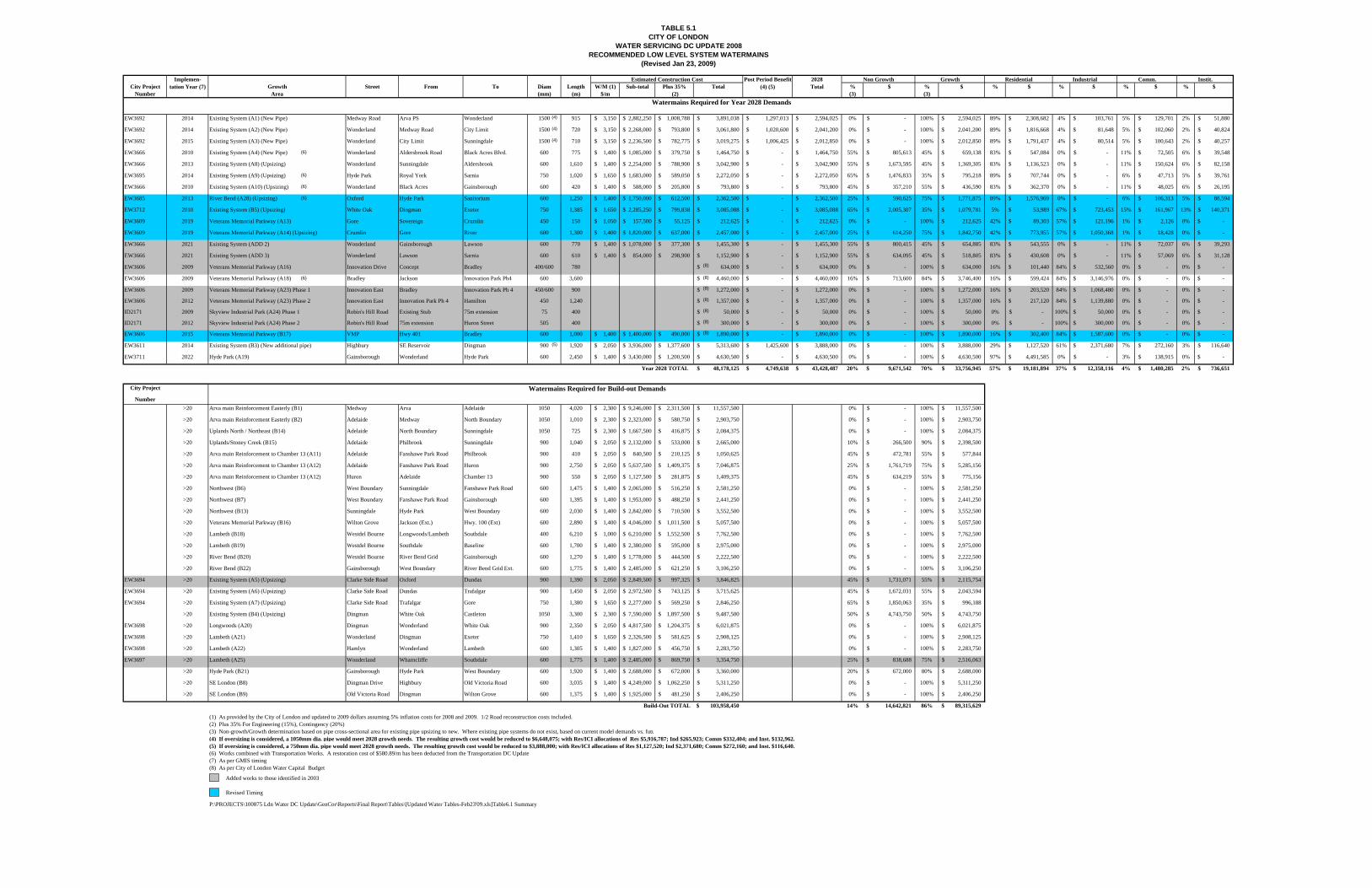
Tables 5.1 and 5.2 identify the future low and high level watermains required respectively for future 2028
and Build-out conditions. Each table shows:
• Location (Growth area, component ID, street and from/to), and applicable details (diameter [mm];
length [m]), for each watermain;
• Estimated cost information (pipe, construction, road restoration, engineering, contingency
oversizing).
Also shown are project implementations in annual or 5 year increments as per GMIS outputs, with the
City’s Water Capital Budget project accounts as provided. All works are identified by timing based on
either Year 2028 or Build-out demand conditions, with Residential and ICI growth, and non-growth
components to 2028, and only growth/non-growth for Build-out for oversizing purposes.
Watermain costs are based on updated pipe and construction tendered costs over the last 4 years to 2007.
Road restoration costs are those used for the London Sanitary DC Update for one lane replacement in
urban and/or rural environments to 2009. Redundancies with other transportation, storm drainage or
sanitary sewer works were removed where applicable. To these costs, engineering at 15% and
contingency at 20%, and indexing from 2007 to 2009 at 5.0% per year was added. Details follow by
growth area with references to Tables 5.1 and 5.2.
City Project Growth Street From To Diam Length W/M (1) Sub-total Plus 35% Total % $ % $ % $ % $ % $ % $Number Area (mm) (m) $/m (2) (3) (3)
EW3692 2014 Existing System (A1) (New Pipe) Medway Road Arva PS Wonderland 1500 915 3,150$ 2,882,250$ 1,008,788$ 3,891,038$ 1,297,013$ 2,594,025$ 0% -$ 100% 2,594,025$ 89% 2,308,682$ 4% 103,761$ 5% 129,701$ 2% 51,880$
EW3692 2014 Existing System (A2) (New Pipe) Wonderland Medway Road City Limit 1500 720 3,150$ 2,268,000$ 793,800$ 3,061,800$ 1,020,600$ 2,041,200$ 0% -$ 100% 2,041,200$ 89% 1,816,668$ 4% 81,648$ 5% 102,060$ 2% 40,824$
EW3692 2015 Existing System (A3) (New Pipe) Wonderland City Limit Sunningdale 1500 710 3,150$ 2,236,500$ 782,775$ 3,019,275$ 1,006,425$ 2,012,850$ 0% -$ 100% 2,012,850$ 89% 1,791,437$ 4% 80,514$ 5% 100,643$ 2% 40,257$
EW3666 2010 Existing System (A4) (New Pipe) Wonderland Aldersbrook Road Black Acres Blvd. 600 775 1,400$ 1,085,000$ 379,750$ 1,464,750$ -$ 1,464,750$ 55% 805,613$ 45% 659,138$ 83% 547,084$ 0% -$ 11% 72,505$ 6% 39,548$
EW3666 2013 Existing System (A8) (Upsizing) Wonderland Sunningdale Aldersbrook 600 1,610 1,400$ 2,254,000$ 788,900$ 3,042,900$ -$ 3,042,900$ 55% 1,673,595$ 45% 1,369,305$ 83% 1,136,523$ 0% -$ 11% 150,624$ 6% 82,158$
EW3695 2014 Existing System (A9) (Upsizing) Hyde Park Royal York Sarnia 750 1,020 1,650$ 1,683,000$ 589,050$ 2,272,050$ -$ 2,272,050$ 65% 1,476,833$ 35% 795,218$ 89% 707,744$ 0% -$ 6% 47,713$ 5% 39,761$
EW3666 2010 Existing System (A10) (Upsizing) Wonderland Black Acres Gainsborough 600 420 1,400$ 588,000$ 205,800$ 793,800$ -$ 793,800$ 45% 357,210$ 55% 436,590$ 83% 362,370$ 0% -$ 11% 48,025$ 6% 26,195$
EW3685 2013 River Bend (A28) (Upsizing) Oxford Hyde Park Sanitorium 600 1,250 1,400$ 1,750,000$ 612,500$ 2,362,500$ -$ 2,362,500$ 25% 590,625$ 75% 1,771,875$ 89% 1,576,969$ 0% -$ 6% 106,313$ 5% 88,594$
EW3712 2010 Existing System (B5) (Upsizing) White Oak Dingman Exeter 750 1,385 1,650$ 2,285,250$ 799,838$ 3,085,088$ -$ 3,085,088$ 65% 2,005,307$ 35% 1,079,781$ 5% 53,989$ 67% 723,453$ 15% 161,967$ 13% 140,371$
EW3609 2019 Veterans Memorial Parkway (A13) Gore Sovereign Crumlin 450 150 1,050$ 157,500$ 55,125$ 212,625$ -$ 212,625$ 0% -$ 100% 212,625$ 42% 89,303$ 57% 121,196$ 1% 2,126$ 0% -$
EW3609 2019 Veterans Memorial Parkway (A14) (Upsizing) Crumlin Gore River 600 1,300 1,400$ 1,820,000$ 637,000$ 2,457,000$ -$ 2,457,000$ 25% 614,250$ 75% 1,842,750$ 42% 773,955$ 57% 1,050,368$ 1% 18,428$ 0% -$
EW3666 2021 Existing System (ADD 2) Wonderland Gainsborough Lawson 600 770 1,400$ 1,078,000$ 377,300$ 1,455,300$ -$ 1,455,300$ 55% 800,415$ 45% 654,885$ 83% 543,555$ 0% -$ 11% 72,037$ 6% 39,293$
EW3666 2021 Existing System (ADD 3) Wonderland Lawson Sarnia 600 610 1,400$ 854,000$ 298,900$ 1,152,900$ -$ 1,152,900$ 55% 634,095$ 45% 518,805$ 83% 430,608$ 0% -$ 11% 57,069$ 6% 31,128$
EW3606 2009 Veterans Memorial Parkway (A16) Innovation Drive Concept Bradley 400/600 780 634,000$ -$ 634,000$ 0% -$ 100% 634,000$ 16% 101,440$ 84% 532,560$ 0% -$ 0% -$
EW3606 2009 Veterans Memorial Parkway (A18) Bradley Jackson Innovation Park Ph4 600 3,600 4,460,000$ -$ 4,460,000$ 16% 713,600$ 84% 3,746,400$ 16% 599,424$ 84% 3,146,976$ 0% -$ 0% -$
EW3606 2009 Veterans Memorial Parkway (A23) Phase 1 Innovation East Bradley Innovation Park Ph 4 450/600 900 1,272,000$ -$ 1,272,000$ 0% -$ 100% 1,272,000$ 16% 203,520$ 84% 1,068,480$ 0% -$ 0% -$
EW3606 2012 Veterans Memorial Parkway (A23) Phase 2 Innovation East Innovation Park Ph 4 Hamilton 450 1,240 1,357,000$ -$ 1,357,000$ 0% -$ 100% 1,357,000$ 16% 217,120$ 84% 1,139,880$ 0% -$ 0% -$
ID2171 2009 Skyview Industrial Park (A24) Phase 1 Robin's Hill Road Existing Stub 75m extension 75 400 50,000$ -$ 50,000$ 0% -$ 100% 50,000$ 0% -$ 100% 50,000$ 0% -$ 0% -$
ID2171 2012 Skyview Industrial Park (A24) Phase 2 Robin's Hill Road 75m extension Huron Street 505 400 300,000$ -$ 300,000$ 0% -$ 100% 300,000$ 0% -$ 100% 300,000$ 0% -$ 0% -$
EW3606 2015 Veterans Memorial Parkway (B17) VMP Hwy 401 Bradley 600 1,000 1,400$ 1,400,000$ 490,000$ 1,890,000$ -$ 1,890,000$ 0% -$ 100% 1,890,000$ 16% 302,400$ 84% 1,587,600$ 0% -$ 0% -$
EW3611 2014 Existing System (B3) (New additional pipe) Highbury SE Reservoir Dingman 900 1,920 2,050$ 3,936,000$ 1,377,600$ 5,313,600$ 1,425,600$ 3,888,000$ 0% -$ 100% 3,888,000$ 29% 1,127,520$ 61% 2,371,680$ 7% 272,160$ 3% 116,640$
EW3711 2022 Hyde Park (A19) Gainsborough Wonderland Hyde Park 600 2,450 1,400$ 3,430,000$ 1,200,500$ 4,630,500$ -$ 4,630,500$ 0% -$ 100% 4,630,500$ 97% 4,491,585$ 0% -$ 3% 138,915$ 0% -$
Year 2028 TOTAL 48,178,125$ 4,749,638$ 43,428,487$ 20% 9,671,542$ 70% 33,756,945$ 57% 19,181,894$ 37% 12,358,116$ 4% 1,480,285$ 2% 736,651$
City Project
Number>20 Arva main Reinforcement Easterly (B1) Medway Arva Adelaide 1050 4,020 2,300$ 9,246,000$ 2,311,500$ 11,557,500$ 0% -$ 100% 11,557,500$
>20 Arva main Reinforcement Easterly (B2) Adelaide Medway North Boundary 1050 1,010 2,300$ 2,323,000$ 580,750$ 2,903,750$ 0% -$ 100% 2,903,750$
>20 Uplands North / Northeast (B14) Adelaide North Boundary Sunningdale 1050 725 2,300$ 1,667,500$ 416,875$ 2,084,375$ 0% -$ 100% 2,084,375$
>20 Uplands/Stoney Creek (B15) Adelaide Philbrook Sunningdale 900 1,040 2,050$ 2,132,000$ 533,000$ 2,665,000$ 10% 266,500$ 90% 2,398,500$
>20 Arva main Reinforcement to Chamber 13 (A11) Adelaide Fanshawe Park Road Philbrook 900 410 2,050$ 840,500$ 210,125$ 1,050,625$ 45% 472,781$ 55% 577,844$
>20 Arva main Reinforcement to Chamber 13 (A12) Adelaide Fanshawe Park Road Huron 900 2,750 2,050$ 5,637,500$ 1,409,375$ 7,046,875$ 25% 1,761,719$ 75% 5,285,156$
>20 Arva main Reinforcement to Chamber 13 (A12) Huron Adelaide Chamber 13 900 550 2,050$ 1,127,500$ 281,875$ 1,409,375$ 45% 634,219$ 55% 775,156$
>20 Northwest (B6) West Boundary Sunningdale Fanshawe Park Road 600 1,475 1,400$ 2,065,000$ 516,250$ 2,581,250$ 0% -$ 100% 2,581,250$
>20 Northwest (B7) West Boundary Fanshawe Park Road Gainsborough 600 1,395 1,400$ 1,953,000$ 488,250$ 2,441,250$ 0% -$ 100% 2,441,250$
>20 Northwest (B13) Sunningdale Hyde Park West Boundary 600 2,030 1,400$ 2,842,000$ 710,500$ 3,552,500$ 0% -$ 100% 3,552,500$
>20 Veterans Memorial Parkway (B16) Wilton Grove Jackson (Ext.) Hwy. 100 (Ext) 600 2,890 1,400$ 4,046,000$ 1,011,500$ 5,057,500$ 0% -$ 100% 5,057,500$
>20 Lambeth (B18) Westdel Bourne Longwoods/Lambeth Southdale 400 6,210 1,000$ 6,210,000$ 1,552,500$ 7,762,500$ 0% -$ 100% 7,762,500$
>20 Lambeth (B19) Westdel Bourne Southdale Baseline 600 1,700 1,400$ 2,380,000$ 595,000$ 2,975,000$ 0% -$ 100% 2,975,000$
>20 River Bend (B20) Westdel Bourne River Bend Grid Gainsborough 600 1,270 1,400$ 1,778,000$ 444,500$ 2,222,500$ 0% -$ 100% 2,222,500$
>20 River Bend (B22) Gainsborough West Boundary River Bend Grid Ext. 600 1,775 1,400$ 2,485,000$ 621,250$ 3,106,250$ 0% -$ 100% 3,106,250$
EW3694 >20 Existing System (A5) (Upsizing) Clarke Side Road Oxford Dundas 900 1,390 2,050$ 2,849,500$ 997,325$ 3,846,825$ 45% 1,731,071$ 55% 2,115,754$
EW3694 >20 Existing System (A6) (Upsizing) Clarke Side Road Dundas Trafalgar 900 1,450 2,050$ 2,972,500$ 743,125$ 3,715,625$ 45% 1,672,031$ 55% 2,043,594$
EW3694 >20 Existing System (A7) (Upsizing) Clarke Side Road Trafalgar Gore 750 1,380 1,650$ 2,277,000$ 569,250$ 2,846,250$ 65% 1,850,063$ 35% 996,188$
>20 Existing System (B4) (Upsizing) Dingman White Oak Castleton 1050 3,300 2,300$ 7,590,000$ 1,897,500$ 9,487,500$ 50% 4,743,750$ 50% 4,743,750$
EW3698 >20 Longwoods (A20) Dingman Wonderland White Oak 900 2,350 2,050$ 4,817,500$ 1,204,375$ 6,021,875$ 0% -$ 100% 6,021,875$
EW3698 >20 Lambeth (A21) Wonderland Dingman Exeter 750 1,410 1,650$ 2,326,500$ 581,625$ 2,908,125$ 0% -$ 100% 2,908,125$
EW3698 >20 Lambeth (A22) Hamlyn Wonderland Lambeth 600 1,305 1,400$ 1,827,000$ 456,750$ 2,283,750$ 0% -$ 100% 2,283,750$
EW3697 >20 Lambeth (A25) Wonderland Wharncliffe Southdale 600 1,775 1,400$ 2,485,000$ 869,750$ 3,354,750$ 25% 838,688$ 75% 2,516,063$
>20 Hyde Park (B21) Gainsborough Hyde Park West Boundary 600 1,920 1,400$ 2,688,000$ 672,000$ 3,360,000$ 20% 672,000$ 80% 2,688,000$
>20 SE London (B8) Dingman Drive Highbury Old Victoria Road 600 3,035 1,400$ 4,249,000$ 1,062,250$ 5,311,250$ 0% -$ 100% 5,311,250$
>20 SE London (B9) Old Victoria Road Dingman Wilton Grove 600 1,375 1,400$ 1,925,000$ 481,250$ 2,406,250$ 0% -$ 100% 2,406,250$
Build-Out TOTAL 103,958,450$ 14% 14,642,821$ 86% 89,315,629$
(1) As provided by the City of London and updated to 2009 dollars assuming 5% inflation costs for 2008 and 2009. 1/2 Road reconstruction costs included. (2) Plus 35% For Engineering (15%), Contingency (20%)(3) Non-growth/Growth determination based on pipe cross-sectional area for existing pipe upsizing to new. Where existing pipe systems do not exist, based on current model demands vs. futu(4) If oversizing is considered, a 1050mm dia. pipe would meet 2028 growth needs. The resulting growth cost would be reduced to $6,648,075; with Res/ICI allocations of Res $5,916,787; Ind $265,923; Comm $332,404; and Inst. $132,962.(5) If oversizing is considered, a 750mm dia. pipe would meet 2028 growth needs. The resulting growth cost would be reduced to $3,888,000; with Res/ICI allocations of Res $1,127,520; Ind $2,371,680; Comm $272,160; and Inst. $116,640.(6) Works combined with Transportation Works. A restoration cost of $580.89/m has been deducted from the Transportation DC Update(7) As per GMIS timing(8) As per City of London Water Capital Budget
P:\PROJECTS\100875 Ldn Water DC Update\GenCor\Reports\Final Report\Tables\[Updated Water Tables-Feb23'09.xls]Table6.1 Summary
Comm.
(Revised Jan 23, 2009)
TABLE 5.1CITY OF LONDON
WATER SERVICING DC UPDATE 2008RECOMMENDED LOW LEVEL SYSTEM WATERMAINS
Implemen- tation Year (7)
Watermains Required for Build-out Demands
Residential IndustrialPost Period Benefit (4) (5)
2028 Total
Non Growth Growth
Watermains Required for Year 2028 Demands
Estimated Construction Cost Instit.
Added works to those identified in 2003
(4)
(4)
(4)
(5)
Revised Timing
(6)
(6)
(6)
(6)
(6)
(8)
(8)
(8)
(8)
(8)
(8)
(8)

CITY PROJECT NUMBER
IMPL'T YEAR (5)
GROWTH AREAS COMPONENT STREET FROM TO DIAM LENGTH (%)(3) $ (%)(3) $
(mm) (m)W'main (2)
$/m Sub-Total Plus 35% TotalPost Period
Benefit 2028 Total %(1) $ %(1) $ %(1) $ %(1) $
2011 2018 Byron Baseline Wickerson Westdel Bourne 450 656 $ 1,050 $ 688,800 $ 241,080 $ 929,880 $ - $ 929,880 0% -$ 100% 929,880$ 99% 920,581$ 0% -$ 1% 9,299$ 0% -$
EW3652 2011 River Bend 2019 Westdel Bourne Byron Baseline Mid. Westdel Bourne 450 792 $ 1,050 $ 831,600 $ 291,060 $ 1,122,660 $ - $ 1,122,660 0% -$ 100% 1,122,660$ 99% 1,111,433$ 0% -$ 1% 11,227$ 0% -$
2011 2020 Westdel Bourne Mid Westdel Bourne Oxford 400 752 $ 1,000 $ 752,000 $ 263,200 $ 1,015,200 $ - $ 1,015,200 0% -$ 100% 1,015,200$ 99% 1,005,048$ 0% -$ 1% 10,152$ 0% -$
2017 2021/2022 Oxford Westdel Bourne Kains 400 868 $ 1,000 $ 868,000 $ 303,800 $ 1,171,800 $ - $ 1,171,800 0% -$ 100% 1,171,800$ 99% 1,160,082$ 0% -$ 1% 11,718$ 0% -$
2016 2028 Sarnia West of Deer Ridge Hyde Park 400 720 $ 1,000 $ 720,000 $ 252,000 $ 972,000 $ - $ 972,000 0% -$ 100% 972,000$ 97% 942,840$ 0% -$ 3% 29,160$ 0% -$
2015 2032 Hyde Park Sarnia South Carriage 450 850 $ 1,050 $ 892,500 $ 312,375 $ 1,204,875 $ - $ 1,204,875 0% -$ 100% 1,204,875$ 97% 1,168,729$ 0% -$ 3% 36,146$ 0% -$
2022 2033 Gainsborough Coronation Aldersbrook 600 360 $ 1,400 $ 504,000 $ 176,400 $ 680,400 $ - $ 680,400 0% -$ 100% 680,400$ 97% 659,988$ 0% -$ 3% 20,412$ 0% -$
Year 2028 Totals 5,256,900$ 1,839,915$ 7,096,815$ -$ $7,096,815 0% -$ 100% 7,096,815$ 98% $6,968,701 0% -$ 2% 128,114$ 0% -$
Watermains Required for Build-out and Ultimate Build-out Demands
EW3699 >20 South London 2017 Boler Southdale Pack 450 2,057 $ 1,050 $ 2,159,850 $ 755,948 $ 2,915,798 0% -$ 100% 2,915,798$ 0% -$ 100% 2,915,798$ 0% -$ 0% -$
EW3699 >20 South London 2004/2005 Southdale Bramblewood Wickerson 450 1,050 $ 1,050 $ 1,102,500 $ 385,875 $ 1,488,375 0% -$ 100% 1,488,375$ 99% 1,473,491$ 0% -$ 1% 14,884$ 0% -$
EW3652 >20 River Bend 2006 Wickerson Southdale Mid Wickerson 450 970 $ 1,050 $ 1,018,500 $ 356,475 $ 1,374,975 0% -$ 100% 1,374,975$ 99% 1,361,225$ 0% -$ 1% 13,750$ 0% -$
Buildout Totals 4,280,850$ 1,498,298$ 5,779,148$ 0% -$ 100% 5,779,148$ 49% 2,834,717$ 50% 2,915,798$ 0% 28,634$ 0% -$
(1) From City of London Water Master Plan Update. Reconfirmed as part of this work. (2) Costs updated from (1) with latest tender unit cost information (2007, inflated to 2009 dollars), plus Engineering and Contingency at 35%. 1/2 Road restoration costs included.(3) Based on Existing Versus Future Service Area Demand and/or Pipe Size Cross-Sectional Area Differential (whichever is more applicable).(4) Works combined with Transportation Works. A restoration cost of $526.89/m has been deducted from the Transportation DC Update(5) As per GMIS timing
P:\PROJECTS\100875 Ldn Water DC Update\GenCor\Reports\Final Report\Tables\[Updated Water Tables-Feb23'09.xls]Table6.1 Summary
ESTIMATED CONSTRUCTION COST Commercial
NON GROWTH GROWTH
Institutional
Hyde ParkEW3651
TABLE 5.2CITY OF LONDON
WATER SERVICING DC UPDATE 2008HIGH LEVEL SYSTEM WATERMAIN COMPONENTS
(Revised Jan 23, 2009)
Residential Industrial
REQUIRED WATERWORKS (1)
Revised Timing
(4)

!(
!(
!(
!(
!(
!(
!(
!(.
WATER SERVICINGDC UPDATE 2008
FIGURE 5.1
WATER WORKSTO YEAR 2028
SCALE: N.T.S
DATE: FEB 2009 PN: 100875
1500
1500
1500
600
750
600
900
600
600
450
400
400
450
450
400
600
750
600
600
]
LHWSS SUPPLY
450
]EAWSS SUPPLY
(91/182 MLD)
ARVA PS & RESERVOIR
UPLANDS PS
WESTMOUNT PS
SPRINGBANK PS & RESERVOIRWICKERSON PS
HYDE PARK PS
PROPOSED SOUTHEAST PS& RESERVOIR
A1
A2
A3
A8
A4
A10
2028
2033
2032
A9
A28
2021/2022
2020
2019
2018
B5
B3
A18
B17
A13
A19600
LegendMajor Roads
City Boundary
WatermainsLow Pressure ZoneHigh Pressure Zone
GMIS Boundary
Urban Growth Boundary
Existing Watermains > 300 mm Dia.
Southeast Zone
Future Southeast Service Area
Watermain DiameterComponent ID
900
2020/A25
Waterways
Existing Built Out City
A23 45
0
600
600
AD
D3
AD
D2
A14
600
Pump Station!(
PONDMILLS PS
600
A16
400A
24
600

!(
!(
!(
!(
!(
!(
!(
!(
PONDMILLS PS
ARVA PS & RESERVOIR
UPLANDSPS
PROPOSED SOUTHEAST PSAND RESERVOIR
WESTMOUNT PS
WICKERSON PS
HYDE PARK PS
SPRINGBANK PS & RESERVOIR
WATER SERVICINGDC UPDATE 2008
FIGURE 5.2
WATER WORKS TO BUILD OUT(675,000 Population)
SCALE: N.T.S
DATE: FEB 2009 PN: 100875
LegendMajor Roads
City Boundary
Existing Built Out City
Urban Growth Boundary
Future Southeast Service Area
.
600
750
900
900
1500
1500
1500
600
750
600
900
600
600
600
450
450
450
40040
0
450
450
450
450
450
400
600
600
600
600
600
600
600
400
400
600400
9001050
750
600
A12
A12
A11
/B15
B14
B21050
900
600
600
600
600
LHWSS SUPPLY
EAWSS SUPPLY(91/182 MLD)
Component IDWatermain Diameter900
2020/A25
A1
A2
A3
A8
A4
A10
2032
2033
2028
B13
B6
B7
B21B22
B20
A9
A28
2021/2022
2020
2019
2018
2006
2005/2004
B19
B18
B18
B18 A22
2017
A20
B4
B5A21
A25
B3
B16
A18
B17
A14
A13
A7
A6
A5
B1
1050
1050
900
900
900
A12
WatermainsLow Pressure ZoneHigh Pressure ZoneBuild Out - Low Pressure ZoneSoutheast ZoneExisting Watermains > 300 mm Dia.
600 A19
600
B8 B9
600
Waterways
Ultimate Build Out Boundary(675,000 Population)
GMIS Boundary
]
]
A23 45
0
600
600 A
DD
2A
DD
3
400A16
400
A24
600

Water Servicing Development Charge Update 2008 Page 17
The Corporation of the City of London AECOM
Project No. 100875
Growth/Non-Growth determinations and Res/ICI allocations are discussed in Section 6. Most of the
works required to 2028 and Build-out are as per those identified in the 2003 Water Master Plan Update
completed by AECOM (formerly Earth Tech). Additions as a result of this work are highlighted in grey
in Tables 5.1 and 5.2.
5.1.1. Existing System Reinforcements
Several of the watermain replacements required (upsizing and/or twinning), were identified in the Water
Master Plan Update 2003 previously. These include:
Year 2028
• Medway Road, and Wonderland Road to Sunningdale Road from the Arva Pumping Station (Items A1, A2 and A3). Each are required to service future growth needs 100%.
• Wonderland Road – Sunningdale Road to Gainsborough Road (Items A4, A8 and A10). Each of these works require upsizing (or twinning), of the existing watermains in place due to growth (A8 and A10), or to address existing deficiencies (A4), to allow A8, A10, ADD2 and ADD3 to service future growth.
• Gainsborough Road – Wonderland Road to Hyde Park (Item A19). This watermain is needed to service future growth 100% due to transfer of the existing low level watermain to high pressure servicing. Although low level servicing is provided early on in the period, due to the transfer, it cannot be sustained over the long term as growth in the Hyde Park area and West London continues.
• Skyview Industrial Park – Robin’s Hill Road from the existing stub to Huron Street (Item A24) to complete watermain looping for the Skyview Industrial Park and required to service future growth needs 100%.
• Highbury Avenue – A new additional pipe from the proposed Southeast PS and Reservoir to Dingman Drive (Item B3), is required. This is required to service future growth (100%), in the last 10 years of the growth period.
• White Oak Road – Dingman Drive to Exeter Road (Item B5). Upsizing (or twinning), of the existing watermain is required to service future growth.
Pressure and/or headloss criteria problems were also identified through modeling within the existing
watermains on Highbury Avenue between Dundas Street and Huron Street. These do not appear to be
driven by growth needs, but rather by existing conditions and C-factor degradation. This information was
relayed to the City of London for them to follow-up with regards to the Infrastructure Needs Study.

Water Servicing Development Charge Update 2008 Page 18
The Corporation of the City of London AECOM
Project No. 100875
Deficiencies were also noted within the City’s high pressure water system in the Wonderland
Road/Viscount Road area of the City (Items 3000 to 3005). These watermains require upsizing (or
twinning), to rectify existing deficiencies in this service area. They are therefore 100% non-growth
related. See Table 5.2 for details.
Build-out
Arva Main Reinforcement (East) – Medway Road (Arva PS to Adelaide Street), and Adelaide Street
(Medway Road to Sunningdale Road) (Items B1, B2 and B14). These are 100% growth driven.
Arva main reinforcing on Adelaide Street – Sunningdale Road to Huron Street – Chamber 13 (Items
A11, A12 and B15). Upsizing (or twinning), of the existing watermains are required to service
future growth.
Dingman Drive – Caselton to White Oak Road (Item B4). Upsizing (or twinning), of the existing
watermains is required to service future growth.
Clarke Road – Oxford Street to Gore Road (Items A5, A6 and A7). Upsizing (or twinning), of the
existing watermain is required to service future growth.
5.1.2. North London
The Fox Hollow, Sunningdale, Uplands, Stoney Creek and Kilally Community planning areas (North and
South), and Northeast and Northwest London are expected to consist primarily of residential
development.
For the Year 2028, north London will be serviced via the existing trunk watermain on Sunningdale Road.
Based on the Community Planning information provided to date, these areas can be serviced internally via
watermains less than 400 mm (16”) in diameter.
Northwest London was considered further as part of the Build-out scenario. Under these conditions, a
new trunk watermain along Sunningdale Road from Hyde Park Road west (Item B13), and then south to
the future Gainsborough Road extension (Items B6 and B7), discussed in Section 5.1.6, is required. The
need for these works will depend upon future internal servicing for this area specifically. Watermains
400 mm (16”) in diameter or greater may be needed to accomplish the objective of supplying water to
west London, to approximately Southdale Road from the Arva PS.

Water Servicing Development Charge Update 2008 Page 19
The Corporation of the City of London AECOM
Project No. 100875
Watermain sizing to the City’s Northeast and Northwest was reduced to the extent possible based on the
premise that internal servicing between Sunningdale Road and the City boundary via watermains less than
400 mm (16”) in diameter can be provided. This will assist in the supply of flows to the City’s east and
west sides. This should be confirmed once servicing for those areas north of Sunningdale Road to
the City limit has been identified.
Portions of north London are also at high elevation and receive boosted pressure servicing via the
previously expanded Uplands Pumping Station. Details were initially provided in the City of London
Community Plans Water Services Supply Study Report for Fox Hollow, Sunningdale, Uplands and
Stoney Creek completed by Knowles Engineering Inc. (2000). This was confirmed and updated as part of
the Uplands PS EA and Pre-Design report by AECOM (formerly Earth Tech) in 2002.
The Kilally North and East areas can be serviced from the existing watermains in place on Highbury
Avenue and Fanshawe Road. It has been assumed that internal watermains less than 400 mm (16”) in
diameter can service these areas as per the Kilally North and South community planning reports. The
same applies in the Cheapside and Skyway areas in the City’s northeast also, as per the servicing reports
for these areas.
5.1.3. Veterans Memorial Parkway East Area
This area is primarily industrial in nature where little growth is projected. This area can be serviced from
existing watermains on Clarke Road. It has been assumed that internal servicing can be provided via
watermains less than 400 mm (16”) in diameter for this area to avoid the need for major works.
5.1.4. Southeast London
This area is expected to be primarily industrial in nature (Veterans Memorial Parkway, Highbury/401),
with the exception of the Commissioners Road/Jackson Road area (Summerside East), which is expected
to be residential. This area is to be serviced by the proposed Southeast Pumping Station and Reservoir.
Using the service level/design criteria outlined in Table 3.1, and that utilized for design purposes in small
areas, modeling for specific scenarios to service this area was completed. This included:
• Servicing from the existing low level watermain systems in the area to the extent possible;
• Servicing via high pressure servicing from the Elgin-Middlesex and Pond Mills Pumping Stations; and

Water Servicing Development Charge Update 2008 Page 20
The Corporation of the City of London AECOM
Project No. 100875
• Future servicing based on construction and operation of the Southeast Reservoir and Pumping Station, were reviewed.
The outputs formed the basis for the watermain needs identified for this area to 2028, and for Build-out.
To 2028, watermains will be required: on Commissioners Road, Jackson Road to Veterans Memorial
Parkway; on Veterans Memorial Parkway from the Thames River south to Highway 401; on Crumlin
Road, north of the Thames River to Gore Road; and on Bradley Avenue between Jackson Road and
Veterans Memorial Parkway. A small portion of new watermain on Gore Road between Crumlin Road
and Sovereign Court would be needed to service some growth potential north of the Thames River, east of
Veterans Memorial Parkway (Item No’s A13, A14, A16, A18, A23 and B17). All are 100% growth
related to serve primarily proposed industrial development in Southeast London.
For Build-out, watermains will be required: on Veterans Memorial Parkway south of the 401; on Wilton
Grove Road, from Veterans Memorial Parkway to Cheese Factory Road: on Dingman Drive from Old
Victoria Road to Highbury Avenue; and on Old Victoria Road from Wilton Grove Road to Dingman
Drive. (Items B8, B9, B16 and the rest of B17). Each of these work are 100% growth driven.
Some or all of these watermain components may have to be accelerated to some extent in the event:
a) a heavy water user is located in the Veterans Memorial Parkway south study area; or
b) servicing is to be provided to Thames Centre via either watermain extensions east along Commissioners Road, or east along Bradley Avenue.
This is based on the premise of providing 7.8 MLD (MDD), to Thames Centre as per the information they
provided dated May 17, 2004.
5.1.5. South London
The Brockley, Longwoods, Bostwick, Talbot and existing Lambeth areas are located in south London.
They are expected to consist of a mixture of residential, commercial and industrial land uses. These areas
will for the most part, be serviced from the future Southeast Reservoir and Pumping Station. The
northern portion of the Talbot planning area is/will continue to be serviced by the Springbank PS.
The Brockley area can be serviced from the existing trunk watermain on Dingman Drive to 2028.
The Dingman Drive watermain would be extended from White Oak Road to Lambeth to service the
southern portion of the Longwoods area (Item A20), and existing Lambeth (looped supply) under Build-
Water Servicing Development Charge Update 2008 Page 21
The Corporation of the City of London AECOM
Project No. 100875
out conditions. The watermains proposed on Wonderland Road and Hamlyn Street (Items A21 and A22),
and on Longwoods Road and Westdel Bourne to Baseline Road (Items B18 and B19) will also supply
water to Southwest London for the Build-out scenario. It will also allow for the transfer of flows between
the Arva and Southeast supplied systems under emergency conditions.
The watermain proposed on Wonderland Road from Wharncliffe to Southdale Road (Item A25) will
service internal portions of the Bostwick and Longwoods areas to the west and east for Build-out.
Growth projected to 2028 for the Longwoods, Bostwick and Lambeth areas can be serviced by the
existing watermains in this area, with the exception of a portion of the Talbot planning area (east side).
This area would be serviced by the City’s high level system from the Springbank Pumping Station. The
southern portion of the Talbot planning area can be serviced from the existing watermains on Colonel
Talbot Road and Southdale Road. An extension to Boler Road from Colonel Talbot, Southdale Road
from Bramblewood Place to Wickerson Road and Wickerson Road from Southdale Road to the exisiting
on Wickerson Road (Items 2004, 2005, 2006 and 2017) are required under the Build-out scenario to link
the existing Springbank PS and future Wickerson PS high pressure service areas.
5.1.6. West London
The RiverBend, Wickerson Road and Hyde Park Road areas are expected to be primarily residential in
nature.
The RiverBend area will be serviced to 2028 by the existing watermain on Westdel Bourne Road from
Baseline Road to Shore Road, and the upsizing (or twinning), required on Oxford Street from Hyde Park
Road to Sanitorium Road (Item A28), and on Hyde Park Road from Sarnia Road to Oxford Street (Item
A9). For Build-out, this watermain extension would continue north to Gainsborough Road to complete
looping and provide additional supply capacity from Arva to west London (Items B20, B21 and B22),
connecting to Item B7 and Hyde Park Road. These works are all 100% growth driven.
The southern portion of the RiverBend and the Wickerson area are serviced by the Wickerson Pumping
Station and related high level watermains to be constructed on Wickerson Road, from Base Line Road to
Southdale Road; on Southdale Road from Wickerson Road east to Bramblewood Road; on Base Line
Road from Wickerson Road to Westdel Bourne; on Westdel Bourne between Base Line and Oxford
Street, and on Oxford Street east to Commissioners Road (Items 2018 to 2022). All of these watermains
are 100% growth driven.

Water Servicing Development Charge Update 2008 Page 22
The Corporation of the City of London AECOM
Project No. 100875
Growth in the Hyde Park area would be serviced by the City’s high level system fed by the Hyde Park
Pumping Station. This includes high level watermains on Gainsborough Road from Fanshawe Park Road
to Aldersbrook; on Hyde Park Road from Gainsborough Road to Sarnia Road; and on Sarnia Road from
Hyde Park Road to Barrydale (Items 2028, 2032 and 2033).
5.2. Facility Related Works In addition to the watermain related works, facility related works are also required for the City’s water
distribution system, and for the EAWS/EMW and LHWS Systems. The City water system includes
implementation of the Southeast Reservoir and Pumping Station.
Master planning for the LHWS/EAWS systems was last completed in 2003 and is currently being
updated. The 2003 report was used as an input to this update along with City budget updates.
These details are subject to review and confirmation by the Joint Board of Management for each
water system and the general public through consultation.
Table 5.3 A/B identifies the facility related works required for the City, Elgin and Lake Huron water
systems. Identified is the facility by name; approximate implementation year as per our work or GMIS
outputs; existing rated capacity and current flows (2007); future flow requirements to 2028; and
new/expansion capacity information; and estimated costs from study, other report or City budget/GMIS
sources. City facility related costs were updated to 2009 to which engineering at 15% and contingency at
20% were added. For the LHWSS/EAWSS components, City provided budget information was used.
City project numbers are identified as provided. Also shown are the non-growth and growth components
applicable to City of London and/or to Elgin Area/Lake Huron water system users. Residential and ICI
allocations are also shown. Details are discussed in Section 6 of the report.
Current and future flow requirements developed as part of the Water Master Plan Update 2003 for the
Elgin Area and Lake Huron Water Supply Systems are outlined in Table 5.4. This summarizes outputs
from the Elgin Area and Lake Huron Master Plan updates completed by Stantec Consulting. Identified
are average day winter (ADDw), and Max Day Demands (MDD) in 2002, and future demands (ADDw
and MDD) to 2024. Max Day use was determined utilizing the 1.95 peaking factor for the City of
London. The water demands were determined using the City’s criteria outlined in Section 3 of this report.
Also shown is the net demand increase for a given system or scenario, and the related system capacities in
place, or required to be put in place to address, and any over/under amounts that result. Given the Elgin

CITYGROWTH TO
2028 (11)GROWTH
BEYOND 2028(11)
PROJECT No. FACILITY
IMPLEMENTATION YEAR ADDw MAX DAY ADDw MAX DAY ADDw MAX DAY ADDw MAX DAY PEAK % $ % $ % $ % $ $ % $ % $ % $ % $ $ % $ % $ % $ % $
EW3653 Wickerson PS 2011 0 0 0 0 48L/s 93L/s 57L/s 142L/s 830,000$ 830,000$ 0% -$ 100% 830,000$ 830,000$ 100% 830,000$ 0% -$ 0% -$ 0% -$ -$ 0% -$ 0% -$ 0% -$ 0% -$
EW3590 Uplands PS (12) 2015 30L/s 60L/s 40L/s 45L/s 40.0 45.0 280,000$ 280,000$ 0% -$ 100% 280,000$ 280,000$ 99% 277,200$ 0% -$ 1% 2,800$ 0% -$ -$ 0% -$ 0% -$ 0% -$ 0% -$
EW3591 Hyde Park PS (13) 2015 210L/s 320L/s 300L/s 460L/s 90L/s 140L/s 550,000$ 550,000$ 0% -$ 100% 550,000$ 550,000$ 100% 550,000$ 0% -$ 0% -$ 0% -$ -$ 0% -$ 0% -$ 0% -$ 0% -$
1,660,000$ -$ 1,660,000$ 0% -$ 100% 1,660,000$ 1,660,000$ 100% 1,657,200$ 0% -$ 0% 2,800$ 0% -$ -$ 0% -$ 0% -$ 0% -$ 0% -$
EW3614 Southeast PS (3) 287 L/s (4) 279 l/s 279 l/s 718 l/s 1401 l/s 920 L/s 1794 L/s 2210 L/s 29,600,000$ 94% 27,798,000$ 1,802,000$ 0% -$ 100% 1,802,000$ 1,405,560$ 40% 562,224$ 49% 688,724$ 6% 84,334$ 5% 70,278$ 396,440$ 29% 114,968$ 61% 241,828$ 7% 27,751$ 3% 11,893$ EW3614 Reservoir -43 M/L (5) -60 M/L (5) 113 ML 26,100,000$ 94% 24,530,000$ 1,570,000$ 0% -$ 100% 1,570,000$ 1,570,000$ 56% 879,200$ 32% 502,400$ 5% 78,500$ 7% 109,900$ -$ -$ -$ -$ -$
EW3628Southeast Pressure Zone (14) 2009-2016 2,700,000$ 2,700,000$ 60% 1,620,000$ 40% 1,080,000$ 1,080,000$ 56% 604,800$ 32% 345,600$ 5% 54,000$ 7% 75,600$ -$ -$ -$ -$ -$
58,400,000$ 52,328,000$ 6,072,000$ 27% 1,620,000$ 73% 4,452,000$ 4,055,560$ 50% 2,046,224$ 38% 1,536,724$ 5% 216,834$ 6% 255,778$ 396,440$ 29% 114,968$ 61% 241,828$ 7% 27,751$ 3% 11,893$
EW3654 Arva PS 2020 3680 L/s (6) 5266 L/s (6) 2,600,000$ $ 2,600,000 50% 1,300,000$ 50% 1,300,000$ 1,300,000$ 89% 1,157,000$ 5% 65,000$ 5% 65,000$ 1% 13,000$ -$ 89% -$ 5% -$ 5% -$ 1% -$
2,600,000$ 2,600,000$ 50% 1,300,000$ 1,300,000$ 1,300,000$ 89% 1,157,000$ 5% 65,000$ 5% 65,000$ 1% 13,000$ -$ -$ -$ -$ -$
62,660,000$ 52,328,000$ 10,332,000$ 28% 2,920,000$ 72% 7,412,000$ 7,015,560$ 69% 4,860,424$ 23% 1,601,724$ 4% 284,634$ 4% 268,778$ 396,440$ 29% 114,968$ 61% 241,828$ 7% 27,751$ 3% 11,893$
CITYGROWTH TO
2028(11)GROWTH
BEYOND 2028(11)
PROJECT No. FACILITY
IMPLEMENTATION YEAR ADDw MAX DAY ADDw MAX DAY ADDw MAX DAY ADDw MAX DAY PEAK % $ % $ % $ % $ $ % $ % $ % $ % $ $ % $ % $ % $ % $
EAWSS/EMWS(7)
EA4020 Low Lift PS 2018 42 MLD 91 MLD 24.1+24=48.1 MLD 47+47=94 MLD 32.2+34.9=67.1 MLD 62.8+68.1=130.9 MLD 91 MLD 182 MLD 3,000,000$ 3,000,000$ 0% -$ 52% 1,560,000$ 48% 1,440,000$ 1,036,800$ 29% 300,672$ 61% 632,448$ 7% 72,576$ 3% 31,104$ 403,200$ 29% 116,928$ 61% 245,952$ 7% 28,224$ 3% 12,096$
EA4021Raw Water Transmission Main 2018 42 MLD 91 MLD 24.1+24=48.1 MLD 47+47=94 MLD 32.2+34.9=67.1 MLD 62.8+68.1=130.9 MLD 91 MLD 182 MLD 3,000,000$ 3,000,000$ 0% -$ 52% 1,560,000$ 48% 1,440,000$ 1,036,800$ 29% 300,672$ 61% 632,448$ 7% 72,576$ 3% 31,104$ 403,200$ 29% 116,928$ 61% 245,952$ 7% 28,224$ 3% 12,096$
EA4022 Water Treatment Plant 2018 42 MLD 91 MLD 24.1+24=48.1 MLD 47+47=94 MLD 32.2+34.9=67.1 MLD 62.8+68.1=130.9 MLD 91 MLD 182 MLD 55,000,000$ 55,000,000$ 0% -$ 52% 28,600,000$ 48% 26,400,000$ 19,008,000$ 29% 5,512,320$ 61% 11,594,880$ 7% 1,330,560$ 3% 570,240$ 7,392,000$ 29% 2,143,680$ 61% 4,509,120$ 7% 517,440$ 3% 221,760$
EA4023Residue Management Plant 2011 0 0 24.1+24=48.1 MLD 47+47=94 MLD 32.2+34.9=67.1 MLD 62.8+68.1=130.9 MLD 91 MLD 182 MLD 13,250,000$ 57% 7,552,500$ 5,697,500$ 15% 828,125$ 30% 1,689,375$ 56% 3,180,000$ 2,289,600$ 29% 663,984$ 61% 1,396,656$ 7% 160,272$ 3% 68,688$ 890,400$ 29% 258,216$ 61% 543,144$ 7% 62,328$ 3% 26,712$
EA4024Treated Water Transmission Main (New) 2011 42 MLD 82 MLD 24.1+24=48.1 MLD 47+47=94 MLD 32.2+34.9=67.1 MLD 62.8+68.1=130.9 MLD 91 MLD 182 MLD 23,150,000$ 57% 13,195,500$ 9,954,500$ 0% -$ 0% -$ 100% 9,954,500$ 7,167,240$ 29% 2,078,500$ 61% 4,372,016$ 7% 501,707$ 3% 215,017$ 2,787,260$ 29% 808,305$ 61% 1,700,229$ 7% 195,108$ 3% 83,618$
97,400,000$ 20,748,000$ 76,652,000$ 828,125$ 33,409,375$ 42,414,500$ 30,538,440$ 8,856,148$ 18,628,448$ 2,137,691$ 916,153$ 11,876,060$ 3,444,057$ 7,244,397$ 831,324$ 356,282$
Elgin Middlesex PS >20 68 MLD 24.1+24=48.1 MLD 47+47=94 MLD 32.2+34.9=67.1 MLD 62.8+68.1=130.9 MLD 158 MLD 2,130,000$ 2,130,000$ 0% -$ 0% -$ 100% 2,130,000$ -$ 0% -$ 0% -$ 0% -$ 0% -$ 2,130,000$ 29% 617,700$ 61% 1,299,300$ 7% 149,100$ 3% 63,900$
2,130,000$ -$ 2,130,000$ 0% -$ 0% -$ 100% 2,130,000$ -$ 0% -$ 0% -$ 0% -$ 0% -$ 2,130,000$ 29% 617,700$ 61% 1,299,300$ 7% 149,100$ 3% 63,900$
EAWSS Sub-Total 99,530,000$ 20,748,000$ 78,782,000$ 1% 828,125$ 34% 33,409,375$ 45% 44,544,500$ 30,538,440$ 29% 8,856,148$ 61% 18,628,448$ 7% 2,137,691$ 3% 916,153$ 14,006,060$ 29% 4,061,757$ 61% 8,543,697$ 7% 980,424$ 3% 420,182$
LHWSS (8)
LH1902
Residue Management Facility 2012 0 0 118.9+9.6=128.5 MLD 231.9+18.7=250.6 MLD 152.6+21.2=173.8 MLD 297.5+41.3=338.8 MLD 173 MLD 340 MLD 10,250,000$ 57% 5,842,500$ 4,407,500$ 41% 1,810,390$ 5% 239,610$ 53% 2,357,500$ 2,357,500$ 89% 2,098,175$ 5% 117,875$ 5% 117,875$ 1% 23,575$ -$ 0% -$ 0% -$ 0% -$ 0% -$
LH1305Transmission Main Twinning Completion 2013-2016 (15) 173 MLD 340 MLD 118.9+9.6=128.5 MLD 231.9+18.7=250.6 MLD 152.6+21.2=173.8 MLD 297.5+41.3=338.8 MLD 204 MLD 400 MLD 47,000,000$ 33% 15,447,000$ 31,553,000$ 73% 23,103,414$ 6% 2,009,586$ 20% 6,440,000$ 6,440,000$ 89% 5,731,600$ 5% 322,000$ 5% 322,000$ 1% 64,400$ -$ 0% -$ 0% -$ 0% -$ 0% -$
LH1326 Additional Standby Power 2010 100 MLD 118.9+9.6=128.5 MLD 231.9+18.7=250.6 MLD 152.6+21.2=173.8 MLD 297.5+41.3=338.8 MLD 200 MLD 7,200,000$ 57% 4,104,000$ 3,096,000$ 63% 1,961,379$ 6% 198,621$ 30% 936,000$ 936,000$ 89% 833,040$ 5% 46,800$ 5% 46,800$ 1% 9,360$ -$ 0% -$ 0% -$ 0% -$ 0% -$
64,450,000$ 25,393,500$ 39,056,500$ 42% 26,875,183$ 4% 2,447,817$ 15% 9,733,500$ 9,733,500$ 89% 8,662,815$ 5% 486,675$ 5% 486,675$ 1% 97,335$ -$ 0% -$ 0% -$ 0% -$ 0% -$
163,980,000$ 46,141,500$ 117,838,500$ 17% 27,703,308$ 22% 35,857,192$ 33% 54,278,000$ 40,271,940$ 44% 17,518,963$ 47% 19,115,123$ 7% 2,624,366$ 3% 1,013,488$ 14,006,060$ 29% 4,061,757$ 61% 8,543,697$ 7% 980,424$ 3% 420,182$
(1) London+LHWSS or EAWSS = TOTAL. From City provided growth and modelling demand information. Carried forward from 2004
(2) Estimated costs from background reprots or as provided by the City of London.
(3) From City of London, Southeast Terminal Reservoir and Pumping Station, Preliminary and Detailed design info (Earth Tech) and 2009 City Budget.
(4) Existing Pond Mills PS rated capacity possibly replaced
(5) From London Water Reliability Assessment Final Report; Dillon 2002.
(6) From City of London Water Works Master Plan Update to 2016, Dillon, November 1994.
(7) From EAPWSS Master Plan Update, Stantec Draft July 30, 2003 or per City provided information.
(8) From LHPWSS Master Plan Update, Stantec Draft July 30, 2003 or per City provided information.
(9) Remainder to EAWSS or LHWSS users.
(10) The table reflects expected grant funding, based on best estimates available at the time of preparation of this table. Funding reduced from London-Non Growth and Elgin/LHWSS Users first, then London-Growth.
(11) 2028 flow requirements as a percentage of capacity provided. Difference to Growth Buildout.
(12) Uplands PS Design Brief, 2003
(13) Hyde Park PS Design Brief, 2002 (20yr/Full Buildout components work deleted)
(14) Southeast Reservoir and Pumping Station Design Report, 2005 Table 15.1
(15) Assumed that project will be built in 3 equal phases, more details will be provided once a detailed design is complete.
P:\PROJECTS\100875 Ldn Water DC Update\GenCor\Reports\Final Report\Tables\[Updated Water Tables-Feb23'09.xls]Table6.1 Summary
PRELIMINARY WATER SUPPLY SYSTEM COMPONENTS
GROWTH BEYOND 2028 (POST PERIOD BENEFIT) (11)GROWTH TO 2028
OTHER/PREVIOUS FUNDING (10)
NET COST $ INSTITUTIONAL
INSTITUTIONAL 2028
LONDON GROWTH
RESIDENTIAL 2028
INDUSTRIAL 2028
Southeast Sub-Total
FUTURE FLOWS (2028) (1)
Arva PS Sub-Total
High Level PS Sub-Total
EXISTING RATEDCURRENT FLOWS
(2004 TO 2007) (1)
2009-2011
RESIDENTIAL
WATER SERVICING DC UPDATE 2008
LONDON NON-GROWTH
CITY TOTAL TO 2028
CITY OF LONDON
ESTIMATED COST (2)
$EXPANSION / NEW ESTIMATED CAPACITY
NET COST $
OTHER/PREVIOUS FUNDING (10)
TABLE 5.3B
COMMERCIAL 2028
INSTITUTIONAL 2028EAWSS/LHWSS USERS
LONDON GROWTH
ESTIMATED COST (2)
LONDON NON-GROWTH EAWSS/LHWSS USERS
(Revised Feb 23, 2009)
RESIDENTIAL INDUSTRIAL COMMERCIALCOMMERCIAL
2028
LHWSS Sub-Total
SUPPLY SYSTEM TOTAL
EAWSS TOTAL TO 2028
EXISTING RATEDCURRENT FLOWS
(2004 TO 2007) (1) FUTURE FLOWS (2028) (1) EXPANSION / NEW ESTIMATED CAPACITY
EAWSS TOTAL >20
TABLE 5.3ACITY OF LONDON
WATER SERVICING DC UPDATE 2008CITY WATER DISTRIBUTION / FACILITY COMPONENTS
(Revised Feb 23, 2009)
REQUIRED NEW / UPGRADING OF FACILITIES
COMMERCIAL INSTITUTIONAL INDUSTRIAL
2028
CAPACITY / FLOW INFORMATION GROWTH TO 2028 GROWTH BEYOND 2028 (POST PERIOD BENEFIT)
INDUSTRIAL RESIDENTIAL
2028
Added works to those identified in 2003

TA
BL
E 5
.4
CIT
Y O
F L
ON
DO
N
WA
TE
R S
ER
VIC
ING
DC
UPD
AT
E 2
008
EA
WSS
/LH
WSS
EX
PAN
SIO
N R
EQ
UIR
EM
EN
TS
(Jul
y 29
, 200
4)
Use
rs
Cur
rent
Dem
and
2002
-A
DD
w/M
ax. M
L/d
Fu
ture
Dem
and
2024
-A
DD
w/M
ax. M
L/d
(A
)
Dem
and
Incr
ease
M
L/d
Sy
stem
Cap
aciti
es
ML
/d
(B)
(-) O
ver/
(+
) Und
er
ML
/d
(B-A
) EA
WSS
(w/o
Lon
don)
(1
) 24.0
/47.
0(2)
34.9
/68.
1(3)
10.9
/21.
1
EA
WSS
Lon
don
(Opt
. 1)
(1) 2
4.1/
24.1
(8)
(4) 2
7.1/
52.8
(8)
3/28
.7 (8
)
EA
WSS
Lon
don
(Opt
. 3)
(1) 2
4.1/
24.1
(8)
32.2
/62.
8(5) (
8)
8.1/
38.7
(8)
EAW
SS T
otal
(Opt
. 1)
48.1
/71.
1 (8
) 62
/120
.9
13.9
/49.
8 (8
) 18
2(1)
+61.
1 EA
WSS
Tot
al (O
pt. 3
) 48
.1/7
1.1
(8)
67.1
/130
.9
19/4
9.8
(8)
182(1
) +5
1.1
LHW
SS (w
/o L
ondo
n)
(1) 9
.6/1
8.7
(2)
21.2
/41.
3 (3
) 11
.6/2
2.6
LHW
SS L
ondo
n (O
pt. 1
) (6
) 118.
9/25
4.8
(8)
(7) 1
57.7
/307
.5 (8
) 38
.8/5
2.7
(8)
LHW
SS L
ondo
n (O
pt. 3
) (6
) 118.
9/25
4.8
(8)
(7) 1
52.6
/297
.5 (5
) (8)
33
.7/4
2.7
(8)
LHW
SS T
otal
(Opt
. 1)
128.
5/27
3.5
(8)
178.
4/34
8.8
(8)
49.9
/75.
3 (8
) 34
0 (1
) -8
.8
LHW
SS T
otal
(Opt
3)
128.
5/27
3.5
(8)
173.
8/33
8.8
(8)
45.3
/75.
3 (8
) 34
0 (1
) +1
.2
Tot
als 1
17
6.6/
344.
6 24
0.9/
469.
7 64
.3/1
25.1
52
2 +5
2.3
(1
) Fr
om E
APW
SS/L
HPW
SS M
aste
r Pla
n U
pdat
es, S
tant
ec, 2
004.
Med
ian
proj
ectio
ns.
(2)
Usi
ng C
ity o
f Lon
don
peak
ing
fact
or o
f 1.9
5 fo
r Max
. Day
. (3
) Fr
om (1
), pr
o-ra
ted
to 2
024
from
202
1.
(4)
As p
rovi
ded
by C
ity o
f Lon
don.
(5
) 10
ML/
D a
dded
to o
ffse
t nee
d fo
r LH
WSS
exp
ansi
on in
200
4-20
24 p
erio
d.
(6)
2002
Wat
er d
eman
d m
inus
(1)
(7)
2024
wat
er d
eman
d pr
ojec
tion
min
us (4
). (8
) M
axim
um c
apac
ity th
at sh
ould
be
avai
labl
e fo
r the
City
(47.
0 M
L/d
vs 2
4.1
MLD
/d) f
rom
the
EAW
SS, i
s util
ized
by
EAW
SS g
row
th (L
ondo
n no
t in
clud
ed),
until
the
Elgi
n W
TP is
exp
ande
d. M
ax. c
apac
ity to
Lon
don
is p
rovi
ded
by th
e LH
WSS
dur
ing
this
tim
e pe
riod.
Onc
e EA
WSS
cap
acity
is
exce
eded
due
to E
AW
SS g
row
th,
or L
HW
SS c
apac
ity is
exc
eede
d du
e to
Lon
don
grow
th, E
AW
SS e
xpan
sion
is n
eede
d to
mee
t the
“Fu
ture
Dem
and
2024
” fl
ows.
P:\P
RO
JEC
TS\1
0087
5 Ld
n W
ater
DC
Upd
ate\
Gen
Cor
\Rep
orts
\Fin
al R
epor
t\Tab
les\
Tabl
e 5.
4_EA
WSS
_LH
WSS
Exp
ansi
on R
equi
rem
ents
.doc

TA
BL
E 5
.4 N
OT
ES
CIT
Y O
F L
ON
DO
N
WA
TE
R D
C U
PDA
TE
200
8 E
AW
SS/L
HW
SS E
XPA
NSI
ON
OPT
ION
S (J
uly
29, 2
004)
1. M
aint
ain
27.1
ML
/d (A
vg. a
nd M
ax. D
ay)
C
onsi
sten
t in
part
with
Dill
on E
SR re
com
men
datio
n th
at e
xpan
sion
of t
he E
AW
SS (2
017)
, is m
ore
cost
eff
ectiv
e th
an
expa
ndin
g th
e LH
WSS
. Lo
ndon
cos
t sha
re 4
4%,
EAW
SS c
ost s
hare
56%
bas
ed o
n cr
editi
ng L
ondo
n fo
r the
22.
9 M
L/d
in m
axim
um d
ay c
apac
ity u
sed
by E
AW
SS g
row
th u
ntil
the
EAW
SS is
exp
ande
d (s
ee n
ote
8).
U
tiliz
es m
ost a
vaila
ble
capa
city
but
nec
essi
tate
s som
e LH
WSS
exp
ansi
on, o
r opt
imiz
atio
n, fo
r app
roxi
mat
ely
8.8
ML/
d. (m
ax.).
Lo
ndon
cos
t sha
ring
for E
AW
SS 4
4%, (
as p
er th
e fir
st b
ulle
t), p
lus t
he c
ost t
o ex
pand
/opt
imiz
e th
e LH
WSS
in 2
022.
(b
ased
on
stra
ight
line
nee
d) (s
ay $
10M
)
2. P
reve
nt E
AW
SS E
xpan
sion
N
ot c
onsi
sten
t with
Dill
on E
SR re
com
men
datio
ns.
Ren
ders
the
Sout
heas
t Res
ervo
ir an
d PS
use
less
.
Le
aves
the
EAW
SS o
n th
eir o
wn.
No
Lond
on d
eman
d or
cos
t sha
ring.
N
eces
sita
tes e
xpan
sion
of t
he L
HW
SS b
y ab
out 6
3 M
L/d
at 1
00%
Lon
don’
s cos
t. (a
ppro
x. $
63M
.).
3. M
axim
ize
EA
WSS
Exp
ansi
on
C
onsi
sten
t with
Dill
on E
SR re
com
men
datio
n th
at e
xpan
sion
of t
he E
AW
SS is
mor
e co
st e
ffec
tive
than
exp
andi
ng th
e LH
WSS
.
B
est u
tiliz
es th
e av
aila
ble
tota
l cap
acity
, pre
vent
ing
the
need
for e
xpan
sion
of t
he L
HW
SS in
the
20 y
ear p
lann
ing
perio
d.
R
equi
res E
AW
SS e
xpan
sion
by
2012
(bas
ed o
n st
raig
ht li
ne n
eed
and
assu
min
g Lo
ndon
mai
ntai
ns 2
7.1
ML/
d (m
ax.)
to
2012
to a
llow
Elg
in g
row
th to
con
tinue
unt
il LH
WSS
cap
acity
is c
ompl
etel
y ut
ilize
d as
per
Opt
ion
1 an
d no
te 8
). 2
015
with
Sou
thea
st R
eser
voir
in p
lace
. Lon
don’
s ove
rall
cost
shar
e 48
%, E
AW
SS u
sers
52%
.
P:\P
RO
JEC
TS\1
0087
5 Ld
n W
ater
DC
Upd
ate\
Gen
Cor
\Rep
orts
\Fin
al R
epor
t\Tab
les\
Tabl
e 5.
4 N
otes
.doc

Water Servicing Development Charge Update 2008 Page 23
The Corporation of the City of London AECOM
Project No. 100875
Area/Lake Huron Supply System Master Plan information only went to 2021, the results were
extrapolated and pro-rated to 2024 between the 2021 and 2026 information provided.
We would also point out that the City of London maintains a constant amount of flow, regardless of
average day and/or max day use, from the Elgin Area Water Supply System. Although the proper
maximum day capacity for London to be supplied by the EAWSS is shown on Table 5.4, the MDD –
ADDw difference for London is currently utilized by Elgin Area Water Supply System users to address
their growth requirements, and extend the need for expanding the Elgin Water Treatment Plant into the
future. (See Note 8 on Table 5.4). As a result, the current Max Day capacity for London is addressed by
the Lake Huron Water Supply System at this time.
Once capacity for the EAWSS is exceeded due to Elgin users growth, or LHWSS capacity is exceeded
due to London’s growth, primarily expansion of the EAWSS is needed in the 2013 to 2018 timeframe to
meet future 2028 demand requirements for both City of London and Elgin Area users. An approximate
10 MLD transfer of flows over the 2009 to 2028 period from the LHWSS to the EAWSS is needed to
prevent the need for further expansion of the LHWSS during this time period. This means that over the
time period to 2028, the EAWSS begins to compensate somewhat for London’s growth needs, as
currently is the case for Elgin Area user needs. This is the most efficient alternative for the provision of
water to both users. Beyond 2028 this could continue for some time to further delay expansion needs
relative to the LHWSS. Details of the sharing of growth capacity should be confirmed between the
City of London and Elgin Area water users approaching and beyond 2028.
The information in Table 5.3 was used to confirm work requirements, and in turn determine growth/non-
growth components between the City of London and Elgin Area or Lake Huron Water Supply System
users. The notes on Table 5.3 explain this for Options 1 and 3. Option 2 was not identified in the table
since it is not realistic. This information was provided to explain the impact of further delaying and/or
preventing expansion of the Elgin Area Water Supply System well into the future.
The required pipe works to service each of the intended growth areas to be serviced by the facilities
outlined herein were included in the works discussed in Section 5.1. On this basis the following facilities
related works were identified.

Water Servicing Development Charge Update 2008 Page 24
The Corporation of the City of London AECOM
Project No. 100875
5.2.1. Wickerson Pumping Station Expansion
This pumping station services the Wickerson development area, and in the future the southern portion of
the RiverBend planning area. Class EA and preliminary conceptual design details were completed in
2003 and confirmed by City personnel. Pre, detailed design activities and construction for the first phase
of the future Wickerson Road Pumping Station located on Wickerson Road, approximately 250 south of
the Wickerson Road/Base Line Road (Byron) intersection were completed in 2004. The pumping station
will eventually provide a maximum day capacity of 142 l/s. The first phase initially serves the Wickerson
area to the south. Later phases will work in concert with the Springbank Pumping Station to service areas
north of Southdale Road, west of Boler Road. Future watermain connections to the north will allow the
southern portion of the RiverBend area to be serviced by the second phase of the PS. This facility is
100% growth driven.
5.2.2. Uplands Pumping Station
Class EA, pre-design, detailed design and construction was completed for this project in 2003/2004. This
new station replaced the existing Uplands Pumping Station and provides a maximum day capacity of 145
l/s. The pumping station also services areas previously serviced by the City’s low pressure system, (the
Richmond Hill area, on the east side of the Sunningdale planning area). High pressure watermains are
required on Sunningdale Road (west) and Richmond Street (south) to service existing and future growth
areas, primarily in the Uplands and Sunningdale community planning areas. Details were discussed in
Section 5.1.2. Both growth and non-growth components are driving the need for this facility.
Growth/Non-growth costs were determined but later removed as per City direction since this work
was completed and paid for in 2004.
5.2.3. Hyde Park Pumping Station
The Hyde Park Pumping Station was placed into operation in late 2003. This is a new pumping station
providing a max day capacity of 320 l/s. It services the area formerly serviced by the Lawson Pumping
Station, and those areas of White Hills previously serviced by the City’s low level system. In addition, it
is intended to service new growth in the Hyde Park Community Planning area, the southeast portion of
the Fox Hollow Community Planning area, and future Build-out to the City’s northwest.

Water Servicing Development Charge Update 2008 Page 25
The Corporation of the City of London AECOM
Project No. 100875
5.2.4. Southeast Pumping Station and Reservoir
The City water system includes the implementation of upgrades and/or pump additions to the Wickerson
BPS, Hyde Park BPS, Uplands BPS, Arva PS and the Southeast Reservoir and Pumping Station.
Implementation of the Southeast Pumping Station and Reservoir was first recommended as part of the
Water Supply Study ESR completed in 1992. This was confirmed as part of the initial Water Master Plan
completed by Dillon in 1994, by the Waterworks for Growth Study completed by AECOM (formerly
Earth Tech) in 1999 and by the Water Demand Forecasting Report in 2000. Implementation was again
confirmed as part of the work completed for the Water Master Plan Update, 2003 to provide required
water flows and system pressures to southeast London initially, and later south and southwest London,
and to provide the reservoir capacity needed to accommodate growth and address the current storage
deficit identified by the Water Reliability Study completed by Dillon in 2002. This is further needed
because of the decommissioning of a number of the City’s emergency supply wells to meet SDWA and
Certificate of Approval requirements. Confirmation of these PRV/interconnection points, handling of the
existing PRV points now and in the future, and phasing over the next 20 years, were being confirmed as
part of the Value Engineering and the design activities completed for the project.
The latest Design Report for the Southeast project was completed in 2006. It identifies the provision of
113 ML of storage capacity and a maximum day pumping capacity of 1794 l/s. The estimated cost of the
project is $55.7 M as currently budgeted (2009) by the City of London, confirmed by contractor estimate.
This includes engineering (9%) and contingencies (7%). The need to separate portions of the City’s low
and high level systems in order to establish a third pressure zone served exclusively by the Southeast
Pumping Station is estimated at $2.7 M. The proposed service zone is shown by Figure 5.3, and is based
on the Build-out population of 675,000 confirmed through modeling.
Based on the work being completed for the Innovation Park Industrial development, the Southeast PS will
also be needed early on to ensure adequate water supply and pressure is provided. The intent is to
initially service southeast London and provide interconnection to the City’s low level system for peak
flow or emergency conditions. Later, the Southeast PS will service those areas currently serviced by the
City’s low level system in south London to free-up growth servicing capacity for the LHWSS to north
London. This could include possible decommissioning of the Pond Mills BPS from the City’s high level
system. Generally, those areas north of Southdale Road to Commissioners Road and west of Wellington
Road would redefine the boundary of the City’s high level system serviced by the Springbank and
Westmount pumping stations. Servicing would eventually be provided further to the west of Wellington

!
!
!
!
!
SOUTHEAST PSAND RESERVOIR
WESTMOUNT PS
WICKERSON PS
POND MILLS PS(POSSIBLY TO BE DECOMMISSIONED)
SPRINGBANK PS & RESERVOIR
WATER SERVICINGDC UPDATE 2008
FIGURE 5.3
PRELIMINARY SOUTHEASTSERVICE ZONE REQUIREMENTS
SCALE: N.T.S
DATE: FEB 2009 PN: 100875
.
600
900
600
600 400
600
400
400
600400
900
105075
0
600
600
600
]EAWSS SUPPLY(91/182 MLD)
B19
B18
B18
B18 A22
A20
B4
B5A21
A23
A25
B3
B16
A18
A16
B17
600
B8 B9
600
!(
!(
")
")
")
#* #*
#*
#*#*
#*
") ")
#*
P5 I2
P7
BP1
BP2
I5
I3 I4 I6
P2P6
P1
!(BP3
P4P3
LegendMajor Roads
City Boundary
Future Southeast Service Area
Component IDWatermain Diameter900
2020/A25
WatermainsFuture Southeast Zone - Phase 1Future Southeast Zone - Phase 2Future Southeast Zone - Phase 3Existing Watermains > 300 mm Dia.
Waterways
PRV: Southeast / Low Zone (2008)Existing PRV Bypass (2018)
#*
!(Possible Pond Mills High/Southeast ZoneInterconnection (2018)
")
PRV: Southeast / Low Zone (Build-Out)#*
Existing High Pressure Zones
Future High Pressure Zones
Elgin-Middlesex /Future SE
Phase 2 Service Area (2018)
Phase 3 Service Area (2028)
P1
BP1
I1
P7
Phase 1 Service Area (2008)
P:\P
RO
JEC
TS\7
3315
-SE
\DW
GS
\GIS
Dat
a an
d M
aps\
7331
5 S
outh
east
- Fi
gure
14_
2 - N
ov 2
004.
mxd
600
A23

Water Servicing Development Charge Update 2008 Page 26
The Corporation of the City of London AECOM
Project No. 100875
Road (existing areas), south of Southdale Road and west of White Oak Road (new growth areas), as
needed bringing these areas off the City’s low and/or high pressure systems as warranted to the Southeast
Reservoir and PS pressure zone. Implementation of the Southeast Reservoir and PS also delays the need
for the EAWSS expansion by approximately 5 years based on current daily use and future growth
projections.
Added watermain capacity from the proposed pumping station and reservoir site into the City’s water
distribution grid will also be needed to establish the service area. This includes the required 900 mm dia.
watermain twinning on Highbury Avenue, north to Dingman Drive in 5 to 10 years.
The current flows shown by Table 5.4 for the pumping station component, represent the non-growth
component for the project. Although existing areas of the proposed Southeast service zone are currently
served by the Lake Huron Water Supply System via the City’s low level system, it will eventually be
transferred to the Southeast PS over time. This frees-up available capacity for the Lake Huron system to
service growth on the north side of the City. Therefore, the capacity transferred is viewed a growth item,
in addition to the future growth driven by the population and ICI information provided by the City of
London. Details re: Growth/Non-Growth determination and Res/ICI allocations are discussed in Section
6. For the reservoir component, the deficit that currently exists represents a non-growth component with
the added storage provided in response to growth requirements being growth related.
Of the $55.7 M cost for the project, $29.6 M is applicable to the PS component and site works, with the
remaining $26.1 M applicable to the reservoir component.
5.2.5. Arva Pumping Station Upgrades
The Water Master Plan Update 2003 identified upgrade requirements at the Arva Pumping Station and
Reservoir beyond the 20 year growth period reviewed. A Max Day capacity of 5,266 l/s was
recommended to be provided. Given the City’s current population and ICI growth projections this work
is now required late within the 20 year planning period to 2028. It is identified in Table 5.3, complete
with estimated costs and Growth/Non-Growth and Res/ICI components identified.
The required work involves pump replacements to provide the Maximum Day capacity outlined above.
As part of this, some operational changes should be made at the Arva Pumping Station to address
future growth requirements and operate in concert with new works added to the system (i.e., the

Water Servicing Development Charge Update 2008 Page 27
The Corporation of the City of London AECOM
Project No. 100875
Uplands and Hyde Park Pumping Stations and the proposed Southeast Reservoir and Pumping
Station).
These changes involve pump operation to supply the system for future years and as the Southeast
Pumping Station pressure zone comes on line. Arva PS pump operation for the Maximum Day demand
condition is assumed as follows:
Table 5.5
Future Arva Pumping Station Operation Revisions
Pump
P1 P2 P3 P4 P5 P6
2004 Yes Yes Yes Yes-25% of time
2014 Yes Yes Yes Yes-50% of time
Yes-15% of time
2024 Yes Yes Yes Yes-75% of time
Yes-25% of time
5.3. Water Supply System Works In addition to the City’s water distribution system related works required as outlined in Sections 5.1 and
5.2, a number of supply system related works are also required as identified by the Master Plan updates
completed for each system.
5.3.1. Elgin Area Water Supply System
The next major expansion for the supply of water to the City of London is to come from the EAWSS via
the Elgin-Middlesex Water System (EMWS), as outlined in the Water Supply Study ESR (1992), and
previous master planning work in 1994 and 1999.
These studies recommended the capacity of the Elgin Water Treatment Facility be doubled and the related
raw water supply and potable transmission main components be increased to accommodate. This
expansion would bring the maximum capacity from 91 ML/d (20 MIGD) to 182 ML/d (40 MIGD) as
currently outlined in Class EA/Master Planning reports. The expansion is required in years 5 to 10,
(assuming the Southeast Reservoir and PS is implemented).

Water Servicing Development Charge Update 2008 Page 28
The Corporation of the City of London AECOM
Project No. 100875
Of the 91 ML/d (20 MIGD) expansion, 131 MLD (29 MIGD), will be needed to 2028 to service both
Elgin Area and City of London water users (63 MLD/14 MIGD for London and 68 MLD/15 MIGD for
Elgin area users). This represents a 48% share for the City of London and a 52% share for Elgin Area
water users. This would apply to the 40 MLD added to the existing 91 MLD capacity to meet 2028
requirements. The remainder would be oversizing shared on the same percentage basis. Based on work
completed as part of the last Regional Water Master Plan, approximately 20 to 25% of the
expansion cost could be staged to reduce cost and oversizing impacts. Oversizing has been shown on
this basis for now based on the percentage of 2028 flow requirements versus the rated capacity provided.
The work to be completed as part of the expansion required is identified in Table 5.3B. These are based
on outputs from the LHWSS/EAWSS Master Plan updates. Timing is also consistent with that driven by
current and future flow requirements and needs for EAWSS users as per the same. Some components are
specifically part of the future expansion (i.e., the low lift pumping station, raw water transmission main,
and water treatment plant works). Other components such as the Residual Management facility, existing
transmission main upgrades, the new transmission main and the provision of standby power are works
required to upgrade the existing facilities and/or service future growth. Expansion of the Elgin-Middlesex
Pumping Station was identified as a requirement as part of previous reports (Waterworks for Growth
Report and the earlier Master Plan), but this is not needed in the next 20 years with the Southeast
Reservoir and Pumping Station in place.
5.3.2. Lake Huron Water Supply System Works
Although no capacity expansion works are identified for the LHWSS over the 20 year planning period to
2028, this is predicated on:
• the transfer of demand from the Lake Huron system (10 MLD Max Day), being accommodated
by the EAWSS over the last 5 years of the planning period;
• no works at the Arva Pumping Station other than operational changes.
There are however, some works required to meet regulatory requirements, which to some extent address
certain growth requirements. This includes the implementation of a Residual Management facility and
the provision of standby power. In addition, the Joint Board for the LHWSS is reviewing the potential
benefits that would be obtained by completing twinning of the transmission main between Grand Bend to
London. This is currently identified in the LHWSS Master Plan as an emergency response and security of

Water Servicing Development Charge Update 2008 Page 29
The Corporation of the City of London AECOM
Project No. 100875
supply issue. What available supply can be provided should be confirmed to prevent the need to
transfer the 10 MLD Max Day demand to the Elgin Area Water Supply System over the last 5
years of the planning period, or to further extend into the future the need to upgrade the LHWSS.
This work need and timing is therefore subject to verification.

Water Servicing Development Charge Update 2008 Page 30
The Corporation of the City of London AECOM
Project No. 100875
6. DEVELOPMENT CHARGE IMPLICATIONS The impetus for completing the Water Servicing DC Update 2008 was the need to identify those works
required to satisfy future water demands driven by growth over a 20 year period from 2009 to 2028
consistent with the GMIS and boundary. These works were also sized to address future requirements
based on the growth information provided by the City. Growth/Non-Growth determination and Res/ICI
allocations were shown in Tables 5.1, 5.2 and 5.3A/B previously. Table 6.1 summarizes the total costs;
non-growth costs; 2028 growth costs complete with Res/ICI allocations; and the Build-out growth costs
complete with Res/ICI allocations for the City’s water distribution system (Low level watermains, High
level watermains, High level pumping stations, Southeast Reservoir and Pump Station), Arva PS and
Water Supply Systems (EAWSS/LHWSS).
6.1. Policy Implications Notwithstanding the City is reviewing growth needs over a 20 year planning period, the Development
Charges Act allows for water system planning to be completed over any time period. As a result,
additional growth information was provided by the City to 2032 and 2037 in detailed form, along with
Build-out information to a 675,000 population, complete with Res/ICI components. From this we were
able to identify/determine water demand needs for these time periods and/or under these conditions.
Therefore, any of these time periods and/or conditions could be used to identify the works required and
then determine Growth/Non-Growth and Res/ICI components. Notwithstanding this, the City elected to
utilize growth information for the 20 year planning period from 2009 to 2028 for Growth/Non-Growth
determination and Res/ICI allocation purposes. As a result, the following was completed.
• All watermains required to service development in the future less than 400 mm (16 inches) in
diameter are considered local services to be provided by development proponents.
• Oversizing (Post period benefit) aspects beyond 2028 were identified on a case-by-case basis for pipe
sizes 750 mm in diameter or greater only. Pipe size differential represents the only significant added
cost since installation and restoration would be the same regardless of size.
• For facility related components, the water demand information to 2028 was used to determine future
work requirements.

Item Component Other/Previous Net Cost London EAWSS/LHWSSTotal Cost Funding Non-Growth Non-Growth/Growth Growth Residential Industrial Comm. Instit. Growth Residential Industrial Comm. Instit.
Cost Cost Cost Cost Cost Cost Cost Cost Cost Cost Cost
Low Level Watermains (Table 5.1) 48,178,125$ -$ 48,178,125$ 9,671,542$ 33,756,945$ 19,181,894$ 12,358,116$ 1,480,285$ 736,651$ 4,749,638$ 3,371,818$ 1,002,578$ 265,994$ 109,249$
High Level Watermains (Table 5.2) 7,096,815$ -$ 7,096,815$ -$ -$ 7,096,815$ 6,968,701$ -$ 128,114$ -$ -$ -$ -$ -$ -$
High Level Pumping Stations (Table 5.3A) 1,660,000$ -$ 1,660,000$ -$ -$ 1,660,000$ 1,657,200$ -$ 2,800$ -$ -$ -$ -$ -$ -$
Southeast PS and Reservoir (Table 5.3A) 58,400,000$ 52,328,000$ 6,072,000$ 1,620,000$ -$ 4,055,560$ 2,046,224$ 1,536,724$ 216,834$ 255,778$ 396,440$ 114,968$ 241,828$ 27,751$ 11,893$
Arva Pumping Stations (Table 5.3A) 2,600,000$ -$ 2,600,000$ 1,300,000$ -$ 1,300,000$ 1,157,000$ 65,000$ 65,000$ 13,000$ -$ -$ -$ -$ -$
City Subtotal 117,934,940$ 52,328,000$ 65,606,940$ 12,591,542$ -$ 47,869,320$ 31,011,019$ 13,959,840$ 1,893,032$ 1,005,429$ 5,146,078$ 3,486,785$ 1,244,406$ 293,745$ 121,142$
EAWSS (Table 5.3B) 97,400,000$ 20,748,000$ 76,652,000$ 828,125$ 33,409,375$ 30,538,440$ 8,856,148$ 18,628,448$ 2,137,691$ 916,153$ 11,876,060$ 3,444,057$ 7,244,397$ 831,324$ 356,282$
LHWSS (Table 5.3B) 64,450,000$ 25,393,500$ 39,056,500$ 26,875,183$ 2,447,817$ 9,733,500$ 8,662,815$ 486,675$ 486,675$ 97,335$ -$ -$ -$ -$ -$
Supply Subtotal 161,850,000$ 46,141,500$ 115,708,500$ 27,703,308$ 35,857,192$ 40,271,940$ 17,518,963$ 19,115,123$ 2,624,366$ 1,013,488$ 11,876,060$ 3,444,057$ 7,244,397$ 831,324$ 356,282$
Total 279,784,940$ 98,469,500$ 181,315,440$ 40,294,850$ 35,857,192$ 88,141,260$ 48,529,982$ 33,074,964$ 4,517,398$ 2,018,917$ 17,022,138$ 6,930,843$ 8,488,803$ 1,125,069$ 477,424$
Notes:
Costs are in 2009 dollars as tendered/indexed or as per City/GMIS provided information.P:\PROJECTS\100875 Ldn Water DC Update\GenCor\Reports\Final Report\Tables\[Updated Water Tables-Feb23'09.xls]Table6.1 Summary
City of London Beyond 2028 (Post Period Benefit)
(Revised Feb 23, 2009)
City of London to 2028
TABLE 6.1CITY OF LONDON
WATER SERVICING DC UPDATE 2008GROWTH NEEDS SUMMARY/DEVELOPMENT CHARGES (to 2028)

Water Servicing Development Charge Update 2008 Page 31
The Corporation of the City of London AECOM
Project No. 100875
• Water demand information (based on City growth and GMIS information), was used to determine
work needs to 2028. Oversizing aspects beyond that would have to be financed initially, with
recovery during the 2009 to 2028 planning period, and debt being carried beyond was also
determined based on this.
In addition to these implications, further policy aspects were identified by our subconsultant, Watson and
Associates Ltd., who peer reviewed our work. These are as follows:
• They noted some assumptions are made regarding a local service policy (i.e., watermains sized to 400
mm or greater are included in DC). This policy may need to be further expanded to provide clarity on
how these works would be constructed or cost shared with developing landowners. For example:
If a landowner needs to build a 400 mm watermain through his development, it is 100% a DC item
(i.e., no cost for the watermain is paid for by the landowner). This may not be equitable compared to
another landowner who must place services of a lesser size. Hence a policy which considers only the
oversized cost to be a DC item may be warranted (and this may affect the costs used in the DC
calculations).
6.2. Growth/Non-Growth Determination The proportion of Growth/Non-Growth components and Residential, Industrial, Commercial, and
Institutional allocations were determined as follows:
• Growth/Non-Growth splits for watermains:
- City allocated their growth forecast (Res/ICI) across the City’s transportation planning zones
(i.e., IBI Trans Model).
- ETA sub-divided the transportation zones by water service areas and tied to existing or new
watermain nodes in the water model.
When it came to determining Growth/Non-Growth components for any given work, the following
procedures were followed.
• For pipe related works where upsizing (or twinning) was required, the existing cross-sectional area of
the pipe in place versus the future pipe size cross-sectional area required was used to determine

Water Servicing Development Charge Update 2008 Page 32
The Corporation of the City of London AECOM
Project No. 100875
growth and non-growth components. In cases where a deficiency was identified (i.e., Wonderland
Road between Blackacres and Aldersbrook), the pipe size that would address the deficiency was
identified, and then the above procedure was used to determine growth/non-growth components.
• For new pipe works driven by growth needs, non-growth components were 0% and growth
components were 100%. This was applied for works up to 2028, and for Build-out, using the two sets
of data provided by the City, and the water demands determined for each scenario.
• For City facility related components, facility expansion requirements were driven by engineering
reports of a pre-design nature in each instance (conceptual for the Arva Pumping Station).
Growth/Non-Growth was then determined by confirming flows to 2007 for each facility, and future
flow requirements to 2028. The current flow represented the non-growth component and the future
flow represented the growth component. Growth/Non-Growth determination for the Arva Pumping
Station was assumed given that it fell outside of the 2028 growth period.
• Growth oversizing was determined by comparing the future flow requirement to 2028 and the
installed capacity to be provided. Separate Growth to 2028 and Build-out columns are shown in
Tables 5.1 and 5.3 (A/B) where applicable. Both debt carry over and financing beyond the 20 year
planning period would have to be recovered as discussed in Section 6.1 for growth aspects beyond
2024.
• For the Southeast Reservoir, the non-growth component was based on the current storage deficit to be
overcome, with growth representing the remainder compared to the installed capacity. This capacity
will be utilized over the 20 year planning period, initially to offset expansion needs for the Elgin Area
Water Supply System, and later on to provide the same level of servicing for growth projected to
2028.
• Non-Growth for the Southeast Pumping Station component was based on the current 23.0 MLD (5.0
MIGD), provided by the EMWS since the remaining existing area currently serviced by the LHWSS,
to be serviced by Southeast in the future, frees-up capacity within the Lake Huron system to service
growth in the north end of the City. The 473 l/s (752 l/s for the flows currently fed from the Arva
Pumping Station minus the 279 l/s currently serviced by the EMPS), is the capacity freed-up. The
resulting Growth/Non-Growth splits are 16% and 84% respectively for existing vs. future growth
over the 20 year period.

Water Servicing Development Charge Update 2008 Page 33
The Corporation of the City of London AECOM
Project No. 100875
• For the Elgin Area Water Supply System, current flow versus future flow requirements were again
utilized for growth/non-growth determination purposes for those components to be included as part of
the next major expansion needed. Oversizing was determined based on the expanded capacity versus
the future flow requirement to 2028. Each was apportioned between the City of London and Elgin
Area users as shown in Table 5.3 (A/B). For the Residue Management facility, standby power
provision and the existing transmission main upgrades, growth/non-growth components were
determined based on current versus future flows with zero as the starting point. These facilities are
sized to either meet the existing rated capacity of the EAWSS, or are sized for future capacity.
Growth/Non-Growth was determined on this basis. No oversizing aspects are applicable to these
works.
• For the Lake Huron Water Supply System, no expansion works were required, but residue
management and added standby power provisions are required from current flows to the rated
capacity of the facility. A preliminary growth/non-growth determination was made for the
transmission main twinning based on information provided by Stantec. Further details are to be
provided by the City to confirm the growth benefiting component and how this may impact the
two water supply systems and Growth/Non-Growth determination. Again, Lake Huron Water
System user aspects are identified separately in Table 5.3 (A/B).
6.3. Res/ICI Allocations Residential/Institutional/Commercial/Industrial allocations for growth components were identified as
follows.
• For facility related works, the water demands to be met to 2028 within the GMIS Boundary by a
given facility, segregated by residential and ICI demands in each service area from modeled outputs,
were identified. This applied to the Wickerson Road PS and service area watermains; the Uplands PS
and service area watermains; the Southeast Pumping Station and service area watermains; and the
Hyde Park service area watermains.
• For the Southeast Reservoir, water demands for the City as a whole were utilized based on Res/ICI
demand requirements given the reservoir services the entire City. This results in a 56% Non-growth,
44% Growth split for the Reservoir component reflecting the storage deficiency that currently exists,
and a Res/ICI split of: 56% residential; 32% industrial; 5% commercial; and 8% institutional.

Water Servicing Development Charge Update 2008 Page 34
The Corporation of the City of London AECOM
Project No. 100875
• For the Southeast PS, the Res/ICI water demand allocations from the model relative to the 473 L/s
capacity made available as a result of the LHWSS switch were: 56% residential; 32% industrial; 5%
commercial; and 8% institutional for growth over the 20 year period. The remainder of the proposed
Southeast PS service zone is: 29% residential; 61% industrial; 7% commercial; and 3% institutional,
based on future growth within the intended service area over the 20 year period. Combining the two
for the SEPS results in a blended 40% residential, 49% industrial, 6% commercial, and 5%
institutional Res/ICI split being utilized.
• For the Elgin Area Water Supply System, the Res/ICI growth demands in the area to be serviced by
the Southeast Pumping Station were utilized.
• For the Lake Huron Water Supply System, the Res/ICI water demands for the growth areas serviced
by the Lake Huron System were utilized.
• For high pressure watermain works, we used the same Res/ICI demands as the service areas for the
pumping stations feeding these mains (i.e., Wickerson, Uplands and Hyde Park).
• For watermain works identified in the previous DC (2003 Master Plan), existing water demand were
based on 2003 model outputs on a node by node basis and aggregated by project description to
determine the Non-Growth component. The remaining Growth and Res/ICI splits were determined
based on the growth information provided as contained within those water service areas linked to a
particular project within the GMIS boundary. The percentage was determined based on applying
design criteria for Residential and ICI water demands. We therefore have a true characterization of
existing and new water demands subdivided by Res/ICI components.
• For new watermain works added as part of this DC update, existing water demands were determined
based on 2007 flow information within the GMIS Boundary and then Non-Growth/Growth and
Res/ICI splits were determined as above based on the growth information provided.
• For oversizing components, Res/ICI allocations were based on Build-out percentages rather than the
GMIS or urban growth boundary percentages used for all of the above items. The same principle was
applied for facility and pipe related works, and supply systems, but now Build-out water demand
allocations were used versus the GMIS and/or Urban Growth Area water demand allocations for
Res/ICI uses.

Water Servicing Development Charge Update 2008 Page 35
The Corporation of the City of London AECOM
Project No. 100875
6.4. Oversizing As part of our work, we were asked to determine oversizing aspects for growth beyond 2028, into the
GMIS and/or Urban Growth Boundary, and/or into the Build-out area. The procedures outlined in
Sections 6.2 and 6.3 were used for this purpose. Growth was therefore subdivided for those works needed
to serve population/ICI growth to 2028 and beyond as shown in Tables 5.1 and 5.3 (A/B).
The only oversizing works in Table 5.1 are the watermains on Medway Road and Wonderland Road to
Sunningdale. Items A1, A2, A3 and the proposed additional watermain on Highbury Avenue north of the
Southeast Reservoir to Dingman Drive (Item B3). Cost differences have been shown for pipe size only
since installation costs will remain the same. Details are provided in Notes 4 and 5 in Table 5.1. No
oversizing aspects apply to the works outlined in Table 5.2. In Table 5.3 (A/B) oversizing is applicable to
the Wickerson PS, and the Southeast PS. Details are provided in Table 5.3A. Oversizing is also
applicable to the expansion components of the Elgin Area Water Supply System shown in Table 5.3B.
For now, oversizing has been determined based on future flow requirements to 2028 versus the expansion
or new capacity to be provided. In the case of the Southeast Pumping Station, this is representative given
the earlier staging work completed as part of the 1999 Waterworks for Growth Study. For Elgin, this may
be less applicable. Staging opportunities and costs should be identified by Stantec as part of their
Master Plan work to confirm the oversizing component to see that it is not greater than it should
be.
Once separated, Res/ICI allocations were determined using the different Res/ICI demand percentages
within the GMIS within the Urban Growth Area, and within the Build-out area. The City should
recognize that oversizing aspects will be constructed as part of initial implementation of the works
identified. Therefore some party will have to carry the debt required, with financing being cost
recoverable via Development Charges.
6.5. Development Charge Calculation From a Development Charge calculation perspective, growth related costs relative to the City’s Low level
watermain needs, High level watermain needs, High level pumping stations, and the Southeast Reservoir
and Pumping Station, all part of the City’s water distribution system, and growth related components
relative to the Elgin Area and Lake Huron Water Supply Systems, can all be recovered under the Act.

Water Servicing Development Charge Update 2008 Page 36
The Corporation of the City of London AECOM
Project No. 100875
Table 6.1 summarizes the total costs; non-growth costs; 2028 growth costs complete with Res/ICI
allocations; and the Build-out growth costs complete with Res/ICI allocations for the City’s water
distribution system only (Low level watermains, High level watermains, High level pumping stations,
Southeast Reservoir and Pump Station).
Implementation of the GMIS has resulted in a more affordable plan as a basis for Development Charge
determination purposes. The policy considerations outlined above are/should be addressed as part of this.

Water Servicing Development Charge Update 2008 Page 37
The Corporation of the City of London AECOM
Project No. 100875
7. CONCLUSIONS AND RECOMMENDATIONS The following conclusions have been reached and recommendations made as a result of our work in
completing the Water Servicing DC Update 2008.
7.1. Conclusions The conclusions reached as a result of our work are as follows:
• Considerable water system related works have been completed over the last 5-year period since
the previous Water Master Plan Update 2003 was completed for the City of London, and for the
Lake Huron and Elgin Area Water Supply Systems. As a result, future water system requirements
have been reduced.
• Service levels and design criteria have been maintained as per the Water Master Plan Update
2003. Amendments were made for more recent regulatory requirements (Safe Drinking Water
Act, Clean Water Act, Sustainable Water and Sewer Systems Act, Public Sector Accounting
Board, etc.).
• For work determination purposes, watermains greater than 400 mm (16” in diameter), were
included as per past Development Charges and Design Policy.
• Given average day water use within the City’s consistent with or just above 2003 levels, the City’s
storage deficit has not increased significantly from previous (60 ML).
• All future works are based on the population projections provided by the City of London from
2009 to 2028, with oversizing considerations assessed versus the information provided for 2032
and 2037. This included residential and commercial/industrial/institutional growth information.
• In addition to growth requirements, an industrial add-in equivalent to 4.5 MLD (1 MIGD) was
included as per the previous Water DC Update (9 MLD/2 MIGD previously). This was primarily
located in Southeast London. If realized, additional watermain works part of Build-out needs
would have to be implemented to facilitate.

Water Servicing Development Charge Update 2008 Page 38
The Corporation of the City of London AECOM
Project No. 100875
• Future work needs were determined based on utilization of the City’s updated InfoWater model
calibrated to the extent completed as part of a separate project for the City (Water Model
Development project).
• Servicing needs in 5 year increments from 2009 to 2028 were determined, along with full Build-
out of the City’s Urban Growth Boundary. Any further definition was provided as a result of the
City’s GMIS outputs where applicable.
• Based on tender costs to 2007 and indexing at 5% per annum for 2008 and 2009. All costs are in
2009 dollars. All costs include Engineering at 15% and Contingency at 20%.
• All works for the next 20 year period takes into account future Build-out requirements with
significant oversizing aspects (post period benefits) identified. Facilities were phased to the extent
possible to minimize this.
• Facility works for the City of London have been shown separately from the Elgin Area and Lake
Huron Water Supply Systems since the latter two were not included as part of the last DC Update,
which may or may not be the case this time.
• The need for this Southeast Reservoir Pumping Station has increased as a result of industrial
development in Innovation Park, and emergency supply reductions as the result of SDWA
requirements. The 2009 estimated cost for this item is $55.7 M which includes 9% Engineering
and 7% Contingency.
• Factoring in updated City growth (2009 to 2028), and growth previously identified for the
EAWSS (2003), expansion of the EAWSS may be needed in the 2013 – 2018 timeframe. In
addition, expansion of the LHWSS may be required in the later period of the 20 year timeframe
unless EAWSS treatment expansion has been implemented and the 10 MLD shortfall by 2028 can
be accommodated by it, rather than having to expand the LHWSS. (This is subject to
confirmation as part of the current EAWSS Master Plan Update being completed, along with the
identification of phasing opportunities for the expansion of this facility).
• The works identified are to service the GMIS boundary as established by the City of London.
Growth/Non-Growth and Res/ICI splits are based on model outputs for watermain and/or pumping

Water Servicing Development Charge Update 2008 Page 39
The Corporation of the City of London AECOM
Project No. 100875
station components based on existing (2003) percentages for works carried over from the previous
Water Master Plan Update 2003. For new works new percentages were identified based on 2008
demand for existing conditions and Growth/Non-Growth and Res/ICI determination.
• All required works were co-ordinated with Sanitary Servicing, Transportation and Stormwater
Management/Servicing, and are consistent with the City’s Growth Management Implementation
Strategy (GMIS). Redundancies were removed where applicable.
• Consultation with the City of London’s Environmental and Engineering Services Department,
Finance Department, Development Charges personnel and the London Development Institute was
undertaken through project completion.
7.2. Recommendations The following recommendations are made as a result of the work completed for the Water Servicing DC
Update 2008.
• The watermain works highlighted in Table 5.1 and Table 5.2 be implemented within the
timeframes noted and utilized for Development Charge Determination/Allocation purposes.
• The facility works outlined in Table 5.3A and Table 5.3B be implemented within the timeframes
noted and utilized for Development Charge Determination/allocation purposes.
• The 2009 estimated costs shown in Tables 5.1, 5.2, 5.3A and 5.3B were used as a basis for
Growth/Non-Growth determination and Residential/Institutional/Commercial/Industrial allocation
within the 20 year growth period, and beyond for oversizing (post period benefit), purposes.
• The City of London make a determination with respect to the inclusion of Elgin Area and Lake
Huron Water Supply works (or not), for the facilities component of the work (Table 5.3B).
• The Southeast Reservoir and Pump Station be implemented to meet current City needs and further
defer required works for the Elgin Area Water Supply System at the treatment facility.
• The City of London confirm Elgin Area and Lake Huron Water Supply System requirements
based on the Master Plan Updates currently being completed for each. This includes: growth
sharing impacts with the City of London; timing for expansion of the Elgin Water Treatment Plant
Water Servicing Development Charge Update 2008 Page 40
The Corporation of the City of London AECOM
Project No. 100875
and phasing opportunities related thereto to reduce or defer costs in the future; and being able to
utilize whatever added capacity is implemented at the Elgin WTP to offset the need for expansion
works for the Lake Huron Water Supply System to beyond the 2028 period.