240 top champagnes for every taste The best winemakers and ...
ENG
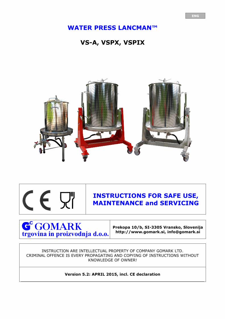
WATER PRESS LANCMAN™
VS-A, VSPX, VSPIX
INSTRUCTIONS FOR SAFE USE,
MAINTENANCE and SERVICING
Prekopa 10/b, SI-3305 Vransko, Slovenija
http://www.gomark.si, [email protected]
INSTRUCTION ARE INTELLECTUAL PROPERTY OF COMPANY GOMARK LTD.
CRIMINAL OFFENCE IS EVERY PROPAGATING AND COPYING OF INSTRUCTIONS WITHOUT
KNOWLEDGE OF OWNER!
Version 5.2: APRIL 2015, incl. CE declaration

ENG
2
WARNING
THIS MACHINE CAN BE USED ONLY BY A PERSON WHO HAS BEEN
ACQUAINTED WITH THE INSTRUCTIONS FOR
USE AND SAFETY WARNINGS!
WHEN HANDING OVER THE PRODUCT TO A THIRD PARTY THE INSTRUCTIONS FOR SAFE
USE, MAINTENACE AND SERVICING MUST ALSO BE HANDED OVER!
ENG
3
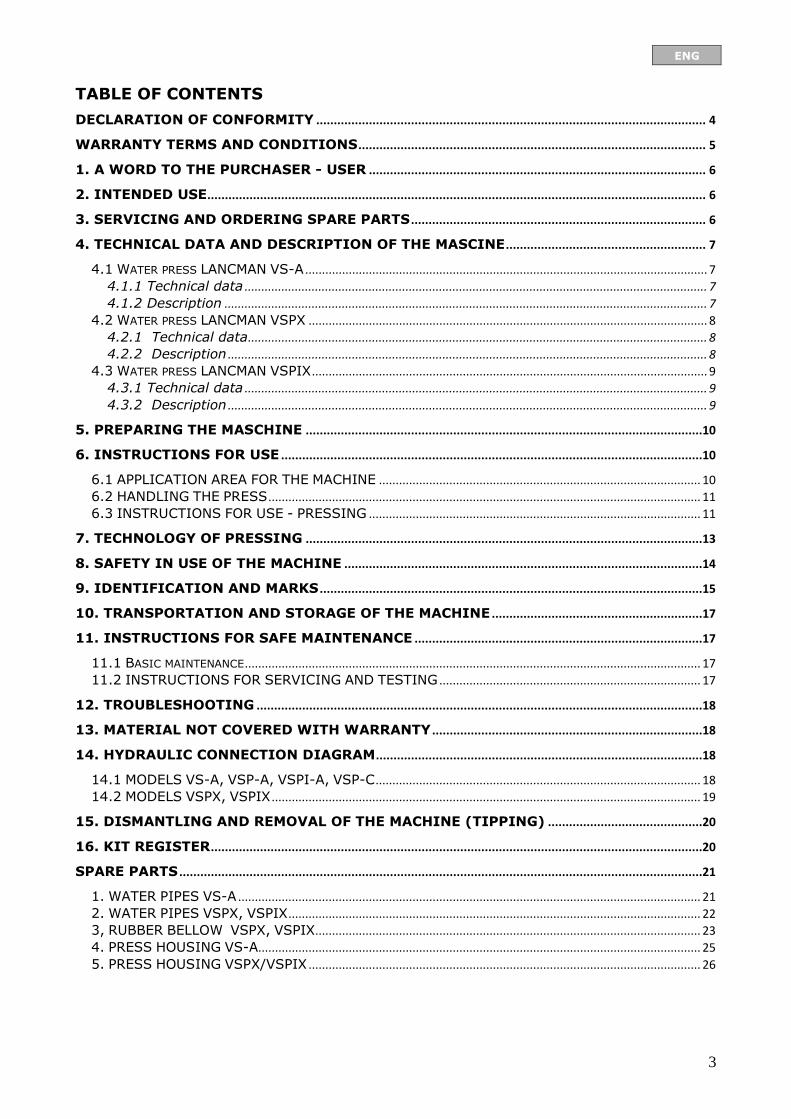
TABLE OF CONTENTS
DECLARATION OF CONFORMITY ............................................................................................................... 4
WARRANTY TERMS AND CONDITIONS ................................................................................................... 5
1. A WORD TO THE PURCHASER - USER ................................................................................................ 6
2. INTENDED USE.............................................................................................................................................. 6
3. SERVICING AND ORDERING SPARE PARTS .................................................................................... 6
4. TECHNICAL DATA AND DESCRIPTION OF THE MASCINE ......................................................... 7
4.1 WATER PRESS LANCMAN VS-A ........................................................................................................................ 7 4.1.1 Technical data .......................................................................................................................................... 7 4.1.2 Description ................................................................................................................................................ 7
4.2 WATER PRESS LANCMAN VSPX ....................................................................................................................... 8 4.2.1 Technical data ......................................................................................................................................... 8 4.2.2 Description ............................................................................................................................................... 8
4.3 WATER PRESS LANCMAN VSPIX ...................................................................................................................... 9 4.3.1 Technical data .......................................................................................................................................... 9 4.3.2 Description ............................................................................................................................................... 9
5. PREPARING THE MASCHINE .................................................................................................................10
6. INSTRUCTIONS FOR USE ........................................................................................................................10
6.1 APPLICATION AREA FOR THE MACHINE ................................................................................................ 10 6.2 HANDLING THE PRESS ................................................................................................................................. 11 6.3 INSTRUCTIONS FOR USE - PRESSING ................................................................................................... 11
7. TECHNOLOGY OF PRESSING .................................................................................................................13
8. SAFETY IN USE OF THE MACHINE ......................................................................................................14
9. IDENTIFICATION AND MARKS .............................................................................................................15
10. TRANSPORTATION AND STORAGE OF THE MACHINE ............................................................17
11. INSTRUCTIONS FOR SAFE MAINTENANCE ..................................................................................17
11.1 BASIC MAINTENANCE ........................................................................................................................................ 17 11.2 INSTRUCTIONS FOR SERVICING AND TESTING .............................................................................. 17
12. TROUBLESHOOTING ...............................................................................................................................18
13. MATERIAL NOT COVERED WITH WARRANTY .............................................................................18
14. HYDRAULIC CONNECTION DIAGRAM .............................................................................................18
14.1 MODELS VS-A, VSP-A, VSPI-A, VSP-C ................................................................................................. 18 14.2 MODELS VSPX, VSPIX ................................................................................................................................ 19
15. DISMANTLING AND REMOVAL OF THE MACHINE (TIPPING) ............................................20
16. KIT REGISTER ............................................................................................................................................20
SPARE PARTS .....................................................................................................................................................21
1. WATER PIPES VS-A .......................................................................................................................................... 21 2. WATER PIPES VSPX, VSPIX ........................................................................................................................... 22 3, RUBBER BELLOW VSPX, VSPIX................................................................................................................... 23 4. PRESS HOUSING VS-A.................................................................................................................................... 25 5. PRESS HOUSING VSPX/VSPIX ..................................................................................................................... 26
ENG
4
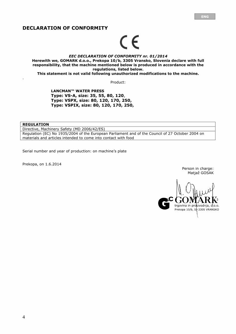
DECLARATION OF CONFORMITY
EEC DECLARATION OF CONFORMITY nr. 01/2014
Herewith we, GOMARK d.o.o., Prekopa 10/b, 3305 Vransko, Slovenia declare with full responsibility, that the machine mentioned below is produced in accordance with the
regulations, listed below. This statement is not valid following unauthorized modifications to the machine.
. Product:
LANCMAN™ WATER PRESS
Type: VS-A, size: 35, 55, 80, 120,
Type: VSPX, size: 80, 120, 170, 250,
Type: VSPIX, size: 80, 120, 170, 250,
REGULATION
Directive, Machinery Safety (MD 2006/42/ES)
Regulation (EC) No 1935/2004 of the European Parliament and of the Council of 27 October 2004 on materials and articles intended to come into contact with food
Serial number and year of production: on machine’s plate
Prekopa, on 1.6.2014
Person in charge: Matjaž GOSAK
ENG
5
WARRANTY TERMS AND CONDITIONS The warranty applies to machines and components - if used properly (as described in the user manual)
they will work flawlessly. Warranty period:
- for home use: 24 months, - for professional use: 12 months (industry).
The warranty covers replacement of defective parts and repair work, but excludes transport fees.
Warranty applies only with a correctly completed warranty certificate and receipt of purchase. The warranty is voided if: - failure to comply with the user’s manual, - if it is found that a pre-repair was carried out by an unauthorized person,
- if non-original spare parts were built in,
- if the product was used in an negligent manner, - due to failures, made by mechanical blows caused by the buyer or a third person. The warranty does not apply for expendable materials, stated in the instructions. The warranty does not apply in the case of failure to comply with the user's manual which is an integral part of the machine. Warranty also does not apply in case of unauthorized repairs to the machine and
changes of the machine. Warranty repairs are carried out by the authorized service stated by your dealer or dealer who sold you the machine.
ENG
6
1. A WORD TO THE PURCHASER - USER
We thank you for the trust you have shown us by buying our product. We are convinced that
you will be pleased with it.
Before first use one must thoroughly read and comprehend the instructions for safe use and
maintenance, where one will discover the intended function, functionality and machine’s work
environment. The instructions are written in a way so that one is acquainted with all the
required activities even before the machine’s first use, maintenance and regular servicing.
In case the product would be handed over to a third party, the instructions for
safe use, maintenance and servicing must also be handed over.
When reading the instructions, one must pay extra attention to the chapters and paragraphs
that are labeled with this mark.
Beside the text in the instructions this mark especially emphasizes the
importance of records in a definite chapter of the instructions.
Every partial or complete reproduction of these instructions, text and pictures is a
criminal offence.
2. INTENDED USE
The water press is intended for extracting juice by pressing different kinds of crushed fruit with water pressure derived from the water supply system. Any use other than that described is
considered ineligible and the manufacturer does not guarantee safety and functionality. Any remodelling and replacement of the original components of the press eliminates the warranty of the manufacturer for safety and functionality of the machine. Operating temperature range: 5° C to 50° C (41 to 122 degree Fahrenheit).
3. SERVICING AND ORDERING SPARE PARTS
Servicing and troubleshooting during the warranty period and afterwards will be performed by:
Gomark, trade and production Ltd.
Prekopa 10/b, SI-3305 Vransko
Telephone: 03/700 15 03
When ordering spare parts one must always give the following information:
- name of machine
- type of machine
- serial number of machine
- year of production of machine
All the data required for ordering spare parts is written on the plate or on the permanent label
that is placed on the machine.

ENG
7
4. TECHNICAL DATA AND DESCRIPTION OF THE MASCINE
4.1 Water press LANCMAN VS-A
4.1.1 Technical data Description WATER PRESS LANCMAN
Type: VS-A 35 VS-A 55 VS-A 80 VS-A 120
Dimensions (mm):
(inch)
550x550x950
22x22x37
600x600x950
24x24x37
600x600x1250
24x24x49
650x650x1250
26x26x49
Basket size: l/gal 35l/9,25 gal 55l/14,5 gal 80l/21,1 gal 120l/31,7 gal
Bowl material: X5CrNi1810 (stainless steel) – W.Nr. 1.4301
Cover material: X5CrNi1810 (stainless steel) – W.Nr. 1.4301
Basket material: X5CrNi1810 (stainless steel) – W.Nr. 1.4301
Fixed nut material: stainless steel
Utilizations pressure
bar/psi:
3,8 bar 55 psi
2,8 bar 41 psi
Highest allowed
pressure bar/psi:
4,0bar/58 psi safety valve
3,0 bar/43,5 psi – safety valve
Charging: bar/psi Water supply network 3 bar/43,5 psi
Total weight kg/lb: 30kg/66 lb 35kg/77 lb 40kg/88 lb 55kg/121 lb
Production date: SEE THE DECLARATION
4.1.2 Description
1. VENTING TAP
2. FIXING NUT
3. COVER
4. BASKET
5. BOWL
6. BOWL OUTLET
7. *WHEELS
8. OUTLET PIPE
9. SAFETY VALVE
10.PRESSURE GAUGE
11.*PRESSURE REGULATOR
12.INLET PIPE
* NOT ON MODEL VS-35
ENG
8
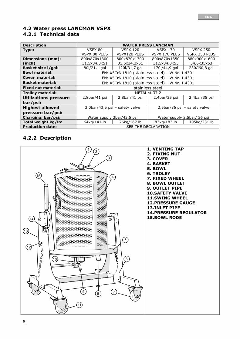
4.2 Water press LANCMAN VSPX 4.2.1 Technical data Description WATER PRESS LANCMAN
Type: VSPX 80 VSPX 80 PLUS
VSPX 120 VSPX120 PLUS
VSPX 170 VSPX 170 PLUS
VSPX 250 VSPX 250 PLUS
Dimensions (mm): (inch)
800x870x1300 31,5x34,3x51
800x870x1300 31,5x34,3x51
800x870x1350 31,5x34,3x53
880x900x1600 34,6x35x63
Basket size l/gal: 80l/21,1 gal 120l/31,7 gal 170l/44,9 gal 230/l60,8 gal
Bowl material: EN: X5CrNi1810 (stainless steel) – W.Nr. 1.4301
Cover material: EN: X5CrNi1810 (stainless steel) – W.Nr. 1.4301
Basket material: EN: X5CrNi1810 (stainless steel) – W.Nr. 1.4301
Fixed nut material: stainless steel Trolley material: METAL st.37.2
Utilizations pressure
bar/psi:
2,8bar/41 psi 2,8bar/41 psi 2,4bar/35 psi 2,4bar/35 psi
Highest allowed
pressure bar/psi:
3,0bar/43,5 psi – safety valve 2,5bar/36 psi – safety valve
Charging: bar/psi: Water supply 3bar/43,5 psi Water supply 2,5bar/ 36 psi
Total weight kg/lb: 64kg/141 lb 76kg/167 lb 83kg/183 lb 105kg/231 lb
Production date: SEE THE DECLARATION
4.2.2 Description
1. VENTING TAP
2. FIXING NUT
3. COVER
4. BASKET
5. BOWL
6. TROLEY
7. FIXED WHEEL
8. BOWL OUTLET
9. OUTLET PIPE
10.SAFETY VALVE
11.SWING WHEEL
12.PRESSURE GAUGE
13.INLET PIPE
14.PRESSURE REGULATOR
15.BOWL RODE
ENG
9
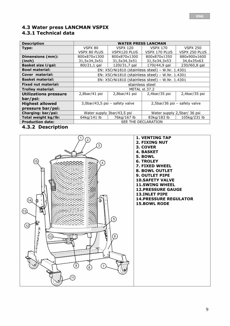
4.3 Water press LANCMAN VSPIX 4.3.1 Technical data Description WATER PRESS LANCMAN
Type: VSPX 80 VSPX 80 PLUS
VSPX 120 VSPX120 PLUS
VSPX 170 VSPX 170 PLUS
VSPX 250 VSPX 250 PLUS
Dimensions (mm): (inch)
800x870x1300 31,5x34,3x51
800x870x1300 31,5x34,3x51
800x870x1350 31,5x34,3x53
880x900x1600 34,6x35x63
Basket size l/gal: 80l/21,1 gal 120l/31,7 gal 170l/44,9 gal 230/l60,8 gal
Bowl material: EN: X5CrNi1810 (stainless steel) – W.Nr. 1.4301
Cover material: EN: X5CrNi1810 (stainless steel) – W.Nr. 1.4301
Basket material: EN: X5CrNi1810 (stainless steel) – W.Nr. 1.4301
Fixed nut material: stainless steel Trolley material: METAL st.37.2
Utilizations pressure
bar/psi:
2,8bar/41 psi 2,8bar/41 psi 2,4bar/35 psi 2,4bar/35 psi
Highest allowed
pressure bar/psi:
3,0bar/43,5 psi – safety valve 2,5bar/36 psi – safety valve
Charging: bar/psi: Water supply 3bar/43,5 psi Water supply 2,5bar/ 36 psi
Total weight kg/lb: 64kg/141 lb 76kg/167 lb 83kg/183 lb 105kg/231 lb
Production date: SEE THE DECLARATION
4.3.2 Description
1. VENTING TAP
2. FIXING NUT
3. COVER
4. BASKET
5. BOWL
6. TROLEY
7. FIXED WHEEL
8. BOWL OUTLET
9. OUTLET PIPE
10.SAFETY VALVE
11.SWING WHEEL
12.PRESSURE GAUGE
13.INLET PIPE
14.PRESSURE REGULATOR
15.BOWL RODE
ENG
10
5. PREPARING THE MASCHINE
The press is powered with energy derived from water pressure, and presses previously crushed
fruit towards the wall of the press basket. An efficient pressing requires a pressure of 2,5 bar
(36 psi) which is achieved when the press is connected to the water supply system. The
membrane is mounted axially in the middle of the pressure zone and is attached to the bottom
of the container with a flange and six screws.
Cleaning the press:
Before using the press for the first time and at the beginning of every season,
clean the press with water!
6. INSTRUCTIONS FOR USE
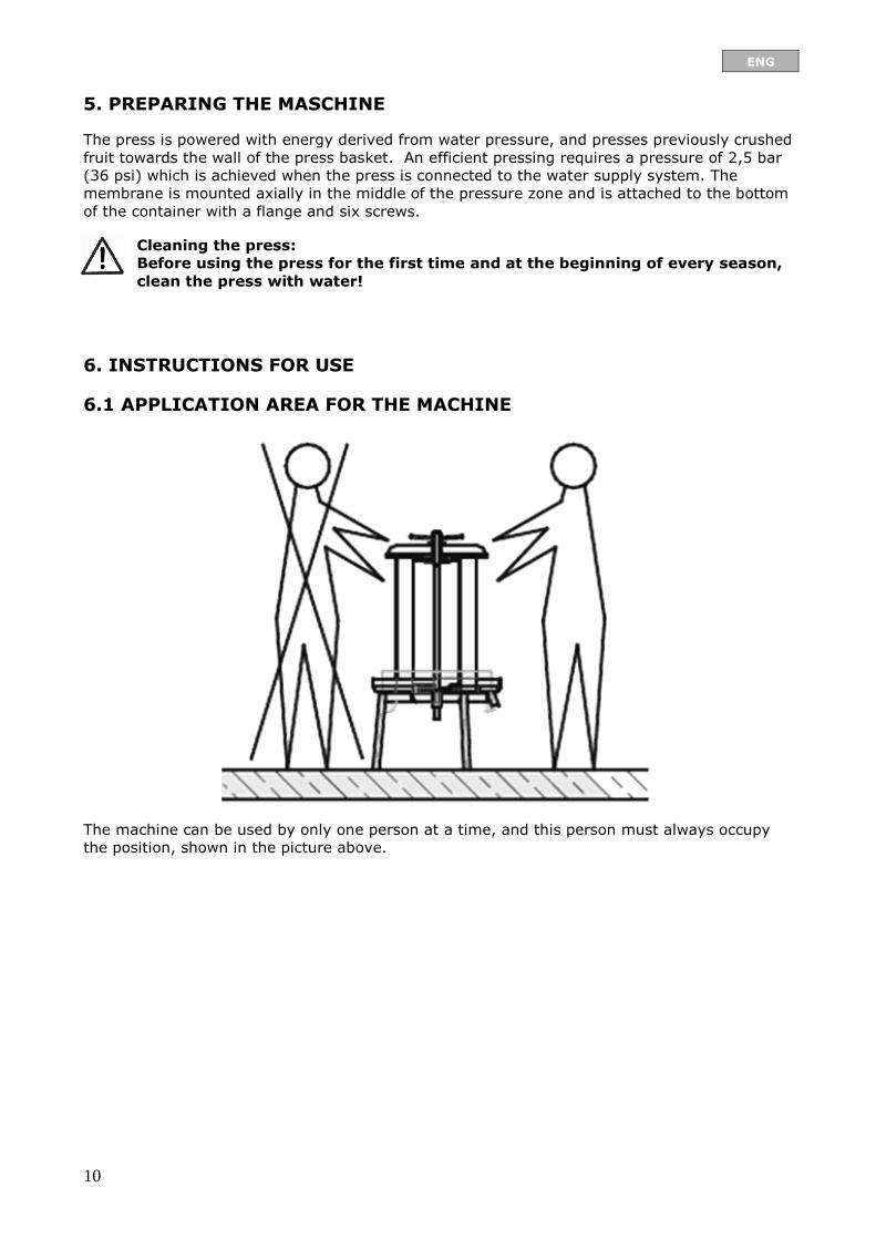
6.1 APPLICATION AREA FOR THE MACHINE
The machine can be used by only one person at a time, and this person must always occupy
the position, shown in the picture above.
ENG
11
6.2 HANDLING THE PRESS
1. PREPARE THE PRESS FOR OPERATION,
2. FILL THE BASKET OF THE PRESS WITH A CRUSHED PRODUCT (APPLES, GRAPES …), 3. PLACE THE LID ON THE BASKET AND SCREW IT DOWN WITH THE NUT, 4. ATTACH THE PRESS TO THE WATER SUPPLY SYSTEM USING A GARDEN HOSE, 5. OPEN THE SUPPLY VALVE; THE PRESS BEGINS TO OPERATE, 6. … SUPERVISE THE PRESS OPERATION …, 7. WHEN FINISHED, OPEN THE WASTE VALVE SO THAT ALL WATER POURS OUT OF THE
PRESS,
8. REMOVE THE NUT HOLDING THE LID AND THE LID ITSELF 9. CLEAN THE PRESS WITH WATER.
6.3 INSTRUCTIONS FOR USE - PRESSING
Fruit presses utilizing water pressure are the most modern type for pressing grapes, fruit, juice containing peels etc., lees, currants, blueberries, red beet and all kinds of fresh or boiled vegetables and fruits from which juice can be extracted. Each kind of fruit or vegetable requires a different pressing
method. The volume of a water press is 55 to 250 l (14.5 to 66 US gallons). The water press is made up of three complexes: base, pressing chamber and water supply system. The base can be fixed or mobile – tilting. The fixed base (VS-A) has three fixed legs on wheels for an easier transfer of the press. The mobile (VSP-A, VSP-C, VSPX) - tilting undercarriage is made up of a trolley with two or four wheels.
If there are four wheels, two come with brakes and two are swivel wheels enabling easier transport in the basement, wine cellar and in the yard. The composition also includes a tilting system to facilitate emptying the pressed-out material. The base comes in painted or stainless steel variety. The pressing chamber is composed of a lid with a fitting nut, a perforated basket and a container with
an outlet. The container and the water supply system are fixed to the base of the press. The container is especially braced and so is the lid which is attached with a fixing nut to the basket itself, to withstand the
strong pressure generated during pressing. The construction is such that the draining basket is well placed. All materials are made of high quality stainless steel, electrically polished before installation that is suitable for use in food production. The water supply system creates pressure in the basket, enabling the operation of the pressing chamber. The water inlet is regulated and fed into a vertical column with a vent valve at the top and high quality bellows made of rubber which expands as the water starts flowing into the bellows. The pressing procedure is as follows: Before charging the chamber, wash the entire press using warm
water and detergent (the use of detergent is optional). However do not use detergent or water pressure when washing the bellows. The rubber can be washed only with warm or cold water.
When charging the chamber do not compress the crushed fruit, since the result is going to be worse. When charging, the toggle valve of the collecting container should be open. If it is not the capacity of the press may be smaller. It is necessary to enable venting of the
press. Always fill the press to the top (the outermost edge of the peripheral plate).
Always press only when it is filled up to the upper edge. Failure to do so may cause damage, to the bellows, which is not covered by the
warranty.
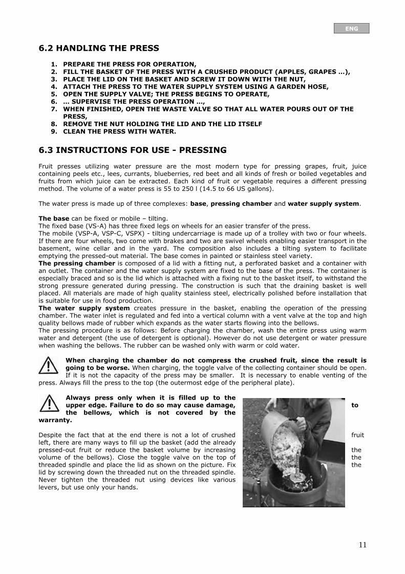
Despite the fact that at the end there is not a lot of crushed fruit left, there are many ways to fill up the basket (add the already pressed-out fruit or reduce the basket volume by increasing the volume of the bellows). Close the toggle valve on the top of the threaded spindle and place the lid as shown on the picture. Fix the lid by screwing down the threaded nut on the threaded spindle. Never tighten the threaded nut using devices like various
levers, but use only your hands.

ENG
12
Connect a flexible hose to the water
supply valve (picture). Connect the other end of the hose to the water supply system. Open the ball valve for water supply and the valve on the water supply network and then start pressing.
The membrane of the press fills with water for some time. When you notice water leaking off the vent valve, you should close it completely. The system will increase pressure which can be read of the manometer. If the pressure
rises over 2,5 or 3 bar (36 or 43,5 psi), the safety valve will open and some water will flow out of the system. By closing and opening the valve for water
supply you can avoid the water from flowing out of the system through the safety valve, provided you constantly
monitor the pressure level on the manometer. The press can be disencumbered by closing the valve for water supply and opening the toggle ball valve and vent valve on the threaded spindle. When the pressure drops to 0,0 bar (0.0 psi), unscrew the
threaded nut and remove the lid. First, loosen the pressed fruit and then lift the peripheral plate from the collecting container and clean it. If an additional grid was used for pressing, removal is easier if you remove the grid first. When finished thoroughly clean the press. The press should be always cleaned only with clean water. Stainless steel
material can be cleaned with household detergents, but expansion bellows are cleaned only with water.
MODEL VSPX, VSPIX Use your left hand to pull up the ball on the plug handle; meanwhile use your right hand to pull the lid handle towards you and move the press in the prone position. Make sure that the plug hooks into the last slot. Then unscrew the lock nut, remove the lid and empty the press basket using the grid which was placed in the press before the starting the process.
ENG
13
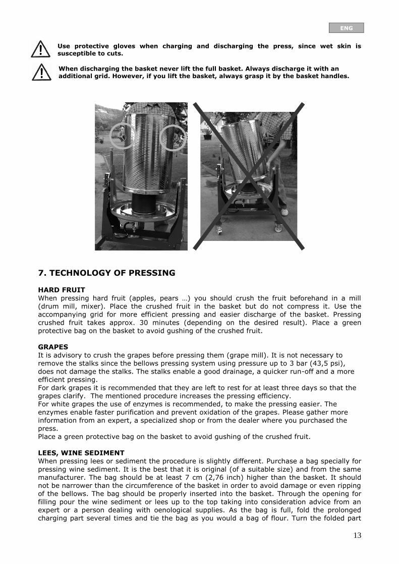
Use protective gloves when charging and discharging the press, since wet skin is
susceptible to cuts.
When discharging the basket never lift the full basket. Always discharge it with an additional grid. However, if you lift the basket, always grasp it by the basket handles.
7. TECHNOLOGY OF PRESSING
HARD FRUIT
When pressing hard fruit (apples, pears …) you should crush the fruit beforehand in a mill
(drum mill, mixer). Place the crushed fruit in the basket but do not compress it. Use the
accompanying grid for more efficient pressing and easier discharge of the basket. Pressing
crushed fruit takes approx. 30 minutes (depending on the desired result). Place a green
protective bag on the basket to avoid gushing of the crushed fruit.
GRAPES
It is advisory to crush the grapes before pressing them (grape mill). It is not necessary to
remove the stalks since the bellows pressing system using pressure up to 3 bar (43,5 psi),
does not damage the stalks. The stalks enable a good drainage, a quicker run-off and a more
efficient pressing.
For dark grapes it is recommended that they are left to rest for at least three days so that the
grapes clarify. The mentioned procedure increases the pressing efficiency.
For white grapes the use of enzymes is recommended, to make the pressing easier. The
enzymes enable faster purification and prevent oxidation of the grapes. Please gather more
information from an expert, a specialized shop or from the dealer where you purchased the
press.
Place a green protective bag on the basket to avoid gushing of the crushed fruit.
LEES, WINE SEDIMENT
When pressing lees or sediment the procedure is slightly different. Purchase a bag specially for
pressing wine sediment. It is the best that it is original (of a suitable size) and from the same
manufacturer. The bag should be at least 7 cm (2,76 inch) higher than the basket. It should
not be narrower than the circumference of the basket in order to avoid damage or even ripping
of the bellows. The bag should be properly inserted into the basket. Through the opening for
filling pour the wine sediment or lees up to the top taking into consideration advice from an
expert or a person dealing with oenological supplies. As the bag is full, fold the prolonged
charging part several times and tie the bag as you would a bag of flour. Turn the folded part
ENG
14
towards the basket and not against the bellows. Slightly open the water supply valve since the
pressure in the chamber should not exceed 1 bar (14,5 psi). The pressing takes 6 to 10
hours, depending on the size of the press.
When pressing the wine sediment and lees use original bags of the appropriate
size in order to avoid damage to the bellows. Pressing the lees and the wine
sediment using pressure higher than 1 bar (14,5 psi) can damage the bellows.
This is regarded as mechanical damage and is therefore not covered by warranty!
If the pressure during pressing is higher than 1 bar (14,5 psi) the pressing time will
not be shorter.
8. SAFETY IN USE OF THE MACHINE
– The machine can be used only by professionally trained and healthy persons older than 18
years.
– While operating the machine must not be moved or displaced.
– While operating the machine must not be cleaned or repaired.
– For the user's safety the machine must not be charged with air.
– However, it is necessary to give an assurance that the outlet connector of the
safety valve is unhindered!
– Never press without the lid!
Before first use of the machine one must:
– carefully read and comprehend the contents of these instructions,
– look for all warnings, symbols and inscriptions on the machine, and discover their meaning
in these instructions, Chapter VII,
– read the instructions and get to know all parts of the machine and their functions, Chapter
IV,
– pay attention to the instructions before every use of the machine.
Before every use of the machine one must:
– pay attention to the instructions before first use of the machine.
– check the machine before every use; the description of the procedure can be found in
Chapter VI,
– check that all parts of the machine are in prime condition,
– put the machine on firm, level ground that is not slippery and allow at least 2m2 (21,53 ft2)
surface for use,
– pay attention the to machine's biggest incline which must not be bigger than 1 degree of
arc, and the lined element must not be taller than 10mm (0,04 inch),
– make sure that the illumination of the machine and work space is sufficient (at least 150
Lux),
– people who work with the machine must wear tight clothes, protect long hair and wear no
jeweler, ties or similar items,
– make sure that working with the machine threatens nobody in the vicinity and that there are
no children nearby,
– make sure that work space surroundings are tidy and not cluttered with other items,

ENG
15
9. IDENTIFICATION AND MARKS
The machine is made in accordance with standards that allow the manufacturer to label it with
CE. However, the machine causes some perils, and therefore there are, in accordance with
preserving machine’s functionality, warning inscriptions and symbols – pictographs - on it.
Explanation of the warning symbols (pictographs) on the machine:
- read instr. manual
before use - don't use air for
pressing - use glasses while
pressing
- pressure regulation +/-

ENG
16
1. TRADEMARK – STICKER, 2. PRODUCER TABLE,
o NAME, o TYPE, o MAX PRESSURE, o WORK MEDIA, o WEIGHT,
o PROD. YEAR, o PRODUCER, o VARNINGS, o EAN13,
3. TRADE MARK, 4. VARNINGS
ENG
17
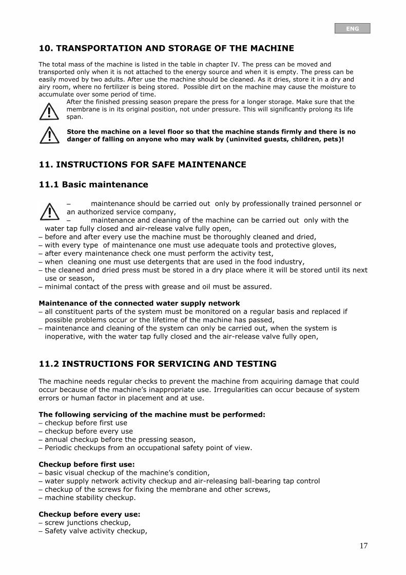
10. TRANSPORTATION AND STORAGE OF THE MACHINE The total mass of the machine is listed in the table in chapter IV. The press can be moved and
transported only when it is not attached to the energy source and when it is empty. The press can be easily moved by two adults. After use the machine should be cleaned. As it dries, store it in a dry and airy room, where no fertilizer is being stored. Possible dirt on the machine may cause the moisture to accumulate over some period of time.
After the finished pressing season prepare the press for a longer storage. Make sure that the membrane is in its original position, not under pressure. This will significantly prolong its life span.
Store the machine on a level floor so that the machine stands firmly and there is no danger of falling on anyone who may walk by (uninvited guests, children, pets)!
11. INSTRUCTIONS FOR SAFE MAINTENANCE
11.1 Basic maintenance
– maintenance should be carried out only by professionally trained personnel or
an authorized service company,
– maintenance and cleaning of the machine can be carried out only with the
water tap fully closed and air-release valve fully open,
– before and after every use the machine must be thoroughly cleaned and dried,
– with every type of maintenance one must use adequate tools and protective gloves,
– after every maintenance check one must perform the activity test,
– when cleaning one must use detergents that are used in the food industry,
– the cleaned and dried press must be stored in a dry place where it will be stored until its next
use or season,
– minimal contact of the press with grease and oil must be assured.
Maintenance of the connected water supply network
– all constituent parts of the system must be monitored on a regular basis and replaced if
possible problems occur or the lifetime of the machine has passed,
– maintenance and cleaning of the system can only be carried out, when the system is
inoperative, with the water tap fully closed and the air-release valve fully open,
11.2 INSTRUCTIONS FOR SERVICING AND TESTING
The machine needs regular checks to prevent the machine from acquiring damage that could
occur because of the machine’s inappropriate use. Irregularities can occur because of system
errors or human factor in placement and at use.
The following servicing of the machine must be performed:
– checkup before first use
– checkup before every use
– annual checkup before the pressing season,
– Periodic checkups from an occupational safety point of view.
Checkup before first use:
– basic visual checkup of the machine’s condition,
– water supply network activity checkup and air-releasing ball-bearing tap control
– checkup of the screws for fixing the membrane and other screws,
– machine stability checkup.
Checkup before every use:
– screw junctions checkup,
– Safety valve activity checkup,
ENG
18
– visual superficial checkup of the membrane.
Annual checkup before the pressing season:
– checkup of the peripheral metal sheet and welded spots in the framework,
– complete contents of service before every use.
12. TROUBLESHOOTING Trouble Cause Solution
Pressure membrane doesn't
stretch
Air-release valve isn’t closed. Tighten up the air-release valve.
Outlet valve isn’t closed. Tighten up the outlet valve
Air is in the water pressure application system.
Unwind the outlet valve until the water starts running
again.
If you still haven't fixed the problem, call the authorized service company.
13. MATERIAL NOT COVERED WITH WARRANTY
Material, not covered with warranty:
– additional pressing net,
– additional protection bag.
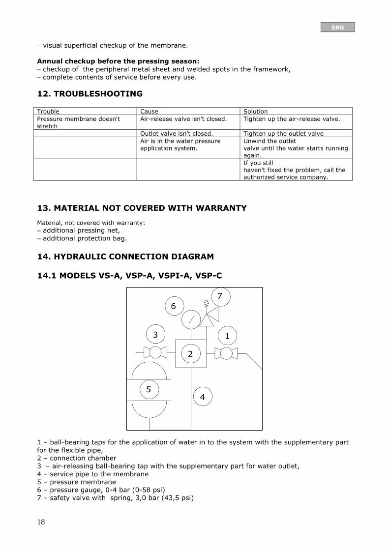
14. HYDRAULIC CONNECTION DIAGRAM
14.1 MODELS VS-A, VSP-A, VSPI-A, VSP-C
1 – ball-bearing taps for the application of water in to the system with the supplementary part
for the flexible pipe,
2 – connection chamber
3 – air-releasing ball-bearing tap with the supplementary part for water outlet,
4 – service pipe to the membrane
5 – pressure membrane
6 – pressure gauge, 0-4 bar (0-58 psi)
7 – safety valve with spring, 3,0 bar (43,5 psi)

ENG
19
14.2 MODELS VSPX, VSPIX
1 – ball-bearing taps for the application of water in to the system with the supplementary part
for the flexible pipe,
2 – connection chamber
3 – air-releasing ball-bearing tap with the supplementary part for water outlet,
4 – service pipe to the membrane
5 – pressure membrane
6 – pressure gauge, 0-4bar (0-58 psi)
7 – safety valve with spring, 3,0 bar (43,5 psi)
8 – pressure regulator
ENG
20
15. DISMANTLING AND REMOVAL OF THE MACHINE (TIPPING)
With regard to the instructions for safe use, maintenance and servicing, the machine as a
whole has a fixed lifetime limit of 8 years. There are different lifetime limits for separate
components of the machine, so they must be regularly replaced with new ones in case of
certain problems, wear and tear and mechanical damage. Replacement can be performed only
by purchasing technically adequate or original spare parts.
After the lifetime of the machine expires:
After the lifetime expires, the whole machine has to be disposed of at a collection point that is
earmarked especially for such machines, and in accordance with waste classification.
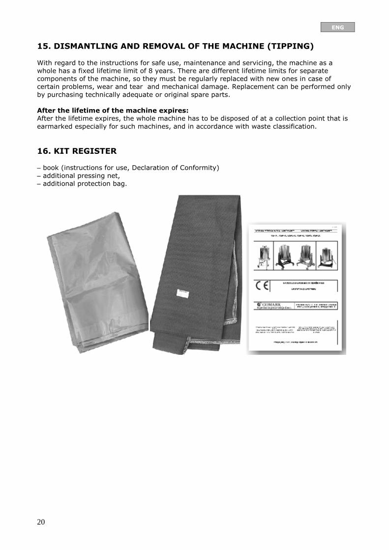
16. KIT REGISTER
– book (instructions for use, Declaration of Conformity)
– additional pressing net,
– additional protection bag.
SPARE PARTS
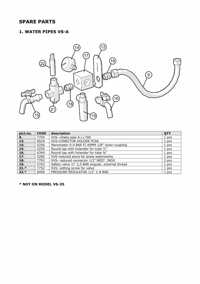
1. WATER PIPES VS-A
pict.no. CODE description QTY
9. 7754 XVS- intake pipe A L=700 1 pcs
13. 8929 XVS-CONECTOR HOLDER PCSA 1 pcs
14. 5256 Manometer 0-4 BAR FI 40MM 1/8'' lower coupling 1 pcs
15. 5255 Round tap with holander for tube ½'' 1 pcs
16. 6349 Round tap with holander for tube ¾'' 1 pcs
17. 5280 XVS-reduced piece for press waterworks 1 pcs
18. 7792 XVS- reduced connector 1/2" NEST. INOX 2 pcs
19. 5763 Safety valve ½'' 2,5 BAR angular, external thread 1 pcs
21.* 7752 XVS- setting screw for valve 1 pcs
22.* 6459 PRESSURE REGULATOR 1/2" 1-8 BAR 1 pcs
* NOT ON MODEL VS-35
ENG
22
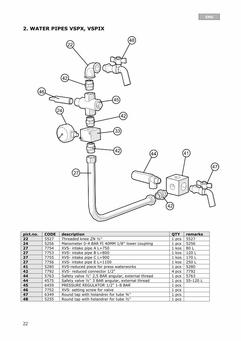
2. WATER PIPES VSPX, VSPIX
pict.no. CODE description QTY remarks
22 5527 Threaded knee ZN ½'' 1 pcs 5527
24 5256 Manometer 0-4 BAR FI 40MM 1/8'' lower coupling 1 pcs 5256
27 7754 XVS- intake pipe A L=750 1 kos 80 L
27 7753 XVS- intake pipe B L=800 1 kos 120 L
27 7755 XVS- intake pipe C L=900 1 kos 170 L
27 7756 XVS- intake pipe E L=1100 1 kos 250 L
41 5280 XVS-reduced piece for press waterworks 1 pcs 5280
42 7792 XVS- reduced connector 1/2" 4 pcs 7792
44 5763 Safety valve ½'' 2,5 BAR angular, external thread 1 pcs 5763
44 4575 Safety valve ½'' 3 BAR angular, external thread 1 pcs 55-120 L
45 6459 PRESSURE REGULATOR 1/2" 1-8 BAR 1 pcs
46 7752 XVS- setting screw for valve 1 pcs
47 6349 Round tap with holandrer for tube ¾'' 1 pcs
48 5255 Round tap with holandrer for tube ½'' 1 pcs

ENG
23
3. RUBBER BELLOW VSPX, VSPIX

ENG
24
pict.no. CODE description QTY remarks
1. 6426 RUBBER BELLOW LANCMAN 55 1 pcs 55 L
1. 6259 RUBBER BELLOW LANCMAN 60-80 1 pcs 80 L
1. 5335 RUBBER BELLOW LANCMAN 120-170 A SD27 1 pcs 120, 170 L
1. 5922 RUBBER BELLOW LANCMAN 250-300 1 pcs 250 L
2. 5281 XVS-FLANGE 115/85/6 (VS55 / VS80) 1 pcs 55, 80 L
2. 5547 XVS-FLANGE 240/190/6 (VS120/VS170) 1 pcs 120, 170, 250 L
3. 6388 XVS-FLANGE 55, 80 ASD 27 90/21×5 BOTTOM&UPPER 2 pcs 55 L
3. 6473 XVS-FLANGE 55 ASD 27 90/21×5 LOWER 2 pcs 80 L
3. 5548 XVS-FLANGE B,C,D SD 27 LOWER 130/30X6 2 pcs 120, 170 L
4. 7119 SCREW IMBUS INOX M6X25 DIN 7991 0,05 C 55, 80 L
4. 5733 SCREW IMBUS INOX M10X35 DIN 7991 0,06 C 120, 170, 250 L
5. 7120 NUT INOX M6 DIN 934 0,05 C 55, 80 L
5. 5306 NUT INOX M10 0,06 C 120, 170, 250 L
6. 6770 DOWEL 6×6×25 FORM A DIN 6885 CK45K 0,01 C
7. 6469 XVS-NUT SMALL LOWER G 1/2" 1 pcs 55, 80 L
7. 5516 XVS-NUT M30 LOWER - 40MM 1 pcs 120, 170, 250 l
8. 6351 NUT INOX M20 X 2,5 DIN 934 1 pcs 55, 80 L
8. 5517 XVS-NUT M30 UPPER INOX - 15 MM 1 pcs 120, 170, 250 L
10. 6224 XVS- AXE N.S.A. SD 3 V.S. 55 1 pcs 55 L
10. 5849 XVS- AXIS N.S.A. SD 3 V.S. 80 1 pcs 80 L
10. 5698 XVS- AXIS N.S.B. SD 3 V.S. 120 1 pcs 120 L
10. 5508 XVS- AXIS N.S.C SD 3-1 V.S. 170 1 pcs 170 L
10. 5700 XVS- AXIS N.S.E SD 3 V.S. 250 1 kos 250 L
11. 6752 O-RING NBR70SHORE 20×3 1 pcs 55, 80 L
11. 6256 O-RING NBR 70SHORE 30 X 3 1 pcs 120, 170, 250
12. 5257 RADIATOR PIPE.1/4" 1 pcs
20. 6464 XVS-RING 35/20/5 WITHOUT MORTISE 1 pcs 55, 80 L
20. 7469 XVS-RING 45/30/3 WITHOUT MORTISE 1 pcs 120, 170, 250 L
36. 5514 XVS-NUT INOX TR 26×5 WITH HANDLE 1 pcs 120, 170, 250 L
36. 6262 XVS-NUT INOX M20×2.5 WITH HANDLE 1 pcs 55, 80 L
37. 6299 XVS-RUBBER SEAL FI20/35X5 1 pcs 55, 80 L
37. 5785 XVS-RUBBER SEAL FI30X45 X3 1 pcs 120, 170, 250 L
38. 9418 XVS-MATICA ZATEZNA INOX TR26×5 FI55×45 1 kos 120, 170, 250 L
38. 6115 XVS-MATICA ZATEZNA INOX M20×2.5 Z ROČAJI 1 kos 55, 80 L

ENG
25
4. PRESS HOUSING VS-A
pict.no. CODE description QTY remarks
3. 5834 XVS-RUBBER SHOE DIAM. 30 3 pcs
4. 8396 NUT INOX M6 PLASTIC DIN 985 0,03 C 55, 80, 120 L
5. 8395 SCREW 6KT INOX M8×40 DIN 931 0,03 C 55, 80, 120 L
6. 5716 WHEEL POLIAMID FI 100/30/12/34/175 KG 2 pcs
7. 8034 XVS-BOWL FOOT SINGLE VS 2/2 1 pcs
8. 5906 WASHER INOX M12 0,02 C
9. 6353 DOWEL INOX 2.5×32 DIN 94 0,02 C
10. 6476 XVS-BASKET ZA VS 55 1 pcs 55 L
10. 5346 XVS-BASKET V.S. 80 1 pcs 80 L
10. 5605 XVS-BASKET V.S. 120 1 pcs 120 L
11. 8034 XVS-BOWL FOOT DOUBLE VS ½ 1 pcs
12. 5344 XVS-COVER V.S. 55, 80 1 pcs 55, 80 L
12. 5345 XVS-COVER V.S. 120 1 pcs 120 L
13. 5292 XVS-BOWL FOOT TYPE 55, 80 1 pcs 55, 80 L
13. 5343 XVS-BOWL FOOT TYPE 120 1 pcs 120 L
ENG
26
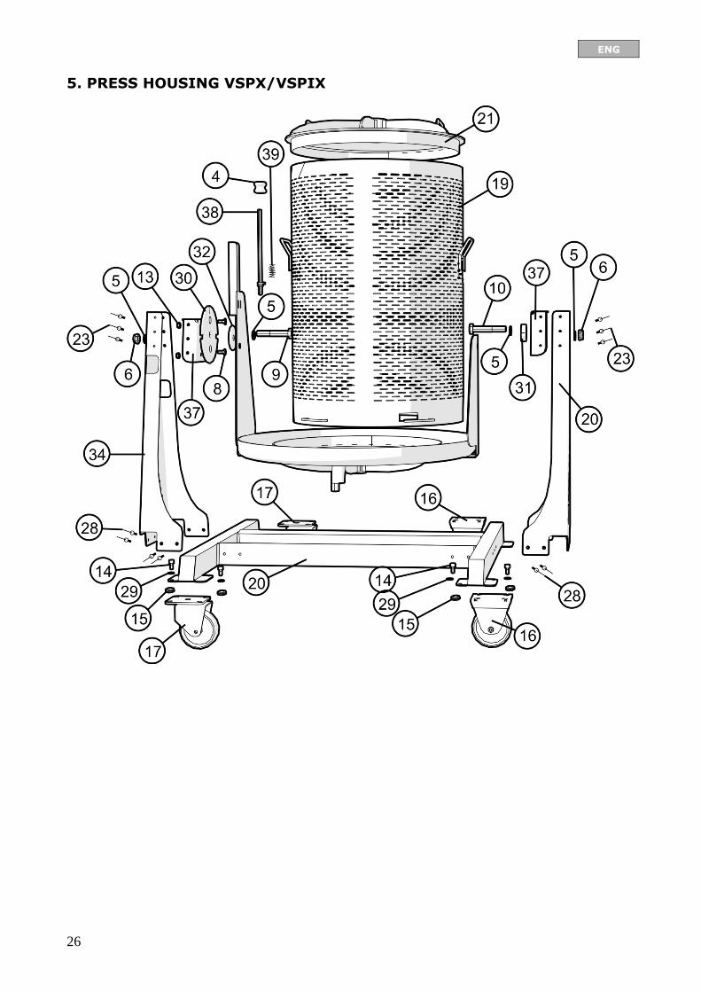
5. PRESS HOUSING VSPX/VSPIX
ENG
27
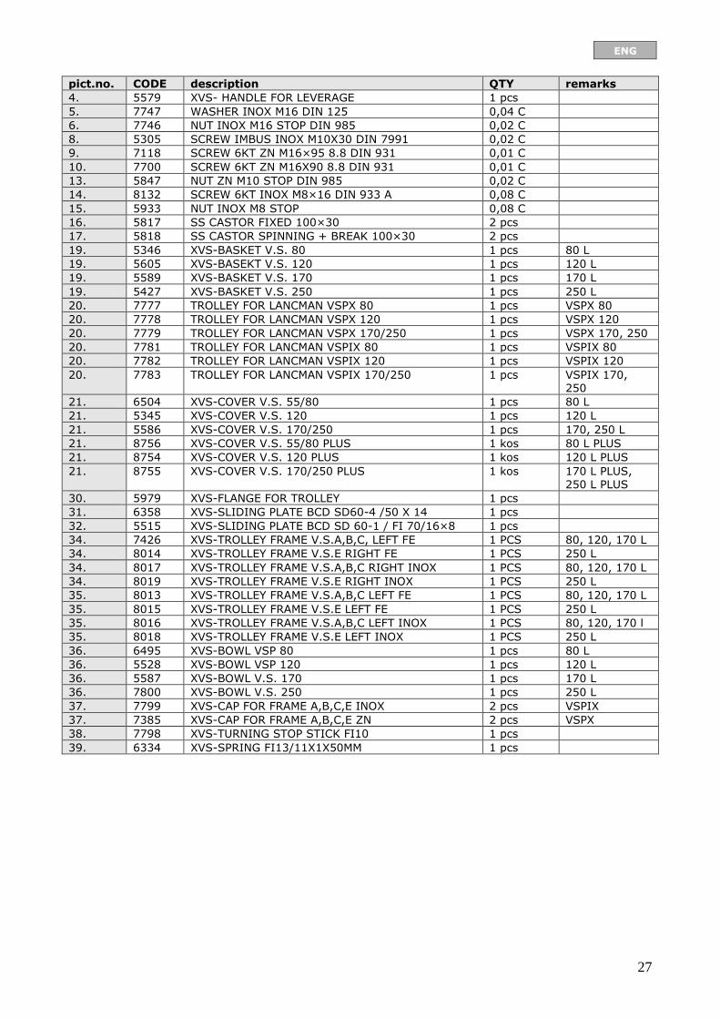
pict.no. CODE description QTY remarks
4. 5579 XVS- HANDLE FOR LEVERAGE 1 pcs
5. 7747 WASHER INOX M16 DIN 125 0,04 C
6. 7746 NUT INOX M16 STOP DIN 985 0,02 C
8. 5305 SCREW IMBUS INOX M10X30 DIN 7991 0,02 C
9. 7118 SCREW 6KT ZN M16×95 8.8 DIN 931 0,01 C
10. 7700 SCREW 6KT ZN M16X90 8.8 DIN 931 0,01 C
13. 5847 NUT ZN M10 STOP DIN 985 0,02 C
14. 8132 SCREW 6KT INOX M8×16 DIN 933 A 0,08 C
15. 5933 NUT INOX M8 STOP 0,08 C
16. 5817 SS CASTOR FIXED 100×30 2 pcs
17. 5818 SS CASTOR SPINNING + BREAK 100×30 2 pcs
19. 5346 XVS-BASKET V.S. 80 1 pcs 80 L
19. 5605 XVS-BASEKT V.S. 120 1 pcs 120 L
19. 5589 XVS-BASKET V.S. 170 1 pcs 170 L
19. 5427 XVS-BASKET V.S. 250 1 pcs 250 L
20. 7777 TROLLEY FOR LANCMAN VSPX 80 1 pcs VSPX 80
20. 7778 TROLLEY FOR LANCMAN VSPX 120 1 pcs VSPX 120
20. 7779 TROLLEY FOR LANCMAN VSPX 170/250 1 pcs VSPX 170, 250
20. 7781 TROLLEY FOR LANCMAN VSPIX 80 1 pcs VSPIX 80
20. 7782 TROLLEY FOR LANCMAN VSPIX 120 1 pcs VSPIX 120
20. 7783 TROLLEY FOR LANCMAN VSPIX 170/250 1 pcs VSPIX 170, 250
21. 6504 XVS-COVER V.S. 55/80 1 pcs 80 L
21. 5345 XVS-COVER V.S. 120 1 pcs 120 L
21. 5586 XVS-COVER V.S. 170/250 1 pcs 170, 250 L
21. 8756 XVS-COVER V.S. 55/80 PLUS 1 kos 80 L PLUS
21. 8754 XVS-COVER V.S. 120 PLUS 1 kos 120 L PLUS
21. 8755 XVS-COVER V.S. 170/250 PLUS 1 kos 170 L PLUS,
250 L PLUS
30. 5979 XVS-FLANGE FOR TROLLEY 1 pcs
31. 6358 XVS-SLIDING PLATE BCD SD60-4 /50 X 14 1 pcs
32. 5515 XVS-SLIDING PLATE BCD SD 60-1 / FI 70/16×8 1 pcs
34. 7426 XVS-TROLLEY FRAME V.S.A,B,C, LEFT FE 1 PCS 80, 120, 170 L
34. 8014 XVS-TROLLEY FRAME V.S.E RIGHT FE 1 PCS 250 L
34. 8017 XVS-TROLLEY FRAME V.S.A,B,C RIGHT INOX 1 PCS 80, 120, 170 L
34. 8019 XVS-TROLLEY FRAME V.S.E RIGHT INOX 1 PCS 250 L
35. 8013 XVS-TROLLEY FRAME V.S.A,B,C LEFT FE 1 PCS 80, 120, 170 L
35. 8015 XVS-TROLLEY FRAME V.S.E LEFT FE 1 PCS 250 L
35. 8016 XVS-TROLLEY FRAME V.S.A,B,C LEFT INOX 1 PCS 80, 120, 170 l
35. 8018 XVS-TROLLEY FRAME V.S.E LEFT INOX 1 PCS 250 L
36. 6495 XVS-BOWL VSP 80 1 pcs 80 L
36. 5528 XVS-BOWL VSP 120 1 pcs 120 L
36. 5587 XVS-BOWL V.S. 170 1 pcs 170 L
36. 7800 XVS-BOWL V.S. 250 1 pcs 250 L
37. 7799 XVS-CAP FOR FRAME A,B,C,E INOX 2 pcs VSPIX
37. 7385 XVS-CAP FOR FRAME A,B,C,E ZN 2 pcs VSPX
38. 7798 XVS-TURNING STOP STICK FI10 1 pcs
39. 6334 XVS-SPRING FI13/11X1X50MM 1 pcs
ENG
28