Watco Group Guide · or advanced requirements in terms of ... water is referred to as range. ‐...
24
Watco Group Engineering Guide Engineering and design principles for WCN‐Wacon and AQUAFAN Cooling Towers
-
Upload
duongthien -
Category
Documents
-
view
213 -
download
0
Transcript of Watco Group Guide · or advanced requirements in terms of ... water is referred to as range. ‐...

Watco Group Engineering Guide Engineering and design principles for WCN‐Wacon and AQUAFAN Cooling Towers

WATCO GROUP PTE LTD COOLING TOWER ENGINEERING GUIDE INTRODUCTION
WATCOEngineeringGuide This WATCO Engineering Guide provides System Management requirements and an indicative selection reference including discussion of different air inlet heights. The component section covers engineering criteria for the structure with consideration to profiles, handrails/ladders/platform, fan cones and basins. Separate sections discuss fans, gear drives and drive shafts, plus electric motors and controls as well as sections on water distribution and nozzles, exchange media fill types and air inlet protection. The WATCO manual also discusses drift eliminators, vibration switches and the WATCO blow down control system. Essential considerations like performance testing and guarantee and site specific sound considerations are covered in detail.
Finally, you will find coverage of special case cooling towers that deal with hot water, turbidity and water contaminated with things like bacterial growth and how to handle salt water. Availability of specification templates is also listed. Visit our websites for additional white papers on specific subjects related to cooling towers, such as: • Commissioning of Cooling Towers • Cooling Tower thermal capability • Counter flow vs Cross flow
Cooling Towers • Mechanically assembled Cooling
tower fills • Prevention of Legionellosis

WATCO GROUP PTE LTD COOLING TOWER ENGINEERING GUIDE OVERVIEW
WACONEngineeringGuideonWCNandAQUAFANCounterFlowCoolingTowers
OVERVIEW
• Introduction • System Design and Management
o System design o Cooling Tower Cost o System Management
• Selection reference (indicative) o Modular counter flow systems WCN o Modular turbine powered counter flow systems AQUAFAN
• Components o Structure and fill o Mechanics o WACON Automatic Blow down Control System
• Sound • CTI testing for tailor‐made cooling towers • Warranty and performance guarantee • Manufacturing and logistics • Specification templates:
o WCN o AQF o Others
• Company Profile

WATCO GROUP PTE LTD COOLING TOWER ENGINEERING GUIDE SYSTEM DESIGN AND MANAGEMENT
SystemDesignConsiderationsandSystemManagementThis section presents an overview of the engineering steps needed for a cooling tower design including Water Quality Management, referring to handling biological build up, Evaporation Loss, Blow‐down and design parameters.
SystemDesignWatco always has an open mind for the specific design limitations that are dictated by the client, such as practical limitations in aspects footprint, height or advanced requirements in terms of energy use, noise standards or maintenance. Based on the limitations several alternatives may be explored where a basic choice for the operational principle of the cooling tower with a specific combination of the cooling tower components (as presented over the next paragraphs) will lead to a specific tailored designed installation that meets the specific limitations and delivers on the design criteria.
Calculationguidelines:‐ Range: Temperature difference
between the hot and cold system water is referred to as range.
‐ Approach: The difference between the specified cold water temperature and the wet bulb temperature is the approach.
‐ Thermal efficiency, where:
HWT = Hot Water Temperature
CWT = Cold Water Temperature
WBT = design Wet Bulb Temperature: (HWT‐/‐CWT)/(HWT‐/‐WBT) x 100% = range
‐ KAV/L: standard for the performance of the cooling tower’s infill and determined by the size and relative surface of the infill in relation to the water volume at specific approach temperatures and L/G rations.
‐ L/G: Ration between liquid and gas in the cooling tower operation. Is used (with KAV/L) to predict the cooling behaviour.
‐ Cooling tower size parameters: kWh: the heat that the CT is
dissipating can easily be expressed in kWh according to following formula:
RT RT‐CT
‐ The difference between Chiller Tons and Cooling Tower Tons.
When making such comparisons, it is important to do so only for similar design conditions. When applied under different conditions (approach temperature) there may be substantial differences in the load in tonnage that an installation may be able to handle.

WATCO GROUP PTE LTD COOLING TOWER ENGINEERING GUIDE SYSTEM DESIGN AND MANAGEMENT
Coolingtowercost:True cost to a cooling tower purchaser is what WATCO defines as the CostofOwnership comprised of: ‐ Purchase price of the cooling
tower ‐ Cost of installation ‐ Cost of electricity ‐ Accumulated cost of maintenance ‐ Cost of consumables (chemicals
etc) ‐ Consequential cost of
unscheduled down time ‐ Cost of removing installation at
the end of its life time
CostofElectricityEvaluated over the full range of load conditions that the cooling tower is expected to handle which includes pumps and the fan. In processes were the cold water temp below certain level are non‐rewarding or possibly harmful there are opportunities for substantial energy savings by optimal control of the process. Especially the Aquafan where pump and fan optimally co‐operate, offers the most flexible energy management possibilities.
ConsequentialcostofunscheduleddowntimeThe cost of unscheduled down time can and probably will run up substantially once kicking in. A blown out gear drive or electromotor may not be an everyday event, but if it does happen, it is not an easy thing to fix. Apart from the possible delay in availability of replacement parts, the repair itself may be difficult to execute, especially when hoisting equipment may be required to have the parts available at the cooling tower (high rise buildings). WATCO design parameters are based upon the Cost of Ownership philosophy which requires consideration of all the variables beyond first cost.

WATCO GROUP PTE LTD COOLING TOWER ENGINEERING GUIDE SYSTEM DESIGN AND MANAGEMENT
SystemManagementandMaintenance
WaterqualityConsistent cooling water treatment is a must for smooth cooling tower operations. Mineral build up, dust and other impurities together with microbiological contamination affect the operation.
EvaporationLossEvaporation is the cooling engine behind cooling tower principles resulting in 0.16% water loss for every centigrade degree of cooling which needs to be replaced.
BlowdownMineral build‐up from evaporation should be maintained below the Cycle of Concentration (COC) which compares the mineral concentration to the concentration in the supply water to avoid interference with the heat exchanger because of higher viscosity and hygroscopic properties. An acceptable COC is maintained by periodically blowing down part of the system water and replacing this and the evaporated water with fresh (suppletion) water.
MicrobiologyMicrobiological contamination does call for an effective control program using biocides (required by law in many countries with regards to Legionella dangers).
ForeignmattersIn a closed loop system like a cooling tower, handling the build‐up in air borne debris is an important design consideration. Dust collecting in the heat exchanger and cold water basins will result in performance deterioration promote bacterial growth. In more severe environments, it will dictate infill selection and may call for side stream filtration.

WATCO GROUP PTE LTD COOLING TOWER ENGINEERING GUIDE QUICK SELECTIONS
QuickSelectionsWCNModularCounterFlowConventionalCoolingTowers Final Design Data to be confirmed by
WACON‐International PTE
Ltd
FootPrint Motor Fan
Size Wet Surface Power 37/32/27 37/32/28 35/30/27 40/34/31 n
LxWxH m m2 kW °C °C °C °C rpm
Type: Fan Diam. APPROXIMATE WATER FLOW m3/h
(ft)
WCN 8 6 2.4 x 2.4 x 4
5.8 5.5* 121 115 109 104 560 WCN 9 6 2.4 x 3 x 4 7.2 7.5* 151 144 137 130 560 WCN 10 7 3 x 3 x 3.5 9.0 11* 189 180 171 162 440 WCN 11 7 3 x 3.6 x 4.5 10.8 11* 227 216 205 194 440 WCN 12 8 3.6 x 3.6 x 4.5 13.0 15* 272 259 246 233 440 WCN 13 8 3.6 x 4.8 x 4.5 17.3 18.5 363 346 328 311 330 WCN 14 10 4.8 x 4.8 x 5 23.0 22 484 461 438 415 330 WCN 15 10 4.8 x 6 x 5.5 28.8 30 605 576 547 518 300 WCN 16 12 6 x 6 x 6 36.0 37 756 720 684 648 260 WCN 17 12 6 x 7.2 x 6.5 43.2 45 907 864 821 778 260 WCN 18 14 7.2 x 7.2 x 7 51.8 55 1089 1037 985 933 230 WCN 19 14 7.2 x 8.4 x 8 60.5 55 1271 1210 1150 1089 230 WCN 20 14 8.4 x 8.4 x 7.5 70.6 75 1482 1411 1341 1270 230 WCN 21 14 8.4 x 9 x 6 75.6 75 1588 1512 1436 1361 230 WCN 22 18 9 x 9 x 6.5 81.0 90 1701 1620 1539 1458 195 WCN 23 18 9 x 9.6 x 6.5 86.4 90 1814 1728 1642 1555 195 WCN 24 20 9.6 x 9.6 x 7 92.2 90 1935 1843 1751 1659 165 WCN 25 20 9.6 x 10.8 x 7 103.7 90 2177 2074 1970 1866 165 WCN 26 22 10.8 x 10.8 x 7.5 116.6 110 2449 2333 2216 2100 145 WCN 27 22 10.8 x 12 x 7.5 129.6 110 2722 2592 2462 2333 145 WCN 28 24 12 x 12 x 8 144.0 110 3024 2880 2736 2592 135 WCN 29 24 12 x 12.6 x 8 151.2 110 3175 3024 2873 2722 135 WCN 30 26 12.6 x 12.6 x 8.5 158.8 110 3334 3175 3016 2858 125 WCN 31 26 12.6 x 13.2 x 8.5 166.3 132 3493 3326 3160 2994 125 WCB 32 28 13.2 x 13.2 x 9 174.2 132 3659 3485 3311 3136 115 WCN 33 28 13.2 x 14.4 x 9 190.1 132 3992 3802 3612 3421 115 WCN 34 30 14.4 x 14.4 x 9.5 207.4 132 4355 4147 3940 3732 105 WCN 35 30 14.4 x 15.6 x 9.5 224.6 160 4717 4493 4268 4044 105 WCN 36 30 15.6 x 15.6 x 10 243.4 160 5111 4867 4624 4380 105
* Direct Drive (all others with 5‐blade fan, angled gear reducer & composite shaft)
Data only apply to specifications issued after March 2015
For reference only

WATCO GROUP PTE LTD COOLING TOWER ENGINEERING GUIDE QUICK SELECTIONS
QuickSelectionsAQUAFANModularCounterFlowTurbinePoweredCoolingTowers
Final Design Data to be confirmed by WACON‐
AQUAFAN.
FootPrint Average Average
Size Wet Surface Pressure Fan
Diam. 37/32/27 37/32/28 35/30/27 40/34/31 n
LxWxH m m2 m H2O m °C °C °C °C rpm
APPROXIMATE WATER FLOW m3/h AQF4 single cell (*) 1.25 x 1.25 x 1.9 1.44 20 1.2 29 27 26 24 580
AQF7 single cell (*) 2.15 x 2.15 x 2.4 4.4 18 1.5 88 84 79 75 500
AQF 8 1#1 single cell 2.7 x 2.7 x 4 5.8 18 1.8 115 109 104 98 480
AQF 8 1#2 double cell 2.7 x 5.1 x 4.5 11.5 18 1.8 230 219 207 196 480
AQF 8 1#3 triple cell 2.7 x 7.5 x 5 17.3 18 1.8 346 328 311 294 480
AQF 8 1#4 quatro cell 2.7 x 9.9 x 5. 23 18 1.8 461 438 415 392 480
AQF 10 1#1 single cell 3.3 x 3.3 x 4.5 9 18 2.1 180 171 162 153 390
AQF 10 1#2 double cell 3.3 x 6.3 x 5 18 18 2.1 360 342 324 306 390
AQF 10 1#3 triple cell 3.3 x 9.3 x 5.5 27 18 2.1 540 513 486 459 390
AQF 10 1#4 quatro cell 3.3 x 12.3 x 5.5 36 18 2.1 720 684 648 612 390
AQF 12 1#1 single cell 3.9 x 3.9 x 4.5 13 18 2.4 260 247 234 221 330
AQF 12 1#2 double cell 3.9 x 7.5 x 5.0 26 18 2.4 520 494 468 442 330
AQF 12 1#3 triple cell 3.9 x 11.1 x 5.5 39 18 2.4 780 741 702 663 330
AQF 12 1#4 quatro cell 3.9 x 14.7 x 5.5 52 18 2.4 1040 988 936 884 330
AQF 12 2#2 4‐ cell 7.5 x 7.5 x 5 52 18 2.4 1037 985 933 881 330
AQF 12 2#3 6‐ cell 7.5 x 11.1 x 5.5 78 18 2.4 1555 1477 1400 1322 330
AQF 12 2#4 8‐ cell 7.5 x 14.7 x 6 104 18 2.4 2074 1970 1866 1763 330
AQF 12 2#5 10‐ cell 7.5 x 14.7 x 6 130 18 2.4 2592 2462 2333 2203 330
AQF 12 3#3 9‐ cell 11.1 x 11.1 x 5.5 117 18 2.4 2333 2216 2100 1983 330
AQF 12 3#4 12‐ cell 11.1 x 14.7 x 6 156 18 2.4 3110 2955 2799 2644 330
AQF 12 3#5 15‐ cell 11.1 x 18.5 x 6.5 194 18 2.4 3888 3694 3499 3305 330
AQF 12 3#6 18‐ cell 11.1 x 21.9 x 6.5 233 18 2.4 4666 4432 4199 3966 330
AQF 12 4#4 12‐ cell 14.7 x 14.7 x 6 207 18 2.4 4147 3940 3732 3525 330
AQF 12 4#5 20‐ cell 14.7 x 18.5 x 6.5 235 18 2.4 4704 4469 4234 3998 330
AQF 12 4#6 24‐ cell 14.7 x 21.9 x 7 311 18 2.4 6221 5910 5599 5288 330
AQF 12 4#7 28‐ cell 14.7 x 25.5 x 7 363 18 2.4 7258 6895 6532 6169 330
For reference only

WATCO GROUP PTE LTD COOLING TOWER ENGINEERING GUIDE STRUCTURE AND COMPONENTS
CoolingTowerComponents
StructureandInfill
StructuralParts(profilesandcladding)
FRP is the preferred and recommended materials of choice bringing the advantages of flexibility, durability and cost in a variety of colours to the job using South East Asia suppliers. All pultrusions meet CTI‐137 standards. WATCO specifies glass and resin rations appropriate to the applied loads with UV and moisture migration protection for layered structural build‐up of the pultrusions. This is the material of choice for pultruted profiles, handrails/ladders/platforms and louvers. Structures from Stainless Steel or HDGS are offered on client’s request.
FanConesFan Cones are a critical design element affecting efficient air flow and overall cooling tower performance. Special attention is paid to minimizing turbulence with a smooth air inlet and maximizing
efficiency with a minimum tip clearance. Personnel safety is prime consideration.
Fiber‐reinforced plastic is the material of choice because of its light weight, durability and resistance to water. Design parameters conform to CTI standards. Available options include silencers, mesh guards and enhanced shapes to enable velocity recovery.
BasinsSupporting the cooling tower structure is the basin which collects the cooled liquid for re‐use or disposal. Proper design calls for a water buffer in the basin or a separate sump for collection of all foreign materials entering the system from the airstream. A blowdown arrangement periodically allows the system to purge itself of this material. Optionally, strainers, filters and/or traps may be included. Materials of construction may be FRP for smaller installations or reinforced concrete with design recommendations available from WATCO.
Structure‐optionsMaintaining a high standard of operator safety, WATCO designs focus on ladders with safety cages and full accessibility with proper use of handrails, walking grids, etc. Client’s

WATCO GROUP PTE LTD COOLING TOWER ENGINEERING GUIDE STRUCTURE AND COMPONENTS
special requirements are accommodated with walkways, staircases, extra access doors, etc. All WATCO designs meet or exceed OSHA standards.
AirInlets–LouversMounted in easily removable SST frames, inlet louvers are designed to keep leaves and other debris out and water inside the tower. Made of flame retardant, UV stabilized FRP, they allow maximum air flow in with near‐to‐zero pressure loss. Special attention is given to noise reduction where that is critical
AirInlets–ScreensWATCO screen design optimizes air flow into the tower with minimal pressure loss. Design criteria includes reduced noise, minimum splash out, retard ice growth and keep leaves and other debris out of the basin. Materials are flame retardant, UV stabilized PP or PVC, mounted in easily removable FRP frames. A colour choice is available upon request.
FilmInfillFill design is the business end of the cooling tower where the water meets the air. WATCO optimized surface design is a light weight, self supporting structure offering a selection of flute sizes to provide the desired balance
between water quality and pressure drop. Flame retardant PVC is the conventional choice. Special on‐site welding/glueing is an available option.
SplashFillIn applications where dirty water may negatively impact the operational life time of a film fill, WATCO offers various splash fill alternatives. Due to the open structure, a splash fill medium is resistant to clogging while the long holdup time of the water in combination with intense turbulence in the air stream guarantees maximum performance. The fills can be site assembled without use of tools or adhesives and are reusable (after cleaning).
DriftEliminatorsDrift is the water entrained in air leaving the cooling tower with the nuisance potential of spotting cars and windows and the hazard of interfering with downwind power lines, substations and other sensitive areas while minimizing water loss to less than 0.005%. Drift does not include water vapour. WATCO design criteria seek to balance water loss with pressure loss through appropriate location within the tower structure. Materials are pre‐glued, UV protected flame retardant PP or PVC with a selection of colours available.

WATCO GROUP PTE LTD COOLING TOWER ENGINEERING GUIDE STRUCTURE AND COMPONENTS
Mechanics
FansAir flow through the cooling tower and fan efficiencies are an ongoing focus of WATCO R&D. Working with leading fan manufacturers like IVI IImed, Howden and Aerotech, we continue to optimize fan selection to provide the best adjustable pitch machines which combined with light weight blades maximizes air flow and minimizes noise and vibration with state of the art efficiencies.
GearDrives/DriveShaftsSpeed reduction is accomplished with gear drives in preference to higher maintenance and less efficient V‐Belt drives. Design incorporates L10 bearing life and service factors are in accordance with CTI Standard 111. Remote oil level indicator is standard with convenient refill locations.
Preferred gear drive supplier is Sumitomo (Japan or Chinese origin). ABB/Siemens is an alternate source.
ElectricmotorsAppropriate NEMA enclosures are selected suitable for cooling tower
conditions that present humidity, dust, chemical fumes and a variety of weather conditions. TEFC with class B insulation is the normal enclosure of choice. Heaters are included to maintain motors above ambient temperature, avoiding condensation.
Source: Bockwoldt with in line vertical gear drive or Electramo.
Motor Controls. Combination starters with non‐fused disconnects in NEMA 4 enclosures are normally selected. Low voltage dynamic braking (to keep motors from rotating when inoperative which will prevent condensation) are included in the WATCO package.

WATCO GROUP PTE LTD COOLING TOWER ENGINEERING GUIDE STRUCTURE AND COMPONENTS
VibrationIsolationandAuxiliaryItemsThe constant rotational movement in the tower causes vibration and this has (if not limited) impact on the operational life time of the equipment. Vibration can be isolated by the use of springs or synthetic rubbers. Isolators can be installed under tower or under mechanic group.
Auxiliary items include extended oil fill and gauge lines, mechanical, equipment removal device, basin heaters, filter systems, fan brakes/back stops and vibration control switch.

WATCO
TheCerCoo
CTI cooimpproc(potdecandCootheimeaappcoo201AdCObvmodinstIn requmadspaclimimodboxmodinstsubjbec(plaAdCA solutowpracfor planwaitmay
GROUP PTE LTD
erelevanrtificationolingTow
is the branling tower portant rolecess of thtential) buyisions in td equipmentoling tower ir installatans of eitheplicable to ling towers1). CTI‐105:viously, thisdels ratherallations. HVAC apuirements de solutionce and tations. Dedels may bx sizing, air idel and poallations jected to ause of fanning, timeCTI‐201:field test ution for thwer solutionctical reasoa field tesnning (limiting period y apply) c
D C
ceofCTIninHVACwers
nch organizindustry t
e in the sehe industryyers in makhe processt selection. manufactutions CTI‐er a factory
standard s) or a fie
test applier than tailo
pplications often leadn, based
other eviations frbe expectedinlets or infower etc. Sobviously a factory financial ae delay) factseems t
hese tailor‐mns. Howeveons of finast @ US$ ited testinof few moome into
COOLING TOWER
Capplied
zation of thhat plays aelf regulatioy and helking the rigs of suppli rers can havcertified test (CTI‐10models
eld test (CT
es to standaor‐engineere
job‐specifd to a tailon availabarchitecturom standad in terms fill height, faSuch tailorecannot btests, simpnd practictors.
he practicmade cooliner, also heance (budg25,000) ang resourcenths or mothe pictur
R ENGINEERING
he an on ps ght er
ve by 05; of TI‐
rd ed
fic or ble ral rd of an ed be ply cal
cal ng ere get nd es, ore re.
Thfo‐
‐
ThitsutodcooItodracoFoinficoadresppevpoInresorem
GUIDE
hen, for ollowing apIn generaslightly/mfrom the rIn practiactually design coload and W
he inevitabself: Whatubjecting aower that elivers on onsidering rganization may be a n a CTI fieldispute on cather thaommissionior the rentend to deld testinommissionidvocate useal relevanpecific indulants, chemvery bit erformanceutput. n HVAC equirementolutions, a egards to comay be the p
C
HVAC insplies: al HVAC inmoderately required dece, coolinrarely subonditions (inWBT).
ble questiont is the ada newly inruns smooits promise
the fal resourcebetter appd test as a wooling towean a stng process.cord, WATismiss the g as a ng processing the tesnce. That ustrial applimical industr
of coe directly
projects wts call forpragmatic ooling towepreferred ch
CTI CERTIFICATI
stallations
nstallations overdesig
esign conditg towers bjected to n terms of
n then presdded valuestalled cooothly and e to a CTI‐financial s involved?proach to away to resoler performatep in . TCO does importancpart of . The aim ist where it would becations (pories etc), wooling totranslates
where sper tailor mapproach er performahoice.
ION IN HVAC
the
are gned tions are the heat
sents e of oling that test, and
? gree lve a ance the
not e of the is to has
e in ower here ower into
ecific made with ance

WATCO GR
WaGua
WAtowprecspethe andstipbranOursidelimither(witWhfieldinstATCsuchinstnectowperf
ROUP PTE LTD
arrantyanarantee
CON WCNwer modulecise ancifications requireme
d Euroventulations arend mechanr designs ae as to tations. Wermal perforth allowableere required performallation accC105 as puh test demallation essary res
wer in the formance.
ndPerfor
and Aqus are desigd speciand in accoents as desct. General e followed ical equipmare always
exclude e thereforermance cape tolerance ed we supmance tecording to tublished bymonstrates
WATCO sources torange of t
COOLING TOW
mance
afan coolingned to meific clieordance wicribed by Cengineerinand only to
ment is usedon the saoperation
e guaranteeability of 10of +/‐ 5%).pport a joist of ththe test cody CTI. Wheflaws in th
allocato bring ththe specifie
ER ENGINEERING
ng eet nt th CTI ng op . afe nal e a 00%
nt he de ere he es he ed
S
OenbcoanpostlifOfo
••
•
•
•
G GUIDE
tandardW
Our coolingngineered tuilt fromomponents.nd mainterocedures, perational trictly they fetime thOur warranollowing:
12 mont60 monstructureWarrantdefects performFaulty unskilledinstallatioperatioinstructioclaims.Warrantstart up months)
Warranty
g towers to your re
m highest . Provided enance insas laid manuals, can have at exceednty condit
ths on all coths on thee. ty protects a
or dance. maintenan
d treatmeon, not in aonal recommons exclude
ty periods aor date of s; whichever
SYSTEM WARR
yConditio
are careequirement
quality that the serstructions down in are folloan operatids 25 yetions are
mponents. e cooling to
against matdeficiency
nce, as ent of accordance mendations es any warr
re from datshipment (ar comes first
RANTY
ons
efully and of
rvice and the
owed ional ears. the
ower
terial in
well the with and
ranty
te of dd 6 t.

WATCO GR
Ma
Ma
WAengmanthe induworsupkeewe comeng
Witandour the Witwe EuroOurcareHavsupsoluwor
ROUP PTE LTD
anufacturi
anufacturi
TCO GROgineering conufacturingsuccess
ustry we rking with apliers in vp our handlike an
mpetence gineering.
h our projd Hong Kongmaterials world, South our Europhave ac
opean comr supplier efully builtving access pliers we utions for arld.
ingandLo
ing
OUP PTE ompany, rag companyof the Euhave estaa network various cods free to dd where
lies:
ect teams g we are abfrom the wth East Asiapean roots ccess to ponent supnetwork
t up overto reputedcan offe
ny job, any
COOLING TOW
ogistics
LTD is aather than y. Followinuropean cblished thof renowneontinents wdo that wh
our coinstallatio
in Singapoble to sourwork‐shop a. and netwothe leadinppliers as we
has beer the yeard and reliaber the beywhere in th
WER ENGINEERIN
an a
ng car hat ed we hat ore on
ore ce of
ork ng ell. en rs. ble est he
L
Ocopaanfrshbcom
Shafasco
Aisposoear
NG GUIDE
ogistics
Options to ontainers aartners, dend destinarom differehipments me a helpful omponentsmanufacturin
hipment cffect decssembled ooling towe
vailable cossue when slace for prer cooling toolutions arengineering rrangement
M
ship in are discusseepending oation. Withent originsmay be usedtool to avo that ng time.
cost considcisions tvs. on‐siteer infill at tim
ontainer sizspecial requeassembledower parts (e then avai
or ts.
MANUFACTURING
20’ vs. ed with proon project h compons (partial) d. Airfreightoid delay byneed lo
derations owards e assemblymes.
zes can beuirements a cooling tow(basins). Speilable, eithe
shipm
G AND SHIPMENT
40’ oject size ents LCL
t can y key nger
may pre‐y of
e an re in wers ecial er in ment
T

WATCO GROUP PTE LTD COOLING TOWER ENGINEERING GUIDE SPECIFICATION TEMPLATES
Thetextpresentedonthefollowingpagescanbeusedasatemplateforspecificationofthecoolingtower
sectionforyourprojects.
(Word versions are available at request)

WATCO GROUP PTE LTD COOLING TOWER ENGINEERING GUIDE SPECIFICATION TEMPLATES
TECHNICAL SPECIFICATIONS WCN SERIES: 1
COOLING TOWER PRICIPLE 2
Induced Draft Modular COUNTER FLOW Evaporative Cooling Tower. 3
DESIGN CONDITION 4 Each unit shall have the capacity to cool: ____ m3/h ____ gpm 5 of water from (HWT) ____ ºC ____ ºF 6 to (CWT) ____ ºC ____ ºF 7 at an air entering condition of (WBT) ____ ºC ____ ºF 8 9 Cooling Tower (CTI) Standards applied to relevant sections of this specification: 10 CTI‐105 Acceptance Test Code for Water Cooling Towers 11 CTI‐111 Gear Speed Reducers 12 CTI‐131 Fiberglass Reinforced Panels 13 CTI‐136 Thermoplastics used for Film & Splash Fill and Drift 14 Eliminators 15 CTI‐137 Fiberglass Pultruted Structural Components 16 CTI‐203 Industrial Cooling Tower Standard 17 ESG‐152 Structural Design of FRP Components in Cooling 18 Towers 19 ASTM E84 Test Method for Surface burning characteristics of 20 building materials 21 NEMA/ICE Motor standards 22 AMGA/DIN Gear Drive standards 23 24 MODEL SELECTION 25 Manufacture as shown on drawing no: induced draft counter flow cooling square 26 shaped cooling tower(s). 27 28 STRUCTURE 29 The structure profiles shall be manufactured in FRP pultrusion. The profiles are 30 bolted with fasteners in SST (304 or 316). The profiles are manufactured according 31 applied standards for flammability rating and UV protection. The structure is 32 designed for a wind speed on any side of the tower of < 30 m/s. 33 The applied design standards are DIN & ASHRAE codes for FRP structural designs. 34 Color shall be light grey, equal to RAL 7035 or as per requirement. 35 All hand rails, cage ladder and stair cases are designed according OSHA / DIN 36 standards. 37 38 COOLING TOWER DECK 39 The cooling tower deck shall be of pultruted FRP reinforced panels with anti‐slip deck 40 surface. 41
WATCO GROUP PTE LTD COOLING TOWER ENGINEERING GUIDE SPECIFICATION TEMPLATES
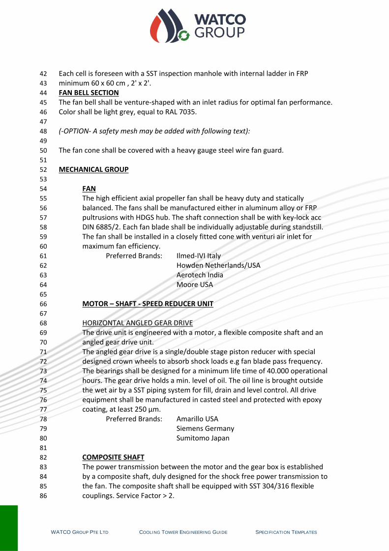
Each cell is foreseen with a SST inspection manhole with internal ladder in FRP 42 minimum 60 x 60 cm , 2' x 2'. 43 FAN BELL SECTION 44 The fan bell shall be venture‐shaped with an inlet radius for optimal fan performance. 45 Color shall be light grey, equal to RAL 7035. 46 47 (‐OPTION‐ A safety mesh may be added with following text): 48 49 The fan cone shall be covered with a heavy gauge steel wire fan guard. 50 51 MECHANICAL GROUP 52 53
FAN 54 The high efficient axial propeller fan shall be heavy duty and statically 55 balanced. The fans shall be manufactured either in aluminum alloy or FRP 56 pultrusions with HDGS hub. The shaft connection shall be with key‐lock acc 57 DIN 6885/2. Each fan blade shall be individually adjustable during standstill. 58 The fan shall be installed in a closely fitted cone with venturi air inlet for 59 maximum fan efficiency. 60
Preferred Brands: Ilmed‐IVI Italy 61 Howden Netherlands/USA 62 Aerotech India 63 Moore USA 64
65 MOTOR – SHAFT ‐ SPEED REDUCER UNIT 66 67 HORIZONTAL ANGLED GEAR DRIVE 68 The drive unit is engineered with a motor, a flexible composite shaft and an 69 angled gear drive unit. 70 The angled gear drive is a single/double stage piston reducer with special 71 designed crown wheels to absorb shock loads e.g fan blade pass frequency. 72 The bearings shall be designed for a minimum life time of 40.000 operational 73 hours. The gear drive holds a min. level of oil. The oil line is brought outside 74 the wet air by a SST piping system for fill, drain and level control. All drive 75 equipment shall be manufactured in casted steel and protected with epoxy 76 coating, at least 250 μm. 77
Preferred Brands: Amarillo USA 78 Siemens Germany 79 Sumitomo Japan 80
81 COMPOSITE SHAFT 82 The power transmission between the motor and the gear box is established 83 by a composite shaft, duly designed for the shock free power transmission to 84 the fan. The composite shaft shall be equipped with SST 304/316 flexible 85 couplings. Service Factor > 2. 86

WATCO GROUP PTE LTD COOLING TOWER ENGINEERING GUIDE SPECIFICATION TEMPLATES
Preferred Brands: ADDAR/Rexnord USA/EU 87 88
MOTOR 89 The motor shall be TEFC/ICE class II efficiency, protection IP 55 upwards, 90 insulation class F5 with enclosed ball bearings and a service factor of > 1.12. 91 The motor power shall be: ____ V; _____ Hz. Bearing life time > 40.000 hrs of 92 operation. 93
Preferred Brands: ABB EU/Asia 94 Electramo Belgium 95
Brook‐Crompton UK 96 WEG EU/America 97
98 DRIVE FRAME 99 The frame for the mechanical components is in HDGS or SST and holds the 100 setup points for motor and gear drive as well 1 or 2 shaft protectors. 101
102 (‐ OPTION – Instead of traditional motor‐shaft‐gear drive combination, selection (of 103 smaller units) may look at an integrated unit which would be below specification 104 text): 105
106 COMPACT GEAR IN‐LINE DIRECT DRIVE 107 The fan drive shall be a compact angled gear reducer drive (for fans 1800 – 108 3360 mm) with single stage crown‐wheel and piston with double bearing. The 109 bearings shall be designed for a minimum life time of 40.000 operational 110 hours. The motor is directly coupled to the piston shaft. The input and output 111 shaft are equipped with top brand seals. The gear drive holds a min. level of 112 oil. The oil level is to be checked with an internal dipstick. Follow the 113 operational instructions for oil change. All drive equipment shall be 114 manufactured in casted steel and protected with epoxy coating, at least 250 115 μm. Service Factor > 2. 116
Preferred Brands: Bockwoldt Germany 117 118 WATER DISTRIBUTION SYSTEM 119 The cooling tower shall have an inlet internal piping #40/PN10 with DIN/ANSI 120 connection flange, which divides the water equally over the wet section. The fill will 121 be watered by a sufficient number of non clogging spray nozzles. The nozzles shall be 122 manufactured by the cooling tower supplier for single source and responsibility. 123 Depending of the inlet temperatures the piping system is made in PVC, ABS, FRP or 124 SST. 125 126 HEAT EXCHANGE INFILL 127 128 CENTRA PACK – for clean treated cooling water. 129 The cooling tower fill shall be in PVC or ABS, cross fluted film type design Y‐15 for 130 optimum heat transfer efficiency. The fill thickness shall be at least 280 μm and shall 131

WATCO GROUP PTE LTD COOLING TOWER ENGINEERING GUIDE SPECIFICATION TEMPLATES
be manufactured by the cooling tower manufacturer for single source and 132 responsibility. The film shall be self‐extinguishing for the fire resistance with a flame 133 spread rating of 5 per ASTM E84‐81a. It shall also be resistant to rot, decay and 134 biological attack. For standard operating temperatures the fill shall be able to 135 withstand a continuous water temperature of 55 ºC for PVC and 80 ºC for ABS. 136 137 (‐OPTION‐ Instead of film fill, selection may call for splash fill with following text) 138 139 CENTRA FILL ‐ for contaminated cooling water. 140 The infill pack consists of a certain level of triangle corrugated profiles. The triangle 141 bars are in cross section towards each other in the tower structure. Due to the 142 extreme labyrinth function of the positions of the corrugated profiles the air flows 143 with intense turbulence in the infill structure. In the same time the water droplets do 144 attach to the profiles and free fall randomly down to lower levels were it is split over 145 the profile angles. The large holdup time of the water in the tower create an efficient 146 exchange of the heat load. 147 148 ELIMINATORS 149 CENTRA DECK 150 The eliminators shall be in UV‐protected PVC or ABS double angle labyrinth design to 151 avoid water in droplets leaving the tower via the exhaust air stream. The efficiency 152 of the drift eliminator shall be < 0.005 % of the circulating water volume. 153 154 AIR INLET LOUVRES 155 LOUVERS: 156 The air inlet louver avoid splash out of the water and shall be of FRP in SST 304 or 157 316 holders. The louvers shall be in sections and easily removable. 158 159 (‐OPTION‐ Instead of louvers, selection may call for PVC screens with following text) 160 161 SCREENS: 162 The inlet screens avoid splash out of the water as well sun light impact and an 163 additional noise reduction of the falling water and shall be of a FRP fame with 164 labyrinth elements in PVC. 165 166 ‐OPTIONAL ITEMS‐ 167 168 WATER BASIN: 169 The water basin shall be manufactured in rigid FRP sectional parts for easy 170 installation, long life and durability. Standard basin accessories shall be included as 171 inlet flange with strainer, drain socket and overflow socket. The basin is designed to 172 holding a minimum required water volume for low operation weight and easy 173 maintenance. Vital points are slope designed for full drainage. Color shall be light 174 grey, equal to RAL 7035. 175 176

WATCO GROUP PTE LTD COOLING TOWER ENGINEERING GUIDE SPECIFICATION TEMPLATES
(CAGE) LADDER / STAIRCASE, HANDRAIL: 177 To be made from FRP pultruted profiles according international DIN/OSHA.SAME 178 standards. 179 180 VIBRATION SWITCHES. 181 182 FLOAT VALVES or INDUCTIVE LEVEL CONTROL WITH FILL VALVE. 183 184
Disclaimer: 185
Due to continuous improvements in research & development of our products, the data shown in this catalog are 186 subject to change without notice. Please contact your local dealer or www.watco-group.com for updated 187 information. This paper was designed in October 2015. 188
WATCO GROUP PTE LTD COOLING TOWER ENGINEERING GUIDE SPECIFICATION TEMPLATES
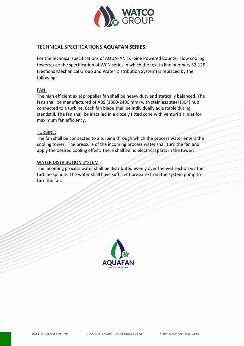
TECHNICAL SPECIFICATIONS AQUAFAN SERIES:
For the technical specifications of AQUAFAN Turbine Powered Counter Flow cooling towers, use the specification of WCN series in which the text in line numbers 52‐125 (Sections Mechanical Group and Water Distribution System) is replaced by the following:
FAN: The high efficient axial propeller fan shall be heavy duty and statically balanced. The fans shall be manufactured of ABS (1800‐2400 mm) with stainless steel (304) hub connected to a turbine. Each fan blade shall be individually adjustable during standstill. The fan shall be installed in a closely fitted cone with venturi air inlet for maximum fan efficiency. TURBINE: The fan shall be connected to a turbine through which the process water enters the cooling tower. The pressure of the incoming process water shall turn the fan and apply the desired cooling effect. There shall be no electrical parts in the tower. WATER DISTRIBUTION SYSTEM The incoming process water shall be distributed evenly over the wet section via the turbine spindle. The water shall have sufficient pressure from the system pump to turn the fan.

WATCO GROUP PTE LTD COOLING TOWER ENGINEERING GUIDE COMPANY PROFILE
CompanyProfile
Company Name : WATCO Group PTE LTD Company Type : Limited Exempt Private Company Registered in : Singapore Registration number : 201322647W Company Address : Tower 1, Raffles Place #44‐02
Singapore 048616 Telephone +65‐31581332
Subsidiaries : WACON International (HK) Ltd WACON Guangzhou Trading Ltd
Directors/shareholders : Hubert Poels, Managing Director sg.linkedin.com/in/hubertpoels/
Henk Janssen, Operations Director sg.linkedin.com/in/henkjanssen/
Employees : 12 Annual Turnover : US$ 2,500,000 Activities : Industrial water cooling solutions
Product lines : • Cooling towers
• Motorless hydro‐powered cooling towers • On‐line brushing systems for shell and tube
heat exchangers • Enthalpy recovery units
Brief History : • Founded as WACON‐AQUAVEN BV in 1984 in
Netherlands, specialist in cooling towers. • In 2002 moved company headquarters to
Hong Kong with focus on cooling tower project engineering, consulting and component supply
• In 2013 established new head quarters in Singapore

WATCO GR
ROUP PTE LTD
Backgro
Compan
und
ny Websites
COOLING TO
:
:
OWER ENGINEER
The Grouengineerengineerbeen givemotorleson‐line c Main maEast. www.wawww.wawww.aquwww.eqo
RING GUIDE
up has a lonring. In recering of energen prioritiesss cooling toleaning syst
rkets are in
tco‐group.ccon.co uafan.co obrush.co
ng experiencnt years thegy saving tes and resultowers and htems for he
n South East
co
C
ce in cooline developmechnologiested in the lahigh performeat exchang
t Asia and M
OMPANY PROFIL
g tower ment and s has aunch of mance ers.
Middle
LE