5V and 3.3V Supply Monitor, Watchdog Timer, Manual Reset ...
AN0015.1: EFM32 and EFR32 Series 1Watchdog
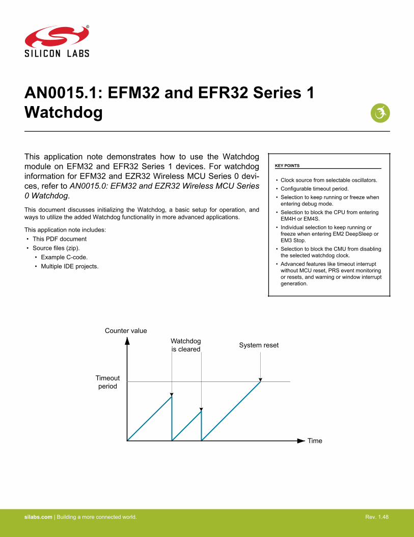
This application note demonstrates how to use the Watchdogmodule on EFM32 and EFR32 Series 1 devices. For watchdoginformation for EFM32 and EZR32 Wireless MCU Series 0 devi-ces, refer to AN0015.0: EFM32 and EZR32 Wireless MCU Series0 Watchdog.This document discusses initializing the Watchdog, a basic setup for operation, andways to utilize the added Watchdog functionality in more advanced applications.
This application note includes:• This PDF document• Source files (zip).
• Example C-code.• Multiple IDE projects.
KEY POINTS
• Clock source from selectable oscillators.• Configurable timeout period.• Selection to keep running or freeze when
entering debug mode.• Selection to block the CPU from entering
EM4H or EM4S.• Individual selection to keep running or
freeze when entering EM2 DeepSleep orEM3 Stop.
• Selection to block the CMU from disablingthe selected watchdog clock.
• Advanced features like timeout interruptwithout MCU reset, PRS event monitoringor resets, and warning or window interruptgeneration.
System resetWatchdog is cleared
Counter value
Timeout period
Time
silabs.com | Building a more connected world. Rev. 1.48

1. Device Compatibility
This application note supports multiple device families, and some functionality is different depending on the device.
MCU Series 1 consists of:• EFM32 Jade Gecko (EFM32JG1/EFM32JG12/EFM32JG13)• EFM32 Pearl Gecko (EFM32PG1/EFM32PG12/EFM32PG13)• EFM32 Giant Gecko (EFM32GG11)
Wireless SoC Series 1 consists of:• EFR32 Blue Gecko (EFR32BG1/EFR32BG12/EFR32BG13)• EFR32 Flex Gecko (EFR32FG1/EFR32FG12/EFR32FG13)• EFR32 Mighty Gecko (EFR32MG1/EFR32MG12/EFR32MG13)
AN0015.1: EFM32 and EFR32 Series 1 WatchdogDevice Compatibility
silabs.com | Building a more connected world. Rev. 1.48 | 2
2. Watchdog Theory
2.1 General Theory
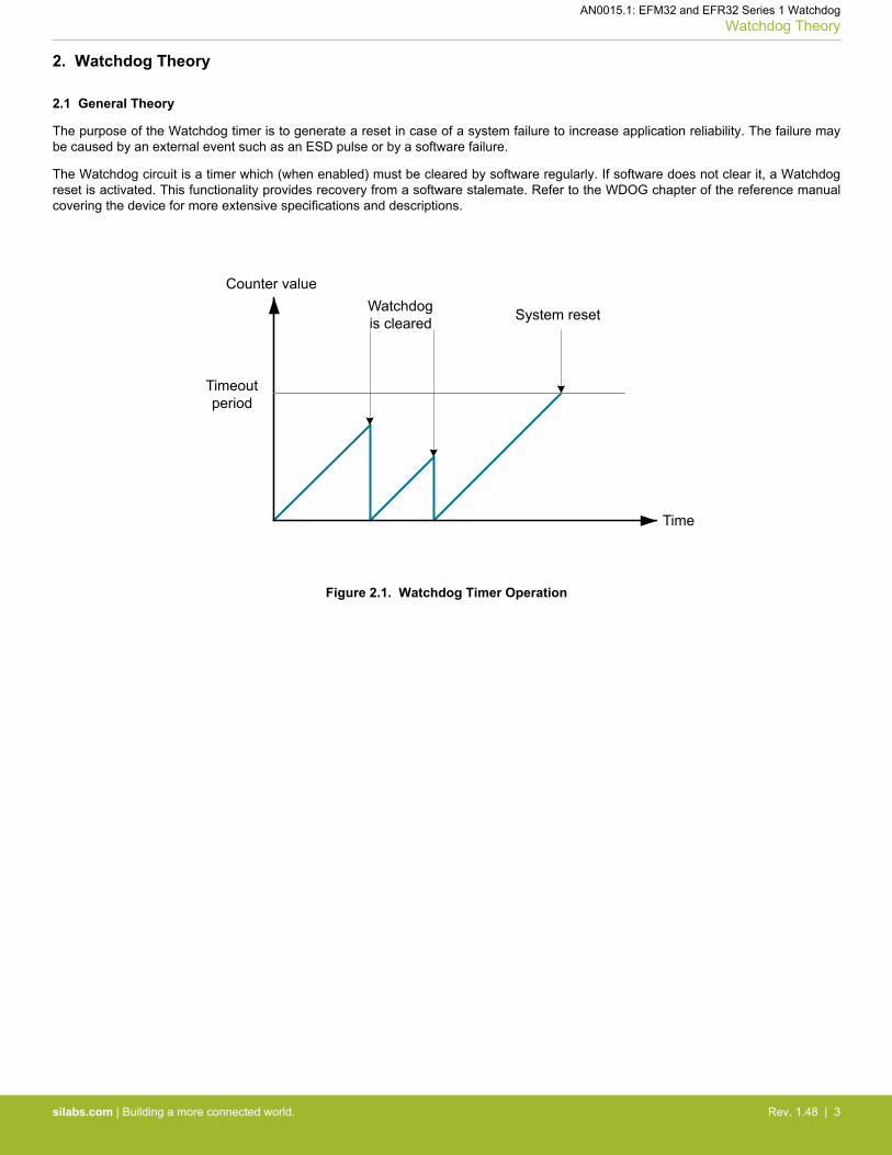
The purpose of the Watchdog timer is to generate a reset in case of a system failure to increase application reliability. The failure maybe caused by an external event such as an ESD pulse or by a software failure.
The Watchdog circuit is a timer which (when enabled) must be cleared by software regularly. If software does not clear it, a Watchdogreset is activated. This functionality provides recovery from a software stalemate. Refer to the WDOG chapter of the reference manualcovering the device for more extensive specifications and descriptions.
System resetWatchdog is cleared
Counter value
Timeout period
Time
Figure 2.1. Watchdog Timer Operation
AN0015.1: EFM32 and EFR32 Series 1 WatchdogWatchdog Theory
silabs.com | Building a more connected world. Rev. 1.48 | 3

2.2 Watchdog Reset
The Watchdog timer on the EFM32 (WDOG) is a Low Energy Peripheral module that can be configured to generate a system reset inthe case that it is not cleared by software before the given deadline.
When the Watchdog is cleared (often also referred to as feeding or petting the Watchdog), it means that the value counted to by thetimer is reset to zero. This is done by software and is the normal procedure when the system is running correctly.
When the Watchdog timer reaches a certain threshold value, it will generate a system reset. This indicates that the system is not run-ning correctly and that the CPU has failed to reset the Watchdog in a timely manner. In this case, the Watchdog offers a safe way toreturn the system to a known state through system reset.
Systemreset
Watchdog counting
Watchdog enabled
Watchdog timeout
Watchdog cleared
Figure 2.2. Watchdog State Diagram
AN0015.1: EFM32 and EFR32 Series 1 WatchdogWatchdog Theory
silabs.com | Building a more connected world. Rev. 1.48 | 4
3. Watchdog Configuration
3.1 Choice of Clock Source
On all devices, the WDOG can be configured to use the following clock sources: LFRCO, LFXO or ULFRCO. The EFM32xG12/13 andEFR32xG12/13 devices can additionally use the HFCORECLK as a Watchdog clock source, which is available in EM0 and EM1.
ULFRCO (Ultra Low Frequency RC Oscillator) is a separate and dedicated Watchdog 1 kHz RC oscillator that also runs in EM3. Thisoscillator is always enabled and is included in all current consumption numbers.
It is important to take into consideration the ULFRCO accuracy. The oscillator offers extremely low energy consumption, but has re-duced accuracy. It is therefore advisable to time the Watchdog resets with considerable margin to avoid unwanted system resets. Forexample, the EFM32PG1 Pearl Gecko data sheet specifies that the ULFRCO can vary between 0.95 and 1.07 kHz. This means that thetimeout period may vary from -6.6% to +5.3% of the desired period, device to device. This is important to remember when testing soft-ware on one device that will later run on other devices. A specific timeout period might give good results on one device, but may gener-ate unwanted system resets on a device with a slightly different ULFRCO frequency. The ULFRCO is available down to EM4S.
The LFRCO and LFXO have higher accuracy, but in turn need more energy to operate. They are also shared with other system devicesand first need be enabled in software. For EFM32PG1 devices, the LFRCO (32.768kHz) can vary between 30.474 and 34.243 kHz(ENVREF = 1 in CMU_LFRCOCTRL, ambient temperature = 85°C), which means that the timeout period may vary from -7.5% and4.5% of the desired period. The LFRCO is available down to EM2. The LFXO clock (32.768kHz) accuracy will be dependent on thecrystal specification, but is generally more accurate than either the LFRCO or the ULFRCO.
Refer to the specific device data sheet for more extensive information on oscillator accuracy.
All of the Watchdog oscillators have uncertainty that should be accounted for during system design to guarantee predictable systembehavior. The clock sources for the Watchdog peripheral are also shared with other system devices and first need to be enabled insoftware. When using them as Watchdog clock sources, it is critical that they are not disabled in other parts of the software.
In order to access the WDOG from the CPU, the HFCORECLK_LE clock gate must be enabled in the CMU (Clock Management Unit).
3.2 Timeout Periods
The Watchdog offers a wide range of timeout periods to select from during system design. The PERSEL field in WDOGn_CTRL is usedto divide the selected watchdog clock, and the timeout for the watchdog timer can be calculated with the formula:
TTIMEOUT = 23+PERSEL + 1f
A total of 16 levels offer periods between 9 to 256k cycles of the chosen Watchdog clock source. (i.e. from ~274 μs for 32768 Hz clocksource to ~262 s for 1000 Hz clock source).
3.3 Energy Mode Integration
The Watchdog contains extensive support for integration with the different Energy Modes and energy consumption minimization. Differ-ent register values toggle if the Watchdog is to keep running in respectively EM2 and/or EM3, and whether or not the system is allowedto enter EM4H or EM4S. For example, the Watchdog can be set to keep counting in EM2, but not during EM3. When resuming fromEM3, the Watchdog will keep counting from the previous counter value.
The registers are:
• WDOG_CTRL_EM2RUN — toggles if the Watchdog timer is to keep running when the system has entered EM2.• WDOG_CTRL_EM3RUN — toggles if the Watchdog timer is to keep running when the system has entered EM3.• WDOG_CTRL_EM4BLOCK — toggles if the system is disabled by the Watchdog from entering EM4H or EM4S, where all the Watchdog
clock sources are disabled.
3.4 Debug Functionality
The watchdog timer can either keep running or be frozen when the device is halted by a debugger. This configuration is done throughthe DEBUGRUN bit in WDOGn_CTRL. When code execution is resumed, the watchdog will continue counting from the previous value.
AN0015.1: EFM32 and EFR32 Series 1 WatchdogWatchdog Configuration
silabs.com | Building a more connected world. Rev. 1.48 | 5
3.5 Watchdog Clearing Considerations
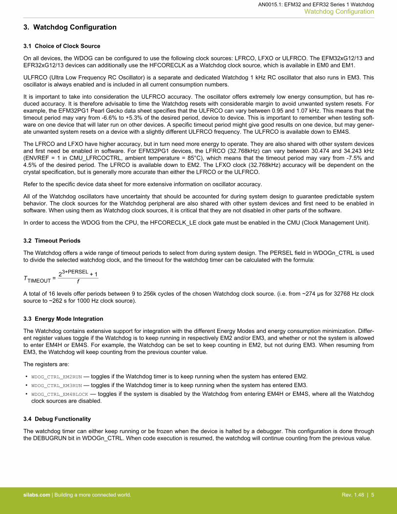
All the available Watchdog clocks are asynchronous to the CPU clock except for the HFCORECLK on EFM32xG12/13 orEFR32xG12/13 devices. When using clock sources other than HFCORECLK, synchronization between the CPU and the Watchdogclock domains should therefore be taken into consideration when using the Watchdog. It generally takes 3 WDOGCLK cycles from theinstruction is executed until the correct value enters the WDOG registers. To guarantee that the Watchdog timer always is cleared cor-rectly, all clear operations of the Watchdog timer should be written 4 WDOGCLK cycles before timeout (3 + 1 clock of uncertainty). Thisis critical to remember especially when using short timeout periods. For example, when operating with a Watchdog period of 9WDOGCLK cycles, the first clear should be no later than 3.3 WDOGCLK cycles (9 – 4 – 33%) after the Watchdog is enabled. Theinterval between all subsequent Watchdog instructions should be no more than 5.3 WDOGCLK cycles (9 – 1 uncertainty – 33%). Whenusing a clock source different from the ULFRCO, the safety margin should be changed according to the accuracy of that oscillator. Thisshould encourage the use of caution when implementing strict timing schemes for Watchdog resetting. For more information on access-ing asynchronous registers and on oscillator accuracy, refer to the Reference Manual for the device.
System reset
Counter value
Timeout period of 9 WDC
Time01
23
45
6
01
23
45
67
89
Watchdog clear
executed
Watchdog timer
cleared Watchdog timeout
Watchdog enabled
Figure 3.1. Discrete Representation of the Watchdog Timer Operation
To effectively determine when to issue a Watchdog reset in software, it is important to have good knowledge of its timing characteris-tics. The Watchdog timeout period need be longer than the longest possible execution path through the software initialization and mainloop. The execution path length must also include the expected interrupts and their handler's run times. This is to ensure that a largenumber of interrupts is not regarded by the Watchdog as a system stalemate.
3.6 Reset Cause Detection
The RMU (Reset Management Unit) contains a register that holds information on what caused the last system reset. This register pro-vides a method to detect if the Watchdog has triggered a reset. This information can be very useful in applications using the Watchdog,or to check if the Watchdog generates unwanted system resets. A basic use of the functionality is shown in the software examples. Thiscan also be used to check if the Watchdog triggered a reset even in applications where the watchdog is not in use. This is a secure wayto ensure safe operation even when the Watchdog is enabled accidentally. Alternatively, the watchdog register can be locked duringstartup. For more information, refer to the RMU and WDOG chapters in the Reference Manual for the device.
3.7 Register Locking
Some functionality is added to keep other parts of the system from interfering with the Watchdog. Different register entries can be set toprevent disablement of the chosen clock source, and the Watchdog register can be locked so that no modifications can be made to it.The registers are:
• WDOG_CTRL_SWOSCBLOCK — when set, the Watchdog blocks all software from disabling the oscillator driving the WDOG timer.• WDOG_CTRL_LOCK — when set, the WDOG_CTRL register is locked and cannot be altered. The register should be set using the func-
tion void WDOG_Lock(void) from emlib. The lock can only be disabled by a system reset.
AN0015.1: EFM32 and EFR32 Series 1 WatchdogWatchdog Configuration
silabs.com | Building a more connected world. Rev. 1.48 | 6
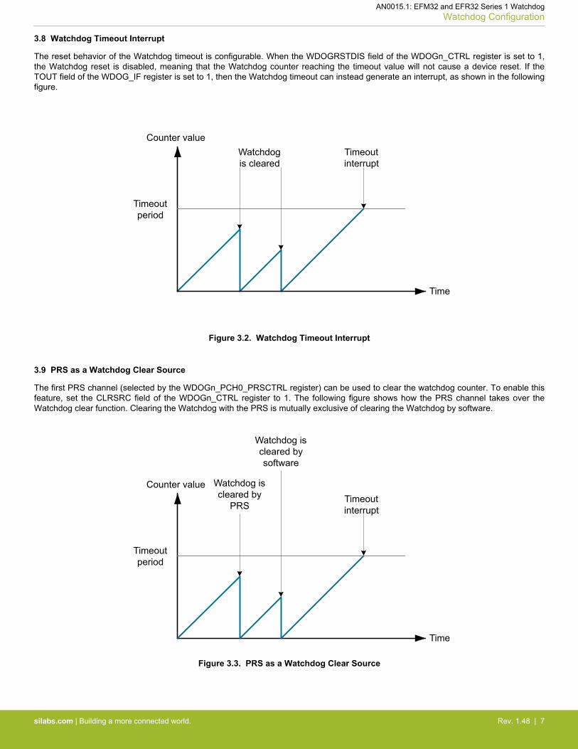
3.8 Watchdog Timeout Interrupt
The reset behavior of the Watchdog timeout is configurable. When the WDOGRSTDIS field of the WDOGn_CTRL register is set to 1,the Watchdog reset is disabled, meaning that the Watchdog counter reaching the timeout value will not cause a device reset. If theTOUT field of the WDOG_IF register is set to 1, then the Watchdog timeout can instead generate an interrupt, as shown in the followingfigure.
Timeout interrupt
Watchdog is cleared
Counter value
Timeout period
Time
Figure 3.2. Watchdog Timeout Interrupt
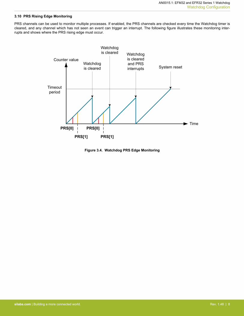
3.9 PRS as a Watchdog Clear Source
The first PRS channel (selected by the WDOGn_PCH0_PRSCTRL register) can be used to clear the watchdog counter. To enable thisfeature, set the CLRSRC field of the WDOGn_CTRL register to 1. The following figure shows how the PRS channel takes over theWatchdog clear function. Clearing the Watchdog with the PRS is mutually exclusive of clearing the Watchdog by software.
Timeout interrupt
Watchdog is cleared by software
Counter value
Timeout period
Time
Watchdog is cleared by
PRS
Figure 3.3. PRS as a Watchdog Clear Source
AN0015.1: EFM32 and EFR32 Series 1 WatchdogWatchdog Configuration
silabs.com | Building a more connected world. Rev. 1.48 | 7
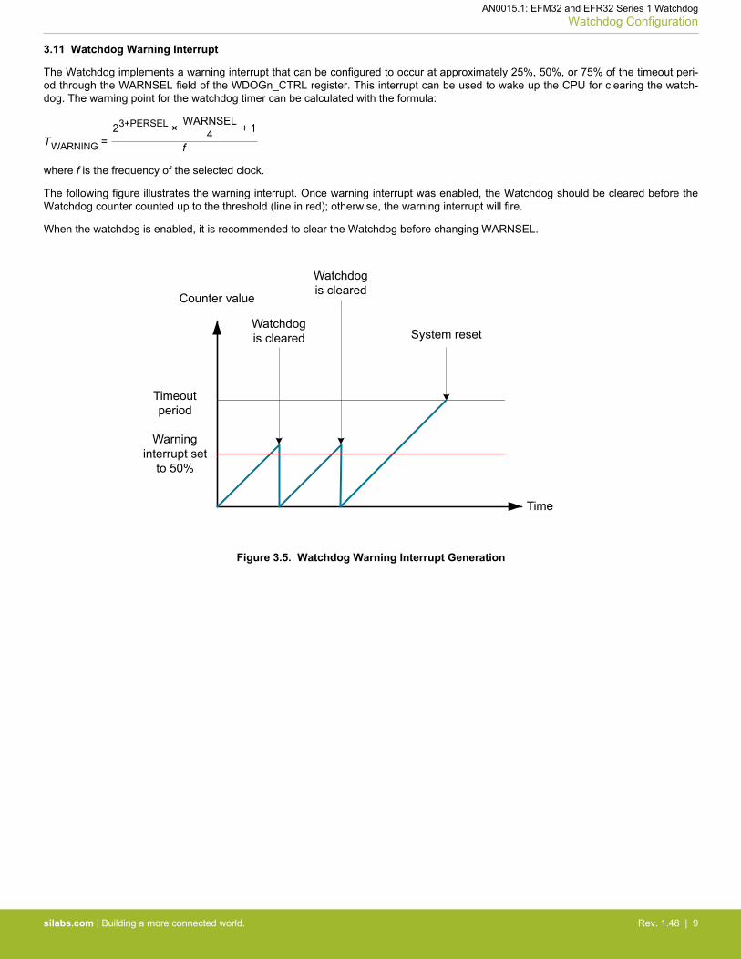
3.10 PRS Rising Edge Monitoring
PRS channels can be used to monitor multiple processes. If enabled, the PRS channels are checked every time the Watchdog timer iscleared, and any channel which has not seen an event can trigger an interrupt. The following figure illustrates these monitoring inter-rupts and shows where the PRS rising edge must occur.
Timeout period
Counter value
System resetWatchdog is cleared
Time
Watchdog is cleared Watchdog
is cleared and PRS interrupts
PRS[0]
PRS[1]
PRS[0]
PRS[1]
Figure 3.4. Watchdog PRS Edge Monitoring
AN0015.1: EFM32 and EFR32 Series 1 WatchdogWatchdog Configuration
silabs.com | Building a more connected world. Rev. 1.48 | 8
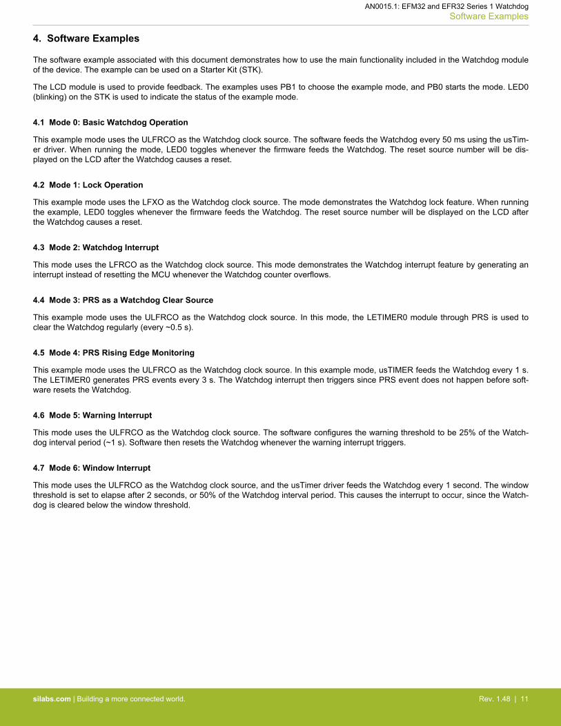
3.11 Watchdog Warning Interrupt
The Watchdog implements a warning interrupt that can be configured to occur at approximately 25%, 50%, or 75% of the timeout peri-od through the WARNSEL field of the WDOGn_CTRL register. This interrupt can be used to wake up the CPU for clearing the watch-dog. The warning point for the watchdog timer can be calculated with the formula:
TWARNING =23+PERSEL × WARNSEL
4 + 1
f
where f is the frequency of the selected clock.
The following figure illustrates the warning interrupt. Once warning interrupt was enabled, the Watchdog should be cleared before theWatchdog counter counted up to the threshold (line in red); otherwise, the warning interrupt will fire.
When the watchdog is enabled, it is recommended to clear the Watchdog before changing WARNSEL.
Timeout period
Counter value
System resetWatchdog is cleared
Time
Watchdog is cleared
Warning interrupt set
to 50%
Figure 3.5. Watchdog Warning Interrupt Generation
AN0015.1: EFM32 and EFR32 Series 1 WatchdogWatchdog Configuration
silabs.com | Building a more connected world. Rev. 1.48 | 9

3.12 Watchdog Window Interrupt
This interrupt occurs when the Watchdog is cleared below a certain threshold. This threshold is given by the formula:
TWINDOW =23+PERSEL × WINSEL
4 + 1
f
where f is the frequency of the selected clock.
This value will be approximately 12.5%, 25%, 37.5%, 50%, 62.5%, 75%, or 87.5% of the timeout value based on the WINSEL field ofthe WDOGn_CTRL register. The following figure illustrates the window and the watchdog timeout period. Once the window interrupt isenabled, clearing the Watchdog too early causes the window interrupt to fire.
When the watchdog is enabled, it is recommended to clear the Watchdog before changing WINSEL.
Timeout period
Counter value
System reset
Watchdog is cleared
by software
Time
Watchdog is cleared by software and window interrupt
triggers
Window interrupt set
to 50%
Figure 3.6. Watchdog Window Interrupt Generation
AN0015.1: EFM32 and EFR32 Series 1 WatchdogWatchdog Configuration
silabs.com | Building a more connected world. Rev. 1.48 | 10
4. Software Examples
The software example associated with this document demonstrates how to use the main functionality included in the Watchdog moduleof the device. The example can be used on a Starter Kit (STK).
The LCD module is used to provide feedback. The examples uses PB1 to choose the example mode, and PB0 starts the mode. LED0(blinking) on the STK is used to indicate the status of the example mode.
4.1 Mode 0: Basic Watchdog Operation
This example mode uses the ULFRCO as the Watchdog clock source. The software feeds the Watchdog every 50 ms using the usTim-er driver. When running the mode, LED0 toggles whenever the firmware feeds the Watchdog. The reset source number will be dis-played on the LCD after the Watchdog causes a reset.
4.2 Mode 1: Lock Operation
This example mode uses the LFXO as the Watchdog clock source. The mode demonstrates the Watchdog lock feature. When runningthe example, LED0 toggles whenever the firmware feeds the Watchdog. The reset source number will be displayed on the LCD afterthe Watchdog causes a reset.
4.3 Mode 2: Watchdog Interrupt
This mode uses the LFRCO as the Watchdog clock source. This mode demonstrates the Watchdog interrupt feature by generating aninterrupt instead of resetting the MCU whenever the Watchdog counter overflows.
4.4 Mode 3: PRS as a Watchdog Clear Source
This example mode uses the ULFRCO as the Watchdog clock source. In this mode, the LETIMER0 module through PRS is used toclear the Watchdog regularly (every ~0.5 s).
4.5 Mode 4: PRS Rising Edge Monitoring
This example mode uses the ULFRCO as the Watchdog clock source. In this example mode, usTIMER feeds the Watchdog every 1 s.The LETIMER0 generates PRS events every 3 s. The Watchdog interrupt then triggers since PRS event does not happen before soft-ware resets the Watchdog.
4.6 Mode 5: Warning Interrupt
This mode uses the ULFRCO as the Watchdog clock source. The software configures the warning threshold to be 25% of the Watch-dog interval period (~1 s). Software then resets the Watchdog whenever the warning interrupt triggers.
4.7 Mode 6: Window Interrupt
This mode uses the ULFRCO as the Watchdog clock source, and the usTimer driver feeds the Watchdog every 1 second. The windowthreshold is set to elapse after 2 seconds, or 50% of the Watchdog interval period. This causes the interrupt to occur, since the Watch-dog is cleared below the window threshold.
AN0015.1: EFM32 and EFR32 Series 1 WatchdogSoftware Examples
silabs.com | Building a more connected world. Rev. 1.48 | 11
5. Revision History
5.1 Revision 1.09
2017-09-12
Initial revision.
AN0015.1: EFM32 and EFR32 Series 1 WatchdogRevision History
silabs.com | Building a more connected world. Rev. 1.48 | 12

http://www.silabs.com
Silicon Laboratories Inc.400 West Cesar ChavezAustin, TX 78701USA
Simplicity StudioOne-click access to MCU and wireless tools, documentation, software, source code libraries & more. Available for Windows, Mac and Linux!
IoT Portfoliowww.silabs.com/IoT
SW/HWwww.silabs.com/simplicity
Qualitywww.silabs.com/quality
Support and Communitycommunity.silabs.com
DisclaimerSilicon Labs intends to provide customers with the latest, accurate, and in-depth documentation of all peripherals and modules available for system and software implementers using or intending to use the Silicon Labs products. Characterization data, available modules and peripherals, memory sizes and memory addresses refer to each specific device, and "Typical" parameters provided can and do vary in different applications. Application examples described herein are for illustrative purposes only. Silicon Labs reserves the right to make changes without further notice and limitation to product information, specifications, and descriptions herein, and does not give warranties as to the accuracy or completeness of the included information. Silicon Labs shall have no liability for the consequences of use of the information supplied herein. This document does not imply or express copyright licenses granted hereunder to design or fabricate any integrated circuits. The products are not designed or authorized to be used within any Life Support System without the specific written consent of Silicon Labs. A "Life Support System" is any product or system intended to support or sustain life and/or health, which, if it fails, can be reasonably expected to result in significant personal injury or death. Silicon Labs products are not designed or authorized for military applications. Silicon Labs products shall under no circumstances be used in weapons of mass destruction including (but not limited to) nuclear, biological or chemical weapons, or missiles capable of delivering such weapons.
Trademark InformationSilicon Laboratories Inc.® , Silicon Laboratories®, Silicon Labs®, SiLabs® and the Silicon Labs logo®, Bluegiga®, Bluegiga Logo®, Clockbuilder®, CMEMS®, DSPLL®, EFM®, EFM32®, EFR, Ember®, Energy Micro, Energy Micro logo and combinations thereof, "the world’s most energy friendly microcontrollers", Ember®, EZLink®, EZRadio®, EZRadioPRO®, Gecko®, ISOmodem®, Micrium, Precision32®, ProSLIC®, Simplicity Studio®, SiPHY®, Telegesis, the Telegesis Logo®, USBXpress®, Zentri and others are trademarks or registered trademarks of Silicon Labs. ARM, CORTEX, Cortex-M3 and THUMB are trademarks or registered trademarks of ARM Holdings. Keil is a registered trademark of ARM Limited. All other products or brand names mentioned herein are trademarks of their respective holders.