WASTE SYSTEMS (PLUMBING III) - freeinfosociety.com · WASTE SYSTEMS (PLUMBING III) ... No-hub pipe...
101
SUBCOURSE EDITION EN5112 A WASTE SYSTEMS (PLUMBING III)
-
Upload
truongcong -
Category
Documents
-
view
213 -
download
0
Transcript of WASTE SYSTEMS (PLUMBING III) - freeinfosociety.com · WASTE SYSTEMS (PLUMBING III) ... No-hub pipe...
SUBCOURSE EDITION EN5112 A
WASTE SYSTEMS (PLUMBING III)
US ARMY PLUMBER MOS 51K SKILL LEVELS 1 AND 2 COURSE
WASTE SYSTEMS (PLUMBING III)
SUBCOURSE EN5112
US Army Engineer School
Fort Leonard Wood, Missouri
Eleven Credit Hours
GENERAL The waste system subcourse, part of the Plumber MOS 51K Skill Levels 1 and 2 course, is designated to teach those tasks necessary to prepare, connect, and install pipes in a waste system. The subcourse is presented in two lessons, each corresponding to a terminal objective as indicated below. Lesson 1: WASTE SYSTEMS AND MATERIALS OBJECTIVE: Describe the procedures for preparing cast-iron pipe for installation. TASK: 051-248-1003, Install cast-iron pipe. CONDITIONS: Given subcourse booklet EN5112. You will work at your own pace and in your own selected environment with no supervision. STANDARDS: Within approximately 3 hours, you should be able to study the lesson resources, answer the practice exercise questions, and select the correct response for each examination questions. You must respond correctly to 70 percent of the examination questions in order to receive credit for the subcourse.
i
Lesson 2: WASTE SYSTEM ROUGHING-IN OBJECTIVE: Describe the procedures for installing cast-iron pipes for a rough-in waste system. TASK: Task 051-248-1003, Install cast-iron pipe (connect and install pipe). CONDITIONS: Given subcourse booklet EN5112. You will work at your own pace and in your own environment with no supervision. STANDARDS: Within approximately 8 hours, you should be able to study the lesson resources, answer the practice exercise questions, and select the correct response for each examination question. You must respond correctly to 70 percent of the examination questions in order to receive credit for the subcourse.
ii
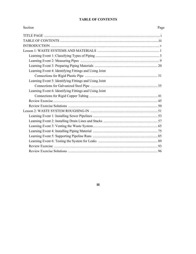
TABLE OF CONTENTS Section Page TITLE PAGE ................................................................................................................................... i TABLE OF CONTENTS ...............................................................................................................iii INTRODUCTION ........................................................................................................................... v Lesson 1: WASTE SYSTEMS AND MATERIALS ...................................................................... 1 Learning Event 1: Classifying Types of Piping ........................................................................ 3 Learning Event 2: Measuring Pipes ......................................................................................... 9 Learning Event 3: Preparing Piping Materials ....................................................................... 20 Learning Event 4: Identifying Fittings and Using Joint Connections for Rigid Plastic Pipe .................................................................................. 31 Learning Event 5: Identifying Fittings and Using Joint Connections for Galvanized Steel Pipe ............................................................................ 35 Learning Event 6: Identifying Fittings and Using Joint Connections for Rigid Copper Tubing ............................................................................. 41 Review Exercise ...................................................................................................................... 45 Review Exercise Solutions ..................................................................................................... 50 Lesson 2: WASTE SYSTEM ROUGHING-IN ............................................................................ 51 Learning Event 1: Installing Sewer Pipelines ......................................................................... 53 Learning Event 2: Installing Drain Lines and Stacks ............................................................. 57 Learning Event 3: Venting the Waste System......................................................................... 65 Learning Event 4: Installing Piping Material ......................................................................... 75 Learning Event 5: Supporting Pipeline Runs ......................................................................... 85 Learning Event 6: Testing the System for Leaks ................................................................... 89 Review Exercise ..................................................................................................................... 93 Review Exercise Solutions ..................................................................................................... 96
iii

INTRODUCTION A plumber must know how to join and install different kinds of pipe to complete a waste system in a building. Made of different materials, these pipes must sometimes be cut and their ends prepared to take fittings. The pipe-to-pipe or pipe-to-fitting connections are made with lead, collars, threads, solvent cement, and solder, depending on the pipe material used. As the pipe system is installed, it must be supported with hangers and holders. Sometimes a plumber must cut into the building structure to install the waste and vent pipeline runs for lavatories, sinks, water closets, and urinals. Once the system of rough-in waste pipelines with venting is installed, it is tested for leaks.
Lesson 1 WASTE SYSTEMS AND MATERIALS
OBJECTIVE At the end of this lesson, you will be able to describe the procedures for preparing cast-iron pipe for installation. TASK Task 051-248-1003, Install cast-iron pipe CONDITIONS You will have subcourse booklet EN5112. You will work at your own pace and in your own selected environment with no supervision. STANDARDS Within approximately 3 hours, you should be able to study the lesson resources, answer the practice exercise questions, and select the correct response for each examination question. You must respond correctly to 70 percent of the examination questions in order to receive credit for the subcourse. REFERENCES FM 5-51K1/2 TM 5-551K
1
Lesson 1 WASTE SYSTEMS AND MATERIALS
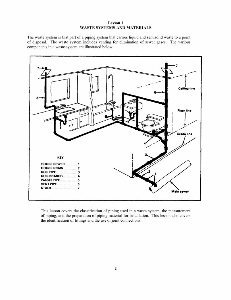
The waste system is that part of a piping system that carries liquid and semisolid waste to a point of disposal. The waste system includes venting for elimination of sewer gases. The various components in a waste system are illustrated below.
This lesson covers the classification of piping used in a waste system, the measurement of piping, and the preparation of piping material for installation. This lesson also covers the identification of fittings and the use of joint connections.
2
Lesson 1/Learning Event 1
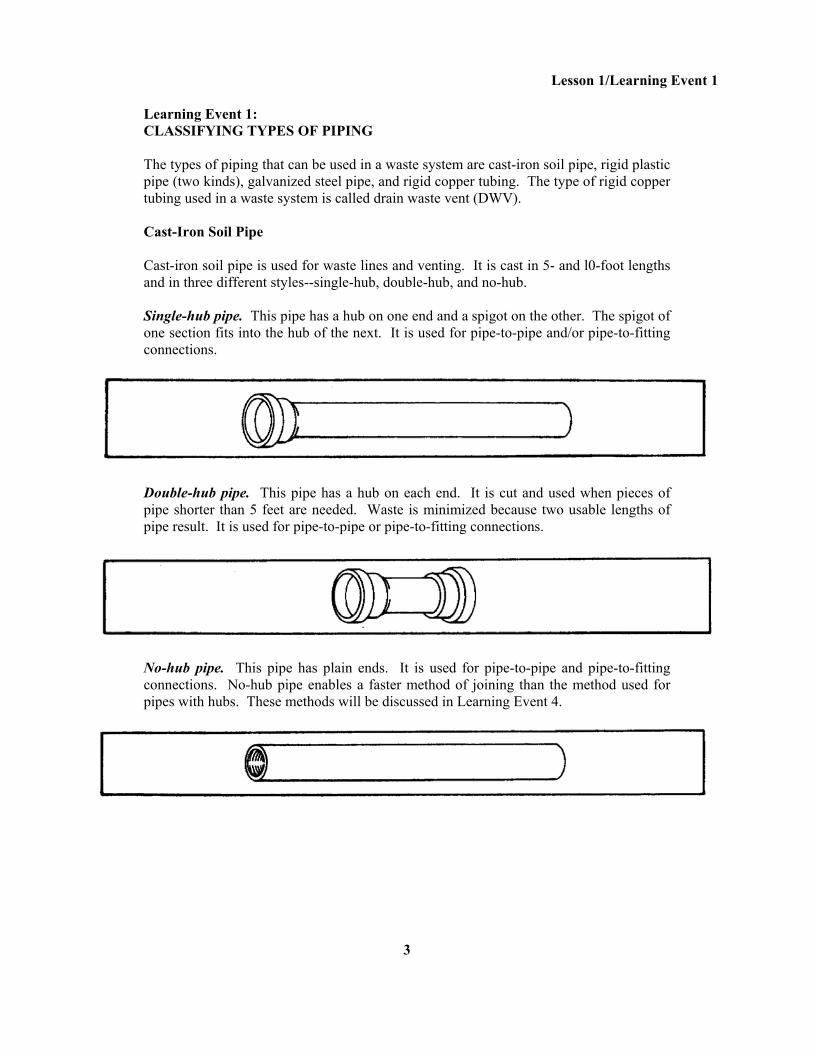
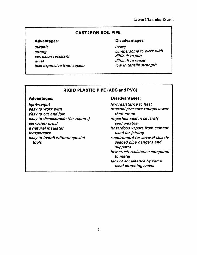
Learning Event 1: CLASSIFYING TYPES OF PIPING The types of piping that can be used in a waste system are cast-iron soil pipe, rigid plastic pipe (two kinds), galvanized steel pipe, and rigid copper tubing. The type of rigid copper tubing used in a waste system is called drain waste vent (DWV). Cast-Iron Soil Pipe Cast-iron soil pipe is used for waste lines and venting. It is cast in 5- and l0-foot lengths and in three different styles--single-hub, double-hub, and no-hub. Single-hub pipe. This pipe has a hub on one end and a spigot on the other. The spigot of one section fits into the hub of the next. It is used for pipe-to-pipe and/or pipe-to-fitting connections.
Double-hub pipe. This pipe has a hub on each end. It is cut and used when pieces of pipe shorter than 5 feet are needed. Waste is minimized because two usable lengths of pipe result. It is used for pipe-to-pipe or pipe-to-fitting connections.
No-hub pipe. This pipe has plain ends. It is used for pipe-to-pipe and pipe-to-fitting connections. No-hub pipe enables a faster method of joining than the method used for pipes with hubs. These methods will be discussed in Learning Event 4.
3
Lesson 1/Learning Event 1
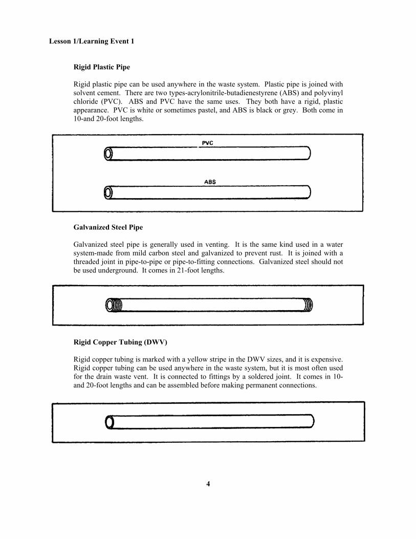
Rigid Plastic Pipe Rigid plastic pipe can be used anywhere in the waste system. Plastic pipe is joined with solvent cement. There are two types-acrylonitrile-butadienestyrene (ABS) and polyvinyl chloride (PVC). ABS and PVC have the same uses. They both have a rigid, plastic appearance. PVC is white or sometimes pastel, and ABS is black or grey. Both come in 10-and 20-foot lengths.
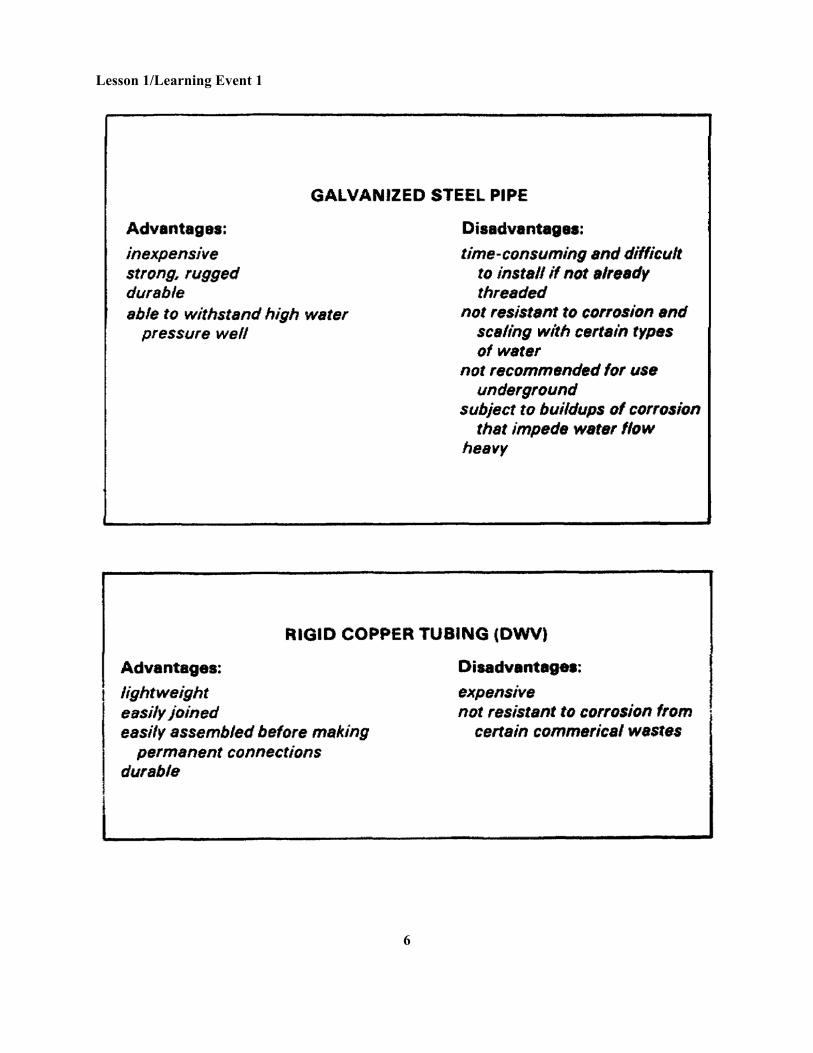
Galvanized Steel Pipe Galvanized steel pipe is generally used in venting. It is the same kind used in a water system-made from mild carbon steel and galvanized to prevent rust. It is joined with a threaded joint in pipe-to-pipe or pipe-to-fitting connections. Galvanized steel should not be used underground. It comes in 21-foot lengths.
Rigid Copper Tubing (DWV) Rigid copper tubing is marked with a yellow stripe in the DWV sizes, and it is expensive. Rigid copper tubing can be used anywhere in the waste system, but it is most often used for the drain waste vent. It is connected to fittings by a soldered joint. It comes in 10-and 20-foot lengths and can be assembled before making permanent connections.
4
Lesson 1/Learning Event 1
5
Lesson 1/Learning Event 1
6
Lesson 1/Learning Event 1
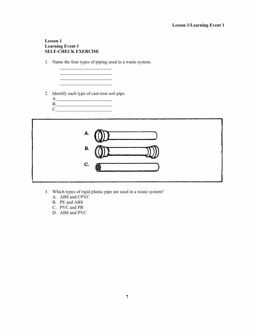
Lesson 1 Learning Event 1 SELF-CHECK EXERCISE 1. Name the four types of piping used in a waste system. 2. Identify each type of cast-iron soil pipe. A. B. C.
3. Which types of rigid plastic pipe are used in a waste system? A. ABS and CPVC B. PE and ABS C. PVC and PB D. ABS and PVC
7
Lesson 1/Learning Event 1 SELF-CHECK EXERCISE SOLUTIONS 1. Cast-iron soil pipe Rigid plastic pipe (ABS and PVC) Galvanized steel pipe Rigid copper tubing Note. Order of listing s not important. 2. A. Single-hub pipe B. Double-hub pipe C. No-hub pipe 3. D. ABS and PVC plastic pipe
If your responses are the same, GREAT. Continue on with the lesson. If not, go back and review the material.
8
Lesson 1/Learning Event 2
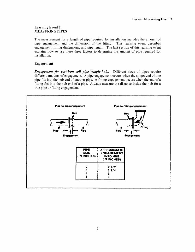
Learning Event 2: MEASURING PIPES The measurement for a length of pipe required for installation includes the amount of pipe engagement and the dimension of the fitting. This learning event describes engagement, fitting dimensions, and pipe length. The last section of this learning event explains how to use these three factors to determine the amount of pipe required for installation. Engagement Engagement for cast-iron soil pipe (single-hub). Different sizes of pipes require different amounts of engagement. A pipe engagement occurs when the spigot end of one pipe fits into the hub end of another pipe. A fitting engagement occurs when the end of a fitting fits into the hub end of a pipe. Always measure the distance inside the hub for a true pipe or fitting engagement.
9
Lesson 1/Learning Event 2
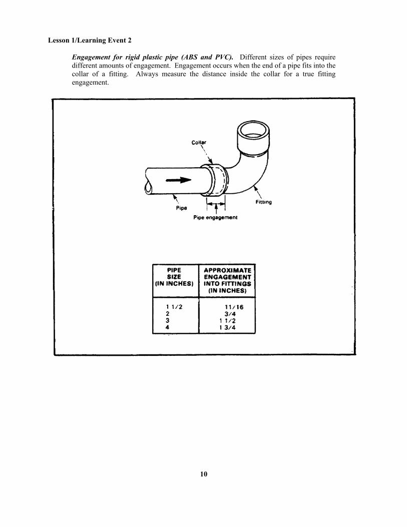
Engagement for rigid plastic pipe (ABS and PVC). Different sizes of pipes require different amounts of engagement. Engagement occurs when the end of a pipe fits into the collar of a fitting. Always measure the distance inside the collar for a true fitting engagement.
10
Lesson 1/Learning Event 2
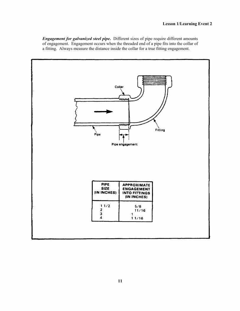
Engagement for galvanized steel pipe. Different sizes of pipe require different amounts of engagement. Engagement occurs when the threaded end of a pipe fits into the collar of a fitting. Always measure the distance inside the collar for a true fitting engagement.
11
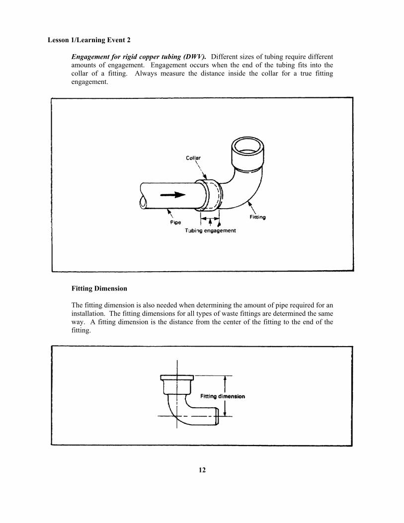
Lesson 1/Learning Event 2 Engagement for rigid copper tubing (DWV). Different sizes of tubing require different amounts of engagement. Engagement occurs when the end of the tubing fits into the collar of a fitting. Always measure the distance inside the collar for a true fitting engagement.
Fitting Dimension The fitting dimension is also needed when determining the amount of pipe required for an installation. The fitting dimensions for all types of waste fittings are determined the same way. A fitting dimension is the distance from the center of the fitting to the end of the fitting.
12
Lesson 1/Learning Event 2
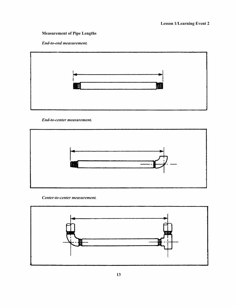
Measurement of Pipe Lengths End-to-end measurement.
End-to-center measurement.
Center-to-center measurement.
13
Lesson 1/Learning Event 2
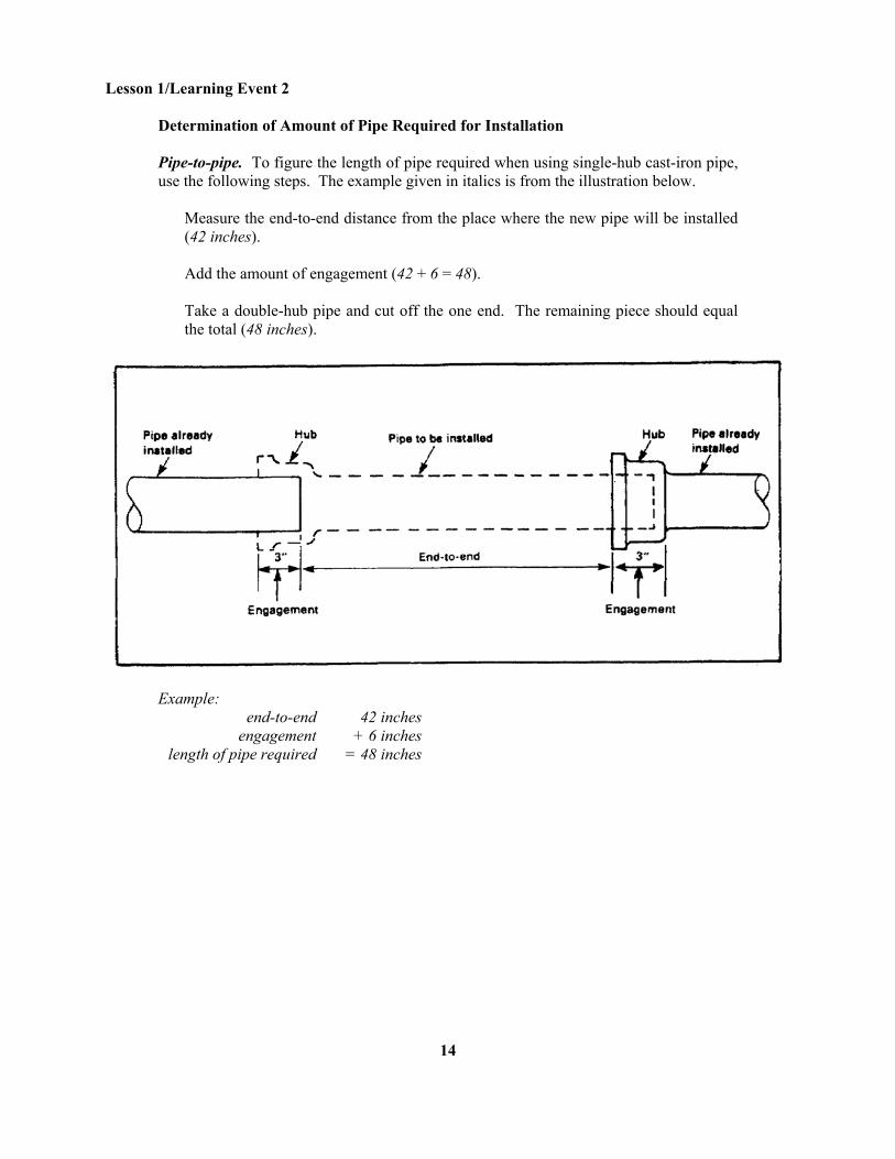
Determination of Amount of Pipe Required for Installation Pipe-to-pipe. To figure the length of pipe required when using single-hub cast-iron pipe, use the following steps. The example given in italics is from the illustration below.
Measure the end-to-end distance from the place where the new pipe will be installed (42 inches). Add the amount of engagement (42 + 6 = 48). Take a double-hub pipe and cut off the one end. The remaining piece should equal the total (48 inches).
Example: end-to-end 42 inches engagement + 6 inches length of pipe required = 48 inches
14
Lesson 1/Learning Event 2
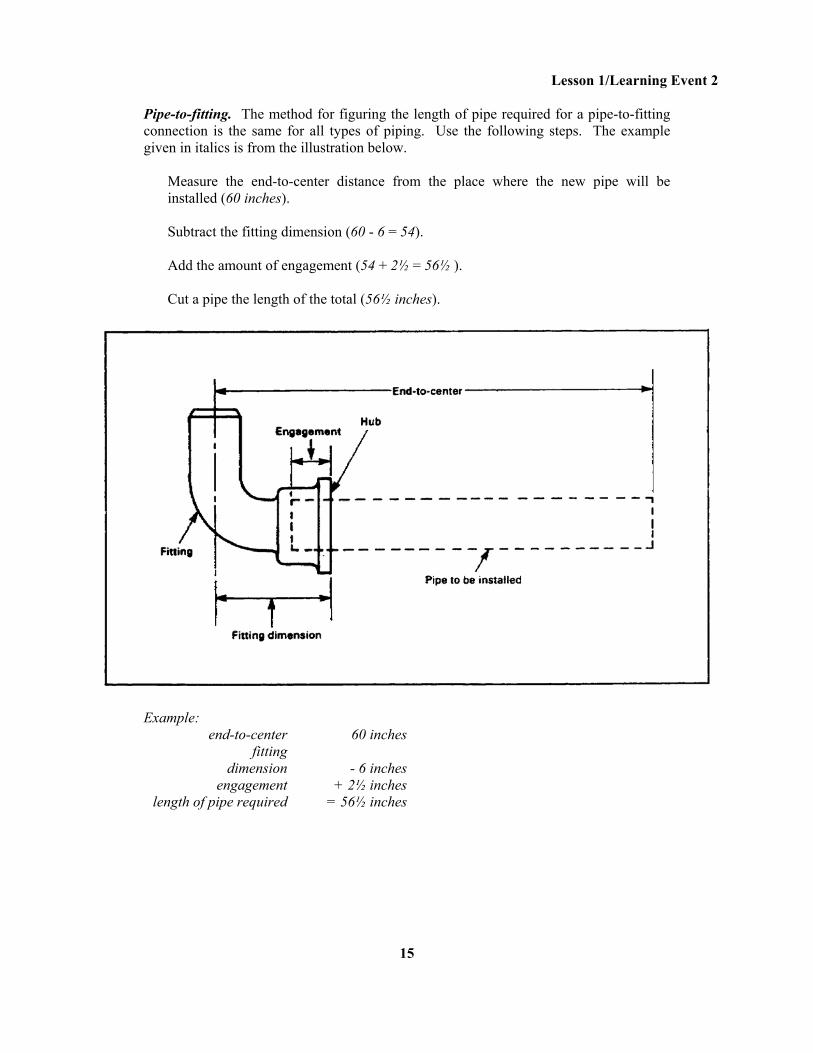
Pipe-to-fitting. The method for figuring the length of pipe required for a pipe-to-fitting connection is the same for all types of piping. Use the following steps. The example given in italics is from the illustration below.
Measure the end-to-center distance from the place where the new pipe will be installed (60 inches). Subtract the fitting dimension (60 - 6 = 54). Add the amount of engagement (54 + 2½ = 56½ ). Cut a pipe the length of the total (56½ inches).
Example: end-to-center 60 inches fitting dimension - 6 inches engagement + 2½ inches length of pipe required = 56½ inches
15
Lesson 1/Learning Event 2
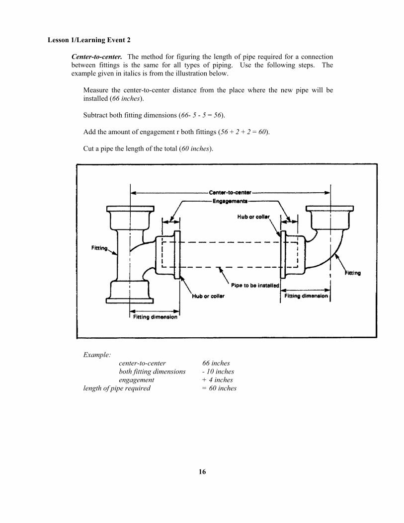
Center-to-center. The method for figuring the length of pipe required for a connection between fittings is the same for all types of piping. Use the following steps. The example given in italics is from the illustration below.
Measure the center-to-center distance from the place where the new pipe will be installed (66 inches). Subtract both fitting dimensions (66- 5 - 5 = 56). Add the amount of engagement r both fittings (56 + 2 + 2 = 60). Cut a pipe the length of the total (60 inches).
Example: center-to-center 66 inches both fitting dimensions - 10 inches engagement + 4 inches length of pipe required = 60 inches
16
Lesson 1/Learning Event 2
Lesson 1 Learning Event 2 SELF-CHECK EXERCISE
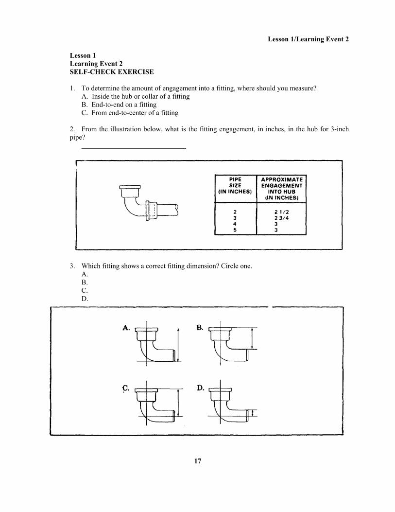
1. To determine the amount of engagement into a fitting, where should you measure? A. Inside the hub or collar of a fitting B. End-to-end on a fitting C. From end-to-center of a fitting 2. From the illustration below, what is the fitting engagement, in inches, in the hub for 3-inch pipe?
3. Which fitting shows a correct fitting dimension? Circle one. A. B. C. D.
17
Lesson 1/Learning Event 2
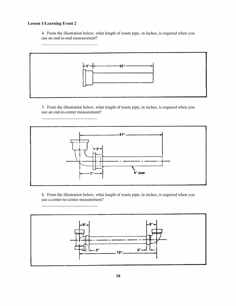
4. From the illustration below, what length of waste pipe, in inches, is required when you use an end-to-end measurement?
5. From the illustration below, what length of waste pipe, in inches, is required when you use an end-to-center measurement?
6. From the illustration below, what length of waste pipe, in inches, is required when you use a center-to-center measurement?
18
Lesson 1/Learning Event 2
SELF-CHECK EXERCISE SOLUTIONS 1. A. Inside the hub or collar of a fitting 2. 2¾ inches 3. C 4. 55 inches End-to-end measurement = 52 inches Engagement into hub = 3 inches Length = 52 + 3 = 55 inches 5. 63 inches End-to-center measurement = 67 inches Fitting dimension = 7 inches Fitting engagement = 3 inches Length = 67 - 7 + 3 = 60 + 3 = 63 inches 6. 64 inches Center-to-center measurement = 72 inches Both fitting dimensions = 6 + 6 =12 inches Both pipe engagements = 2 + 2 = 4 inches Length = 72 -12 + 4 = 60 + 4 = 64 inches If your responses are the same, GREAT. Continue on with the lesson. If not, go back and review the material.
19
Lesson 1/Learning Event 3
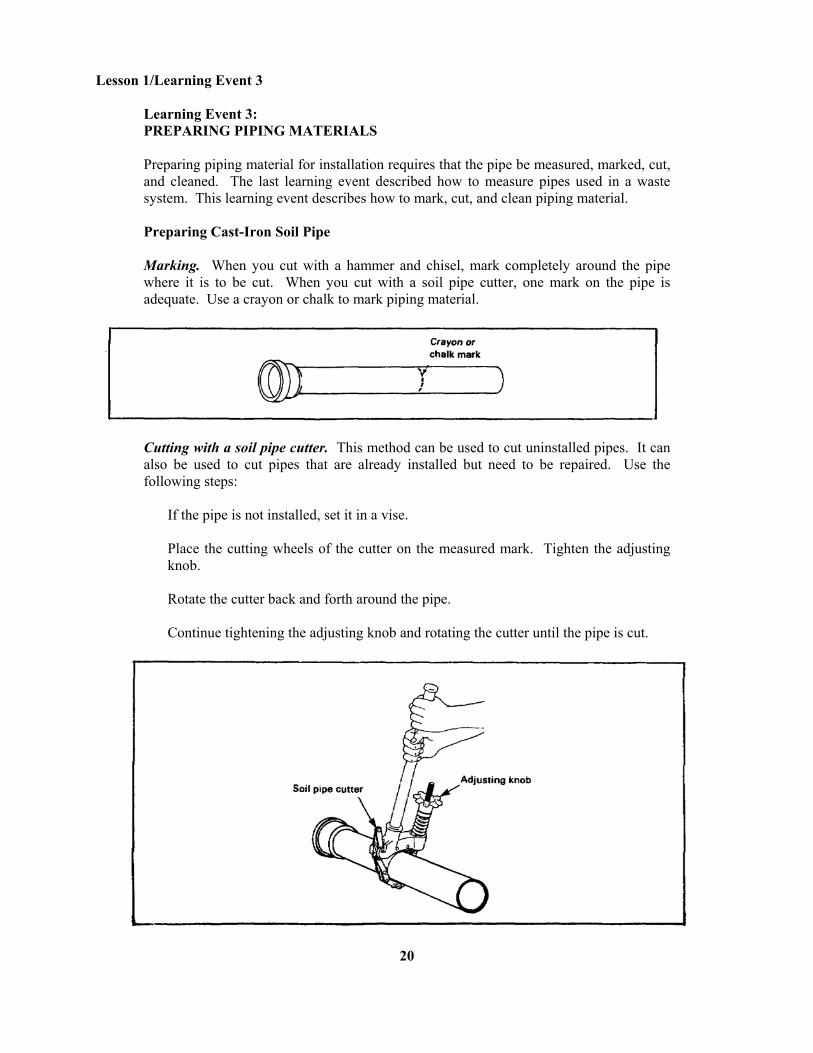
Learning Event 3: PREPARING PIPING MATERIALS Preparing piping material for installation requires that the pipe be measured, marked, cut, and cleaned. The last learning event described how to measure pipes used in a waste system. This learning event describes how to mark, cut, and clean piping material. Preparing Cast-Iron Soil Pipe Marking. When you cut with a hammer and chisel, mark completely around the pipe where it is to be cut. When you cut with a soil pipe cutter, one mark on the pipe is adequate. Use a crayon or chalk to mark piping material.
Cutting with a soil pipe cutter. This method can be used to cut uninstalled pipes. It can also be used to cut pipes that are already installed but need to be repaired. Use the following steps:
If the pipe is not installed, set it in a vise. Place the cutting wheels of the cutter on the measured mark. Tighten the adjusting knob. Rotate the cutter back and forth around the pipe. Continue tightening the adjusting knob and rotating the cutter until the pipe is cut.
20
Lesson 1/Learning Event 3
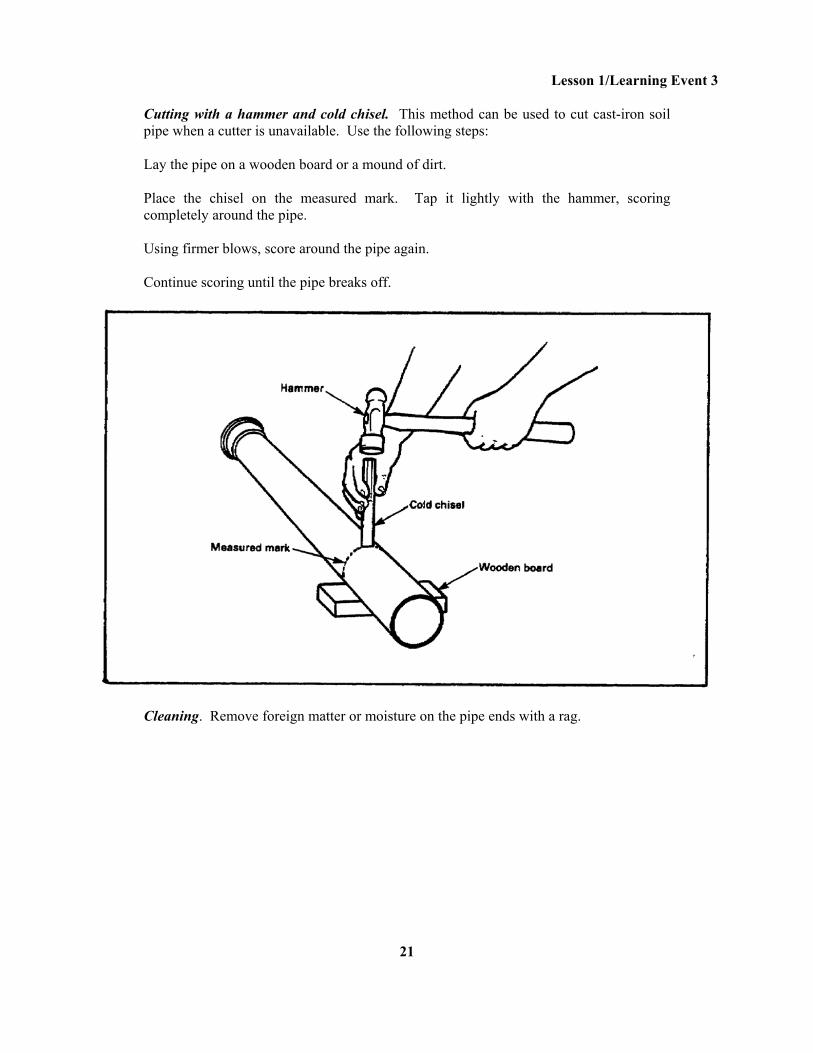
Cutting with a hammer and cold chisel. This method can be used to cut cast-iron soil pipe when a cutter is unavailable. Use the following steps: Lay the pipe on a wooden board or a mound of dirt. Place the chisel on the measured mark. Tap it lightly with the hammer, scoring completely around the pipe. Using firmer blows, score around the pipe again. Continue scoring until the pipe breaks off.
Cleaning. Remove foreign matter or moisture on the pipe ends with a rag.
21
Lesson 1/Learning Event 3
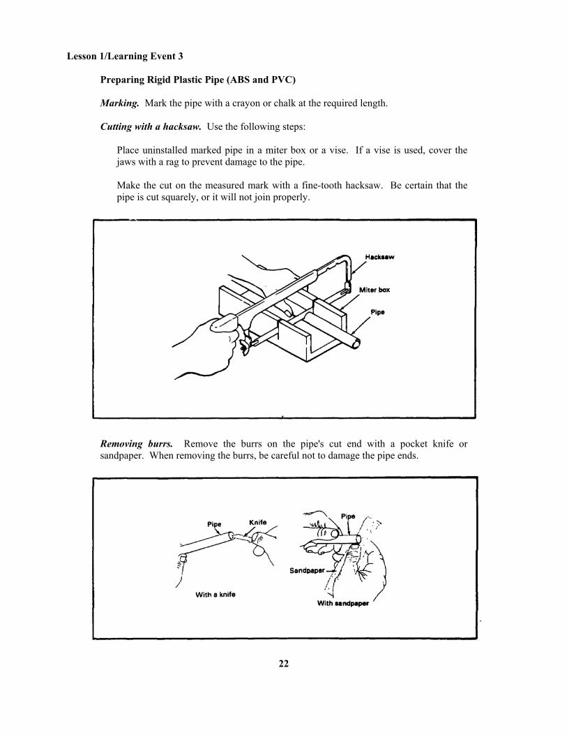
Preparing Rigid Plastic Pipe (ABS and PVC) Marking. Mark the pipe with a crayon or chalk at the required length. Cutting with a hacksaw. Use the following steps:
Place uninstalled marked pipe in a miter box or a vise. If a vise is used, cover the jaws with a rag to prevent damage to the pipe. Make the cut on the measured mark with a fine-tooth hacksaw. Be certain that the pipe is cut squarely, or it will not join properly.
Removing burrs. Remove the burrs on the pipe's cut end with a pocket knife or sandpaper. When removing the burrs, be careful not to damage the pipe ends.
22
Lesson 1/Learning Event 3
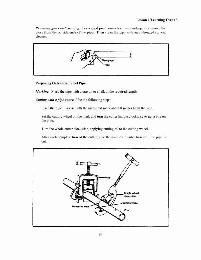
Removing gloss and cleaning. For a good joint connection, use sandpaper to remove the gloss from the outside ends of the pipe. Then clean the pipe with an authorized solvent cleaner.
Preparing Galvanized Steel Pipe Marking. Mark the pipe with a crayon or chalk at the required length. Cutting with a pipe cutter. Use the following steps:
Place the pipe in a vise with the measured mark about 8 inches from the vise. Set the cutting wheel on the mark and turn the cutter handle clockwise to get a bite on the pipe. Turn the whole cutter clockwise, applying cutting oil to the cutting wheel. After each complete turn of the cutter, give the handle a quarter turn until the pipe is cut.
23
Lesson 1/Learning Event 3
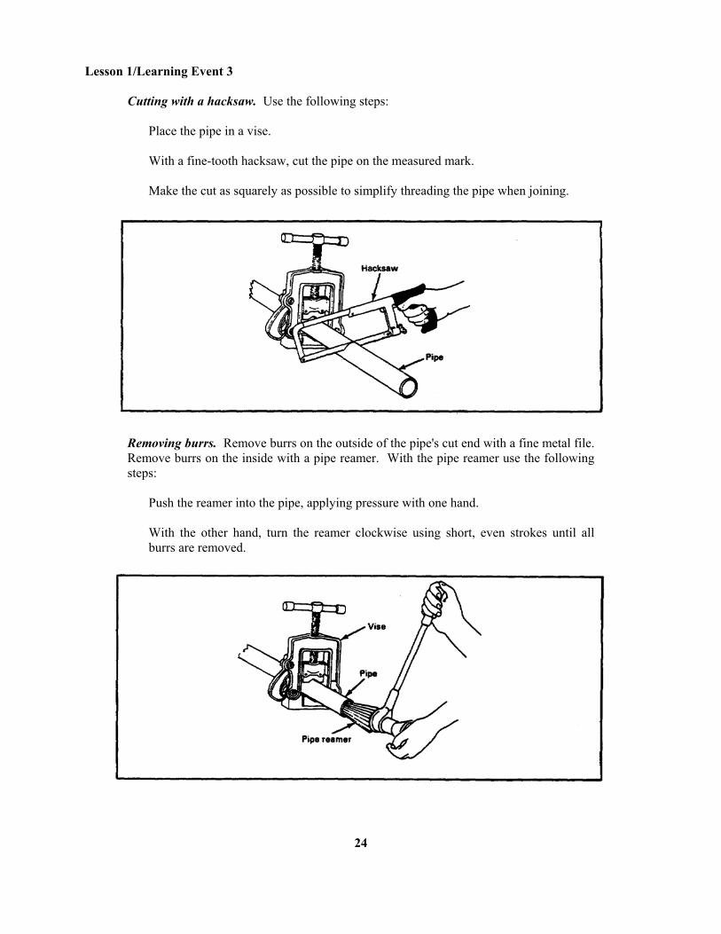
Cutting with a hacksaw. Use the following steps:
Place the pipe in a vise. With a fine-tooth hacksaw, cut the pipe on the measured mark. Make the cut as squarely as possible to simplify threading the pipe when joining.
Removing burrs. Remove burrs on the outside of the pipe's cut end with a fine metal file. Remove burrs on the inside with a pipe reamer. With the pipe reamer use the following steps:
Push the reamer into the pipe, applying pressure with one hand. With the other hand, turn the reamer clockwise using short, even strokes until all burrs are removed.
24
Lesson 1/Learning Event 3
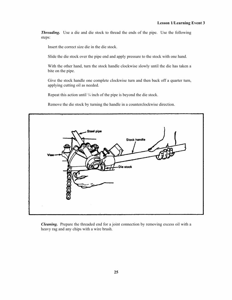
Threading. Use a die and die stock to thread the ends of the pipe. Use the following steps:
Insert the correct size die in the die stock. Slide the die stock over the pipe end and apply pressure to the stock with one hand. With the other hand, turn the stock handle clockwise slowly until the die has taken a bite on the pipe. Give the stock handle one complete clockwise turn and then back off a quarter turn, applying cutting oil as needed. Repeat this action until ¼ inch of the pipe is beyond the die stock. Remove the die stock by turning the handle in a counterclockwise direction.
Cleaning. Prepare the threaded end for a joint connection by removing excess oil with a heavy rag and any chips with a wire brush.
25
Lesson 1/Learning Event 3
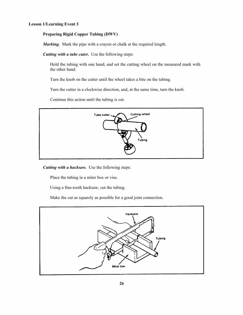
Preparing Rigid Copper Tubing (DWV) Marking. Mark the pipe with a crayon or chalk at the required length. Cutting with a tube cuter. Use the following steps:
Hold the tubing with one hand, and set the cutting wheel on the measured mark with the other hand. Turn the knob on the cutter until the wheel takes a bite on the tubing. Turn the cutter in a clockwise direction, and, at the same time, turn the knob. Continue this action until the tubing is cut.
Cutting with a hacksaw. Use the following steps:
Place the tubing in a miter box or vise. Using a fine-tooth hacksaw, cut the tubing. Make the cut as squarely as possible for a good joint connection.
26
Lesson 1 /Learning Event 3
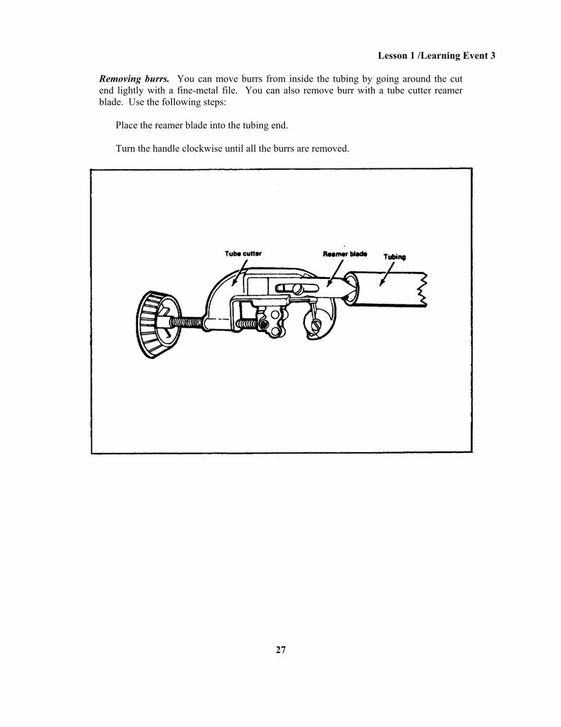
Removing burrs. You can move burrs from inside the tubing by going around the cut end lightly with a fine-metal file. You can also remove burr with a tube cutter reamer blade. Use the following steps:
Place the reamer blade into the tubing end. Turn the handle clockwise until all the burrs are removed.
27
Lesson 1/Learning Event 3
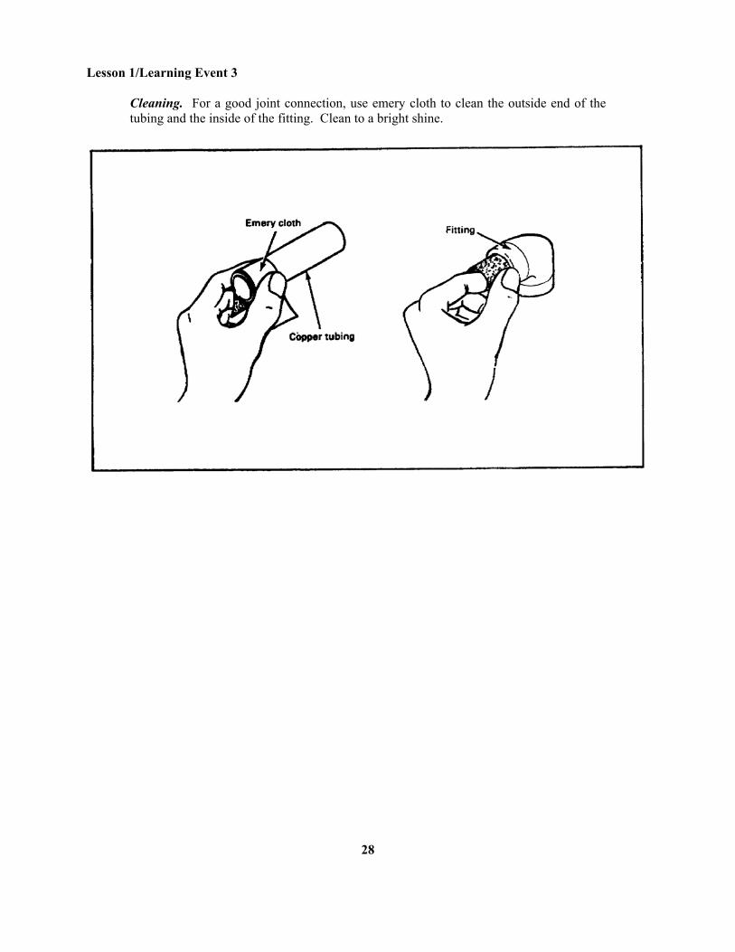
Cleaning. For a good joint connection, use emery cloth to clean the outside end of the tubing and the inside of the fitting. Clean to a bright shine.
28
Lesson 1/Learning Event 3 Lesson 1 Learning Event 3 SELF-CHECK EXERCISE Fill in the blanks. Cast-iron soil pipe: 1. You are to cut a cast-iron so pipe with a hammer and chisel. Once you have measured the pipe length required, the length is marked with crayon or chalk. 2. When you are scoring cast-iron pipe by tapping a cold chisel with a hammer, the score is made completely the pipe. 3. When you are cutting cast-iron pipe with a soil pipe cutter, the cutter is rotated and around the pipe until it is cut. 4. As you rotate the cutter, tighten the until the pipe is cut. Rigid plastic pipe (ABS and PVC): 5. Rigid plastic pipe (ABS and PVC) is cut with a . 6. The burrs from the cut end of plastic pipe can be removed with a or . 7. The from an outside end of plastic pipe is removed with . Galvanized steel pipe: 8. To cut galvanized steel pipe with a single-wheel pipe cutter, the cutting wheel is placed on the . 9. For every one complete turn around the pipe with the pipe cutter, the cutter's handle is given an additional . 10. Galvanized steel pipe can also be cut with a . 11. The burrs from the inside of the cut end of the pipe are removed with a . 12. A completely threaded steel pipe should extend inch(es) beyond the die stock. Rigid copper tubing (DWV): 13. Rigid copper tubing (DWV) can be cut with a or a . 14. The buns from the cut end can be removed with a or a . 15. The outside cut end of rigid copper tubing (DWV) is cleaned to a bright shine with .
29
Lesson 1/Learning Event 3
SELF-CHECK EXERCISE SOLUTIONS 1. Around the pipe 2. Around 3. Back and forth 4. Adjusting knob 5. Hacksaw with fine-tooth blade 6. Knife, sandpaper 7. Gloss, sandpaper 8. Measured mark 9. Quarter turn 10. Hacksaw 11. Pipe reamer 12. ¼ inch 13. Tube cutter, hacksaw 14. Reamer blade, metal file 15. Emery cloth If your responses are the same, GREAT. Continue on with the lesson. If not, go back and review the material.
30
Lesson 1/Learning Event 4
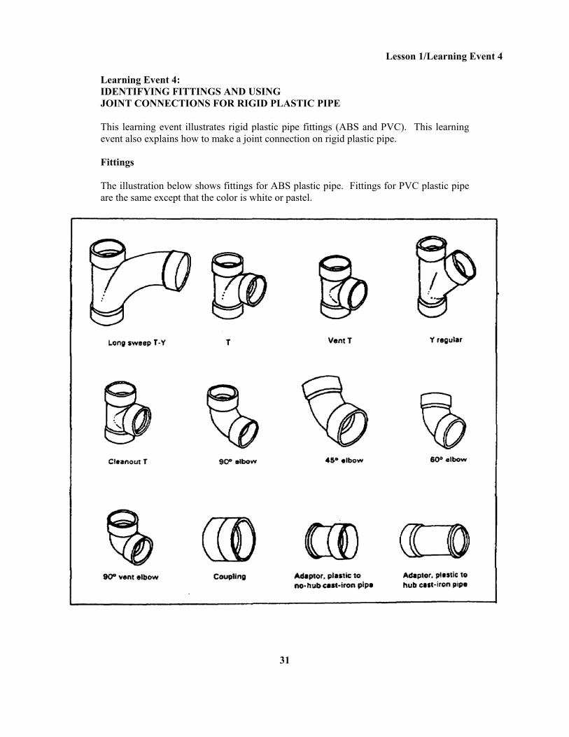
Learning Event 4: IDENTIFYING FITTINGS AND USING JOINT CONNECTIONS FOR RIGID PLASTIC PIPE This learning event illustrates rigid plastic pipe fittings (ABS and PVC). This learning event also explains how to make a joint connection on rigid plastic pipe. Fittings The illustration below shows fittings for ABS plastic pipe. Fittings for PVC plastic pipe are the same except that the color is white or pastel.
31
Lesson 1/Learning Event 4
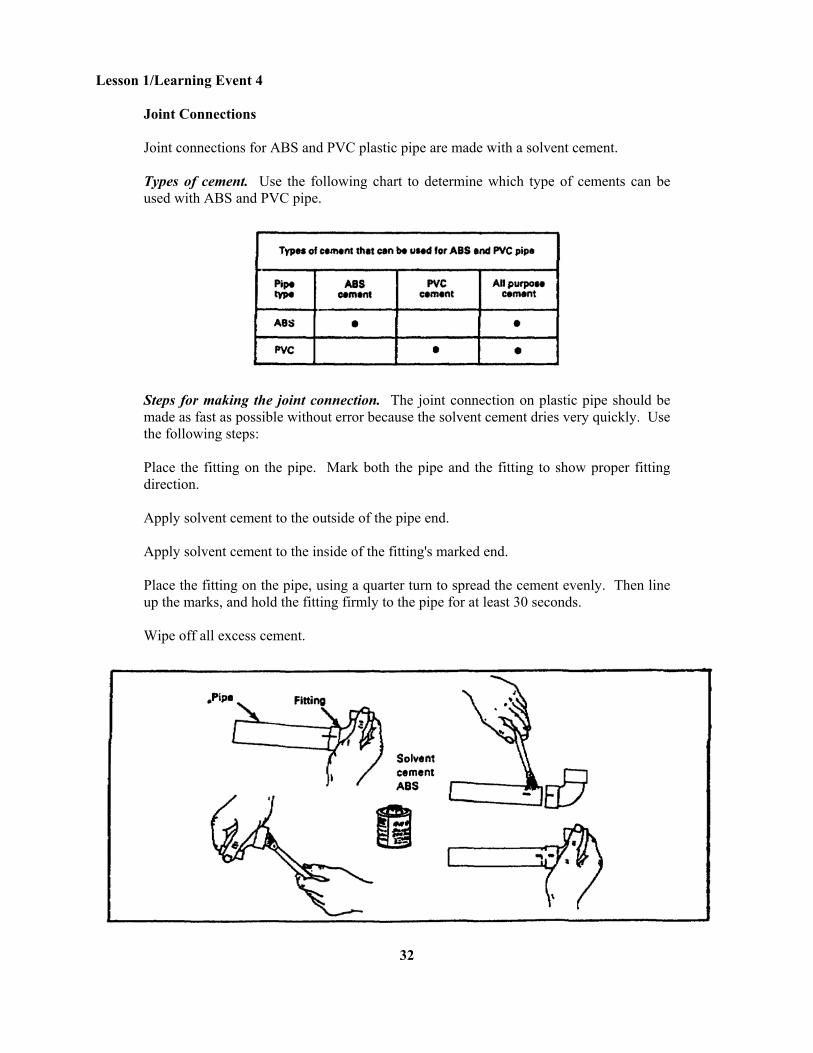
Joint Connections Joint connections for ABS and PVC plastic pipe are made with a solvent cement. Types of cement. Use the following chart to determine which type of cements can be used with ABS and PVC pipe.
Steps for making the joint connection. The joint connection on plastic pipe should be made as fast as possible without error because the solvent cement dries very quickly. Use the following steps: Place the fitting on the pipe. Mark both the pipe and the fitting to show proper fitting direction. Apply solvent cement to the outside of the pipe end. Apply solvent cement to the inside of the fitting's marked end. Place the fitting on the pipe, using a quarter turn to spread the cement evenly. Then line up the marks, and hold the fitting firmly to the pipe for at least 30 seconds. Wipe off all excess cement.
32
Lesson 1/Learning Event 4
Lesson 1 Learning Event 4 SELF-CHECK EXERCISE
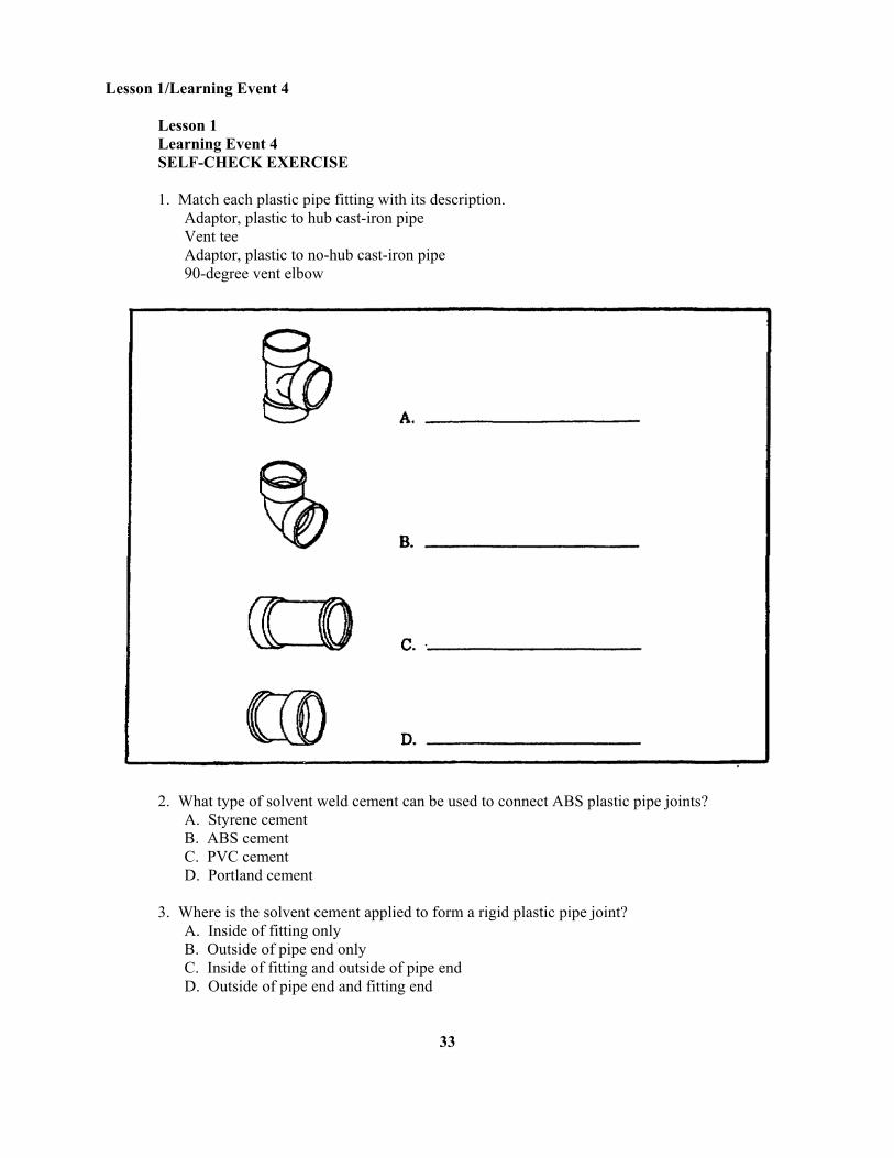
1. Match each plastic pipe fitting with its description. Adaptor, plastic to hub cast-iron pipe Vent tee Adaptor, plastic to no-hub cast-iron pipe 90-degree vent elbow
2. What type of solvent weld cement can be used to connect ABS plastic pipe joints? A. Styrene cement B. ABS cement C. PVC cement D. Portland cement 3. Where is the solvent cement applied to form a rigid plastic pipe joint? A. Inside of fitting only B. Outside of pipe end only C. Inside of fitting and outside of pipe end D. Outside of pipe end and fitting end
33
Lesson 1 /Learning Event 4
SELF-CHECK EXERCISE SOLUTIONS 1. A. Vent tee B. 90-degree vent elbow C. Adaptor, plastic to hub cast-iron pipe D. Adaptor, plastic to no-hub cast-iron pipe 2. B. ABS cement can be used for ABS plastic pipe 3. C. Solvent cement is applied to the outside of pipe end and to inside of fitting end to be attached. If your responses are the same, GREAT. Continue on with the lesson. If not, go back and review the material.
34
Lesson 1 /Learning Event 5
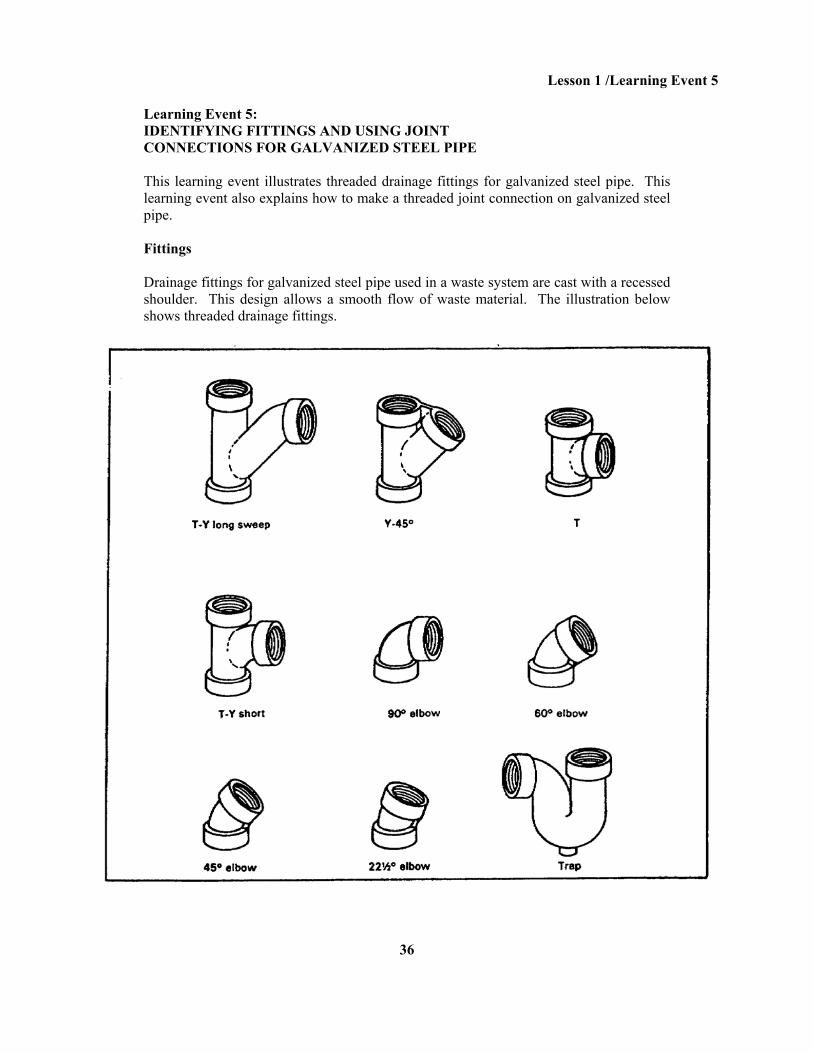
Learning Event 5: IDENTIFYING FITTINGS AND USING JOINT CONNECTIONS FOR GALVANIZED STEEL PIPE This learning event illustrates threaded drainage fittings for galvanized steel pipe. This learning event also explains how to make a threaded joint connection on galvanized steel pipe. Fittings Drainage fittings for galvanized steel pipe used in a waste system are cast with a recessed shoulder. This design allows a smooth flow of waste material. The illustration below shows threaded drainage fittings.
36
Lesson 1/Learning Event 5
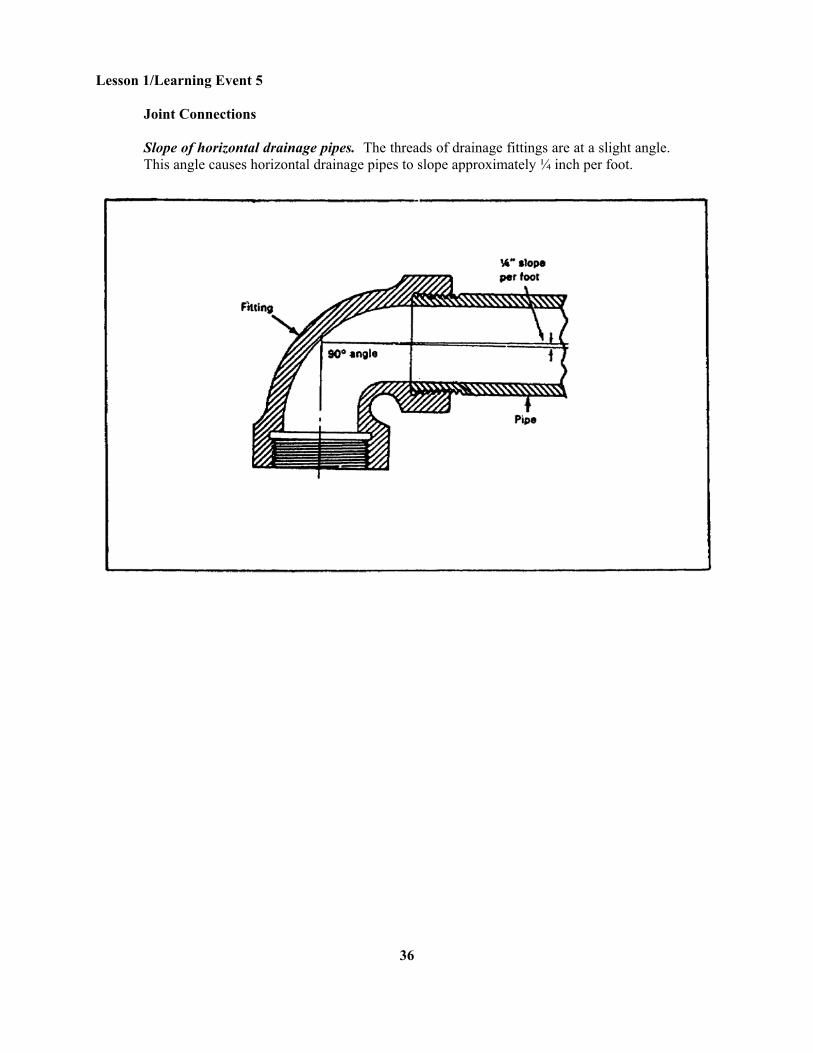
Joint Connections Slope of horizontal drainage pipes. The threads of drainage fittings are at a slight angle. This angle causes horizontal drainage pipes to slope approximately ¼ inch per foot.
36
Lesson 1 /Learning Event 5
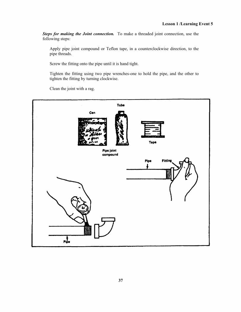
Steps for making the Joint connection. To make a threaded joint connection, use the following steps:
Apply pipe joint compound or Teflon tape, in a counterclockwise direction, to the pipe threads. Screw the fitting onto the pipe until it is hand tight. Tighten the fitting using two pipe wrenches-one to hold the pipe, and the other to tighten the fitting by turning clockwise. Clean the joint with a rag.
37
Lesson 1/Learning Event 5
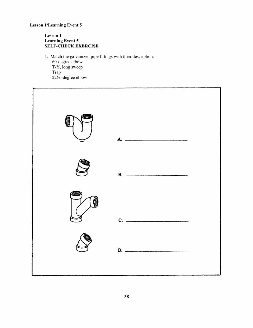
Lesson 1 Learning Event 5 SELF-CHECK EXERCISE 1. Match the galvanized pipe fittings with their description. 60-degree elbow T-Y, long sweep Trap 22½ -degree elbow
38
Lesson 1/Learning Event 5
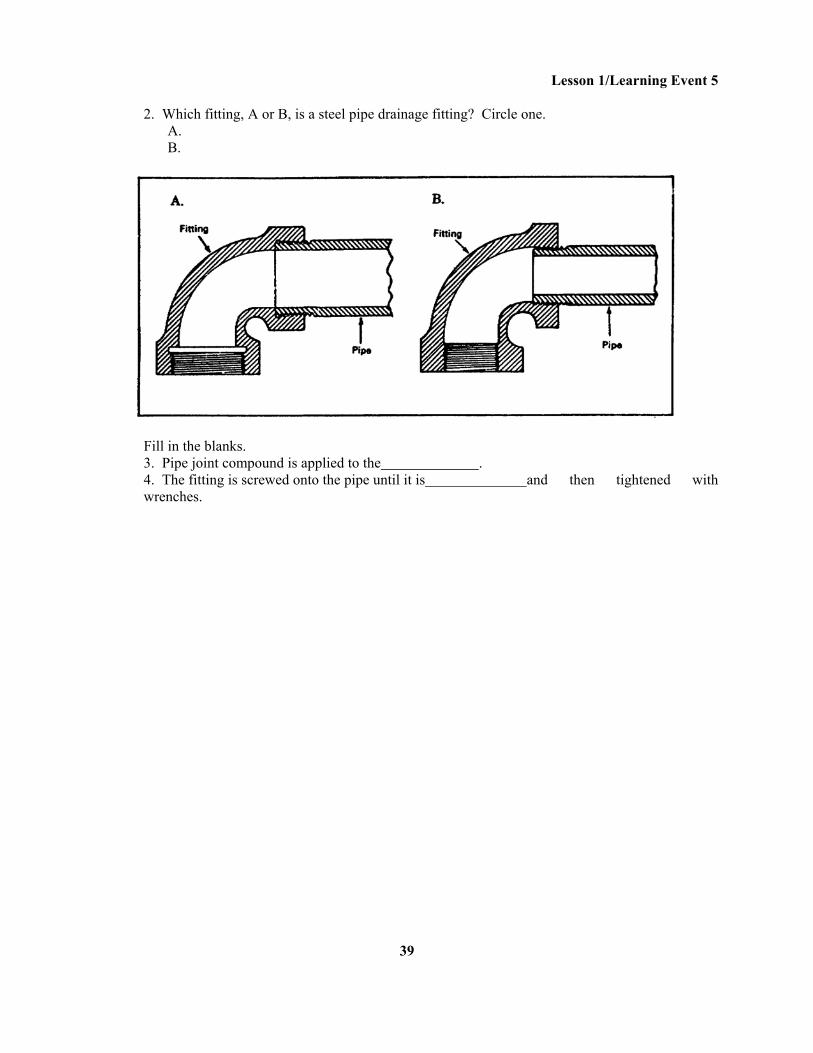
2. Which fitting, A or B, is a steel pipe drainage fitting? Circle one. A. B.
Fill in the blanks. 3. Pipe joint compound is applied to the . 4. The fitting is screwed onto the pipe until it is and then tightened with wrenches.
39
Lesson 1 /Learning Event 5
SELF-CHECK EXERCISE SOLUTIONS 1. A. Trap B. 22 ½-degree elbow C. T-Y, long sweep D. 60-degree elbow 2. A 3. Pipe thread 4. Hand tight If your responses are the same, GREAT. Continue on with the lesson. If not, go back hand review the material.
40
Lesson 1/Learning Event 6
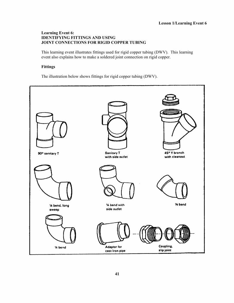
Learning Event 6: IDENTIFYING FITTINGS AND USING JOINT CONNECTIONS FOR RIGID COPPER TUBING This learning event illustrates fittings used for rigid copper tubing (DWV). This learning event also explains how to make a soldered joint connection on rigid copper. Fittings The illustration below shows fittings for rigid copper tubing (DWV).
41
Lesson 1/Learning Event 6
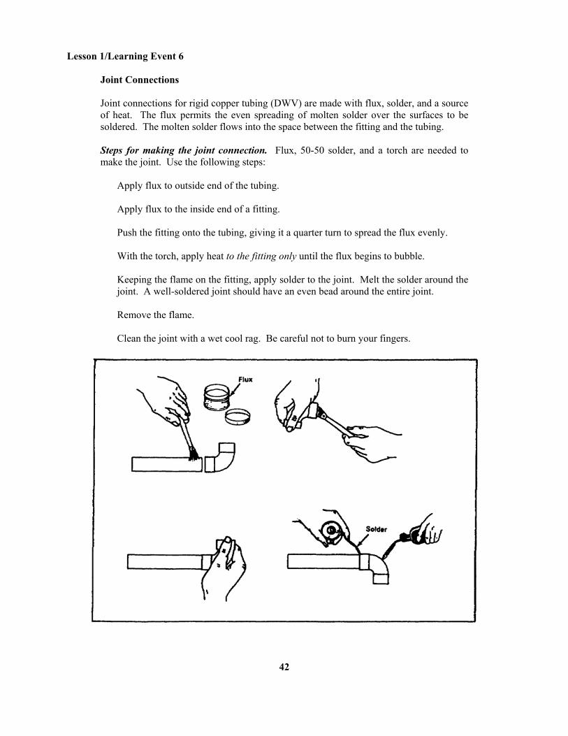
Joint Connections Joint connections for rigid copper tubing (DWV) are made with flux, solder, and a source of heat. The flux permits the even spreading of molten solder over the surfaces to be soldered. The molten solder flows into the space between the fitting and the tubing. Steps for making the joint connection. Flux, 50-50 solder, and a torch are needed to make the joint. Use the following steps:
Apply flux to outside end of the tubing. Apply flux to the inside end of a fitting. Push the fitting onto the tubing, giving it a quarter turn to spread the flux evenly. With the torch, apply heat to the fitting only until the flux begins to bubble. Keeping the flame on the fitting, apply solder to the joint. Melt the solder around the joint. A well-soldered joint should have an even bead around the entire joint. Remove the flame. Clean the joint with a wet cool rag. Be careful not to burn your fingers.
42
Lesson 1/Learning Event 6
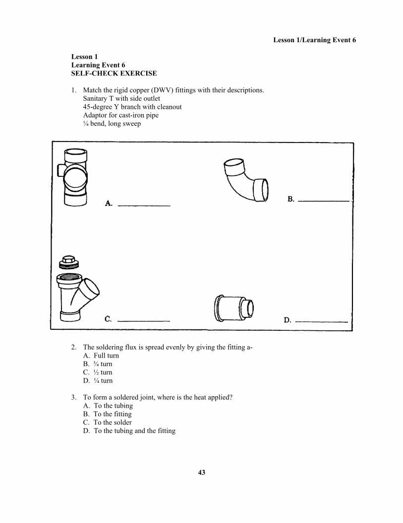
Lesson 1 Learning Event 6 SELF-CHECK EXERCISE 1. Match the rigid copper (DWV) fittings with their descriptions. Sanitary T with side outlet 45-degree Y branch with cleanout Adaptor for cast-iron pipe ¼ bend, long sweep
2. The soldering flux is spread evenly by giving the fitting a- A. Full turn B. ¾ turn C. ½ turn D. ¼ turn 3. To form a soldered joint, where is the heat applied? A. To the tubing B. To the fitting C. To the solder D. To the tubing and the fitting
43
Lesson 1/Learning Event 6
SELF-CHECK EXERCISE SOLUTIONS 1. A. Sanitary T with side outlet B. ¼ bend, long sweep C. 45-degree Y branch with cleanout D. Adaptor for cast-iron pipe 2. D. The fitting is given a ¼ turn to spread the soldering flux evenly. 3. B. Heat only the fitting. If your responses are the same, GREAT. Continue on with the Review Exercise. If not, go back and review the material.
44
Lesson 1/Review Exercise
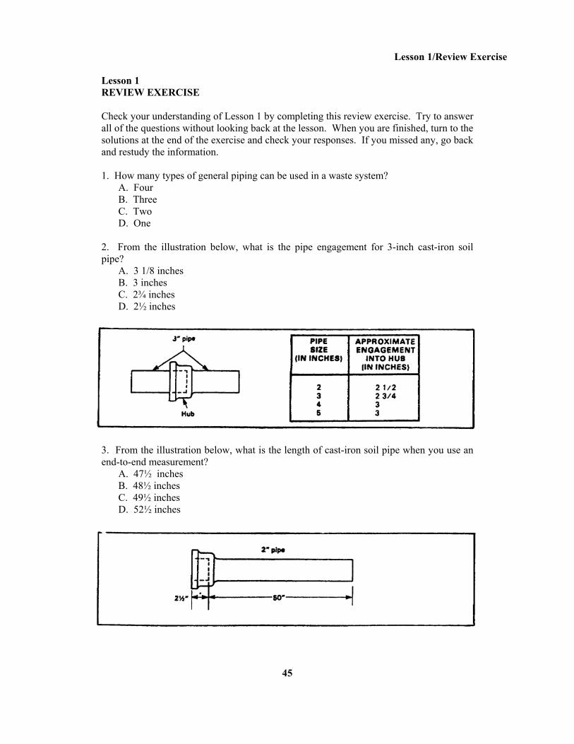
Lesson 1 REVIEW EXERCISE Check your understanding of Lesson 1 by completing this review exercise. Try to answer all of the questions without looking back at the lesson. When you are finished, turn to the solutions at the end of the exercise and check your responses. If you missed any, go back and restudy the information. 1. How many types of general piping can be used in a waste system? A. Four B. Three C. Two D. One 2. From the illustration below, what is the pipe engagement for 3-inch cast-iron soil pipe? A. 3 1/8 inches B. 3 inches C. 2¾ inches D. 2½ inches
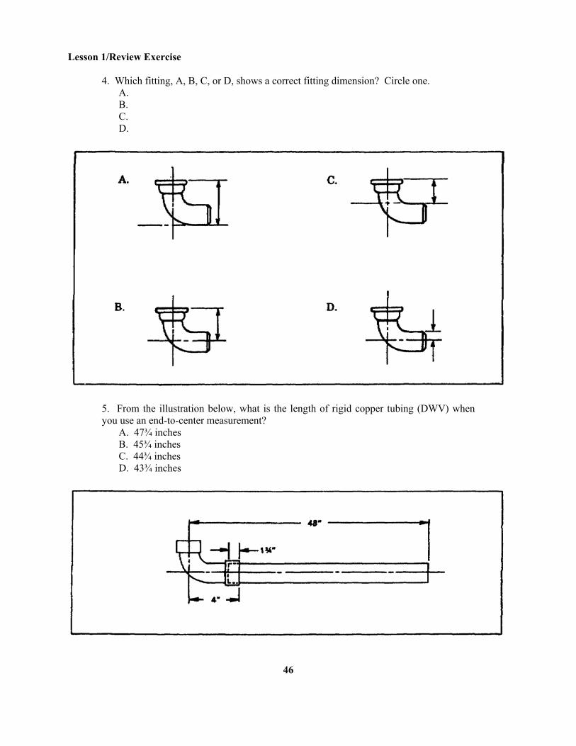
3. From the illustration below, what is the length of cast-iron soil pipe when you use an end-to-end measurement? A. 47½ inches B. 48½ inches C. 49½ inches D. 52½ inches
45
Lesson 1/Review Exercise
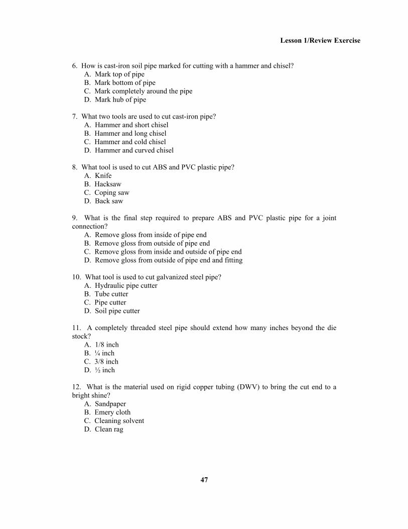
4. Which fitting, A, B, C, or D, shows a correct fitting dimension? Circle one. A. B. C. D.
5. From the illustration below, what is the length of rigid copper tubing (DWV) when you use an end-to-center measurement? A. 47¾ inches B. 45¾ inches C. 44¾ inches D. 43¾ inches
46
Lesson 1/Review Exercise
6. How is cast-iron soil pipe marked for cutting with a hammer and chisel? A. Mark top of pipe B. Mark bottom of pipe C. Mark completely around the pipe D. Mark hub of pipe 7. What two tools are used to cut cast-iron pipe? A. Hammer and short chisel B. Hammer and long chisel C. Hammer and cold chisel D. Hammer and curved chisel 8. What tool is used to cut ABS and PVC plastic pipe? A. Knife B. Hacksaw C. Coping saw D. Back saw 9. What is the final step required to prepare ABS and PVC plastic pipe for a joint connection? A. Remove gloss from inside of pipe end B. Remove gloss from outside of pipe end C. Remove gloss from inside and outside of pipe end D. Remove gloss from outside of pipe end and fitting 10. What tool is used to cut galvanized steel pipe? A. Hydraulic pipe cutter B. Tube cutter C. Pipe cutter D. Soil pipe cutter 11. A completely threaded steel pipe should extend how many inches beyond the die stock? A. 1/8 inch B. ¼ inch C. 3/8 inch D. ½ inch 12. What is the material used on rigid copper tubing (DWV) to bring the cut end to a bright shine? A. Sandpaper B. Emery cloth C. Cleaning solvent D. Clean rag
47
Lesson 1/Review Exercise
13. What is used to connect no-hub cast-iron soil pipe? A. Clamp B. Coupling C. Coupling and clamp D. Coupling and cement 14. What type of solvent weld cement is needed to connect ABS and PVC rigid plastic pipe? A. ABS cement B. Styrene cement C. Portland cement D. All purpose cement 15. Where is the solvent weld cement applied to form a joint for rigid plastic pipe? A. Outside ends of pipe and fitting B. Outside end of pipe only C. Outside end of pipe and inside end of fitting D. Inside end of fitting only 16. Where is the heat applied to make a soldered joint for rigid copper tubing (DWV) ? A. Pipe B. Flux C. Fitting D. Solder 17. Where is the joint compound applied for a threaded drainage fitting joint for steel pipe? A. Fitting threads only B. Pipe threads only C. Pipe and fitting threads D. All threads
48

Lesson 1/ Review Exercise
THIS PAGE INTENTIONALLY LEFT BLANK.
49
Lesson 1/Review Exercise
REVIEW EXERCISE SOLUTIONS 1. A (Page 3) 2. C (Page 9) 3. D (Page 14) 4. B (Page 13) 5. B (Page 15) 6. C (Page 20) 7. C (Page 21) 8. B (Page 22) 9. B (Page 23) 10. C (Page 23) 11. B (Page 25) 12. B (Page 28) 13. C (Page 3) 14. D (Page 32) 15. C (Page 32) 16. C (Page 42) 17. B (Page 37)
50
Lesson 2 WASTE SYSTEM ROUGHING-IN
OBJECTIVE At the end of this lesson, you will be able to describe the procedures for installing cast-iron pipe for a rough-in waste system. TASK Task 051-248-1003, Install cast-iron pipe. CONDITIONS You will have subcourse booklet EN5112. You will work at your own pace and in your own selected environment with no supervision. STANDARDS Within approximately 8 hours, you will be able to study the lesson resources, answer the practice exercise questions, and select the correct response for each examination question. You must respond correctly to 70 percent of the examination questions in order to receive credit for the subcourse. REFERENCES FM 5-51K1/2 TM 5-551K
51
Lesson 2 WASTE SYSTEM ROUGHING-IN
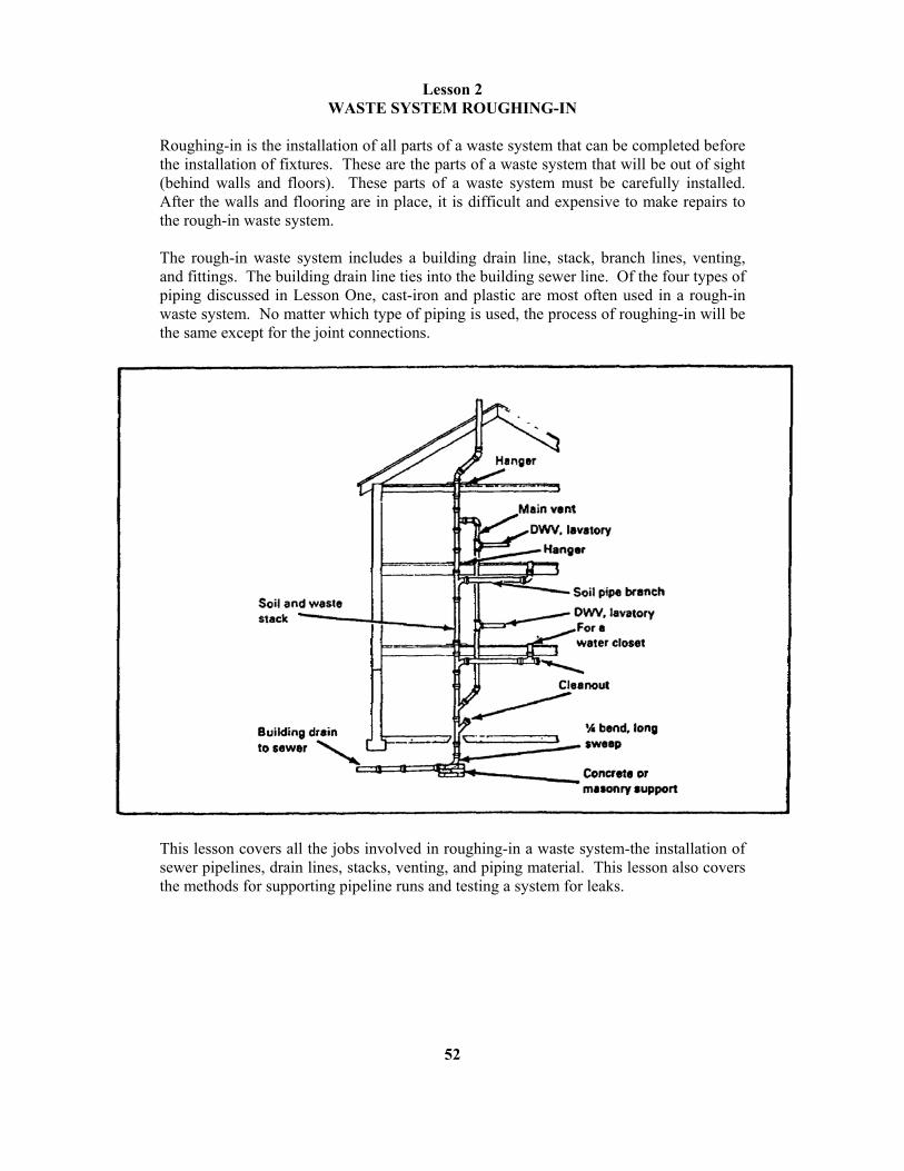
Roughing-in is the installation of all parts of a waste system that can be completed before the installation of fixtures. These are the parts of a waste system that will be out of sight (behind walls and floors). These parts of a waste system must be carefully installed. After the walls and flooring are in place, it is difficult and expensive to make repairs to the rough-in waste system. The rough-in waste system includes a building drain line, stack, branch lines, venting, and fittings. The building drain line ties into the building sewer line. Of the four types of piping discussed in Lesson One, cast-iron and plastic are most often used in a rough-in waste system. No matter which type of piping is used, the process of roughing-in will be the same except for the joint connections.
This lesson covers all the jobs involved in roughing-in a waste system-the installation of sewer pipelines, drain lines, stacks, venting, and piping material. This lesson also covers the methods for supporting pipeline runs and testing a system for leaks.
52
Lesson 2/Learning Event 1 Learning Event 1: INSTALLING SEWER PIPELINES
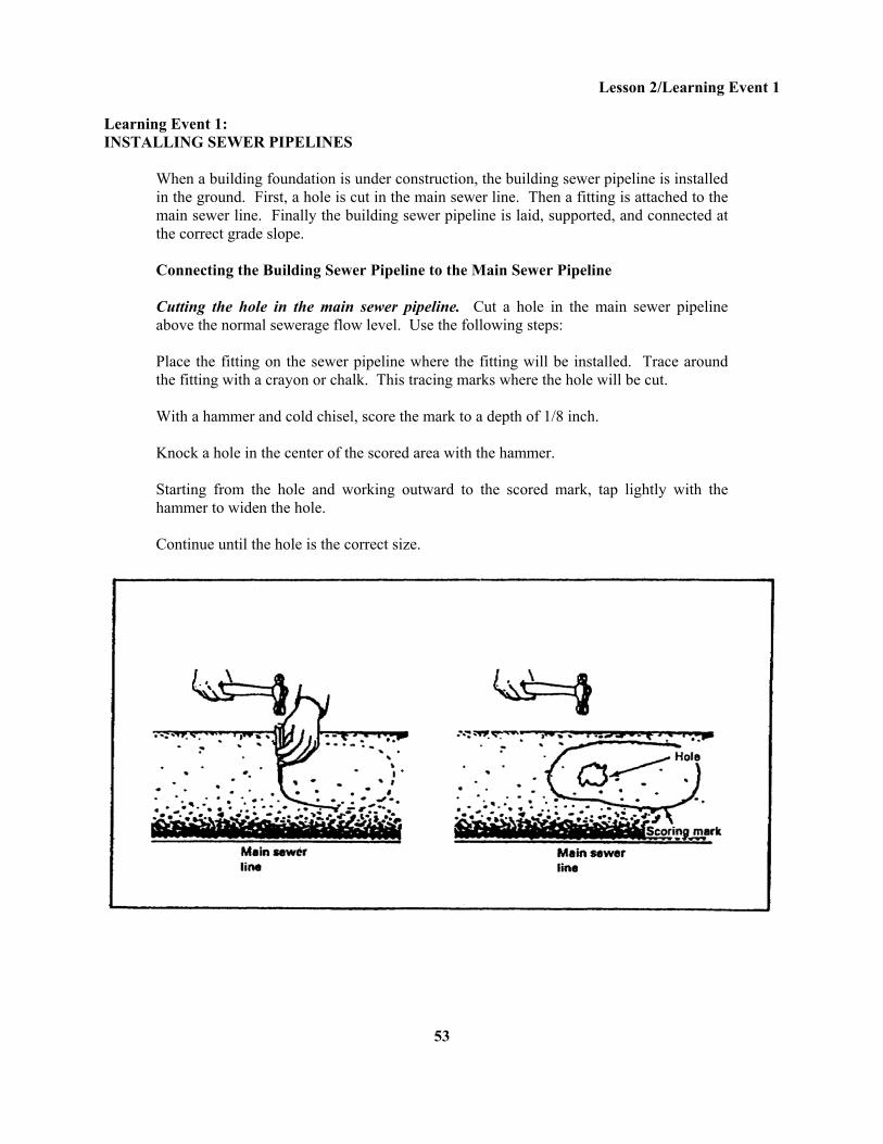
When a building foundation is under construction, the building sewer pipeline is installed in the ground. First, a hole is cut in the main sewer line. Then a fitting is attached to the main sewer line. Finally the building sewer pipeline is laid, supported, and connected at the correct grade slope. Connecting the Building Sewer Pipeline to the Main Sewer Pipeline Cutting the hole in the main sewer pipeline. Cut a hole in the main sewer pipeline above the normal sewerage flow level. Use the following steps: Place the fitting on the sewer pipeline where the fitting will be installed. Trace around the fitting with a crayon or chalk. This tracing marks where the hole will be cut. With a hammer and cold chisel, score the mark to a depth of 1/8 inch. Knock a hole in the center of the scored area with the hammer. Starting from the hole and working outward to the scored mark, tap lightly with the hammer to widen the hole. Continue until the hole is the correct size.
53
Lesson 2/Learning Event 1
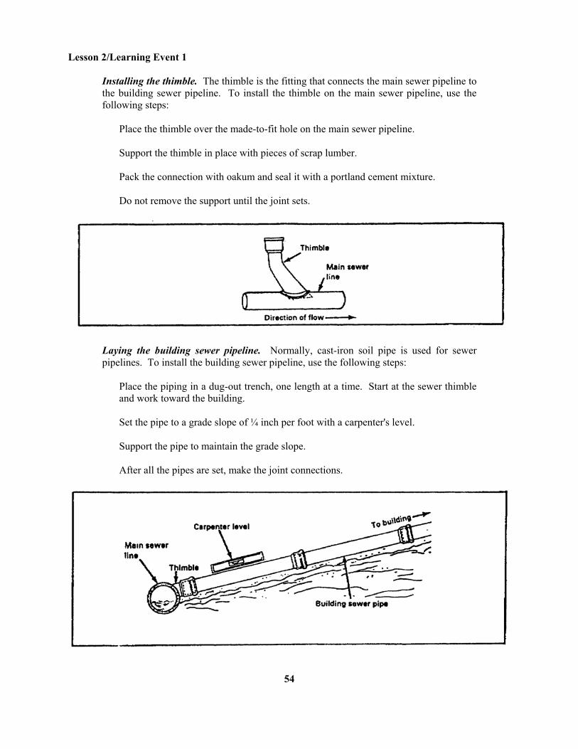
Installing the thimble. The thimble is the fitting that connects the main sewer pipeline to the building sewer pipeline. To install the thimble on the main sewer pipeline, use the following steps:
Place the thimble over the made-to-fit hole on the main sewer pipeline. Support the thimble in place with pieces of scrap lumber. Pack the connection with oakum and seal it with a portland cement mixture. Do not remove the support until the joint sets.
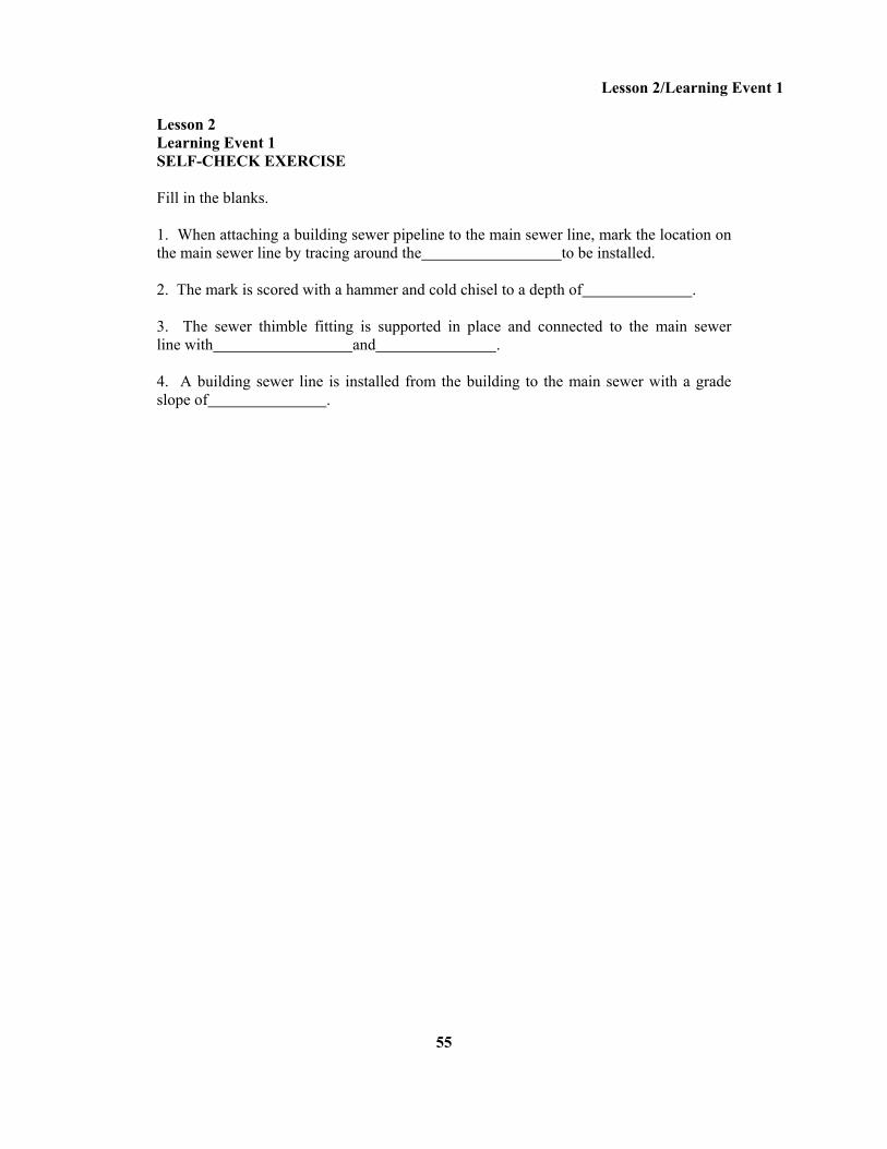
Laying the building sewer pipeline. Normally, cast-iron soil pipe is used for sewer pipelines. To install the building sewer pipeline, use the following steps:
Place the piping in a dug-out trench, one length at a time. Start at the sewer thimble and work toward the building. Set the pipe to a grade slope of ¼ inch per foot with a carpenter's level. Support the pipe to maintain the grade slope. After all the pipes are set, make the joint connections.
54
Lesson 2/Learning Event 1
Lesson 2 Learning Event 1 SELF-CHECK EXERCISE Fill in the blanks. 1. When attaching a building sewer pipeline to the main sewer line, mark the location on the main sewer line by tracing around the to be installed. 2. The mark is scored with a hammer and cold chisel to a depth of . 3. The sewer thimble fitting is supported in place and connected to the main sewer line with and . 4. A building sewer line is installed from the building to the main sewer with a grade slope of .
55
Lesson 2/Learning Event 1
SELF-CHECK EXERCISE SOLUTIONS 1. Fitting 2. 1/8 inch 3. Oakum and portland cement 4. inch per foot If your responses are the same, GREAT. Continue on with the lesson. If not, go back and review the material.
56
Lesson 2/Learning Event 2
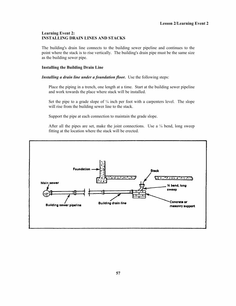
Learning Event 2: INSTALLING DRAIN LINES AND STACKS The building's drain line connects to the building sewer pipeline and continues to the point where the stack is to rise vertically. The building's drain pipe must be the same size as the building sewer pipe. Installing the Building Drain Line Installing a drain line under a foundation floor. Use the following steps:
Place the piping in a trench, one length at a time. Start at the building sewer pipeline and work towards the place where stack will be installed. Set the pipe to a grade slope of ¼ inch per foot with a carpenters level. The slope will rise from the building sewer line to the stack. Support the pipe at each connection to maintain the grade slope. After all the pipes are set, make the joint connections. Use a ¼ bend, long sweep fitting at the location where the stack will be erected.
57
Lesson 2/Learning Event 2
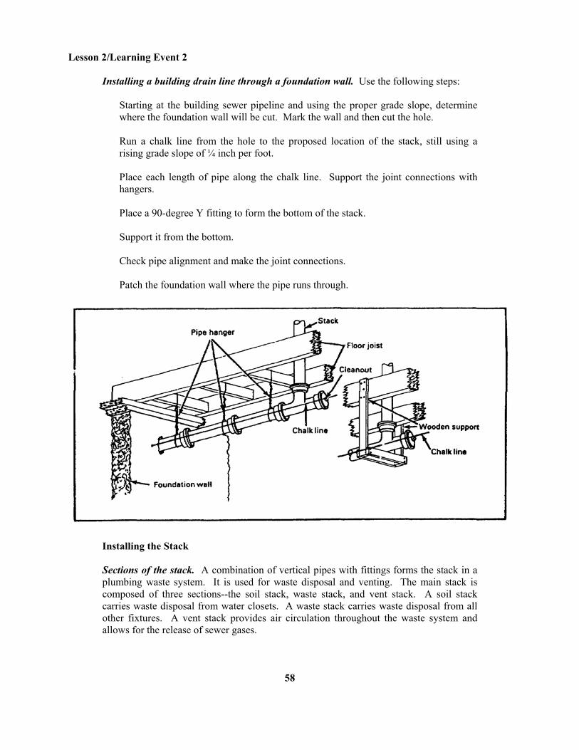
Installing a building drain line through a foundation wall. Use the following steps:
Starting at the building sewer pipeline and using the proper grade slope, determine where the foundation wall will be cut. Mark the wall and then cut the hole. Run a chalk line from the hole to the proposed location of the stack, still using a rising grade slope of ¼ inch per foot. Place each length of pipe along the chalk line. Support the joint connections with hangers. Place a 90-degree Y fitting to form the bottom of the stack. Support it from the bottom. Check pipe alignment and make the joint connections. Patch the foundation wall where the pipe runs through.
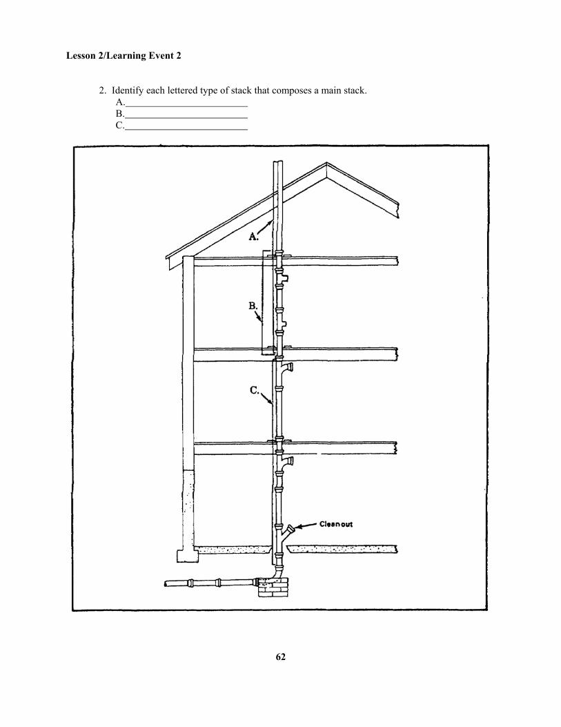
Installing the Stack Sections of the stack. A combination of vertical pipes with fittings forms the stack in a plumbing waste system. It is used for waste disposal and venting. The main stack is composed of three sections--the soil stack, waste stack, and vent stack. A soil stack carries waste disposal from water closets. A waste stack carries waste disposal from all other fixtures. A vent stack provides air circulation throughout the waste system and allows for the release of sewer gases.
58
Lesson 2/Learning Event 2
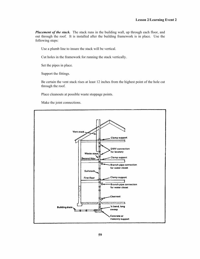
Placement of the stack. The stack runs in the building wall, up through each floor, and out through the roof. It is installed after the building framework is in place. Use the following steps:
Use a plumb line to insure the stack will be vertical. Cut holes in the framework for running the stack vertically. Set the pipes in place. Support the fittings. Be certain the vent stack rises at least 12 inches from the highest point of the hole cut through the roof. Place cleanouts at possible waste stoppage points. Make the joint connections.
59
Lesson 2/Learning Event 2
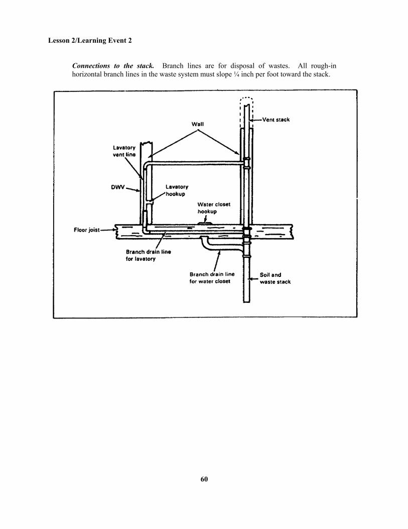
Connections to the stack. Branch lines are for disposal of wastes. All rough-in horizontal branch lines in the waste system must slope ¼ inch per foot toward the stack.
60
Lesson 2/Learning Event 2
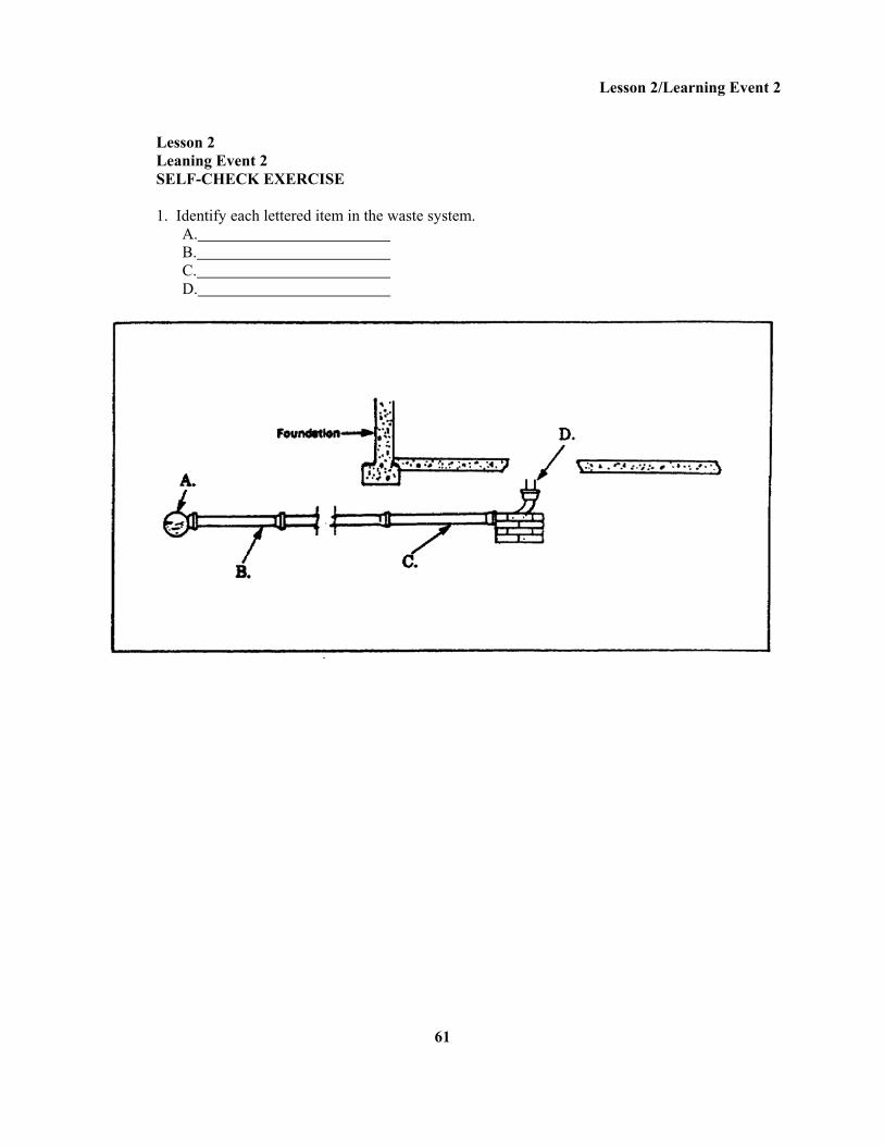
Lesson 2 Leaning Event 2 SELF-CHECK EXERCISE 1. Identify each lettered item in the waste system. A. B. C. D.
61
Lesson 2/Learning Event 2
2. Identify each lettered type of stack that composes a main stack. A. B. C.
62
Lesson 2/Learning Event 2
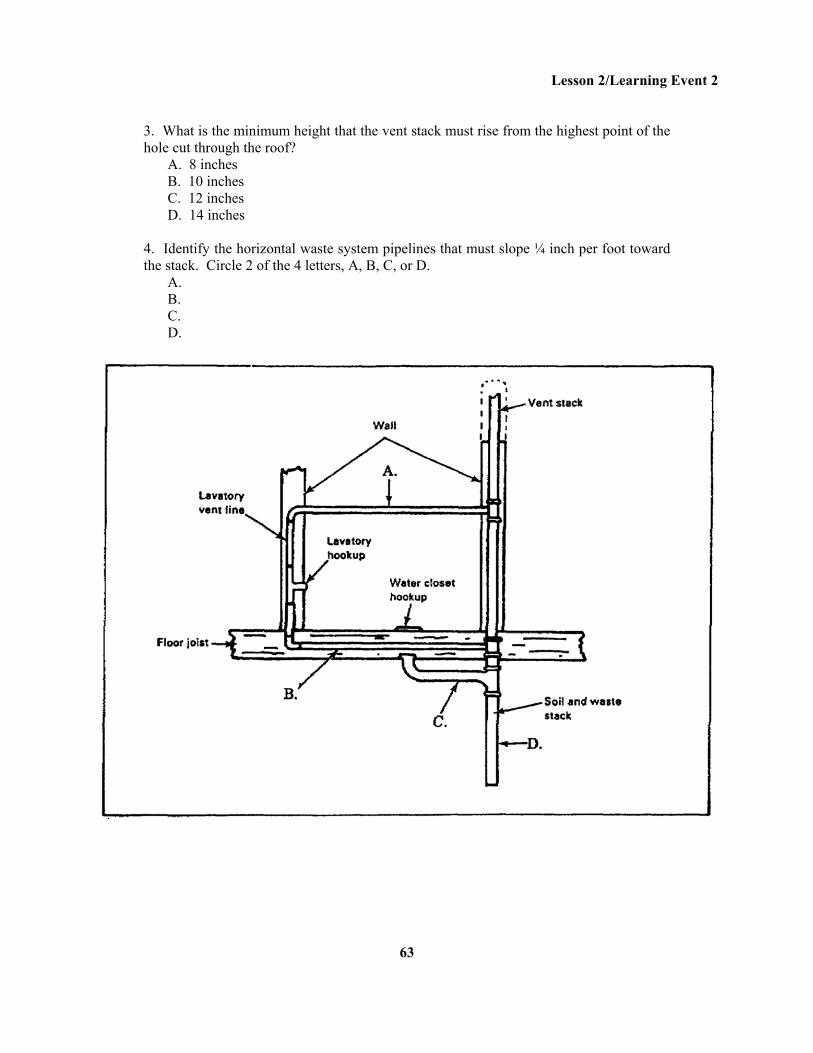
3. What is the minimum height that the vent stack must rise from the highest point of the hole cut through the roof? A. 8 inches B. 10 inches C. 12 inches D. 14 inches 4. Identify the horizontal waste system pipelines that must slope ¼ inch per foot toward the stack. Circle 2 of the 4 letters, A, B, C, or D. A. B. C. D.
63
Lesson 2/Learning Event 2
SELF-CHECK EXERCISE SOLUTIONS 1. A. Main sewer line B. Building sewer line C. Building drain line D. Stack 2. A. Vent stack B. Waste stack C. Soil stack 3. C. The minimum height that the vent stack must rise is 12 inches from the highest point of the hole cut through the roof. 4. B and C must slope ¼ inch toward the stack. B is the waste drain line for the lavatory. C is the waste drain lie for the water closet. If your responses are the same, GREAT. Continue on with the lesson. If not, go back and review the material.
64
Lesson 2/Learning Event 3
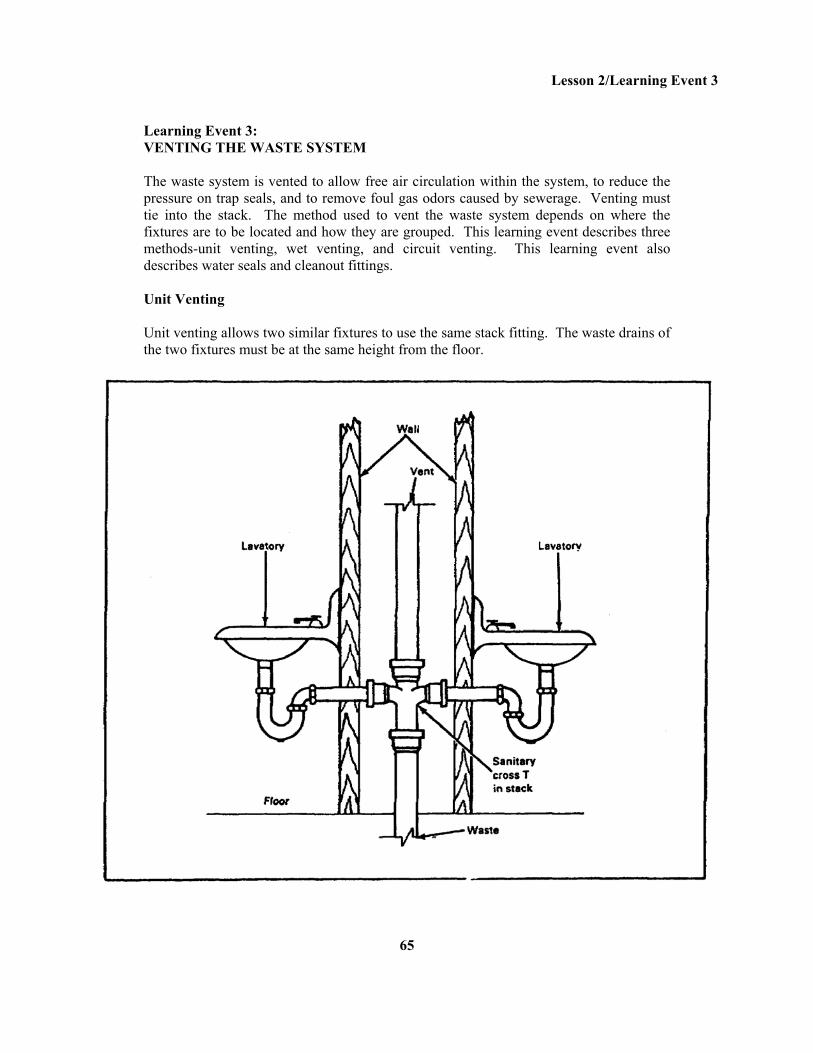
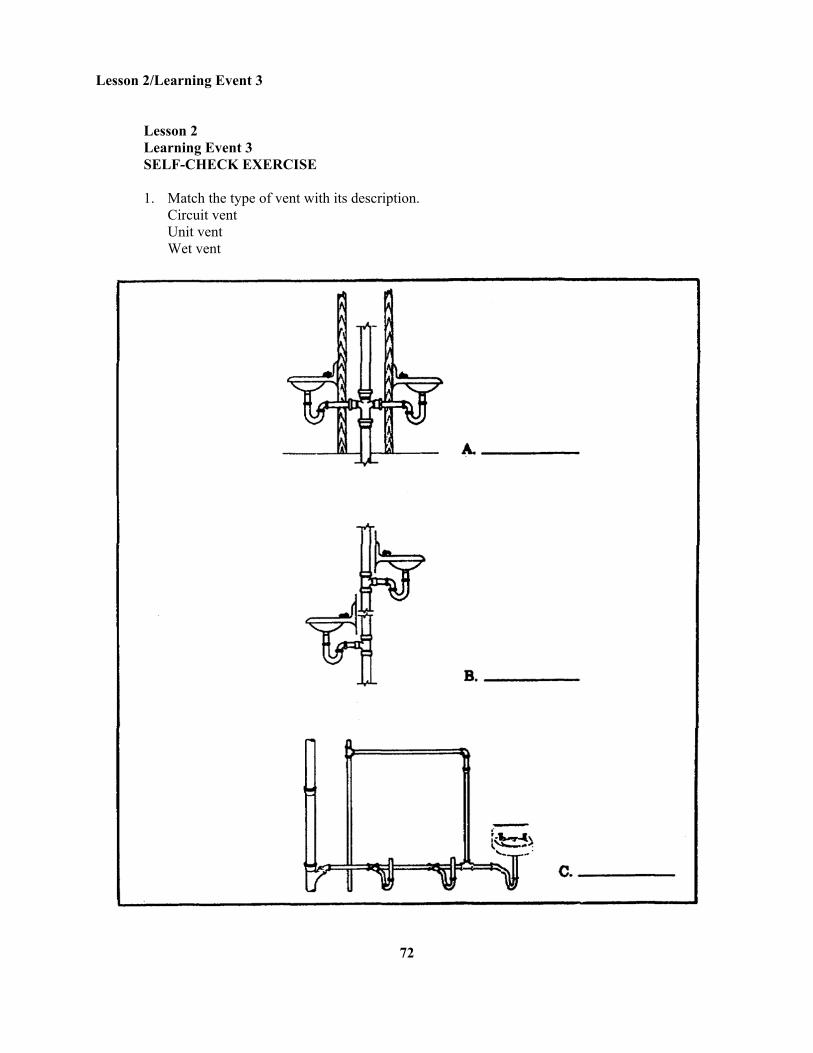
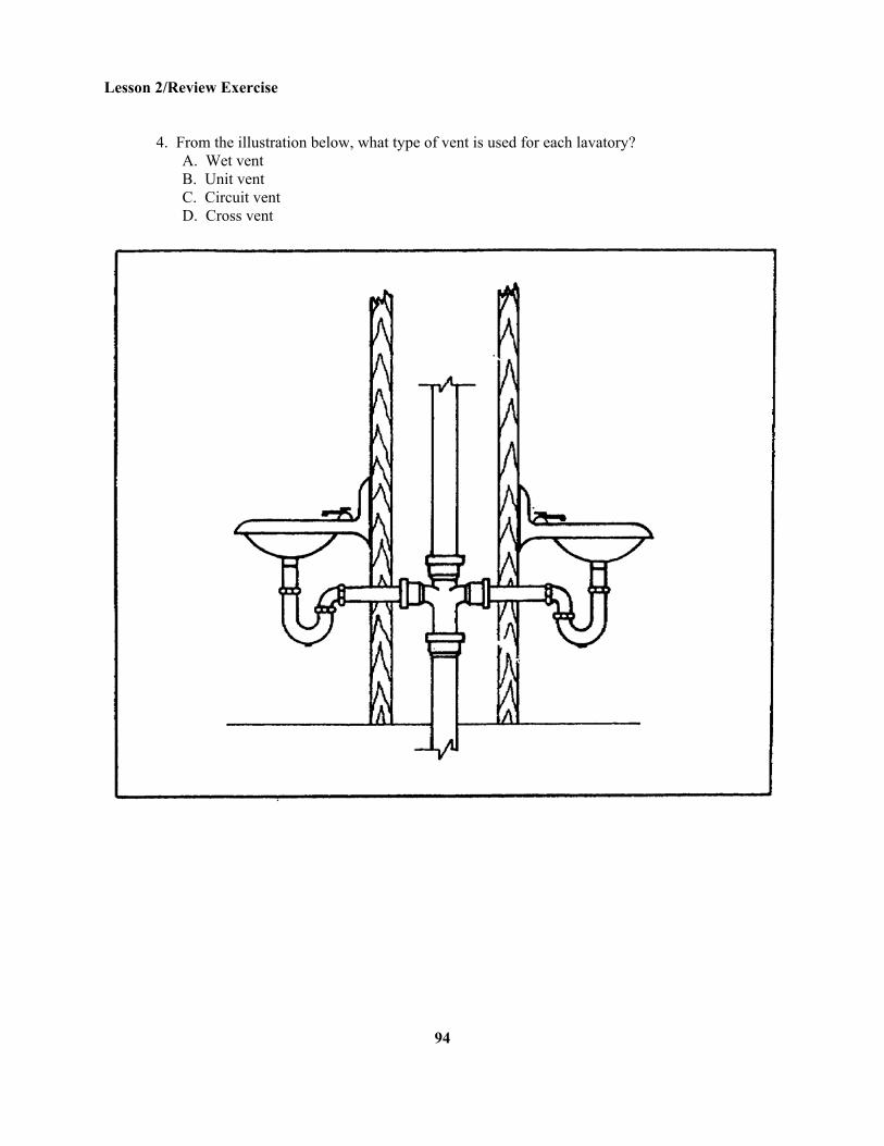
Learning Event 3: VENTING THE WASTE SYSTEM The waste system is vented to allow free air circulation within the system, to reduce the pressure on trap seals, and to remove foul gas odors caused by sewerage. Venting must tie into the stack. The method used to vent the waste system depends on where the fixtures are to be located and how they are grouped. This learning event describes three methods-unit venting, wet venting, and circuit venting. This learning event also describes water seals and cleanout fittings. Unit Venting Unit venting allows two similar fixtures to use the same stack fitting. The waste drains of the two fixtures must be at the same height from the floor.
65
Lesson 2/Learning Event 3
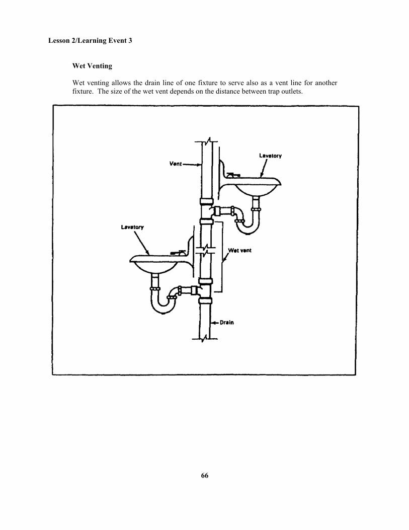
Wet Venting Wet venting allows the drain line of one fixture to serve also as a vent line for another fixture. The size of the wet vent depends on the distance between trap outlets.
66
Lesson 2/Learning Event 3
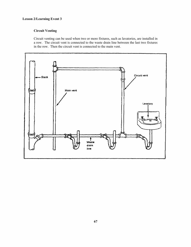
Circuit Venting Circuit venting can be used when two or more fixtures, such as lavatories, are installed in a row. The circuit vent is connected to the waste drain line between the last two fixtures in the row. Then the circuit vent is connected to the main vent.
67
Lesson 2/Learning Event 3
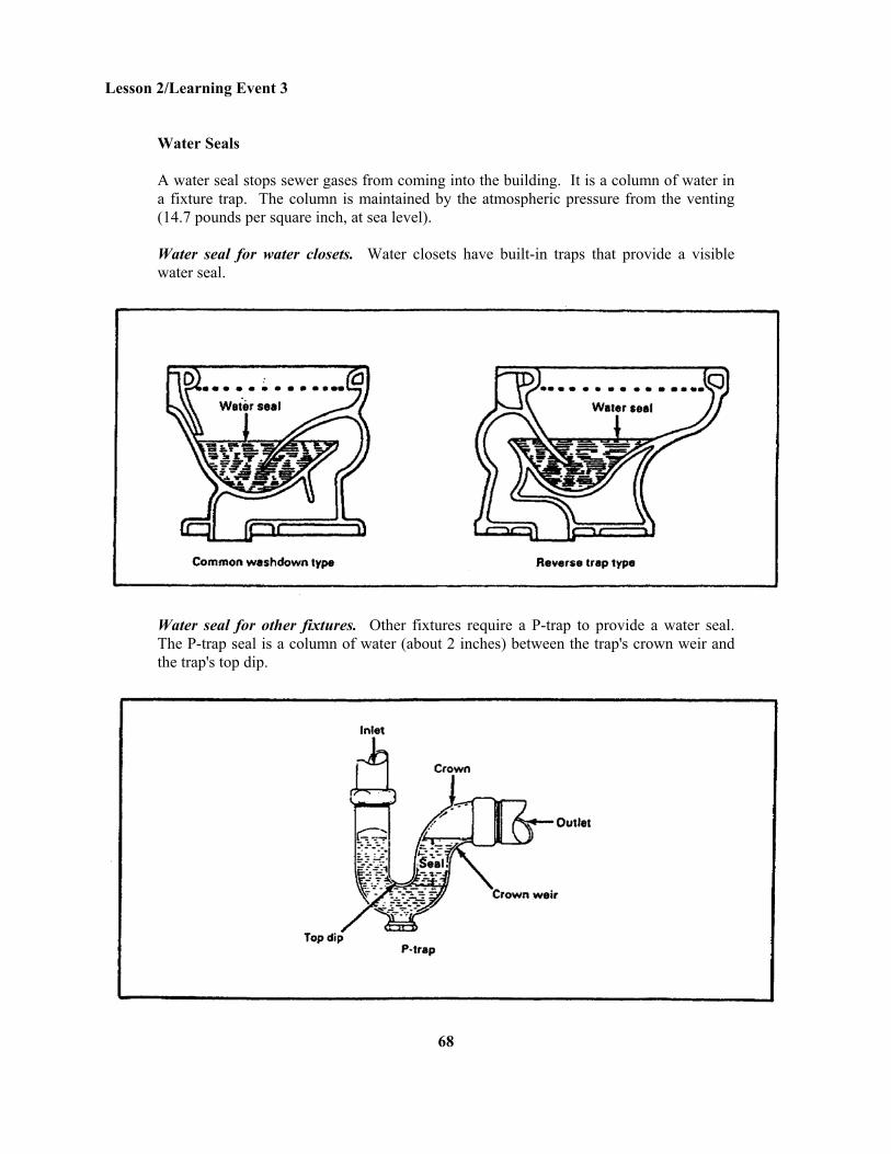
Water Seals A water seal stops sewer gases from coming into the building. It is a column of water in a fixture trap. The column is maintained by the atmospheric pressure from the venting (14.7 pounds per square inch, at sea level). Water seal for water closets. Water closets have built-in traps that provide a visible water seal.
Water seal for other fixtures. Other fixtures require a P-trap to provide a water seal. The P-trap seal is a column of water (about 2 inches) between the trap's crown weir and the trap's top dip.
68
Lesson 2/Learning Event 3
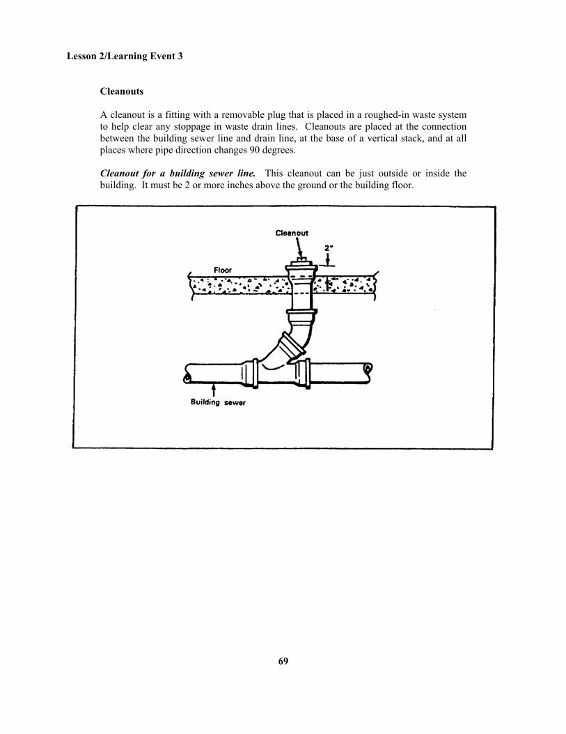
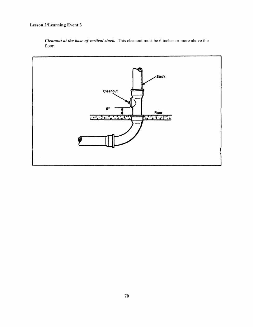
Cleanouts A cleanout is a fitting with a removable plug that is placed in a roughed-in waste system to help clear any stoppage in waste drain lines. Cleanouts are placed at the connection between the building sewer line and drain line, at the base of a vertical stack, and at all places where pipe direction changes 90 degrees. Cleanout for a building sewer line. This cleanout can be just outside or inside the building. It must be 2 or more inches above the ground or the building floor.
69
Lesson 2/Learning Event 3
Cleanout at the base of vertical stack. This cleanout must be 6 inches or more above the floor.
70
Lesson 2/Learning Event 3
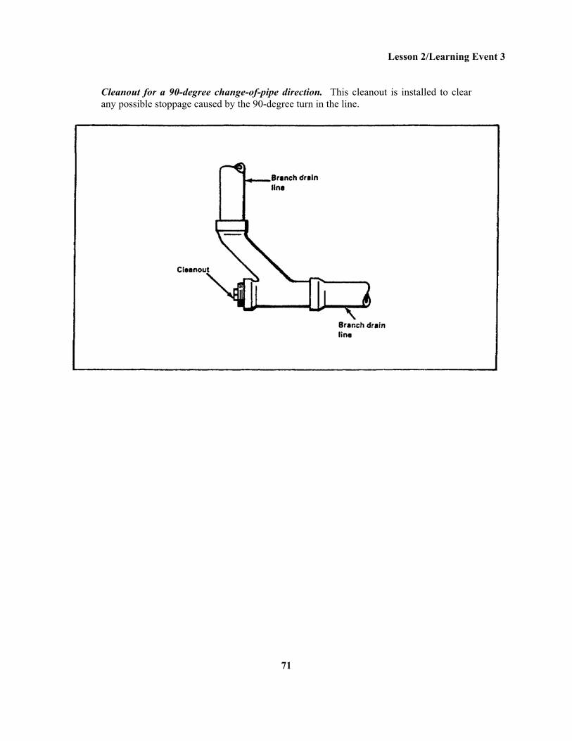
Cleanout for a 90-degree change-of-pipe direction. This cleanout is installed to clear any possible stoppage caused by the 90-degree turn in the line.
71
Lesson 2/Learning Event 3
Lesson 2 Learning Event 3 SELF-CHECK EXERCISE 1. Match the type of vent with its description. Circuit vent Unit vent Wet vent
72
Lesson 2/Learning Event 3 2. The water seal in a P-trap between the crown weir and the top dip is- A. 1 inch B. 2 inches C. 3 inches D. 4 inches 3. The cleanout for a building sewer line must be more than- A. 6 inches above floor B. 4 inches above floor C. 3 inches above floor D. 2 inches above floor 4. The cleanout at the base of a stack in a building must be- A. 2 inches above floor B. 4 inches above floor C. 6 inches above floor D. 8 inches above floor 5. A cleanout is installed when a pipe run changes direction by- A. 22½ degrees B. 33 1/3 degrees C. 42 degrees D. 90 degrees
73
Lesson 2/Learning Event 3
SELF-CHECK EXERCISE SOLUTIONS 1. A. Unit vent B. Wet vent C. Circuit vent 2. B 3. D 4. C 5. D If your responses are the same, GREAT. Continue on with the lesson. If not, go back and review the material.
74
Lesson 2/Learning Event 4
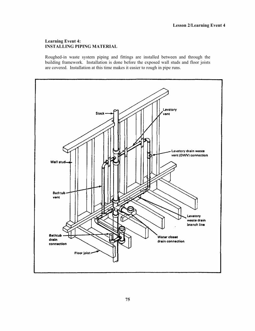
Learning Event 4: INSTALLING PIPING MATERIAL Roughed-in waste system piping and fittings are installed between and through the building framework. Installation is done before the exposed wall studs and floor joists are covered. Installation at this time makes it easier to rough in pipe runs.
75
Lesson 2/Learning Event 4
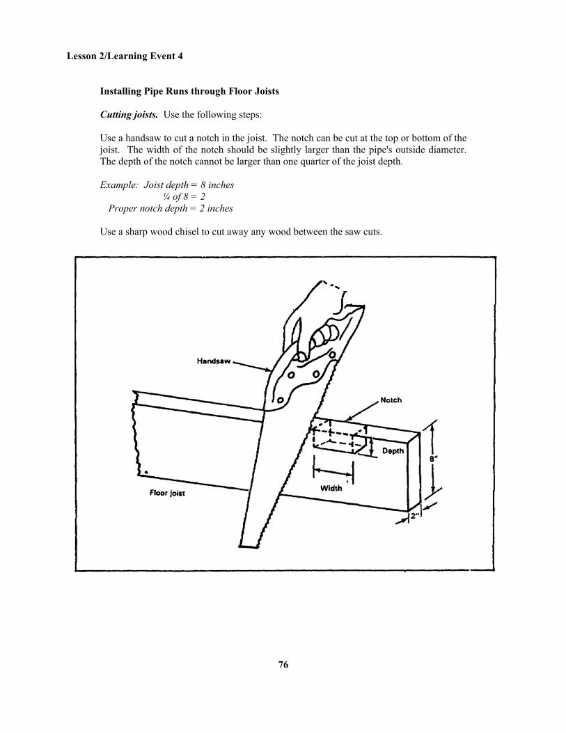
Installing Pipe Runs through Floor Joists Cutting joists. Use the following steps: Use a handsaw to cut a notch in the joist. The notch can be cut at the top or bottom of the joist. The width of the notch should be slightly larger than the pipe's outside diameter. The depth of the notch cannot be larger than one quarter of the joist depth. Example: Joist depth = 8 inches ¼ of 8 = 2 Proper notch depth = 2 inches Use a sharp wood chisel to cut away any wood between the saw cuts.
76
Lesson 2/Learning Event 4
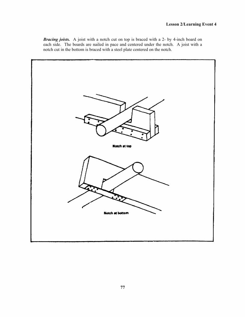
Bracing joists. A joist with a notch cut on top is braced with a 2- by 4-inch board on each side. The boards are nailed in pace and centered under the notch. A joist with a notch cut in the bottom is braced with a steel plate centered on the notch.
77
Lesson 2/Learning Event 4
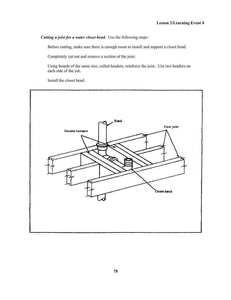
Cutting a joist for a water closet bend. Use the following steps:
Before cutting, make sure there is enough room to install and support a closet bend. Completely cut out and remove a section of the joist. Using boards of the same size, called headers, reinforce the joist. Use two headers on each side of the cut. Install the closet bend.
78
Lesson 2/Learning Event 4
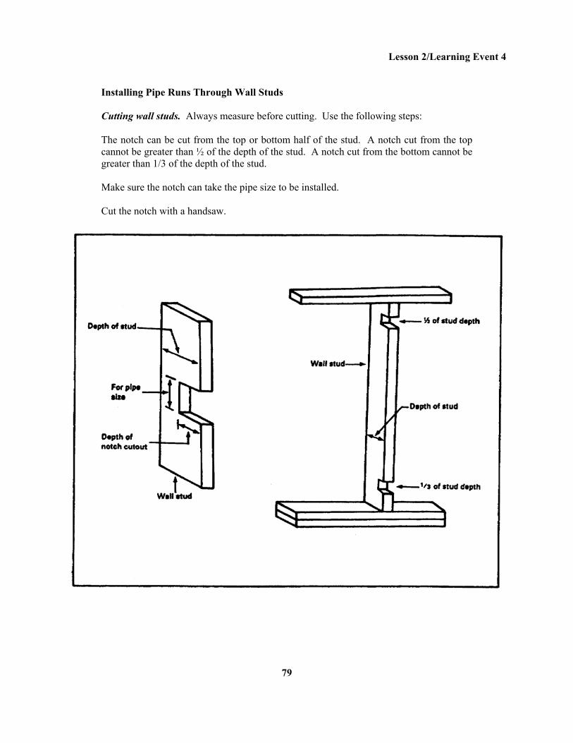
Installing Pipe Runs Through Wall Studs Cutting wall studs. Always measure before cutting. Use the following steps: The notch can be cut from the top or bottom half of the stud. A notch cut from the top cannot be greater than ½ of the depth of the stud. A notch cut from the bottom cannot be greater than 1/3 of the depth of the stud. Make sure the notch can take the pipe size to be installed. Cut the notch with a handsaw.
79
Lesson 2/Learning Event 4
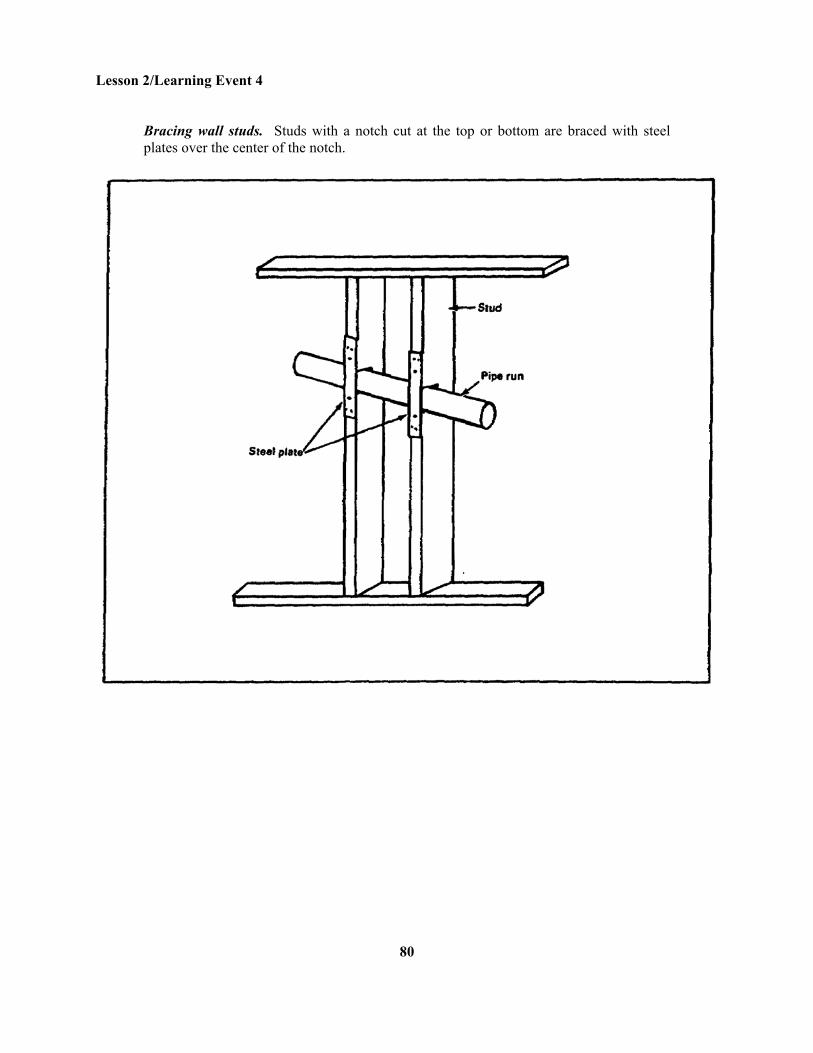
Bracing wall studs. Studs with a notch cut at the top or bottom are braced with steel plates over the center of the notch.
80
Lesson 2/Learning Event 4
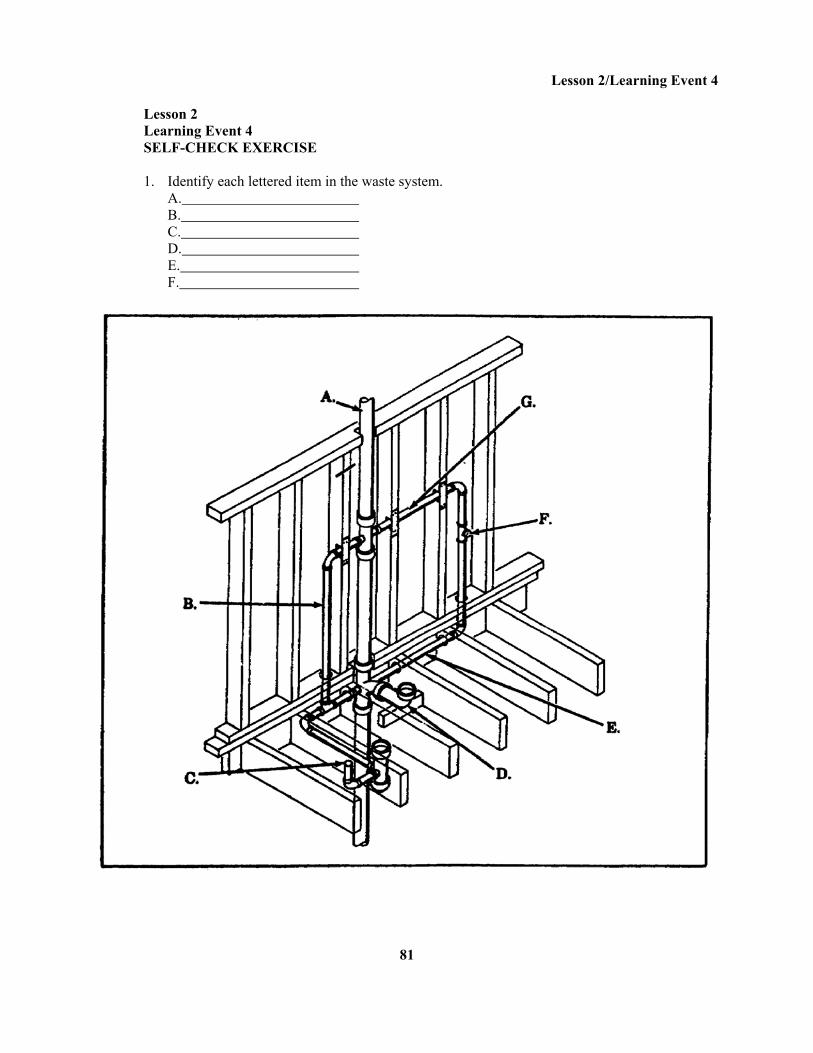
Lesson 2 Learning Event 4 SELF-CHECK EXERCISE 1. Identify each lettered item in the waste system. A. B. C. D. E. F.
81
Lesson 2/Learning Event 4
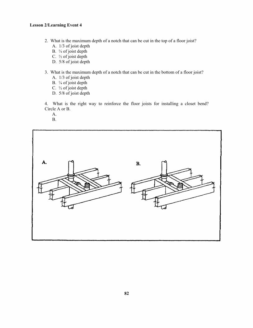
2. What is the maximum depth of a notch that can be cut in the top of a floor joist? A. 1/3 of joist depth B. ¼ of joist depth C. ½ of joist depth D. 5/8 of joist depth 3. What is the maximum depth of a notch that can be cut in the bottom of a floor joist? A. 1/3 of joist depth B. ¼ of joist depth C. ½ of joist depth D. 5/8 of joist depth 4. What is the right way to reinforce the floor joists for installing a closet bend? Circle A or B. A. B.
82
Lesson 2/Learning Event 4
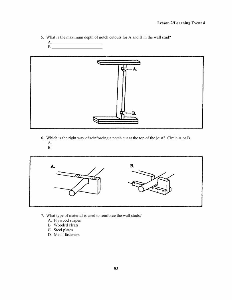
5. What is the maximum depth of notch cutouts for A and B in the wall stud? A. B.
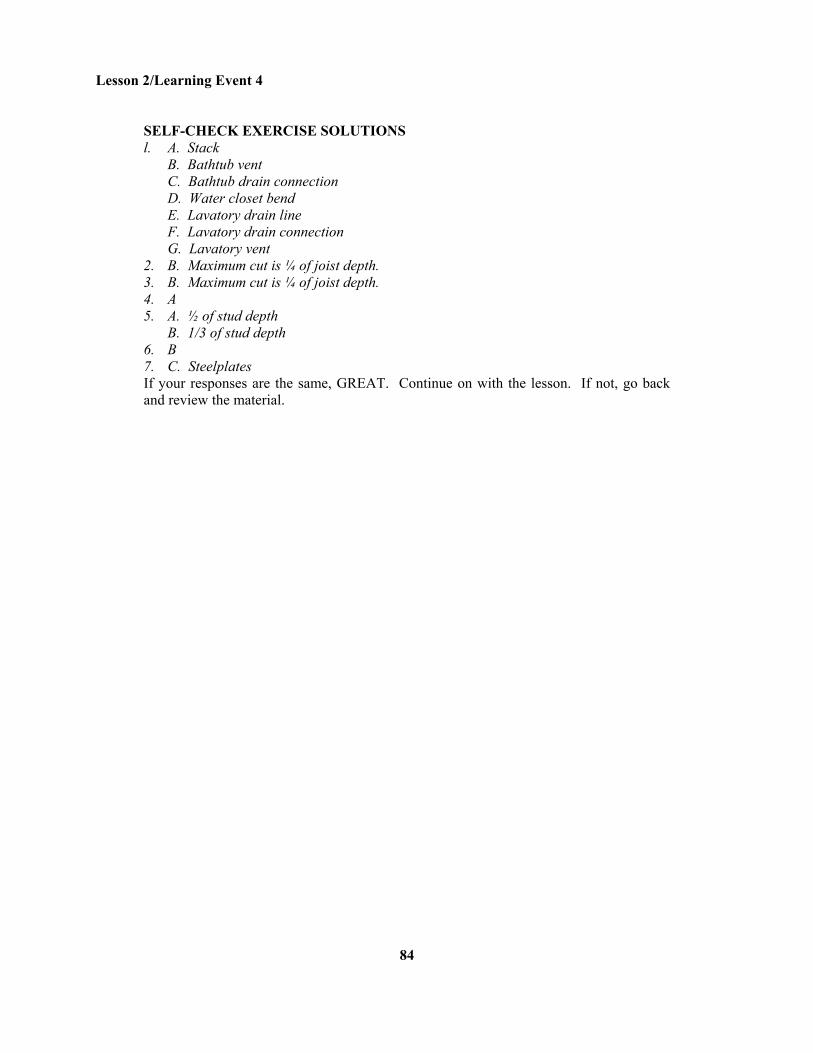
6. Which is the right way of reinforcing a notch cut at the top of the joist? Circle A or B. A. B.
7. What type of material is used to reinforce the wall studs? A. Plywood stripes B. Wooded cleats C. Steel plates D. Metal fasteners
83
Lesson 2/Learning Event 4
SELF-CHECK EXERCISE SOLUTIONS l. A. Stack B. Bathtub vent C. Bathtub drain connection D. Water closet bend E. Lavatory drain line F. Lavatory drain connection G. Lavatory vent 2. B. Maximum cut is ¼ of joist depth. 3. B. Maximum cut is ¼ of joist depth. 4. A 5. A. ½ of stud depth B. 1/3 of stud depth 6. B 7. C. Steelplates If your responses are the same, GREAT. Continue on with the lesson. If not, go back and review the material.
84
Lesson 2/Learning Event 5
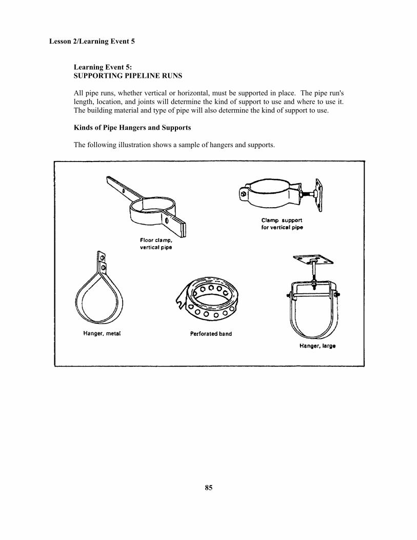
Learning Event 5: SUPPORTING PIPELINE RUNS All pipe runs, whether vertical or horizontal, must be supported in place. The pipe run's length, location, and joints will determine the kind of support to use and where to use it. The building material and type of pipe will also determine the kind of support to use. Kinds of Pipe Hangers and Supports The following illustration shows a sample of hangers and supports.
85
Lesson 2/Learning Event 5
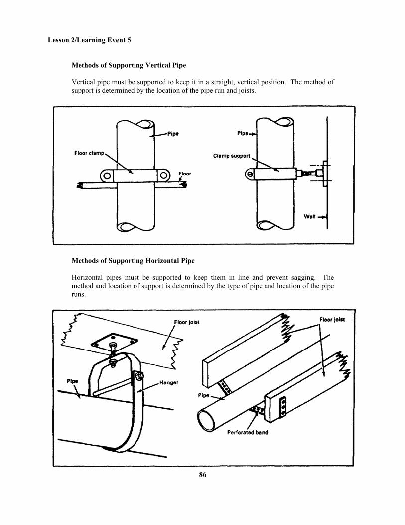
Methods of Supporting Vertical Pipe Vertical pipe must be supported to keep it in a straight, vertical position. The method of support is determined by the location of the pipe run and joists.
Methods of Supporting Horizontal Pipe Horizontal pipes must be supported to keep them in line and prevent sagging. The method and location of support is determined by the type of pipe and location of the pipe runs.
86
Lesson 2/Learning Event 5
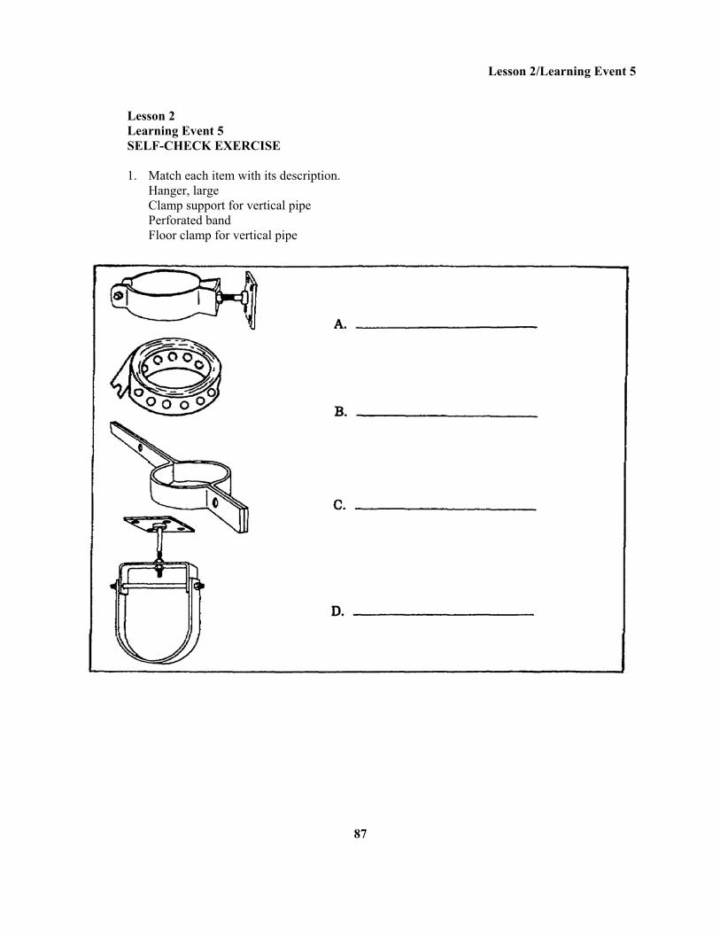
Lesson 2 Learning Event 5 SELF-CHECK EXERCISE 1. Match each item with its description. Hanger, large Clamp support for vertical pipe Perforated band Floor clamp for vertical pipe
87
Lesson 2/Learning Event 5
SELF-CHECK EXERCISE SOLUTIONS 1. A. Clamp support for vertical pipe B. Perforated band C. Floor clamp for vertical pipe D. Hanger, large If your responses are the same, GREAT. Continue on with the lesson. If not, go back and review the material.
88
Lesson 2/Learning Event 6
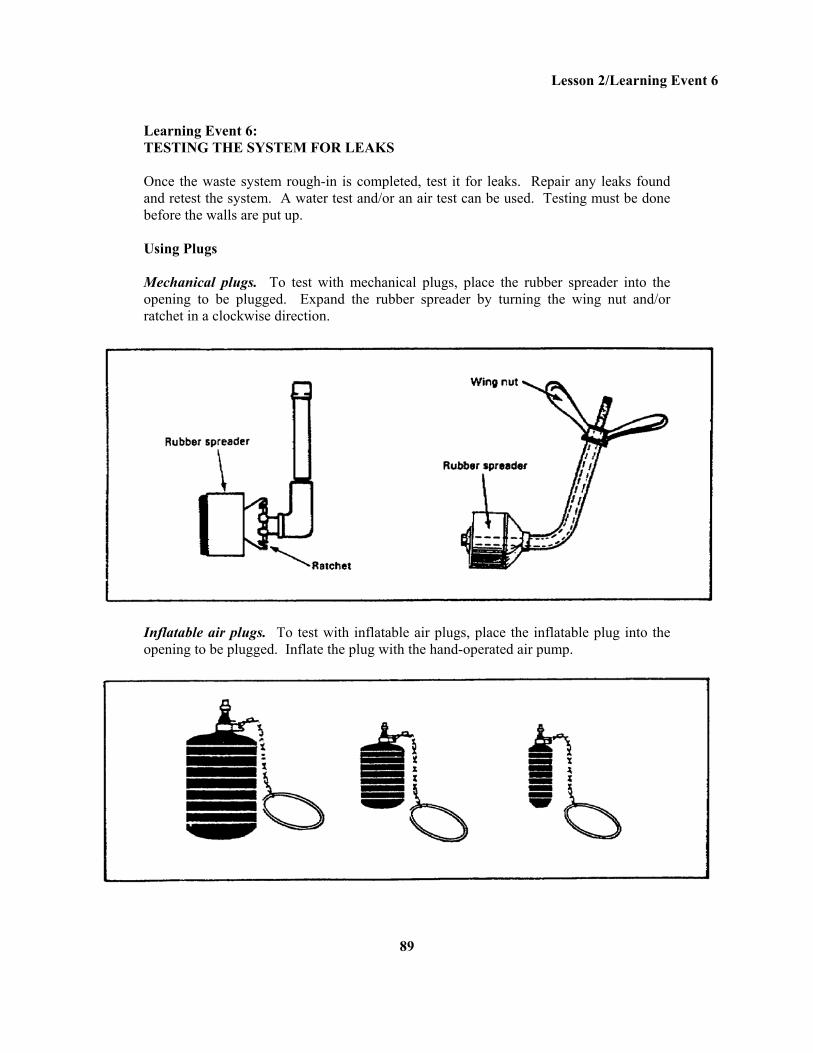
Learning Event 6: TESTING THE SYSTEM FOR LEAKS Once the waste system rough-in is completed, test it for leaks. Repair any leaks found and retest the system. A water test and/or an air test can be used. Testing must be done before the walls are put up. Using Plugs Mechanical plugs. To test with mechanical plugs, place the rubber spreader into the opening to be plugged. Expand the rubber spreader by turning the wing nut and/or ratchet in a clockwise direction.
Inflatable air plugs. To test with inflatable air plugs, place the inflatable plug into the opening to be plugged. Inflate the plug with the hand-operated air pump.
89
Lesson 2/Learning Event 6
Performing a Water Test A new system with oakum and lead joints must be filled with water at least 12 to 24 hours to allow the oakum in the joint to swell and form a water-tight seal. The system is then drained and tested. For all types of piping used in a waste system, use these steps to perform the test:
Seal off all openings, except the highest vent opening, with plugs. Threaded piping can be sealed off with threaded plugs or caps. Fill the system with water through the highest vent opening and check for water leaks. If the water level drops more than 4 inches in 30 minutes, check the system for leaks. Remove the water from the system. Repair any leaks. Retest
Performing an Air Test Use the following steps:
With plugs, seal off all openings except one for the test equipment and gage. Force air through the system until the gage reads 5 pounds per square inch (psi). Let the air pressure remain at 5 psi for 15 minutes. Put a soapy solution on the joints to test for leaks. Release the air. Repair any leaks. Retest.
90
Lesson 2/Learning Event 6
Lesson 2 Learning Event 6 SELF-CHECK EXERCISE 1. List the two types of plugs used to test a rough-in waste system. 2. When performing a water test on a rough-in waste system, you must check for leaks after the water level has dropped how many inches in 30 minutes? A. 6 B. 5 C. 4 D. 3 3. An air pressure of how many pounds per square inch (psi) must be maintained for 15 minutes during an air test in a rough-in waste system? A. 8 B. 7 C. 6 D. 5
91
Lesson 2/Learning Event 6
SELF-CHECK EXERCISE SOLUTIONS 1. Mechanical Inflatable 2. C. If water level drops over 4 inches, check system for leaks. 3. D. Five psi is applied to system for 15 minutes. If psi drops, check for leaks. If your responses are the same, GREAT. Continue on with the review exercise. If not, go back and review the material.
92
Lesson 2/Review Exercise
Lesson 2 REVIEW EXERCISE 1. What materials are used to attach a sewer thimble to the main sewer line? A. Oakum and lead B. Oakum and portland cement C. Oakum and solder D. Oakum and solvent cement 2. What is the grade slope used to install all horizontal drain waste piping in a rough-in waste system? A. ¼ inch per pipe B. ¼ inch per yard C. ¼ inch per foot D. ¼ inch per joint 3. What types of stacks make up a main stack? A. Soil and waste B. Soil and vent C. Soil, waste, and vent
93
Lesson 2/Review Exercise
4. From the illustration below, what type of vent is used for each lavatory? A. Wet vent B. Unit vent C. Circuit vent D. Cross vent
94
Lesson 2/Review Exercise
5. What is the correct trap seal for a P-trap between the crown weir and the top dip? A. 3 inches B. 2½ inches C. 2 inches D. 1½ inches 6. What is the minimum height required for a cleanout above the floor at the base of a stack? A. 2 inches B. 4 inches C. 6 inches D. 8 inches 7. When installing waste pipe runs, what is the maximum depth of a cut-out notch in a floor joist? A. 1/3 of joist depth B. ¼ of joist depth C. ½ of joist depth D. 5/8 of joist depth 8. When installing waste pipe runs, what is the maximum depth of a cut-out notch at the bottom half of a wall stud? A. 5/8 of stud depth B. ½ of stud depth C. ¼ of stud depth D. 1/3 of stud depth 9. How many minutes is water kept in a rough-in waste system during a water test? A. 15 B. 20 C. 25 D. 30 10. How many minutes is air pressure of 5 psi kept in a rough-in waste system during an air test? A. 25 B. 20 C. 15 D. 10
95
Lesson 2/Review Exercise
REVIEW EXERCISE SOLUTIONS 1. B (Page 54) 2. C (Page 54) 3. C (Page 58) 4. B (Page 65) 5. C (Page 68) 6. C (Page 69) 7. B (Page 76) 8. D (Page 79) 9. D (Page 90) 10. C (Page 90)
96