09 Plumbing Code Changes - Catawba County, North … drain (“09” NC Plumbing Code) That part of...
64
James Lamb Contact Information E‐mail: [email protected] E mail: [email protected] (828) 466‐5130 Ext.4 (desk) (828 ) 217 1007 ( ll) (828 ) 217‐1007 (cell)
Transcript of 09 Plumbing Code Changes - Catawba County, North … drain (“09” NC Plumbing Code) That part of...

James LambContact Information
E‐mail: [email protected] mail: [email protected]
(828) 466‐5130 Ext.4 (desk)
(828 ) 217 1007 ( ll)(828 ) 217‐1007 (cell)

• OLD CODE • NEW CODE• OLD CODE• 2006 NC Plumbing Code
• NEW CODE• 2009 NC Plumbing Code
• Based on the 2003 International Plumbing
C d ith NC
• Based on the 2006 International Code with
NC A d tCode with NC Amendments
NC Amendments

Course Names and Numbers
2009 NC Plumbing Code Chapters 1‐6 06‐216‐091
2009 NC Plumbing Code Chapters 7‐9 06‐217‐091
2009 NC Plumbing Code Chapters 10‐12 06‐218‐091g p

Licensed Design Professional Code Choices
• 2006 or 2009 NC Codes until July 01,2009
• 2009 NC Codes After July 01, 2009
• NC Rehab Code

(F R i )
Break Down Of Chapters(For Review)
• 1)Administration• 2)Definitions
• 9)Vents
• 10)Traps Interceptors And2)Definitions• 3)General Regulations• 4)Fixtures, Faucets And
Fi t Fitti
• 10)Traps, Interceptors And Separators
• 11)Storm DrainageFixture Fittings
• 5)Water Heaters• 6)Water Supply And
• 12)Special Piping And Storage Systems
13)R f d St d d) pp y
Distribution• 7)Sanitary Drainage
8)I di t/S i l W t
• 13)Referenced Standards
• Appendices
• 8)Indirect/Special Waste

From Ch. 11: 2009 NCBC (Accessibility)

Contact me for the complete letter from DOIContact me for the complete letter from DOI


TYPES OF CHANGES
• Change to IPC• Change in NC amendments• IPC Deletions• NC amendments in the “09” NCPC that have been removed reverting back to IPCremoved reverting back to IPC
• There are many changes in the numbering of code sections without being a code change. Thesesections without being a code change. These changes may not be noted during the class.

Building drain (“09” NC Plumbing Code) That part of the lowest piping of a drainage system that receives the discharge from soil, waste and other drainage pipes inside and that extends to 10 feet beyond the walls of the building and conveys the drainage to the building sewer.
The 06 NCPC read 10 feet in developed lengthA July 27 2007 memo from NCDOI revised this to developed lengthA July 27, 2007 memo from NCDOI revised this to developed length
(2006 IPC) For sake of discussionBUILDING DRAIN. That part of the lowest piping of a drainage system that
freceives the discharge from soil, waste and other drainage pipes inside and that extends 30 inches (762mm) in developed length of pipe beyond the exterior walls of the building and conveys the drainage to the building sewer. Building drains are usually considered to be the main drain of a drainageBuilding drains are usually considered to be the main drain of a drainage system within a structure. Building drains are horizontal (including vertical offsets) and are the portion of the drainage system that is at the lowest elevation in the structure. All horizontal drains above the elevation of the b ildi d i h i t l b h Th b ildi d i t i t t thbuilding drain are horizontal branches. The building drain terminates at the point where it exits the building [see commentary, Table 710.1(1)].

Bld.Drain
Foundation(Top view)
Septictank
Bld.Sewer
Building drain (“09” NC Plumbing Code) That part of the lowest piping of a drainage system thatpart of the lowest piping of a drainage system that receives the discharge from soil, waste and other drainage pipes inside and that extends to 10 feet beyond the walls of the building and conveys the drainage to the building sewer.

Bld
Foundation(top view)
Bld. drain
ldSeptictank
Bld. sewer
“06” NCPC Building Drain definition read 10 feet in developed length of pipe beyond the exterior of the walls of the building. This was revised by a memo from NCDOI dated July 27, 2007 to read 10 feet perpendicular from the exterior of the build

Foundation(top view)
Septict k
Bld. drain
tank
Building drain (“09” NC Plumbing Code) Th t t f th l t i i f d iThat part of the lowest piping of a drainage system that receives the discharge from soil, waste and other drainage pipes inside and that extends to 10 feet beyond the ywalls of the building and conveys the drainage to the building sewer.

(New Definition)FLOW CONTROL (Vented). A device installed upstream from the interceptor having an orifice that controls the rate of flow through the interceptor and an air intake (vent) downstream from the orifice that allows air to be drawn into the flow stream.
(The following is from the IPC Commentary) Referenced standard ASME A112.14.3 and Section 1003.3.4.2 use this term in connection with grease interceptors. This device is necessary to control the flow rate of waste th h th i t t d t t i i t i t i ti fthrough the interceptor and to entrain air to assist in separation of grease and oily waste from the water. Grease interceptors depend on having the necessary waste retention time to allow the fats, oils and grease to separate. If the influent flow rate is too high, the waste will pass through the p g , p ginterceptor too quickly, not allowing sufficient time for separation to occur. Entraining air in the waste influent will cause air bubbles to attach to grease globules, making them more buoyant and thereby enhancing the separation processprocess.

“06”06GREASE INTERCEPTOR. A passive interceptor whose rated flow exceeds 50 gpm (189 L/m).
“09”GREASE INTERCEPTOR. A plumbing appurtenance that is installed p g ppin a sanitary drainage system to intercept oily and greasy wastes from a wastewater discharge. Such device has the ability to intercept free-floating fats and oils.

(N D fi iti )(New Definition)GREASE REMOVAL DEVICE, AUTOMATIC (GRD). A plumbing appurtenance that is installed in the sanitary drainage system to intercept free-floating fats, oils and grease from wastewater discharge. Such a device operates on a time- or event-controlled basis and has the ability to remo e free floating fats oils and grease a tomaticall itho t inter ention from the serremove free-floating fats, oils and grease automatically without intervention from the user except for maintenance.
Referenced standard ASME A112.14.4 and Section 1003.3.4 use this term in connection with grease interceptors. An automatic grease removal device serves the same function as a grease interceptor with the distinction that the unpleasant aspect of grease removal is performed automatically. There are two main types of automatic GRD; pump out and skimmer type Theskimmer type. Thepump out type has an internal sensor that senses a build up of collected grease, liquefies it and pumps it out to an external container for proper environmental disposal. The skimmer type has a timer‐activated skimmer mechanism to mechanically collect and transport the ll d l h ll h l h kcollected grease to an external container. Both types usually have internal heaters to keep
thegrease in liquid form for easy pumping or skimming. Although the solids interceptor section of the GRD still requires manual maintenance to remove waste stream particulates such as q pfood scraps, broken glass and plastics, the task is relatively easy, thus having the likelihood of being performed regularly [see Commentary Figures 202(12) through 202(14)].

(Ne Definition)(New Definition)GRIDDED WATER DISTRIBUTION SYSTEM. A water distribution system where every water distribution pipe is interconnected so as to provide two or more paths to each fixture supply pipe. A gridded water distribution system is more hydraulically efficient than a parallel or branch line layout but not necessarily more cost efficient The design balances pressure and equalizesline layout but not necessarily more cost efficient. The design balances pressure and equalizes flow so that fixtures farthest from the water service entry point will operate under the same pressure and flow conditions as those closest to the water service entry point. Commentary Figure 202(15) illustrates various distribution layouts.

(N ti )(New section)310.5 Urinal partitions. Each urinal utilized by the public or employees shall occupy a separate area with walls or partitions to provide privacy. The construction of such walls or partitions shall incorporate waterproof, smooth, readily cleanable and nonabsorbent finish
f Th ll titi h ll b i t h i ht t th 12 i h (305 )surfaces. The walls or partitions shall begin at a height not more than 12 inches (305 mm) from and extend not less than 60 inches (1524 mm) above the finished floor surface. The walls or partitions shall extend from the wall surface at each side of the urinal a minimum of 18 inches (457
) t i t t l th 6 i h (152 ) b d th t t f t li f thmm) or to a point not less than 6 inches (152 mm) beyond the outermost front lip of the urinal measured from the finished back wall surface, whichever is greater.Exceptions:1. Urinal partitions shall not be required in a single occupant or unisex toilet room with a l k bl dlockable door.2. Toilet rooms located in day care and child care facilities and containing two or more urinals shall be permitted to have one urinal without partitions

Section 403Mi i Pl bi F ilitiMinimum Plumbing Facilities
T bl 403 1 f d Th l d f l d iTable 403.1 footnote d. The occupant load for seasonal outdoor seating and entertainment areas shall be included when determining the minimum number of facilities required. (This footnote applies to A-1, A-2, and A-3: see page 19 “09” NCPC)and A 3: see page 19 09 NCPC)
403.9.3 Occupant load for teachers and staff. (last sentence added back; was in 2002 NCPC, deleted in 2006 NCPC) Staffing ratio for grades 9 th h 12 i 70 t f l d 30 t lthrough 12 is 70-percent female and 30-percent male.
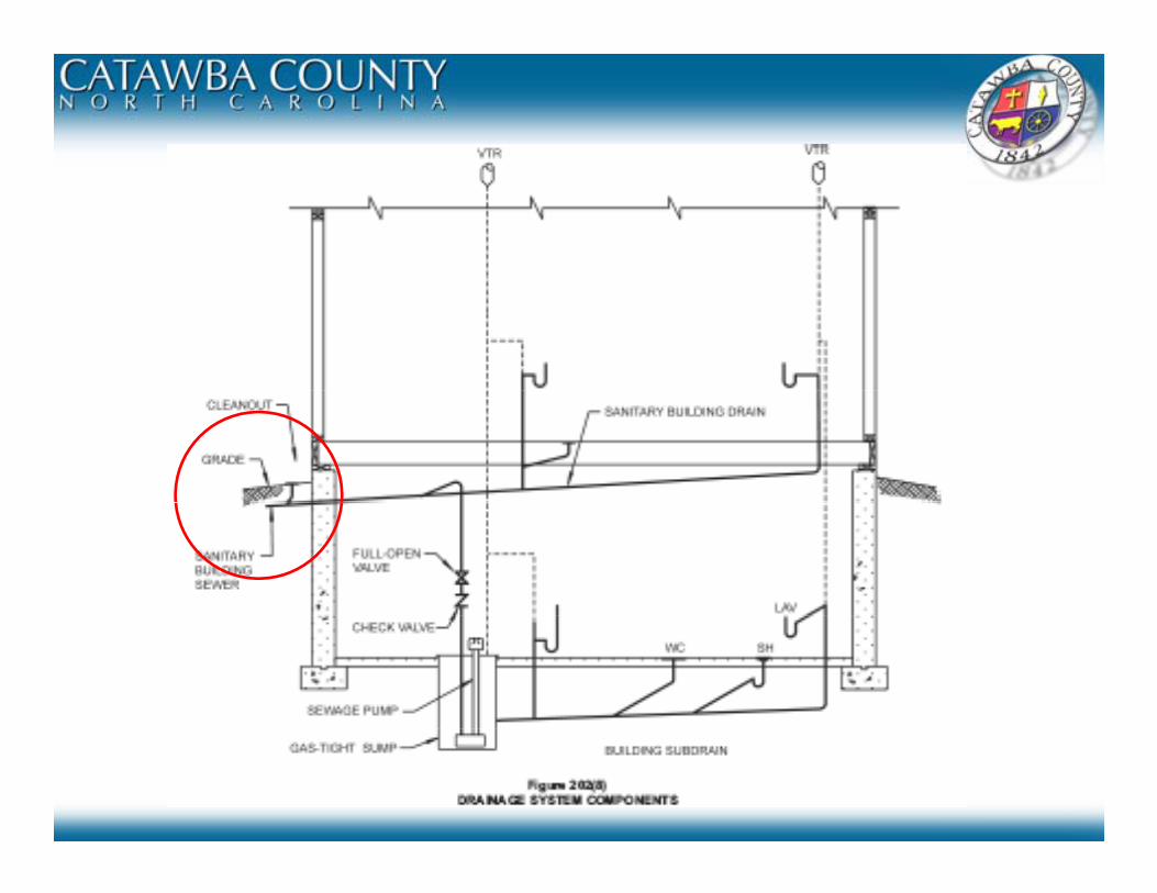
Section 405 Installation Of Fixtures

Section 405 Installation of Fixtures
405 3 1 Water closets urinals lavatories and bidets (new NC amendment )405.3.1 Water closets, urinals, lavatories and bidets. (new, NC amendment )Exception: For one and two family dwellings and townhouses see the North Carolina Residential Code.

Section 405 Installation of FixturesSection 405 Installation of FixturesR307.1 Space required Fixtures shall be spaced as per Figure R307.1.

405.3.2 Public lavatories. In employee and public toilet rooms, the required lavatory shall be located in the same room as the required water closet, except in Education K‐5, lavatories may be provided in a common toilet room vestibule, visible from the corridor.a common toilet room vestibule, visible from the corridor.

“06” NCPC06 NCPC417.5.2 Shower lining. Floors under shower compartments, except where prefabricated receptors have been provided, shall be lined and made water tight utilizing material complying with Sections 417.5.2.1 through 417.5.2.4. Such liners shall turn up on all id t l t 2 i h (51 ) b th fi i h d th h ld l l Li h ll bsides at least 2 inches (51 mm) above the finished threshold level. Liners shall be
recessed and fastened to an approved backing so as not to occupy the space required for wall covering, and shall not be nailed or perforated at any point less than 1 inch (25 mm) above the finished threshold. Liners shall be pitched one-fourth unit vertical in 12 ) punits horizontal (2-percent slope) and shall be sloped toward the fixture drains and be securely fastened to the waste outlet at the seepage entrance, making a water-tight joint between the liner and the outlet.
“09” NCPC417.5.2 Shower lining. Floors under shower compartments, except where prefabricated receptors have been provided, shall be lined and made water tight utilizing material complying with Sections 417.5.2.1 through 417.5.2.4. Such liners shall turn up on all sides at least 2 inches (51 mm) above the finished threshold level. Liners shall be recessed and fastened to an approved backing so as not to occupy the space required for wall covering and shall not be nailed or perforated at any point less than 1 inch (25for wall covering, and shall not be nailed or perforated at any point less than 1 inch (25 mm) above the finished threshold. Liners shall be securely fastened to the waste outlet at the seepage entrance, making a water-tight joint between the liner and the outlet.

“06”424.1.2 Waste fittings. Waste fittings shall conform to one of the standards listed in Tables 702.1 and 702 4 for above ground drainage and vent pipe and fittings or the waste fittings shall beand 702.4 for above-ground drainage and vent pipe and fittings, or the waste fittings shall be constructed of tubular stainless steel with a minimum wall thickness of 0.012 inch (0.30 mm), tubular copper alloy having a minimum wall thickness of 0.027 inch (0.69 mm) or tubular plastic complying with AS-TM F 409.
“09”424.1.2 Waste fittings. Waste fittings shall conform to ASME A112.18.2, ASTM F 409, CSA B125 or to one of the standards listed in Tables 702.1 and 702.4 for above-ground drainage and vent pipe and fittingsand fittings.

06”424.2 Hand showers. Hand-held showers shall conform to ASSE 1014 or CSA B125.
“09”424.2 Hand showers. Hand-held showers shall conform to ASME A112.18.1 or CSA B125.1. Hand-held showers shall provide backflow protection in accordance with ASME A112.18.1 or CSA B125.1 or shall be protected against backflow by a device complying with ASME A112.18.3.

(New Section)424.4 Multiple (gang) showers. Multiple (gang) showers supplied with a single-tempered water supply pipe shall have the water supply for such showers controlled by an approved automatic temperature control mixing valve that conforms to ASSE 1069 or CSA B125 or each shower headtemperature control mixing valve that conforms to ASSE 1069 or CSA B125, or each shower head shall be individually controlled by a balanced-pressure, thermostatic or combination balanced-pressure/thermostatic valve that conforms to ASSE 1016 or CSA B125 and is installed at the point of use. Such valves shall be equipped with a means to limit the maximumsetting of the valve to 120°F (49°C) which shall be field adjusted in accordance with thesetting of the valve to 120 F (49 C), which shall be field adjusted in accordance with the manufacturer’s instructions.
(New Section)424.5 Bathtub and whirlpool bathtub valves. The hot water supplied to bathtubs and whirlpool424.5 Bathtub and whirlpool bathtub valves. The hot water supplied to bathtubs and whirlpool bathtubs shall be limited to a maximum temperature of 120°F (49°C) by a water temperature limiting device that conforms to ASSE 1070, except where such protection is otherwise provided by a combination tub/shower valve in accordance with Section 424.3. (NC Amendment) Scald preventive valves are not required in dwelling units with individual water heaters set at 120 degreespreventive valves are not required in dwelling units with individual water heaters set at 120 degrees F.

504.7.1 Pan size and drain. Minimum diameter drain pipe changed from 1 inch to .75 inch.

The following sections have been added to the “09” NCPC after being deleted from the “06” NCPC.602.3.2 Minimum quantity.602.3.3 Water quality.602.3.4 Disinfection of system.602 3 5 Pumps602.3.5 Pumps602.3.5.1 Pump enclosure.

The following section was deleted from the “06” NCPC605 6 Flexible water connectors Flexible water connectors exposed to605.6 Flexible water connectors. Flexible water connectors exposed to continuous pressure shall conform to ASME A112.18.6. Access shall be provided to all flexible water connectors.
605.7 Valves. All valves shall be of an approved type and compatible with the type of piping material installed in the system. Ball valves, gate valves, globe valves and plug valves intended to supply drinking water shall meet the requirements of NSF 61.

(New section)605 21 P l l (PP) l ti J i t b t PP l ti i d fitti605.21 Polypropylene (PP) plastic. Joints between PP plastic pipe and fittings shall comply with Section 605.21.1 or 605.21.2.
(New section)( )605.21.1 Heat-fusion joints. Heat-fusion joints for polypropylene pipe and tubing joints shall be installed with socket-type heat-fused polypropylene fittings, butt-fusion polypropylene fittings or electrofusion polypropylene fittings. Joint surfaces shall be clean and free from moisture The joint shall be undisturbedsurfaces shall be clean and free from moisture. The joint shall be undisturbed until cool. Joints shall be made in accordance with ASTM F 2389.
(New section)605.21.2 Mechanical and compression sleeve joints. Mechanical and compression sleeve joints shall be installed in accordance with the manufacturer’s instructions.

608.2 Plumbing fixtures. The supply lines and fittings for every plumbing fixture shall be installed so as to prevent backflow. p g pPlumbing fixture fittings shall provide backflow protection in accordance with ASME A112.18.1.

Table 608.1. Application of Backflow Preventersadditional applicable standardsadditional applicable standards

(New section)608.16.10 Coffee machines and noncarbonated beverage di Th t l ti t ff hi ddispensers. The water supply connection to coffee machines and noncarbonated beverage dispensers shall be protected against backflow by a backflow preventer conforming to ASSE 1022 or by y p g yan air gap.


(New Sections)( )

708.3.5 Building drain and building sewer junction. There shall be a l t th j ti f th b ildi d i d th b ildi Thcleanout near the junction of the building drain and the building sewer. The
cleanout shall be outside the building wall and shall be brought up to the finished ground level. An approved two-way cleanout is allowed to be used at this location to serve as a required cleanout for both the building drain andthis location to serve as a required cleanout for both the building drain and building sewer. The cleanout at the junction of the building drain and building sewer shall not be required if the cleanout on a 3-inch (76 mm) or larger diameter soil stack is located within a developed length of not more than 15 feetdiameter soil stack is located within a developed length of not more than 15 feet (was 10 feet in the “06” NCPC) from the building drain and building sewer connection and is extended to the out-side of the building. The minimum size of the cleanout at the junction of the building drain and building sewer shall j g gcomply with Section 708.7. 9.

New section: However, did not change the code.

(f i )
Vents(for review)
Dry ventsVent Stacks
Wet VentsVent Stacks
Stack Vents
Branch Vents
Circuit Vents
Combination Drain and Vents
Waste Stack VentsBranch Vents
Relief Vents
Island Vents
Waste Stack Vents
Different Level Common Vents
Individual Vents

901.2.1 Venting required. Every trap and trapped fixture shall be vented in accordance with one of the venting methods specified in thi h t All fi t di h i d t f tthis chapter. All fixtures discharging down-stream from a water closet shall be individually vented except as provided in Section 911. (the highlighted NC amendment has been removed from the “09” NCPC)

“06”06
“09”09
Took out size of fixture drain column

908.3 Connection at different levels. Where the fixture drains connect at diff t l l th t h ll t ti l t i f th ti ldifferent levels, the vent shall connect as a vertical extension of the vertical drain. The vertical drain pipe connecting the two fixture drains shall be considered the vent for the lower fixture drain, and shall be sized in accordance with Table 908 3 The upper fixture shall not be a water closet or clotheswith Table 908.3. The upper fixture shall not be a water closet or clothes washer.

Section 912Section 912 Combination Waste and Vent System
(New section to NCPC)912.2.3 Vent size. The vent shall be sized for the total drainage fixture unit load in accordance with Section 916 2in accordance with Section 916.2.
(New section to NCPC)912 2 4 Fixture branch or drain The fixture branch or fixture drain shall912.2.4 Fixture branch or drain. The fixture branch or fixture drain shall connect to the combination drain and vent within a distance specified in Table 906.1. The combination drain and vent pipe shall be considered the vent for the fixture.

1002.1 Fixture traps. Each plumbing fixture shall be separately trapped by a water-seal trap, except as otherwise permitted by this code. The vertical di t f th fi t tl t t th t i h ll t d 24 i h (610distance from the fixture outlet to the trap weir shall not exceed 24 inches (610 mm) and the horizontal distance shall not exceed 30 inches (610 mm) measured from the centerline of the fixture outlet to the centerline of the inlet of the trap The height of a clothes washer standpipe above a trap shallthe trap. The height of a clothes washer standpipe above a trap shallconform to Section 802.4.Afixture shall not be double trapped.

Section 1003Interceptors and Separators
“06”1003.3 Grease traps and grease interceptors. Grease traps and grease interceptors shall comply with the requirements of Sections 1003.3.1 through 1003.3.4.2.
“09”1003 3 G i t t G i t t h ll l ith th1003.3 Grease interceptors. Grease interceptors shall comply with the requirements of Sections 1003.3.1 through 1003.3.5 or with the requirements of the local utility department or health department.

Section 1003Section 1003Interceptors and Separators
“06”“06”1003.3.1 Grease traps and grease interceptors required. A grease trap or grease interceptor shall be required to receive the drainage from fixtures and equipment with grease-laden waste located in food preparation areas, such as in restaurants, hotelgrease laden waste located in food preparation areas, such as in restaurants, hotel kitchens, hospitals, school kitchens, bars, factory cafeterias, or restaurants and clubs.
“09”1003 3 1 G i t t d t ti l1003.3.1 Grease interceptors and automatic grease removaldevices required. A grease interceptor or automatic grease removal device shall be required to receive the drainage from fixtures and equipment with grease-laden waste located in food preparation areas, such as in restaurants, hotel kitchens, hospitals, p p pschool kitchens, bars, factory cafeterias and clubs. Fixtures and equipment shall include pot sinks, prerinse sinks; soup kettles or similar devices; wok stations; floor drains or sinks into which kettles are drained; automatic hood wash units and dishwashers without prerinse sinks Grease interceptors and automatic grease removal devices shall receiveprerinse sinks. Grease interceptors and automatic grease removal devices shall receive waste only from fixtures and equipment that allow fats, oils or grease to be discharged.

Section 1003Interceptors and SeparatorsInterceptors and Separators
(New section)1003 3 5 A t ti l d i Wh t ti1003.3.5 Automatic grease removal devices. Where automatic grease removal devices are installed, such devices shall be located downstream of each fixture or multiple fixtures in accordance with the manufacturer’s instructions The automatic grease removal device shall be sized to pretreat theinstructions. The automatic grease removal device shall be sized to pretreat the measured or calculated flows for all connected fixtures or equipment. Ready access shall be provided for inspection and maintenance.

Appendix C: Gray Water Recycling Systems (which is adopted as part of the 2009 NCPC)
Appendix C: Gray Water Recycling Systems has expanded from 1page to 3 pages of text and 2 pages of illustrations.Gray water recycling is a big component of “green” building technology.Note: Section 301 3 of this code requires all plumbing fixtures that receive water or waste toNote: Section 301.3 of this code requires all plumbing fixtures that receive water or waste to discharge to the sanitary drainage system of the structure. In order to allow for the utilization of a gray water system, Section 301.3 should be revised to read as follows:301.3 Connections to drainage system. All plumbing fixtures, drains, appurtenances and appliances used to receive or discharge liquid wastes or sewage shall be directly connected to theappliances used to receive or discharge liquid wastes or sewage shall be directly connected to the sanitary drainage system of the building or premises, in accordance with the requirements of this code. This section shall not be construed to prevent indirect waste systems required by Chapter 8. Exception: Bathtubs, showers, lavatories, clothes washers and laundry trays shall not be required to discharge to the sanitary drainage system where such fixtures discharge to an approved grayto discharge to the sanitary drainage system where such fixtures discharge to an approved gray water system for flushing of water closets and urinals or for subsurface landscape irrigation.The text and illustrations are for two different types of gray water systems.
Section C102 Systems for Flushing Water Closets and Urinals:SectionC103 Subsurface Landscape irrigation Systems:SectionC103 Subsurface Landscape irrigation Systems:


Section 920 Single StackSection 920 Single Stack Plumbing Systems (SOVENT)

SoventSoventSovent
Sovent is a patented engineered combination waste and vent system for multi-story buildings.

S t S tSovent System