Plumbing Code
44
The International Plumbing Code: A Guide for Use and Adoption
-
Upload
amirthraj74 -
Category
Documents
-
view
114 -
download
3
description
Plumbing and piping
Transcript of Plumbing Code
The InternationalPlumbing Code:
A Guide
for Use
and Adoption
Publication Date: June 1998
Copyright © 1998
by
INTERNATIONAL CODE COUNCIL, INC.
ALL RIGHTS RESERVED. The International Plumbing Code: A Guide for Use and Adoption is a copyrighted work
owned by the International Code Council, Inc. Without advance written permission from the copyright owner, no
part of this book may be reproduced, distributed, or transmitted in any form or by any means, including, without
limitation, electronic, optical or mechanical means (by way of example, and not limitation, photocopying, or recording
by or in an information storage retrieval system). For information on permission to copy material exceeding fair use,
please contact: President, International Code Council, 5203 Leesburg Pike, Suite 708, Falls Church, Virginia
22041-3401. (Phone 703-931-4533).
Trademarks: “International Code Council,” the “International Code Council” logo and the “International Plumbing
Code” are trademarks of the International Code Council, Inc.
Published in cooperation with:
BUILDING OFFICIALS AND CODE ADMINISTRATORS INTERNATIONAL, INC.
4051 West Flossmoor Road • Country Club Hills, Illinois 60478-5795
(708) 799-2300
INTERNATIONAL CONFERENCE OF BUILDING OFFICIALS
5360 Workman Mill Road • Whittier, California 90601-2298
(562) 699-0541
SOUTHERN BUILDING CODE CONGRESS INTERNATIONAL, INC.
900 Montclair Road • Birmingham, Alabama 35213-1206
(205) 591-1853
Foreword
The International Plumbing Code (IPC) was developed by the International Code Council (ICC) to be the most
technically up-to-date plumbing code. The IPC is founded on plumbing principles utilized in the plumbing codes of
more than 30 states across the country. Every code requirement is based on engineering principles, years of
research, and field experience. When a modern, up-to-date plumbing code is introduced to new regions of the
country, it is subject to criticism for the changes that are instituted. Although new to these areas, the requirements
within the IPC represent plumbing practices utilized throughout the United States. The ICC developed this Guide
for Use and Adoption to help assist in the analysis of the code.
When reviewing the International Plumbing Code some requirements may appear to be new. It should be noted
that every code requirement has been enforced in a plumbing code somewhere in the United States. The IPC is
the first attempt to accumulate all of the acceptable plumbing practices into one code.
The major technical provisions of the IPC are evaluated in this guide. Commentary is provided, with reference
to supporting documentation, that justifies the technical content of the code.
The IPC should not be considered a liberal code, conservative code, permissive code, restrictive code,
cost-saving code, or increased-cost code. The IPC is merely a very technical plumbing code. It was developed with
the philosophy of recognizing all acceptable plumbing practices that have been proven safe and reliable in the
annals of plumbing.
This guide is not intended to criticize any other plumbing code. It is only intended to provide insight into the
technical substantiation of the IPC.
THE IPC: A Guide for Use and Adoption 3

4 THE IPC: A Guide for Use and Adoption
Part 1Overview of the
International Plumbing Code
Scope: The International Plumbing Code (IPC) was the
first code developed with the full cooperation of the
three model code groups: Building Officials and Code
Administrators International, Inc. (BOCA), International
Conference of Building Officials (ICBO), and Southern
Building Code Congress International, Inc. (SBCCI).
The intent was to regulate plumbing with the most
technically accurate code. The original intent of the IPC
was to recognize all acceptable methods for the various
plumbing systems. The Code did not attempt to restrict
arbitrarily any method, material, concept or system.
Since its initial development, the IPC has been updated
through an annual code change process with participa-
tion from nationally recognized industry experts.
Development of the Code
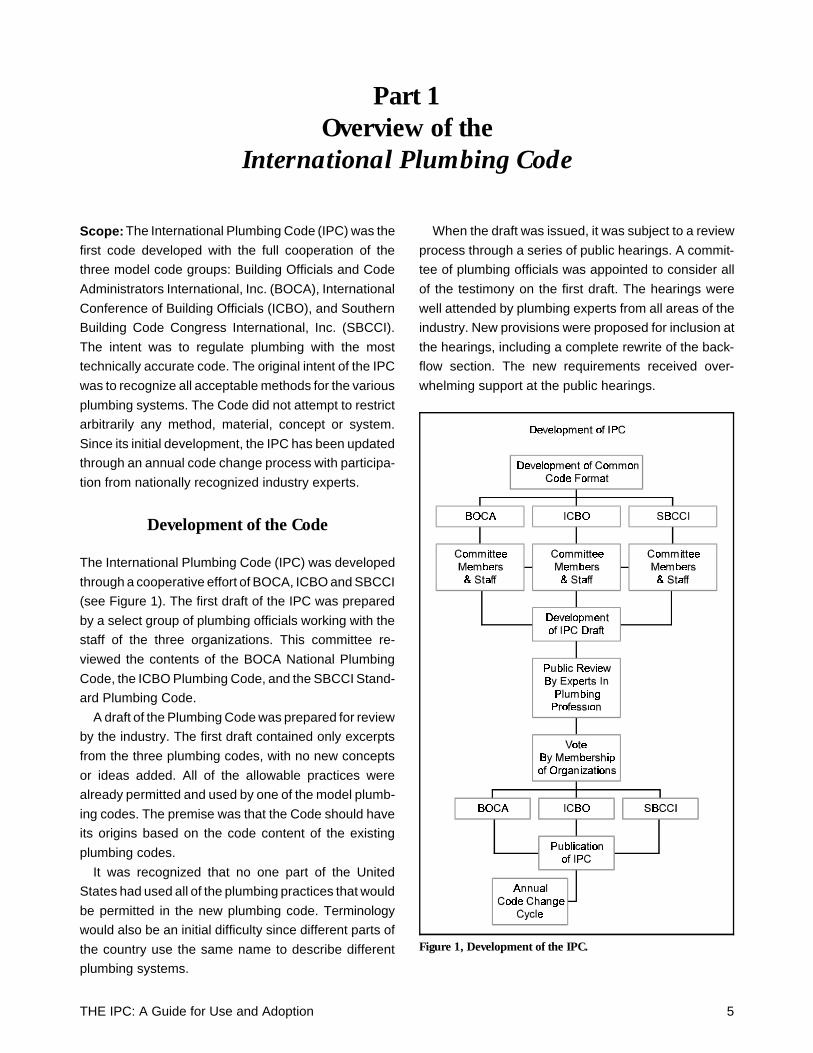
The International Plumbing Code (IPC) was developed
through a cooperative effort of BOCA, ICBO and SBCCI
(see Figure 1). The first draft of the IPC was prepared
by a select group of plumbing officials working with the
staff of the three organizations. This committee re-
viewed the contents of the BOCA National Plumbing
Code, the ICBO Plumbing Code, and the SBCCI Stand-
ard Plumbing Code.
A draft of the Plumbing Code was prepared for review
by the industry. The first draft contained only excerpts
from the three plumbing codes, with no new concepts
or ideas added. All of the allowable practices were
already permitted and used by one of the model plumb-
ing codes. The premise was that the Code should have
its origins based on the code content of the existing
plumbing codes.
It was recognized that no one part of the United
States had used all of the plumbing practices that would
be permitted in the new plumbing code. Terminology
would also be an initial difficulty since different parts of
the country use the same name to describe different
plumbing systems.
When the draft was issued, it was subject to a review
process through a series of public hearings. A commit-
tee of plumbing officials was appointed to consider all
of the testimony on the first draft. The hearings were
well attended by plumbing experts from all areas of the
industry. New provisions were proposed for inclusion at
the hearings, including a complete rewrite of the back-
flow section. The new requirements received over-
whelming support at the public hearings.
Figure 1, Development of the IPC.
THE IPC: A Guide for Use and Adoption 5
After modifying the draft to include the acceptable
changes based on testimony at the public hearings, the
document was forwarded to the membership of BOCA,
ICBO, and SBCCI. The three organizations voted unan-
imously to accept the new code as a replacement
document for their organizations’ plumbing code. In
1995, the first edition of the International Plumbing
Code was published by the International Code Council,
Inc.
Recognition of New Technology
The original committee that drafted the IPC developed
a philosophy based on acceptance of new technology
including new materials and products, as well as new
methods of installation.
While the acceptance of new technology was para-
mount to the IPC, any new idea, concept or material
must be substantiated with technical documentation
and reviewed through the open code change process.
Code Change Process
The IPC has an annual code change cycle for the review
of all new proposals, which is open and available to
everyone. The ICC accepts code change proposals
submitted before the deadline date, with no limitations
placed on the submittal of code changes. Every code
change is reviewed by the staffs of the three model code
groups to address any administrative concerns. This
provides every proponent of a code change with the
best opportunity of being considered favorably.
The code changes are published in a document for
distribution to any interested party. A public hearing is
scheduled for discussion by the proponents and oppo-
nents of each code change. The hearings are con-
ducted before the ICC Plumbing Code Change
Committee, a select group of plumbing professionals
appointed by the sponsoring organizations: BOCA,
ICBO and SBCCI. The committee is made up of plumb-
ing inspectors, plumbing engineers, labor repre-
sentatives and representatives of testing laboratories.
After hearing public testimony, the committee votes
to recommend either approval, approval with modifica-
tion, or disapproval of the code change. The results of
the committee are published with reasons for every
action taken.
The recommendations of the committee can be chal-
lenged during the second series of public hearings
where any challenged code change is open for discus-
sion. The vote at the second hearing is by the voting
membership of BOCA, ICBO and SBCCI. The member-
ship can either agree or disagree with the committee’s
recommendation. A two-thirds majority of those voting
is required to overturn the committee’s recommenda-
tion and approve a code change.
The approved code changes are published in the
supplement to, or the new edition of, the IPC.
Administration and Enforcement
Chapter 1 of the IPC follows the guidelines established
by the legal community for the regulation of a construc-
tion code. The IPC is consistent with the recommenda-
tions of Legal Aspects of Code Administration.1 The
administration requirements in the IPC recognize that
once adopted by a jurisdiction, the code becomes a
legal document. The administration and enforcement
become the responsibility of the local jurisdiction. This
is the philosophy regarding the adoption of any model
code.
Alternative Approval
Section 105 of the IPC includes the requirements for
alternative approval. This section, often considered the
most powerful section of the code, follows the guide-
lines of the Federal Trade Commission for permitting
the acceptance of new technology. It permits the code
official to accept any alternative material, method, or
equipment that may not be recognized directly in the
code.
The IPC is unique in specifying the requirements for
alternative engineered design in the approval section.
These provisions are consistent with the various state
engineering and architectural registration acts. A regis-
tered design professional is permitted to design any
plumbing system provided that he or she has adequate
technical documentation and testing to justify the alter-
native design. The alternative engineered design sec-
tion was originally developed by Bernie McCarty, P.E.,
Past President of the American Society of Plumbing
Engineers (ASPE). Mr. McCarty submitted the code text
6 THE IPC: A Guide for Use and Adoption
on behalf of ASPE, in support of the Society’s position
regarding engineering design.
Consistent with Federal Guidelines
The IPC was developed consistent with federal guide-
lines regarding seismic protection and floodproofing.
The seismic requirements in the IPC are consistent with
the recommendations of the National Earthquake Haz-
ards Reduction Program (NEHRP). The IPC references
the building code for specific regulations relating to the
location of the building.
The floodproofing requirements in the IPC were de-
veloped through a contract with the Federal Emergency
Management Agency (FEMA). FEMA requested that
references be located throughout the Code to address
the necessary floodproofing requirements.
Referenced Standards
The IPC relies on references to nationally developed
consensus standards. To assist the code user, the IPC
directly references the appropriate standard throughout
the body of the code. The complete list of the referenced
standards appears in Chapter 14, listed in order of the
promulgating organization.
The ICC developed a criterion for the acceptance of
referenced standards. To ensure fairness, the stand-
ards are required to be developed by the consensus
process.
The standards are also required to be written in
mandatory language without permissive or subjective
text, allowing the standard to be a legally enforceable
document. If there is any permissive text in a standard,
it raises the issue of enforceability and who makes the
decision regarding the permissive requirement.
All standards are reviewed for adherence to the ICC
policy.
THE IPC: A Guide for Use and Adoption 7

8 THE IPC: A Guide for Use and Adoption
Part 2Fixture Requirements
Scope: Chapter 4 of the IPC regulates the installation of
plumbing fixtures. One of the key elements in this chapter
is the table specifying the minimum number of plumbing
fixtures required based on building occupancy. Quite
often, fixture tables are perceived to be arbitrarily devel-
oped without significant technical basis. The IPC table is
based on various studies and is intended to provide equal
access to fixtures. It contains specific requirements for
handicapped-accessible plumbing fixtures and coordi-
nates with the building codes and Fair Housing Act in
specifying requirements for accessible dwelling units.
Special requirements for each type of fixture are specified
in detail with references to appropriate requirements in
other sections of the Code.
Minimum Number of Fixtures Required(Table 403.1)
Table 403.1 of the IPC specifies the minimum number of
plumbing fixtures required for every building occupancy.
The minimum fixture requirements are based on both the
number of building occupants and the occupancy classi-
fication. To avoid confusion in determining the minimum
number of fixtures, the table has been converted to
values that are consistent with the building code occu-
pant load tables.
Number of Occupants
The occupant load of a building, as determined by the
building code, is based on the means of egress require-
ments. The means of egress occupant does not typically
relate to the normal building occupancy, with the excep-
tion of assembly-type buildings. For example, in a factory
and industrial building, the normal occupancy is approxi-
mately 10 to 15 percent of the means of egress occupant
load. In a mercantile building, during heavy business
hours, the normal occupancy is approximately 25 percent
of the means of egress occupant load.
In assembly buildings, the occupancy and means of
egress occupant load are often the same. For example, a
sold-out theater performance will have an occupancy
equal to the means of egress occupant load.
Table 403.1 has been adjusted to reflect the normal
occupant load anticipated for the building. Rather
than changing the means of egress occupant load,
the table adjusted the number of fixtures required.
Hence, the IPC table is very accurate since it is
directly related to the referenced building codes.
Potty Parity
Around 1980, it was recognized that plumbing codes
were providing an injustice to the female population
by requiring an inordinate amount of plumbing fix-
tures for the male population. This prompted a re-
sponse that was referred to as “potty parity.” The
inequity resulted from plumbing codes specifying a
minimum number of water closets, as well as a mini-
mum number of urinals, for the male population. The
men’s room could end up with twice as many fixtures
used for the human elimination process as the
women’s room.
It was also recognized that when evaluating as-
sembly buildings with large occupancies, the waiting
period for the female population far exceeded any
waiting time incurred by the male population. Studies
were performed by Dr. Sandra Rawls at the University
of Virginia,2 Stevens Institute of Technology,3 the
National Restaurant Association, and the ASPE Re-
search Foundation. These studies are reflected in
Table 403.1 of the IPC.
The studies consistently showed that the time
required for a woman to use a toilet room was twice
as long as the time required for a man to use the
facilities. When the timing is related to the defecation
process, the time required for the male population
was more than twice as long as the female popula-
tion. When the values were averaged, the time re-
quired for the male and female population was
approximately equal.
THE IPC: A Guide for Use and Adoption 9
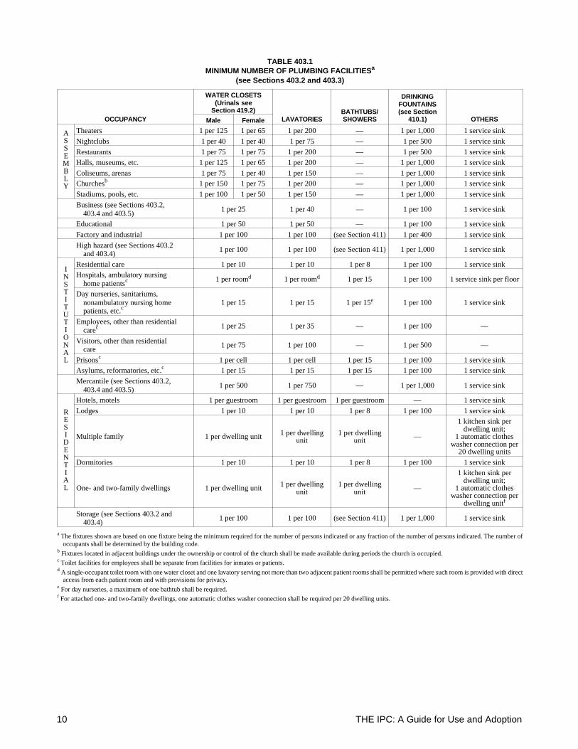
TABLE 403.1MINIMUM NUMBER OF PLUMBING FACILITIESa
(see Sections 403.2 and 403.3)
OCCUPANCY
WATER CLOSETS(Urinals see
Section 419.2)LAVATORIES
BATHTUBS/SHOWERS
DRINKINGFOUNTAINS(see Section
410.1) OTHERSMale Female
ASSEMBLY
Theaters 1 per 125 1 per 65 1 per 200 — 1 per 1,000 1 service sink
Nightclubs 1 per 40 1 per 40 1 per 75 — 1 per 500 1 service sink
Restaurants 1 per 75 1 per 75 1 per 200 — 1 per 500 1 service sinkHalls, museums, etc. 1 per 125 1 per 65 1 per 200 — 1 per 1,000 1 service sink
Coliseums, arenas 1 per 75 1 per 40 1 per 150 — 1 per 1,000 1 service sinkChurchesb 1 per 150 1 per 75 1 per 200 — 1 per 1,000 1 service sink
Stadiums, pools, etc. 1 per 100 1 per 50 1 per 150 — 1 per 1,000 1 service sink
Business (see Sections 403.2, 403.4 and 403.5)
1 per 25 1 per 40 — 1 per 100 1 service sink
Educational 1 per 50 1 per 50 — 1 per 100 1 service sink
Factory and industrial 1 per 100 1 per 100 (see Section 411) 1 per 400 1 service sink
High hazard (see Sections 403.2 and 403.4)
1 per 100 1 per 100 (see Section 411) 1 per 1,000 1 service sink
INSTITUTIONAL
Residential care 1 per 10 1 per 10 1 per 8 1 per 100 1 service sinkHospitals, ambulatory nursing home patientsc 1 per roomd 1 per roomd 1 per 15 1 per 100 1 service sink per floor
Day nurseries, sanitariums, nonambulatory nursing home patients, etc.c
1 per 15 1 per 15 1 per 15e 1 per 100 1 service sink
Employees, other than residential carec 1 per 25 1 per 35 — 1 per 100 —
Visitors, other than residential care
1 per 75 1 per 100 — 1 per 500 —
Prisonsc 1 per cell 1 per cell 1 per 15 1 per 100 1 service sinkAsylums, reformatories, etc.c 1 per 15 1 per 15 1 per 15 1 per 100 1 service sink
Mercantile (see Sections 403.2, 403.4 and 403.5)
1 per 500 1 per 750 — 1 per 1,000 1 service sink
RESIDENTIAL
Hotels, motels 1 per guestroom 1 per guestroom 1 per guestroom — 1 service sink
Lodges 1 per 10 1 per 10 1 per 8 1 per 100 1 service sink
Multiple family 1 per dwelling unit 1 per dwellingunit
1 per dwellingunit —
1 kitchen sink perdwelling unit;
1 automatic clotheswasher connection per
20 dwelling units
Dormitories 1 per 10 1 per 10 1 per 8 1 per 100 1 service sink
One- and two-family dwellings 1 per dwelling unit 1 per dwellingunit
1 per dwellingunit —
1 kitchen sink perdwelling unit;
1 automatic clotheswasher connection per
dwelling unitf
Storage (see Sections 403.2 and 403.4)
1 per 100 1 per 100 (see Section 411) 1 per 1,000 1 service sink
a The fixtures shown are based on one fixture being the minimum required for the number of persons indicated or any fraction of the number of persons indicated. The number ofoccupants shall be determined by the building code.
b Fixtures located in adjacent buildings under the ownership or control of the church shall be made available during periods the church is occupied.c Toilet facilities for employees shall be separate from facilities for inmates or patients.d A single-occupant toilet room with one water closet and one lavatory serving not more than two adjacent patient rooms shall be permitted where such room is provided with direct
access from each patient room and with provisions for privacy.e For day nurseries, a maximum of one bathtub shall be required.f For attached one- and two-family dwellings, one automatic clothes washer connection shall be required per 20 dwelling units.
10 THE IPC: A Guide for Use and Adoption
The problem with using the average value is that it is
deceiving for a large population in an assembly building
that has a high demand for use of the plumbing fixtures.
This occurs in theaters during intermission or at football
stadiums during halftime.
In developing code requirements, the studies used the
most demanding time factors to evaluate the waiting time
required. Hence, the urination process was analyzed for
determining minimum number of fixtures. If the female
population requires twice as long to complete the urina-
tion process, they would need twice as many fixtures to
have the same waiting period as the male population.
Thus, Table 403.1 in the Code reflects requirements for
twice as many water closets and urinals in the ladies’ room
when compared to the men’s room. While the number of
fixtures required will not eliminate waiting time during
heavy use periods, it will result in equal waiting periods
for both the men and the women.
Studies by the National Restaurant Association indi-
cated that “potty parity” was not required for restaurants
or nightclubs. For these types of occupancies, there is
rarely an instantaneous demand on the fixture usage. It
is uncommon for a waiting line to appear in restaurants
or nightclubs. As a result, the average time factor for
fixture use can be applied, resulting in an equal distribu-
tion of the number of plumbing fixtures.
Urinal as Substitute Fixture(See also Section 419.2)
To prevent the inequality of fixtures from occurring in the
future, the requirement for a urinal to be a mandatary
fixture was removed from the code. This was necessary
for smaller toilet rooms that were designed for one fixture.
If only one water closet is provided in the women’s room,
then only one water closet should be provided in the
men’s room.
The urinal is permitted to be substituted for a maximum
of 50 percent of the required number of water closets. This
value for substitution is based on the urination process
accounting for more than half of the toilet room usage.
Hence, when two or more water closets are required for
the men’s room, the designer or building owner can
substitute with urinals.
Basis forMinimum Fixture Requirements
The fixture requirements for assembly buildings with
large occupancies are based on permitting between
one-quarter and one-third of the population to use the
facilities during a major break. The numbers differ
based on the anticipated break time. For example, the
halftime at a football game lasts between 12 to 15
minutes while the intermission at a theater will last
between 15 to 25 minutes. The resulting values in the
table attempt to adjust the fixture usage based on
length of the anticipated heavy use period.
The requirements for restaurants and nightclubs
are based on a study by the National Restaurant
Association, which determined that nightclubs re-
quired almost twice as many plumbing fixtures be-
cause of the consumption of alcoholic beverages.
Factory and industrial complexes had their fixture
values determined based on one of the first contracts
with GM employees. They had a constant complaint
that there was inadequate time for using plumbing
fixtures during the breaks on the assembly line. The
contract specified that there had to be a minimum
number of water closets and urinals. The number
always cited for this contract was 1 water closet for
every 15 employees. This allowed everyone an op-
portunity to use the fixtures during the break. The
values have remained the same with the adjustment
for means of egress occupant load.
For prisons and dormitories, fixture studies by the
military were utilized. The military distinguished be-
tween highly regimented and partially regimented
societies. In prison, there is a high level of discipline
similar to a highly regimented military facility. For
dormitories and lodges, there is less regimentation,
resulting in the need for additional plumbing fixtures.
The lightest usage of plumbing fixtures occurs in
mercantile establishments where the general popu-
lation has a low demand for fixture use. The table
takes this into consideration. Various studies have
shown the values to be too demanding; however,
those studies are based on moderate use of covered
mall buildings. During periods of heavy use, the popu-
lation of the covered malls increases, placing a
greater demand on the plumbing fixtures.
THE IPC: A Guide for Use and Adoption 11
The International Code Council has recognized the
importance of continually reviewing the requirements for
the minimum number of plumbing fixtures. At the current
time, an ad-hoc committee of industry professionals is
studying the code requirements.
Accessible Plumbing Fixtures(Section 404)
One of the perplexing requirements in any plumbing code
is the method for regulating the requirements for handi-
capped-accessible plumbing fixtures. The IPC takes a
direct approach by including all of the necessary require-
ments for the design, installation, and enforcement of
accessible plumbing fixtures. The IPC directly references
CABO/ANSI A117.1, which regulates accessible plumb-
ing fixture requirements.
In addition to referencing the standard, the IPC speci-
fies the minimum number of fixtures required to be acces-
sible. While the standard supplies requirements for
providing accessible fixtures, the standard does not spec-
ify which fixtures are required to be accessible. This clarity
is provided in the IPC.
The accessible requirements are also coordinated with
the building code, which identifies the requirements for
accessibility for various buildings. This includes Type A
dwelling units which are required to be completely acces-
sible for persons with physical disabilities.
Type B Dwelling Unit Accessibility(Sections 404.2 and 404.3)
The IPC is the only model plumbing code to include
specific requirements for Type B dwelling units. Type B
dwelling units are designed to be readily adaptable to
handicap access. The requirements have been coordi-
nated with the Fair Housing Act.4
The IPC specifies the clear space requirements for a
kitchen, kitchen sink and the appliances. Additional re-
quirements specify the clear space and access require-
ments for the water closets, lavatories and bathtubs in the
dwelling unit. For accessible dwelling units, the code also
references CABO/ANSI A117.1.
Without the guidance in the plumbing code, the de-
signer, contractor, and inspector would have to search the
provisions in the federal law. The IPC codifies these
requirements to ensure compliance with the Fair
Housing Act.
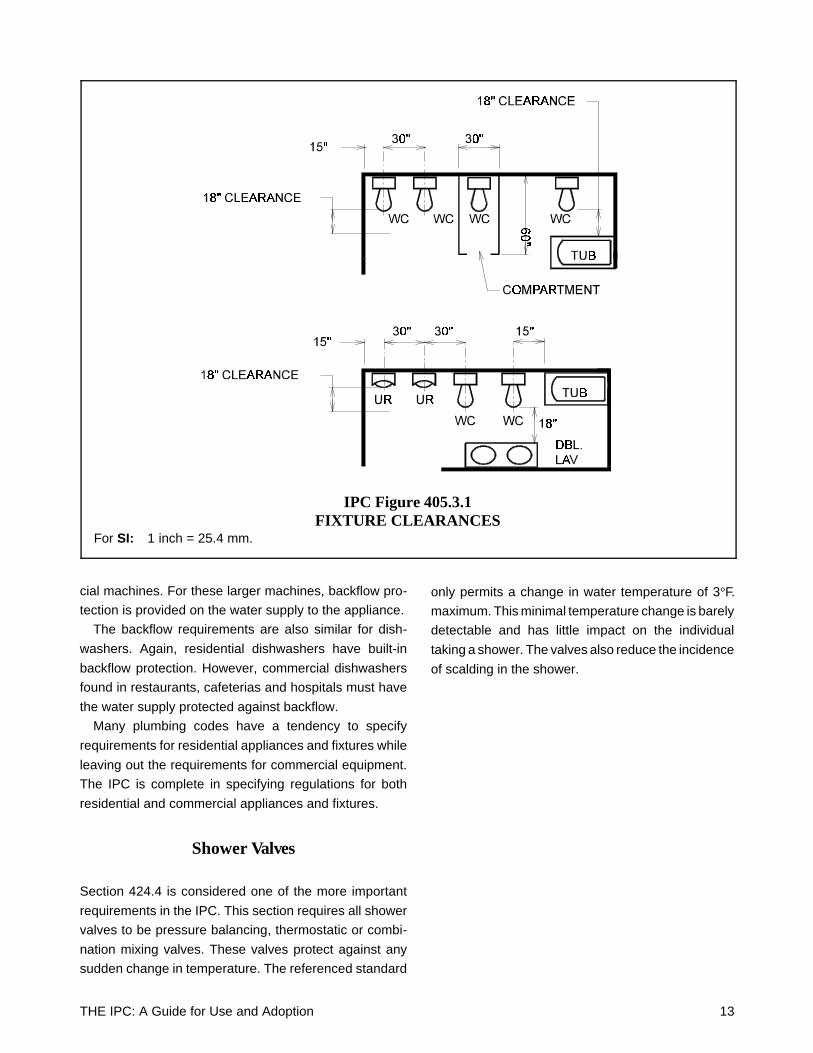
Installation of Fixtures(Section 405)
The IPC regulates the spacing of plumbing fixtures to
provide both comfort and social privacy. Figure
405.3.1 in the Code identifies the minimum spacing
requirements for various plumbing fixtures.
The spacing requirements are based on the results
of a study conducted at Cornell University, published
in a book entitled, The Bathroom.5 Prof. Alexander
Kira headed a study that completely analyzed the use
of the various plumbing fixtures. The study concluded
that adequate spacing was required between fixtures
in public toilet rooms to help facilitate the user. The
public needs privacy and space to avoid direct body
contact with other users of fixtures.
The spacing for urinals reflects dimensions that are
typically not followed in other plumbing codes. A
30-inch spacing prevents direct body contact from the
user of the adjacent urinal. If a 24-inch spacing is
provided, the result will be direct contact with the user
of the adjacent fixture.
The study at Cornell was also used to determine
the minimum size of a shower. The shower must
accommodate the movement of the individual to allow
the cleansing of the lower extremities.
Individual Fixture Requirements(Section 406 through 425)
The IPC specifies minimum code requirements for
each plumbing fixture. The individual requirements
are designed to address the full range of use for each
fixture. The Code often references other sections to
guide the user to the appropriate code sections.
An example would be the backflow requirements
for fixtures and appliances. Section 406.2 requires
automatic clothes washers to have an integral air gap
built into the machine, or the water supply must be
protected against backflow in accordance with the
requirements of Section 608. While residential and
coin-operated automatic clothes washers have inte-
gral air gaps, this is not true for many large commer-
12 THE IPC: A Guide for Use and Adoption
cial machines. For these larger machines, backflow pro-
tection is provided on the water supply to the appliance.
The backflow requirements are also similar for dish-
washers. Again, residential dishwashers have built-in
backflow protection. However, commercial dishwashers
found in restaurants, cafeterias and hospitals must have
the water supply protected against backflow.
Many plumbing codes have a tendency to specify
requirements for residential appliances and fixtures while
leaving out the requirements for commercial equipment.
The IPC is complete in specifying regulations for both
residential and commercial appliances and fixtures.
Shower Valves
Section 424.4 is considered one of the more important
requirements in the IPC. This section requires all shower
valves to be pressure balancing, thermostatic or combi-
nation mixing valves. These valves protect against any
sudden change in temperature. The referenced standard
only permits a change in water temperature of 3°F.
maximum. This minimal temperature change is barely
detectable and has little impact on the individual
taking a shower. The valves also reduce the incidence
of scalding in the shower.
IPC Figure 405.3.1FIXTURE CLEARANCES
For SI: 1 inch = 25.4 mm.
THE IPC: A Guide for Use and Adoption 13

14 THE IPC: A Guide for Use and Adoption
Part 3Water Piping Systems
Scope: The IPC regulates water piping systems in Chap-
ter 6 and water heaters in Chapter 5. The requirements
are consistent with accepted engineering practice for the
design of water distribution systems. One of the most
important aspects of water distribution systems is the
protection against backflow. The IPC has extensive re-
quirements that maintain the highest level of protection of
the potable water system.
Piping Material (Section 605)
The acceptable piping materials for water service and
water distribution systems are listed in Tables 605.4 and
605.5. The IPC accepts all of the common water piping
materials, such as copper tubing, CPVC, galvanized
steel, cross-linked polyethylene, and PEX-AL-PEX. There
are no arbitrary restrictions or prohibitions placed on the
installation of any water piping materials.
The tables identify the acceptable materials by refer-
ence to the ASTM or CSA standard(s). The IPC relies on
these organizations for the development of acceptable
material standards. Each standard is reviewed for com-
pleteness and compliance with the ICC standards policy.
The standard must properly address all technical matters
in regulating a given material for use in a potable water
piping system.
Design Criteria for Sizing (Section 604)
Table 604.3 of the IPC specifies the minimum criteria for
the design of a water distribution system. This table is
often mistaken as being the minimum flow rates required
for the specified plumbing fixtures; however, the criteria
are only used for purposes of sizing a water distribution
system.
While the table identifies both minimum flow rates and
minimum pressures, these values are used inde-
pendently of one another. When sizing a water distribution
system, the flow rate values are used in determining the
peak demand of the system. The pressure values are the
minimum requirements for the most demanding fixture
operating under a peak demand condition. The flow
rates are similar to the values published in the ASPE
Data Book.6 The minimum pressure requirements are
consistent with the fixture requirements specified in
ANSI/ASME A112.18.17 and ANSI /ASME
A112.19.6.8 When a fixture is not listed in the table,
Section 303.2 stipulates that the manufacturer shall
establish the minimum requirements for flow rates.
Maximum Flow Rates
The federal government imposed mandatary require-
ments for plumbing fixtures as part of the legislation
for water and energy conservation. The IPC maintains
consistency with the federal legislation by specifying
the maximum flow rates (at specified pressures) in
Section 604.4 and Table 604.4. The published values
in the IPC are the same as the federal legislation.
It should be noted that one of the referenced stand-
ards, ANSI/ASME A112.18.1, requires the maximum
flow rates for lavatory faucets and kitchen sinks to be
2.2 gpm at 60 psi. This value appears to be lower than
the IPC’s (and the federal government) maximum
flow rate of 2.5 gpm at 80 psi. When a flow restrictor
is utilized to control the flow rate, a flow of 2.5 gpm at
80 psi would flow 2.2 gpm when lowered to a pressure
of 60 psi. The lower flow rate in the referenced stand-
ard would only impact faucets that use flow control
devices rather than flow restructures.
Minimum Pipe Size
Table 604.5 of the IPC specifies the minimum water
pipe size required on the supply to each fixture. The
minimum pipe sizes specified are consistent with
those specified in the ASPE Data Book.
The table has an exception for sizing individual
fixture lines in a manifold parallel distribution system.
Although this type of system is normally installed with
PEX pipe, it is also possible to have a copper tubing
manifold system.
THE IPC: A Guide for Use and Adoption 15
Bathtubs, kitchen sinks, dishwashers, showers and
one-piece water closets are permitted to have the mini-
mum supply pipe reduced one pipe diameter provided
that the maximum length of pipe is 60 feet and there is a
minimum pressure of 35 psi. The reduction in pipe size is
still within the engineering limitations for sizing a water
distribution system. If an individual water supply pipe from
a manifold has a flow rate of 2.5 gpm, 3/8-inch Type M
copper tubing would have a flow velocity of 5.04 feet per
second, 3/8-inch Type L copper tubing would have a
velocity of 5.52 feet per second, and 3/8-inch PEX tubing
would have a flow velocity of 8.3 feet per second. These
velocities are within the acceptable range for the given
piping material.
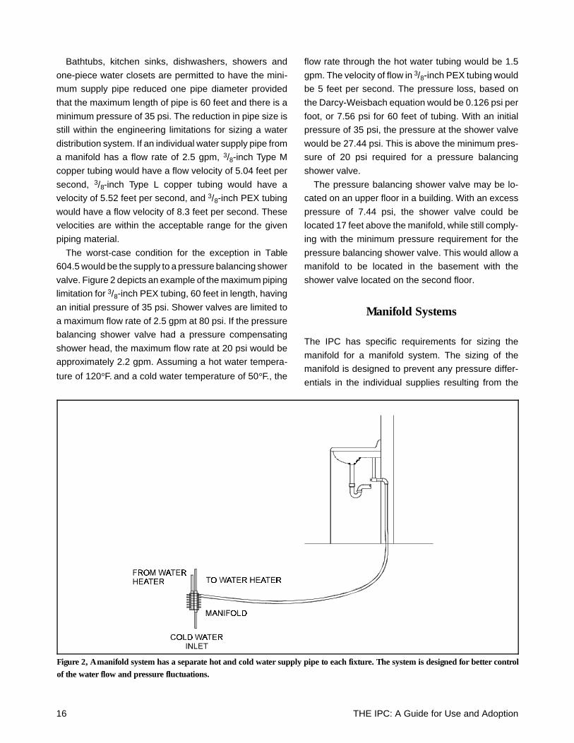
The worst-case condition for the exception in Table
604.5 would be the supply to a pressure balancing shower
valve. Figure 2 depicts an example of the maximum piping
limitation for 3/8-inch PEX tubing, 60 feet in length, having
an initial pressure of 35 psi. Shower valves are limited to
a maximum flow rate of 2.5 gpm at 80 psi. If the pressure
balancing shower valve had a pressure compensating
shower head, the maximum flow rate at 20 psi would be
approximately 2.2 gpm. Assuming a hot water tempera-
ture of 120°F. and a cold water temperature of 50°F., the
flow rate through the hot water tubing would be 1.5
gpm. The velocity of flow in 3/8-inch PEX tubing would
be 5 feet per second. The pressure loss, based on
the Darcy-Weisbach equation would be 0.126 psi per
foot, or 7.56 psi for 60 feet of tubing. With an initial
pressure of 35 psi, the pressure at the shower valve
would be 27.44 psi. This is above the minimum pres-
sure of 20 psi required for a pressure balancing
shower valve.
The pressure balancing shower valve may be lo-
cated on an upper floor in a building. With an excess
pressure of 7.44 psi, the shower valve could be
located 17 feet above the manifold, while still comply-
ing with the minimum pressure requirement for the
pressure balancing shower valve. This would allow a
manifold to be located in the basement with the
shower valve located on the second floor.
Manifold Systems
The IPC has specific requirements for sizing the
manifold for a manifold system. The sizing of the
manifold is designed to prevent any pressure differ-
entials in the individual supplies resulting from the
Figure 2, A manifold system has a separate hot and cold water supply pipe to each fixture. The system is designed for better controlof the water flow and pressure fluctuations.
16 THE IPC: A Guide for Use and Adoption
flow in adjacent lines. The balancing of the pressure by
controlling the flow in the manifold results in uninterrupted
flow at the individual fixtures.
System Sizing Requirements(Section 604.1)
The IPC requires the water distribution system to be
designed in accordance with accepted engineering prac-
tice. This provides the system designer with the flexibility
to use any approved sizing method. Some plumbing
codes choose to have a mandatory method for sizing the
water distribution system, even though the method is
inaccurate.
Many of the water pipe sizing procedures utilize the
concept of supply fixture units to determine the minimum
pipe size. This method was originally developed by Dr.
Roy B. Hunter. Hunter wrote in BMS 799 that, “the design
or piping layout and the selection of material and pipe
sizes should be delegated to an engineer experienced in
this field.” The ASPE Research Foundation called for the
abandonment of supply fixture unit sizing methods in a
report to the plumbing engineering community.10 The
fixture unit sizing method is considered out of date for
properly sizing water distribution systems. The engineer-
ing community has converted to sizing by a direct analyti-
cal method.
The IPC permits the plumbing engineer to evaluate
each water distribution system for peak demand, and size
the system accordingly. Plumbing engineers and system
designers have been employing computer programs to
size water distribution systems more accurately.
Appendix E Water Pipe Sizing Method
While the IPC does not mandate a method that must be
followed for the sizing a water distribution system, one
method of sizing is provided in Appendix E. This method
follows the precepts of Hunter’s original water pipe sizing
procedure.
The IPC recognizes that sizing methods will not always
provide accurate water pipe sizes. The sizing method in
Appendix E is provided for assistance to the code user,
especially for smaller buildings that are designed by
plumbing contractors.
Table E101B in Appendix E assigns the supply fixture
unit load for the various plumbing fixtures. This table has
been adjusted from the original values developed by
the Hunter method to account for the lower water flow
rates to water-conserving fixtures.
Appendix E includes a series of nomographs for
various water piping materials. These graphs can be
used to determine the velocity and pressure loss in a
water piping system for a given flow rate. Since the
nomographs provide information for the specific pip-
ing material, they can be utilized for any water pipe
sizing method.
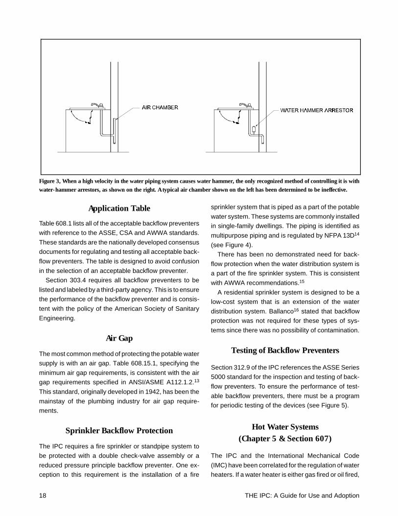
Water Hammer (Section 604.9)
The plumbing community has recognized that water
hammer in a piping system can only be controlled by
preventing the occurrence, or with the installation of
water-hammer arrestors (see Figure 3). Julius Bal-
lanco, P.E., reported that controlling velocity to pre-
vent water hammer was dependent on the type of
water piping material installed.11
Section 604.9 of the IPC follows the engineering
guidelines for water-hammer control. Some plumbing
codes require air chambers for controlling water ham-
mer. However, both Ballanco and Steele12 reported
that air chambers are ineffective in controlling water
hammer. Both individuals reported that the only viable
method for preventing the occurrence of water ham-
mer was the installation of water-hammer arrestors,
or by controlling the velocity of flow in the piping.
Backflow Protection (Section 608)
Backflow protection is considered the most important
aspect of a plumbing code. The backflow protection
requirements in the IPC have been developed with
the input of the leading backflow protection experts
in the country. This section was specially developed
for the IPC with the latest information and references
to national consensus standards.
The IPC lists the requirements for backflow protec-
tion based on the type of backflow preventers in-
tended to be installed. The Code presents every
viable option for determining the specific method of
protecting the potable water supply.
THE IPC: A Guide for Use and Adoption 17
Application Table
Table 608.1 lists all of the acceptable backflow preventers
with reference to the ASSE, CSA and AWWA standards.
These standards are the nationally developed consensus
documents for regulating and testing all acceptable back-
flow preventers. The table is designed to avoid confusion
in the selection of an acceptable backflow preventer.
Section 303.4 requires all backflow preventers to be
listed and labeled by a third-party agency. This is to ensure
the performance of the backflow preventer and is consis-
tent with the policy of the American Society of Sanitary
Engineering.
Air Gap
The most common method of protecting the potable water
supply is with an air gap. Table 608.15.1, specifying the
minimum air gap requirements, is consistent with the air
gap requirements specified in ANSI/ASME A112.1.2.13
This standard, originally developed in 1942, has been the
mainstay of the plumbing industry for air gap require-
ments.
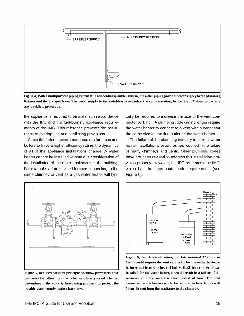
Sprinkler Backflow Protection
The IPC requires a fire sprinkler or standpipe system to
be protected with a double check-valve assembly or a
reduced pressure principle backflow preventer. One ex-
ception to this requirement is the installation of a fire
sprinkler system that is piped as a part of the potable
water system. These systems are commonly installed
in single-family dwellings. The piping is identified as
multipurpose piping and is regulated by NFPA 13D14
(see Figure 4).
There has been no demonstrated need for back-
flow protection when the water distribution system is
a part of the fire sprinkler system. This is consistent
with AWWA recommendations.15
A residential sprinkler system is designed to be a
low-cost system that is an extension of the water
distribution system. Ballanco16 stated that backflow
protection was not required for these types of sys-
tems since there was no possibility of contamination.
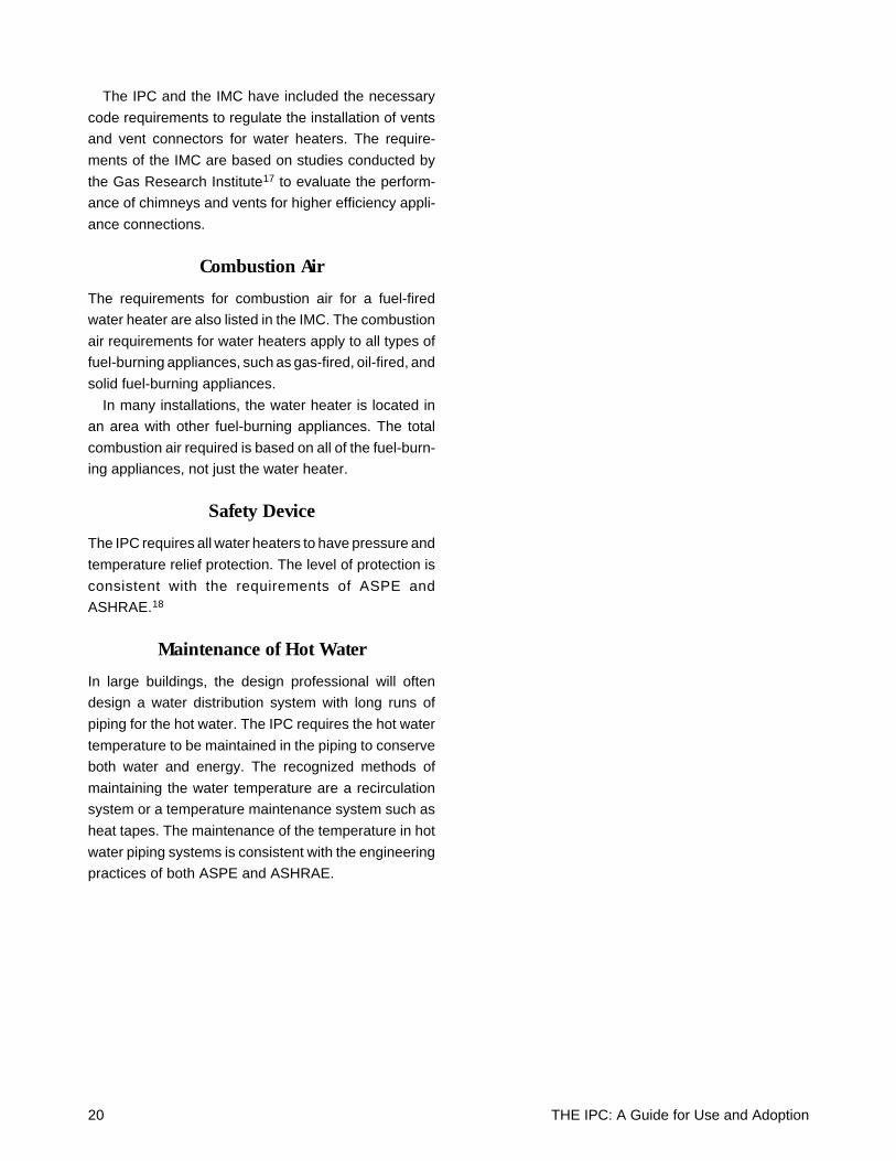
Testing of Backflow Preventers
Section 312.9 of the IPC references the ASSE Series
5000 standard for the inspection and testing of back-
flow preventers. To ensure the performance of test-
able backflow preventers, there must be a program
for periodic testing of the devices (see Figure 5).
Hot Water Systems(Chapter 5 & Section 607)
The IPC and the International Mechanical Code
(IMC) have been correlated for the regulation of water
heaters. If a water heater is either gas fired or oil fired,
Figure 3, When a high velocity in the water piping system causes water hammer, the only recognized method of controlling it is withwater-hammer arrestors, as shown on the right. A typical air chamber shown on the left has been determined to be ineffective.
18 THE IPC: A Guide for Use and Adoption
the appliance is required to be installed in accordance
with the IPC and the fuel-burning appliance require-
ments of the IMC. This reference prevents the occur-
rence of overlapping and conflicting provisions.
Since the federal government requires furnaces and
boilers to have a higher efficiency rating, the dynamics
of all of the appliance installations change. A water
heater cannot be installed without due consideration of
the installation of the other appliances in the building.
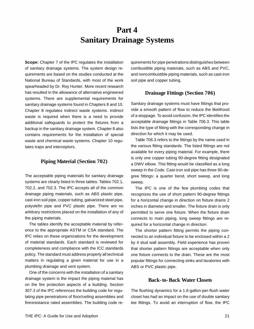
For example, a fan-assisted furnace connecting to the
same chimney or vent as a gas water heater will typi-
cally be required to increase the size of the vent con-
nector by 1 inch. A plumbing code can no longer require
the water heater to connect to a vent with a connector
the same size as the flue outlet on the water heater.
The failure of the plumbing industry to correct water
heater installation procedures has resulted in the failure
of many chimneys and vents. Other plumbing codes
have not been revised to address this installation pro-
vision properly. However, the IPC references the IMC,
which has the appropriate code requirements (see
Figure 6).
Figure 4, With a multipurpose piping system for a residential sprinkler system, the water piping provides water supply to the plumbingfixtures and the fire sprinklers. The water supply to the sprinklers is not subject to contamination; hence, the IPC does not requireany backflow protection.
Figure 5, Reduced pressure principle backflow preventers havetest cocks that allow the valve to be periodically tested. The testdetermines if the valve is functioning properly to protect thepotable water supply against backflow.
Figure 6, For this installation, the International MechanicalCode would require the vent connector for the water heater tobe increased from 3 inches to 4 inches. If a 3-inch connector wasinstalled for the water heater, it would result in a failure of themasonry chimney within a short period of time. The ventconnector for the furnace would be required to be a double wall(Type B) vent from the appliance to the chimney.
THE IPC: A Guide for Use and Adoption 19
The IPC and the IMC have included the necessary
code requirements to regulate the installation of vents
and vent connectors for water heaters. The require-
ments of the IMC are based on studies conducted by
the Gas Research Institute17 to evaluate the perform-
ance of chimneys and vents for higher efficiency appli-
ance connections.
Combustion Air
The requirements for combustion air for a fuel-fired
water heater are also listed in the IMC. The combustion
air requirements for water heaters apply to all types of
fuel-burning appliances, such as gas-fired, oil-fired, and
solid fuel-burning appliances.
In many installations, the water heater is located in
an area with other fuel-burning appliances. The total
combustion air required is based on all of the fuel-burn-
ing appliances, not just the water heater.
Safety Device
The IPC requires all water heaters to have pressure and
temperature relief protection. The level of protection is
consistent with the requirements of ASPE and
ASHRAE.18
Maintenance of Hot Water
In large buildings, the design professional will often
design a water distribution system with long runs of
piping for the hot water. The IPC requires the hot water
temperature to be maintained in the piping to conserve
both water and energy. The recognized methods of
maintaining the water temperature are a recirculation
system or a temperature maintenance system such as
heat tapes. The maintenance of the temperature in hot
water piping systems is consistent with the engineering
practices of both ASPE and ASHRAE.
20 THE IPC: A Guide for Use and Adoption
Part 4Sanitary Drainage Systems
Scope: Chapter 7 of the IPC regulates the installation
of sanitary drainage systems. The system design re-
quirements are based on the studies conducted at the
National Bureau of Standards, with most of the work
spearheaded by Dr. Roy Hunter. More recent research
has resulted in the allowance of alternative engineered
systems. There are supplemental requirements for
sanitary drainage systems found in Chapters 8 and 10.
Chapter 8 regulates indirect waste systems. Indirect
waste is required when there is a need to provide
additional safeguards to protect the fixtures from a
backup in the sanitary drainage system. Chapter 8 also
contains requirements for the installation of special
waste and chemical waste systems. Chapter 10 regu-
lates traps and interceptors.
Piping Material (Section 702)
The acceptable piping materials for sanitary drainage
systems are clearly listed in three tables: Tables 702.1,
702.2, and 702.3. The IPC accepts all of the common
drainage piping materials, such as ABS plastic pipe,
cast-iron soil pipe, copper tubing, galvanized steel pipe,
polyolefin pipe and PVC plastic pipe. There are no
arbitrary restrictions placed on the installation of any of
the piping materials.
The tables identify the acceptable material by refer-
ence to the appropriate ASTM or CSA standard. The
IPC relies on these organizations for the development
of material standards. Each standard is reviewed for
completeness and compliance with the ICC standards
policy. The standard must address properly all technical
matters in regulating a given material for use in a
plumbing drainage and vent system.
One of the concerns with the installation of a sanitary
drainage system is the impact the piping material has
on the fire protection aspects of a building. Section
307.3 of the IPC references the building code for regu-
lating pipe penetrations of floor/ceiling assemblies and
fireresistance rated assemblies. The building code re-
quirements for pipe penetrations distinguishes between
combustible piping materials, such as ABS and PVC,
and noncombustible piping materials, such as cast-iron
soil pipe and copper tubing.
Drainage Fittings (Section 706)
Sanitary drainage systems must have fittings that pro-
vide a smooth pattern of flow to reduce the likelihood
of a stoppage. To avoid confusion, the IPC identifies the
acceptable drainage fittings in Table 706.3. This table
lists the type of fitting with the corresponding change in
direction for which it may be used.
Table 706.3 refers to the fittings by the name used in
the various fitting standards. The listed fittings are not
available for every piping material. For example, there
is only one copper tubing 90-degree fitting designated
a DWV elbow. This fitting would be classified as a long
sweep in the Code. Cast-iron soil pipe has three 90-de-
gree fittings: a quarter bend, short sweep, and long
sweep.
The IPC is one of the few plumbing codes that
recognizes the use of short pattern 90-degree fittings
for a horizontal change in direction on fixture drains 2
inches in diameter and smaller. The fixture drain is only
permitted to serve one fixture. When the fixture drain
connects to main piping, long sweep fittings are re-
quired for a horizontal change in direction.
The shorter pattern fitting permits the piping con-
nected to an individual fixture to be enclosed within a 2
by 4 stud wall assembly. Field experience has proven
that shorter pattern fittings are acceptable when only
one fixture connects to the drain. These are the most
popular fittings for connecting sinks and lavatories with
ABS or PVC plastic pipe.
Back-to-Back Water Closets
The flushing dynamics for a 1.6-gallon-per-flush water
closet has had an impact on the use of double sanitary
tee fittings. To avoid an interruption of flow, the IPC
THE IPC: A Guide for Use and Adoption 21
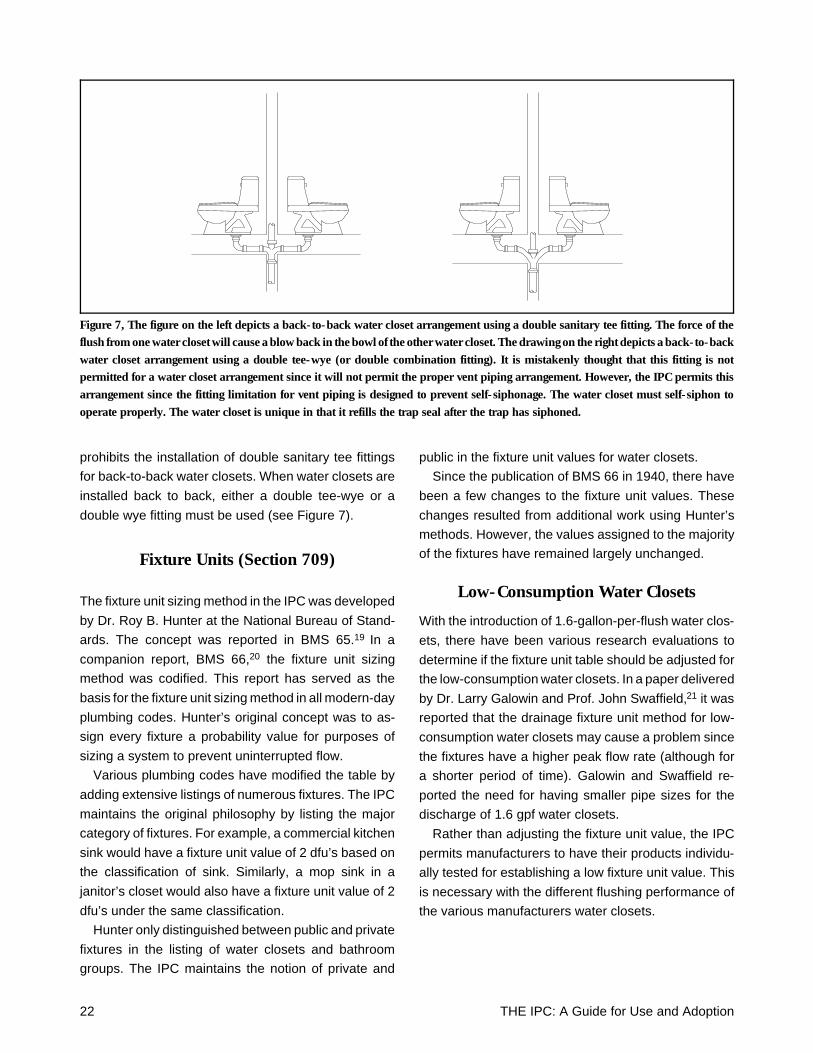
prohibits the installation of double sanitary tee fittings
for back-to-back water closets. When water closets are
installed back to back, either a double tee-wye or a
double wye fitting must be used (see Figure 7).
Fixture Units (Section 709)
The fixture unit sizing method in the IPC was developed
by Dr. Roy B. Hunter at the National Bureau of Stand-
ards. The concept was reported in BMS 65.19 In a
companion report, BMS 66,20 the fixture unit sizing
method was codified. This report has served as the
basis for the fixture unit sizing method in all modern-day
plumbing codes. Hunter’s original concept was to as-
sign every fixture a probability value for purposes of
sizing a system to prevent uninterrupted flow.
Various plumbing codes have modified the table by
adding extensive listings of numerous fixtures. The IPC
maintains the original philosophy by listing the major
category of fixtures. For example, a commercial kitchen
sink would have a fixture unit value of 2 dfu’s based on
the classification of sink. Similarly, a mop sink in a
janitor’s closet would also have a fixture unit value of 2
dfu’s under the same classification.
Hunter only distinguished between public and private
fixtures in the listing of water closets and bathroom
groups. The IPC maintains the notion of private and
public in the fixture unit values for water closets.
Since the publication of BMS 66 in 1940, there have
been a few changes to the fixture unit values. These
changes resulted from additional work using Hunter’s
methods. However, the values assigned to the majority
of the fixtures have remained largely unchanged.
Low-Consumption Water Closets
With the introduction of 1.6-gallon-per-flush water clos-
ets, there have been various research evaluations to
determine if the fixture unit table should be adjusted for
the low-consumption water closets. In a paper delivered
by Dr. Larry Galowin and Prof. John Swaffield,21 it was
reported that the drainage fixture unit method for low-
consumption water closets may cause a problem since
the fixtures have a higher peak flow rate (although for
a shorter period of time). Galowin and Swaffield re-
ported the need for having smaller pipe sizes for the
discharge of 1.6 gpf water closets.
Rather than adjusting the fixture unit value, the IPC
permits manufacturers to have their products individu-
ally tested for establishing a low fixture unit value. This
is necessary with the different flushing performance of
the various manufacturers water closets.
Figure 7, The figure on the left depicts a back-to-back water closet arrangement using a double sanitary tee fitting. The force of theflush from one water closet will cause a blow back in the bowl of the other water closet. The drawing on the right depicts a back-to-backwater closet arrangement using a double tee-wye (or double combination fitting). It is mistakenly thought that this fitting is notpermitted for a water closet arrangement since it will not permit the proper vent piping arrangement. However, the IPC permits thisarrangement since the fitting limitation for vent piping is designed to prevent self-siphonage. The water closet must self-siphon tooperate properly. The water closet is unique in that it refills the trap seal after the trap has siphoned.
22 THE IPC: A Guide for Use and Adoption
3-inch Limitation for Water Closets
The IPC has no limitation on the number of water
closets permitted on a 3-inch drain. Many plumbing
codes limit the number of water closets permitted to
discharge to a 3-inch horizontal pipe to two or three.
Hunter, in BMS 65 and BMS 66, never placed any
limitation on the number of water closets on a 3-inch
drain. His sizing method was based solely on the fixture
unit values.
The limitations on 3-inch drains were placed into
plumbing codes long after Hunter’s death, in what has
been identified as a misinterpretation of his original
research. Hunter had assigned water closets two differ-
ent fixture unit values: 6 dfu’s and 10 dfu’s. When later
research lowered the fixture unit values of water closets
to 4 dfu’s for private and 6 dfu’s for public, an arbitrary
adjustment was made to 3-inch drains. A 3-inch hori-
zontal branch was limited to a discharge of 20 dfu’s. If
water closets originally had a fixture unit value of 10
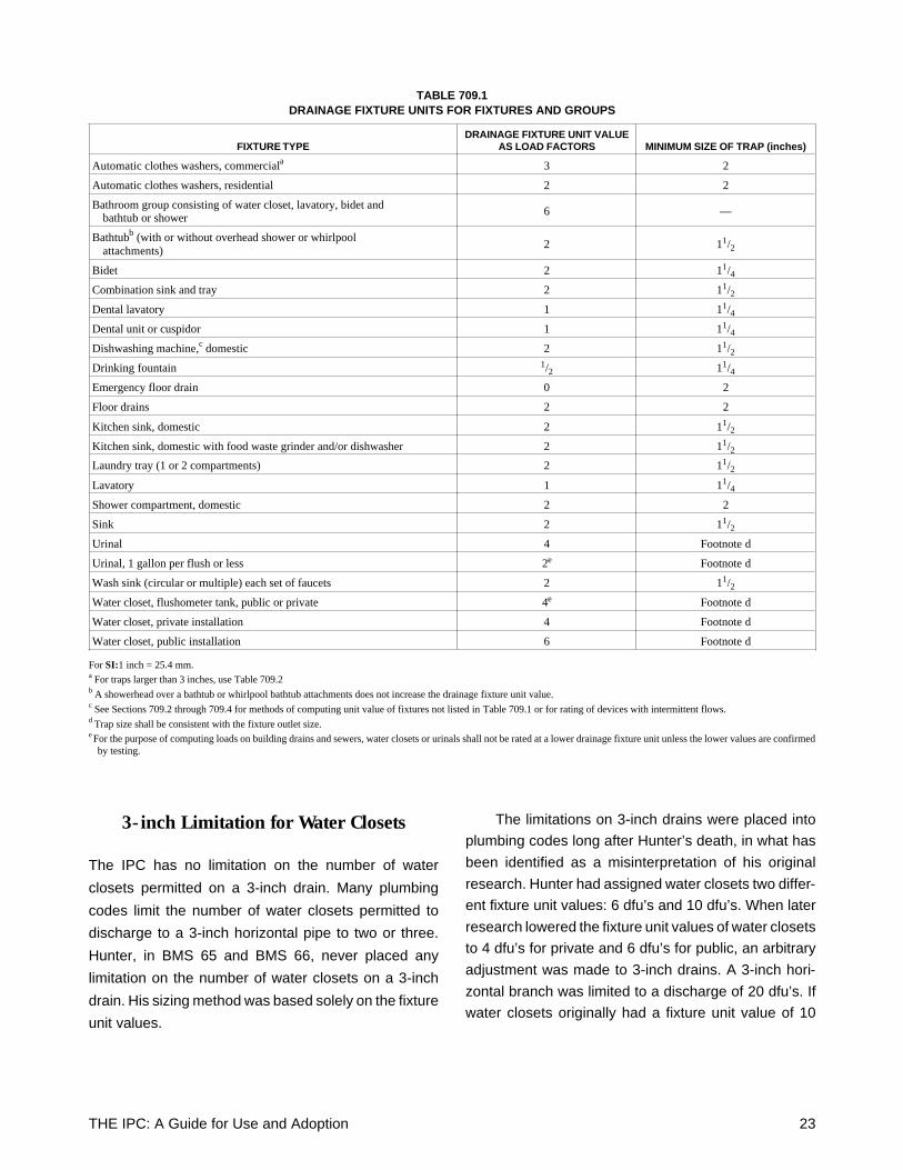
TABLE 709.1DRAINAGE FIXTURE UNITS FOR FIXTURES AND GROUPS
FIXTURE TYPEDRAINAGE FIXTURE UNIT VALUE
AS LOAD FACTORS MINIMUM SIZE OF TRAP (inches)
Automatic clothes washers, commerciala 3 2
Automatic clothes washers, residential 2 2
Bathroom group consisting of water closet, lavatory, bidet and bathtub or shower
6 —
Bathtubb (with or without overhead shower or whirlpool attachments)
2 11/2
Bidet 2 11/4
Combination sink and tray 2 11/2
Dental lavatory 1 11/4
Dental unit or cuspidor 1 11/4
Dishwashing machine,c domestic 2 11/2
Drinking fountain 1/2 11/4
Emergency floor drain 0 2
Floor drains 2 2
Kitchen sink, domestic 2 11/2
Kitchen sink, domestic with food waste grinder and/or dishwasher 2 11/2Laundry tray (1 or 2 compartments) 2 11/2
Lavatory 1 11/4
Shower compartment, domestic 2 2
Sink 2 11/2
Urinal 4 Footnote d
Urinal, 1 gallon per flush or less 2e Footnote d
Wash sink (circular or multiple) each set of faucets 2 11/2
Water closet, flushometer tank, public or private 4e Footnote d
Water closet, private installation 4 Footnote d
Water closet, public installation 6 Footnote d
For SI:1 inch = 25.4 mm.a For traps larger than 3 inches, use Table 709.2b A showerhead over a bathtub or whirlpool bathtub attachments does not increase the drainage fixture unit value.c See Sections 709.2 through 709.4 for methods of computing unit value of fixtures not listed in Table 709.1 or for rating of devices with intermittent flows.d Trap size shall be consistent with the fixture outlet size.e For the purpose of computing loads on building drains and sewers, water closets or urinals shall not be rated at a lower drainage fixture unit unless the lower values are confirmed
by testing.
THE IPC: A Guide for Use and Adoption 23
dfu’s, this would limit the number of water closets to two.
If the value of 6 dfu’s was used for water closets, that
would limit the number of water closets to three.
In a report by Galowin and Swaffield,22 and later by
Galowin, Campbell, and Swaffield,23 the arbitrary limi-
tation on the number of water closets permitted to
connect to a 3-inch drain was denounced. The IPC has
chosen to base the code requirements on the latest
technical information, hence, there is no limitation on
the number of water closets permitted to connect to a
3-inch drain. The sizing is based on fixture unit value
only.
Trap Size
The IPC lists the minimum trap size for every fixture in
the fixture unit table, Table 709.1. This is provided for
the convenience of the code user. When determining
the fixture unit value, the minimum trap size can be
determined at the same time with the same table. The
trap sizes are the minimum size permitted. A fixture is
permitted to have a larger size trap, if preferred by the
system designer.
The trap size for urinals and water closets is not listed
in the table because traps are integral with these fix-
tures and regulated by the fixture standards.
Sizing of Drainage System (Section 710)
The drainage pipe sizing method in the IPC also follows
Hunter’s methods. Hunter developed drainage pipe siz-
ing tables based on fixture unit values in his research.
The tables were modified based on follow-up research
published in NBS Monograph 31.24
The IPC has two tables for sizing drainage piping,
Tables 710.1(1) and 710.1(2). Table 710.1(1) is for
sizing building drains and building sewers. This is the
main artery of the drainage system in the building that
discharges horizontally. The sizing is based on the pipe
being a maximum of half full. The building drain and
building sewer are permitted to have the largest dis-
charge capacity since there is no interference from flow
in a vertical stack.
Table 710.1(2) is a more complex table for sizing
branches and stacks. The second column is used for
sizing the horizontal branch connecting to a stack. The
remaining columns in the table are used for sizing a
stack.
For a horizontal branch connecting to a stack, the
sizing limitation is based on the impact the branch has
on the vertical stack. Hence, the maximum fixture unit
values permitted for a given branch size are lower than
for a building drain. When the flow from a branch
transitions to a stack, there must be a smooth pattern
of flow to prevent a temporary backup of flow in the
branch. This was reported by Hunter, as well as Wyly
and Eaton. If the branch is completely loaded to half-full
flow, there can be an interruption of flow when the
drainage merges with the flow in the stack from the
upper floors.
There are two requirements for sizing a drainage
stack. There is a maximum capacity of flow permitted
from the discharge of one floor and the total discharge
into the entire stack. If the flow from a single floor is too
high, there can be an overloading of the drainage stack.
This could occur even though the loading does not
exceed the total permitted discharge for the entire stack
(see Figure 8).
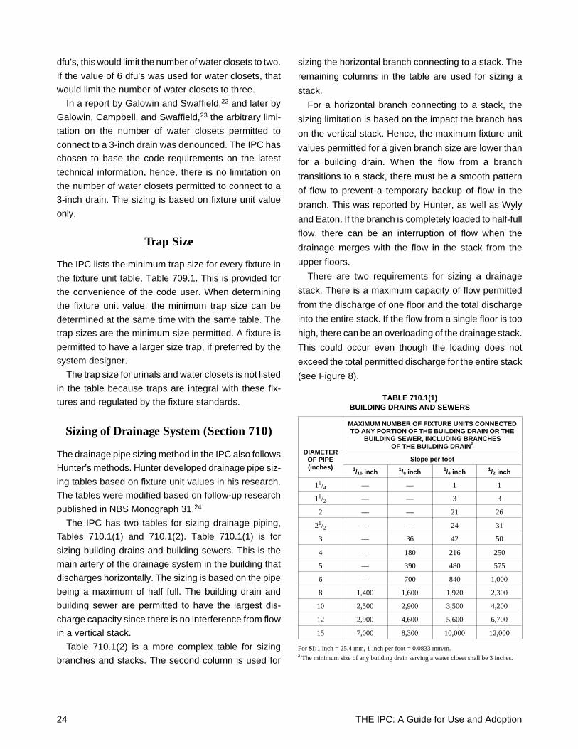
TABLE 710.1(1)BUILDING DRAINS AND SEWERS
DIAMETEROF PIPE(inches)
MAXIMUM NUMBER OF FIXTURE UNITS CONNECTEDTO ANY PORTION OF THE BUILDING DRAIN OR THE
BUILDING SEWER, INCLUDING BRANCHESOF THE BUILDING DRAINa
Slope per foot1/16 inch 1/8 inch 1/4 inch 1/2 inch
11/4 — — 1 1
11/2 — — 3 3
2 — — 21 26
21/2 — — 24 31
3 — 36 42 50
4 — 180 216 250
5 — 390 480 575
6 — 700 840 1,000
8 1,400 1,600 1,920 2,300
10 2,500 2,900 3,500 4,200
12 2,900 4,600 5,600 6,700
15 7,000 8,300 10,000 12,000
For SI:1 inch = 25.4 mm, 1 inch per foot = 0.0833 mm/m.a The minimum size of any building drain serving a water closet shall be 3 inches.
24 THE IPC: A Guide for Use and Adoption
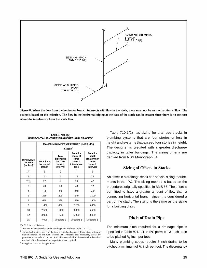
Table 710.1(2) has sizing for drainage stacks in
plumbing systems that are four stories or less in
height and systems that exceed four stories in height.
The designer is credited with a greater discharge
capacity in taller buildings. The sizing criteria are
derived from NBS Monograph 31.
Sizing of Offsets in Stacks
An offset in a drainage stack has special sizing require-
ments in the IPC. The sizing method is based on the
procedures originally specified in BMS 66. The offset is
permitted to have a greater amount of flow than a
connecting horizontal branch since it is considered a
part of the stack. The sizing is the same as the sizing
for a building drain.
Pitch of Drain Pipe
The minimum pitch required for a drainage pipe is
specified in Table 704.1. The IPC permits a 3- inch drain
to be pitched 1/8 inch per foot.
Many plumbing codes require 3-inch drains to be
pitched a minimum of 1/4 inch per foot. The discrepancy
TABLE 710.1(2)HORIZONTAL FIXTURE BRANCHES AND STACKSa
DIAMETEROF PIPE(inches)
MAXIMUM NUMBER OF FIXTURE UNITS (dfu)
Stacksb
Total for ahorizontal
branch
Totaldischargeinto onebranchinterval
Total forstack of
threebranch
intervals orless
Total forstack
greater thanthree
branchintervals
11/2 3 2 4 8
2 6 6 10 24
21/2 12 9 20 42
3 20 20 48 72
4 160 90 240 500
5 360 200 540 1,100
6 620 350 960 1,900
8 1,400 600 2,200 3,600
10 2,500 1,000 3,800 5,600
12 3,900 1,500 6,000 8,400
15 7,000 Footnote c Footnote c Footnote c
For SI:1 inch = 25.4 mm.a Does not include branches of the building drain. Refer to Table 710.1(1).b Stacks shall be sized based on the total accumulated connected load at each story or
branch interval. As the total accumulated connected load decreases, stacks arepermitted to be reduced in size. Stack diameters shall not be reduced to less thanone-half of the diameter of the largest stack size required.
c Sizing load based on design criteria.
Figure 8, When the flow from the horizontal branch intersects with flow in the stack, there must not be an interruption of flow. Thesizing is based on this criterion. The flow in the horizontal piping at the base of the stack can be greater since there is no concernabout the interference from the stack flow.
THE IPC: A Guide for Use and Adoption 25
arises from the calculated velocity of flow in a drain
using the Manning Expression.25
The minimum velocity in a horizontal drain used by
the plumbing industry is 2 feet per second. When using
a roughness factor of 0.015, the calculated velocity of
flow in a 3-inch drain pitched 1/8 inch per foot is 1.59
feet per second. When the roughness factor is changed
to 0.010, the velocity increases to 2.39 feet per second.
A roughness of 0.015 is the value that would be
assigned to a rough surface of cast iron in poor condi-
tion. A roughness of 0.010 is the value assigned to
plastic pipe and smooth interior cast iron in good con-
dition. Hence, when using the proper roughness value,
3-inch pipe can be pitched at 1/8 inch per foot and meet
the minimum velocity requirements.
It should be noted that Hunter specified a minimum
pitch of 1/8 inch per foot in BMS 66. The ASA A40.826
also permitted a pitch of 1/8 inch per foot for a 3-inch
drain.
Computerized Sizing Methods(Section 714)
The IPC allows the drainage system to be designed by
computerized method. This method of sizing is more
accurate than the method originally developed by
Hunter.
There are two computer programs recognized for
sizing drainage systems. One program was developed
at the National Bureau of Standards.27 The other pro-
gram is a complete system modeling program devel-
oped at Heriot-Watt University in Edinburgh, Scotland,
and introduced to the plumbing engineering community
at the 1996 ASPE Convention.
The Heriot-Watt University computer program per-
mits the design to simulate any condition in the drainage
system. The program permits total versatility in the
design of drainage systems.
The IPC recognizes the role computers will play in
the future design of plumbing systems. More exact
designs will result in better-performing plumbing sys-
tems.
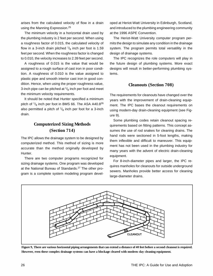
Cleanouts (Section 708)
The requirements for cleanouts have changed over the
years with the improvement of drain-cleaning equip-
ment. The IPC bases the cleanout requirements on
using modern-day drain-cleaning equipment (see Fig-
ure 9).
Some plumbing codes retain cleanout spacing re-
quirements based on fitting patterns. This concept as-
sumes the use of rod snakes for cleaning drains. The
hand rods were sectioned in 5-foot lengths, making
them inflexible and difficult to maneuver. This equip-
ment has not been used in the plumbing industry for
many years with the advent of electric drain-cleaning
equipment.
For 8-inch-diameter pipes and larger, the IPC re-
quires manholes for cleanouts for outside underground
sewers. Manholes provide better access for cleaning
large-diameter drains.
Figure 9, There are various horizontal piping arrangements that can extend a distance of 40 feet before a second cleanout is required.However, even these complex drainage systems can have a blockage cleared with modern-day cleaning equipment.
26 THE IPC: A Guide for Use and Adoption
Sewage Pumps and Ejectors(Section 712)
The IPC follows the recommendations of the Sewage
and Sump Pump Manufacturers Association for the
design and installation of sewage pumps and ejectors.
The sizing of the drain pipe from a sewage pump is
based on full flow with a minimum velocity of 2 feet per
second.
Grinder pumps that reduce the solid waste to a slurry
solution are also permitted. These pumps often result
in the use of smaller-diameter drainage pipes from the
pump.
The IPC does not arbitrarily require the installation of
dual pumping equipment for sewage sumps. The use
of this equipment is a decision for the building owner or
designer to make. The added expense of dual pumping
equipment (more than double the price because of the
required controls) does not provide any additional pro-
tection of public health or safety.
Grease Interceptors(Section 1003)
Grease interceptors are required for all restaurants,
commercial kitchens and similar food-handling estab-
lishments. The grease interceptor separates the grease
before discharging to the public sewer, thus protecting
the sewage treatment system.
The IPC is one of the few plumbing codes to permit
food waste grinders, which are the largest sources of
grease, to discharge to a grease interceptor. Some
manufacturers of grease interceptors rate their units for
the discharge of food waste grinders. A study in the
State of Wisconsin discovered that large volumes of
grease were not being intercepted in commercial kitch-
ens because the grease was flushed down the food
waste grinder during the initial washing of the dishes.
THE IPC: A Guide for Use and Adoption 27

28 THE IPC: A Guide for Use and Adoption
Part 5Venting Systems
Scope: Venting of the sanitary drainage system is one
of the most misunderstood areas of plumbing. Venting
was invented to protect the trap seal. The odors ema-
nating from the drainage system were kept out of the
building by use of a water seal trap. The trap, however,
would lose its seal. When venting was added to the
drainage system, the trap seal remained in place. The
venting requirements in the IPC are designed to main-
tain the trap seal, and thus prevent the escape of sewer
gas. There are many studies that have been performed
on venting systems. Chapter 9 of the IPC attempts to
recognize all of the viable means of venting the drain-
age system.
Material Requirements(Section 902)
Similar to the requirements for sanitary drainage piping
systems, the IPC does not place any arbitrary restric-
tions on the use of various piping materials for venting
systems. All of the viable materials are permitted to be
used for a vent system, including: cast-iron soil pipe,
copper tubing, ABS plastic pipe, PVC plastic pipe,
polyolefin plastic pipe, and galvanized steel pipe.
Concept of Venting (Section 901)
The purpose of venting is to protect the trap seal of
every fixture. The minimum trap seal required by the
IPC is 2 inches. Section 901.2 requires the venting
system to be designed to protect the trap seal from
pressure differentials in excess of 1 inch of a water
column. This assures that an adequate amount of water
will remain in the trap to prevent the escape of sewer
gas.
Section 901.2.1 establishes that every trap, and
trapped fixture, must be protected by some form of
venting. Any of the various methods of venting can be
utilized to protect the trap seal. The designer and in-
staller are granted many options for venting the traps.
Every method in the IPC has been proven to be effective
in protecting the trap seal.
Acceptable Venting Methods(Sections 907 through 913)
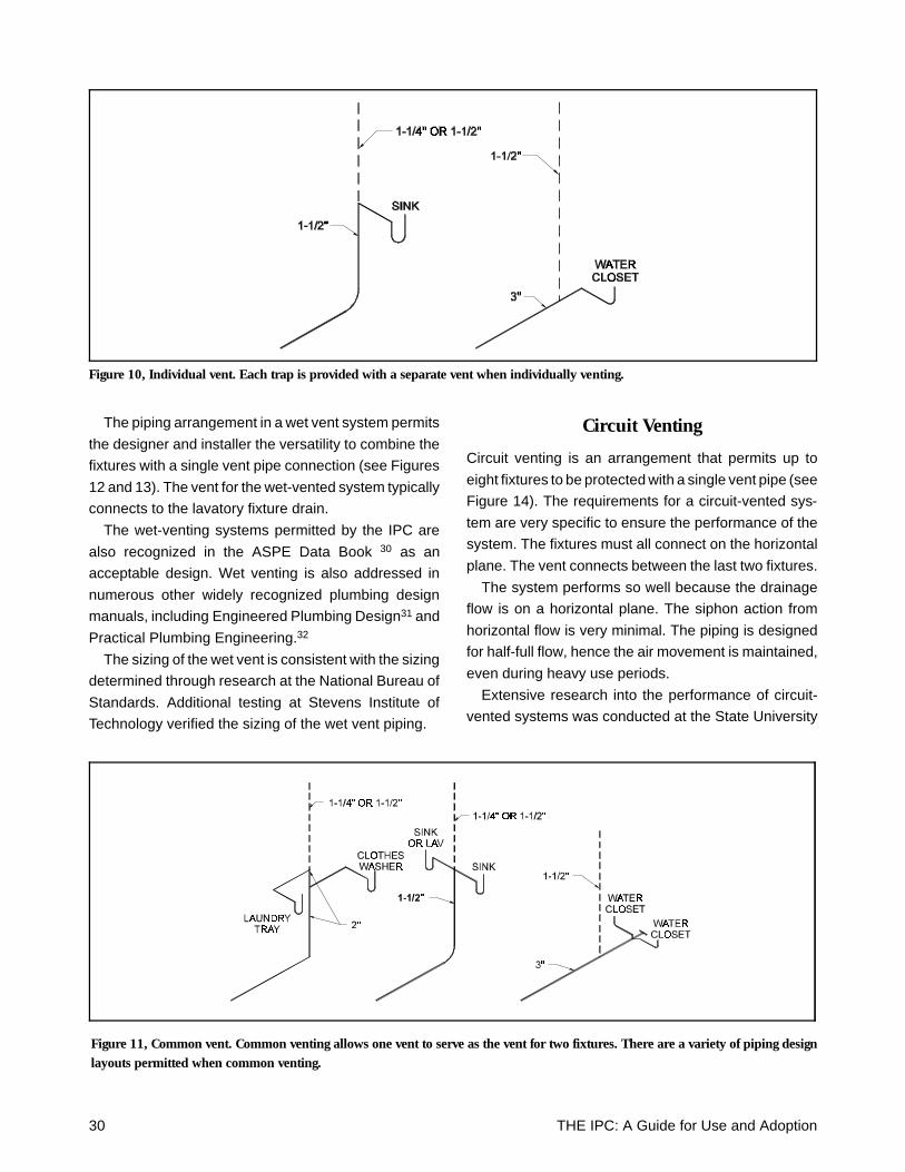
The most common form of venting is an individual vent.
A trap would have a separate vent pipe protecting the
trap seal. The vent pipe allows air to enter as well as
relieve any pressure that might be experienced in the
drainage system. This method of venting has been
included in every plumbing code since the advent of
modern indoor plumbing.
The vent only serves that one fixture trap (see Figure
10). While an individual vent is considered the easiest
method of protecting the trap, it is also a system that
results in the most extensive amount of piping.
Common Venting
Common venting is considered to be a form of individual
venting. Rather than serving a single fixture, the com-
mon vent serves two fixtures that are located in the
same general area (see Figure 11). The vent pipe can
connect to either a vertical drain serving both fixtures,
or to a horizontal drain. Another form of common vent-
ing is an offset common vent. This arrangement allows
the two fixtures being vented to connect at different
levels to a vertical drain (located on the same floor
level). Common venting was recognized by Hunter in
BMS 66.28 Offset common venting, including the piping
arrangement and sizing, was reported in BMS 119.29
Wet Venting
Wet venting is a system that combines the venting of
fixtures in a bathroom within a dwelling unit. The system
can be extended to include all of the fixtures located in
two adjacent bathrooms. Hunter first reported on wet
venting, including the concept, in BMS 66. It was further
investigated by French, Eaton, and Wiley.
THE IPC: A Guide for Use and Adoption 29
The piping arrangement in a wet vent system permits
the designer and installer the versatility to combine the
fixtures with a single vent pipe connection (see Figures
12 and 13). The vent for the wet-vented system typically
connects to the lavatory fixture drain.
The wet-venting systems permitted by the IPC are
also recognized in the ASPE Data Book 30 as an
acceptable design. Wet venting is also addressed in
numerous other widely recognized plumbing design
manuals, including Engineered Plumbing Design31 and
Practical Plumbing Engineering.32
The sizing of the wet vent is consistent with the sizing
determined through research at the National Bureau of
Standards. Additional testing at Stevens Institute of
Technology verified the sizing of the wet vent piping.
Circuit Venting
Circuit venting is an arrangement that permits up to
eight fixtures to be protected with a single vent pipe (see
Figure 14). The requirements for a circuit-vented sys-
tem are very specific to ensure the performance of the
system. The fixtures must all connect on the horizontal
plane. The vent connects between the last two fixtures.
The system performs so well because the drainage
flow is on a horizontal plane. The siphon action from
horizontal flow is very minimal. The piping is designed
for half-full flow, hence the air movement is maintained,
even during heavy use periods.
Extensive research into the performance of circuit-
vented systems was conducted at the State University
Figure 11, Common vent. Common venting allows one vent to serve as the vent for two fixtures. There are a variety of piping designlayouts permitted when common venting.
Figure 10, Individual vent. Each trap is provided with a separate vent when individually venting.
30 THE IPC: A Guide for Use and Adoption
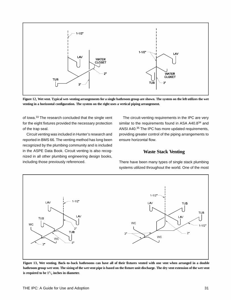
of Iowa.33 The research concluded that the single vent
for the eight fixtures provided the necessary protection
of the trap seal.
Circuit venting was included in Hunter’s research and
reported in BMS 66. The venting method has long been
recognized by the plumbing community and is included
in the ASPE Data Book. Circuit venting is also recog-
nized in all other plumbing engineering design books,
including those previously referenced.
The circuit-venting requirements in the IPC are very
similar to the requirements found in ASA A40.834 and
ANSI A40.35 The IPC has more updated requirements,
providing greater control of the piping arrangements to
ensure horizontal flow.
Waste Stack Venting
There have been many types of single stack plumbing
systems utilized throughout the world. One of the most
Figure 12, Wet vent. Typical wet-venting arrangements for a single bathroom group are shown. The system on the left utilizes the wetventing in a horizontal configuration. The system on the right uses a vertical piping arrangement.
Figure 13, Wet venting. Back-to-back bathrooms can have all of their fixtures vented with one vent when arranged in a doublebathroom group wet vent. The sizing of the wet vent pipe is based on the fixture unit discharge. The dry vent extension of the wet ventis required to be 11/2 inches in diameter.
THE IPC: A Guide for Use and Adoption 31
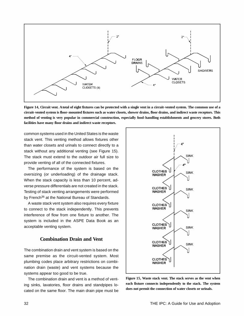
common systems used in the United States is the waste
stack vent. This venting method allows fixtures other
than water closets and urinals to connect directly to a
stack without any additional venting (see Figure 15).
The stack must extend to the outdoor air full size to
provide venting of all of the connected fixtures.
The performance of the system is based on the
oversizing (or underloading) of the drainage stack.
When the stack capacity is less than 10 percent, ad-
verse pressure differentials are not created in the stack.
Testing of stack venting arrangements were performed
by French36 at the National Bureau of Standards.
A waste stack vent system also requires every fixture
to connect to the stack independently. This prevents
interference of flow from one fixture to another. The
system is included in the ASPE Data Book as an
acceptable venting system.
Combination Drain and Vent
The combination drain and vent system is based on the
same premise as the circuit-vented system. Most
plumbing codes place arbitrary restrictions on combi-
nation drain (waste) and vent systems because the
systems appear too good to be true.
The combination drain and vent is a method of vent-
ing sinks, lavatories, floor drains and standpipes lo-
cated on the same floor. The main drain pipe must be
Figure 14, Circuit vent. A total of eight fixtures can be protected with a single vent in a circuit-vented system. The common use of acircuit-vented system is floor-mounted fixtures such as water closets, shower drains, floor drains, and indirect waste receptors. Thismethod of venting is very popular in commercial construction, especially food-handling establishments and grocery stores. Bothfacilities have many floor drains and indirect waste receptors.
Figure 15, Waste stack vent. The stack serves as the vent wheneach fixture connects independently to the stack. The systemdoes not permit the connection of water closets or urinals.
32 THE IPC: A Guide for Use and Adoption
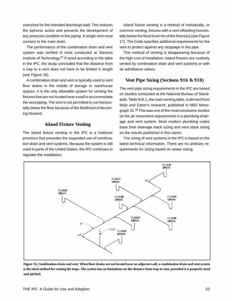
oversized for the intended discharge load. This reduces
the siphonic action and prevents the development of
any pressure condition in the piping. A single vent must
connect to the main drain.
The performance of the combination drain and vent
system was verified in tests conducted at Stevens
Institute of Technology.37 If sized according to the table
in the IPC, the study concluded that the distance from
a trap to a vent does not have to be limited in length
(see Figure 16).
A combination drain and vent is typically used to vent
floor drains in the middle of storage or warehouse
spaces. It is the only allowable system for venting the
fixtures that are not located near a wall to accommodate
the vent piping. The vent is not permitted to run horizon-
tally below the floor because of the likelihood of becom-
ing blocked.
Island Fixture Venting
The island fixture venting in the IPC is a holdover
provision that precedes the expanded use of combina-
tion drain and vent systems. Because the system is still
used in parts of the United States, the IPC continues to
regulate the installation.
Island fixture venting is a method of individually, or
common venting, fixtures with a vent offsetting horizon-
tally below the flood level rim of the fixture(s) (see Figure
17). The Code specifies additional requirements for the
vent to protect against any stoppage in the pipe.
This method of venting is disappearing because of
the high cost of installation. Island fixtures are routinely
vented by combination drain and vent systems or with
air admittance valves.
Vent Pipe Sizing (Sections 916 & 918)
The vent pipe sizing requirements in the IPC are based
on studies conducted at the National Bureau of Stand-
ards. Table 916.1, the main venting table, is derived from
Wyly and Eaton’s research, published in NBS Mono-
graph 31.38 This was one of the most conclusive studies
on the air movement requirements in a plumbing drain-
age and vent system. Most modern plumbing codes
base their drainage stack sizing and vent stack sizing
on the results published in this report.
The sizing of vent systems in the IPC is based on the
latest technical information. There are no arbitrary re-
quirements for sizing based on sewer sizing.
Figure 16, Combination drain and vent. When floor drains are not located near an adjacent wall, a combination drain and vent systemis the ideal method for venting the traps. The system has no limitations on the distance from trap to vent, provided it is properly sizedand pitched.
THE IPC: A Guide for Use and Adoption 33

Reduced Size Venting
The National Bureau of Standards followed up the
studies on vent stack air flow movement with studies on
the sizing of branch vents. This led to investigations into
reducing the size of branch vents (see Figure 18).
Orloski and Wyly published their findings of reduced
size venting in 1975.39 This study was continued with
research by Wyly and Galowin with a report issued in
1984.40
The requirements for reduced-size venting in the IPC
were written by Galowin following his research. Be-
cause of the negative response to the concept of re-
duced-size venting, Galowin added many safety factors
into the code requirements. In addition to sizing for
worst-case conditions, Galowin assumed that 50 per-
cent of the vents would be blocked. While this is a
completely unrealistic field condition, Galowin found it
necessary to respond directly to those opposed to
reduced size venting. Galowin’s interest in the recogni-
tion of reduced-size venting was directed toward future
consideration of sizing by computer modeling.
Computerized Sizing Method
The IPC recognition of the computerized drainage siz-
ing method includes the sizing of the vent system.
Hence, when computer modeling is utilized in accord-
ance with Section 714, the vent piping system is a part
of the computer modeling.
The computer modeling was developed at the Na-
tional Bureau of Standards and Heriot-Watt University.
The main authors of these studies were Galowin and
Swaffield.41,42 The computer modeling system devel-
oped by Swaffield is recognized worldwide by the
plumbing engineering community. Vent pipe sizing and
arrangements can be economically designed for the
specific installation.
Distance from Trap to Vent (Section 906)
The distance from the fixture trap to the vent connection
is limited to prevent the self-siphonage of the trap seal.
The distances are based on the study by French and
Eaton.43 It was recognized that when the branch drain
is increased in diameter, the distance from trap to vent
can be extended since the depth of flow in the drain is
Figure 17, Island fixture venting. This method of venting has beenreplaced with other methods that are more economical. The IPCcontinues to recognize this design since it protects the trap seal.
Figure 18, Reduced size venting. The individual vents can bereduced to 1/2 inch in diameter. The system performance is basedon half of the vents being completely blocked.
34 THE IPC: A Guide for Use and Adoption
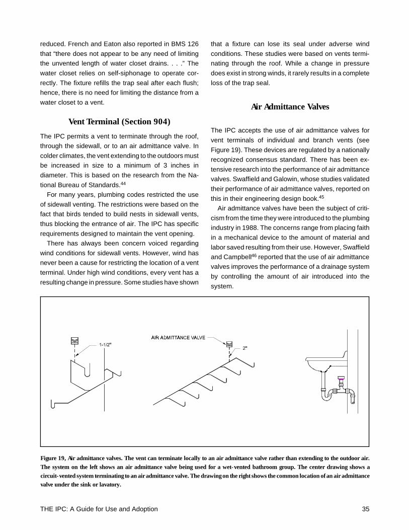
reduced. French and Eaton also reported in BMS 126
that “there does not appear to be any need of limiting
the unvented length of water closet drains. . . .” The
water closet relies on self-siphonage to operate cor-
rectly. The fixture refills the trap seal after each flush;
hence, there is no need for limiting the distance from a
water closet to a vent.
Vent Terminal (Section 904)
The IPC permits a vent to terminate through the roof,
through the sidewall, or to an air admittance valve. In
colder climates, the vent extending to the outdoors must
be increased in size to a minimum of 3 inches in
diameter. This is based on the research from the Na-
tional Bureau of Standards.44
For many years, plumbing codes restricted the use
of sidewall venting. The restrictions were based on the
fact that birds tended to build nests in sidewall vents,
thus blocking the entrance of air. The IPC has specific
requirements designed to maintain the vent opening.
There has always been concern voiced regarding
wind conditions for sidewall vents. However, wind has
never been a cause for restricting the location of a vent
terminal. Under high wind conditions, every vent has a
resulting change in pressure. Some studies have shown
that a fixture can lose its seal under adverse wind
conditions. These studies were based on vents termi-
nating through the roof. While a change in pressure
does exist in strong winds, it rarely results in a complete
loss of the trap seal.
Air Admittance Valves
The IPC accepts the use of air admittance valves for
vent terminals of individual and branch vents (see
Figure 19). These devices are regulated by a nationally
recognized consensus standard. There has been ex-
tensive research into the performance of air admittance
valves. Swaffield and Galowin, whose studies validated
their performance of air admittance valves, reported on
this in their engineering design book.45
Air admittance valves have been the subject of criti-
cism from the time they were introduced to the plumbing
industry in 1988. The concerns range from placing faith
in a mechanical device to the amount of material and
labor saved resulting from their use. However, Swaffield
and Campbell46 reported that the use of air admittance
valves improves the performance of a drainage system
by controlling the amount of air introduced into the
system.
Figure 19, Air admittance valves. The vent can terminate locally to an air admittance valve rather than extending to the outdoor air.The system on the left shows an air admittance valve being used for a wet-vented bathroom group. The center drawing shows acircuit-vented system terminating to an air admittance valve. The drawing on the right shows the common location of an air admittancevalve under the sink or lavatory.
THE IPC: A Guide for Use and Adoption 35
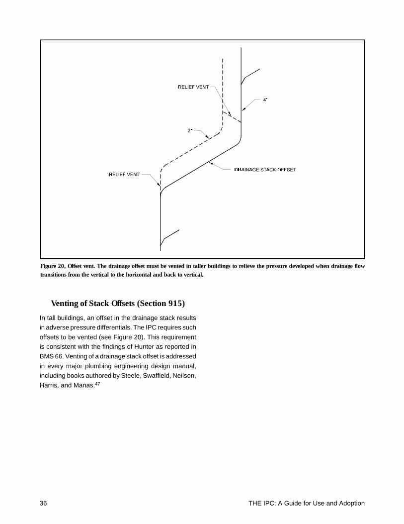
Venting of Stack Offsets (Section 915)
In tall buildings, an offset in the drainage stack results
in adverse pressure differentials. The IPC requires such
offsets to be vented (see Figure 20). This requirement
is consistent with the findings of Hunter as reported in
BMS 66. Venting of a drainage stack offset is addressed
in every major plumbing engineering design manual,
including books authored by Steele, Swaffield, Neilson,
Harris, and Manas.47
Figure 20, Offset vent. The drainage offset must be vented in taller buildings to relieve the pressure developed when drainage flowtransitions from the vertical to the horizontal and back to vertical.
36 THE IPC: A Guide for Use and Adoption
Part 6Storm Drainage Systems
Scope: Chapter 11 of the IPC regulates storm drainage
systems. The primary purpose of a storm drainage system
is to remove the rainwater from the roof surface; however,
the IPC also contains requirements intended to protect
the building from structural collapse. The storm drainage
requirements are consistent with the engineering guide-
lines of the American Society of Plumbing Engineers and
the American Society of Civil Engineers.
Primary Storm Drainage System(Section 1106)
The IPC includes sizing tables for piping systems based
on various rainfall rates. The tables are established on
sizing the storm drain for the maximum open channel
flow conditions. These are the flow rates that prevent
any pressure from being developed in the piping sys-
tems.
Vertical conductors and leaders are permitted to
have the maximum capacity of discharge as indicated
in NBS Monograph 31.48 Stacks are permitted to flow
33 percent full. This value is greater than the allowable
flow for a sanitary drainage stack since there are no
concerns for pressure differentials in the storm drain-
age systems. There are no trap seals from fixtures on
connecting floors that have to be protected from pres-
sure excursions.
For horizontal storm drains, the pipe sizing is based
on a full-flow condition. Sanitary drainage systems are
designed on a maximum of half-full flow because of
connecting fixtures and pressure differentials. Since the
storm drainage system has no intervening fixtures con-
necting, the piping system can be designed for the
maximum capacity of the drain.
Rainfall Rates
The IPC primary storm drainage system is required to be
designed for a storm of 1-hour intensity with a 100-year
return period. The rainfall rate values, published in the IPC,
are provided by the U.S. National Weather Service.
There has never been a consensus in the engineer-
ing community regarding the storm intensity for the
design of primary storm drainage systems. The IPC
uses a longer intensity storm, which lowers the rainfall
rates, with a higher return period, which increases the
rainfall rates.
The IPC supplements the rainfall rate requirements
by requiring all roofs to be designed for the maximum
amount of water ponding, with all primary roof drainage
means blocked. This requirement follows the engineer-
ing practices of the American Society of Civil Engi-
neers49 and the American Society of Plumbing
Engineers.50
Controlled Flow Systems (Section 1110)
The IPC permits the storm drainage system to be de-
signed as a controlled flow system. This system utilizes
the roof as a temporary retention area during intense
rainstorms.
The sizing of the controlled flow roof drainage system
is consistent with the engineering guidelines of ASPE,
Steele in Engineered Plumbing Design,51 and Ballanco
and Shumann in The Illustrated National Plumbing Code
Design Manual.52
Secondary Roof Drainage(Section 1107)
Secondary roof drainage is required by the IPC as an
emergency measure for protecting the roof from a
structural collapse. The secondary roof drainage must
be an independent system sized to prevent any accu-
mulation of water in excess of the amount calculated
for the roof loading. The piping for the secondary drain-
age system must be larger in size to manage cata-
strophic weather occurrences. The requirements would
only apply to roofs that can have an accumulation of
water. The secondary drainage means is permitted to
be either scuppers, openings in the parapet, or a sepa-
rate piping system.
THE IPC: A Guide for Use and Adoption 37

38 THE IPC: A Guide for Use and Adoption
Part 7Fuel Gas and Specialty Piping
Scope: Piping systems that are often designed by plumb-
ing engineers and installed by plumbing contractors in-
clude fuel gas piping, medical gas piping, and oxygen
piping systems. The International Plumbing Code recog-
nizes that these systems need to be addressed in the
plumbing code. Appropriate reference is made in the IPC
to standards and codes for regulating these systems.
Fuel Gas Piping (Chapter 12)
The requirements for fuel gas piping are located in either
the plumbing code, the mechanical code, or the fuel gas
code. The ICC decided to locate the complete fuel gas
piping requirements in the International Mechanical Code
(IMC). To assist the plumbing professional, the fuel gas
piping requirements from the IMC are duplicated in Ap-
pendix G of the IPC. This was done to avoid confusion as
to which code change committee would review proposed
code changes regarding fuel gas piping.
The ICC has recently published the first edition of the
International Fuel Gas Code. With the development of this
code, a separate code change committee will be able to
address the requirements regulating the installation of
fuel gas piping and appliances. The ICC is coordinating
the International Codes to regulate properly all building
construction requirements.
Specialty Piping (Chapter 13)
The IPC references NFPA 99C for regulating the installa-
tion of medical gas systems. This is the nationally recog-
nized consensus standard for medical gas systems. The
Joint Commission on Accreditation of Health Care Or-
ganizations, which accredits the majority of hospitals and
health care facilities in the United States, also relies on
NFPA 99C for the regulation of medical gas systems. It is
preferable to reference directly the appropriate standard,
rather than attempting to rewrite the content of the stand-
ard in the code. This allows the code to remain consistent
with the latest requirements developed by the medical
community.
For nonmedical oxygen systems, the IPC refer-
ences NFPA 50 and 51. Similar to the medical gas
requirements, these standards are the nationally rec-
ognized consensus standards for nonmedical oxygen
piping systems.
THE IPC: A Guide for Use and Adoption 39

40 THE IPC: A Guide for Use and Adoption
Endnotes
1 Legal Aspects of Code Administration, Building Officials and Code Administrators International, Inc., International Conference ofBuilding Officials, Southern Building Code Congress International, Inc. Copyright 1984.
2 Sandra K. Rawls, Ph.D., “Restroom Fixtures & Users: The Potty Parity Question,” Technical Proceedings of the ASPE 1990 Convention,American Society of Plumbing Engineers, Copyright 1991.
3 Thomas Konen, P.E., “Plumbing Fixture Requirements for Buildings,” Stevens Institute of Technology, Plumbing Engineer, October1990.
4 24 CFR Ch. 1, Final Fair Housing Accessibility Guidelines, Department of Housing and Urban Development.5 Alexander Kira, The Bathroom, Viking Press, Copyright 1966, 1976.6 SPE Data Book, “Chapter 3, Cold Water Systems,” American Society of Plumbing Engineers, Copyright 1988.7 ANSI/ASME A112.18.1-1996, “Plumbing Fixture Fittings,” American Society of Mechanical Engineers, Copyright 1996.8 ANSI/ASME A112.19.6-1995, “Hydraulic Performance Requirements for Water Closets and Urinals,” American Society of Mechanical
Engineers, Copyright 1995.9 Roy B. Hunter, “Water-Distribution Systems for Buildings,” Building Materials and Structures Report, BMS 79.10 Robert A. Wistort, P.E., CIPE, “A New Look at Determining Water Demand in Buildings: ASPE Direct Analytical Method,” Technical
Proceedings of the ASPE 1994 Convention, American Society of Plumbing Engineers, Copyright 1995.11 Julius Ballanco, P.E., “Water Hammer Control in Small Systems,” Technical Proceedings of the ASPE 1994 Convention, American
Society of Plumbing Engineers, Copyright 1995.12 Alfred Steele, P.E., Engineered Plumbing Design, Miramar Publishing Company, Copyright 1977.13 ANSI/ASME A112.1.2-1991, “Air Gaps in Plumbing Systems,” American Society of Mechanical Engineers, Copyright 1992.14 NFPA 13D-1996, Standard for the Installation of Sprinkler Systems in One- and Two-Family Dwellings and Manufactured Homes,
Copyright 1996.15 “Recommended Practice for Backflow Prevention and Cross-Connection Control,” AWWA Manual M14, American Water Works
Association, Copyright 1990.16 Julius Ballanco, P.E., The Plumbing of Residential Fire Sprinklers, Copyright 1992.17 “Interim Corrosion Test Method for Gas Furnace and Vents,” Topical Report of Research Conducted as Part of GRI’s Venting Program,
Contract GRI-5088-245-1728, February 1991.18 1995 ASHRAE Handbook, Heating, Ventilating, and Air-Conditioning Applications, American Society of Heating, Refrigerating and
Air-Conditioning Engineers, Inc., Copyright 1995.19 Roy B. Hunter, “Methods of Estimating Loads in Plumbing Systems,” Building Materials and Structures Report BMS 65, December
16, 1940.20 “Report of Subcommittee on Plumbing Central Housing Committee on Research, Design, and Construction,” Building Materials
and Structures Report BMS 66, November 22, 1940.21 Lawrence S. Galowin, Ph.D., and John A. Swaffield, Ph.D., “Effects of Low-Fixture Flows on Drainage Systems,” Edward J.
Zimmer Refresher Course, 1989, ASSE.22 Lawrence S. Galowin, Ph.D., and John A. Swaffield, Ph.D., “Big Drains, Small Drains: How Do Your Wastes Flow?” Technical
Proceedings of the ASPE 1992 Convention, American Society of Plumbing Engineers, Copyright 1993.23 Lawrence S. Galowin, Ph.D., David P. Campbell, Ph.D., and John A. Swaffield, Ph.D., “A Computer Method For Transient Solutions
With Random, Sequenced or Simultaneous Fixture Loadings,” Technical Proceedings of the 1996 ASPE Convention, American Societyof Plumbing Engineers, Copyright 1997.
THE IPC: A Guide for Use and Adoption 41
24 Robert S. Wyly and Herbert N. Eaton, “Capacities of Stacks in Sanitary Drainage Systems for Buildings,” National Bureau ofStandards Monograph 31, Issued July 3, 1961.
25 Manning Expression:
where: V = velocity in feet/secondn = coefficient of roughnessR = hydraulic radius (mean depth of flow) in feetS = hydraulic slope in feet/feet
26 National Plumbing Code, ASA A40.8, Copyright 1955.27 John A. Swaffield, Ph.D., “Application of Method of Characteristics to Model the Transport of Discrete Solids in Partially-Filled Pipe
Flow, ” NBS Building Science Series 139, February 1982.28 “Plumbing Manual, Report of Subcommittee on Plumbing Central Housing Committee on Research, Design, and Construction,”
Building Materials and Structures Report BMS 66, National Bureau of Standards, Issued November 22, 1940.29 John L. French, Herbert N. Eaton, and Robert S. Wyly, “Wet Venting of Plumbing Fixtures,” Building Materials and Structures
Report BMS 119, December 1, 1950.30 Chapter 17: Vents and Venting,” ASPE Data Book, American Society of Plumbing Engineers, Copyright 1991.31 Alfred Steele, P.E., Engineered Plumbing Design, Miramar Publishing Company, Copyright 1977.32 Cyril M. Harris, Ph.D., Practical Plumbing Engineering, McGraw-Hill, Inc., Copyright 1991.33 F. M. Dawson and D. E. Metzler, “A Report on the Investigation of Loop and Circuit Venting a Battery of Water Closets and Pedestal
Urinals,” College of Engineering, State University of Iowa, June 1953.34 National Plumbing Code, ASA A40.8, Copyright 1955.35 ANSI A40-1993, Safety Requirements for Plumbing, Copyright 1994.36 John L. French, “Stack Venting of Plumbing Fixtures,” Building Materials and Structures Report BMS 118, Issued January 23, 1950.37 Thomas P. Konen, P.E., “Performance of Unvented Branch Drains for Island Sink and Lavatories,” Report No. 110A, Stevens Institute
of Technology, March 1987.38 Robert S. Wyly and Herbert N. Eaton, “Capacities of Stacks in Sanitary Drainage Systems for Buildings,” National Bureau of
Standards Monograph 31, Issued July 3, 1961.39 M. J. Orloski and Robert S. Wyly, “Hydraulic Performance of a Full-Scale Townhouse Drain-Waste-Vent System with Reduced-Size
Vents,” National Bureau of Standards, August 1975.40 Robert S. Wyly and Lawrence S. Galowin Ph.D. , “Field Hydraulic Performance of One and Two-Story Residential Plumbing Systems
With Reduced-Size Vents,” National Bureau of Standards, May 1984.41 John A. Swaffield, Ph.D., Lawrence S. Galowin, Ph.D., and Ron Yingling, “Drain Sizing For Plumbing Codes,” Technical Proceedings
of the ASPE 1994 Convention, American Society of Plumbing Engineers, Copyright 1995.42 Lawrence S. Galowin, Ph.D., David Campbell, Ph.D., and John A. Swaffield, Ph.D., “A Computer Method for Transient Solutions
with Random, Sequenced or Simultaneous Fixture Loadings,” Technical Proceedings of the 1996 ASPE Convention, American Societyof Plumbing Engineers, Copyright 1997.
43 John L. French and Herbert N. Eaton, “Self-Siphonage of Fixture Traps,” Building Materials and Structures Report 126, IssuedOctober 15, 1951.
44 Herbert N. Eaton and Robert S. Wyly, “Frost Closure of Roof Vents in Plumbing Systems,” Building Materials and Structures Report142, October 25, 1954.
45 John A. Swaffield, Ph.D., and Lawrence S. Galowin, Ph.D., The Engineered Design of Building Drainage Systems, Ashgate Publishing,Copyright 1992.
46 John A. Swaffield, Ph.D., and David P. Campbell, Ph.D., “An Analysis of the Effect of Air Admittance Valve Installation on the DynamicResponse of Building Drainage and Vent Systems, with Particular Reference to Trap Seal Retention,” May 1993.
42 THE IPC: A Guide for Use and Adoption
47 Vincent T. Manas, P.E., National Plumbing Code Handbook, McGraw-Hill Book Co. Inc., Copyright 1957.48 Robert S. Wyly and Herbert N. Eaton, “Capacities of Stacks in Sanitary Drainage Systems for Buildings,” National Bureau of
Standards Monograph 31, July 3, 1961.49 ANSI/ASCE 7-88, Minimum Design Loads for Buildings and Other Structures, American Society of Civil Engineers, Copyright 1988.50 ASPE Data Book, American Society of Plumbing Engineers, Copyright 1990.51 Alfred Steele, P.E., Engineered Plumbing Design, Miramar Publishing Company, Copyright 1977.52 Julius Ballanco, P.E., and Eugene Shumann, The Illustrated National Plumbing Code Design Manual, Illustrated Plumbing Codes,
Copyright 1990.
THE IPC: A Guide for Use and Adoption 43

44 THE IPC: A Guide for Use and Adoption