Warning - CoolAutomation...Warning Read these Safety Precautions carefully to ensure correct...
24
Transcript of Warning - CoolAutomation...Warning Read these Safety Precautions carefully to ensure correct...


WarningRead these Safety Precautions carefully to ensure correct installation.This manual classifies precautions into WARNING and CAUTION.
WARNINGOnly qualified personnel must carry out the installation work.Ask your dealer or technical representative to install the unit.Any deficiency caused by your own installation may result in an electric shock or fire.All electrical work must be performed by a licensed technician, according to local regulations and in accordance with the instructions in the installation manual.Any lack of electric circuit or any deficiency caused by installation may result in an electric shock or fire.Do not relocate or reinstall the CoolMasterNet by yourself.Any deficiency caused by your own re-installation may result in an electric shock or fire.Make sure that all wiring is secured, that specified wires are used and that no external forces act on terminal connections or wires. Improper wiring connections or installation may produce heat and result in fire.Before touching electrical parts, turn off the unit.To dispose of this product, consult your dealer.
Failure to follow WARNING is very likely to result in such grave consequences as death or serious injury

Caution
CAUTIONDo not allow children to play with the CoolMasterNet and supervise them not to get access to the appliance.CoolMasterNet is not to be used by persons with reduced physical, sensory or mental capabilities, or lack of experience and knowledge.Do not disassemble, modify or repair the CoolMasterNet.Any deficiency caused by your modification or repair may result in an electric shock or fire.Never let the CoolMasterNet to get wet.Water can cause damage to the CoolMasterNet, and may cause an electric shock or fire.Do not use flammable materials (e.g. hairspray or insecticide) near the CoolMasterNet.Do not clean the CoolMasterNet with organic solvents such as paint thinner. The use of organic solvents may cause cracking, damaging the CoolMasterNet, causing electrical shock or fire.Do not apply AC110V or AC220V to the CoolMasterNet. The maximum voltage that can be applied to the unit directly is 24V DC.If damaged CoolMasterNet can generate heat and cause a fire.
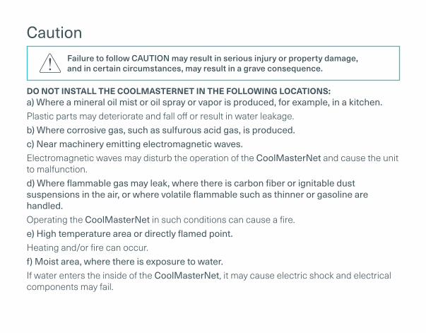
Failure to follow CAUTION may result in serious injury or property damage, and in certain circumstances, may result in a grave consequence.
Caution
DO NOT INSTALL THE COOLMASTERNET IN THE FOLLOWING LOCATIONS:a) Where a mineral oil mist or oil spray or vapor is produced, for example, in a kitchen.Plastic parts may deteriorate and fall off or result in water leakage.b) Where corrosive gas, such as sulfurous acid gas, is produced.c) Near machinery emitting electromagnetic waves.Electromagnetic waves may disturb the operation of the CoolMasterNet and cause the unit to malfunction.d) Where flammable gas may leak, where there is carbon fiber or ignitable dust suspensions in the air, or where volatile flammable such as thinner or gasoline are handled.Operating the CoolMasterNet in such conditions can cause a fire.e) High temperature area or directly flamed point.Heating and/or fire can occur.f) Moist area, where there is exposure to water.If water enters the inside of the CoolMasterNet, it may cause electric shock and electrical components may fail.
Failure to follow CAUTION may result in serious injury or property damage, and in certain circumstances, may result in a grave consequence.

What’s in the box
CoolMasterNet
1 RS232 DB9 Male to Female
cable
Optional
1 USB-Mini USB cable
1 Ethernet cable
AC Power supply adapter100V-240V 50/60hz to 12V

CoolMasterNet
L8 – HVAC Line 8 (USB Host)
Power
Power Plug
RS232 Port
L1 – HVAC Line 1
L2 – HVAC Line 2
RS485
Ethernet Port
GPIOs
L7 – HVAC Line 7
L6 – HVAC Line 6
L5 – HVAC Line 5
L4 – HVAC Line 4
USB Device Port
DIP Switches P, Q, R, S
LCD Touch Screen
L8 — HVAC Line 8 (USB Host)
Power
Power Plug
RS232 Port
L1 — HVAC Line 1
L2 — HVAC Line 2
RS485
Ethernet Port
GPIOs
L7 — HVAC Line 7
L6 — HVAC Line 6
L5 — HVAC Line 5
L4 — HVAC Line 4
USB Device Port
DIP Switches P, Q, R, S
LCD Touch Screen
1 2 3 4 5 6 7 8
15
13 12 11 1014 9
16
All Units
21 L1.101
23 L1.102
25 L1.103
25 L7.101MACADDR00001
L6 L8L5L4L3L2
192.168.0.1
DK 9/10 LG 128
All Off
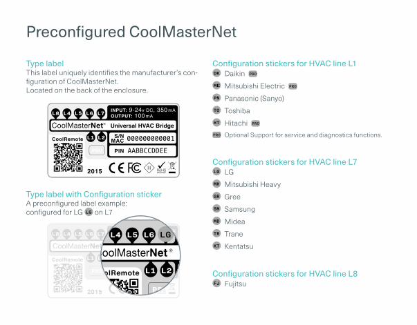
Preconfigured CoolMasterNet
Type labelThis label uniquely identifies the manufacturer’s con-figuration of CoolMasterNet. Located on the back of the enclosure.
Type label with Configuration stickerA preconfigured label example: configured for LG on L7
Configuration stickers for HVAC line L1 Daikin
Mitsubishi Electric
Panasonic (Sanyo)
Toshiba
Hitachi
Optional Support for service and diagnostics functions.
Configuration stickers for HVAC line L7 LG
Mitsubishi Heavy
Gree
Samsung
Midea
Trane
Kentatsu
Configuration stickers for HVAC line L8 Fujitsu

HVAC connectivity — on L1
HVAC Communication TerminalsConnect to the communication terminals on the HVAC equipment:
HVAC communication terminal’s names*
* For Heat Recovery systems the connection is at outdoor units only.
* Polarity is not required on the HVAC communication line.
** Centralized (group) address required.
Connecting to the line plugSecure the cables in the L1 line plug.
Plugging to the CoolMasterNetInsert the plug in to the CoolMaster L1 socket
HVAC Terminal

HVAC connectivity — on L7
HVAC Communication TerminalsConnect to the communication terminals on the:
HVAC outdoor only
HVAC indoor or outdoor
Connecting to the line plugSecure the cables in the L7 line plug. Plugging to the CoolMasterNet
Plugging to the CoolMasterNetInsert the plug in to the CoolMaster L7 socket.
HVAC Terminal

HVAC connectivity — on L8
HVAC Communication TerminalsConnect to the communication terminals on the HVAC equipment:
HVAC communication terminal’s names*
* For Heat Recovery systems the connection is at outdoor unit only.
Connecting to the Echelon adapter
Echelon U10 USB Network Interface (TP/FT-10)adapter is required for connecting to Fujitsu VRF. (Not supplied by CoolAutomation)
Connect Echelon via USB Extension cableConnect the USB Extension cable (A-Male to A-Female) to the Echelon adapter. (Not supplied by CoolAutomation).
Plug in to the CoolMasterNet L8Insert the USB cable in to the L8 USB host.
HVAC Terminal

CoolMasterNet installation complete
CoolMasterNet Unit screenAfter successful installation, units screen will show all the detected indoor units and their statuses.
Active HVAC line (DK 9/10) (Groups/Units)
Inactive HVAC line
All ON/OFF operation button
Scrollbar
Connected indoor unit with it’s address and Set-Point temperature indication.
Indoor unit operation button (on/off)
Service settings button
CoolMasterNet MAC address
CoolMasterNet IP address
CoolRemote connectivity status
Connected - Communicating
Connected - Idle
Disconnected - with error code
To download the latest firmware www.coolautomation.com/support/coolmasternetFirmware update FAQ www.coolautomation.com/support/faq/coolmasternet

Home Automation, BMS & CoolRemote
Home Automation / BMS
RS232 RS485 Ethernet
Router
CoolRemote App
Internet

Power supply
Option AAC Power supply adapter
(Included in the Box)
100V-240V AC 50/60hz
Option B
Direct DC power supply
12V-24V DC
Direct DC power supply from local electrical panel
12V DC

Option A - Manual
Go to: https://coolremote.net/register
Enter CoolMasterNet S/N number and PIN code, printed on the sticker.
Register your user-name (email) and password to remotely control & monitor all your HVAC units.
CoolRemote App
Option A - Automatic
Scan the QR code from the type label to auto fill-in all the CoolMasterNet details for CoolRemote App.
Register your user-name (email) and password to remotely control & monitor all your HVAC units.
Please connect the device to the Internet for successful registration and setup

Non-VRV HVAC system configuration on L1
Changing the dip switches , while DC voltage is present on L1, may damage the CoolMasterNet.
For Daikin/Mitsubishi Electric Non-VRV/VRF equipment, DC voltage supply by CoolMasterNet might be required for proper operation.
Make sure CoolMasterNet is disconnected from power and HVAC line.
Measure DC voltage on HVAC communication line L1
If no DC voltage. Daikin 14-16V DC, Mitsubishi 28-30V DC, change the dip switches as shown below
Turn ON the power for CoolMasterNet and connect it to HVAC line.
Mitsubishi Non-VRVDaikin Non-VRV

Appendix: Dip switches setup for VRV/VRF HVAC system on L1
HVAC systems setup on L1
Daikin
Panasonic (Sanyo)
Mitsubishi Electric
Hitachi
Toshiba
Changing HVAC System setup requires activation For more info, see http://coolautomation.com/support/coolmasternet/activation

Appendix: Dip switches setup for VRV/VRF HVAC system on L7
HVAC systems setup on L7
Mitsubishi Heavy
Midea / ChigoGree
LG
Trane Kentatsu
Samsung
Changing HVAC System setup requires activation For more info, see http://coolautomation.com/support/coolmasternet/activation

Appendix: GPIOs application
All On/Off operation by external signal
All On All Off
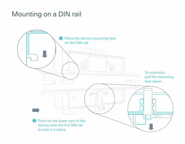
Mounting on a DIN rail
Place the device mounting feet on the DIN rail
Push on the lower part of the device onto the the DIN rail to lock it in place
To unmount, pull the mounting lock down.

Mounting on a wall
For mounting the CoolMasterNet
with wall screws, please see attached
template with 1:1 dimensions.
1:1 SCALE MOUNTING TEMPLATE FOR WALL SCREWS


1.4.
16.1
.18