
Wärtsilä 20DF Product guide. CoolingWaterSystem 9-1 9.1 Waterquality 9-1
176
WÄRTSILÄ 20DF PRODUCT GUIDE
Transcript of Wärtsilä 20DF Product guide. CoolingWaterSystem 9-1 9.1 Waterquality 9-1

WÄRTSILÄ 20DF PRODUCT GUIDE

© Copyright by WÄRTSILÄ FINLAND Oy
All rights reserved. No part of this booklet may be reproduced or copied in any form or by any means (electronic,mechanical, graphic, photocopying, recording, taping or other information retrieval systems) without the prior writtenpermission of the copyright owner.
THIS PUBLICATION IS DESIGNED TO PROVIDE AN ACCURATE AND AUTHORITATIVE INFORMATION WITHREGARD TO THE SUBJECT-MATTER COVERED AS WAS AVAILABLE AT THE TIME OF PRINTING. HOWEVER,THEPUBLICATION DEALS WITH COMPLICATED TECHNICAL MATTERS SUITED ONLY FOR SPECIALISTS IN THEAREA, AND THE DESIGN OF THE SUBJECT-PRODUCTS IS SUBJECT TO REGULAR IMPROVEMENTS,MODIFICATIONS AND CHANGES. CONSEQUENTLY, THE PUBLISHER AND COPYRIGHT OWNER OF THISPUBLICATION CAN NOT ACCEPT ANY RESPONSIBILITY OR LIABILITY FOR ANY EVENTUAL ERRORS OROMISSIONS IN THIS BOOKLET OR FOR DISCREPANCIES ARISING FROM THE FEATURES OF ANY ACTUAL ITEMIN THE RESPECTIVE PRODUCT BEING DIFFERENT FROM THOSE SHOWN IN THIS PUBLICATION. THE PUBLISHERAND COPYRIGHT OWNER SHALL UNDER NO CIRCUMSTANCES BE HELD LIABLE FOR ANY FINANCIALCONSEQUENTIAL DAMAGES OR OTHER LOSS, OR ANY OTHER DAMAGE OR INJURY, SUFFERED BY ANYPARTY MAKING USE OF THIS PUBLICATION OR THE INFORMATION CONTAINED HEREIN.

Introduction
This Product Guide provides data and system proposals for the early design phase of marineengine installations. For contracted projects specific instructions for planning the installationare always delivered. Any data and information herein is subject to revision without notice.This 3/2016 issue replaces all previous issues of the Wärtsilä 20DF Product Guides.
UpdatesPublishedIssue
Technical data updated13.09.20163/2016
Cetane index for pilot fuel oils added20.05.20162/2016
Performance data update. Other minor updates.18.03.20161/2016
Updates throughout the product guide27.02.20151/2015
Information for W20DF engines with cylinder output 185kW added19.12.20131/2013
Wärtsilä, Marine Solutions
Vaasa, September 2016
Wärtsilä 20DF Product Guide - a13 - 13 September 2016 iii
IntroductionWärtsilä 20DF Product Guide

Table of contents
1-11. Main Data and Outputs .......................................................................................................................1-11.1 Technical main data .....................................................................................................................1-11.2 Maximum continuous output .......................................................................................................1-21.3 Output limitations in gas mode ....................................................................................................1-41.4 Reference conditions ...................................................................................................................1-41.5 Operation in inclined position .....................................................................................................1-51.6 Principal dimensions and weights ...............................................................................................
2-12. Operating Ranges ................................................................................................................................2-12.1 Engine operating range ...............................................................................................................2-22.2 Loading capacity .........................................................................................................................2-62.3 Operation at low load and idling ..................................................................................................
3-13. Technical Data ......................................................................................................................................3-13.1 Wärtsilä 6L20DF ..........................................................................................................................3-43.2 Wärtsilä 8L20DF ..........................................................................................................................3-73.3 Wärtsilä 9L20DF ..........................................................................................................................
4-14. Description of the Engine ....................................................................................................................4-14.1 Definitions ....................................................................................................................................4-14.2 Main components and systems ..................................................................................................4-64.3 Overhaul intervals and expected life times ..................................................................................4-74.4 Engine storage .............................................................................................................................
5-15. Piping Design, Treatment and Installation .........................................................................................5-15.1 Pipe dimensions ..........................................................................................................................5-25.2 Trace heating ...............................................................................................................................5-25.3 Pressure class ..............................................................................................................................5-35.4 Pipe class ....................................................................................................................................5-45.5 Insulation .....................................................................................................................................5-45.6 Local gauges ...............................................................................................................................5-45.7 Cleaning procedures ...................................................................................................................5-55.8 Flexible pipe connections ............................................................................................................5-65.9 Clamping of pipes ........................................................................................................................
6-16. Fuel System ..........................................................................................................................................6-16.1 Acceptable fuel characteristics ...................................................................................................6-46.2 Operating principles ....................................................................................................................6-56.3 Fuel gas system ...........................................................................................................................
6-136.4 Fuel oil system .............................................................................................................................
7-17. Lubricating Oil System ........................................................................................................................7-17.1 Lubricating oil requirements ........................................................................................................7-37.2 Internal lubricating oil system ......................................................................................................7-57.3 External lubricating oil system .....................................................................................................7-87.4 Crankcase ventilation system ......................................................................................................7-97.5 Flushing instructions ....................................................................................................................
8-18. Compressed Air System ......................................................................................................................8-18.1 Instrument air quality ...................................................................................................................8-28.2 Internal compressed air system ..................................................................................................8-38.3 External compressed air system .................................................................................................
iv Wärtsilä 20DF Product Guide - a13 - 13 September 2016
Wärtsilä 20DF Product GuideTable of contents

9-19. Cooling Water System .........................................................................................................................9-19.1 Water quality ...............................................................................................................................9-29.2 Internal cooling water system ......................................................................................................9-49.3 External cooling water system ....................................................................................................
10-110. Combustion Air System .......................................................................................................................10-110.1 Engine room ventilation ...............................................................................................................10-210.2 Combustion air system design ....................................................................................................
11-111. Exhaust Gas System ............................................................................................................................11-111.1 Internal exhaust gas system ........................................................................................................11-211.2 Exhaust gas outlet .......................................................................................................................11-311.3 External exhaust gas system .......................................................................................................
12-112. Turbocharger Cleaning ........................................................................................................................12-112.1 Turbine cleaning system ..............................................................................................................12-112.2 Compressor cleaning system ......................................................................................................
13-113. Exhaust Emissions ...............................................................................................................................13-113.1 Dual fuel engine exhaust components ........................................................................................13-113.2 Marine exhaust emissions legislation ..........................................................................................13-513.3 Methods to reduce exhaust emissions ........................................................................................
14-114. Automation System .............................................................................................................................14-114.1 UNIC C3 .......................................................................................................................................14-714.2 Functions ....................................................................................................................................
14-1114.3 Alarm and monitoring signals ......................................................................................................14-1214.4 Electrical consumers ...................................................................................................................
15-115. Foundation ............................................................................................................................................15-115.1 Steel structure design ..................................................................................................................15-115.2 Mounting of main engines ...........................................................................................................15-615.3 Mounting of generating sets ........................................................................................................15-815.4 Flexible pipe connections ............................................................................................................
16-116. Vibration and Noise ..............................................................................................................................16-116.1 External forces and couples ........................................................................................................16-316.2 Torque variations .........................................................................................................................16-316.3 Mass moments of inertia .............................................................................................................16-316.4 Air borne noise .............................................................................................................................16-416.5 Exhaust noise ..............................................................................................................................
17-117. Power Transmission ............................................................................................................................17-117.1 Flexible coupling ..........................................................................................................................17-217.2 Torque flange ...............................................................................................................................17-217.3 Clutch ..........................................................................................................................................17-217.4 Shaft locking device ....................................................................................................................17-317.5 Power-take-off from the free end ................................................................................................17-417.6 Input data for torsional vibration calculations .............................................................................17-517.7 Turning gear .................................................................................................................................
18-118. Engine Room Layout ...........................................................................................................................18-118.1 Crankshaft distances ...................................................................................................................18-318.2 Space requirements for maintenance .........................................................................................18-318.3 Transportation and storage of spare parts and tools ..................................................................18-318.4 Required deck area for service work ...........................................................................................
19-119. Transport Dimensions and Weights ...................................................................................................19-119.1 Lifting of main engines ................................................................................................................
Wärtsilä 20DF Product Guide - a13 - 13 September 2016 v
Table of contentsWärtsilä 20DF Product Guide

19-219.2 Lifting of generating sets .............................................................................................................19-319.3 Engine components .....................................................................................................................
20-120. Product Guide Attachments ...............................................................................................................
21-121. ANNEX ...................................................................................................................................................21-121.1 Unit conversion tables .................................................................................................................21-221.2 Collection of drawing symbols used in drawings ........................................................................
vi Wärtsilä 20DF Product Guide - a13 - 13 September 2016
Wärtsilä 20DF Product GuideTable of contents

1. Main Data and Outputs
1.1 Technical main dataThe Wärtsilä 20DF is a 4-stroke, non-reversible, turbocharged and inter-cooled dual fuel enginewith direct injection of liquid fuel and indirect injection of gas fuel. The engine can be operatedin gas mode or in diesel mode.
200 mmCylinder bore ........................
280 mmStroke ...................................
8.8 l/cylPiston displacement .............
2 inlet valves and 2 exhaust valvesNumber of valves .................
6, 8 and 9 in-lineCylinder configuration ..........
clockwise, counterclockwise on requestDirection of rotation ..............
1000, 1200 rpmSpeed ...................................
9.3, 11.2 m/sMean piston speed ...............
1.2 Maximum continuous output
Table 1-1 Rating table for Wärtsilä 20DF
Generating setsMain Engines
Engine type1200 rpm1000 rpm1200 rpm
Generator[kVA]
Engine [kW]Generator[kVA]
Engine [kW]BHPkW
12701056105087614401056Wärtsilä 6L20DF
13301110115096015101110
169014081400116819201408Wärtsilä 8L20DF
178014801540128020101480
190015841580131421501584Wärtsilä 9L20DF
200016651730144022601665
The mean effective pressure Pe can be calculated using the following formula:
where:
mean effective pressure [bar]Pe =
output per cylinder [kW]P =
engine speed [r/min]n =
cylinder diameter [mm]D =
length of piston stroke [mm]L =
operating cycle (4)c =
Wärtsilä 20DF Product Guide - a13 - 13 September 2016 1-1
1. Main Data and OutputsWärtsilä 20DF Product Guide

1.3 Output limitations in gas mode
1.3.1 Output limitations due to methane number
Fig 1-1 Output limitation due to methane number
Notes:
The charge air temperature is approximately 5°C higher than the charge air coolant temperatureat rated load.
Glycol usage in cooling water according tochapter 9 "Cooling Water System".
Compensating a low methane number gas bylowering the receiver temperature below 45 °Cis not allowed.
Compensating a higher charge air temperaturethan 45 °C by a high methane number gas isnot allowed.
The dew point shall be calculated for the specificsite conditions. The minimum charge air temper-ature shall be above the dew point, otherwisecondensation will occur in the charge air cooler.
1-2 Wärtsilä 20DF Product Guide - a13 - 13 September 2016
Wärtsilä 20DF Product Guide1. Main Data and Outputs

1.3.2 Output limitations due to gas feed pressure and lowerheating value
Fig 1-2 Output limitation due to gas feed pressure and LHV
Notes:
For de-rating of output for gas temperature above5°C, contact Wärtsilä.
The graph shows the minimum Gas feed pressureat different LHV [MJ/Nm3] needed to put the en-gine in operation. The efficiency and BSEC fig-ures reported in the heat balance table are guar-anteed with min Gas feed pressure of 550kPa afor all the allowed LHV values.
The above given values for gas feed pressureare at engine inlet (before the gas filter).
No compensation (uprating) of the engine outputis allowed, neither for gas feed pressure higherthan required in the graph above nor lowerheating value above 36 MJ/Nm3.
Values are given in Nm3 is at 0 °C and 101.3kPa.
If the gas pressure is lower than required, apressure booster unit can be installed beforethe gas regulating unit to ensure adequate gaspressure. If pressure arise is not possible theengine output has to be adjusted according toabove.
Wärtsilä 20DF Product Guide - a13 - 13 September 2016 1-3
1. Main Data and OutputsWärtsilä 20DF Product Guide

1.4 Reference conditionsThe output is available within a range of ambient conditions and coolant temperatures specifiedin the chapter Technical Data. The required fuel quality for maximum output is specified in thesection Fuel characteristics. For ambient conditions or fuel qualities outside the specification,the output may have to be reduced.
The specific fuel consumption is stated in the chapter Technical Data. The statement appliesto engines operating in ambient conditions according to ISO 3046-1:2002 (E).
100 kPatotal barometric pressure
25°Cair temperature
30%relative humidity
25°Ccharge air coolant temperature
Correction factors for the fuel oil consumption in other ambient conditions are given in standardISO 3046-1:2002.
1.5 Operation in inclined positionMax. inclination angles at which the engine will operate satisfactorily.
15°● Permanent athwart ship inclinations
22.5°● Temporary athwart ship inclinations
10°● Permanent fore-and-aft inclinations
1-4 Wärtsilä 20DF Product Guide - a13 - 13 September 2016
Wärtsilä 20DF Product Guide1. Main Data and Outputs

1.6 Principal dimensions and weights
1.6.1 Main engines
Fig 1-3 Main engines (DAAF014777)
HGF2F1EDCBAEngine type
15520808246243251800169017063108W 6L20DF
15526808246243251800182417063783W 8L20DF
15529808246243251800182417064076W 9L20DF
F1 for dry sump and F2 for deep wet sump
WeightTSRPNMKIEngine type
9.4339762328971663950980718W 6L20DF
11.133986339010007381084980718W 8L20DF
11.733986339010007311084980718W 9L20DF
* Turbocharger at flywheel endDimensions in mm. Weight in tons.
Wärtsilä 20DF Product Guide - a13 - 13 September 2016 1-5
1. Main Data and OutputsWärtsilä 20DF Product Guide

1.6.2 Generating sets
Fig 1-4 Generating sets (DAAF014947A)
Weight*M*L*K*IH*G*F*E*D*C*BA*Engine type
16.91299260526812731
158017301880
1800177019202070
127014201570
895975
1025
725230045756635325W 6L20DF
20.8139027312781
17301880
180019202070
14201570
10251075
725231051007316030W 8L20DF
23.9139027812831
18802110
180020702300
15701800
10751125
725258054007316535W 9L20DF
* Dependent on generator and flexible coupling.
All dimensions in mm. Weight in metric tons with liquids.
1-6 Wärtsilä 20DF Product Guide - a13 - 13 September 2016
Wärtsilä 20DF Product Guide1. Main Data and Outputs

2. Operating Ranges
2.1 Engine operating rangeBelow nominal speed the load must be limited according to the diagrams in this chapter inorder to maintain engine operating parameters within acceptable limits. Operation in theshaded area is permitted only temporarily during transients. Minimum speed is indicated inthe diagram, but project specific limitations may apply.
2.1.1 Controllable pitch propellersAn automatic load control system is required to protect the engine from overload. The loadcontrol reduces the propeller pitch automatically, when a pre-programmed load versus speedcurve (“engine limit curve”) is exceeded, overriding the combinator curve if necessary. Engineload is determined from measured shaft power and actual engine speed. The shaft powermeter is Wärtsilä supply.
The propulsion control must also include automatic limitation of the load increase rate.Maximum loading rates can be found later in this chapter.
The propeller efficiency is highest at design pitch. It is common practice to dimension thepropeller so that the specified ship speed is attained with design pitch, nominal engine speedand 85% output in the specified loading condition. The power demand from a possible shaftgenerator or PTO must be taken into account. The 15% margin is a provision for weatherconditions and fouling of hull and propeller. An additional engine margin can be applied formost economical operation of the engine, or to have reserve power.
Wärtsilä 20DF Product Guide - a13 - 13 September 2016 2-1
2. Operating RangesWärtsilä 20DF Product Guide

2.1.1.1 Operating field for CP Propeller
Fig 2-1 Operating field for CP Propeller, rated speed 1200 rpm
Remarks: The maximum output may have to be reduced depending on gas properties andgas pressure, refer to section "Derating of output in gas mode". The permissible output willin such case be reduced with same percentage at all revolution speeds.
Restrictions for low load operation to be observed.
2.2 Loading capacityControlled load increase is essential for highly supercharged engines, because the turbochargerneeds time to accelerate before it can deliver the required amount of air. Sufficient time toachieve even temperature distribution in engine components must also be ensured. Dual fuelengines operating in gas mode require precise control of the air/fuel ratio, which makescontrolled load increase absolutely decisive for proper operation on gas fuel.
The loading ramp “preheated, normal gas” (see figures) can be used as the default loadingrate for both diesel and gas mode. If the control system has only one load increase ramp, thenthe ramp for a preheated engine must be used. The HT-water temperature in a preheatedengine must be at least 60ºC, preferably 70ºC, and the lubricating oil temperature must be atleast 40ºC.
The loading ramp “max. capacity gas” indicates the maximum capability of the engine in gasmode. Faster loading may result in alarms, knock and undesired trips to diesel. This ramp canalso be used as normal loading rate in diesel mode once the engine has attained normaloperating temperature.
The maximum loading rate “emergency diesel” is close to the maximum capability of theengine in diesel mode. It shall not be used as the normal loading rate in diesel mode.
2-2 Wärtsilä 20DF Product Guide - a13 - 13 September 2016
Wärtsilä 20DF Product Guide2. Operating Ranges

The load should always be applied gradually in normal operation. Acceptable load incrementsare smaller in gas mode than in diesel mode and also smaller at high load, which must betaken into account in applications with sudden load changes. The time between load incrementsmust be such that the maximum loading rate is not exceeded. In the case of electric powergeneration, the classification society shall be contacted at an early stage in the project regardingsystem specifications and engine loading capacity.
Electric generators must be capable of 10% overload. The maximum engine output is 110%in diesel mode and 100% in gas mode. Transfer to diesel mode takes place automatically incase of overload. Lower than specified methane number may also result in automatic transferto diesel when operating close to 100% output. Expected variations in gas fuel quality andmomentary load level must be taken into account to ensure that gas operation can bemaintained in normal operation.
2.2.1 Mechanical propulsion, controllable pitch propeller (CPP)
Fig 2-2 Maximum load increase rates for variable speed engines
The propulsion control must not permit faster load reduction than 20 s from 100% to 0%without automatic transfer to diesel first.
Wärtsilä 20DF Product Guide - a13 - 13 September 2016 2-3
2. Operating RangesWärtsilä 20DF Product Guide

2.2.2 Constant speed applications
Fig 2-3 Increasing load successively from 0 to 100% MCR
The propulsion control and the power management system must not permit faster loadreduction than 20 s from 100% to 0% without automatic transfer to diesel first.
In electric propulsion applications loading ramps are implemented both in the propulsioncontrol and in the power management system, or in the engine speed control in caseisochronous load sharing is applied. When the load sharing is based on speed droop, it mustbe taken into account that the load increase rate of a recently connected generator is the sumof the load transfer performed by the power management system and the load increaseperformed by the propulsion control.
2.2.2.1 Maximum instant load stepsThe electrical system must be designed so that tripping of breakers can be safely handled.This requires that the engines are protected from load steps exceeding their maximum loadacceptance capability. If fast load shedding is complicated to implement or undesired, theinstant load step capacity can be increased with a fast acting signal that requests transfer todiesel mode.
2-4 Wärtsilä 20DF Product Guide - a13 - 13 September 2016
Wärtsilä 20DF Product Guide2. Operating Ranges

2.2.2.1.1 Gas mode
Fig 2-4 Maximum instant load steps in % of MCR in gas mode
● Maximum step-wise load increases according to figure
● Steady-state frequency band ≤ 1.5 %
● Maximum speed drop 10 %
● Recovery time ≤ 10 s
● Time between load steps of maximum size ≥ 15 s
● Maximum step-wise load reductions: 100-75-45-0%
2.2.2.1.2 Diesel mode
● Maximum step-wise load increase 33% of MCR
● Steady-state frequency band ≤ 1.0 %
● Maximum speed drop 10 %
● Recovery time ≤ 5 s
● Time between load steps of maximum size ≥ 8 s
2.2.2.1.3 Start-up
A stand-by generator reaches nominal speed in 50-70 seconds after the start signal (checkof pilot fuel injection is always performed during a normal start).
With black-out start active nominal speed is reached in about 25 s (pilot fuel injection disabled).
The engine can be started with gas mode selected. It will then start using gas fuel as soon asthe pilot check is completed and the gas supply system is ready.
Start and stop on heavy fuel is not restricted.
Wärtsilä 20DF Product Guide - a13 - 13 September 2016 2-5
2. Operating RangesWärtsilä 20DF Product Guide

2.3 Operation at low load and idlingAbsolute idling (declutched main engine, disconnected generator):
● Maximum 10 minutes if the engine is to be stopped after the idling. 3-5 minutes idlingbefore stop is recommended.
● Maximum 6 hours if the engine is to be loaded after the idling.
● Maximum idling speed is 1000 rpm (see note).
Operation below 20 % load on HFO or below 10 % load on MDF or gas
● Maximum 100 hours continuous operation. At intervals of 100 operating hours the enginemust be loaded to minimum 70 % of the rated output for 1 hour.
Operation above 20 % load on HFO or above 10 % load on MDF or gas
● No restrictions.
NOTE
Idling is performed at 1000 rpm. For 1200 rpm engines the engine speed isincreased to 1200 rpm when synchronization is selected. In case the generatorbreaker is opened the engine automatically goes to 1000 rpm if a stop commandis not given.
2-6 Wärtsilä 20DF Product Guide - a13 - 13 September 2016
Wärtsilä 20DF Product Guide2. Operating Ranges

3. Technical Data
3.1 Wärtsilä 6L20DF
MEAE/DEAE/DE
Wärtsilä 6L20DF Dieselmode
Gasmode
Dieselmode
Gasmode
Dieselmode
Gasmode
185185160kWCylinder output
120012001000rpmEngine speed
11101110960kWEngine output
2.12.12.18MPaMean effective pressure
Tier 2Tier 3Tier 2Tier 3Tier 2Tier 3IMO compliance
Combustion air system (Note 1)
2.31.82.21.82.01.5kg/sFlow at 100% load
454545°CTemperature at turbocharger intake, max.
504550455045°CTemperature after air cooler (TE 601)
Exhaust gas system (Note 2)
2.31.82.21.81.91.5kg/sFlow at 100% load
1.71.41.71.41.51.2kg/sFlow at 75% load
1.21.11.21.11.01.0kg/sFlow at 50% load
315370330370325350°CTemperature after turbocharger at 100% load (TE517)
325400325405330400°CTemperature after turbocharger at 75% load (TE517)
325365360415360420°CTemperature after turbocharger at 50% load (TE517)
444kPaBackpressure, max.
371344370344343309mmCalculated exhaust diameter for 35 m/s
Heat balance at 100% load (Note 3)
245230250235210200kWJacket water, HT-circuit
430320410300330260kWCharge air, LT-circuit
175165175165140145kWLubricating oil, LT-circuit
505050504545kWRadiation
Fuel consumption (Note 4)
-8370-8340-8180kJ/kWhTotal energy consumption at 100% load
-8550-8720-8520kJ/kWhTotal energy consumption at 75% load
-9090-9500-9140kJ/kWhTotal energy consumption at 50% load
-8222-8189-8048kJ/kWhFuel gas consumption at 100% load
-8360-8494-8326kJ/kWhFuel gas consumption at 75% load
-8860-9212-8862kJ/kWhFuel gas consumption at 50% load
1973.51983.41953.1g/kWhFuel oil consumption at 100% load
1964.41985.31964.5g/kWhFuel oil consumption at 75% load
1985.42086.72076.4g/kWhFuel oil consumption 50% load
Fuel gas system (Note 5)
-550-550-520kPa (a)Gas pressure at engine inlet, min (PT901)
Wärtsilä 20DF Product Guide - a13 - 13 September 2016 3-1
3. Technical DataWärtsilä 20DF Product Guide

MEAE/DEAE/DE
Wärtsilä 6L20DF Dieselmode
Gasmode
Dieselmode
Gasmode
Dieselmode
Gasmode
185185160kWCylinder output
-670-670-640kPa (a)Gas pressure to Gas Valve unit, min
-0...60-0...60-0...60°CGas temperature before Gas Valve Unit
Fuel oil system
700±50700±50700±50kPaPressure before injection pumps (PT 101)
1.21.21.1m3/hFuel oil flow to engine, approx
16...24-16...24-16...24-cStHFO viscosity before the engine
1.81.81.8cStMDF viscosity, min.
140-140-140-°CMax. HFO temperature before engine (TE 101)
0.9-0.9-0.8-kg/hLeak fuel quantity (HFO), clean fuel at 100% load
4.62.34.62.33.92.0kg/hLeak fuel quantity (MDF), clean fuel at 100% load
1.8...11.01.8...11.01.8...11.0cStPilot fuel (MDF) viscosity before the engine
10...4010...4010...40kPaPilot fuel pressure at engine inlet (112)
131313kPaPilot fuel pressure drop after engine, max
Lubricating oil system
450450450kPaPressure before bearings, nom. (PT 201)
202020kPaSuction ability, including pipe loss, max.
808080kPaPriming pressure, nom. (PT 201)
666666°CTemperature before bearings, nom. (TE 201)
787878°CTemperature after engine, approx.
483434m3/hPump capacity (main), engine driven
212121m3/hPump capacity (main), electrically driven
8.6 / 10.58.6 / 10.58.6 / 10.5m3/hPriming pump capacity (50/60Hz)
0.380.380.38m³Oil volume, wet sump, nom.
222m3Oil volume in separate system oil tank
0.50.50.5g/kWhOil consumption at 100% load, approx.
726726726l/minCrankcase ventilation flow rate at full load
300300300PaCrankcase ventilation backpressure, max.
1.4...2.21.4...2.21.4...2.2lOil volume in speed governor
HT cooling water system
200 + static200 + static200 + statickPaPressure at engine, after pump, nom. (PT 401)
350500500kPaPressure at engine, after pump, max. (PT 401)
838383°CTemperature before cylinders, approx. (TE 401)
919191°CTemperature after engine, nom.
303030m3/hCapacity of engine driven pump, nom.
909090kPaPressure drop over engine, total
150 (1.5)150 (1.5)150 (1.5)kPaPressure drop in external system, max.
70...15070...15070...150kPaPressure from expansion tank
0.120.120.12m3Water volume in engine
200200200kPaDelivery head of stand-by pump
LT cooling water system
200+ static200+ static200+ statickPaPressure at engine, after pump, nom. (PT 471)
350500500kPaPressure at engine, after pump, max. (PT 471)
3-2 Wärtsilä 20DF Product Guide - a13 - 13 September 2016
Wärtsilä 20DF Product Guide3. Technical Data

MEAE/DEAE/DE
Wärtsilä 6L20DF Dieselmode
Gasmode
Dieselmode
Gasmode
Dieselmode
Gasmode
185185160kWCylinder output
383838°CTemperature before engine, max. (TE 471)
252525°CTemperature before engine, min. (TE 471)
393936m3/hCapacity of engine driven pump, nom.
303030kPaPressure drop over charge air cooler
120 (1.2)120 (1.2)120 (1.2)kPaPressure drop in external system, max.
70...15070...15070...150kPaPressure from expansion tank
200200200kPaDelivery head of stand-by pump
Starting air system
300030003000kPaPressure, nom.
300030003000kPaPressure, max.
180018001800kPaLow pressure limit in air vessels
1.21.21.2Nm3Starting air consumption, start (successful)
Notes:
At ISO 15550 conditions (ambient air temperature 25°C, LT-water 25°C) and 100% load. Flowtolerance 5%.
Note 1
At ISO 15550 conditions (ambient air temperature 25°C, LT-water 25°C). Flow tolerance 5%and temperature tolerance 15°C.
Note 2
At ISO 15550 conditions (ambient air temperature 25°C, LT-water 25°C) and 100% load. Toler-ance for cooling water heat 10%, tolerance for radiation heat 30%. Fouling factors and a marginto be taken into account when dimensioning heat exchangers.
Note 3
At ambient conditions according to ISO 15550 and receiver temperature 45 °C. Lower calorificvalue 42 700 kJ/kg for pilot fuel and 49 620 kJ/kg for gas fuel. With engine driven pumps (twocooling water pumps, one lubricating oil pump and pilot fuel pump). Tolerance 5%.
Note 4
Fuel gas pressure given at LHV = 36MJ/m³N. Required fuel gas pressure depends on fuel gasLHV and need to be increased for lower LHV's. Pressure drop in external fuel gas system tobe considered. See chapter Fuel system for further information.
Note 5
ME = Engine driving propeller, variable speed
AE = Auxiliary engine driving generator
DE = Diesel-Electric engine driving generator
Subject to revision without notice.
Wärtsilä 20DF Product Guide - a13 - 13 September 2016 3-3
3. Technical DataWärtsilä 20DF Product Guide

3.2 Wärtsilä 8L20DF
MEAE/DEAE/DE
Wärtsilä 8L20DF Dieselmode
Gasmode
Dieselmode
Gasmode
Dieselmode
Gasmode
185185160kWCylinder output
120012001000rpmEngine speed
148014801280kWEngine output
2.12.12.18MPaMean effective pressure
Tier 2Tier 3Tier 2Tier 3Tier 2Tier 3IMO compliance
Combustion air system (Note 1)
3.12.33.02.32.72.0kg/sFlow at 100% load
454545°CTemperature at turbocharger intake, max.
504550455045°CTemperature after air cooler (TE 601)
Exhaust gas system (Note 2)
3.02.43.02.42.62.0kg/sFlow at 100% load
2.31.92.31.92.01.7kg/sFlow at 75% load
1.61.51.61.51.41.3kg/sFlow at 50% load
315370330370325350°CTemperature after turbocharger at 100% load (TE517)
325400325405330400°CTemperature after turbocharger at 75% load (TE517)
325365360415360420°CTemperature after turbocharger at 50% load (TE517)
444kPaBackpressure, max.
428394428398396359mmCalculated exhaust diameter for 35 m/s
Heat balance at 100% load (Note 3)
327307333313280267kWJacket water, HT-circuit
573427547400440347kWCharge air, LT-circuit
233220233220187193kWLubricating oil, LT-circuit
676767676060kWRadiation
Fuel consumption (Note 4)
-8370-8340-8180kJ/kWhTotal energy consumption at 100% load
-8550-8720-8520kJ/kWhTotal energy consumption at 75% load
-9090-9500-9140kJ/kWhTotal energy consumption at 50% load
-8222-8189-8048kJ/kWhFuel gas consumption at 100% load
-8360-8494-8326kJ/kWhFuel gas consumption at 75% load
-8860-9212-8862kJ/kWhFuel gas consumption at 50% load
1973.51983.41953.1g/kWhFuel oil consumption at 100% load
1964.41985.31964.5g/kWhFuel oil consumption at 75% load
1985.42086.72076.4g/kWhFuel oil consumption 50% load
Fuel gas system (Note 5)
-550-550-520kPa (a)Gas pressure at engine inlet, min (PT901)
-670-670-640kPa (a)Gas pressure to Gas Valve unit, min
-0...60-0...60-0...60°CGas temperature before Gas Valve Unit
Fuel oil system
3-4 Wärtsilä 20DF Product Guide - a13 - 13 September 2016
Wärtsilä 20DF Product Guide3. Technical Data

MEAE/DEAE/DE
Wärtsilä 8L20DF Dieselmode
Gasmode
Dieselmode
Gasmode
Dieselmode
Gasmode
185185160kWCylinder output
700±50700±50700±50kPaPressure before injection pumps (PT 101)
1.61.61.4m3/hFuel oil flow to engine, approx
16...24-16...24-16...24-cStHFO viscosity before the engine
1.81.81.8cStMDF viscosity, min.
140-140-140-°CMax. HFO temperature before engine (TE 101)
1.2-1.2-1.0-kg/hLeak fuel quantity (HFO), clean fuel at 100% load
6.13.16.13.15.22.6kg/hLeak fuel quantity (MDF), clean fuel at 100% load
1.8...11.01.8...11.01.8...11.0cStPilot fuel (MDF) viscosity before the engine
10...4010...4010...40kPaPilot fuel pressure at engine inlet (112)
131313kPaPilot fuel pressure drop after engine, max
Lubricating oil system
450450450kPaPressure before bearings, nom. (PT 201)
202020kPaSuction ability, including pipe loss, max.
808080kPaPriming pressure, nom. (PT 201)
666666°CTemperature before bearings, nom. (TE 201)
787878°CTemperature after engine, approx.
644848m3/hPump capacity (main), engine driven
272727m3/hPump capacity (main), electrically driven
8.6 / 10.58.6 / 10.58.6 / 10.5m3/hPriming pump capacity (50/60Hz)
0.490.490.49m³Oil volume, wet sump, nom.
222m3Oil volume in separate system oil tank
0.50.50.5g/kWhOil consumption at 100% load, approx.
823823823l/minCrankcase ventilation flow rate at full load
300300300PaCrankcase ventilation backpressure, max.
1.4...2.21.4...2.21.4...2.2lOil volume in speed governor
HT cooling water system
200 + static200 + static200 + statickPaPressure at engine, after pump, nom. (PT 401)
350500500kPaPressure at engine, after pump, max. (PT 401)
838383°CTemperature before cylinders, approx. (TE 401)
919191°CTemperature after engine, nom.
414140m3/hCapacity of engine driven pump, nom.
909090kPaPressure drop over engine, total
150 (1.5)150 (1.5)150 (1.5)kPaPressure drop in external system, max.
70...15070...15070...150kPaPressure from expansion tank
0.150.150.15m3Water volume in engine
200200200kPaDelivery head of stand-by pump
LT cooling water system
200+ static200+ static200+ statickPaPressure at engine, after pump, nom. (PT 471)
350500500kPaPressure at engine, after pump, max. (PT 471)
383838°CTemperature before engine, max. (TE 471)
252525°CTemperature before engine, min. (TE 471)
515148m3/hCapacity of engine driven pump, nom.
303030kPaPressure drop over charge air cooler
Wärtsilä 20DF Product Guide - a13 - 13 September 2016 3-5
3. Technical DataWärtsilä 20DF Product Guide

MEAE/DEAE/DE
Wärtsilä 8L20DF Dieselmode
Gasmode
Dieselmode
Gasmode
Dieselmode
Gasmode
185185160kWCylinder output
120 (1.2)120 (1.2)120 (1.2)kPaPressure drop in external system, max.
70...15070...15070...150kPaPressure from expansion tank
200200200kPaDelivery head of stand-by pump
Starting air system
300030003000kPaPressure, nom.
300030003000kPaPressure, max.
180018001800kPaLow pressure limit in air vessels
1.21.21.2Nm3Starting air consumption, start (successful)
Notes:
At ISO 15550 conditions (ambient air temperature 25°C, LT-water 25°C) and 100% load. Flowtolerance 5%.
Note 1
At ISO 15550 conditions (ambient air temperature 25°C, LT-water 25°C). Flow tolerance 5%and temperature tolerance 15°C.
Note 2
At ISO 15550 conditions (ambient air temperature 25°C, LT-water 25°C) and 100% load. Toler-ance for cooling water heat 10%, tolerance for radiation heat 30%. Fouling factors and a marginto be taken into account when dimensioning heat exchangers.
Note 3
At ambient conditions according to ISO 15550 and receiver temperature 45 °C. Lower calorificvalue 42 700 kJ/kg for pilot fuel and 49 620 kJ/kg for gas fuel. With engine driven pumps (twocooling water pumps, one lubricating oil pump and pilot fuel pump). Tolerance 5%.
Note 4
Fuel gas pressure given at LHV = 36MJ/m³N. Required fuel gas pressure depends on fuel gasLHV and need to be increased for lower LHV's. Pressure drop in external fuel gas system tobe considered. See chapter Fuel system for further information.
Note 5
ME = Engine driving propeller, variable speed
AE = Auxiliary engine driving generator
DE = Diesel-Electric engine driving generator
Subject to revision without notice.
3-6 Wärtsilä 20DF Product Guide - a13 - 13 September 2016
Wärtsilä 20DF Product Guide3. Technical Data

3.3 Wärtsilä 9L20DF
MEAE/DEAE/DE
Wärtsilä 9L20DF Dieselmode
Gasmode
Dieselmode
Gasmode
Dieselmode
Gasmode
185185160kWCylinder output
120012001000rpmEngine speed
166516651440kWEngine output
2.12.12.18MPaMean effective pressure
Tier 2Tier 3Tier 2Tier 3Tier 2Tier 3IMO compliance
Combustion air system (Note 1)
3.52.63.32.63.02.2kg/sFlow at 100% load
454545°CTemperature at turbocharger intake, max.
504550455045°CTemperature after air cooler (TE 601)
Exhaust gas system (Note 2)
3.42.73.32.72.92.3kg/sFlow at 100% load
2.62.12.62.22.21.9kg/sFlow at 75% load
1.81.71.81.71.51.5kg/sFlow at 50% load
315370330370325350°CTemperature after turbocharger at 100% load (TE517)
325400325405330400°CTemperature after turbocharger at 75% load (TE517)
325365360415360420°CTemperature after turbocharger at 50% load (TE517)
444kPaBackpressure, max.
454419454423420382mmCalculated exhaust diameter for 35 m/s
Heat balance at 100% load (Note 3)
368345375353315300kWJacket water, HT-circuit
645480615450495390kWCharge air, LT-circuit
263248263248210218kWLubricating oil, LT-circuit
757575756868kWRadiation
Fuel consumption (Note 4)
-8370-8340-8180kJ/kWhTotal energy consumption at 100% load
-8550-8720-8520kJ/kWhTotal energy consumption at 75% load
-9090-9500-9140kJ/kWhTotal energy consumption at 50% load
-8222-8189-8048kJ/kWhFuel gas consumption at 100% load
-8360-8494-8326kJ/kWhFuel gas consumption at 75% load
-8860-9212-8862kJ/kWhFuel gas consumption at 50% load
1973.51983.41953.1g/kWhFuel oil consumption at 100% load
1964.41985.31964.5g/kWhFuel oil consumption at 75% load
1985.42086.72076.4g/kWhFuel oil consumption 50% load
Fuel gas system (Note 5)
-550-550-520kPa (a)Gas pressure at engine inlet, min (PT901)
-670-670-640kPa (a)Gas pressure to Gas Valve unit, min
-0...60-0...60-0...60°CGas temperature before Gas Valve Unit
Fuel oil system
Wärtsilä 20DF Product Guide - a13 - 13 September 2016 3-7
3. Technical DataWärtsilä 20DF Product Guide

MEAE/DEAE/DE
Wärtsilä 9L20DF Dieselmode
Gasmode
Dieselmode
Gasmode
Dieselmode
Gasmode
185185160kWCylinder output
700±50700±50700±50kPaPressure before injection pumps (PT 101)
1.81.91.6m3/hFuel oil flow to engine, approx
16...24-16...24-16...24-cStHFO viscosity before the engine
1.81.81.8cStMDF viscosity, min.
140-140-140-°CMax. HFO temperature before engine (TE 101)
1.4-1.4-1.2-kg/hLeak fuel quantity (HFO), clean fuel at 100% load
6.83.46.93.45.92.9kg/hLeak fuel quantity (MDF), clean fuel at 100% load
1.8...11.01.8...11.01.8...11.0cStPilot fuel (MDF) viscosity before the engine
10...4010...4010...40kPaPilot fuel pressure at engine inlet (112)
131313kPaPilot fuel pressure drop after engine, max
Lubricating oil system
450450450kPaPressure before bearings, nom. (PT 201)
202020kPaSuction ability, including pipe loss, max.
808080kPaPriming pressure, nom. (PT 201)
666666°CTemperature before bearings, nom. (TE 201)
787878°CTemperature after engine, approx.
644848m3/hPump capacity (main), engine driven
303030m3/hPump capacity (main), electrically driven
8.6 / 10.58.6 / 10.58.6 / 10.5m3/hPriming pump capacity (50/60Hz)
0.550.550.55m³Oil volume, wet sump, nom.
222m3Oil volume in separate system oil tank
0.50.50.5g/kWhOil consumption at 100% load, approx.
871871871l/minCrankcase ventilation flow rate at full load
300300300PaCrankcase ventilation backpressure, max.
1.4...2.21.4...2.21.4...2.2lOil volume in speed governor
HT cooling water system
200 + static200 + static200 + statickPaPressure at engine, after pump, nom. (PT 401)
350500500kPaPressure at engine, after pump, max. (PT 401)
838383°CTemperature before cylinders, approx. (TE 401)
919191°CTemperature after engine, nom.
464645m3/hCapacity of engine driven pump, nom.
909090kPaPressure drop over engine, total
150 (1.5)150 (1.5)150 (1.5)kPaPressure drop in external system, max.
70...15070...15070...150kPaPressure from expansion tank
0.160.160.16m3Water volume in engine
200200200kPaDelivery head of stand-by pump
LT cooling water system
200+ static200+ static200+ statickPaPressure at engine, after pump, nom. (PT 471)
350500500kPaPressure at engine, after pump, max. (PT 471)
383838°CTemperature before engine, max. (TE 471)
252525°CTemperature before engine, min. (TE 471)
515154m3/hCapacity of engine driven pump, nom.
303030kPaPressure drop over charge air cooler
3-8 Wärtsilä 20DF Product Guide - a13 - 13 September 2016
Wärtsilä 20DF Product Guide3. Technical Data

MEAE/DEAE/DE
Wärtsilä 9L20DF Dieselmode
Gasmode
Dieselmode
Gasmode
Dieselmode
Gasmode
185185160kWCylinder output
120 (1.2)120 (1.2)120 (1.2)kPaPressure drop in external system, max.
70...15070...15070...150kPaPressure from expansion tank
200200200kPaDelivery head of stand-by pump
Starting air system
300030003000kPaPressure, nom.
300030003000kPaPressure, max.
180018001800kPaLow pressure limit in air vessels
1.21.21.2Nm3Starting air consumption, start (successful)
Notes:
At ISO 15550 conditions (ambient air temperature 25°C, LT-water 25°C) and 100% load. Flowtolerance 5%.
Note 1
At ISO 15550 conditions (ambient air temperature 25°C, LT-water 25°C). Flow tolerance 5%and temperature tolerance 15°C.
Note 2
At ISO 15550 conditions (ambient air temperature 25°C, LT-water 25°C) and 100% load. Toler-ance for cooling water heat 10%, tolerance for radiation heat 30%. Fouling factors and a marginto be taken into account when dimensioning heat exchangers.
Note 3
At ambient conditions according to ISO 15550 and receiver temperature 45 °C. Lower calorificvalue 42 700 kJ/kg for pilot fuel and 49 620 kJ/kg for gas fuel. With engine driven pumps (twocooling water pumps, one lubricating oil pump and pilot fuel pump). Tolerance 5%.
Note 4
Fuel gas pressure given at LHV = 36MJ/m³N. Required fuel gas pressure depends on fuel gasLHV and need to be increased for lower LHV's. Pressure drop in external fuel gas system tobe considered. See chapter Fuel system for further information.
Note 5
ME = Engine driving propeller, variable speed
AE = Auxiliary engine driving generator
DE = Diesel-Electric engine driving generator
Subject to revision without notice.
Wärtsilä 20DF Product Guide - a13 - 13 September 2016 3-9
3. Technical DataWärtsilä 20DF Product Guide

This page intentionally left blank

4. Description of the Engine
4.1 Definitions
Fig 4-1 In-line engine definitions (1V93C0029)
4.2 Main components and systemsThe dimensions and weights of engines are shown in section 1.6 Principal dimensions andweights.
4.2.1 Engine BlockThe engine block, made of nodular cast iron, is cast in one piece for all cylinder numbers. Ithas a stiff and durable design to absorb internal forces and enable the engine to be resilientlymounted without any intermediate foundations.
The engine has an underslung crankshaft held in place by main bearing caps. The main bearingcaps, made of nodular cast iron, are fixed from below by two hydraulically tensioned screws.They are guided sideways by the engine block at the top as well as at the bottom. Hydraulicallytightened horizontal side screws at the lower guiding provide a very rigid crankshaft bearing.
A hydraulic jack, supported in the oil sump, offers the possibility to lower and lift the mainbearing caps, e.g. when inspecting the bearings. Lubricating oil is led to the bearings andpiston through this jack. A combined flywheel/thrust bearing is located at the driving end ofthe engine.
The oil sump, a light welded design, is mounted on the engine block from below and sealedby O-rings. The oil sump is available in two alternative designs, wet or dry sump, dependingon the type of application. The wet oil sump comprises, in addition to a suction pipe to thelube oil pump, also the main distributing pipe for lube oil as well as suction pipes and a returnconnection for the separator. The dry sump is drained at either end (free choice) to a separatesystem oil tank.
Wärtsilä 20DF Product Guide - a13 - 13 September 2016 4-1
4. Description of the EngineWärtsilä 20DF Product Guide

4.2.2 CrankshaftThe crankshaft design is based on a reliability philosophy with very low bearing loads. Highaxial and torsional rigidity is achieved by a moderate bore to stroke ratio. The crankshaftsatisfies the requirements of all classification societies.
The crankshaft is forged in one piece and mounted on the engine block in an under-slungway. The journals are of same size regardless of number of cylinders.
The crankshaft is fully balanced to counteract bearing loads from eccentric masses by fittingcounterweights in every crank web. This results in an even and thick oil film for all bearings.If necessary, the crankshaft is provided with a torsional vibration damper.
4.2.3 Connection rodThe connecting rods are of three-piece design, which makes it possible to pull a piston withoutopening the big end bearing. Extensive research and development has been made to developa connecting rod in which the combustion forces are distributed to a maximum area of thebig end bearing.
The connecting rod of alloy steel is forged and has a fully machined shank. The lower end issplit horizontally to allow removal of piston and connecting rod through the cylinder liner. Allconnecting rod bolts are hydraulically tightened. The gudgeon pin bearing is solid aluminiumbronze.
Oil is led to the gudgeon pin bearing and piston through a bore in the connecting rod.
4.2.4 Main bearings and big end bearingsThe main bearings and the big end bearings are of tri-metal design with steel back, lead-bronzelining and a soft running layer. The bearings are covered all over with Sn-flash of 0.5-1 µmthickness for corrosion protection. Even minor form deviations become visible on the bearingsurface in the running in phase. This has no negative influence on the bearing function.
4.2.5 Cylinder linerThe cylinder liners are centrifugally cast of a special grey cast iron alloy developed for goodwear resistance and high strength. Cooling water is distributed around upper part of the linerswith water distribution rings. The lower part of liner is dry. To eliminate the risk of bore polishingthe liner is equipped with an anti-polishing ring.
4.2.6 PistonThe piston is of composite design with nodular cast iron skirt and steel crown. The piston skirtis pressure lubricated, which ensures a well-controlled lubrication oil flow to the cylinder linerduring all operating conditions. Oil is fed through the connecting rod to the cooling spaces ofthe piston. The piston cooling operates according to the cocktail shaker principle. The pistonring grooves in the piston top are hardened for better wear resistance.
4.2.7 Piston ringsThe piston ring set consists of two directional compression rings and one spring-loadedconformable oil scraper ring. All rings are chromium-plated and located in the piston crown.
4.2.8 Cylinder headThe cylinder head is made of grey cast iron, the main design criteria being high reliability andeasy maintenance. The mechanical load is absorbed by a strong intermediate deck, whichtogether with the upper deck and the side walls form a box section in the four corners of whichthe hydraulically tightened cylinder head bolts are situated.
The cylinder head features two inlet and two exhaust valves per cylinder. All valves are equippedwith valve rotators. No valve cages are used, which results in very good flow dynamics. The
4-2 Wärtsilä 20DF Product Guide - a13 - 13 September 2016
Wärtsilä 20DF Product Guide4. Description of the Engine

basic criterion for the exhaust valve design is correct temperature by carefully controlled watercooling of the exhaust valve seat. The thermally loaded flame plate is cooled efficiently bycooling water led from the periphery radially towards the centre of the head. The bridgesbetween the valves cooling channels are drilled to provide the best possible heat transfer.
4.2.9 Camshaft and valve mechanismThere is one campiece for each cylinder with separate bearing pieces in between. The camand bearing pieces are held together with flange connections. This solution allows removingof the camshaft pieces sideways. The drop forged completely hardened camshaft pieces havefixed cams. The camshaft bearing housings are integrated in the engine block casting and arethus completely closed. The bearings are installed and removed by means of a hydraulic tool.The camshaft covers, one for each cylinder, seal against the engine block with a closed O-ringprofile. The valve mechanism guide block is integrated into the cylinder block. The valvetappets are of piston type with self-adjustment of roller against cam to give an even distributionof the contact pressure. Double valve springs make the valve mechanism dynamically stable.
4.2.10 Camshaft driveThe camshafts are driven by the crankshaft through a gear train. The driving gear is fixed tothe crankshaft by means of flange connection. The intermediate gear wheels are fixed togetherby means of a hydraulically tightened central bolt.
4.2.11 Fuel systemThe Wärtsilä 20DF engine is designed for continuous operation on fuel gas (natural gas) orMarine Diesel Fuel (MDF). It is also possible to operate the engine on Heavy Fuel Oil (HFO).Dual fuel operation requires external gas feed system and fuel oil feed system. For more detailsabout the fuel system see chapter Fuel System.
4.2.11.1 Fuel gas systemThe fuel gas system on the engine comprises the following built-on equipment:
● Low-pressure fuel gas common rail pipe
● Gas admission valve for each cylinder
● Safety filters at each gas admission valve
● Common rail pipe venting valve
● Double wall gas piping
The gas common rail pipe delivers fuel gas to each admission valve. The common rail pipe isa fully welded double wall pipe, with a large diameter, also acting as a pressure accumulator.Feed pipes distribute the fuel gas from the common rail pipe to the gas admission valveslocated at each cylinder.
The gas admission valves (one per cylinder) are electronically controlled and actuated to feedeach individual cylinder with the correct amount of gas. The gas admission valves are controlledby the engine control system to regulate engine speed and power. The valves are located onthe intake duct of the cylinder head. The gas admission valve is a direct actuated solenoidvalve. The valve is closed by a spring (positive sealing) when there is no electrical signal. Withthe engine control system it is possible to adjust the amount of gas fed to each individualcylinder for load balancing of the engine, while the engine is running. The gas admission valvesalso include safety filters (80 µm).
The venting valve of the gas common rail pipe is used to release the gas from the commonrail pipe when the engine is transferred from gas operating mode to diesel operating mode.The valve is pneumatically actuated and controlled by the engine control system.
Wärtsilä 20DF Product Guide - a13 - 13 September 2016 4-3
4. Description of the EngineWärtsilä 20DF Product Guide

4.2.11.2 Main fuel oil injection systemThe main fuel oil injection system is in use when the engine is operating in diesel mode. Whenthe engine is operating in gas mode, fuel flows through the main fuel oil injection system atall times enabling an instant transfer to diesel mode.
The engine internal main fuel oil injection system comprises the following main equipment foreach cylinder:
● Fuel injection pump
● High pressure pipe
● Double fuel injection valve (for main and pilot injection)
The fuel injection pump design is of the mono-element type designed for injection pressuresup to 150 MPa. The injection pumps have built-in roller tappets, and are also equipped withpneumatic stop cylinders, which are connected to overspeed protection system.
The high-pressure injection pipe runs between the injection pump and the injection valve. Thepipe is of double wall shielded type and well protected inside the engine hot box.
The injection valve consist of a main fuel injection valve and a separate pilot fuel injectionvalve. The main fuel injection valve is centrally located in the cylinder head. The pilot fuel valveis located at the side.
The hotbox encloses all main fuel injection equipment and system piping, providing maximumreliability and safety. The high pressure side of the main injection system is thus completelyseparated from the exhaust gas side and the engine lubricating oil spaces. Any leakage in thehot box is collected to prevent fuel from mixing with lubricating oil. For the same reason theinjection pumps are also completely sealed off from the camshaft compartment.
4.2.11.3 Pilot fuel injection systemThe pilot fuel injection system is used to ignite the air-gas mixture in the cylinder when operatingthe engine in gas mode. The pilot fuel system comprises the following built-on equipment:
● Pilot fuel oil filter
● Common rail high pressure pump
● Common rail piping
● Pilot fuel oil injection valve for each cylinder
The pilot fuel filter is a full flow duplex unit preventing impurities entering the pilot fuel system.The filtration degree is 2 μm absolute.
The high pressure pilot fuel pump is an engine-driven pump located at the driving end of theengine. The fuel oil pressure is elevated by the pilot pump to required level. The engine controlsystem monitors and controls the pressure level during engine run.
Pressurized pilot fuel is delivered from the pump unit into a small diameter common rail pipe.The common rail pipe delivers pilot fuel to each injection valve and acts as a pressureaccumulator against pressure pulses. The high pressure piping is of double wall shielded typeand well protected inside the hot box. The feed pipes distribute the pilot fuel from the commonrail to the injection valves.
The pilot fuel oil injection valve needle is actuated by a solenoid, which is controlled by theengine control system. The pilot diesel fuel is admitted through a high pressure connectionscrewed in the nozzle holder. When the engine runs in diesel mode the pilot fuel injection isalso in operation to keep the needle clean.
4.2.12 Exhaust pipesThe exhaust manifold pipes are made of special heat resistant nodular cast iron alloy. Theconnections to the cylinder head are of the clamp ring type. The complete exhaust gas system
4-4 Wärtsilä 20DF Product Guide - a13 - 13 September 2016
Wärtsilä 20DF Product Guide4. Description of the Engine

is enclosed in an insulating box consisting of easily removable panels fitted to a resilientlymounted frame. Mineral wool is used as insulating material.
4.2.13 Lubricating oil systemThe engine internal lubricating oil system include the engine driven lubricating oil pump, theelectrically driven prelubricating oil pump, thermostatic valve, filters and lubricating oil cooler.The lubricating oil pumps are located in the free end of the engine, while the automatic filter,cooler and thermostatic valve are integrated into one module.
4.2.14 Cooling systemThe fresh water cooling system is divided into a high temperature (HT) and a low temperature(LT) circuit.
The HT-water cools cylinder liners, cylinder heads. The LT-water cools the charge air coolerand the lubricating oil.
Wärtsilä 20DF Product Guide - a13 - 13 September 2016 4-5
4. Description of the EngineWärtsilä 20DF Product Guide

4.2.15 Turbocharging and charge air coolingThe 176kW engine version is equipped with pulse turbocharging system. The complete exhaustgas manifold is enclosed by a heat insulation box to ensure low surface temperatures.
The 185kW engine version is equipped with SPEX (Single Pipe Exhaust system) turbochargingsystem, which combines the advantages of both pulse and constant pressure systems. Thecomplete exhaust gas manifold is enclosed by a heat insulation box to ensure low surfacetemperatures.
The turbocharger is installed transversely and is located in the free end of the engine asstandard. As option, the turbocharger can be located in the driving end of the engine. Vertical,longitudinally inclined, and horizontal exhaust gas outlets are available.
In order to optimize the turbocharging system for both high and low load performance, as wellas diesel and gas mode operation, a pressure relief valve system “air waste gate (AWG)” isinstalled in the charge air circuit. The AWG reduce the charge air pressure by bleeding air fromthe charge air system. The air is simply blown out into the atmosphere / engine room throughthe silencer unit.
The charge air cooler is single stage type and cooled by LT-water.
For cleaning of the turbocharger during operation there is, as standard, a water-washing devicefor the air side as well as the exhaust gas side.
The turbocharger is supplied with inboard plain bearings, which offers easy maintenance ofthe cartridge from the compressor side. The turbocharger is lubricated by engine lubricatingoil with integrated connections.
4.2.16 Automation systemWärtsilä 20DF is equipped with a modular embedded automation system, Wärtsilä UnifiedControls - UNIC.
The UNIC system have hardwired interface for control functions and a bus communicationinterface for alarm and monitoring. A engine safety module and a local control panel aremounted on the engine. The engine safety module handles fundamental safety, for exampleoverspeed and low lubricating oil pressure shutdown. The safety module also performs faultdetection on critical signals and alerts the alarm system about detected failures. The localcontrol panel has push buttons for local start/stop and shutdown reset, as well as a displayshowing the most important operating parameters. Speed control is included in the automationsystem on the engine.
All necessary engine control functions are handled by the equipment on the engine, buscommunication to external systems, a more comprehensive local display unit, and fuel injectioncontrol.
Conventional heavy duty cables are used on the engine and the number of connectors areminimised. Power supply, bus communication and safety-critical functions are doubled onthe engine. All cables to/from external systems are connected to terminals in the main cabineton the engine.
4.3 Overhaul intervals and expected life timesThe following overhaul intervals and lifetimes are for guidance only. Actual figures will bedifferent depending on operating conditions, average loading of the engine, fuel quality used,fuel handling system, performance of maintenance etc. Expected component lifetimes havebeen adjusted to match overhaul intervals.
Expected component life time (h)Time between inspection or overhaul(h)
Component
HFOMDF, GASHFOMDF, GAS
42000...4800048000...6000012000...1600016000...20000Piston
4-6 Wärtsilä 20DF Product Guide - a13 - 13 September 2016
Wärtsilä 20DF Product Guide4. Description of the Engine

Expected component life time (h)Time between inspection or overhaul(h)
Component
HFOMDF, GASHFOMDF, GAS
12000...1600016000...2000012000...1600016000...20000Piston rings
48000...640008000012000...1600016000...20000Cylinder liner
48000...5600048000...6000012000...1600016000...20000Cylinder head
32000...3600032000...4000012000...1600016000...20000Inlet valve
24000...3200032000...4000012000...1600016000...20000Exhaust valve
4000400020002000Injection valvenozzle
24000...3200032000...4000012000...1600016000...20000Injection pump
-8000--Pilot injection valve
-8000--Pilot fuel pump
36000...4800040000...4800012000...1600016000...20000Main bearing
12000...1600016000...2000012000...1600016000...20000Big end bearing
-16000--Main gas admis-sion valve
4.4 Engine storageAt delivery the engine is provided with VCI coating and a tarpaulin. For storage longer than 3months please contact Wärtsilä Finland Oy.
Wärtsilä 20DF Product Guide - a13 - 13 September 2016 4-7
4. Description of the EngineWärtsilä 20DF Product Guide

This page intentionally left blank

5. Piping Design, Treatment and Installation
This chapter provides general guidelines for the design, construction and planning of pipingsystems, however, not excluding other solutions of at least equal standard. Installation relatedinstructions are included in the project specific instructions delivered for each installation.
Fuel, lubricating oil, fresh water and compressed air piping is usually made in seamless carbonsteel (DIN 2448) and seamless precision tubes in carbon or stainless steel (DIN 2391), exhaustgas piping in welded pipes of corten or carbon steel (DIN 2458). Sea-water piping should bein Cunifer or hot dip galvanized steel.
Gas piping between Gas Valve Unit and the engine is to be made of stainless steel.
NOTE
The pipes in the freshwater side of the cooling water system must not be galvanized!
Attention must be paid to fire risk aspects. Fuel supply and return lines shall be designed sothat they can be fitted without tension. Flexible hoses must have an approval from theclassification society. If flexible hoses are used in the compressed air system, a purge valveshall be fitted in front of the hose(s).
It is recommended to make a fitting order plan prior to construction.
The following aspects shall be taken into consideration:
● Pockets shall be avoided. When not possible, drain plugs and air vents shall be installed
● Leak fuel drain pipes shall have continuous slope
● Vent pipes shall be continuously rising
● Flanged connections shall be used, cutting ring joints for precision tubes
● Flanged connections shall be used in fuel oil, lubricating oil, compressed air and freshwater piping
● Welded connections (TIG) must be used in gas fuel piping as far as practicable, but flangedconnections can be used where deemed necessary
Maintenance access and dismounting space of valves, coolers and other devices shall betaken into consideration. Flange connections and other joints shall be located so thatdismounting of the equipment can be made with reasonable effort.
5.1 Pipe dimensionsWhen selecting the pipe dimensions, take into account:
● The pipe material and its resistance to corrosion/erosion.
● Allowed pressure loss in the circuit vs delivery head of the pump.
● Required net positive suction head (NPSH) for pumps (suction lines).
● In small pipe sizes the max acceptable velocity is usually somewhat lower than in largepipes of equal length.
● The flow velocity should not be below 1 m/s in sea water piping due to increased risk offouling and pitting.
● In open circuits the velocity in the suction pipe is typically about 2/3 of the velocity in thedelivery pipe.
Wärtsilä 20DF Product Guide - a13 - 13 September 2016 5-1
5. Piping Design, Treatment and InstallationWärtsilä 20DF Product Guide

Table 5-1 Recommended maximum velocities on pump delivery side for guidance
Max velocity [m/s]Pipe materialPiping
3Stainless steelLNG piping
20Stainless steel / Carbonsteel
Fuel gas piping
1.0Black steelFuel oil piping (MDF and HFO)
1.5Black steelLubricating oil piping
2.5Black steelFresh water piping
2.5Galvanized steelSea water piping
2.5Aluminum brass
3.010/90 copper-nickel-iron
4.570/30 copper-nickel
4.5Rubber lined pipes
NOTE
The diameter of gas fuel piping depends only on the allowed pressure loss in thepiping, which has to be calculated project specifically.
Compressed air pipe sizing has to be calculated project specifically. The pipe sizes may bechosen on the basis of air velocity or pressure drop. In each pipeline case it is advised tocheck the pipe sizes using both methods, this to ensure that the alternative limits are not beingexceeded.
Pipeline sizing on air velocity: For dry air, practical experience shows that reasonablevelocities are 25...30 m/s, but these should be regarded as the maximum above which noiseand erosion will take place, particularly if air is not dry. Even these velocities can be high interms of their effect on pressure drop. In longer supply lines, it is often necessary to restrictvelocities to 15 m/s to limit the pressure drop.
Pipeline sizing on pressure drop: As a rule of thumb the pressure drop from the starting airvessel to the inlet of the engine should be max. 0.1 MPa (1 bar) when the bottle pressure is 3MPa (30 bar).
It is essential that the instrument air pressure, feeding to some critical control instrumentation,is not allowed to fall below the nominal pressure stated in chapter "Compressed air system"due to pressure drop in the pipeline.
5.2 Trace heatingThe following pipes shall be equipped with trace heating (steam, thermal oil or electrical). Itshall be possible to shut off the trace heating.
● All heavy fuel pipes
● All leak fuel and filter flushing pipes carrying heavy fuel
5.3 Pressure classThe pressure class of the piping should be higher than or equal to the design pressure, whichshould be higher than or equal to the highest operating (working) pressure. The highestoperating (working) pressure is equal to the setting of the safety valve in a system.
5-2 Wärtsilä 20DF Product Guide - a13 - 13 September 2016
Wärtsilä 20DF Product Guide5. Piping Design, Treatment and Installation

The pressure in the system can:
● Originate from a positive displacement pump
● Be a combination of the static pressure and the pressure on the highest point of the pumpcurve for a centrifugal pump
● Rise in an isolated system if the liquid is heated
Within this publication there are tables attached to drawings, which specify pressure classesof connections. The pressure class of a connection can be higher than the pressure classrequired for the pipe.
Example 1:
The fuel pressure before the engine should be 0.7 MPa (7 bar). The safety filter in dirty conditionmay cause a pressure loss of 0.1 MPa (1.0 bar). The viscosimeter, automatic filter, preheaterand piping may cause a pressure loss of 0.25 MPa (2.5 bar). Consequently the dischargepressure of the circulating pumps may rise to 1.05 MPa (10.5 bar), and the safety valve of thepump shall thus be adjusted e.g. to 1.2 MPa (12 bar).
● A design pressure of not less than 1.2 MPa (12 bar) has to be selected.
● The nearest pipe class to be selected is PN16.
● Piping test pressure is normally 1.5 x the design pressure = 1.8 MPa (18 bar).
Example 2:
The pressure on the suction side of the cooling water pump is 0.1 MPa (1 bar). The deliveryhead of the pump is 0.3 MPa (3 bar), leading to a discharge pressure of 0.4 MPa (4 bar). Thehighest point of the pump curve (at or near zero flow) is 0.1 MPa (1 bar) higher than the nominalpoint, and consequently the discharge pressure may rise to 0.5 MPa (5 bar) (with closed orthrottled valves).
● Consequently a design pressure of not less than 0.5 MPa (5 bar) shall be selected.
● The nearest pipe class to be selected is PN6.
● Piping test pressure is normally 1.5 x the design pressure = 0.75 MPa (7.5 bar).
Standard pressure classes are PN4, PN6, PN10, PN16, PN25, PN40, etc.
5.4 Pipe classClassification societies categorize piping systems in different classes (DNV) or groups (ABS)depending on pressure, temperature and media. The pipe class can determine:
● Type of connections to be used
● Heat treatment
● Welding procedure
● Test method
Systems with high design pressures and temperatures and hazardous media belong to classI (or group I), others to II or III as applicable. Quality requirements are highest on class I.
Examples of classes of piping systems as per DNV rules are presented in the table below.
Gas piping is to be designed, manufactured and documented according to the rules of therelevant classification society.
In the absence of specific rules or if less stringent than those of DNV, the application of DNVrules is recommended.
Relevant DNV rules:
● Ship Rules Part 4 Chapter 6, Piping Systems
● Ship Rules Part 5 Chapter 5, Liquefied Gas Carriers
Wärtsilä 20DF Product Guide - a13 - 13 September 2016 5-3
5. Piping Design, Treatment and InstallationWärtsilä 20DF Product Guide

● Ship Rules Part 6 Chapter 13, Gas Fuelled Engine Installations
Table 5-2 Classes of piping systems as per DNV rules
Class IIIClass IIClass IMedia
°CMPa (bar)°CMPa (bar)°CMPa (bar)
and < 170< 0.7 (7)and < 300< 1.6 (16)or > 300> 1.6 (16)Steam
and < 60< 0.7 (7)and < 150< 1.6 (16)or > 150> 1.6 (16)Flammable fluid
----AllAllFuel gas
and < 200< 1.6 (16)and < 300< 4 (40)or > 300> 4 (40)Other media
5.5 InsulationThe following pipes shall be insulated:
● All trace heated pipes
● Exhaust gas pipes
● Exposed parts of pipes with temperature > 60°C
Insulation is also recommended for:
● Pipes between engine or system oil tank and lubricating oil separator
● Pipes between engine and jacket water preheater
5.6 Local gaugesLocal thermometers should be installed wherever a new temperature occurs, i.e. before andafter heat exchangers, etc.
Pressure gauges should be installed on the suction and discharge side of each pump.
5.7 Cleaning proceduresInstructions shall be given at an early stage to manufacturers and fitters how different pipingsystems shall be treated, cleaned and protected.
5.7.1 Cleanliness during pipe installationAll piping must be verified to be clean before lifting it onboard for installation. During theconstruction time uncompleted piping systems shall be maintained clean. Open pipe endsshould be temporarily closed. Possible debris shall be removed with a suitable method. Alltanks must be inspected and found clean before filling up with fuel, oil or water.
Piping cleaning methods are summarised in table below:
Table 5-3 Pipe cleaning
MethodsSystem
A,B,CD,F 1)
Fuel gas
A,B,C,D,FFuel oil
A,B,C,D,FLubricating oil
A,B,CStarting air
5-4 Wärtsilä 20DF Product Guide - a13 - 13 September 2016
Wärtsilä 20DF Product Guide5. Piping Design, Treatment and Installation

MethodsSystem
A,B,CCooling water
A,B,CExhaust gas
A,B,CCharge air
1) In case of carbon steel pipes
Methods applied during prefabrication of pipe spools
A = Washing with alkaline solution in hot water at 80°C for degreasing (only if pipes have been greased)
B = Removal of rust and scale with steel brush (not required for seamless precision tubes)
D = Pickling (not required for seamless precision tubes)
Methods applied after installation onboard
C = Purging with compressed air
F = Flushing
5.7.2 PicklingPrefabricated pipe spools are pickled before installation onboard.
Pipes are pickled in an acid solution of 10% hydrochloric acid and 10% formaline inhibitor for4-5 hours, rinsed with hot water and blown dry with compressed air.
After acid treatment the pipes are treated with a neutralizing solution of 10% caustic sodaand 50 grams of trisodiumphosphate per litre of water for 20 minutes at 40...50°C, rinsed withhot water and blown dry with compressed air.
Great cleanliness shall be approved in all work phases after completed pickling.
5.8 Flexible pipe connectionsPressurized flexible connections carrying flammable fluids or compressed air have to be typeapproved.
Great care must be taken to ensure proper installation of flexible pipe connections betweenresiliently mounted engines and ship’s piping.
● Flexible pipe connections must not be twisted
● Installation length of flexible pipe connections must be correct
● Minimum bending radius must be respected
● Piping must be concentrically aligned
● When specified the flow direction must be observed
● Mating flanges shall be clean from rust, burrs and anticorrosion coatings
● Bolts are to be tightened crosswise in several stages
● Flexible elements must not be painted
● Rubber bellows must be kept clean from oil and fuel
● The piping must be rigidly supported close to the flexible piping connections.
Wärtsilä 20DF Product Guide - a13 - 13 September 2016 5-5
5. Piping Design, Treatment and InstallationWärtsilä 20DF Product Guide

Fig 5-1 Flexible hoses
5.9 Clamping of pipesIt is very important to fix the pipes to rigid structures next to flexible pipe connections in orderto prevent damage caused by vibration. The following guidelines should be applied:
● Pipe clamps and supports next to the engine must be very rigid and welded to the steelstructure of the foundation.
● The first support should be located as close as possible to the flexible connection. Nextsupport should be 0.3-0.5 m from the first support.
● First three supports closest to the engine or generating set should be fixed supports. Wherenecessary, sliding supports can be used after these three fixed supports to allow thermalexpansion of the pipe.
● Supports should never be welded directly to the pipe. Either pipe clamps or flange supportsshould be used for flexible connection.
Examples of flange support structures are shown in Figure 5-2. A typical pipe clamp for afixed support is shown in Figure 5-3. Pipe clamps must be made of steel; plastic clamps orsimilar may not be used.
5-6 Wärtsilä 20DF Product Guide - a13 - 13 September 2016
Wärtsilä 20DF Product Guide5. Piping Design, Treatment and Installation
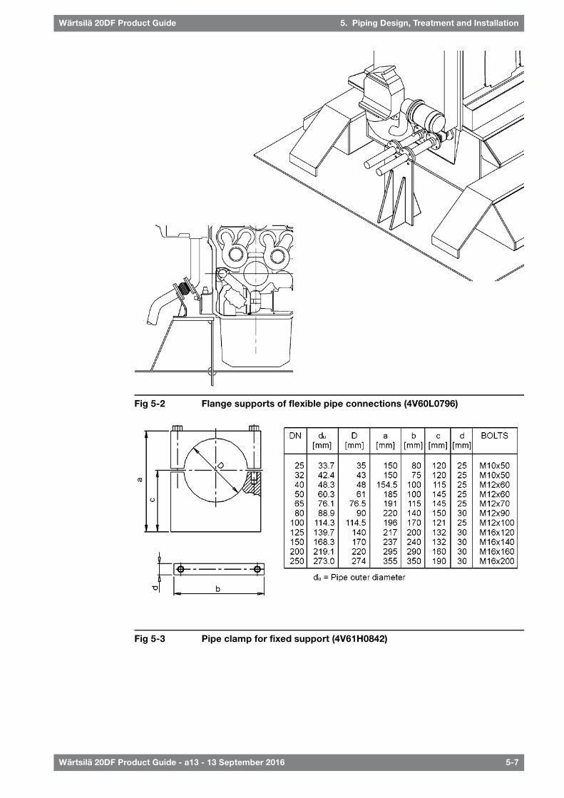
Fig 5-2 Flange supports of flexible pipe connections (4V60L0796)
Fig 5-3 Pipe clamp for fixed support (4V61H0842)
Wärtsilä 20DF Product Guide - a13 - 13 September 2016 5-7
5. Piping Design, Treatment and InstallationWärtsilä 20DF Product Guide

This page intentionally left blank

6. Fuel System
6.1 Acceptable fuel characteristics
6.1.1 Gas fuel specificationAs a dual fuel engine, the Wärtsilä 20DF engine is designed for continuous operation in gasoperating mode or diesel operating mode. For continuous operation without reduction in therated output, the gas used as main fuel in gas operating mode has to fulfill the below mentionedquality requirements.
Table 6-1 Fuel Gas Specifications
ValueUnitProperty
28MJ/m3N 2)Lower heating value (LHV), min 1)
80Methane number (MN), min 3)
70% volumeMethane (CH4), min
0.05% volumeHydrogen sulphide (H2S), max
3% volumeHydrogen (H2), max 4)
25mg/m3NAmmonia, max
50mg/m3NChlorine + Fluorines, max
50mg/m3NParticles or solids at engine inlet, max
5umParticles or solids at engine inlet, max size
0…60°CGas inlet temperature
Water and hydrocarbon condensates at engine inlet not allowed 5)
The required gas feed pressure is depending on the LHV (see section Output limitations in gas mode).1)
Values given in m³N are at 0°C and 101.3 kPa.2)
The methane number (MN) of the gas is to be defined by using AVL’s “Methane 3.20” software. The MN is a calculated valuethat gives a scale for evaluation of the resistance to knock of gaseous fuels. Above table is valid for a lowMN optimized engine.Minimum value is depending on engine configuration, which will affect the performance data.However, if the total content of hydrocarbons C5 and heavier is more than 1% volume Wärtsilä has to be contacted for furtherevaluation.
3)
Hydrogen content higher than 3% volume has to be considered project specifically.4)
Dew point of natural gas is below the minimum operating temperature and pressure.5)
6.1.2 Liquid fuel specificationThe fuel specifications are based on the ISO 8217:2012 (E) standard. Observe that a fewadditional properties not included in the standard are listed in the tables. For maximum fueltemperature before the engine, see chapter "Technical Data".
The fuel shall not contain any added substances or chemical waste, which jeopardizes thesafety of installations or adversely affects the performance of the engines or is harmful topersonnel or contributes overall to air pollution.
6.1.2.1 Pilot fuel oilThe pilot fuel shall fulfill the characteristics specified in table MDF specifications, except thatthe following additional requirement is valid for Cetane Index:
Wärtsilä 20DF Product Guide - a13 - 13 September 2016 6-1
6. Fuel SystemWärtsilä 20DF Product Guide

Table 6-2 Pilot fuel oils
Test methodref.
ISO-F-DMB
ISO-F-DMZ
ISO-F-DMA
UnitProperty
ISO 4264505050-Cetane index, min.
6.1.2.2 Marine Diesel Fuel (MDF)Distillate fuel grades are ISO-F-DMX, DMA, DMZ, DMB. These fuel grades are referred to asMDF (Marine Diesel Fuel).
The distillate grades mentioned above can be described as follows:
● DMX: A fuel which is suitable for use at ambient temperatures down to -15°C withoutheating the fuel. Especially in merchant marine applications its use is restricted to lifeboatengines and certain emergency equipment due to the reduced flash point. The low flashpoint which is not meeting the SOLAS requirement can also prevent the use in other marineapplications, unless the fuel system is built according to special requirements. Also thelow viscosity (min. 1.4 cSt) can prevent the use in engines unless the fuel can be cooleddown enough to meet the min. injection viscosity limit of the engine.
● DMA: A high quality distillate, generally designated as MGO (Marine Gas Oil).
● DMZ: A high quality distillate, generally designated as MGO (Marine Gas Oil). An alternativefuel grade for engines requiring a higher fuel viscosity than specified for DMA grade fuel.
● DMB: A general purpose fuel which may contain trace amounts of residual fuel and isintended for engines not specifically designed to burn residual fuels. It is generallydesignated as MDO (Marine Diesel Oil).
Table 6-3 MDF specifications
Test method ref.ISO-F-DMBISO-F-DMZISO-F-DMAUnitProperty
1.81.81.8cStViscosity before pilot fuel pump, min. 1)
11.011.011.0cStViscosity, before pilot fuel pump, max.1)
1.81.81.8cStViscosity, before main injection pumps, min. 1)
24.024.024.0cStViscosity, before main fuel injection pumps, max. 1)
555°CTemperature before pilot fuel pump, min. 9)
505050°CTemperature before pilot fuel pump, max 9)
232cStViscosity at 40°C, min.
ISO 31041166cStViscosity at 40°C, max.
ISO 3675 or 12185900890890kg/m³Density at 15°C, max.
ISO 4264354040Cetane index, min.
ISO 8574 or 1459621.51.5% massSulphur, max.
ISO 2719606060°CFlash point, min.
IP 570222mg/kgHydrogen sulfide. max. 2)
ASTM D6640.50.50.5mg KOH/gAcid number, max.
ISO 10307-10.1 3)——% massTotal sediment by hot filtration, max.
ISO 1220525 4)2525g/m3Oxidation stability, max.
ISO 10370—0.300.30% massCarbon residue: micro method on the 10% volumedistillation residue max.
ISO 103700.30——% massCarbon residue: micro method, max.
ISO 30160-6-6°CPour point (upper) , winter quality, max. 5)
ISO 3016600°CPour point (upper) , summer quality, max. 5)
3) 4) 7)Clear and bright 6)—Appearance
ISO 37330.3 3)——% volumeWater, max.
6-2 Wärtsilä 20DF Product Guide - a13 - 13 September 2016
Wärtsilä 20DF Product Guide6. Fuel System

Test method ref.ISO-F-DMBISO-F-DMZISO-F-DMAUnitProperty
ISO 62450.010.010.01% massAsh, max.
ISO 12156-1520 7)520520µmLubricity, corrected wear scar diameter (wsd 1.4) at60°C , max. 8)
Remarks:
Additional properties specified by Wärtsilä, which are not included in the ISO specification.1)
The implementation date for compliance with the limit shall be 1 July 2012. Until that the specified value is given for guidance.2)
If the sample is not clear and bright, the total sediment by hot filtration and water tests shall be required.3)
If the sample is not clear and bright, the test cannot be undertaken and hence the oxidation stability limit shall not apply.4)
It shall be ensured that the pour point is suitable for the equipment on board, especially if the ship operates in cold climates.5)
If the sample is dyed and not transparent, then the water limit and test method ISO 12937 shall apply.6)
If the sample is not clear and bright, the test cannot be undertaken and hence the lubricity limit shall not apply.7)
The requirement is applicable to fuels with a sulphur content below 500 mg/kg (0.050 % mass).8)
Additional properties specified by the engine manufacturer, which are not included in the ISO 8217:2012(E) standard. Themin. fuel temperature has to be always at least 10 °C above fuel’s pour point, cloud point and cold filter plugging point.
9)
NOTE
Pilot fuel quality must be according to DMX, DMA, DMZ or DMB.
Lubricating oil, foreign substances or chemical waste, hazardous to the safety ofthe installation or detrimental to the performance of engines, should not becontained in the fuel.
6.1.2.3 Heavy Fuel Oil (HFO)Residual fuel grades are referred to as HFO (Heavy Fuel Oil). The fuel specification HFO 2covers the categories ISO-F-RMA 10 to RMK 700. Fuels fulfilling the specification HFO 1permit longer overhaul intervals of specific engine components than HFO 2.
Table 6-4 HFO specifications
Test method ref.Limit HFO 2Limit HFO 1UnitProperty
16...2416...24cStViscosity, before injection pumps 1)
ISO 3104700700cStViscosity at 50°C, max.
ISO 3675 or 12185991 / 1010 2)991 / 1010 2)kg/m³Density at 15°C, max.
ISO 8217, Annex F870850CCAI, max.3)
ISO 8754 or 14596Statutory requirements% massSulphur, max. 4) 5)
ISO 27196060°CFlash point, min.
IP 57022mg/kgHydrogen sulfide, max. 6)
ASTM D6642.52.5mg KOH/gAcid number, max.
ISO 10307-20.10.1% massTotal sediment aged, max.
ISO 103702015% massCarbon residue, micro method, max.
ASTM D 3279148% massAsphaltenes, max.1)
ISO 30163030°CPour point (upper), max. 7)
ISO 3733 or ASTMD6304-C 1)
0.50.5% volumeWater, max.
ISO 3733 or ASTMD6304-C 1)
0.30.3% volumeWater before engine, max.1)
ISO 6245 or LP1001 1)0.150.05% massAsh, max.
ISO 14597 or IP 501or IP 470
450100mg/kgVanadium, max. 5)
IP 501 or IP 47010050mg/kgSodium, max. 5)
Wärtsilä 20DF Product Guide - a13 - 13 September 2016 6-3
6. Fuel SystemWärtsilä 20DF Product Guide

Test method ref.Limit HFO 2Limit HFO 1UnitProperty
IP 501 or IP 4703030mg/kgSodium before engine, max.1) 5)
ISO 10478 or IP 501or IP 470
6030mg/kgAluminium + Silicon, max.
ISO 10478 or IP 501or IP 470
1515mg/kgAluminium + Silicon before engine, max.1)
IP 501 or IP 4703030mg/kgUsed lubricating oil, calcium, max. 8)
IP 501 or IP 4701515mg/kgUsed lubricating oil, zinc, max. 8)
IP 501 or IP 5001515mg/kgUsed lubricating oil, phosphorus, max. 8)
Remarks:
Additional properties specified by Wärtsilä, which are not included in the ISO specification.1)
Max. 1010 kg/m³ at 15°C provided that the fuel treatment system can remove water and solids (sediment, sodium, aluminium,silicon) before the engine to specified levels.
2)
Straight run residues show CCAI values in the 770 to 840 range and have very good ignition quality. Cracked residues deliveredas bunkers may range from 840 to - in exceptional cases - above 900. Most bunkers remain in the max. 850 to 870 range atthe moment. CCAI value cannot always be considered as an accurate tool to determine the ignition properties of the fuel,especially concerning fuels originating from modern and more complex refinery process.
3)
The max. sulphur content must be defined in accordance with relevant statutory limitations.4)
Sodium contributes to hot corrosion on the exhaust valves when combined with high sulphur and vanadium contents. Sodiumalso strongly contributes to fouling of the exhaust gas turbine blading at high loads. The aggressiveness of the fuel dependson its proportions of sodium and vanadium and also on the total amount of ash. Hot corrosion and deposit formation are,however, also influenced by other ash constituents. It is therefore difficult to set strict limits based only on the sodium andvanadium content of the fuel. Also a fuel with lower sodium and vanadium contents than specified above, can cause hotcorrosion on engine components.
5)
The implementation date for compliance with the limit shall be 1 July 2012. Until that, the specified value is given for guidance.6)
It shall be ensured that the pour point is suitable for the equipment on board, especially if the ship operates in cold climates.7)
The fuel shall be free from used lubricating oil (ULO). A fuel shall be considered to contain ULO when either one of the followingconditions is met:
● Calcium > 30 mg/kg and zinc > 15 mg/kg
● Calcium > 30 mg/kg and phosphorus > 15 mg/kg
8)
6.2 Operating principlesWärtsilä 20DF engines are usually installed for dual fuel operation meaning the engine can berun either in gas or diesel operating mode. The operating mode can be changed while theengine is running, within certain limits, without interruption of power generation. If the gassupply would fail, the engine will automatically transfer to diesel mode operation (MDF).
6.2.1 Gas mode operationIn gas operating mode the main fuel is natural gas which is injected into the engine at a lowpressure. The gas is ignited by injecting a small amount of pilot diesel fuel (MDF). Gas andpilot fuel injection are solenoid operated and electronically controlled common rail systems.
6.2.2 Diesel mode operationIn diesel operating mode the engine operates only on liquid fuel oil. MDF or HFO is used asfuel with a conventional diesel fuel injection system. The MDF pilot injection is always active.
6.2.3 Backup mode operationThe engine control and safety system or the blackout detection system can in some situationstransfer the engine to backup mode operation. In this mode the MDF pilot injection system isnot active and operation longer than 30 minutes (with HFO) or 5 hours (with MDF) may causeclogging of the pilot fuel injection nozzles.
Engine load must also be kept below 70%.
6-4 Wärtsilä 20DF Product Guide - a13 - 13 September 2016
Wärtsilä 20DF Product Guide6. Fuel System

6.3 Fuel gas system
6.3.1 Internal fuel gas system
Fig 6-1 Internal fuel gas system (DAAF013944E)
System components
Cylinder03Safety filter01
Venting valve04Gas admission valve02
Sensors and indicators
Knock sensor, cyl A0#SE60#4A..
Main gas pressurePT901
SizePipe connections
DN65/100Gas inlet108
DN25Gas system ventilation708
M26*1.5Air inlet to double wall gas system726
When operating the engine in gas mode, the gas is injected through gas admission valves intothe inlet channel of each cylinder. The gas is mixed with the combustion air immediatelyupstream of the inlet valve in the cylinder head. Since the gas valve is timed independently ofthe inlet valve, scavenging of the cylinder is possible without risk that unburned gas is escapingdirectly from the inlet to the exhaust.
The annular space in double wall piping is ventilated artificially by underpressure created byventilation fans. The air inlet to the annular space is located at the engine. The ventilation airis to be taken from a location outside the engine room, through dedicated piping. In addition,the ventilation requirements from the project specific classification society is to be consideredin the design.
Wärtsilä 20DF Product Guide - a13 - 13 September 2016 6-5
6. Fuel SystemWärtsilä 20DF Product Guide

6.3.2 External fuel gas system
6.3.2.1 Fuel gas system, with instrument cabinet
Fig 6-2 Example of fuel gas system with instrument cabinet (DAAF022750D)
Pipe connectionsSystem components
Gas inlet108Gas detector01
Gas system ventilation708Gas double wall system ventilation fan02
Air inlet to double wall gas system726Gas valve unit10N05
LNGPAC10N08
6-6 Wärtsilä 20DF Product Guide - a13 - 13 September 2016
Wärtsilä 20DF Product Guide6. Fuel System

6.3.2.2 Fuel gas system, with solenoid valve cabinet
Fig 6-3 Example of fuel gas system with solenoid valve cabinet (DAAF077105)
Pipe connectionsSystem components
Gas inlet108Gas detector01
Gas system ventilation708Gas double wall system ventilation fan02
Air inlet to double wall gas system726Gas valve unit10N05
LNGPAC10N08
Wärtsilä 20DF Product Guide - a13 - 13 September 2016 6-7
6. Fuel SystemWärtsilä 20DF Product Guide

The fuel gas can typically be contained as CNG, LNG at atmospheric pressure, or pressurizedLNG. The design of the external fuel gas feed system may vary, but every system shouldprovide natural gas with the correct temperature and pressure to each engine.
6.3.2.3 Double wall gas piping and the ventilation of the pipingThe annular space in double wall piping is ventilated artificially by underpressure created byventilation fans. The first ventilation air inlet to the annular space is located at the engine. Theventilation air is recommended to be taken from a location outside the engine room, throughdedicated piping. The second ventilation air inlet is located at the outside of the tank connectionspace at the end of the double wall piping. To balance the air intake of the two air intakes aflow restrictor is required at the air inlet close to the tank connection space. The ventilationair is taken from both inlets and lead through the annular space of the double wall pipe to theGVU room or to the enclosure of the gas valve unit. From the enclosure of the gas valve unita dedicated ventilation pipe is connected to the ventilation fans and from the fans the pipecontinues to the safe area. The 1,5 meter hazardous area will be formed at the ventilation airinlet and outlet and is to be taken in consideration when the ventilation piping is designed.According to classification societies minimum ventilation capacity has to be at least 30 airchanges per hour. With enclosed GVU this 30 air changes per hour normally correspond to-20 mbar inside the GVU enclosure according to experience from existing installations. However,in some cases required pressure in the ventilation might be slightly higher than -20 mbar andcan be accepted based on case analysis and measurements.
Fig 6-4 Example arrangement drawing of ventilation in double wall piping systemwith enclosed GVUs (DBAC588146)
6-8 Wärtsilä 20DF Product Guide - a13 - 13 September 2016
Wärtsilä 20DF Product Guide6. Fuel System

6.3.2.4 Gas valve unit (10N05)Before the gas is supplied to the engine it passes through a Gas Valve Unit (GVU). The GVUinclude a gas pressure control valve and a series of block and bleed valves to ensure reliableand safe operation on gas.
The unit includes a manual shut-off valve, inerting connection, filter, fuel gas pressure controlvalve, shut-off valves, ventilating valves, pressure transmitters/gauges, a gas temperaturetransmitter and control cabinets.
The filter is a full flow unit preventing impurities from entering the engine fuel gas system. Thefineness of the filter is 5 μm absolute mesh size. The pressure drop over the filter is monitoredand an alarm is activated when pressure drop is above permitted value due to dirty filter.
The fuel gas pressure control valve adjusts the gas feed pressure to the engine according toengine load. The pressure control valve is controlled by the engine control system. The systemis designed to get the correct fuel gas pressure to the engine common rail pipe at all times.
Readings from sensors on the GVU as well as opening and closing of valves on the gas valveunit are electronically or electro-pneumatically controlled by the GVU control system. Allreadings from sensors and valve statuses can be read from Local Display Unit (LDU). The LDUis mounted on control cabinet of the GVU.
The two shut-off valves together with gas ventilating valve (between the shut-off valves) forma double-block-and-bleed function. The block valves in the double-block-and-bleed functioneffectively close off gas supply to the engine on request. The solenoid operated venting valvein the double-block-and-bleed function will relief the pressure trapped between the blockvalves after closing of the block valves. The block valves V03 and V05 and inert gas valve V07are operated as fail-to-close, i.e. they will close on current failure. Venting valves V02 and V04are fail-to-open, they will open on current failure. There is a connection for inerting the fuelgas pipe with nitrogen, see figure "Gas valve unit P&I diagram". The inerting of the fuel gaspipe before double block and bleed valves in the GVU is done from gas storage system. Gasis blown downstream the fuel gas pipe and out via vent valve V02 on the GVU when inertingfrom gas storage system.
During a stop sequence of DF-engine gas operation (i.e. upon gas trip, pilot trip, stop,emergency stop or shutdown in gas operating mode, or transfer to diesel operating mode)the GVU performs a gas shut-off and ventilation sequence. Both block valves (V03 and V05)on the gas valve unit are closed and ventilation valve V04 between block valves is opened.Additionally on emergency stop ventilation valve V02 will open and on certain alarm situationsthe V07 will inert the gas pipe between GVU and the engine.
The gas valve unit will perform a leak test procedure before engine starts operating on gas.This is a safety precaution to ensure the tightness of valves and the proper function ofcomponents.
One GVU is required for each engine. The GVU has to be located close to the engine to ensureengine response to transient conditions. The maximum length of fuel gas pipe between theGVU and the engine gas inlet is 10 m.
Inert gas and compressed air are to be dry and clean. Inert gas pressure max 1.5 MPa (15bar). The requirements for compressed air quality are presented in chapter "Compressed airsystem".
Wärtsilä 20DF Product Guide - a13 - 13 September 2016 6-9
6. Fuel SystemWärtsilä 20DF Product Guide

Fig 6-5 Gas valve unit P&I diagram (DAAF051037C)
Unit components:
Shut off valveV08First block valveV03Gas filterB01
Shut off valveV09Vent valveV04Control air filterB02
Pressure regulatorV10Second block valveV05Inert gas filterB03
Solenoid valveCV-V0#Gas control valveV06Manual shut off valveV01
Mass flow meterQ01Inerting valveV07Vent valveV02
Sensors and indicators
Pressure transmitter, inert gasP05Pressure transmitter, gas inletP01
Pressure transmitter, control airP06Pressure manometer, gas inletP02
Pressure difference transmitterP07Pressure transmitterP03
Temperature sensor, gas inletT01Pressure transmitter, gas outletP04
Pipe connections
Gas ventingD1Gas inlet [5-10 bar(g)]A1
Air ventingD2Gas to engineB1
Instrument air [6-8 bar(g)]X1Inert gas [max 15 bar(g)]B2
Pipe size
DN100 GVUDN80 GVUDN50 GVUPosDN100 GVUDN80 GVUDN50 GVUPos
DN150DN125DN100PN6DN100DN80DN50P1
DN100DN80DN50PN7DN100DN80DN40P2
OD42OD28OD18PN8DN80DN50DN40P3
OD28OD28OD22PN9DN80DN50DN40P4
10mm10mm10mmPN10DN100DN80DN65P5
6-10 Wärtsilä 20DF Product Guide - a13 - 13 September 2016
Wärtsilä 20DF Product Guide6. Fuel System

Fig 6-6 Main dimensions of the GVU (DAAF018131A)
6.3.2.5 Master fuel gas valveFor LNG carriers, IMO IGC code requires a master gas fuel valve to be installed in the fuel gasfeed system. At least one master gas fuel valve is required, but it is recommended to applyone valve for each engine compartment using fuel gas to enable independent operation.
It is always recommended to have one main shut-off valve directly outside the engine roomand valve room in any kind of installation.
6.3.2.6 Fuel gas ventingIn certain situations during normal operation of a DF-engine, as well as due to possible faults,there is a need to safely ventilate the fuel gas piping. During a stop sequence of a DF-enginegas operation the GVU and DF-engine gas venting valves performs a ventilation sequence torelieve pressure from gas piping. Additionally in emergency stop V02 will relief pressure fromgas piping upstream from the GVU.
This small amount of gas can be ventilated outside into the atmosphere, to a place wherethere are no sources of ignition.
Alternatively to ventilating outside into the atmosphere, other means of disposal (e.g. a suitablefurnace) can also be considered. However, this kind of arrangement has to be accepted byclassification society on a case by case basis.
NOTE
All breathing and ventilation pipes that may contain fuel gas must always be builtsloping upwards, so that there is no possibility of fuel gas accumulating inside thepiping.
In case the DF-engine is stopped in gas operating mode, the ventilation valves will openautomatically and quickly reduce the gas pipe pressure to atmospheric pressure.
The pressure drop in the venting lines are to be kept at a minimum.
To prevent gas ventilation to another engine during maintenance vent lines from gas supplyor GVU of different engines cannot be interconnected. However, vent lines from the sameengine can be interconnected to a common header, which shall be lead to the atmosphere.Connecting the engine or GVU venting lines to the LNGPac venting mast is not allowed, dueto risk for backflow of gas into the engine room when LNGPac gas is vented!
Wärtsilä 20DF Product Guide - a13 - 13 September 2016 6-11
6. Fuel SystemWärtsilä 20DF Product Guide

6.3.2.7 Purging by inert gasBefore beginning maintenance work, the fuel gas piping system has to be de-pressurized andinerted with an inert gas. If maintenance work is done after the GVU and the enclosure of theGVU hasn’t been opened, it is enough to inert the fuel gas pipe between the GVU and engineby triggering the starting sequence from the GVU control cabinet.
If maintenance work is done on the GVU and the enclosure of the GVU need to be opened,the fuel gas pipes before and after the GVU need to be inerted. Downstream from the GVUincluding the engine built gas piping, inerting is performed by triggering the inerting sequencefrom the GVU control cabinet. Regarding the engine crankcase inerting, a separate inert gasconnection exist located on the engine. Upstream from the GVUdouble-block-and-bleed-valves, the inerting is performed from the gas storage system byfeeding inert gas downstream the fuel gas pipe and out from the GVU gas ventilation pipe.
In addition to maintenance, during certain alarm and emergency situations (e.g. annular spaceventilation failure and/or gas leak detection), the fuel gas piping is to be flushed with inert gas.
The following guidelines apply for flushing the engine crankcase with inert gas:
1 Max filling flow: 50l/min/cylinder
2 A sniffer is recommended to be installed in the crankcase breather pipe in order toindicate when the crankcase have been flushed from toxic gases.
3 Crankcase size: 0.22m3/crank
6.3.2.8 Gas feed pressureThe required fuel gas feed pressure depends on the expected minimum lower heating value(LHV) of the fuel gas, as well as the pressure losses in the feed system to the engine. The LHVof the fuel gas has to be above 28 MJ/m3 at 0°C and 101.3 kPa. For pressure requirements,see section "Technical Data" and chapter "1.3.2 Output limitations due to gas feed pressureand lower heating value"
For pressure requirements, see chapters Technical Data and Output limitations due to methanenumber.
● The pressure losses in the gas feed system to engine has to be added to get the requiredgas pressure.
● A pressure drop of 120 kPa over the GVU is a typical value that can be used as guidance.
● The required gas pressure to the engine depends on the engine load. This is regulated bythe GVU.
6-12 Wärtsilä 20DF Product Guide - a13 - 13 September 2016
Wärtsilä 20DF Product Guide6. Fuel System

6.4 Fuel oil system
6.4.1 Internal fuel oil system
6.4.1.1 Internal fuel oil system MDF, with engine driven fuel feed pump
Fig 6-7 Internal fuel oil system MDF, with engine driven fuel feed pump(DAAF013947D)
System components
Pilot fuel pump08Pressure relief valve04Injection pump01
Particle filter09Engine driven fuel feed pump05Injection valve02
Pulse damper10Fuel filter06Level alarm for leak fuel from inj.pipes
03
Pilot fuel safety valve11Pilot injector07
Sensors and indicators
Pilot fuel oil temperature, inletTE112Fuel oil pressure, engine inletPT101
Fuel oil filter pressure differencePDS113Fuel oil temperature, engine inletTE101
Pilot fuel oil pressure controlCV124Fuel oil temperature, engine inletTI101
Pilot fuel oil pressure, pump outletPT125Fuel oil leakage, clean primary, A-bankLS103A
Pilot fuel filter pressure, pump outletPDS129FO stand-by pump start (if stand-by pump)PS110
Pilot fuel oil pressure, inletPT112
StandardSizePipe connections
DIN 2353OD28Fuel inlet101
DIN 2353OD28Fuel outlet102
DIN 2353OD18Leak fuel drain, clean fuel103
DIN 2353OD22Fuel stand-by connection (if stand-by pump)105
DIN 2353OD10Pilot fuel inlet112
DIN 2353OD15Pilot fuel outlet117
DIN 2353OD22Leak fuel drain, dirty fuel free end1041
DIN 2353OD18Leak fuel drain, dirty fuel flywheel end1043
Wärtsilä 20DF Product Guide - a13 - 13 September 2016 6-13
6. Fuel SystemWärtsilä 20DF Product Guide

6.4.1.2 Internal fuel oil system MDF, without engine driven fuel feedpump
Fig 6-8 Internal fuel oil system MDF, without engine driven fuel feed pump(DAAF013946D)
System components
Pilot injector07Injection pump01
Pilot fuel pump08Injection valve02
Particle filter09Level alarm for leak fuel from injection pipes03
Pulse damper10Adjustable orifice04
Pilot fuel safety valve11Engine driven fuel feed pump05
Fuel filter06
Sensors and indicators
Pilot fuel oil pressure, inletPT112Fuel oil pressure, engine inletPT101
Pilot fuel oil temperature, inletTE112Fuel oil temperature, engine inletTE101
Pilot fuel oil pressure controlCV124Fuel oil temperature, engine inletTI101
Pilot fuel oil pressure, pump outletPT125Fuel oil leakage, clean primary, A-bankLS103A
Pilot fuel filter pressure, pump outletPDS129Fuel oil stand-by pump startPS110
StandardSizePipe connections
DIN 2353OD18Fuel inlet101
DIN 2353OD18Fuel outlet102
DIN 2353OD18Leak fuel drain, clean fuel103
DIN 2353OD10Pilot fuel inlet112
DIN 2353OD15Pilot fuel outlet117
DIN 2353OD22Leak fuel drain, dirty fuel free end1041
DIN 2353OD18Leak fuel drain, dirty fuel flywheel end1043
6-14 Wärtsilä 20DF Product Guide - a13 - 13 September 2016
Wärtsilä 20DF Product Guide6. Fuel System

6.4.1.3 Internal fuel oil system HFO
Fig 6-9 Internal fuel oil system HFO (DAAF014207E)
System components
Pilot fuel pump06Injection pump01
Pilot injector07Injection valve02
Pilot fuel filter08Level alarm for leak fuel from injection pipes03
Pilot fuel safety valve09Adjustable orifice04
Pulse damper05
Sensors and indicators
Pilot fuel oil pressure, inletPT112Fuel oil pressure, engine inletPT101
Pilot fuel oil temperature, inletTE112Fuel oil temperature, engine inletTE101
Pilot fuel oil pressure controlCV124Fuel oil temperature, engine inletTI101
Pilot fuel oil pressure, pump outletPT125Fuel oil leakage, clean primary, A-bankLS103A
Pilot fuel filter pressure, pump outletPDS129Fuel oil stand-by pump startPS110
SizePipe connections
OD18Fuel inlet101
OD18Fuel outlet102
OD18Leak fuel drain, clean fuel103
OD10Pilot fuel inlet112
OD15Pilot fuel outlet117
OD22Leak fuel drain, dirty fuel free end1041
OD18Leak fuel drain, dirty fuel flywheel end1043
Wärtsilä 20DF Product Guide - a13 - 13 September 2016 6-15
6. Fuel SystemWärtsilä 20DF Product Guide

There are separate pipe connections for the main fuel oil and pilot fuel oil. Main fuel oil canbe Marine Diesel Fuel (MDF) or Heavy Fuel Oil (HFO). Pilot fuel oil is always MDF and the pilotfuel system is in operation in both gas- and diesel mode operation.
A pressure control valve in the main fuel oil return line on the engine maintains desired pressurebefore the injection pumps.
6.4.1.4 Leak fuel systemClean leak fuel from the injection valves and the injection pumps is collected on the engineand drained by gravity through a clean leak fuel connection. The clean leak fuel can be re-usedwithout separation. The quantity of clean leak fuel is given in chapter Technical data.
Other possible leak fuel and spilled water and oil is separately drained from the hot-box throughdirty fuel oil connections and it shall be led to a sludge tank.
6.4.2 External fuel oil systemThe design of the external fuel system may vary from ship to ship, but every system shouldprovide well cleaned fuel of correct viscosity and pressure to each engine. Temperature controlis required to maintain stable and correct viscosity of the fuel before the injection pumps (seeTechnical data). Sufficient circulation through every engine connected to the same circuit mustbe ensured in all operating conditions.
The fuel treatment system should comprise at least one settling tank and two separators.Correct dimensioning of HFO separators is of greatest importance, and therefore therecommendations of the separator manufacturer must be closely followed. Poorly centrifugedfuel is harmful to the engine and a high content of water may also damage the fuel feed system.
Injection pumps generate pressure pulses into the fuel feed and return piping. The fuel pipesbetween the feed unit and the engine must be properly clamped to rigid structures. Thedistance between the fixing points should be at close distance next to the engine. See chapterPiping design, treatment and installation.
A connection for compressed air should be provided before the engine, together with a drainfrom the fuel return line to the clean leakage fuel or overflow tank. With this arrangement it ispossible to blow out fuel from the engine prior to maintenance work, to avoid spilling.
NOTE
In multiple engine installations, where several engines are connected to the samefuel feed circuit, it must be possible to close the fuel supply and return linesconnected to the engine individually. This is a SOLAS requirement. It is furtherstipulated that the means of isolation shall not affect the operation of the otherengines, and it shall be possible to close the fuel lines from a position that is notrendered inaccessible due to fire on any of the engines.
6.4.2.1 Fuel heating requirements HFOHeating is required for:
● Bunker tanks, settling tanks, day tanks
● Pipes (trace heating)
● Separators
● Fuel feeder/booster units
To enable pumping the temperature of bunker tanks must always be maintained 5...10°Cabove the pour point, typically at 40...50°C. The heating coils can be designed for a temperatureof 60°C.
The tank heating capacity is determined by the heat loss from the bunker tank and the desiredtemperature increase rate.
6-16 Wärtsilä 20DF Product Guide - a13 - 13 September 2016
Wärtsilä 20DF Product Guide6. Fuel System

Fig 6-10 Fuel oil viscosity-temperature diagram for determining the pre-heatingtemperatures of fuel oils (4V92G0071b)
Example 1: A fuel oil with a viscosity of 380 cSt (A) at 50°C (B) or 80 cSt at 80°C (C) must bepre-heated to 115 - 130°C (D-E) before the fuel injection pumps, to 98°C (F) at the separatorand to minimum 40°C (G) in the bunker tanks. The fuel oil may not be pumpable below 36°C(H).
To obtain temperatures for intermediate viscosities, draw a line from the knownviscosity/temperature point in parallel to the nearest viscosity/temperature line in the diagram.
Example 2: Known viscosity 60 cSt at 50°C (K). The following can be read along the dottedline: viscosity at 80°C = 20 cSt, temperature at fuel injection pumps 74 - 87°C, separatingtemperature 86°C, minimum bunker tank temperature 28°C.
6.4.2.2 Fuel tanksThe fuel oil is first transferred from the bunker tanks to settling tanks for initial separation ofsludge and water. After centrifuging the fuel oil is transferred to day tanks, from which fuel issupplied to the engines.
6.4.2.2.1 Settling tank, HFO (1T02) and MDF (1T10)
Separate settling tanks for HFO and MDF are recommended.
Wärtsilä 20DF Product Guide - a13 - 13 September 2016 6-17
6. Fuel SystemWärtsilä 20DF Product Guide

To ensure sufficient time for settling (water and sediment separation), the capacity of eachtank should be sufficient for min. 24 hours operation at maximum fuel consumption.
The tanks should be provided with internal baffles to achieve efficient settling and have asloped bottom for proper draining.
The temperature in HFO settling tanks should be maintained between 50°C and 70°C, whichrequires heating coils and insulation of the tank. Usuallly MDF settling tanks do not needheating or insulation, but the tank temperature should be in the range 20...40°C.
6.4.2.2.2 Day tank, HFO (1T03) and MDF (1T06)
Two day tanks for HFO are to be provided, each with a capacity sufficient for at least 8 hoursoperation at maximum fuel consumption.
A separate tank is to be provided for MDF. The capacity of the MDF tank should ensure fuelsupply for 8 hours.
Settling tanks may not be used instead of day tanks.
The day tank must be designed so that accumulation of sludge near the suction pipe isprevented and the bottom of the tank should be sloped to ensure efficient draining.
HFO day tanks shall be provided with heating coils and insulation. It is recommended that theviscosity is kept below 140 cSt in the day tanks. Due to risk of wax formation, fuels with aviscosity lower than 50 cSt at 50°C must be kept at a temperature higher than the viscositywould require. Continuous separation is nowadays common practice, which means that theHFO day tank temperature normally remains above 90°C.
The temperature in the MDF day tank should be in the range 20...40°C.
The level of the tank must ensure a positive static pressure on the suction side of the fuel feedpumps. If black-out starting with MDF from a gravity tank is foreseen, then the tank must belocated at least 15 m above the engine crankshaft.
6.4.2.2.3 Leak fuel tank, clean fuel (1T04)
Clean leak fuel is drained by gravity from the engine. The fuel should be collected in a separateclean leak fuel tank, from where it can be pumped to the day tank and reused withoutseparation. The pipes from the engine to the clean leak fuel tank should be arranged continuoslysloping. The tank and the pipes must be heated and insulated, unless the installation is designedfor operation on MDF only.
In HFO installations the change over valve for leak fuel (1V13) is needed to avoid mixing ofthe MDF and HFO clean leak fuel. When operating the engines in gas mode and MDF iscirculating in the system, the clean MDF leak fuel shall be directed to the MDF clean leak fueltank. Thereby the MDF can be pumped back to the MDF day tank (1T06).
When switching over from HFO to MDF the valve 1V13 shall direct the fuel to the HFO leakfuel tank long time enough to ensure that no HFO is entering the MDF clean leak fuel tank.
Refer to section "Fuel feed system - HFO installations" for an example of the external HFOfuel oil system.
The leak fuel piping should be fully closed to prevent dirt from entering the system.
6.4.2.2.4 Leak fuel tank, dirty fuel (1T07)
In normal operation no fuel should leak out from the components of the fuel system. Inconnection with maintenance, or due to unforeseen leaks, fuel or water may spill in the hotbox of the engine. The spilled liquids are collected and drained by gravity from the enginethrough the dirty fuel connection.
Dirty leak fuel shall be led to a sludge tank. The tank and the pipes must be heated andinsulated, unless the installation is designed for operation exclusively on MDF.
6-18 Wärtsilä 20DF Product Guide - a13 - 13 September 2016
Wärtsilä 20DF Product Guide6. Fuel System

6.4.2.2.5 Pilot fuel tank, LFO (1T15)
The pilot fuel is used to ignite the air-gas mixture in the cylinder when operating the engine isin gas mode. The pilot fuel should be of type MDF and stored in a pilot fuel tank. The pilot fueltank temperature should be max 45°C and the capacity sufficient for at least 8 hours operation.
The pilot fuel tank should be situated below the pilot fuel pump.
Alternatively, as described in the recommended external system drawings, a common fuel oilsystem (for main and pilot fuel oil) can be applied. In such installation, no separate pilot fueloil tank is needed.
6.4.2.3 Fuel treatment
6.4.2.3.1 Separation
Heavy fuel (residual, and mixtures of residuals and distillates) must be cleaned in an efficientcentrifugal separator before it is transferred to the day tank.
Classification rules require the separator arrangement to be redundant so that required capacityis maintained with any one unit out of operation.
All recommendations from the separator manufacturer must be closely followed.
Centrifugal disc stack separators are recommended also for installations operating on MDFonly, to remove water and possible contaminants. The capacity of MDF separators should besufficient to ensure the fuel supply at maximum fuel consumption. Would a centrifugal separatorbe considered too expensive for a MDF installation, then it can be accepted to use coalescingtype filters instead. A coalescing filter is usually installed on the suction side of the circulationpump in the fuel feed system. The filter must have a low pressure drop to avoid pump cavitation.
Separator mode of operation
The best separation efficiency is achieved when also the stand-by separator is in operationall the time, and the throughput is reduced according to actual consumption.
Separators with monitoring of cleaned fuel (without gravity disc) operating on a continuousbasis can handle fuels with densities exceeding 991 kg/m3 at 15°C. In this case the main andstand-by separators should be run in parallel.
When separators with gravity disc are used, then each stand-by separator should be operatedin series with another separator, so that the first separator acts as a purifier and the secondas clarifier. This arrangement can be used for fuels with a density of max. 991 kg/m3 at 15°C.The separators must be of the same size.
Separation efficiency
The term Certified Flow Rate (CFR) has been introduced to express the performance ofseparators according to a common standard. CFR is defined as the flow rate in l/h, 30 minutesafter sludge discharge, at which the separation efficiency of the separator is 85%, when usingdefined test oils and test particles. CFR is defined for equivalent fuel oil viscosities of 380 cStand 700 cSt at 50°C. More information can be found in the CEN (European Committee forStandardisation) document CWA 15375:2005 (E).
The separation efficiency is measure of the separator's capability to remove specified testparticles. The separation efficiency is defined as follows:
where:
separation efficiency [%]n =
number of test particles in cleaned test oilCout =
Wärtsilä 20DF Product Guide - a13 - 13 September 2016 6-19
6. Fuel SystemWärtsilä 20DF Product Guide

number of test particles in test oil before separatorCin =
6.4.2.3.2 Separator unit (1N02/1N05)
Separators are usually supplied as pre-assembled units designed by the separatormanufacturer.
Typically separator modules are equipped with:
● Suction strainer (1F02)
● Feed pump (1P02)
● Pre-heater (1E01)
● Sludge tank (1T05)
● Separator (1S01/1S02)
● Sludge pump
● Control cabinets including motor starters and monitoring
Fig 6-11 Fuel transfer and separating system (V76F6626F)
6-20 Wärtsilä 20DF Product Guide - a13 - 13 September 2016
Wärtsilä 20DF Product Guide6. Fuel System

6.4.2.3.3 Separator feed pumps (1P02)
Feed pumps should be dimensioned for the actual fuel quality and recommended throughputof the separator. The pump should be protected by a suction strainer (mesh size about 0.5mm)
An approved system for control of the fuel feed rate to the separator is required.
MDFHFODesign data:
0.5 MPa (5 bar)0.5 MPa (5 bar)Design pressure
50°C100°CDesign temperature
100 cSt1000 cStViscosity for dimensioning electric motor
6.4.2.3.4 Separator pre-heater (1E01)
The pre-heater is dimensioned according to the feed pump capacity and a given settling tanktemperature.
The surface temperature in the heater must not be too high in order to avoid cracking of thefuel. The temperature control must be able to maintain the fuel temperature within ± 2°C.
Recommended fuel temperature after the heater depends on the viscosity, but it is typically98°C for HFO and 20...40°C for MDF. The optimum operating temperature is defined by thesperarator manufacturer.
The required minimum capacity of the heater is:
where:
heater capacity [kW]P =
capacity of the separator feed pump [l/h]Q =
temperature rise in heater [°C]ΔT =
For heavy fuels ΔT = 48°C can be used, i.e. a settling tank temperature of 50°C. Fuels havinga viscosity higher than 5 cSt at 50°C require pre-heating before the separator.
The heaters to be provided with safety valves and drain pipes to a leakage tank (so that thepossible leakage can be detected).
6.4.2.3.5 Separator (1S01/1S02)
Based on a separation time of 23 or 23.5 h/day, the service throughput Q [l/h] of the separatorcan be estimated with the formula:
where:
max. continuous rating of the diesel engine(s) [kW]P =
specific fuel consumption + 15% safety margin [g/kWh]b =
density of the fuel [kg/m3]ρ =
daily separating time for self cleaning separator [h] (usually = 23 h or 23.5 h)t =
Wärtsilä 20DF Product Guide - a13 - 13 September 2016 6-21
6. Fuel SystemWärtsilä 20DF Product Guide

The flow rates recommended for the separator and the grade of fuel must not be exceeded.The lower the flow rate the better the separation efficiency.
Sample valves must be placed before and after the separator.
6.4.2.3.6 MDF separator in HFO installations (1S02)
A separator for MDF is recommended also for installations operating primarily on HFO. TheMDF separator can be a smaller size dedicated MDF separator, or a stand-by HFO separatorused for MDF.
6.4.2.3.7 Sludge tank (1T05)
The sludge tank should be located directly beneath the separators, or as close as possiblebelow the separators, unless it is integrated in the separator unit. The sludge pipe must becontinuously falling.
6-22 Wärtsilä 20DF Product Guide - a13 - 13 September 2016
Wärtsilä 20DF Product Guide6. Fuel System

6.4.2.4 Fuel feed system - MDF installations
6.4.2.4.1 Fuel oil system (MDF), single engine installation
Fig 6-12 Example of fuel oil system (MDF), single engine installation (DAAF013948E)
Pipe connectionsSystem components
Fuel inlet101Cooler (MDF)1E04
Fuel outlet102Fine filter (MDF)1F05
Leak fuel drain, clean fuel103Suction strainer (MDF)1F07
Leak fuel drain, dirty fuel1041Pilot fuel fine filter (MDF)1F10
Leak fuel drain, dirty fuel1043Flow meter (MDF)1I03
Pilot fuel inlet112Circulation pump (MDF)1P03
Pilot fuel outlet117Day tank (MDF)1T06
Quick closing valve (fuel oil tank)1V10
Wärtsilä 20DF Product Guide - a13 - 13 September 2016 6-23
6. Fuel SystemWärtsilä 20DF Product Guide

6.4.2.4.2 Fuel oil system (MDF), with black start unit
Fig 6-13 Example of fuel oil system (MDF), with black start unit (DAAF056783B)
Pipe connectionsSystem components
Fuel inlet101Cooler (MDF)1E04
Fuel outlet102Fine filter (MDF)1F05
Leak fuel drain, clean fuel103Suction strainer (MDF)1F07
Leak fuel drain, dirty fuel1041Pilot fuel fine filter (MDF)1F10
Leak fuel drain, dirty fuel1043Circulation pump (MDF)1P03
Pilot fuel inlet112Black start FO pump unit1N13
Pilot fuel outlet117Day tank (MDF)1T06
Pressure control valve (MDF)1V02
Quick closing valve (fuel oil tank)1V10
Pilot fuel pressure control valve (MDF)1V14
6-24 Wärtsilä 20DF Product Guide - a13 - 13 September 2016
Wärtsilä 20DF Product Guide6. Fuel System

6.4.2.4.3 Fuel oil system (MDF), multiple engine installation
Fig 6-14 Example of fuel oil system (MDF), multiple engine installation(DAAF013949D)
Pipe connectionsSystem components
Fuel inlet101Cooler (MDF)1E04
Fuel outlet102Suction strainer (MDF)1F07
Leak fuel drain, clean fuel103Pilot fuel fine filter (MDF)1F10
Leak fuel drain, dirty fuel1041Stand-by pump (MDF)1P08
Leak fuel drain, dirty fuel1043Day tank (MDF)1T06
Fuel stand-by connection105Quick closing valve (fuel oil tank)1V10
Pilot fuel inlet112
Pilot fuel outlet117
Wärtsilä 20DF Product Guide - a13 - 13 September 2016 6-25
6. Fuel SystemWärtsilä 20DF Product Guide

If the engines are to be operated on MDF only, heating of the fuel is normally not necessary.In such case it is sufficient to install the equipment listed below. Some of the equipment listedbelow is also to be installed in the MDF part of a HFO fuel oil system.
6.4.2.4.4 Circulation pump, MDF (1P03)
The circulation pump maintains the pressure at the injection pumps and circulates the fuel inthe system. It is recommended to use a screw pump as circulation pump. A suction strainerwith a fineness of 0.5 mm should be installed before each pump. There must be a positivestatic pressure of about 30 kPa on the suction side of the pump.
Design data:
5 x the total consumption of the connected enginesCapacity
1.6 MPa (16 bar)Design pressure
1.0 MPa (10 bar)Max. total pressure (safety valve)
see chapter "Technical Data"Nominal pressure
50°CDesign temperature
90 cStViscosity for dimensioning of electricmotor
6.4.2.4.5 Flow meter, MDF (1I03)
If the return fuel from the engine is conducted to a return fuel tank instead of the day tank,one consumption meter is sufficient for monitoring of the fuel consumption, provided that themeter is installed in the feed line from the day tank (before the return fuel tank). A fuel oil cooleris usually required with a return fuel tank.
The total resistance of the flow meter and the suction strainer must be small enough to ensurea positive static pressure of about 30 kPa on the suction side of the circulation pump.
There should be a by-pass line around the consumption meter, which opens automatically incase of excessive pressure drop.
6.4.2.4.6 Fine filter, MDF (1F05)
The fuel oil fine filter is a full flow duplex type filter with steel net. This filter must be installedas near the engine as possible.
The diameter of the pipe between the fine filter and the engine should be the same as thediameter before the filters.
Design data:
according to fuel specificationsFuel viscosity
50°CDesign temperature
Larger than feed/circulation pump capacityDesign flow
1.6 MPa (16 bar)Design pressure
37 μm (absolute mesh size)Fineness
Maximum permitted pressure drops at 14 cSt:
20 kPa (0.2 bar)- clean filter
80 kPa (0.8 bar)- alarm
6-26 Wärtsilä 20DF Product Guide - a13 - 13 September 2016
Wärtsilä 20DF Product Guide6. Fuel System

6.4.2.4.7 Pilot fuel fine filter, MDF (1F10)
The pilot fuel oil fine filter is a full flow duplex type filter with steel net. This filter must beinstalled as near the engine as possible.
The diameter of the pipe between the fine filter and the engine should be the same as thediameter before the filters.
Design data:
according to fuel specificationsFuel viscosity
50°CDesign temperature
acc to max pilot fuel flow 160kg/h (192L/h)Design flow
1.6 MPa (16 bar)Design pressure
10 μm (absolute mesh size)Fineness
Maximum permitted pressure drops at 14 cSt:
20 kPa (0.2 bar)- clean filter
80 kPa (0.8 bar)- alarm
6.4.2.4.8 MDF cooler (1E04)
The fuel viscosity may not drop below the minimum value stated in Technical data. Whenoperating on MDF, the practical consequence is that the fuel oil inlet temperature must bekept below 45°C. Very light fuel grades may require even lower temperature.
Sustained operation on MDF usually requires a fuel oil cooler. The cooler is to be installed inthe return line after the engine(s). LT-water is normally used as cooling medium.
If MDF viscosity in day tank drops below stated minimum viscosity limit then it is recommendedto install an MDF cooler into the engine fuel supply line in order to have reliable viscositycontrol.
Design data:
1 kW/cylHeat to be dissipated
80 kPa (0.8 bar)Max. pressure drop, fuel oil
60 kPa (0.6 bar)Max. pressure drop, water
min. 15%Margin (heat rate, fouling)
50/150°CDesign temperature MDF/HFO installa-tion
6.4.2.4.9 Return fuel tank (1T13)
The return fuel tank shall be equipped with a vent valve needed for the vent pipe to the MDFday tank. The volume of the return fuel tank should be at least 100 l.
6.4.2.4.10 Black out start
Diesel generators serving as the main source of electrical power must be able to resume theiroperation in a black out situation by means of stored energy. Depending on system designand classification regulations, it may in some cases be permissible to use the emergencygenerator. HFO engines without engine driven fuel feed pump can reach sufficient fuel pressureto enable black out start by means of:
● A gravity tank located min. 15 m above the crankshaft
● A pneumatically driven fuel feed pump (1P11)
● An electrically driven fuel feed pump (1P11) powered by an emergency power source
Wärtsilä 20DF Product Guide - a13 - 13 September 2016 6-27
6. Fuel SystemWärtsilä 20DF Product Guide

6.4.2.5 Fuel feed system - HFO installations
Fig 6-15 Example of fuel oil system (HFO), multiple engine installation(DAAF013950F)
System components:
Circulation pump (booster unit)1P06Heater (booster unit)1E02
Circulation pump (HFO/MDF)IP12Cooler (booster unit)1E03
Day tank (HFO)1T03Cooler (MDF)1E04
Day tank (MDF)1T06Safety filter (HFO)1F03
De-aeration tank (booster unit)1T08Suction filter (booster unit)1F06
Day tank (pilot fuel)1T15Automatic filter (booster unit)1F08
Changeover valve1V01Pilot fuel line filter (MDF)1F10
Pressure control valve (booster unit)1V03Flow meter (booster unit)1I01
Overflow valve (HFO/MDF)1V05Viscosity meter (booster unit)1I02
Venting valve (booster unit)1V07Feeder / Booster unit1N01
Change over valve for leak fuel1V13Pump and filter unit (HFO/MDF)1N03
Fuel feed pump (booster unit)1P04
Pipe connections:
OD18Leak fuel drain, dirty fuel1043OD18Fuel inlet101
OD10Pilot fuel inlet112OD18Fuel outlet102
OD15Pilot fuel outlet117OD18Leak fuel drain, clean fuel103
OD22Leak fuel drain, dirty fuel1041
HFO pipes shall be properly insulated. If the viscosity of the fuel is 180 cSt/50°C or higher,the pipes must be equipped with trace heating. It sha ll be possible to shut off the heating ofthe pipes when operating on MDF (trace heating to be grouped logically).
6-28 Wärtsilä 20DF Product Guide - a13 - 13 September 2016
Wärtsilä 20DF Product Guide6. Fuel System

6.4.2.5.1 Starting and stopping
In diesel mode operation, the engine can be started and stopped on HFO provided that theengine and the fuel system are pre-heated to operating temperature. The fuel must becontinuously circulated also through a stopped engine in order to maintain the operatingtemperature. Changeover to MDF for start and stop is not required.
Prior to overhaul or shutdown of the external system the engine fuel system shall be flushedand filled with MDF.
6.4.2.5.2 Changeover from HFO to MDF
The control sequence and the equipment for changing fuel during operation must ensure asmooth change in fuel temperature and viscosity. When MDF is fed through the HFOfeeder/booster unit, the volume in the system is sufficient to ensure a reasonably smoothtransfer.
When there are separate circulating pumps for MDF, then the fuel change should be performedwith the HFO feeder/booster unit before switching over to the MDF circulating pumps. Asmentioned earlier, sustained operation on MDF usually requires a fuel oil cooler. The viscosityat the engine shall not drop below the minimum limit stated in chapter Technical data.
6.4.2.5.3 Number of engines in the same system
When the fuel feed unit serves Wärtsilä 20DF engines only, maximum two engines should beconnected to the same fuel feed circuit, unless individual circulating pumps before each engineare installed.
Main engines and auxiliary engines should preferably have separate fuel feed units. Individualcirculating pumps or other special arrangements are often required to have main engines andauxiliary engines in the same fuel feed circuit. Regardless of special arrangements it is notrecommended to supply more than maximum two main engines and two auxiliary engines, orone main engine and three auxiliary engines from the same fuel feed unit.
In addition the following guidelines apply:
● Twin screw vessels with two engines should have a separate fuel feed circuit for eachpropeller shaft.
● Twin screw vessels with four engines should have the engines on the same shaft connectedto different fuel feed circuits. One engine from each shaft can be connected to the samecircuit.
6.4.2.5.4 Feeder/booster unit (1N01)
A completely assembled feeder/booster unit can be supplied. This unit comprises the followingequipment:
● Two suction strainers
● Two fuel feed pumps of screw type, equipped with built-on safety valves and electric motors
● One pressure control/overflow valve
● One pressurized de-aeration tank, equipped with a level switch operated vent valve
● Two circulating pumps, same type as the fuel feed pumps
● Two heaters, steam, electric or thermal oil (one heater in operation, the other as spare)
● One automatic back-flushing filter with by-pass filter
● One viscosimeter for control of the heaters
● One control valve for steam or thermal oil heaters, a control cabinet for electric heaters
● One thermostatic valve for emergency control of the heaters
● One control cabinet including starters for pumps
● One alarm panel
Wärtsilä 20DF Product Guide - a13 - 13 September 2016 6-29
6. Fuel SystemWärtsilä 20DF Product Guide

The above equipment is built on a steel frame, which can be welded or bolted to its foundationin the ship. The unit has all internal wiring and piping fully assembled. All HFO pipes areinsulated and provided with trace heating.
Fig 6-16 Feeder/booster unit, example (DAAE006659)
Fuel feed pump, booster unit (1P04)
The feed pump maintains the pressure in the fuel feed system. It is recommended to use ascrew pump as feed pump. The capacity of the feed pump must be sufficient to preventpressure drop during flushing of the automatic filter.
A suction strainer with a fineness of 0.5 mm should be installed before each pump. Theremust be a positive static pressure of about 30 kPa on the suction side of the pump.
Design data:
Total consumption of the connected engines added withthe flush quantity of the automatic filter (1F08)
Capacity
1.6 MPa (16 bar)Design pressure
0.7 MPa (7 bar)Max. total pressure (safety valve)
100°CDesign temperature
1000 cStViscosity for dimensioning of electric motor
6-30 Wärtsilä 20DF Product Guide - a13 - 13 September 2016
Wärtsilä 20DF Product Guide6. Fuel System

Pressure control valve, booster unit (1V03)
The pressure control valve in the feeder/booster unit maintains the pressure in the de-aerationtank by directing the surplus flow to the suction side of the feed pump.
Design data:
Equal to feed pumpCapacity
1.6 MPa (16 bar)Design pressure
100°CDesign temperature
0.3...0.5 MPa (3...5 bar)Set-point
Automatic filter, booster unit (1F08)
It is recommended to select an automatic filter with a manually cleaned filter in the bypassline. The automatic filter must be installed before the heater, between the feed pump and thede-aeration tank, and it should be equipped with a heating jacket. Overheating (temperatureexceeding 100°C) is however to be prevented, and it must be possible to switch off the heatingfor operation on MDF.
Design data:
According to fuel specificationFuel viscosity
100°CDesign temperature
If fuel viscosity is higher than 25 cSt/100°CPreheating
Equal to feed pump capacityDesign flow
1.6 MPa (16 bar)Design pressure
Fineness:
35 μm (absolute mesh size)- automatic filter
35 μm (absolute mesh size)- by-pass filter
Maximum permitted pressure drops at 14 cSt:
20 kPa (0.2 bar)- clean filter
80 kPa (0.8 bar)- alarm
Flow meter, booster unit (1I01)
If a fuel consumption meter is required, it should be fitted between the feed pumps and thede-aeration tank. When it is desired to monitor the fuel consumption of individual engines ina multiple engine installation, two flow meters per engine are to be installed: one in the feedline and one in the return line of each engine.
There should be a by-pass line around the consumption meter, which opens automatically incase of excessive pressure drop.
If the consumption meter is provided with a prefilter, an alarm for high pressure differenceacross the filter is recommended.
De-aeration tank, booster unit (1T08)
It shall be equipped with a low level alarm switch and a vent valve. The vent pipe should, ifpossible, be led downwards, e.g. to the overflow tank. The tank must be insulated and equippedwith a heating coil. The volume of the tank should be at least 100 l.
Wärtsilä 20DF Product Guide - a13 - 13 September 2016 6-31
6. Fuel SystemWärtsilä 20DF Product Guide

Circulation pump, booster unit (1P06)
The purpose of this pump is to circulate the fuel in the system and to maintain the requiredpressure at the injection pumps, which is stated in the chapter Technical data. By circulatingthe fuel in the system it also maintains correct viscosity, and keeps the piping and the injectionpumps at operating temperature.
Design data:
5 x the total consumption of the connected enginesCapacity
1.6 MPa (16 bar)Design pressure
1.0 MPa (10 bar)Max. total pressure (safety valve)
150°CDesign temperature
500 cStViscosity for dimensioning of electric motor
Heater, booster unit (1E02)
The heater must be able to maintain a fuel viscosity of 14 cSt at maximum fuel consumption,with fuel of the specified grade and a given day tank temperature (required viscosity at injectionpumps stated in Technical data). When operating on high viscosity fuels, the fuel temperatureat the engine inlet may not exceed 135°C however.
The power of the heater is to be controlled by a viscosimeter. The set-point of the viscosimetershall be somewhat lower than the required viscosity at the injection pumps to compensatefor heat losses in the pipes. A thermostat should be fitted as a backup to the viscosity control.
To avoid cracking of the fuel the surface temperature in the heater must not be too high. Theheat transfer rate in relation to the surface area must not exceed 1.5 W/cm2.
The required heater capacity can be estimated with the following formula:
where:
heater capacity (kW)P =
total fuel consumption at full output + 15% margin [l/h]Q =
temperature rise in heater [°C]ΔT =
Viscosimeter, booster unit (1I02)
The heater is to be controlled by a viscosimeter. The viscosimeter should be of a design thatcan withstand the pressure peaks caused by the injection pumps of the diesel engine.
Design data:
0...50 cStOperating range
180°CDesign temperature
4 MPa (40 bar)Design pressure
6.4.2.5.5 Pump and filter unit (1N03)
When more than two engines are connected to the same feeder/booster unit, a circulationpump (1P12) must be installed before each engine. The circulation pump (1P12) and the safetyfilter (1F03) can be combined in a pump and filter unit (1N03). A safety filter is always required.
6-32 Wärtsilä 20DF Product Guide - a13 - 13 September 2016
Wärtsilä 20DF Product Guide6. Fuel System

There must be a by-pass line over the pump to permit circulation of fuel through the enginealso in case the pump is stopped. The diameter of the pipe between the filter and the engineshould be the same size as between the feeder/booster unit and the pump and filter unit.
Circulation pump (1P12)
The purpose of the circulation pump is to ensure equal circulation through all engines. Witha common circulation pump for several engines, the fuel flow will be divided according to thepressure distribution in the system (which also tends to change over time) and the controlvalve on the engine has a very flat pressure versus flow curve.
In installations where MDF is fed directly from the MDF tank (1T06) to the circulation pump,a suction strainer (1F07) with a fineness of 0.5 mm shall be installed to protect the circulationpump. The suction strainer can be common for all circulation pumps.
Design data:
5 x the fuel consumption of the engineCapacity
1.6 MPa (16 bar)Design pressure
1.0 MPa (10 bar)Max. total pressure (safety valve)
150°CDesign temperature
Pressure for dimensioning of electric motor(ΔP):
0.7 MPa (7 bar)- if MDF is fed directly from day tank
0.3 MPa (3 bar)- if all fuel is fed through feeder/booster unit
500 cStViscosity for dimensioning of electric motor
Safety filter (1F03)
The safety filter is a full flow duplex type filter with steel net. The filter should be equipped witha heating jacket. The safety filter or pump and filter unit shall be installed as close as possibleto the engine.
Design data:
according to fuel specificationFuel viscosity
150°CDesign temperature
Equal to circulation pump capacityDesign flow
1.6 MPa (16 bar)Design pressure
37 μm (absolute mesh size)Filter fineness
Maximum permitted pressure drops at 14 cSt:
20 kPa (0.2 bar)- clean filter
80 kPa (0.8 bar)- alarm
6.4.2.5.6 Overflow valve, HFO (1V05)
When several engines are connected to the same feeder/booster unit an overflow valve isneeded between the feed line and the return line. The overflow valve limits the maximumpressure in the feed line, when the fuel lines to a parallel engine are closed for maintenancepurposes.
Wärtsilä 20DF Product Guide - a13 - 13 September 2016 6-33
6. Fuel SystemWärtsilä 20DF Product Guide

The overflow valve should be dimensioned to secure a stable pressure over the whole operatingrange.
Design data:
Equal to circulation pump (1P06)Capacity
1.6 MPa (16 bar)Design pressure
150°CDesign temperature
0.1...0.2 MPa (1...2 bar)Set-point (Δp)
6.4.2.5.7 Pressure control valve (1V04)
The pressure control valve increases the pressure in the return line so that the required pressureat the engine is achieved. This valve is needed in installations where the engine is equippedwith an adjustable throttle valve in the return fuel line of the engine.
The adjustment of the adjustable throttle valve on the engine should be carried out after thepressure control valve (1V04) has been adjusted. The adjustment must be tested in differentloading situations including the cases with one or more of the engines being in stand-by mode.If the main engine is connected to the same feeder/booster unit the circulation/temperaturesmust also be checked with and without the main engine being in operation.
6.4.2.6 FlushingThe external piping system must be thoroughly flushed before the engines are connected andfuel is circulated through the engines. The piping system must have provisions for installationof a temporary flushing filter.
The fuel pipes at the engine (connections 101 and 102) are disconnected and the supply andreturn lines are connected with a temporary pipe or hose on the installation side. All filterinserts are removed, except in the flushing filter of course. The automatic filter and theviscosimeter should be bypassed to prevent damage. The fineness of the flushing filter shouldbe 35 μm or finer.
6-34 Wärtsilä 20DF Product Guide - a13 - 13 September 2016
Wärtsilä 20DF Product Guide6. Fuel System

7. Lubricating Oil System
7.1 Lubricating oil requirements
7.1.1 Engine lubricating oilThe lubricating oil must be of viscosity class SAE 40 and have a viscosity index (VI) of minimum95. The lubricating oil alkalinity (BN) is tied to the fuel grade, as shown in the table below. BNis an abbreviation of Base Number. The value indicates milligrams KOH per gram of oil.
Table 7-1 Fuel standards and lubricating oil requirements, gas and MDF operation
Fuel S content, [% m/m]Lubricating oil BNFuel standardCategory
0.410...20
GRADE 1-D, 2-D, 4-DDMX, DMA, DMBDX, DA, DBISO-F-DMX - DMB
ASTM D 975-01,BS MA 100: 1996CIMAC 2003ISO 8217: 2012(E)
A
0.4 - 2.015...20
GRADE 1-D, 2-D, 4-DDMX, DMA, DMBDX, DA, DBISO-F-DMX - DMB
ASTM D 975-01BS MA 100: 1996CIMAC 2003ISO 8217: 2012(E)
B
If gas oil or MDF is continuously used as fuel, lubricating oil with a BN of 10-20 is recommendedto be used. In periodic operation with natural gas and MDF, lubricating oil with a BN of 10-15is recommended.
The required lubricating oil alkalinity in HFO operation is tied to the fuel specified for the engine,which is shown in the following table.
Table 7-2 Fuel standards and lubricating oil requirements, HFO operation
Fuel S content, [% m/m]Lubricating oil BNFuel standardCategory
4.530...55
GRADE NO. 4DGRADE NO. 5-6DMC, RMA10-RMK55DC, A30-K700RMA10-RMK700
ASTM D 975-01ASTM D 396-04,BS MA 100: 1996CIMAC 2003,ISO 8217: 2012 (E)
C
In installation where engines are running periodically with different fuel qualities, i.e. naturalgas, MDF and HFO, lubricating oil quality must be chosen based on HFO requirements. BN50-55 lubricants are to be selected in the first place for operation on HFO. BN 40 lubricantscan also be used with HFO provided that the sulphur content of the fuel is relatively low, andthe BN remains above the condemning limit for acceptable oil change intervals. BN 30lubricating oils should be used together with HFO only in special cases; for example in SCR(Selective Catalyctic Reduction) installations, if better total economy can be achieved despiteshorter oil change intervals. Lower BN may have a positive influence on the lifetime of theSCR catalyst.
It is not harmful to the engine to use a higher BN than recommended for the fuel grade.
Different oil brands may not be blended, unless it is approved by the oil suppliers. Blendingof different oils must also be approved by Wärtsilä, if the engine still under warranty.
An updated list of approved lubricating oils is supplied for every installation.
Wärtsilä 20DF Product Guide - a13 - 13 September 2016 7-1
7. Lubricating Oil SystemWärtsilä 20DF Product Guide

7.1.2 Oil in speed governor or actuatorAn oil of viscosity class SAE 30 or SAE 40 is acceptable in normal operating conditions. Usuallythe same oil as in the engine can be used. At low ambient temperatures it may be necessaryto use a multigrade oil (e.g. SAE 5W-40) to ensure proper operation during start-up with coldoil.
7.1.3 Pilot fuel pumpIt is recommended to use lithium soap based EP-greases having a penetration of 300...350when measured according to ASTM D 217 standard and being classed as NLGI Grade 1 at30...70°C operating temperature.
An updated list of approved oils is supplied for every installation. The oils are valid for pumpswith electrical motor only.
7-2 Wärtsilä 20DF Product Guide - a13 - 13 September 2016
Wärtsilä 20DF Product Guide7. Lubricating Oil System

7.2 Internal lubricating oil system
Fig 7-1 Internal lubricating oil system (DAAF013951H)
System components:
Guide block (if VIC)09Automatic filter05Lubricating oil main pump01
On/Off control valve (if VIC)10Centrifugal filter06Prelubricating oil pump02
Crankcase breather11Pressure control valve07Lubricating oil cooler03
Turbocharger08Thermostatic valve04
Sensors and indicators:
Lube oil pressure, filter inletPT241Lubricating oil pressure, engine inletPT201
Lubricating oil pressure, TC A inlet (if ME)PT271Lubricating oil pressure, engine inletPTZ201
Lubricating oil temperature, TC A outlet (if ME)TE272Lubricating oil temp, engine inletTE201
Control oil pressure, TC A inletPT291ALubricating oil temp, engine inlet (if ME)TI201
Crankcase pressurePT700Lubricating oil temp, engine outlet (if FAKS/CBM)TE202
Main bearing temperatureTE7##Lubricating oil low level (wet sump)LS204
Lubricating oil stand-by pump start (if stand-by pump)PS210
SizePipe connections
DN100Lubricating oil outlet202
DN100Lubricating oil to engine driven pump (if dry sump)203
DN32Lubricating oil to priming pump (if dry sump)205
DN100Lubricating oil to el.driven pump (if stand-by pump)207
DN80Lubricating oil from el.driven pump (if stand-by pump)208
DN32Lubricating oil from separator and filling213
DN32Lubricating oil to separator and drain214
M48*2Lubricating oil filling (if wet sump)215
DN65Crankcase air vent701
DN50Inert gas to crankcase723
Crankcase breather drainC
Wärtsilä 20DF Product Guide - a13 - 13 September 2016 7-3
7. Lubricating Oil SystemWärtsilä 20DF Product Guide

The lubricating oil sump is of wet sump type for auxiliary and diesel-electric engines. Dry sumpis recommended for main engines operating on HFO. The dry sump type has two oil outletsat each end of the engine. Two of the outlets shall be connected to the system oil tank.
The direct driven lubricating oil pump is of gear type and equipped with a pressure controlvalve. The pump is dimensioned to provide sufficient flow even at low speeds. A stand-bypump connection is available as option. Concerning suction height, flow rate and pressure ofthe pump, see Technical data.
The pre-lubricating pump is an electric motor driven gear pump equipped with a safety valve.The pump should always be running, when the engine is stopped. Concerning suction height,flow rate and pressure of the pump, see Technical data.
The lubricating oil module built on the engine consists of the lubricating oil cooler, thermostaticvalve and automatic filter.
The centrifugal filter is installed to clean the back-flushing oil from the automatic filter.
7-4 Wärtsilä 20DF Product Guide - a13 - 13 September 2016
Wärtsilä 20DF Product Guide7. Lubricating Oil System

7.3 External lubricating oil system
7.3.1 Lubricating oil system, wet oil sump
Fig 7-2 Example of lubricating oil system, wet oil sump (DAAF013952C)
SizePipe connectionsSystem components
DN32Lubricating oil from separator and filling213Heater (separator unit)2E02
DN32Lubricating oil to separator and drain214Suction filter (separator unit)2F03
M48*2Lube oil filling215Separator unit2N01
DN65Crankcase air vent701Separator pump (separator unit)2P03
DN50Inert gas inlet723Separator2S01
Condensate trap2S02
New oil tank2T03
Renovating oil tank2T04
Renovated oil tank2T05
Sludge tank2T06
Wärtsilä 20DF Product Guide - a13 - 13 September 2016 7-5
7. Lubricating Oil SystemWärtsilä 20DF Product Guide

7.3.2 Lubricating oil system, dry oil sump
Fig 7-3 Example of lubricating oil system, dry oil sump (DAAF013953C)
SizePipe connectionsSystem components
DN100Lube oil outlet (from oil sump)202Heater (separator unit)2E02
DN100Lube oil to engine driven pump203Suction strainer (main lube oil pump)2F01
DN32Lube oil to priming pump205Suction filter (separator unit)2F03
DN80Lube oil from el.driven pump208Suction strainer (prelubricating oil pump)2F04
DN65Crankcase air vent701Suction strainer (stand-by pump)2F06
DN50Inert gas inlet723Separator unit2N01
Separator pump (separator unit)2P03
Stand-by pump2P04
Separator2S01
Condensate trap2S02
System oil tank2T01
Sludge tank2T06
Pressure control valve2V03
7-6 Wärtsilä 20DF Product Guide - a13 - 13 September 2016
Wärtsilä 20DF Product Guide7. Lubricating Oil System

7.3.3 Separation system
7.3.3.1 Separator unit (2N01)Each main engine must have a dedicated lubricating oil separator and the separators shall bedimensioned for continuous separating. If the installation is designed to operate on gas/MDFonly, then intermittent separating might be sufficient.
Separators are usually supplied as pre-assembled units.
Typically lubricating oil separator units are equipped with:
● Feed pump with suction strainer and safety valve
● Preheater
● Separator
● Control cabinet
The lubricating oil separator unit may also be equipped with an intermediate sludge tank anda sludge pump, which offers flexibility in placement of the separator since it is not necessaryto have a sludge tank directly beneath the separator.
7.3.3.1.1 Separator feed pump (2P03)
The feed pump must be selected to match the recommended throughput of the separator.Normally the pump is supplied and matched to the separator by the separator manufacturer.
The lowest foreseen temperature in the system oil tank (after a long stop) must be taken intoaccount when dimensioning the electric motor.
7.3.3.1.2 Separator preheater (2E02)
The preheater is to be dimensioned according to the feed pump capacity and the temperaturein the system oil tank. When the engine is running, the temperature in the system oil tanklocated in the ship's bottom is normally 65...75°C. To enable separation with a stopped enginethe heater capacity must be sufficient to maintain the required temperature without heat supplyfrom the engine.
Recommended oil temperature after the heater is 95°C.
The surface temperature of the heater must not exceed 150°C in order to avoid cooking ofthe oil.
The heaters should be provided with safety valves and drain pipes to a leakage tank (so thatpossible leakage can be detected).
7.3.3.1.3 Separator (2S01)
The separators should preferably be of a type with controlled discharge of the bowl to minimizethe lubricating oil losses.
The service throughput Q [l/h] of the separator can be estimated with the formula:
where:
volume flow [l/h]Q =
engine output [kW]P =
number of through-flows of tank volume per day: 5 for HFO, 4 for MDFn =
operating time [h/day]: 24 for continuous separator operation, 23 for normal dimensioningt =
Wärtsilä 20DF Product Guide - a13 - 13 September 2016 7-7
7. Lubricating Oil SystemWärtsilä 20DF Product Guide

7.3.3.1.4 Sludge tank (2T06)
The sludge tank should be located directly beneath the separators, or as close as possiblebelow the separators, unless it is integrated in the separator unit. The sludge pipe must becontinuously falling.
7.3.3.2 Renovating oil tank (2T04)In case of wet sump engines the oil sump content can be drained to this tank prior to separation.
7.3.3.3 Renovated oil tank (2T05)This tank contains renovated oil ready to be used as a replacement of the oil drained forseparation.
7.3.4 New oil tank (2T03)In engines with wet sump, the lubricating oil may be filled into the engine, using a hose or anoil can, through the dedicated lubricating oil filling connection (215). Alternatively, trough thecrankcase cover or through the separator pipe. The system should be arranged so that it ispossible to measure the filled oil volume.
7.3.5 Suction strainers (2F01, 2F04, 2F06)It is recommended to install a suction strainer before each pump to protect the pump fromdamage. The suction strainer and the suction pipe must be amply dimensioned to minimizepressure losses. The suction strainer should always be provided with alarm for high differentialpressure.
Design data:
0.5...1.0 mmFineness
7.3.6 Lubricating oil pump, stand-by (2P04)The stand-by lubricating oil pump is normally of screw type and should be provided with anoverflow valve.
Design data:
see Technical dataCapacity
0.8 MPa (8 bar)Design pressure, max
100°CDesign temperature, max.
SAE 40Lubricating oil viscosity
500 mm2/s (cSt)Viscosity for dimensioning the electricmotor
7.4 Crankcase ventilation systemThe purpose of the crankcase ventilation is to evacuate gases from the crankcase in order tokeep the pressure in the crankcase within acceptable limits.
Each engine must have its own vent pipe into open air. The crankcase ventilation pipes maynot be combined with other ventilation pipes, e.g. vent pipes from the system oil tank.
The diameter of the pipe shall be large enough to avoid excessive back pressure. Other possibleequipment in the piping must also be designed and dimensioned to avoid excessive flowresistance.
7-8 Wärtsilä 20DF Product Guide - a13 - 13 September 2016
Wärtsilä 20DF Product Guide7. Lubricating Oil System

A condensate trap must be fitted on the vent pipe near the engine.
The connection between engine and pipe is to be flexible.
Design data:
see Technical dataFlow
see Technical dataBackpressure, max.
80°CTemperature
Fig 7-4 Condensate trap(DAAE032780B)
The size of the ventilation pipe (D2) outfrom the condensate trap should bebigger than the ventilation pipe (D) com-ing from the engine.For more information about ventilationpipe (D) size, see the external lubricatingoil system drawing.
The max. back-pressure must also beconsidered when selecting the ventilationpipe size.
7.5 Flushing instructionsFlushing instructions in this Product Guide are for guidance only. For contracted projects,read the specific instructions included in the installation planning instructions (IPI).
7.5.1 Piping and equipment built on the engineFlushing of the piping and equipment built on the engine is not required and flushing oil shallnot be pumped through the engine oil system (which is flushed and clean from the factory).It is however acceptable to circulate the flushing oil via the engine sump if this is advantageous.Cleanliness of the oil sump shall be verified after completed flushing.
7.5.2 External oil systemRefer to the system diagram(s) in section External lubricating oil system for location/descriptionof the components mentioned below.
If the engine is equipped with a wet oil sump the external oil tanks, new oil tank (2T03),renovating oil tank (2T04) and renovated oil tank (2T05) shall be verified to be clean beforebunkering oil. Especially pipes leading from the separator unit (2N01) directly to the engineshall be ensured to be clean for instance by disconnecting from engine and blowing withcompressed air.
If the engine is equipped with a dry oil sump the external oil tanks, new oil tank and the systemoil tank (2T01) shall be verified to be clean before bunkering oil.
Operate the separator unit continuously during the flushing (not less than 24 hours). Leavethe separator running also after the flushing procedure, this to ensure that any remainingcontaminants are removed.
If an electric motor driven stand-by pump (2P04) is installed then piping shall be flushed runningthe pump circulating engine oil through a temporary external oil filter (recommended mesh 34
Wärtsilä 20DF Product Guide - a13 - 13 September 2016 7-9
7. Lubricating Oil SystemWärtsilä 20DF Product Guide

microns) into the engine oil sump through a hose and a crankcase door. The pump shall beprotected by a suction strainer (2F06).
Whenever possible the separator unit shall be in operation during the flushing to remove dirt.The separator unit is to be left running also after the flushing procedure, this to ensure thatany remaining contaminants are removed.
7.5.3 Type of flushing oil
7.5.3.1 ViscosityIn order for the flushing oil to be able to remove dirt and transport it with the flow, ideal viscosityis 10...50 cSt. The correct viscosity can be achieved by heating engine oil to about 65°C orby using a separate flushing oil which has an ideal viscosity in ambient temperature.
7.5.3.2 Flushing with engine oilThe ideal is to use engine oil for flushing. This requires however that the separator unit is inoperation to heat the oil. Engine oil used for flushing can be reused as engine oil provided thatno debris or other contamination is present in the oil at the end of flushing.
7.5.3.3 Flushing with low viscosity flushing oilIf no separator heating is available during the flushing procedure it is possible to use a lowviscosity flushing oil instead of engine oil. In such a case the low viscosity flushing oil mustbe disposed of after completed flushing. Great care must be taken to drain all flushing oil frompockets and bottom of tanks so that flushing oil remaining in the system will not compromisethe viscosity of the actual engine oil.
7.5.3.4 Lubricating oil sampleTo verify the cleanliness a LO sample shall be taken by the shipyard after the flushing iscompleted. The properties to be analyzed are Viscosity, BN, AN, Insolubles, Fe and ParticleCount.
Commissioning procedures shall in the meantime be continued without interruption unlessthe commissioning engineer believes the oil is contaminated.
7-10 Wärtsilä 20DF Product Guide - a13 - 13 September 2016
Wärtsilä 20DF Product Guide7. Lubricating Oil System

8. Compressed Air System
Compressed air is used to start engines and to provide actuating energy for safety and controldevices. The use of starting air for other purposes is limited by the classification regulations.
To ensure the functionality of the components in the compressed air system, the compressedair has to be free from solid particles and oil.
8.1 Instrument air qualityThe quality of instrument air, from the ships instrument air system, for safety and controldevices must fulfill the following requirements.
Instrument air specification:
1 MPa (10 bar)Design pressure
0.7 MPa (7 bar)Nominal pressure
+3°CDew point temperature
1 mg/m3Max. oil content
3 µmMax. particle size
Approx. 2 Nm3/h (running engine)Consumption
Wärtsilä 20DF Product Guide - a13 - 13 September 2016 8-1
8. Compressed Air SystemWärtsilä 20DF Product Guide

8.2 Internal compressed air systemThe engine is equipped with a pneumatic starting motor driving the engine through a gear rimon the flywheel.
The compressed air system of the electro-pneumatic overspeed trip is connected to thestarting air system. For this reason, the air supply to the engine must not be closed duringoperation.
The nominal starting air pressure of 3 MPa (30 bar) is reduced with a pressure regulator beforethe pnemautic starting motor.
Fig 8-1 Internal compressed air system (DAAF013954F)
System components
Degasing valve09Air container05Turbine starter01
Charge air waste gate10Solenoid valve06Blocking valve, when turning gear engaged02
Charge air by-pass (if engine with185kW/cyl)
11Safety valve07Pneumatics cylinder for stop/shut down03
Solenoid valve CV31212Shut-off valve08Pressure regulator04
Sensors and indicators
Charge air shut-off valve controlCV621Stop/shutdown solenoid valveCV153-1
Charge air shut-off valve position, A-bankGS621Stop/shutdown solenoid valveCV153-2
Charge air by-pass valve controlCV643Starting air pressure, engine inletPT301
Air WG controlCV656Control air pressurePT311
Turning gear engagedGS792Instrument air pressurePT312
MCC, degasing valveCV947Instrument air valve controlCV312
Start solenoid valveCV321
StandardSizePipe connections
DIN2353OD28Starting air inlet301
OD6Instrument air inlet320
8-2 Wärtsilä 20DF Product Guide - a13 - 13 September 2016
Wärtsilä 20DF Product Guide8. Compressed Air System

8.3 External compressed air systemThe design of the starting air system is partly determined by classification regulations. Mostclassification societies require that the total capacity is divided into two equally sized startingair receivers and starting air compressors. The requirements concerning multiple engineinstallations can be subject to special consideration by the classification society.
The starting air pipes should always be slightly inclined and equipped with manual or automaticdraining at the lowest points.
Instrument air to safety and control devices must be treated in an air dryer.
Fig 8-2 Example of external compressed air system (DAAF013955D)
Pipe connectionsSystem components
Starting air inlet301Air filter (starting air inlet)3F02
Instrument air inlet320Starting air compressor unit3N02
Air dryer unit3N06
Compressor (starting air compressor unit)3P01
Separator (starting air compressor unit)3S01
Starting air vessel3T01
8.3.1 Starting air compressor unit (3N02)At least two starting air compressors must be installed. It is recommended that the compressorsare capable of filling the starting air vessel from minimum (1.8 MPa) to maximum pressure in15...30 minutes. For exact determination of the minimum capacity, the rules of the classificationsocieties must be followed.
8.3.2 Oil and water separator (3S01)An oil and water separator should always be installed in the pipe between the compressorand the air vessel. Depending on the operation conditions of the installation, an oil and waterseparator may be needed in the pipe between the air vessel and the engine.
8.3.3 Starting air vessel (3T01)The starting air vessels should be dimensioned for a nominal pressure of 3 MPa.
Wärtsilä 20DF Product Guide - a13 - 13 September 2016 8-3
8. Compressed Air SystemWärtsilä 20DF Product Guide

The number and the capacity of the air vessels for propulsion engines depend on therequirements of the classification societies and the type of installation.
It is recommended to use a minimum air pressure of 1.8 MPa, when calculating the requiredvolume of the vessels.
The starting air vessels are to be equipped with at least a manual valve for condensate drain.If the air vessels are mounted horizontally, there must be an inclination of 3...5° towards thedrain valve to ensure efficient draining.
Fig 8-3 Starting air vessel
Weight[kg]
Dimensions [mm]Size[Litres]
DL3 1)L2 1)L1
1703241102431807125
2004801102431217180
2744801102431767250
4504801332433204500
1) Dimensions are approximate.
The starting air consumption stated in technical data is for a successful start. During start themain starting valve is kept open until the engine starts, or until the max. time for the startingattempt has elapsed. A failed start can consume two times the air volume stated in technicaldata. If the ship has a class notation for unattended machinery spaces, then the starts are tobe demonstrated.
The required total starting air vessel volume can be calculated using the formula:
where:
total starting air vessel volume [m3]VR =
normal barometric pressure (NTP condition) = 0.1 MPapE =
air consumption per start [Nm3] See Technical dataVE =
required number of starts according to the classification societyn =
maximum starting air pressure = 3 MPapRmax =
minimum starting air pressure = See Technical datapRmin =
8-4 Wärtsilä 20DF Product Guide - a13 - 13 September 2016
Wärtsilä 20DF Product Guide8. Compressed Air System

NOTE
The total vessel volume shall be divided into at least two equally sized starting airvessels.
8.3.4 Air filter, starting air inlet (3F02)Condense formation after the water separator (between starting air compressor and startingair vessels) create and loosen abrasive rust from the piping, fittings and receivers. Thereforeit is recommended to install a filter before the starting air inlet on the engine to prevent particlesto enter the starting air equipment.
An Y-type strainer can be used with a stainless steel screen and mesh size 75 µm. The pressuredrop should not exceed 20 kPa (0.2 bar) for the engine specific starting air consumption undera time span of 4 seconds.
The starting air filter is mandatory for Wärtsilä 20DF engines.
Wärtsilä 20DF Product Guide - a13 - 13 September 2016 8-5
8. Compressed Air SystemWärtsilä 20DF Product Guide

This page intentionally left blank

9. Cooling Water System
9.1 Water qualityThe fresh water in the cooling water system of the engine must fulfil the following requirements:
min. 6.5...8.5pH ...............................
max. 10 °dHHardness .....................
max. 80 mg/lChlorides .....................
max. 150 mg/lSulphates ....................
Good quality tap water can be used, but shore water is not always suitable. It is recommendedto use water produced by an onboard evaporator. Fresh water produced by reverse osmosisplants often has higher chloride content than permitted. Rain water is unsuitable as coolingwater due to the high content of oxygen and carbon dioxide.
Only treated fresh water containing approved corrosion inhibitors may be circulated throughthe engines. It is important that water of acceptable quality and approved corrosion inhibitorsare used directly when the system is filled after completed installation.
9.1.1 Corrosion inhibitorsThe use of an approved cooling water additive is mandatory. An updated list of approvedproducts is supplied for every installation and it can also be found in the Instruction manualof the engine, together with dosage and further instructions.
9.1.2 GlycolUse of glycol in the cooling water is not recommended unless it is absolutely necessary. Glycolraises the charge air temperature, which may require de-rating of the engine depending ongas properties and glycol content. Max. 60% glycol is permitted.
Corrosion inhibitors shall be used regardless of glycol in the cooling water.
Wärtsilä 20DF Product Guide - a13 - 13 September 2016 9-1
9. Cooling Water SystemWärtsilä 20DF Product Guide

9.2 Internal cooling water system
Fig 9-1 Internal cooling water system (DAAF013956D)
System components:
Sea water pump07Lubricating oil cooler04HT-cooling water pump01
Cylinders08HT-thermostatic valve05LT-cooling water pump02
Adjustable orifice06Charge air cooler03
Sensors and indicators:
LT-water stand-by pump startPS460HT-water pressure SW, jacket inletPSZ401
LT-water pressure, LT CAC inletPT471HT-water pressure, jacket inletPT401
LT-water temp, LT CAC inletTE471HT-water temp, jacket inletTE401
LT-water temp, LT CAC inletTI471HT-water temp, engine inletTI401
LT-water temp, LT CAC outletTE472HT-water temp, jacket outlet A-bankTE402
LT-water temp, LT CAC outletTI472HT-water temp, jacket outlet A-bankTEZ402
LT-water temp, LOC outletTE482HT-water temp, jacket outlet A-bankTEZ402-1
LT-water temp, LOC outletTI482HT-water stand-by pump startPS410
StandardPressure classSizePipe connections
ISO 7005-1PN16DN65HT-water inlet401
ISO 7005-1PN16DN65HT-water outlet402
DIN 2353OD12HT-water air vent404
ISO 7005-1DN65Water from preheater to HT-circuit406
ISO 7005-1DN65HT-water from stand-by pump408
M10*1HT-water drain411
ISO 7005-1PN16DN80LT-water inlet451
ISO 7005-1PN16DN80LT-water outlet452
DIN 2353OD12LT-water air vent454
ISO 7005-1PN16DN80LT-water from stand-by pump457
M18*1.5LT-water drain464
Sea water to engine driven pump (option)476
Sea water from engine driven pump (option)477
9-2 Wärtsilä 20DF Product Guide - a13 - 13 September 2016
Wärtsilä 20DF Product Guide9. Cooling Water System

The fresh water cooling system is divided into a high temperature (HT) and a low temperature(LT) circuit. The HT water circulates through cylinder jackets and cylinder heads.
The LT water circulates through the charge air cooler and the lubricating oil cooler, which isbuilt on the engine.
Temperature control valves regulate the temperature of the water out from the engine, bycirculating some water back to the cooling water pump inlet. The HT temperature control valveis mounted on the engine, while the LT temperature control valve is mounted in the externalLT circuit after the engine. The LT temperature control valve (4V09) is electrically controlledfor exact adjustment of the charge air receiver temperature.
9.2.1 Engine driven circulating pumpsThe LT and HT cooling water pumps are engine driven. The engine driven pumps are locatedat the free end of the engine.
Pump curves for engine driven pumps are shown in the diagrams. The nominal pressure andcapacity can be found in the chapter Technical data.
Fig 9-2 Pump curves
Table 9-1 Impeller diameters of engine driven HT & LT pumps
LT impeller [Ø mm]HT impeller [Ø mm]Engine speed [rpm]Engine
175187
175180
10001200
W 6L20DF
187197
180187
10001200
W 8L20DF
187197
180187
10001200
W 9L20DF
Wärtsilä 20DF Product Guide - a13 - 13 September 2016 9-3
9. Cooling Water SystemWärtsilä 20DF Product Guide

9.3 External cooling water system
9.3.1 External cooling water system, generating sets
Fig 9-3 External cooling water system, generating sets (DAAF013957C)
System components:
Air venting4S01Heater (preheater)4E05
Drain tank4T04Central cooler4E08
Expansion tank4T05Preheating unit4N01
Temperature control valve (central cooler)4V08Circulating pump (preheater)4P04
Temperature control valve (charge air)4V09Transfer pump4P09
Pipe connections:
DN80LT-water inlet451DN65HT-water inlet401
DN80LT-water outlet452DN65HT-water outlet402
OD12LT-water air vent from air cooler454OD12HT-water air vent404
OD28Water from preheater to HT-circuit406
9-4 Wärtsilä 20DF Product Guide - a13 - 13 September 2016
Wärtsilä 20DF Product Guide9. Cooling Water System

9.3.2 External cooling water system, main engines
Fig 9-4 External cooling water system, main engines (DAAF013958B)
System components:
Transfer pump4P09Cooler (MDF)1E04
Circulating pump (sea water)4P11Heat recovery (evaporator)4E03
Circulating pump (LT)4P15Heater (preheater)4E05
Circulating pump (evaporator)4P19Central cooler4E08
Air venting4S01Cooler (reduction gear)4E10
Drain tank4T04Suction strainer (sea water)4F01
Expansion tank4T05Preheating unit4N01
Temperature control valve (heat recovery)4V02Evaporator unit4N02
Temperature control valve (central cooler)4V08Stand-by pump (HT)4P03
Temperature control valve (charge air)4V09Circulating pump (preheater)4P04
Stand-by pump (LT)4P05
Pipe connections:
DN80LT-water inlet451DN65HT-water inlet401
DN80LT-water outlet452DN65HT-water outlet402
OD12LT-water air vent from air cooler454OD12HT-water air vent404
DN80LT-water from stand-by pump457DN65Water from preheater to HT-circuit406
DN65HT-water from stand-by pump408
Wärtsilä 20DF Product Guide - a13 - 13 September 2016 9-5
9. Cooling Water SystemWärtsilä 20DF Product Guide

It is recommended to divide the engines into several circuits in multi-engine installations. Onereason is of course redundancy, but it is also easier to tune the individual flows in a smallersystem. Malfunction due to entrained gases, or loss of cooling water in case of large leakscan also be limited. In some installations it can be desirable to separate the HT circuit fromthe LT circuit with a heat exchanger.
The external system shall be designed so that flows, pressures and temperatures are closeto the nominal values in Technical data and the cooling water is properly de-aerated.
Pipes with galvanized inner surfaces are not allowed in the fresh water cooling system. Somecooling water additives react with zinc, forming harmful sludge. Zinc also becomes noblerthan iron at elevated temperatures, which causes severe corrosion of engine components.
Ships (with ice class) designed for cold sea-water should have provisions for recirculationback to the sea chest from the central cooler:
● For melting of ice and slush, to avoid clogging of the sea water strainer
● To enhance the temperature control of the LT water, by increasing the seawater temperature
9.3.3 Stand-by circulation pumps (4P03, 4P05)Stand-by pumps should be of centrifugal type and electrically driven. Required capacities anddelivery pressures are stated in Technical data.
NOTE
Some classification societies require that spare pumps are carried onboard eventhough the ship has multiple engines. Stand-by pumps can in such case be worthconsidering also for this type of application.
9.3.4 Sea water pump (4P11)The capacity of electrically driven sea water pumps is determined by the type of coolers andthe amount of heat to be dissipated.
Significant energy savings can be achieved in most installations with frequency control ofelectrically driven sea water pumps. Minimum flow velocity (fouling) and maximum sea watertemperature (salt deposits) are however issues to consider.
9.3.5 Temperature control valve for central cooler (4V08)When external equipment (e.g. a reduction gear, generator or MDO cooler) are installed in thesame cooling water circuit, there must be a common LT temperature control valve and separatepump 4P15 in the external system. The common LT temperature control valve is installed afterthe central cooler and controls the temperature of the water before the engine and the externalequipment, by partly bypassing the central cooler. The valve can be either direct acting orelectrically actuated.
The recommended set-point of the temperature control valve 4V08 is 35 ºC.
NOTE
Max LT cooling water temperature before engine is 38 ºC.
9.3.6 Charge air temperature control valve (4V09)The temperature of the charge air is maintained on desired level with an electrically actuatedtemperature control valve in the external LT circuit. The control valve regulates the water flowthrough the LT-stage of the charge air cooler according to the measured temperature in thecharge air receiver.
The charge air temperature is controlled according to engine load.
9-6 Wärtsilä 20DF Product Guide - a13 - 13 September 2016
Wärtsilä 20DF Product Guide9. Cooling Water System

9.3.7 Temperature control valve for heat recovery (4V02)The temperature control valve after the heat recovery controls the maximum temperature ofthe water that is mixed with HT water from the engine outlet before the HT pump. The controlvalve can be either self-actuated or electrically actuated.
Especially in installations with dynamic positioning (DP) feature, installation of valve 4V02 isstrongly recommended in order to avoid HT temperature fluctuations during low load operation.
The set-point is usually somewhere close to 75 ºC.
9.3.8 Coolers for other equipment and MDF coolersAs engine specific LT thermostatic valve is mandatory for DF engines, the engine driven LTpump cannot be used for cooling of external equipment. Instead, separate cooling waterpumps must be installed for coolers installed in parallel to the engine.
Design guidelines for the MDF cooler are given in chapter Fuel oil system.
9.3.9 Fresh water central cooler (4E08)The fresh water cooler can be of either plate, tube or box cooler type. Plate coolers are mostcommon. Several engines can share the same cooler.
It can be necessary to compensate a high flow resistance in the circuit with a smaller pressuredrop over the central cooler.
The flow to the fresh water cooler must be calculated case by case based on how the circuitis designed.
In case the fresh water central cooler is used for combined LT and HT water flows in a parallelsystem the total flow can be calculated with the following formula:
where:
total fresh water flow [m³/h]q =
nominal LT pump capacity[m³/h]qLT =
heat dissipated to HT water [kW]Φ =
HT water temperature after engine (91°C)Tout =
HT water temperature after cooler (38°C)Tin =
Design data:
see chapter Technical DataFresh water flow
see chapter Technical DataHeat to be dissipated
max. 60 kPa (0.6 bar)Pressure drop on fresh water side
acc. to cooler manufacturer, normally 1.2 - 1.5 x the freshwater flow
Sea-water flow
acc. to pump head, normally 80 - 140 kPa (0.8 - 1.4 bar)Pressure drop on sea-water side, norm.
max. 38°CFresh water temperature after cooler
15%Margin (heat rate, fouling)
Wärtsilä 20DF Product Guide - a13 - 13 September 2016 9-7
9. Cooling Water SystemWärtsilä 20DF Product Guide

Fig 9-5 Central cooler main dimensions. Example for guidance only
Weight [kg]D [mm]C [mm]A [mm]rpmEngine type
29011334255781000W 6L20DF
31011334255781200
31011334255781000W 8L20DF
33010825874461200
34011336755781000W 9L20DF
47017609605891200
As an alternative to central coolers of plate or tube type, a box cooler can be installed. Theprinciple of box cooling is very simple. Cooling water is forced through a U-tube-bundle, whichis placed in a sea-chest having inlet- and outlet-grids. Cooling effect is reached by naturalcirculation of the surrounding water. The outboard water is warmed up and rises by its lowerdensity, thus causing a natural upward circulation flow which removes the heat.
Box cooling has the advantage that no raw water system is needed, and box coolers are lesssensitive for fouling and therefor well suited for shallow or muddy waters.
9.3.10 Waste heat recoveryThe waste heat in the HT cooling water can be used for fresh water production, central heating,tank heating etc. The system should in such case be provided with a temperature controlvalve to avoid unnecessary cooling, as shown in the example diagrams. With this arrangementthe HT water flow through the heat recovery can be increased.
The heat available from HT cooling water is affected by ambient conditions. It should also betaken into account that the recoverable heat is reduced by circulation to the expansion tank,radiation from piping and leakages in temperature control valves.
9.3.11 Air ventingAir may be entrained in the system after an overhaul, or a leak may continuously add air orgas into the system. The engine is equipped with vent pipes to evacuate air from the coolingwater circuits. The vent pipes should be drawn separately to the expansion tank from eachconnection on the engine.
Venting pipes to the expansion tank are to be installed at all high points in the piping system,where air or gas can accumulate.
9-8 Wärtsilä 20DF Product Guide - a13 - 13 September 2016
Wärtsilä 20DF Product Guide9. Cooling Water System

The vent pipes must be continuously rising.
9.3.12 Expansion tank (4T05)The expansion tank compensates for thermal expansion of the coolant, serves for venting ofthe circuits and provides a sufficient static pressure for the circulating pumps.
Design data:
70 - 150 kPa (0.7...1.5 bar)Pressure from the expansion tank at pump inlet
min. 10% of the total system volumeVolume
NOTE
The maximum pressure at the engine must not be exceeded in case an electricallydriven pump is installed significantly higher than the engine.
Concerning the water volume in the engine, see chapter Technical data.
The expansion tank should be equipped with an inspection hatch, a level gauge, a low levelalarm and necessary means for dosing of cooling water additives.
The vent pipes should enter the tank below the water level. The vent pipes must be drawnseparately to the tank (see air venting) and the pipes should be provided with labels at theexpansion tank.
Small amounts of fuel gas may enter the DF-engine cooling water system. The gas (just likeair) is separated in the cooling water system and will finally be released in the cooling waterexpansion tank. Therefore, the cooling water expansion tank has to be of closed-top type, toprevent release of gas into open air.
The DF-engine cooling water expansion tank breathing has to be treated similarly to the gaspipe ventilation. Openings into open air from the cooling water expansion tank other than thebreather pipe have to be normally either closed or of type that does not allow fuel gas to exitthe tank (e.g. overflow pipe arrangement with water lock). The cooling water expansion tankbreathing pipes of engines located in same engine room can be combined.
The structure and arrangement of cooling water expansion tank may need to be approved byClassification Society project-specifically.
The balance pipe down from the expansion tank must be dimensioned for a flow velocity notexceeding 1.0...1.5 m/s in order to ensure the required pressure at the pump inlet with enginesrunning. The flow through the pipe depends on the number of vent pipes to the tank and thesize of the orifices in the vent pipes. The table below can be used for guidance.
Table 9-2 Minimum diameter of balance pipe
Max. number of vent pipeswith ø 5 mm orifice
Max. flow velocity (m/s)Nominal pipe size
31.1DN 32
61.2DN 40
101.3DN 50
171.4DN 65
Wärtsilä 20DF Product Guide - a13 - 13 September 2016 9-9
9. Cooling Water SystemWärtsilä 20DF Product Guide

9.3.13 Drain tank (4T04)It is recommended to collect the cooling water with additives in a drain tank, when the systemhas to be drained for maintenance work. A pump should be provided so that the cooling watercan be pumped back into the system and reused.
Concerning the water volume in the engine, see chapter Technical data. The water volume inthe LT circuit of the engine is small.
9.3.14 PreheatingThe cooling water circulating through the cylinders must be preheated to at least 60 ºC,preferably 70 ºC. This is an absolute requirement for installations that are designed to operateon heavy fuel, but strongly recommended also for engines that operate exclusively on marinediesel fuel.
The energy required for preheating of the HT cooling water can be supplied by a separatesource or by a running engine, often a combination of both. In all cases a separate circulatingpump must be used. It is common to use the heat from running auxiliary engines for preheatingof main engines. In installations with several main engines the capacity of the separate heatsource can be dimensioned for preheating of two engines, provided that this is acceptablefor the operation of the ship. If the cooling water circuits are separated from each other, theenergy is transferred over a heat exchanger.
9.3.14.1 Heater (4E05)The energy source of the heater can be electric power, steam or thermal oil.
It is recommended to heat the HT water to a temperature near the normal operatingtemperature. The heating power determines the required time to heat up the engine from coldcondition.
The minimum required heating power is 2 kW/cyl, which makes it possible to warm up theengine from 20 ºC to 60...70 ºC in 10-15 hours. The required heating power for shorter heatingtime can be estimated with the formula below. About 1 kW/cyl is required to keep a hot enginewarm.
Design data:
min. 60°CPreheating temperature
2 kW/cylRequired heating power
1 kW/cylHeating power to keep hot engine warm
Required heating power to heat up the engine, see formula below:
where:
Preheater output [kW]P =
Preheating temperature = 60...70 °CT1 =
Ambient temperature [°C]T0 =
Engine weight [ton]meng =
Lubricating oil volume [m3] (wet sump engines only)VLO =
HT water volume [m3]VFW =
Preheating time [h]t =
Engine specific coefficient = 0.5 kWkeng =
Number of cylindersncyl =
9-10 Wärtsilä 20DF Product Guide - a13 - 13 September 2016
Wärtsilä 20DF Product Guide9. Cooling Water System

9.3.14.2 Circulation pump for preheater (4P04)
Design data:
0.3 m3/h per cylinderCapacity
80...100 kPa (0.8...1.0 bar)Delivery pressure
9.3.14.3 Preheating unit (4N01)A complete preheating unit can be supplied. The unit comprises:
● Electric or steam heaters
● Circulating pump
● Control cabinet for heaters and pump
● Set of thermometers
● Non-return valve
● Safety valve
Fig 9-6 Preheating unit, electric (3V60L0653A)
DimensionsPipe connectionsWeightPump capacityHeater capacity
EDCBAInlet / Outletkgm3 / hkW
4251906107201050DN407537.5
4502406605501050DN4093312
4502406607201050DN4093315
4502406609001250DN4095318
4752907007201050DN40100822.5
4752907009001250DN40103827
4752907007201050DN40105830
4752907009001250DN40125836
5053507557201250DN40145845
5053507559001250DN40150854
Wärtsilä 20DF Product Guide - a13 - 13 September 2016 9-11
9. Cooling Water SystemWärtsilä 20DF Product Guide

9.3.15 ThrottlesThrottles (orifices) are to be installed in all by-pass lines to ensure balanced operating conditionsfor temperature control valves. Throttles must also be installed wherever it is necessary tobalance the waterflow between alternate flow paths.
9.3.16 Thermometers and pressure gaugesLocal thermometers should be installed wherever there is a temperature change, i.e. beforeand after heat exchangers etc.
Local pressure gauges should be installed on the suction and discharge side of each pump.
9-12 Wärtsilä 20DF Product Guide - a13 - 13 September 2016
Wärtsilä 20DF Product Guide9. Cooling Water System

10. Combustion Air System
10.1 Engine room ventilationTo maintain acceptable operating conditions for the engines and to ensure trouble free operationof all equipment, attention to shall be paid to the engine room ventilation and the supply ofcombustion air.
The air intakes to the engine room must be located and designed so that water spray, rainwater, dust and exhaust gases cannot enter the ventilation ducts and the engine room. Forthe minimum requirements concerning the engine room ventilation and more details, see theDual Fuel Safety Concept and applicable standards.
The amount of air required for ventilation is calculated from the total heat emission Φ toevacuate. To determine Φ, all heat sources shall be considered, e.g.:
● Main and auxiliary diesel engines
● Exhaust gas piping
● Generators
● Electric appliances and lighting
● Boilers
● Steam and condensate piping
● Tanks
It is recommended to consider an outside air temperature of no less than 35°C and atemperature rise of 11°C for the ventilation air.
The amount of air required for ventilation (note also that the earlier mentioned demand on 30air exchanges/hour has to be fulfilled) is then calculated using the formula:
where:
air flow [m³/s]qv =
total heat emission to be evacuated [kW]Φ =
air density 1.13 kg/m³ρ =
specific heat capacity of the ventilation air 1.01 kJ/kgKc =
temperature rise in the engine room [°C]ΔT =
The heat emitted by the engine is listed in chapter Technical data.
The engine room ventilation air has to be provided by separate ventilation fans. These fansshould preferably have two-speed electric motors (or variable speed). The ventilation can thenbe reduced according to outside air temperature and heat generation in the engine room, forexample during overhaul of the main engine when it is not preheated (and therefore not heatingthe room).
The ventilation air is to be equally distributed in the engine room considering air flows frompoints of delivery towards the exits. This is usually done so that the funnel serves as exit formost of the air. To avoid stagnant air, extractors can be used.
Wärtsilä 20DF Product Guide - a13 - 13 September 2016 10-1
10. Combustion Air SystemWärtsilä 20DF Product Guide

It is good practice to provide areas with significant heat sources, such as separator roomswith their own air supply and extractors.
Under-cooling of the engine room should be avoided during all conditions (service conditions,slow steaming and in port). Cold draft in the engine room should also be avoided, especiallyin areas of frequent maintenance activities. For very cold conditions a pre-heater in the systemshould be considered. Suitable media could be thermal oil or water/glycol to avoid the riskfor freezing. If steam is specified as heating medium for the ship, the pre-heater should be ina secondary circuit.
10.2 Combustion air system designUsually, the combustion air is taken from the engine room through a filter on the turbocharger.This reduces the risk for too low temperatures and contamination of the combustion air. It isimportant that the combustion air is free from sea water, dust, fumes, etc.
For the required amount of combustion air, see section Technical data.
The combustion air shall be supplied by separate combustion air fans, with a capacity slightlyhigher than the maximum air consumption. The combustion air mass flow stated in technicaldata is defined for an ambient air temperature of 25°C. Calculate with an air densitycorresponding to 30°C or more when translating the mass flow into volume flow. The expressionbelow can be used to calculate the volume flow.
where:
combustion air volume flow [m³/s]qc =
combustion air mass flow [kg/s]m' =
air density 1.15 kg/m³ρ =
The fans should preferably have two-speed electric motors (or variable speed) for enhancedflexibility. In addition to manual control, the fan speed can be controlled by engine load.
In multi-engine installations each main engine should preferably have its own combustion airfan. Thus the air flow can be adapted to the number of engines in operation.
The combustion air should be delivered through a dedicated duct close to the turbocharger,directed towards the turbocharger air intake. The outlet of the duct should be equipped witha flap for controlling the direction and amount of air. Also other combustion air consumers,for example other engines, gas turbines and boilers shall be served by dedicated combustionair ducts.
If necessary, the combustion air duct can be connected directly to the turbocharger with aflexible connection piece. With this arrangement an external filter must be installed in the ductto protect the turbocharger and prevent fouling of the charge air cooler. The permissible totalpressure drop in the duct is max. 1.5 kPa. The duct should be provided with a step-lesschange-over flap to take the air from the engine room or from outside depending on engineload and air temperature.
For very cold conditions arctic setup is to be used. The combustion air fan is stopped duringstart of the engine and the necessary combustion air is drawn from the engine room. Afterstart either the ventilation air supply, or the combustion air supply, or both in combinationmust be able to maintain the minimum required combustion air temperature. The air supplyfrom the combustion air fan is to be directed away from the engine, when the intake air is cold,so that the air is allowed to heat up in the engine room.
10-2 Wärtsilä 20DF Product Guide - a13 - 13 September 2016
Wärtsilä 20DF Product Guide10. Combustion Air System

10.2.1 Charge air shut-off valve, "rigsaver" (optional)In installations where it is possible that the combustion air includes combustible gas or vapourthe engines can be equipped with charge air shut-off valve. This is regulated mandatory whereingestion of flammable gas or fume is possible.
10.2.2 Condensation in charge air coolersAir humidity may condense in the charge air cooler, especially in tropical conditions. Theengine equipped with a small drain pipe from the charge air cooler for condensed water.
The amount of condensed water can be estimated with the diagram below.
Fig 10-1 Condensation in charge aircoolers
Example, according to the diagram:
At an ambient air temperature of 35°C and a relative humidity of80%, the content of water in the air is 0.029 kg water/ kg dry air.If the air manifold pressure (receiver pressure) under these condi-tions is 2.5 bar (= 3.5 bar absolute), the dew point will be 55°C.If the air temperature in the air manifold is only 45°C, the air canonly contain 0.018 kg/kg. The difference, 0.011 kg/kg (0.029 -0.018) will appear as condensed water.
Wärtsilä 20DF Product Guide - a13 - 13 September 2016 10-3
10. Combustion Air SystemWärtsilä 20DF Product Guide

This page intentionally left blank

11. Exhaust Gas System
11.1 Internal exhaust gas system
Fig 11-1 Charge air and exhaust gas system (DAAF013959D)
System components
Air waste gate07Charge air cooler04Turbocharger01
Charge air shut-off valve08Water mist separator05Water container02
By-pass valve09Cylinders06Pressure from air duct03
Sensors and indicators
Charge air pressure, engine inletPT601Exhaust gas temperature after each cylinderTE50#1A...
Charge air temperature, engine inletTE601Cylinder pressure, cyl A0# (for engines with185kW/cyl)
PT50#1A...
Charge air, CAC inlet, A-bankTE621Exhaust gas temperature TC A inletTE511
Charge air shut-off valve, A-bankGS621Exhaust gas temperature TC B outletTE517
Receiver temperatureTI622TC A speedSE518
Air temperature, TC inletTE600
StandardPressure classSizePipe connections
ISO 7005-1PN66L: DN250Exhaust gas outlet501
DIN 2353OD15Cleaning water to turbine502
Condensate water from charge air reciever6071
Condensate water from air cooler6072
Wärtsilä 20DF Product Guide - a13 - 13 September 2016 11-1
11. Exhaust Gas SystemWärtsilä 20DF Product Guide

11.2 Exhaust gas outlet
Fig 11-2 Exhaust pipe connections(DAAE066842)
TC in free endEngine
0°, 30°, 60°, 90°W 6L20DF
0°, 30°, 60°, 90°W 8L20DF
0°, 30°, 60°, 90°W 9L20DF
Fig 11-3 Exhaust pipe, diameters andsupport (DAAF014083)
ØB [mm]ØA [mm]Engine
300-350250W 6L20DF
350-450300W 8L20DF
350-450300W 9L20DF
11-2 Wärtsilä 20DF Product Guide - a13 - 13 September 2016
Wärtsilä 20DF Product Guide11. Exhaust Gas System

11.3 External exhaust gas systemEach engine should have its own exhaust pipe into open air. Backpressure, thermal expansionand supporting are some of the decisive design factors.
Flexible bellows must be installed directly on the turbocharger outlet, to compensate forthermal expansion and prevent damages to the turbocharger due to vibrations.
Duel Fuel engine1
Exhaust gas ventilation unit2
Rupture discs3
Exhaust gas boiler4
Silencer5
Fig 11-4 External exhaust gassystem
11.3.1 System design - safety aspectsNatural gas may enter the exhaust system if a malfunction occurs during gas operation. Thegas may accumulate in the exhaust piping and it could be ignited in case a source of ignition(such as a spark) appears in the system. The external exhaust system must therefore bedesigned so that the pressure build-up in case of an explosion does not exceed the maximumpermissible pressure for any of the components in the system. The engine can tolerate apressure of at least 200 kPa. Other components in the system might have a lower maximumpressure limit. The consequences of a possible gas explosion can be minimized with properdesign of the exhaust system; the engine will not be damaged and the explosion gases willbe safely directed through predefined routes. The following guidelines should be observed,when designing the external exhaust system:
● The piping and all other components in the exhaust system should have a constant upwardslope to prevent gas from accumulating in the system. If horizontal pipe sections cannotbe completely avoided, their length should be kept to a minimum. The length of a singlehorizontal pipe section should not exceed five times the diameter of the pipe. Silencersand exhaust boilers etc. must be designed so that gas cannot accumulate inside.
● The exhaust system must be equipped with explosion relief devices, such as rupture discs,in order to ensure safe discharge of explosion pressure. The outlets from explosion reliefdevices must be in locations where the pressure can be safely released.
In addition the control and automation systems include the following safety functions:
● Before start the engine is automatically ventilated, i.e. rotated without injecting any fuel.
● During the start sequence, before activating the gas admission to the engine, an automaticcombustion check is performed to ensure that the pilot fuel injection system is workingcorrectly.
Wärtsilä 20DF Product Guide - a13 - 13 September 2016 11-3
11. Exhaust Gas SystemWärtsilä 20DF Product Guide

● The combustion in all cylinders is continuously monitored and should it be detected thatall cylinders are not firing reliably, then the engine will automatically trip to diesel mode.
● The exhaust gas system is ventilated by a fan after the engine has stopped, if the enginewas operating in gas mode prior to the stop.
11.3.2 Exhaust gas ventilation unit (5N01)An exhaust gas ventilation system is required to purge the exhaust piping after the engine hasbeen stopped in gas mode. The exhaust gas ventilation system is a class requirement. Theventilation unit is to consist of a centrifugal fan, a flow switch and a butterfly valve with positionfeedback. The butterfly valve has to be of gas-tight design and able to withstand the maximumtemperature of the exhaust system at the location of installation.
The fan can be located inside or outside the engine room as close to the turbocharger aspossible. The exhaust gas ventilation sequence is automatically controlled by the GVU.
Fig 11-5 Exhaust gas ventilation arrangement (DAAF315146)
11.3.3 Relief devices - rupture discsExplosion relief devices such as rupture discs are to be installed in the exhaust system. Outletsare to discharge to a safe place remote from any source of ignition. The number and locationof explosion relief devices shall be such that the pressure rise caused by a possible explosioncannot cause any damage to the structure of the exhaust system.
This has to be verified with calculation or simulation. Explosion relief devices that are locatedindoors must have ducted outlets from the machinery space to a location where the pressurecan be safely released. The ducts shall be at least the same size as the rupture disc. The ductsshall be as straight as possible to minimize the back-pressure in case of an explosion.
For under-deck installation the rupture disc outlets may discharge into the exhaust casing,provided that the location of the outlets and the volume of the casing are suitable for handlingthe explosion pressure pulse safely. The outlets shall be positioned so that personnel are notpresent during normal operation, and the proximity of the outlet should be clearly marked asa hazardous area.
11-4 Wärtsilä 20DF Product Guide - a13 - 13 September 2016
Wärtsilä 20DF Product Guide11. Exhaust Gas System

11.3.4 PipingThe piping should be as short and straight as possible. Pipe bends and expansions shouldbe smooth to minimise the backpressure. The diameter of the exhaust pipe should be increaseddirectly after the bellows on the turbocharger. Pipe bends should be made with the largestpossible bending radius; the bending radius should not be smaller than 1.5 x D.
The recommended flow velocity in the pipe is maximum 35…40 m/s at full output. If there aremany resistance factors in the piping, or the pipe is very long, then the flow velocity needs tobe lower. The exhaust gas mass flow given in chapter Technical data can be translated tovelocity using the formula:
where:
gas velocity [m/s]v =
exhaust gas mass flow [kg/s]m' =
exhaust gas temperature [°C]T =
exhaust gas pipe diameter [m]D =
The exhaust pipe must be insulated with insulation material approved for concerned operationconditions, minimum thickness 30 mm considering the shape of engine mounted insulation.Insulation has to be continuous and protected by a covering plate or similar to keep theinsulation intact.
Closest to the turbocharger the insulation should consist of a hook on padding to facilitatemaintenance. It is especially important to prevent the airstream to the turbocharger fromdetaching insulation, which will clog the filters.
After the insulation work has been finished, it has to be verified that it fulfils SOLAS-regulations.Surface temperatures must be below 220°C on whole engine operating range.
11.3.5 SupportingIt is very important that the exhaust pipe is properly fixed to a support that is rigid in alldirections directly after the bellows on the turbocharger. There should be a fixing point onboth sides of the pipe at the support. The bellows on the turbocharger may not be used toabsorb thermal expansion from the exhaust pipe. The first fixing point must direct the thermalexpansion away from the engine. The following support must prevent the pipe from pivotingaround the first fixing point.
Absolutely rigid mounting between the pipe and the support is recommended at the first fixingpoint after the turbocharger. Resilient mounts can be accepted for resiliently mounted engineswith long bellows, provided that the mounts are self-captive; maximum deflection at totalfailure being less than 2 mm radial and 4 mm axial with regards to the bellows. The naturalfrequencies of the mounting should be on a safe distance from the running speed, the firingfrequency of the engine and the blade passing frequency of the propeller. The resilient mountscan be rubber mounts of conical type, or high damping stainless steel wire pads. Adequatethermal insulation must be provided to protect rubber mounts from high temperatures. Whenusing resilient mounting, the alignment of the exhaust bellows must be checked on a regularbasis and corrected when necessary.
After the first fixing point resilient mounts are recommended. The mounting supports shouldbe positioned at stiffened locations within the ship’s structure, e.g. deck levels, frame websor specially constructed supports.
The supporting must allow thermal expansion and ship’s structural deflections.
Wärtsilä 20DF Product Guide - a13 - 13 September 2016 11-5
11. Exhaust Gas SystemWärtsilä 20DF Product Guide

11.3.6 Back pressureThe maximum permissible exhaust gas back pressure is stated in chapter Technical Data. Theback pressure in the system must be calculated by the shipyard based on the actual pipingdesign and the resistance of the components in the exhaust system. The exhaust gas massflow and temperature given in chapter Technical Data may be used for the calculation.
Each exhaust pipe should be provided with a connection for measurement of the back pressure.The back pressure must be measured by the shipyard during the sea trial.
11.3.7 Exhaust gas bellows (5H01, 5H03)Bellows must be used in the exhaust gas piping where thermal expansion or ship’s structuraldeflections have to be segregated. The flexible bellows mounted directly on the turbochargeroutlet serves to minimise the external forces on the turbocharger and thus prevent excessivevibrations and possible damage. All exhaust gas bellows must be of an approved type.
11.3.8 SCR-unit (11N14)The SCR-unit requires special arrangement on the engine in order to keep the exhaust gastemperature and backpressure into SCR-unit working range. The exhaust gas piping must bestraight at least 3...5 meters in front of the SCR unit. If both an exhaust gas boiler and a SCRunit will be installed, then the exhaust gas boiler shall be installed after the SCR. Arrangementsmust be made to ensure that water cannot spill down into the SCR, when the exhaust boileris cleaned with water.
More information about the SCR-unit can be found in the Wärtsilä Environmental ProductGuide.
In gas mode the SCR unit is not required as IMO Tier 3 is met.
11.3.9 Exhaust gas boilerIf exhaust gas boilers are installed, each engine should have a separate exhaust gas boiler.Alternatively, a common boiler with separate gas sections for each engine is acceptable.
For dimensioning the boiler, the exhaust gas quantities and temperatures given in chapterTechnical data may be used.
11.3.10 Exhaust gas silencer (5R09)The yard/designer should take into account that unfavorable layout of the exhaust system(length of straight parts in the exhaust system) might cause amplification of the exhaust noisebetween engine outlet and the silencer. Hence the attenuation of the silencer does not giveany absolute guarantee for the noise level after the silencer.
When included in the scope of supply, the standard silencer is of the absorption type, equippedwith a spark arrester. It is also provided with a soot collector and a condense drain, but itcomes without mounting brackets and insulation. The silencer should be mounted vertically.
The noise attenuation of the standard silencer is either 25 or 35 dB(A).
11-6 Wärtsilä 20DF Product Guide - a13 - 13 September 2016
Wärtsilä 20DF Product Guide11. Exhaust Gas System

Fig 11-6 Exhaust gas silencer (DAAE087980)
Table 11-1 Typical dimensions of exhaust gas silencers, Attenuation 35 dB (A)
Weight[kg]
B [mm]A [mm]D [mm]L [mm]NS
4551503058603530300
5801153469503780350
71015042010604280400
85518047012004280450
Flanges: DIN 2501
Wärtsilä 20DF Product Guide - a13 - 13 September 2016 11-7
11. Exhaust Gas SystemWärtsilä 20DF Product Guide

This page intentionally left blank

12. Turbocharger Cleaning
Regular water cleaning of the turbine and the compressor reduces the formation of depositsand extends the time between overhauls. Fresh water is injected into the turbocharger duringoperation. Additives, solvents or salt water must not be used and the cleaning instructions inthe operation manual must be carefully followed.
Regular cleaning of the turbine is not necessary when operating on gas.
12.1 Turbine cleaning systemA dosing unit consisting of a flow meter and an adjustable throttle valve is delivered for eachinstallation. The dosing unit is installed in the engine room and connected to the engine witha detachable rubber hose. The rubber hose is connected with quick couplings and the lengthof the hose is normally 10 m. One dosing unit can be used for several engines.
Water supply:
Fresh water
0.3 MPa (3 bar)Min. pressure
2 MPa (20 bar)Max. pressure
80 °CMax. temperature
6-10 l/min (depending on cylinder configuration)Flow
Fig 12-1 Turbine cleaning system (DAAE003884)
SizePipe connectionsSystem components
Quick couplingCleaning water to turbine502Dosing unit with shut-off valve01
Rubber hose02
12.2 Compressor cleaning systemThe compressor side of the turbocharger is cleaned using a separate dosing vessel mountedon the engine.
Wärtsilä 20DF Product Guide - a13 - 13 September 2016 12-1
12. Turbocharger CleaningWärtsilä 20DF Product Guide

This page intentionally left blank

13. Exhaust Emissions
Exhaust emissions from the dual fuel engine mainly consist of nitrogen, carbon dioxide (CO2)and water vapour with smaller quantities of carbon monoxide (CO), sulphur oxides (SOx) andnitrogen oxides (NOx), partially reacted and non-combusted hydrocarbons and particulates.
13.1 Dual fuel engine exhaust componentsDue to the high efficiency and the clean fuel used in a dual fuel engine in gas mode, the exhaustgas emissions when running on gas are extremely low. In a dual fuel engine, the air-fuel ratiois very high, and uniform throughout the cylinders. Maximum temperatures and subsequentNOx formation are therefore low, since the same specific heat quantity released to combustionis used to heat up a large mass of air. Benefitting from this unique feature of the lean-burnprinciple, the NOx emissions from the Wärtsilä 20DF are very low, complying with most existinglegislation. In gas mode most stringent emissions of IMO and SECA are met, while in dieselmode the dual fuel engine is a normal diesel engine.
To reach low emissions in gas operation, it is essential that the amount of injected diesel fuelis very small. The Wärtsilä DF engines therefore use a "micro-pilot" with less than 1% dieselfuel injected at nominal load. Thus the emissions of SOx from the dual fuel engine arenegligable. When the engine is in diesel operating mode, the emissions are in the same rangeas for any ordinary diesel engine, and the engine will be delivered with an EIAPP certificate toshow compliance with the MARPOL Annex VI.
13.2 Marine exhaust emissions legislation
13.2.1 International Maritime Organization (IMO)The increasing concern over the air pollution has resulted in the introduction of exhaustemission controls to the marine industry. To avoid the growth of uncoordinated regulations,the IMO (International Maritime Organization) has developed the Annex VI of MARPOL 73/78,which represents the first set of regulations on the marine exhaust emissions.
13.2.1.1 MARPOL Annex VI - Air PollutionThe MARPOL 73/78 Annex VI entered into force 19 May 2005. The Annex VI sets limits onNitrogen Oxides, Sulphur Oxides and Volatile Organic Compounds emissions from shipexhausts and prohibits deliberate emissions of ozone depleting substances.
13.2.1.1.1 Nitrogen Oxides, NOx Emissions
The MARPOL 73/78 Annex VI regulation 13, Nitrogen Oxides, applies to diesel engines over130 kW installed on ships built (defined as date of keel laying or similar stage of construction)on or after January 1, 2000 and different levels (Tiers) of NOx control apply based on the shipconstruction date. The NOx emissions limit is expressed as dependent on engine speed. IMOhas developed a detailed NOx Technical Code which regulates the enforcement of these rules.
EIAPP Certification
An EIAPP (Engine International Air Pollution Prevention) Certificate is issued for each engineshowing that the engine complies with the NOx regulations set by the IMO.
When testing the engine for NOx emissions, the reference fuel is Marine Diesel Oil (distillate)and the test is performed according to ISO 8178 test cycles. Subsequently, the NOx value hasto be calculated using different weighting factors for different loads that have been correctedto ISO 8178 conditions. The used ISO 8178 test cycles are presented in the following table.
Wärtsilä 20DF Product Guide - a13 - 13 September 2016 13-1
13. Exhaust EmissionsWärtsilä 20DF Product Guide

Table 13-1 ISO 8178 test cycles
100100100100100Speed (%)D2: Constant-speedauxiliary engine applica-tion 10255075100Power (%)
0.10.30.30.250.05Weightingfactor
100100100100Speed (%)E2: Constant-speedmain propulsion applica-tion including diesel-electric drive and allcontrollable-pitch pro-peller installations
255075100Power (%)
0.150.150.50.2Weightingfactor
IdleIntermediateRatedSpeedC1: Variable -speed and-load auxiliary engineapplication 05075100105075100Torque
(%)
0.150.10.10.10.10.150.150.15Weightingfactor
Engine family/group
As engine manufacturers have a variety of engines ranging in size and application, the NOxTechnical Code allows the organising of engines into families or groups. By definition, anengine family is a manufacturer’s grouping, which through their design, are expected to havesimilar exhaust emissions characteristics i.e., their basic design parameters are common.When testing an engine family, the engine which is expected to develop the worst emissionsis selected for testing. The engine family is represented by the parent engine, and thecertification emission testing is only necessary for the parent engine. Further engines can becertified by checking document, component, setting etc., which have to show correspondencewith those of the parent engine.
Technical file
According to the IMO regulations, a Technical File shall be made for each engine. The TechnicalFile contains information about the components affecting NOx emissions, and each criticalcomponent is marked with a special IMO number. The allowable setting values and parametersfor running the engine are also specified in the Technical File. The EIAPP certificate is part ofthe IAPP (International Air Pollution Prevention) Certificate for the whole ship.
IMO NOx emission standards
The first IMO Tier 1 NOx emission standard entered into force in 2005 and applies to marinediesel engines installed in ships constructed on or after 1.1.2000 and prior to 1.1.2011.
The Marpol Annex VI and the NOx Technical Code were later undertaken a review with theintention to further reduce emissions from ships and a final adoption for IMO Tier 2 and Tier3 standards were taken in October 2008.
The IMO Tier 2 NOx standard entered into force 1.1.2011 and replaced the IMO Tier 1 NOxemission standard globally. The Tier 2 NOx standard applies for marine diesel engines installedin ships constructed on or after 1.1.2011.
The IMO Tier 3 NOx emission standard effective date starts from year 2016. The Tier 3 standardwill apply in designated emission control areas (ECA). The ECAs are to be defined by the IMO.
13-2 Wärtsilä 20DF Product Guide - a13 - 13 September 2016
Wärtsilä 20DF Product Guide13. Exhaust Emissions

So far, the North American ECA and the US Caribbean Sea ECA have been defined and willbe effective for marine diesel engines installed in ships constructed on or after 1.1.2016. Forother ECAs which might be designated in the future for Tier 3 NOx control, the entry into forcedate would apply to ships constructed on or after the date of adoption by the MEPC of suchan ECA, or a later date as may be specified separately. The IMO Tier 2 NOx emission standardwill apply outside the Tier 3 designated areas.
The NOx emissions limits in the IMO standards are expressed as dependent on engine speed.These are shown in the following figure.
Fig 13-1 IMO NOx emission limits
IMO Tier 2 NOx emission standard (new ships 2011)
The IMO Tier 2 NOx emission standard entered into force in 1.1.2011 and applies globally fornew marine diesel engines > 130 kW installed in ships which keel laying date is 1.1.2011 orlater.
The IMO Tier 2 NOx limit is defined as follows:
= 44 x rpm-0.23 when 130 < rpm < 2000NOx [g/kWh]
The NOx level is a weighted average of NOx emissions at different loads, and the test cycle isbased on the engine operating profile according to ISO 8178 test cycles. The IMO Tier 2 NOxlevel is met by engine internal methods.
IMO Tier 3 NOx emission standard (new ships from 2016 in ECAs)
The IMO Tier 3 NOx emission standard will enter into force from year 2016. It will by then applyfor new marine diesel engines > 130 kW installed in ships which keel laying date is 1.1.2016or later when operating inside the North American ECA and the US Caribbean Sea ECA.
The IMO Tier 3 NOx limit is defined as follows:
= 9 x rpm-0.2 when 130 < rpm < 2000NOx [g/kWh]
Wärtsilä 20DF Product Guide - a13 - 13 September 2016 13-3
13. Exhaust EmissionsWärtsilä 20DF Product Guide

The IMO Tier 3 NOx emission level corresponds to an 80% reduction from the IMO Tier 2 NOxemission standard. The reduction can be reached by applying a secondary exhaust gasemission control system. A Selective Catalytic Reduction (SCR) system is an efficient way fordiesel engines to reach the NOx reduction needed for the IMO Tier 3 standard.
If the Wärtsilä NOx Reducer SCR system is installed together with the engine, the engine +SCR installation complies with the maximum permissible NOx emission according to the IMOTier 3 NOx emission standard and the Tier 3 EIAPP certificate will be delivered for the completeinstallation.
NOTE
The Dual Fuel engines fulfil the IMO Tier 3 NOx emission level as standard in gasmode operation without the need of a secondary exhaust gas emission controlsystem.
13.2.1.1.2 Sulphur Oxides, SOx emissions
Marpol Annex VI has set a maximum global fuel sulphur limit of currently 3,5% (from 1.1.2012)in weight for any fuel used on board a ship. Annex VI also contains provisions allowing forspecial SOx Emission Control Areas (SECA) to be established with more stringent controls onsulphur emissions. In a SECA, which currently comprises the Baltic Sea, the North Sea, theEnglish Channel, the US Caribbean Sea and the area outside North America (200 nauticalmiles), the sulphur content of fuel oil used onboard a ship must currently not exceed 0,1 %in weight.
The Marpol Annex VI has undertaken a review with the intention to further reduce emissionsfrom ships. The current and upcoming limits for fuel oil sulphur contents are presented in thefollowing table.
Table 13-2 Fuel sulphur caps
Date of implementationAreaFuel sulphur cap
1 January 2012GloballyMax 3.5% S in fuel
1 January 2015SECA AreasMax. 0.1% S in fuel
1 January 2020GloballyMax. 0.5% S in fuel
Abatement technologies including scrubbers are allowed as alternatives to low sulphur fuels.The exhaust gas system can be applied to reduce the total emissions of sulphur oxides fromships, including both auxiliary and main propulsion engines, calculated as the total weight ofsulphur dioxide emissions.
13-4 Wärtsilä 20DF Product Guide - a13 - 13 September 2016
Wärtsilä 20DF Product Guide13. Exhaust Emissions

13.2.2 Other LegislationsThere are also other local legislations in force in particular regions.
13.3 Methods to reduce exhaust emissionsAll standard Wärtsilä engines meet the NOx emission level set by the IMO (International MaritimeOrganisation) and most of the local emission levels without any modifications. Wärtsilä hasalso developed solutions to significantly reduce NOx emissions when this is required.
Diesel engine exhaust emissions can be reduced either with primary or secondary methods.The primary methods limit the formation of specific emissions during the combustion process.The secondary methods reduce emission components after formation as they pass throughthe exhaust gas system.
For dual fuel engines same methods as mentioned above can be used to reduce exhaustemissions when running in diesel mode. In gas mode there is no need for scrubber or SCR.
Refer to the "Wärtsilä Environmental Product Guide" for information about exhaust gas emissioncontrol systems.
Wärtsilä 20DF Product Guide - a13 - 13 September 2016 13-5
13. Exhaust EmissionsWärtsilä 20DF Product Guide

This page intentionally left blank

14. Automation System
Wärtsilä Unified Controls – UNIC is a modular embedded automation system. UNIC C3 isused for engines with electronically controlled fuel injection and has a hardwired interface forcontrol functions and a bus communication interface for alarm and monitoring.
14.1 UNIC C3UNIC C3 is a fully embedded and distributed engine management system, which handles allcontrol functions on the engine; for example start sequencing, start blocking, fuel injection,cylinder balancing, knock control, speed control, load sharing, normal stops and safetyshutdowns.
The distributed modules communicate over a CAN-bus. CAN is a communication busspecifically developed for compact local networks, where high speed data transfer and safetyare of utmost importance.
The CAN-bus and the power supply to each module are both physically doubled on the enginefor full redundancy.
Control signals to/from external systems are hardwired to the terminals in the main cabineton the engine. Process data for alarm and monitoring are communicated over a Modbus TCPconnection to external systems.
Fig 14-1 Architecture of UNIC C3
Short explanation of the modules used in the system:
Main Control Module. Handles all strategic control functions (such as start/stop sequen-cing and speed/load control) of the engine.
MCM
Engine Safety Module handles fundamental engine safety, for example shutdown dueto overspeed or low lubricating oil pressure.
ESM
Local Control Panel is equipped with push buttons and switches for local engine control,as well as indication of running hours and safety-critical operating parameters.
LCP
Wärtsilä 20DF Product Guide - a13 - 13 September 2016 14-1
14. Automation SystemWärtsilä 20DF Product Guide

Local Display Unit offers a set of menus for retrieval and graphical display of operatingdata, calculated data and event history. The module also handles communication withexternal systems over Modbus TCP.
LDU
Power Distribution Module handles fusing, power distribution, earth fault monitoringand EMC filtration in the system. It provides two fully redundant supplies to all modules.
PDM
Input/Output Module handles measurements and limited control functions in a specificarea on the engine.
IOM
Cylinder Control Module handles fuel injection control and local measurements for thecylinders.
CCM
The above equipment and instrumentation are prewired on the engine. The ingress protectionclass is IP54.
14.1.1 Local control panel and local display unitOperational functions available at the LCP:
● Local start
● Local stop
● Local emergency speed setting selectors (mechanical propulsion):
○ Normal / emergency mode
○ Decrease / Increase speed
● Local emergency stop
● Local shutdown reset
Local mode selector switch with the following positions:
○ Local: Engine start and stop can be done only at the local control panel
○ Remote: Engine can be started and stopped only remotely
○ Blocked: Normal start of the engine is not possible
The LCP has back-up indication of the following parameters:
● Engine speed
● Turbocharger speed
● Running hours
● Lubricating oil pressure
● HT cooling water temperature
The local display unit has a set of menus for retrieval and graphical display of operating data,calculated data and event history.
14-2 Wärtsilä 20DF Product Guide - a13 - 13 September 2016
Wärtsilä 20DF Product Guide14. Automation System

Fig 14-2 Local control panel and local display unit
14.1.2 Engine safety systemThe engine safety module handles fundamental safety functions, for example overspeedprotection. It is also the interface to the shutdown devices on the engine for all other parts ofthe control system.
Main features:
● Redundant design for power supply, speed inputs and stop solenoid control
● Fault detection on sensors, solenoids and wires
● Led indication of status and detected faults
● Digital status outputs
● Shutdown latching and reset
● Shutdown pre-warning
● Shutdown override (configuration depending on application)
● Analogue output for engine speed
● Adjustable speed switches
14.1.3 Power unitA power unit is delivered with each engine. The power unit supplies DC power to the automationsystem on the engine and provides isolation from other DC systems onboard. The cabinet isdesigned for bulkhead mounting, protection degree IP44, max. ambient temperature 50°C.
The power unit contains redundant power converters, each converter dimensioned for 100%load. At least one of the two incoming supplies must be connected to a UPS. The power unitsupplies the equipment on the engine with 2 x 24 VDC.
Wärtsilä 20DF Product Guide - a13 - 13 September 2016 14-3
14. Automation SystemWärtsilä 20DF Product Guide
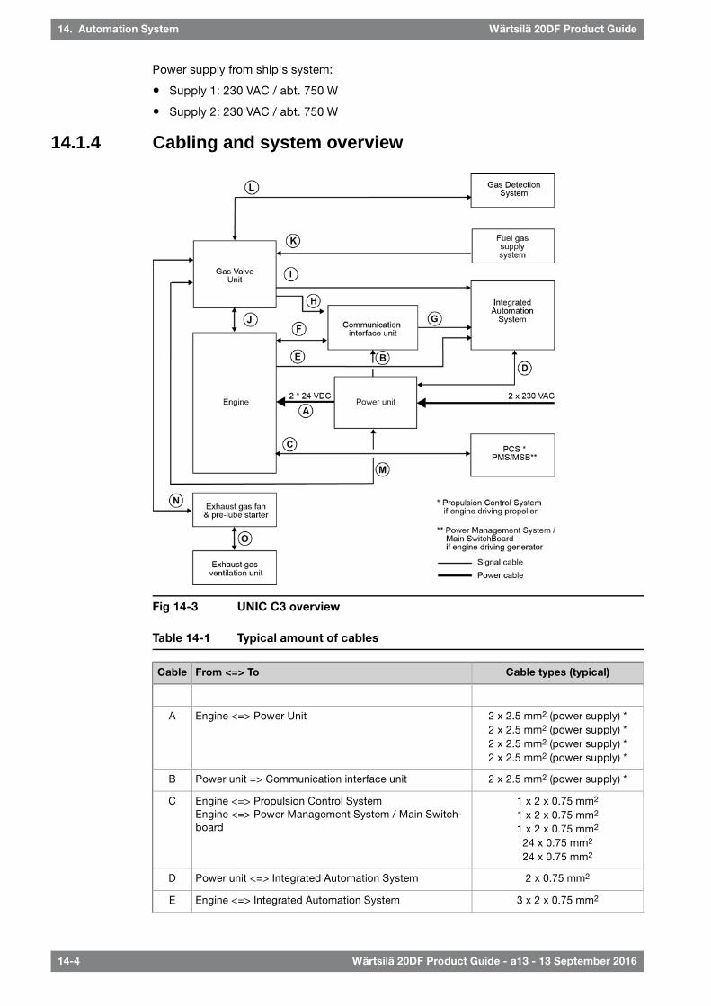
Power supply from ship's system:
● Supply 1: 230 VAC / abt. 750 W
● Supply 2: 230 VAC / abt. 750 W
14.1.4 Cabling and system overview
Fig 14-3 UNIC C3 overview
Table 14-1 Typical amount of cables
Cable types (typical)From <=> ToCable
2 x 2.5 mm2 (power supply) *2 x 2.5 mm2 (power supply) *2 x 2.5 mm2 (power supply) *2 x 2.5 mm2 (power supply) *
Engine <=> Power UnitA
2 x 2.5 mm2 (power supply) *Power unit => Communication interface unitB
1 x 2 x 0.75 mm2
1 x 2 x 0.75 mm2
1 x 2 x 0.75 mm2
24 x 0.75 mm2
24 x 0.75 mm2
Engine <=> Propulsion Control SystemEngine <=> Power Management System / Main Switch-board
C
2 x 0.75 mm2Power unit <=> Integrated Automation SystemD
3 x 2 x 0.75 mm2Engine <=> Integrated Automation SystemE
14-4 Wärtsilä 20DF Product Guide - a13 - 13 September 2016
Wärtsilä 20DF Product Guide14. Automation System

Cable types (typical)From <=> ToCable
1 x Ethernet CAT 5Engine => Communication interface unitF
1 x Ethernet CAT 5Communication interface unit => Integrated automationsystem
G
1 x Ethernet CAT 5Gas valve unit => Communication interface unitH
2 x 2 x 0.75 mm2
1 x Ethernet CAT5Gas Valve Unit <=> Integrated Automation SystemI
4 x 2 x 0.75 mm2
2 x 2 x 0.75 mm2
3 x 2 x 0.75 mm2
Engine <=> Gas Valve UnitJ
4 x 2 x 0.75 mm2Gas Valve Unit <=> Fuel gas supply systemK
1 x 2 x 0.75 mm2Gas Valve Unit <=> Gas detection systemL
2 x 2.5 mm2 (power supply) *2 x 2.5 mm2 (power supply) *
3 x 2 x 0.75 mm2
Power unit <=> Gas Valve UnitM
3 x 2 x 0.75 mm2
2 x 5 x 0.75 mm2Gas Valve Unit <=> Exhaust gas fan and pre-lube starterN
4 x 2 x 0.75 mm2
3 x 2.5 x 2.5 mm2Exhaust gas fan and pre-lube starter <=> Exhaust gasventilation unit
O
NOTE
Cable types and grouping of signals in different cables will differ depending oninstallation.
* Dimension of the power supply cables depends on the cable length.
Power supply requirements are specified in section Power unit.
Wärtsilä 20DF Product Guide - a13 - 13 September 2016 14-5
14. Automation SystemWärtsilä 20DF Product Guide

Fig 14-4 Signal overview (Main engine)
14-6 Wärtsilä 20DF Product Guide - a13 - 13 September 2016
Wärtsilä 20DF Product Guide14. Automation System

Fig 14-5 Signal overview (Generating set)
14.2 Functions
14.2.1 Engine operating modesThe operator can select two different fuel operating modes:
● Gas operating mode (gas fuel + pilot fuel injection)
● Diesel operating mode (conventional diesel fuel injection + pilot fuel injection)
In addition, engine control and safety system or the blackout detection system can force theengine to run in backup operating mode (conventional diesel fuel injection only).
It is possible to transfer a running engine from gas- into diesel operating mode. Below a certainload limit the engine can be transferred from diesel- into gas operating mode. The engine willautomatically trip from gas- into diesel operating mode (gas trip) in several alarm situations.Request for diesel operating mode will always override request for gas operating mode.
Wärtsilä 20DF Product Guide - a13 - 13 September 2016 14-7
14. Automation SystemWärtsilä 20DF Product Guide

The engine control system automatically forces the engine to backup operating mode(regardless of operator choice of operating mode) in two cases:
● Pilot fuel injection system related fault is detected (pilot trip)
● Engine is started while the blackout start mode signal (from external source) is active
Fig 14-6 Principle of engine operating modes
14.2.2 Start
14.2.2.1 Start blockingStarting is inhibited by the following functions:
● Stop lever in stop position
● Turning device engaged
● Pre-lubricating pressure low (override if black-out input is high and within last 30 minutesafter the pressure has dropped below the set point of 0.5 bar)
● Stop signal to engine activated (safety shut-down, emergency stop, normal stop)
● External start block active
● Exhaust gas ventilation not performed
● HFO selected or fuel oil temperature > 70°C (Gas mode only)
● Charge air shut-off valve closed (optional device)
14.2.2.2 Start in gas operating modeIf the engine is ready to start in gas operating mode the output signals "engine ready for gasoperation" (no gas trips are active) and "engine ready for start" (no start blockings are active)are activated. In gas operating mode the following tasks are performed automatically:
● A GVU gas leakage test
● The starting air is activated
● Pilot fuel injection and pilot fuel pressure control is enabled
● A combustion check (verify that all cylinders are firing)
● Gas admission is started and engine speed is raised to nominal
14-8 Wärtsilä 20DF Product Guide - a13 - 13 September 2016
Wärtsilä 20DF Product Guide14. Automation System

The start mode is interrupted in case of abnormalities during the start sequence. The startsequence takes about 1.5 minutes to complete.
14.2.2.3 Start in diesel operating modeWhen starting an engine in diesel operating mode the GVU check is omitted. The pilotcombustion check is performed to ensure correct functioning of the pilot fuel injection in orderto enable later transfer into gas operating mode. The start sequence takes about one minuteto complete.
14.2.2.4 Start in blackout modeWhen the blackout signal is active, the engine will be started in backup operating mode. Thestart is performed similarly to a conventional diesel engine, i.e. after receiving start signal theengine will start and ramp up to nominal speed using only the conventional diesel fuel system.The blackout signal disables some of the start blocks to get the engine running as quickly aspossible. All checks during start-up that are related to gas fuel system or pilot fuel system areomitted. Therefore the engine is not able to transfer from backup operating mode to gas- ordiesel operating mode before the gas and pilot system related safety measures have beenperformed. This is done by stopping the engine and re-starting it in diesel- or gas operatingmode.
After the blackout situation is over (i.e. when the first engine is started in backup operatingmode, connected to switchboard, loaded, and consequently blackout-signal cleared), moreengines should be started, and the one running in backup mode stopped and re-started ingas- or diesel operating mode.
14.2.3 Gas/diesel transfer control
14.2.3.1 Transfer from gas- to diesel-operating modeThe engine will transfer from gas to diesel operating mode at any load within 1s. This can beinitiated in three different ways: manually, by the engine control system or by the gas safetysystem (gas operation mode blocked).
14.2.3.2 Transfer from diesel- to gas-operating modeThe engine can be transferred to gas at engine load below 80% in case no gas trips are active,no pilot trip has occurred and the engine was not started in backup operating mode (excludingcombustion check).
Fuel transfers to gas usually takes about 2 minutes to complete, in order to minimizedisturbances to the gas fuel supply systems.
The engine can run in backup operating mode in case the engine has been started with theblackout start input active or a pilot trip has occurred. A transfer to gas operating mode canonly be done after a combustion check, which is done by restarting the engine.
A leakage test on the GVU is automatically done before each gas transfer.
Wärtsilä 20DF Product Guide - a13 - 13 September 2016 14-9
14. Automation SystemWärtsilä 20DF Product Guide

Fig 14-7 Operating modes are load dependent
14.2.3.3 Points for consideration when selecting fuelsWhen selecting the fuel operating mode for the engine, or before transferring between operatingmodes, the operator should consider the following:
● To prevent an overload of the gas supply system, transfer one engine at a time to gasoperating mode
● Before a transfer command to gas operating mode is given to an engine, the PMS oroperator must ensure that the other engines have enough ‘spinning reserve’ during thetransfers. This because the engine may need to be unloaded below the upper transfer limitbefore transferring
● If engine load is within the transfer window, the engine will be able to switch fuels withoutunloading
● Whilst an engine is transferring, the starting and stopping of heavy electric consumersshould be avoided
14.2.4 Stop, shutdown and emergency stop
14.2.4.1 Stop modeBefore stopping the engine, the control system shall first unload the engine slowly (if the engineis loaded), and after that open the generator breaker and send a stop signal to the engine.
Immediately after the engine stop signal is activated in gas operating mode, the GVU performsgas shut-off and ventilation. The pilot injection is active during the first part of the decelerationin order to ensure that all gas remaining in engine is burned.
In case the engine has been running on gas within two minutes prior to the stop the exhaustgas system is ventilated to discharge any unburned gas.
14.2.4.2 Shutdown modeShutdown mode is initiated automatically as a response to measurement signals.
In shutdown mode the clutch/generator breaker is opened immediately without unloading.The actions following a shutdown are similar to normal engine stop.
Shutdown mode must be reset by the operator and the reason for shutdown must beinvestigated and corrected before re-start.
14-10 Wärtsilä 20DF Product Guide - a13 - 13 September 2016
Wärtsilä 20DF Product Guide14. Automation System

14.2.4.3 Emergency stop modeThe sequence of engine stopping in emergency stop mode is similar to shutdown mode,except that also the pilot fuel injection is de-activated immediately upon stop signal.
Emergency stop is the fastest way of manually shutting down the engine. In case the emergencystop push-button is pressed, the button is automatically locked in pressed position.
To return to normal operation the push button must be pulled out and alarms acknowledged.
14.2.5 Speed control
14.2.5.1 Main engines (mechanical propulsion)The electronic speed control is integrated in the engine automation system.
The remote speed setting from the propulsion control is an analogue 4-20 mA signal. It is alsopossible to select an operating mode in which the speed reference can be adjusted withincrease/decrease signals.
The electronic speed control handles load sharing between parallel engines, fuel limiters, andvarious other control functions (e.g. ready to open/close clutch, speed filtering). Overloadprotection and control of the load increase rate must however be included in the propulsioncontrol as described in the chapter "Operating ranges".
For single main engines a fuel rack actuator with a mechanical-hydraulic backup governor isspecified. Mechanical back-up can also be specified for twin screw vessels with one engineper propeller shaft. Mechanical back-up is not an option in installations with two enginesconnected to the same reduction gear.
14.2.5.2 Generating setsThe electronic speed control is integrated in the engine automation system.
The load sharing can be based on traditional speed droop, or handled independently by thespeed control units without speed droop. The later load sharing principle is commonly referredto as isochronous load sharing. With isochronous load sharing there is no need for loadbalancing, frequency adjustment, or generator loading/unloading control in the external controlsystem.
In a speed droop system each individual speed control unit decreases its internal speedreference when it senses increased load on the generator. Decreased network frequency withhigher system load causes all generators to take on a proportional share of the increased totalload. Engines with the same speed droop and speed reference will share load equally. Loadingand unloading of a generator is accomplished by adjusting the speed reference of the individualspeed control unit. The speed droop is normally 4%, which means that the difference infrequency between zero load and maximum load is 4%.
In isochronous mode the speed reference remains constant regardless of load level. Bothisochronous load sharing and traditional speed droop are standard features in the speedcontrol and either mode can be easily selected. If the ship has several switchboard sectionswith tie breakers between the different sections, then the status of each tie breaker is requiredfor control of the load sharing in isochronous mode.
14.3 Alarm and monitoring signalsRegarding sensors on the engine, please see the internal P&I diagrams in this product guide.The actual configuration of signals and the alarm levels are found in the project specificdocumentation supplied for all contracted projects.
Wärtsilä 20DF Product Guide - a13 - 13 September 2016 14-11
14. Automation SystemWärtsilä 20DF Product Guide

14.4 Electrical consumers
14.4.1 Motor starters and operation of electrically driven pumpsSeparators, preheaters, compressors and fuel feed units are normally supplied aspre-assembled units with the necessary motor starters included. Various electrically drivenpumps require separate motor starters. Motor starters for electrically driven pumps are to bedimensioned according to the selected pump and electric motor.
Motor starters are not part of the control system supplied with the engine, but available asoptional delivery items.
14.4.1.1 Pre-lubricating oil pumpThe pre-lubricating oil pump must always be running when the engine is stopped. The pumpshall start when the engine stops, and stop when the engine starts. The engine control systemhandles start/stop of the pump automatically via a motor starter.
It is recommended to arrange a back-up power supply from an emergency power source.Diesel generators serving as the main source of electrical power must be able to resume theiroperation in a black out situation by means of stored energy. Depending on system designand classification regulations, it may be permissible to use the emergency generator.
For dimensioning of the pre-lubricating oil pump starter, the values indicated below can beused. For different voltages, the values may differ slightly.
Table 14-2 Electric motor ratings for pre-lubricating pump
Current [A]Power [kW]Frequency [Hz]Voltage [V]Engine type
6.03.0503 x 400Wärtsilä 20DF
6.23.5603 x 440
14.4.1.2 Exhaust gas ventilation unitThe exhaust gas ventilating unit is engine specific and includes an electric driven fan, flowswitch and closing valve. For further information, see chapter Exhaust gas system.
14.4.1.3 Gas valve unit (GVU)The gas valve unit is engine specific and controls the gas flow to the engine. The GVU isequipped with a built-on control system. For further information, see chapter Fuel system.
14.4.1.4 Stand-by pump, lubricating oil (if installed) (2P04)The engine control system starts the pump automatically via a motor starter, if the lubricatingoil pressure drops below a preset level when the engine is running. There is a dedicated sensoron the engine for this purpose.
The pump must not be running when the engine is stopped, nor may it be used forpre-lubricating purposes. Neither should it be operated in parallel with the main pump, whenthe main pump is in order.
14.4.1.5 Stand-by pump, HT cooling water (if installed) (4P03)The engine control system starts the pump automatically via a motor starter, if the coolingwater pressure drops below a preset level when the engine is running. There is a dedicatedsensor on the engine for this purpose.
14-12 Wärtsilä 20DF Product Guide - a13 - 13 September 2016
Wärtsilä 20DF Product Guide14. Automation System

14.4.1.6 Stand-by pump, LT cooling water (if installed) (4P05)The engine control system starts the pump automatically via a motor starter, if the coolingwater pressure drops below a preset level when the engine is running. There is a dedicatedsensor on the engine for this purpose.
14.4.1.7 Circulating pump for preheater (4P04)The preheater pump shall start when the engine stops (to ensure water circulation throughthe hot engine) and stop when the engine starts. The engine control system handles start/stopof the pump automatically via a motor starter.
Wärtsilä 20DF Product Guide - a13 - 13 September 2016 14-13
14. Automation SystemWärtsilä 20DF Product Guide

This page intentionally left blank

15. Foundation
Engines can be either rigidly mounted on chocks, or resiliently mounted on rubber elements.If resilient mounting is considered, Wärtsilä must be informed about existing excitations suchas propeller blade passing frequency. Dynamic forces caused by the engine are listed in thechapter Vibration and noise.
15.1 Steel structure designThe system oil tank may not extend under the reduction gear, if the engine is of dry sump typeand the oil tank is located beneath the engine foundation. Neither should the tank extendunder the support bearing, in case there is a PTO arrangement in the free end. The oil tankmust also be symmetrically located in transverse direction under the engine.
The foundation and the double bottom should be as stiff as possible in all directions to absorbthe dynamic forces caused by the engine, reduction gear and thrust bearing. The foundationshould be dimensioned and designed so that harmful deformations are avoided.
The foundation of the driven equipment must be integrated with the engine foundation.
15.2 Mounting of main engines
15.2.1 Rigid mountingMain engines can be rigidly mounted to the foundation either on steel chocks or resin chocks.
Prior to installation the shipyard must send detailed plans and calculations of the chockingarrangement to the classification society and to Wärtsilä for approval.
The engine has four feet integrated to the engine block. There are two Ø22 mm holes for M20holding down bolts and a threaded M16 hole for a jacking screw in each foot. The Ø22 holesin the seating top plate for the holding down bolts can be drilled though the holes in the enginefeet. In order to avoid bending stress in the bolts and to ensure proper fastening, the contactface underneath the seating top plate should be counterbored.
Holding down bolts are through-bolts with lock nuts. Selflocking nuts are acceptable, but hotdip galvanized bolts should not be used together with selflocking (nyloc) nuts. Two of theholding down bolts are fitted bolts and the rest are clearance (fixing) bolts. The fixing boltsare M20 8.8 bolts according DIN 931, or equivalent. The two Ø23 H7/m6 fitted bolts are locatedclosest to the flywheel, one on each side of the engine. The fitted bolts must be designed andinstalled so that a sufficient guiding length in the seating top plate is achieved, if necessaryby installing a distance sleeve between the seating top plate and the lower nut. The guidinglength in the seating top plate should be at least equal to the bolt diameter. The fitted boltsshould be made from a high strength steel, e.g. 42CrMo4 or similar and the bolt should havea reduced shank diameter above the guiding part in order to ensure a proper elongation. Therecommended shank diameter for the fitted bolts is 17 mm.
The tensile stress in the bolts is allowed to be max. 80% of the material yield strength and theequivalent stress during tightening should not exceed 90% of the yield strength.
Lateral supports must be installed for all engines. One pair of supports should be located atthe free end and one pair (at least) near the middle of the engine. The lateral supports are tobe welded to the seating top plate before fitting the chocks. The wedges in the supports areto be installed without clearance, when the engine has reached normal operating temperature.The wedges are then to be secured in position with welds. An acceptable contact surfacemust be obtained on the wedges of the supports.
Wärtsilä 20DF Product Guide - a13 - 13 September 2016 15-1
15. FoundationWärtsilä 20DF Product Guide

15.2.1.1 Resin chocksThe recommended dimensions of resin chocks are 150 x 400 mm. The total surface pressureon the resin must not exceed the maximum value, which is determined by the type of resinand the requirements of the classification society. It is recommended to select a resin thathas a type approval from the relevant classification society for a total surface pressure of 5N/mm2. (A typical conservative value is ptot 3.5 N/mm2).
During normal conditions, the support face of the engine feet has a maximum temperature ofabout 75°C, which should be considered when selecting the type of resin.
The bolts must be made as tensile bolts with a reduced shank diameter to ensure sufficientelongation since the bolt force is limited by the permissible surface pressure on the resin. Fora given bolt diameter the permissible bolt tension is limited either by the strength of the boltmaterial (max. stress 80% of the yield strength), or by the maximum permissible surfacepressure on the resin.
15.2.1.2 Steel chocksThe top plates of the foundation girders are to be inclined outwards with regard to the centreline of the engine. The inclination of the supporting surface should be 1/100 and it should bemachined so that a contact surface of at least 75% is obtained against the chocks.
Recommended size of the chocks are 115 x 170 mm at the position of the fitted bolts (2 pieces)and 115 x 190 mm at the position of the fixing bolts (6 pieces). The design should be suchthat the chocks can be removed, when the lateral supports are welded to the foundation andthe engine is supported by the jacking screws. The chocks should have an inclination of 1:100(inwards with regard to the engine centre line). The cut out in the chocks for the fixing boltsshall be 24...26 mm (M20 bolts), while the hole in the chocks for the fitted bolts shall be drilledand reamed to the correct size (ø23 H7) when the engine is finally aligned to the reductiongear.
The design of the holding down bolts is shown in figure Chocking of main engines(3V69A0238C). The bolts are designed as tensile bolts with a reduced shank diameter toachieve a large elongation, which improves the safety against loosening of the nuts.
15.2.1.3 Steel chocks with adjustable heightAs an alternative to resin chocks or conventional steel chocks it is also permitted to install theengine on adjustable steel chocks. The chock height is adjustable between 30...50 mm forthe approved type of chock. There must be a chock of adequate size at the position of eachholding down bolt.
15-2 Wärtsilä 20DF Product Guide - a13 - 13 September 2016
Wärtsilä 20DF Product Guide15. Foundation

Fig 15-1 Main engine seating, view from above (DAAF015003)
Dimensions [mm]Engine
ZLHGFEDCBA
1552080207019601660153059046016050W 6L20DF
1552680237022601960183059046016050W 8L20DF
1552980267025602260213059046016050W 9L20DF
Fig 15-2 Main engine seating,end view (DAAF015003)
(D) Dry sump[mm]
(D) Wet sump[mm]
(D) Deep sump[mm]
Enginetype
3003005006L
3003005008L
3003005009L
Wärtsilä 20DF Product Guide - a13 - 13 September 2016 15-3
15. FoundationWärtsilä 20DF Product Guide

Fig 15-3 Chocking of main engines (3V69A0238C)
15-4 Wärtsilä 20DF Product Guide - a13 - 13 September 2016
Wärtsilä 20DF Product Guide15. Foundation

15.2.2 Resilient mountingIn order to reduce vibrations and structure borne noise, main engines can be resiliently mountedon rubber mounts. The transmission of forces emitted by a resiliently mounted engine is10-20% compared to a rigidly mounted engine.
(D) Dry sump[mm]
(D) Wet sump[mm]
(D) Deep sump[mm]
Enginetype
6256258256L
6256258258L
6256258259L
Fig 15-4 Resilient mounting(DAAF017144)
Wärtsilä 20DF Product Guide - a13 - 13 September 2016 15-5
15. FoundationWärtsilä 20DF Product Guide

15.3 Mounting of generating sets
15.3.1 Generator feet design
Fig 15-5 Instructions for designing the feet of the generator and the distancebetween its holding down bolt (4V92F0134E)
15.3.2 Resilient mountingGenerating sets, comprising engine and generator mounted on a common base frame, areusually installed on resilient mounts on the foundation in the ship.
The resilient mounts reduce the structure borne noise transmitted to the ship and also serveto protect the generating set bearings from possible fretting caused by hull vibration.
The number of mounts and their location is calculated to avoid resonance with excitationsfrom the generating set engine, the main engine and the propeller.
NOTE
To avoid induced oscillation of the generating set, the following data must be sentby the shipyard to Wärtsilä at the design stage:
● main engine speed [rpm] and number of cylinders
● propeller shaft speed [rpm] and number of propeller blades
The selected number of mounts and their final position is shown in the generating set drawing.
15-6 Wärtsilä 20DF Product Guide - a13 - 13 September 2016
Wärtsilä 20DF Product Guide15. Foundation

Fig 15-6 Recommended design of the generating set seating (3V46L0720G)
B*A*Engine type
1580 / 1730 / 18801330 / 1480 / 16306L
1730 / 18801480 / 16308L
1730 / 1880 / 21101480 / 1630 / 18609L
* Dependent on generator width
15.3.3 Rubber mountsThe generating set is mounted on conical resilient mounts, which are designed to withstandboth compression and shear loads. In addition the mounts are equipped with an internal bufferto limit movements of the generating set due to ship motions. Hence, no additional side orend buffers are required.
The rubber in the mounts is natural rubber and it must therefore be protected from oil, oilywater and fuel.
The mounts should be evenly loaded, when the generating set is resting on the mounts. Themaximum permissible variation in compression between mounts is 2.0 mm. If necessary,chocks or shims should be used to compensate for local tolerances. Only one shim is permittedunder each mount.
The transmission of forces emitted by the engine is 10-20% when using conical mounts.
Wärtsilä 20DF Product Guide - a13 - 13 September 2016 15-7
15. FoundationWärtsilä 20DF Product Guide

Fig 15-7 Rubber mounts (3V46L0706C)
15.4 Flexible pipe connectionsWhen the engine or the generating set is resiliently installed, all connections must be flexibleand no grating nor ladders may be fixed to the generating set. When installing the flexible pipeconnections, unnecessary bending or stretching should be avoided. The external pipe mustbe precisely aligned to the fitting or flange on the engine. It is very important that the pipeclamps for the pipe outside the flexible connection must be very rigid and welded to the steelstructure of the foundation to prevent vibrations, which could damage the flexible connection.
15-8 Wärtsilä 20DF Product Guide - a13 - 13 September 2016
Wärtsilä 20DF Product Guide15. Foundation

16. Vibration and Noise
Wärtsilä 20DF generating sets comply with vibration levels according to ISO 8528-9. Mainengines comply with vibration levels according to ISO 10816-6 Class 5.
16.1 External forces and couplesSome cylinder configurations produce external forces and couples. These are listed in thetables below.
The ship designer should avoid natural frequencies of decks, bulkheads and superstructuresclose to the excitation frequencies. The double bottom should be stiff enough to avoidresonances especially with the rolling frequencies.
Fig 16-1 Coordinate system
Table 16-1 External forces
FZ[kNm]
FY[kNm]
Fre-quency[Hz]
FZ[kNm]
FY[kNm]
Fre-quency[Hz]
FZ[kNm]
FY[kNm]
Fre-quency[Hz]
Speed[rpm]
Engine
––
––
––
––
––
––
––
––
––
10001200
W 6L20DF
––
––
––
––
––
––
34
––
6780
10001200
W 8L20DF
––
––
––
––
––
––
––
––
––
10001200
W 9L20DF
Wärtsilä 20DF Product Guide - a13 - 13 September 2016 16-1
16. Vibration and NoiseWärtsilä 20DF Product Guide

Table 16-2 External couples
MZ[kNm]
MY[kNm]
Fre-quency[Hz]
MZ[kNm]
MY[kNm]
Fre-quency[Hz]
MZ[kNm]
MY[kNm]
Fre-quency[Hz]
Speed[rpm]
Engine
––
––
––
––
––
––
––
––
––
10001200
W 6L20DF
––
––
––
––
––
––
––
––
––
10001200
W 8L20DF
––
11
6780
––
68
3340
812
812
1720
10001200
W 9L20DF
– couples are zero or insignificant.
16-2 Wärtsilä 20DF Product Guide - a13 - 13 September 2016
Wärtsilä 20DF Product Guide16. Vibration and Noise

16.2 Torque variations
Table 16-3 Torque variation at 100% load
MX[kNm]
Frequency[Hz]
MX[kNm]
Frequency[Hz]
MX[kNm]
Frequency[Hz]
Speed[rpm]
Engine
12
150180
55
100120
63
5060
10001200
W 6L20DF
11
200240
33
133160
1313
6780
10001200
W 8L20DF
11
225270
23
150180
1314
7590
10001200
W 9L20DF
16.3 Mass moments of inertiaThe mass-moments of inertia of the main engines (including flywheel) are typically as follows:
J [kgm²]Engine
90...150W 6L20DF
110...160W 8L20DF
100...170W 9L20DF
16.4 Air borne noiseThe airborne noise of the engine is measured as a sound power level according to ISO 9614-2.Noise level is given as sound power emitted by the whole engine, reference level 1 pW. Thevalues presented in the graphs below are typical values, cylinder specific graphs are includedin the Installation Planning Instructions (IPI) delivered for all contracted projects.
Fig 16-2 Sound power level for engine noise
Wärtsilä 20DF Product Guide - a13 - 13 September 2016 16-3
16. Vibration and NoiseWärtsilä 20DF Product Guide

16.5 Exhaust noiseThe exhaust noise of the engine is measured as the sound power emitted from the turbochargeroutlet without exhaust gas piping connected. Reference value 1 pW. The values presented inthe graphs below are typical values, cylinder specific graphs are included in the InstallationPlanning Instructions (IPI) delivered for all contracted projects.
Fig 16-3 Sound power level for exhaust noise
16-4 Wärtsilä 20DF Product Guide - a13 - 13 September 2016
Wärtsilä 20DF Product Guide16. Vibration and Noise

17. Power Transmission
17.1 Flexible couplingThe power transmission of propulsion engines is accomplished through a flexible coupling ora combined flexible coupling and clutch mounted on the flywheel. The crankshaft is equippedwith an additional shield bearing at the flywheel end. Therefore also a rather heavy couplingcan be mounted on the flywheel without intermediate bearings.
The type of flexible coupling to be used has to be decided separately in each case on thebasis of the torsional vibration calculations.
In case of two bearing type generator installations a flexible coupling between the engine andthe generator is required.
17.1.1 Connection to generator
Fig 17-1 Connection engine/single bearing generator (2V64L0071B)
Wärtsilä 20DF Product Guide - a13 - 13 September 2016 17-1
17. Power TransmissionWärtsilä 20DF Product Guide

Fig 17-2 Connection engine/two-bearing generator (4V64F0001B)
Dimensions [mm]Engine
min DKLD1
160180190150W 6L20DF
160180190150W 8L20DF
160180190150W 9L20DF
17.2 Torque flangeIn mechanical propulsion applications, a torque meter has to be installed in order to measurethe absorbed power. The torque flange has an installation length of 160 mm for all cylinderconfigurations and is installed after the flexible coupling.
17.3 ClutchIn dual fuel engine installations with mechanical drive, it must be possible to disconnect thepropeller shaft from the engine by using a clutch. The use of multiple plate hydraulicallyactuated clutches built into the reduction gear is recommended.
A clutch is also required when two or more engines are connected to the same driven machinerysuch as a reduction gear.
To permit maintenance of a stopped engine clutches must be installed in twin screw vesselswhich can operate on one shaft line only.
17.4 Shaft locking deviceA shaft locking device should also be fitted to be able to secure the propeller shaft in positionso that wind milling is avoided. This is necessary because even an open hydraulic clutch cantransmit some torque. Wind milling at a low propeller speed (<10 rpm) can due to poorlubrication cause excessive wear of the bearings.
The shaft locking device can be either a bracket and key or an easier to use brake disc withcalipers. In both cases a stiff and strong support to the ship’s construction must be provided.
A shaft locking device should be fitted to be able to secure the propeller shaft in position sothat wind milling is avoided. This is necessary because even an open hydraulic clutch cantransmit some torque. Wind milling at a low propeller speed (<10 rpm) can due to poorlubrication cause excessive wear of the bearings.
The shaft locking device can be either a bracket and key or an easier to use brake disc withcalipers. In both cases a stiff and strong support to the ship’s construction must be provided.
17-2 Wärtsilä 20DF Product Guide - a13 - 13 September 2016
Wärtsilä 20DF Product Guide17. Power Transmission

Fig 17-3 Shaft locking device and brake disc with calipers
17.5 Power-take-off from the free endAt the free end a shaft connection as a power take off can be provided. If required full outputcan be taken from the PTO shaft.
Fig 17-5 PTOalternative 2 (DAAE079045)Fig 17-4 PTO alternative 1(DAAE079074A)
Dimensions [mm]Rating [kW] 1)
FECBAD2D1
1082809708606101701001700 1)
1183009908806301851102200 1)
Dimensions [mm]Rating [kW]
AD1
10580700 1)
1501202300 1)
External support bearing is not possible for resiliently mounted engines.Rating is dependent on coupling hub. Max. output mayalso be restricted due to max coupling weight 135 kg.1320 kW always accepted.
1) PTO shaft design rating, engine output may be lower
Wärtsilä 20DF Product Guide - a13 - 13 September 2016 17-3
17. Power TransmissionWärtsilä 20DF Product Guide

17.6 Input data for torsional vibration calculationsA torsional vibration calculation is made for each installation. For this purpose exact data ofall components included in the shaft system are required. See list below.
Installation
● Classification
● Ice class
● Operating modes
Reduction gear
A mass elastic diagram showing:
● All clutching possibilities
● Sense of rotation of all shafts
● Dimensions of all shafts
● Mass moment of inertia of all rotating parts including shafts and flanges
● Torsional stiffness of shafts between rotating masses
● Material of shafts including tensile strength and modulus of rigidity
● Gear ratios
● Drawing number of the diagram
Propeller and shafting
A mass-elastic diagram or propeller shaft drawing showing:
● Mass moment of inertia of all rotating parts including the rotating part of the OD-box, SKFcouplings and rotating parts of the bearings
● Mass moment of inertia of the propeller at full/zero pitch in water
● Torsional stiffness or dimensions of the shaft
● Material of the shaft including tensile strength and modulus of rigidity
● Drawing number of the diagram or drawing
Main generator or shaft generator
A mass-elastic diagram or an generator shaft drawing showing:
● Generator output, speed and sense of rotation
● Mass moment of inertia of all rotating parts or a total inertia value of the rotor, includingthe shaft
● Torsional stiffness or dimensions of the shaft
● Material of the shaft including tensile strength and modulus of rigidity
● Drawing number of the diagram or drawing
Flexible coupling/clutch
If a certain make of flexible coupling has to be used, the following data of it must be informed:
● Mass moment of inertia of all parts of the coupling
● Number of flexible elements
● Linear, progressive or degressive torsional stiffness per element
● Dynamic magnification or relative damping
● Nominal torque, permissible vibratory torque and permissible power loss
● Drawing of the coupling showing make, type and drawing number
17-4 Wärtsilä 20DF Product Guide - a13 - 13 September 2016
Wärtsilä 20DF Product Guide17. Power Transmission

Operational data
● Operational profile (load distribution over time)
● Clutch-in speed
● Power distribution between the different users
● Power speed curve of the load
17.7 Turning gearThe engine can be turned with a manual ratchet tool after engaging a gear wheel on the flywheelgear rim. The ratchet tool is provided with the engine.
Wärtsilä 20DF Product Guide - a13 - 13 September 2016 17-5
17. Power TransmissionWärtsilä 20DF Product Guide

This page intentionally left blank

18. Engine Room Layout
18.1 Crankshaft distancesMinimum crankshaft distances have to be followed in order to provide sufficient space betweenengines for maintenance and operation.
18.1.1 Main engines
Fig 18-1 Crankshaft distances main engines (DAAF017589)
DCBAEngine
1845120010001800W 6L20DF
1845120013001800W 8L20DF
1845120013001800W 9L20DF
All dimensions in mm.
A - Minimum height when removing a piston
B - Camshaft overhaul distance
C - Charge air cooler overhaul distance
D - Space necessary for access to the connection box
Wärtsilä 20DF Product Guide - a13 - 13 September 2016 18-1
18. Engine Room LayoutWärtsilä 20DF Product Guide

18.1.2 Generating sets
Fig 18-2 Crankshaft distances generating sets (DAAE007434C)
F**E*Engine type
1270 / 14201970 / 2020W 6L20DF
14202020W 8L20DF
1420 / 15702020 / 2170W 9L20DF
* Depends on common base frame, ** Depends on the width of the generatorAll dimensions in mm.
18-2 Wärtsilä 20DF Product Guide - a13 - 13 September 2016
Wärtsilä 20DF Product Guide18. Engine Room Layout
18.2 Space requirements for maintenance
18.2.1 Working space around the engineThe required working space around the engine is mainly determined by the dismountingdimensions of engine components, and space requirement of some special tools. It is especiallyimportant that no obstructive structures are built next to engine driven pumps, as well ascamshaft and crankcase doors.
However, also at locations where no space is required for dismounting of engine parts, aminimum of 1000 mm free space is recommended for maintenance operations everywherearound the engine.
18.2.2 Engine room height and lifting equipmentThe required engine room height is determined by the transportation routes for engine parts.If there is sufficient space in transverse and longitudinal direction, there is no need to transportengine parts over the rocker arm covers or over the exhaust pipe and in such case thenecessary height is minimized.
Separate lifting arrangements are usually required for overhaul of the turbocharger since thecrane travel is limited by the exhaust pipe. A chain block on a rail located over the turbochargeraxis is recommended.
18.2.3 Maintenance platformsIn order to enable efficient maintenance work on the engine, it is advised to build themaintenance platforms on recommended elevations. The width of the platforms should be atminimum 800 mm to allow adequate working space. The surface of maintenance platformsshould be of non-slippery material (grating or chequer plate).
18.3 Transportation and storage of spare parts and toolsTransportation arrangement from engine room to storage and workshop has to be preparedfor heavy engine components. This can be done with several chain blocks on rails oralternatively utilising pallet truck or trolley. If transportation must be carried out using severallifting equipment, coverage areas of adjacent cranes should be as close as possible to eachother.
Engine room maintenance hatch has to be large enough to allow transportation of maincomponents to/from engine room.
It is recommended to store heavy engine components on slightly elevated adaptable surfacee.g. wooden pallets. All engine spare parts should be protected from corrosion and excessivevibration.
On single main engine installations it is important to store heavy engine parts close to theengine to make overhaul as quick as possible in an emergency situation.
18.4 Required deck area for service workDuring engine overhaul some deck area is required for cleaning and storing dismantledcomponents. Size of the service area is dependent of the overhauling strategy chosen, e.g.one cylinder at time, one bank at time or the whole engine at time. Service area should beplain steel deck dimensioned to carry the weight of engine parts.
Wärtsilä 20DF Product Guide - a13 - 13 September 2016 18-3
18. Engine Room LayoutWärtsilä 20DF Product Guide

18.4.1 Service space requirement
18.4.1.1 Service space for engines with turbocharger in driving end
Fig 18-3 Service space for engineswith turbocharger in driving end (1V69C0301C)
9L8L6LService spaces in mm
1800Height for overhauling piston and connecting rodA1
2300Height for transporting piston and conn rod freely over adjacent cyl head coversA2
240024002300Height for transporting piston and conn rod freely over exhaust gas insulation boxA3
1200Width for dismantling charge air cooler and air inlet box sideways by using lifting toolB1
1580Height of the lifting eye for the charge air cooler lifting toolB2
390Recommended lifting point for charge air cooler lifting toolB3
590Recommended lifting point for charge air cooler lifting toolB4
800 / 560Removal of main bearing side screw, flexible / rigid mountingC1
635Distance needed for dismantling lubricating oil and water pumpsD1
With PTO: lenght + 515Without PTO: 650
Distance needed for dismantling pump cover with fitted pumpsE1
710710650The recommended axial clearance for dismantling and assembly of silencers. Minimumaxial clearance: 100 mm (F2)
F1
11701170990Recommended distance for dismantling the gas outlet elbowF3
300Recommended lifting point for the turbochargerG1
345Recommended lifting point sideways for the turbochargerG2
1250Width for dismantling lubricating oil module and/or plate coolerH1
445Recommended lifting point for dismantling lubricating oil module and/or plate coolerH2
1045Recommended lifting point sideways for dismantling lube oil module and/or platecooler
H3
130013001000Camshaft overhaul distance (free end)I1
130013001000Camshaft overhaul distance (flywheel end)I2
1783Space necessary for access to the connection boxJ1
18-4 Wärtsilä 20DF Product Guide - a13 - 13 September 2016
Wärtsilä 20DF Product Guide18. Engine Room Layout

18.4.1.2 Service space for engines with turbocharger in free end
Fig 18-4 Service space for engines with turbocharger in free end (1V69C0302C)
9L8L6LService spaces in mm
1800Height for overhauling piston and connecting rodA1
2300Height for transporting piston and connecting rod freely over adjacent cylinderhead covers
A2
240024002300Height for transporting piston and connecting rod freely over exhaust gas insulationbox
A3
1200Width for dismantling charge air cooler and air inlet box sideways by using liftingtool
B1
1580Height of the lifting eye for the charge air cooler lifting toolB2
550550550Recommended lifting point for charge air cooler lifting toolB3
560Recommended lifting point for charge air cooler lifting toolB4
800 / 560Removal of main bearing side screw, flexible / rigid mountingC1
635Distance for dismantling lubricating oil and water pumpD1
With PTO: lenght + 515Without PTO: 650
Distance for dismantling pump cover with fitted pumpsE1
750750650The recommended axial clearance for dismantling and assembly of silencers.Minimum axial clearance: 100 mm (F2)
F1
11201120990Recommended distance for dismantling the gas outlet elbowF3
350Recommended lifting point for the turbochargerG1
320Recommended lifting point sideways for the turbochargerG2
1250Width for dismantling lubricating oil module and/or plate coolerH1
445Recommended lifting point for dismantling lubricating oil module and/or platecooler
H2
1045Recommended lifting point sideways for dismantling lubricating oil module and/orplate cooler
H3
130013001000Camshaft overhaul distance (free end)I1
130013001000Camshaft overhaul distance (flywheel end)I2
1825Space necessery for access to the connection boxJ1
Wärtsilä 20DF Product Guide - a13 - 13 September 2016 18-5
18. Engine Room LayoutWärtsilä 20DF Product Guide

18.4.1.3 Service space for generating sets
Fig 18-5 Service space for generating sets (DAAE006367A)
9L8L6LService spaces in mm
1800Height for overhauling piston and connecting rodA1
2300Height for transporting piston and connecting rod freely over adjacent cylinderhead covers
A2
240024002300Height for transporting piston and connecting rod freely over exhaust gas insulationbox
A3
1200Width for dismantling charge air cooler and air inlet box sideways by using liftingtool
B1
1580Height of the lifting eye for the charge air cooler lifting toolB2
550550550Recommended lifting point for charge air cooler lifting toolB3
560Recommended lifting point for charge air cooler lifting toolB4
560Width for removing main bearing side screwC1
635Distance needed to dismantle lube oil and water pumpD1
650Distance needed to dismantle pump cover with fitted pumpsE1
750750650The recommended axial clearance for dismantling and assembly of silencers Min-imum axial clearance: 100 mm (F2)
F1
11201120990Recommended distance for dismantling the gas outlet elbowF3
350Recommended lifting point for the turbochargerG1
320Recommended lifting point sideways for the turbochargerG2
1250 (and/or plate cooler)Width for dismantling lube oil moduleH1
445 (and/or plate cooler)Recommended lifting point for dismantling lube oil moduleH2
1045 (and/or plate cooler)Recommended lifting point sideways for dismantling lube oil moduleH3
130013001000Camshaft overhaul distance (free end)I1
130013001000Camshaft overhaul distance (flywheel end)I2
1825Space necessary for access to the connection boxJ1
500Service space for generatorK1
18-6 Wärtsilä 20DF Product Guide - a13 - 13 September 2016
Wärtsilä 20DF Product Guide18. Engine Room Layout

19. Transport Dimensions and Weights
19.1 Lifting of main engines
Fig 19-1 Lifting of main engines (DAAF016244)
Wet sumpDry sumpL [mm]Engine type
B [mm]A [mm]B [mm]A [mm]
6756008246243200W 6L20DF
6756008246243500W 8L20DF
6756008246244100W 9L20DF
Wärtsilä 20DF Product Guide - a13 - 13 September 2016 19-1
19. Transport Dimensions and WeightsWärtsilä 20DF Product Guide

19.2 Lifting of generating sets
Fig 19-2 Lifting of generating sets (DAAF016285A)
19-2 Wärtsilä 20DF Product Guide - a13 - 13 September 2016
Wärtsilä 20DF Product Guide19. Transport Dimensions and Weights

19.3 Engine components
Table 19-1 Lubricating oil insert
Weight [kg]Dimensions [mm]Engine
LJH
100396896196W 6L20DF
125396896247W 8L20DF
140396896275W 9L20DF
Table 19-2 Charge air cooler insert
Weight [kg]Dimensions [mm]Engine
GED
160380345626W 6L20DF
160380345626W 8L20DF
160380345626W 9L20DF
Table 19-3 Turbocharger
Weight (kg)Dimensions [mm]Engine
CBA
2155686361097W 6L20DF
3406757601339W 8L20DF
3406677731339W 9L20DF
Wärtsilä 20DF Product Guide - a13 - 13 September 2016 19-3
19. Transport Dimensions and WeightsWärtsilä 20DF Product Guide

Fig 19-3 Major spare parts (DAAF022165)
Weight[kg]
DescriptionNoWeight[kg]
DescriptionNoWeight[kg]
DescriptionNo
1.4Main bearing shell90.8Valve539Connecting rod1
11.4Small intermediate gear100.2Piston ring628.5Piston2
23.5Large intermediate gear1127Injection pump742Cylinder liner3
25Camshaft drive gear123.2Injection valve889Cylinder head4
19-4 Wärtsilä 20DF Product Guide - a13 - 13 September 2016
Wärtsilä 20DF Product Guide19. Transport Dimensions and Weights

20. Product Guide Attachments
This and other product guides can be accessed on the internet, from the Business OnlinePortal at www.wartsila.com. Product guides are available both in web and PDF format. Drawingsare available in PDF and DXF format, and in near future also as 3D models. Consult your salescontact at Wärtsilä to get more information about the product guides on the Business OnlinePortal.
The attachments are not available in the printed version of the product guide.
Wärtsilä 20DF Product Guide - a13 - 13 September 2016 20-1
20. Product Guide AttachmentsWärtsilä 20DF Product Guide

This page intentionally left blank

21. ANNEX
21.1 Unit conversion tablesThe tables below will help you to convert units used in this product guide to other units. Wherethe conversion factor is not accurate a suitable number of decimals have been used.
Mass conversion factorsLength conversion factors
Multiply byToConvert fromMultiply byToConvert from
2.205lbkg0.0394inmm
35.274ozkg0.00328ftmm
Volume conversion factorsPressure conversion factors
Multiply byToConvert fromMultiply byToConvert from
61023.744in3m30.145psi (lbf/in2)kPa
35.315ft3m320.885lbf/ft2kPa
219.969Imperial gallonm34.015inch H2OkPa
264.172US gallonm30.335foot H2OkPa
1000l (litre)m3101.972mm H2OkPa
0.01barkPa
Moment of inertia and torque conversion factorsPower conversion
Multiply byToConvert fromMultiply byToConvert from
23.730lbft2kgm21.360hp (metric)kW
737.562lbf ftkNm1.341US hpkW
Flow conversion factorsFuel consumption conversion factors
Multiply byToConvert fromMultiply byToConvert from
4.403US gallon/minm3/h (liquid)0.736g/hphg/kWh
0.586ft3/minm3/h (gas)0.00162lb/hphg/kWh
Density conversion factorsTemperature conversion factors
Multiply byToConvert fromMultiply byToConvert from
0.00834lb/US gallonkg/m3F = 9/5 *C + 32F°C
0.01002lb/Imperial gallonkg/m3K = C + 273.15K°C
0.0624lb/ft3kg/m3
21.1.1 Prefix
Table 21-1 The most common prefix multipliers
FactorSymbolNameFactorSymbolNameFactorSymbolName
10-9nnano103kkilo1012Ttera
10-3mmilli109Ggiga
10-6μmicro106Mmega
Wärtsilä 20DF Product Guide - a13 - 13 September 2016 21-1
21. ANNEXWärtsilä 20DF Product Guide

21.2 Collection of drawing symbols used in drawings
Fig 21-1 List of symbols (DAAE000806c)
21-2 Wärtsilä 20DF Product Guide - a13 - 13 September 2016
Wärtsilä 20DF Product Guide21. ANNEX


WÄRTSILÄ® is a registered trademark. Copyright © 2011 Wärtsilä Corporation.
02.2
011
/ B
ock´
s O
ffice
Wärtsilä is a global leader in complete lifecycle power solutions
for the marine and energy markets. By emphasising technological
innovation and total efficiency, Wärtsilä maximises the environmental
and economic performance of the vessels and power plants of its
customers. Wärtsilä is listed on the NASDAQ OMX Helsinki, Finland.


![Wärtsilä HY - Genoa Shipping Week · REFERENCE WÄRTSILÄ HY 27 250 kWh WÄRTSILÄ HY 27 750 kWh WÄRTSILÄ HY 20 1000 kWh Main engines 2x W8L26 [2x 2720kW] 2x W8L26 [2x 2720kW]](https://static.fdocuments.us/doc/165x107/5b78ad217f8b9a7f378c08e5/waertsilae-hy-genoa-shipping-reference-waertsilae-hy-27-250-kwh-waertsilae.jpg)