
W Version 1.4 January 2018 · Omni-Stop Super Duty Security Bollard is essential to ... The test...
14
Transcript of W Version 1.4 January 2018 · Omni-Stop Super Duty Security Bollard is essential to ... The test...
W www.saferoads.com.au T +61 3 5945 6600 E [email protected]
Version 1.4
January 2018
Page 1
Contents Preface .............................................................................................................................................................................. 2
Introduction ...................................................................................................................................................................... 2
Crash Tests ........................................................................................................................................................................ 3
System Design ................................................................................................................................................................... 4
Installation Examples ........................................................................................................................................................ 6
Installation Drawing .......................................................................................................................................................... 7
Installation Procedure ....................................................................................................................................................... 8
Repairs and Maintenance ............................................................................................................................................... 11
Inspection and Test Plan ................................................................................................................................................. 12

W www.saferoads.com.au T +61 3 5945 6600 E [email protected]
Version 1.4
January 2018
Page 2
Preface Proper design, installation and maintenance of the
Omni-Stop Super Duty Security Bollard is essential to
ensure maximum performance.
It is critical for installers of the Omni-Stop Super Duty
Security Bollard to be fully familiar with this manual.
Take the time to review this manual thoroughly
before performing the necessary work.
If more information is required please contact
Saferoads:
Website: www.saferoads.com.au
Australia: 1800 060 672
USA: 859 469 0364
International: +61 3 5945 6600
Email: [email protected]
Introduction Saferoads Omni-Stop Super Duty Security Bollard has
been successfully crash tested to confirm it can stop a
5000lb/2270kg pickup travelling at 30mph/50kmh*.
The bollard must be installed in accordance with this
product manual and the enclosed minimum footing
requirements.
The test vehicle impacted the bollard in the centre of
the vehicle, the forward displacement of the
structural elements of the vehicle during the impact
was 2.7ft/825mm from the centre of the bollard,
when the footing is surrounded by 250mm concrete.
* Refer to NATA tests 21062-03 and 21062-04 on
18/9/2017 and 16/10/2017
Identification
The Omni-Stop Super Duty Security Bollard has been
crash tested, each bollard displays an identification
sticker as per the below image.

W www.saferoads.com.au T +61 3 5945 6600 E [email protected]
Version 1.4
January 2018
Page 3
Crash Tests The Omni-Stop Super Duty Security Bollard was crash
tested in September and October 2017, for full details
refer to NATA test reports 21062-03 and 21062-04.
In accordance with ASTM F3016M-14 Clause 9.5,
elements of the vehicle penetrated 2.7ft/825mm past
the bollard centre line during impact measured at the
vehicle bumper height giving the bollard a rating of
S30/P2.
See below extract from the test report, where the
vehicle penetrated 2.7ft/825mm past the centre of
the bollard during impact, when the bollard is
surrounded by 250mm thick concrete. It would be
desirable for designers to allow a conservative
3ft/900mm past the centre of the bollard for the
design clear zone when the top of the bollards footing
is supported by a concrete slab.
When surrounded by SP – poorly graded sand only,
vehicle penetrated 7.3ft/2200mm past the centre of
the bollard during impact. Therefore, designers should
allow a conservative 8ft/2500mm safe zone when
installed in weak soil with no structural support by a
concrete surface.

W www.saferoads.com.au T +61 3 5945 6600 E [email protected]
Version 1.4
January 2018
Page 4
System Design Note: A site-specific risk assessment should be
completed at each site to ensure the positioning of
the bollards meets the design brief and are fit for
purpose.
Crash testing has shown that the vehicle penetrates
past the bollard during an impact. The figure below
shows the recommended clear zone (3ft/900mm)
behind the centre of a bollard in the direction of the
impacting vehicle when the bollard is installed with
the top of the footing encased in a concrete slab.
When designing bollard arrays, or strings, the
direction of all potential impacting vehicles needs to
be considered to ensure the design is fit for purpose.
Typically, a minimum of 2 bollards are required to
protect an object as vehicles can impact the bollard
from varying angles. A single bollard has limited scope
as vehicles can pass the bollard on either side.
One bollard may reduce the potential of vehicle
impacts on the corner of a bridge abutment, however
the below layout is recommended to ensure the
abutment is properly protected.
Note the 3ft/900mm clear space between the centre
of the bollards and the “protected item”. The
potential angle of impact is set at 25 degrees, this can
be adjusted as required by the designer, considering
the likely angle of impact at the site.
The below figure shows the recommended minimum
spacing of 4.5ft/1350mm centres to prevent small
cars penetrating a string of bollards when impacting
perpendicular to the string. This is common when
strings of bollards are installed at the end of a “T”
intersection.

W www.saferoads.com.au T +61 3 5945 6600 E [email protected]
Version 1.4
January 2018
Page 5
Note at 6.5ft/2000mm bollard spacing at 25° impact
angle, the clear zone extends 3.5ft/1077mm
perpendicular to the string of bollards. While the
potential for vehicles to breach the string of bollards
would follow a saw tooth pattern, the 3.5ft/1077mm
clear zone offset should be applied to the entire
length of the bollard string.
The spacing of the bollards can be altered depending
on the design impact angle and allowable clear zone
behind the string of bollards.
It is recommended that the centre to centre spacings
be a maximum of 8.2ft/2500mm.
The figures below show how the clear zone is reduced
to 1.75ft/534mm if the design impact angle can be
reduced to 15 degrees, compared to 2.9ft/886mm
where the design impact angle was 25 degrees. Both
examples have the same bollard spacing at
5ft/1500mm.
W www.saferoads.com.au T +61 3 5945 6600 E [email protected]
Version 1.4
January 2018
Page 6
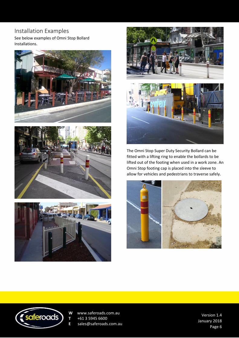
Installation Examples See below examples of Omni Stop Bollard
Installations.
The Omni Stop Super Duty Security Bollard can be
fitted with a lifting ring to enable the bollards to be
lifted out of the footing when used in a work zone. An
Omni Stop footing cap is placed into the sleeve to
allow for vehicles and pedestrians to traverse safely.

W www.saferoads.com.au T +61 3 5945 6600 E [email protected]
Version 1.4
January 2018
Page 7
Installation Drawing Item 1 – Reinforcement cage assembly including
Bollard Tube receiver
Item 2 – 5000PSI/32MPa concrete footing,
24in/600mm dia. X 71in/1800mm deep
Item 3 – 55in/1400mm long “Omni” pipe plus domed
cap, 6in/150mm nominal O.D.
W www.saferoads.com.au T +61 3 5945 6600 E [email protected]
Version 1.4
January 2018
Page 8
Installation Procedure Important note:
Saferoads OMNI-STOP Super Duty Security Bollard
has been crash tested and can stop a 5000lbs/2270kg
vehicle travelling at 30mph/50kph when surrounded
by 250mm thick concrete.
Saferoads OMNI-STOP Super Duty Security Bollard
has also been crash tested and can stop a
5000lbs/2270kg vehicle travelling at 30mph/50kph
when surrounded by SP – poorly graded sand.
However effective safe zone must be increased by a
factor of 2.5.
Installation outside of these conditions may be
possible, but a geotechnical engineer should be
engaged to recommend appropriate design.
Before commencing ensure that you have had all
services located and clearly identified using “Dial
Before You Dig” or “Before You Dig Call 811”. Ensure
you complete the Inspection and Test Plan (ITP).
Tools Required:
• Auger and or digging tools
• String line
• Spirit level
• Reo spacers
• 5000PSI/32MPa concrete
• Pencil vibrator
• 6in/150mm x 57in/1450mm light galvanised
pipe
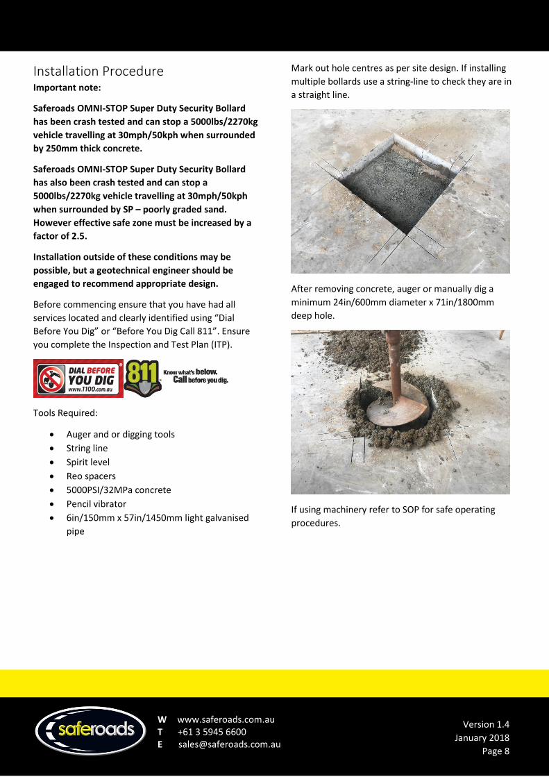
Mark out hole centres as per site design. If installing
multiple bollards use a string-line to check they are in
a straight line.
After removing concrete, auger or manually dig a
minimum 24in/600mm diameter x 71in/1800mm
deep hole.
If using machinery refer to SOP for safe operating
procedures.

W www.saferoads.com.au T +61 3 5945 6600 E [email protected]
Version 1.4
January 2018
Page 9
Place 4 reinforcement spacers under the cage to allow
the reinforcement cage to sit clear of the sub-soil.
Insert the Omni-Stop Super Duty Security Bollard
reinforcement cage, ensuring that the cage is at equal
distance from the edges of the hole. Also ensure the
top of the sleeve is level with the finished concrete
surface.
Use a spirit level to ensure that the reinforcement
cage assembly is correctly positioned.
Note: using a 6in/150mm x 57in/1450mm light
weight galvanised pipe placed into the cage to check
that the bollards will be vertical may assist.
Pour concrete into the space surrounding the reo cage
to approximately 12in/300mm and then re-check
levels. (Concrete must be 5000PSI/32MPa).
W www.saferoads.com.au T +61 3 5945 6600 E [email protected]
Version 1.4
January 2018
Page 10
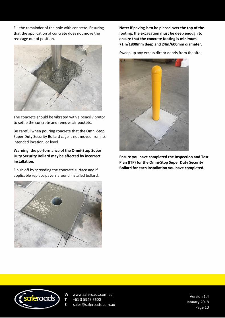
Fill the remainder of the hole with concrete. Ensuring
that the application of concrete does not move the
reo cage out of position.
The concrete should be vibrated with a pencil vibrator
to settle the concrete and remove air pockets.
Be careful when pouring concrete that the Omni-Stop
Super Duty Security Bollard cage is not moved from its
intended location, or level.
Warning: the performance of the Omni-Stop Super
Duty Security Bollard may be affected by incorrect
installation.
Finish off by screeding the concrete surface and if
applicable replace pavers around installed bollard.
Note: If paving is to be placed over the top of the
footing, the excavation must be deep enough to
ensure that the concrete footing is minimum
71in/1800mm deep and 24in/600mm diameter.
Sweep up any excess dirt or debris from the site.
Ensure you have completed the Inspection and Test
Plan (ITP) for the Omni-Stop Super Duty Security
Bollard for each installation you have completed.
W www.saferoads.com.au T +61 3 5945 6600 E [email protected]
Version 1.4
January 2018
Page 11
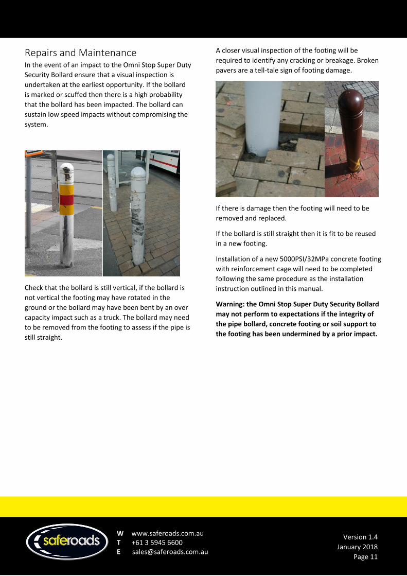
Repairs and Maintenance In the event of an impact to the Omni Stop Super Duty
Security Bollard ensure that a visual inspection is
undertaken at the earliest opportunity. If the bollard
is marked or scuffed then there is a high probability
that the bollard has been impacted. The bollard can
sustain low speed impacts without compromising the
system.
Check that the bollard is still vertical, if the bollard is
not vertical the footing may have rotated in the
ground or the bollard may have been bent by an over
capacity impact such as a truck. The bollard may need
to be removed from the footing to assess if the pipe is
still straight.
A closer visual inspection of the footing will be
required to identify any cracking or breakage. Broken
pavers are a tell-tale sign of footing damage.
If there is damage then the footing will need to be
removed and replaced.
If the bollard is still straight then it is fit to be reused
in a new footing.
Installation of a new 5000PSI/32MPa concrete footing
with reinforcement cage will need to be completed
following the same procedure as the installation
instruction outlined in this manual.
Warning: the Omni Stop Super Duty Security Bollard
may not perform to expectations if the integrity of
the pipe bollard, concrete footing or soil support to
the footing has been undermined by a prior impact.
W www.saferoads.com.au T +61 3 5945 6600 E [email protected]
Version 1.4
January 2018
Page 12
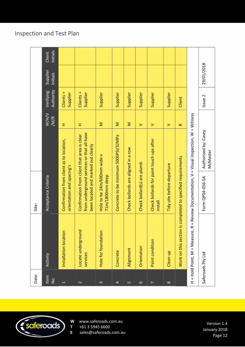
Inspection and Test Plan
Clie
nt
Init
ials
H =
Ho
ld P
oin
t, M
= M
easu
re, R
= R
evie
w D
ocu
men
tati
on
, V =
Vis
ual
Insp
ecti
on
, W =
Wit
nes
s
29
/01
/20
18
Sup
plie
r In
itia
ls
Ver
ifyi
ng
Au
tho
rity
Clie
nts
+
Sup
plie
r
Clie
nts
+
Sup
plie
r
Sup
plie
r
Sup
plie
r
Sup
plie
r
Sup
plie
r
Sup
plie
r
Sup
plie
r
Clie
nt
Issu
e 2
W/H
/V/M
/R
H
H
M
M
M
V
V
V
R
Au
tho
rize
d b
y: C
asey
M
cMas
ter
Acc
epta
nce
Cri
teri
a
Co
nfi
rmat
ion
fro
m c
lien
t as
to
loca
tio
n,
ori
enta
tio
n a
nd
sp
acin
g’s
Co
nfi
rmat
ion
fro
m c
lien
t th
at a
rea
is c
lear
fr
om
un
der
gro
un
d s
ervi
ces
or
that
all
hav
e b
een
loca
ted
an
d m
arke
d o
ut
clea
rly
Ho
le t
o b
e 2
4in
/60
0m
m w
ide
x 7
1in
/18
00
mm
dee
p
Co
ncr
ete
to
be
min
imu
m 5
00
0P
SI/3
2M
Pa
Ch
eck
bo
llard
s ar
e al
ign
ed in
a r
ow
Ch
eck
bo
llard
(s)
are
plu
mb
Ch
eck
bo
llard
s fo
r p
ain
t to
uch
up
s af
ter
inst
all
Tid
y si
te b
efo
re d
epar
ture
Wo
rk o
n t
his
sec
tio
n is
co
mp
lete
d t
o s
pec
ifie
d r
equ
irem
ents
Site
:
Form
QP
04
-05
6-S
A
Act
ivit
y
Inst
alla
tio
n lo
cati
on
Loca
te u
nd
ergr
ou
nd
se
rvic
es
Ho
le f
or
fou
nd
atio
n
Co
ncr
ete
Alig
nm
ent
Ori
enta
tio
n
Pai
nt
con
dit
ion
Cle
an u
p
Safe
road
s P
ty L
td
Dat
e:
Item
N
o.
1 2 3 4 5 6 7 8