
W L- TR- 93- 202 7 ll l - Defense Technical Information Center · f y'our address has changed, If...
50
AD'-A266 341 W L- TR- 93- 202 7 tlIIilitfliiI~l IhifIll ll l HIGH FLUX HEAT EXCHANGER EDWARD M. FLYNN MICHAEL J. MACKOWSKI MCDONNELL DOUGLAS MISSILE SYSTEMS P.O. BOX 516 ST. LOUIS, MO 63166 DTIC JAN 1993 tJN2 9199311 INTERIM REPORT Oct 90 - Oct 91 APPROVED FOR PUBLIC RELEASE; DISTRIBUTION IS UNLIMITED. AERO PROPULSION AND POWER DIRECTORATE WRIGHT LABORATORY AIR FORCE MATERIEL COMMAND WRIGHT PATTERSON AFB, OH 45433-7650 93-14823
Transcript of W L- TR- 93- 202 7 ll l - Defense Technical Information Center · f y'our address has changed, If...
AD'-A266 341W L- TR- 93- 202 7 tlIIilitfliiI~l IhifIll ll l
HIGH FLUX HEAT EXCHANGER
EDWARD M. FLYNNMICHAEL J. MACKOWSKI
MCDONNELL DOUGLAS MISSILE SYSTEMSP.O. BOX 516ST. LOUIS, MO 63166 DTICJAN 1993 tJN2 9199311
INTERIM REPORT Oct 90 - Oct 91
APPROVED FOR PUBLIC RELEASE; DISTRIBUTION IS UNLIMITED.
AERO PROPULSION AND POWER DIRECTORATEWRIGHT LABORATORYAIR FORCE MATERIEL COMMANDWRIGHT PATTERSON AFB, OH 45433-7650
93-14823

NOT I C I
Whcn (Government drawings, specIfictt irn-., er t. ;it, .ir' n:-ed 1-
.MV purpose other thc,, in connection with a def4 ittelv i.overument-re atCdprocurement, the United !States Government incurs TC- r,,ponTI;sbilitv or in':
ohIi ig:i ti on whatsoever. The fact that tho government mNv h!ave lormuinatod orin any way supplitd the said drawings, specifications, or other data, i no:tto he regarded bN implicititon, or otherwise in any manner construed, as,icinsing the holder, or an" other nerson or corporation; rr os convev.'-ng:mx rights or pern'i.S iOu to manufacture, use, or sell anv ;);Itented Irventionthat may in any way bu related thereto.
11;is report is releasable co the Natioal Technical Inforrmation ner'.c,N,1, IS ) . At NTTS, it wi I I bc availablc to the general pubi ! in
foreign nations.
This, technical report has be-,n r-viewed and is ap•roved tor pub•.-t ion.
it IIRY BEAM., B.L. .cF,IDDENSect'ion Chief Chief"I herma Technology Sect iot Power Technology Branch
• l( il. Il, Lt Col , !SA I.t) p-ut ' C h i (, f
AC I'•,0p Ace Pow" W( ) iv is ionA. I- Propl Is j on l, Pow r" 1) i rec ctorait c
f y'our address has changed, If vou wish to be reruoved from, our mailinp'ist, or if the addressee Is no longer employed hv your orgari7ation please
noti v WL/ Poios, WPAFB, OH 4%433- 7659 to help us maintain a currentmailing list.
Cnpik.ý of- this report should not htc returned unless return is required byscrt, tV ('consideraton-,s, contractual obl ig.it ions, or notice on a specificdocutmen t.
ii

Sform ApprovedREPORT DOCUfVIENTAT!ON PAGt OMB No •O104 o18
I AGENCY USE ONLY (Lteave bI,,A T2 NR AT T. DýF PORT TYPE AND DATES cOVERED I october 199(-|_____,_____________Tnter4_ _eport 29 October 199'
4, TITLE AND SUBTITLE 5. FUNDING NUMBERS
HIGH FLUX HEAr CFi 363F5-9Q-C-?054PE 62203_PR 3145
6. AUTHOR(S) TA 20WU Cl
Edward M. FlynnMichael J. Mackowski
7. PERFORMING ORGANIZATION N -,'( A,NU ADDRESS(CS,' 8. PERFORMING ORGANIZATIONREPORT NUMBER
McDonnell Dougias•.i•I •.•,,-C:'
P.O. Box 516St. Louis, MO 631Ec
9. SPONSORING MONITORfiG •kE1 ..*vS) ANO .' D0!-FSWW(ES 10. SPONSORING. MONITORING
Aero Propulsion in'd " ....- AGENCY REPORT NUMBER
Wright LaboratcryAir Force Materiel Cc,- : ar- WL-TR-93-2027Wright Patterson ; , ,.,WL/POOS, Attn: .J . ";•:. i3 -24V
11. SUPPLEMENTARY NOTES
12a. DISTRIBUTION AVAtLA5fL TY S T"• r. ,;f 12b DISTRIBUTION CODE
Approved for PurIl-c le- .*;-*'i•, '
unlimited.
113- ABSTRACT
This interim remrT docu.aotnts. the res-.lLs of the first two phases of a four-phaseprogram tc develep g high flux hsat exchanger for cooling future high performanceaircraft electronics. Pha:v, -1 defines future needs for high flux heat removal inadvanced military electronics systems. The results are sorted by broad applicationcategories, which are: I) commercial digital systems, 2) military data processors, 3)power processorm, end 4) radar and optical systems. For applications expected to befielded in five to ton y-rar, the outlook is for steady state flux levels of 30-50 W/cm 2
for digital prock86on- and siwvenal bdred Wicm 2 for power control applications. InPhase II, s trade &.,,udy was coniucted on emerging cooling technologies which couldremove a ,teady ebat9 :;lp beat flux of 100 W/ar 2 while holding chip junctiontemperature to 90 'C. Constraints imposed on heat exchanger design, in order toreflect operation in a fighter a•icraft environment, included a practical lower limit oncoolant supply tem.nperature, the preference for a nontoxic, nonflammable, andnonfreezing coolant, the neex to Laniniize weight and volume, and operation in anaccelerating environment. T'he trade study recommended the Compact High IntensityCooler (CHIC) for desigr, fabrication, and toat in the final two phases of this program.
14ý SUBJECT TERMS IS. NUMBER OF PAGES
Electronic CoolFi-g, Ril Pew-.' ,lctronics 4816 PRICE CODE
Il. SW(IJRITY 6I7AS•-(PAnGN 1' SiCriRITY 4 IA',SffICATION 19 SECURITY CLASSIFICATION 20. LIMITATION OF ABSTRACTOF REPORTI OF Tffl' VA44 OF ABSTRACT
U J UL
Starndard Form 298 (Rpv " 99)
t" A %%! It 2i

FOREWORD
This report presents results developed by McDonnell Douglas Missile SystemsCompany (MDMSC) under Air Force Contract F33615-90-C-2054 "High Flux HeatExchanger." This development program was conducted under sponsorship of the AirForce Wright Laboratory, with Dr. Jerry E. Beam and Mr. Angel S. Reyes, POOS, asProject Managers. The program is divided into four phases:
1. Cooling Requirements for Future Avionics
2. Cooling Concept Trade Study
3. Cooling Concept Detailed Design
4. Fabrication, Test, and Data Analysis
This interim report documents the results of the first two phases.
This program was managed at MDMSC by Mr. Michael J. Mackowski and Mr.Brian K. Bennett. Mr. Mackowski also performed the technical effort in Phase I. ThePrincipal Investigator was Mr. Edward M. Flynn.
Contributions of data from the following sources are acknowledged: AlliedSignal; Convex Computers; Coriolis Corp; Cudo Technologies; Frisby AirborneHydraulics, Inc.; General Dynamics; Honeywell; Hughes Aircraft; J. S. DeWeese Co.;Lawrence Livermore Laboratory; Lockhart; Marlow Industries, Inc.; Microelectronicsand Computer Technology Corp.; Motorola; Purdue University; Sundstrand Aerospace;Texas Instruments; Thermacore, Inc.; 3-M; Triangle Research and Development Corp.;and Westinghouse.
iii
TABLE OF CONTENTS
Section Pv
F O R E W O R D ...............................................................................................
1. IN TRO D U CTIO N ....................................................................................... 1
1.1 Background ................................................................................ 11.2 O bjective .................................................................................... 11.3 Sum m ary .................................................................................... 2
1.3.1 Future Requirements Study ........................................ 21.3.2 Cooling Concept Trade Study ...................................... 2
2. FUTURE REQUIREMENTS STUDY .................................................. 3
2.1 Commercial Digital Systems ..................................................... 32.1.1 Processors ..................................................................... 32.1.2 Mainframe Computers ................................................. 5
2.2 Military Data Processors .......................................................... 52.2.1 G eneral ......................................................................... 52.2.2 Aircraft Applications .................................................. 72.2.3 Missiles and Smart Weapons ..................................... 82.2.4 Summary - Data Processors ....................................... 8
2.3 Power Processors ...................................................................... 92.3.1 G eneral ......................................................................... 92.3.2 Low Voltage Power Supplies ....................................... 92.3.3 High Power Systems ................................................... 92.3.4 Neutral Particle Beam ................................................. 92.3.5 Summary - Power Processors ..................................... 10
2.4 Radar and Optical Systems ....................................................... 102.4.1 Conventional Radar ..................................................... 102.4.2 Solid State RF Arrays.................................................. 102.4.3 Laser Radar ................................................................ 112.4.4 Optical Sensors ........................................................... 112.4.5 Laser Communications ................................................ 112.4.6 Summary - Radar and Optical Systems .................... 11
2.5 Conclusions - Future Cooling Requirements ........................... 11
3. COOLING CONCEPT TRADE STUDY ................................................ 13
3.1 Approach .................................................................................... 133.1.1 Evaluation Criteria ..................................................... 13
3.2 Requirements and Constraints ................................................ 133.2.1 Coolant Selection ......................................................... 143.2.2 Thermal Requirements ................................................ 153.2.3 Geometric Configuration ............................................. 153.2.4 Thermal Resistances ................................................... 153.2.5 Coolant Supply Temperature ..................................... 16
3.3 Cooling Concepts ....................................................................... 163.3.1 Compact High Intensity Cooler (CHIC) ..................... 163.3.2 Curved Channel Flow with Subcooled Boiling ........... 193.3.3 Evaporative Spray Cooler ............................................ 21
v

TABLE OF CONTENTS (Continued)
3.3.4 Heat Pipe...................................................... 223.3.5 Jet Impingement with Subcooled Boiling................. 243.3.6 Mficrochannel. Cooler......................................... 263.3.7 Pumped Capillary Evaporator ............................. 273.3.8 Other Concepts............................................... 28
3.4 Concept Comparisons.................................................. 283.4.1 System Weight Impact ...................................... 303.4.2 Life Cycle Cost................................................ 333.4.3 Safety and Reliability........................................ 343.4.4 Development Status and Risk .............................. 353.4.5 Thickness and Lateral Requirements ..................... 363.4.6 Other F-.ctors ............ .......... 36
3.5 Conclusions - Overall Comparisons.................................. 37
4. REF'ERENCES .................................................................. 38
Ai

LIST OF FIGURES
1. Motorola MM16M5ECL custom MCM ................................................ 6
2. 1750A single board computer ............................................................... 6
3. Definition of Thermal Resistance ......................................................... 16
4. Air Force PAVE PACE Liquid Flow-Through Board ........................... 17
5. CHIC Elements and Fluid Flowpaths ................................................... 17
6. Curved Channel Flow with Subcooled Boiling ...................................... 20
7. Evaporative Spray Cooling .................................................................. 21
8. Exploded View of Heat Pipe Heat Spreader ......................................... 23
9. Jet Impingement With Subcooled Boiling ............................................ 24
10. M icrochannel Cooler .............................................................................. 26
11. Actively Pumped Capillary Evaporator (Exploded View) ................... 28
12. Sensitivity of Aircraft Take-Off Gross Weight to Coolant SupplyTem perature .......................................................................................... 31
13. Sensitivity of Aircraft Take-Off Gross Weight to Coolant Flowrate ....... 31
14. Sensitivity of Aircraft Take-Off Gross Weight to HFHE PressureD rop ...................................................................................................... 32
15. Sensitivity of Aircraft Take-Off Gross Weight to HFHE Structuraland 'ontained Coolant Weight ............................................................ 32
vii

LIST OF TABLES
Table No,.ag
1. Summary of Future Electronics High Flux Cooling Requirements ......... 4
2. Trade Study Evaluation Criteria .......................................................... 14
3. Predicted Design Points and Performance ............................................ 19
4. Trade Study Scoring Results ................................................................ 29
5. Life Cycle Cost Assessments ................................................................ 33
6. Reliability Assessm ent ........................................................................... 34
7. Development Status Evaluation ............................................................ 36
viii
SECTION 1
INTRODUCTION
1.1 Background
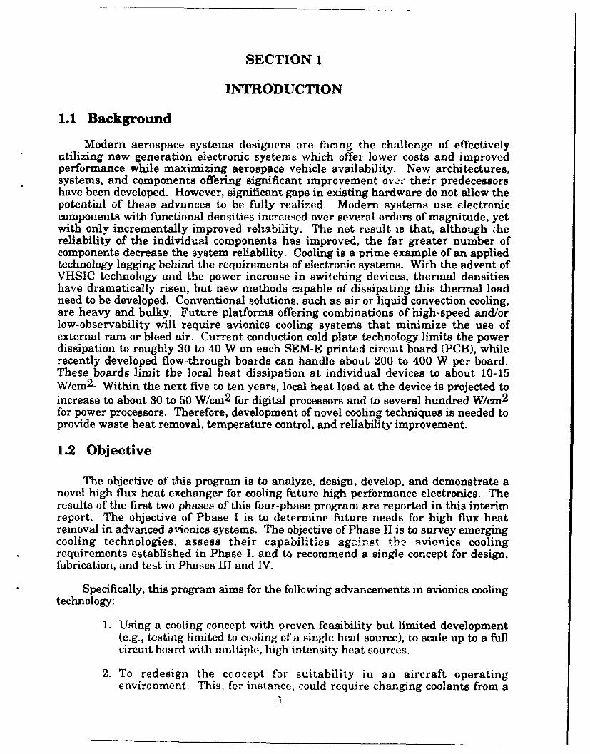
Modern aerospace systems designers are facing the challenge of effectivelyutilizing new generation electronic systems which offer lower costs and improvedperformance while maximizing aerospace vehicle availability. New architectures,systems, and components offering significant improvement over their predecessorshave been developed. However, significant gaps in existing hardware do not allow thepotential of these advances to be fully realized. Modern systems use electroniccomponents with functional densities increased over several orders of magnitude, yetwith only incrementally improved reliability. The net result is that, although khereliability of the individual components has improved, the far greater number ofcomponents decrease the system reliability. Cooling is a prime example of an appliedtechnology lagging behind the requirements of electronic systems. With the advent ofVHSIC technology and the power increase in switching devices, thermal densitieshave dramatically risen, but new methods capable of dissipating this thermal loadneed to be developed. Conventional solutions, such as air or liquid convection cooling,are heavy and bulky. Future platforms offering combinations of high-speed and/orlow-observability will require avionics cooling systems that minimize the use ofexternal ram or bleed air. Current conduction cold plate technology limits the powerdissipation to roughly 30 to 40 W on each SEM-E printed circuit board (PCB), whilerecently developed flow-through boards can handle about 200 to 400 W per board.These boards limit the local heat dissipation at individual devices to about 10-15W/cm 2 . Within the next five to ten years, local heat load at the device is projected toincrease to about 30 to 50 W/cm 2 for digital processors and to several hundred W/cm 2
for power processors. Therefore, development of novel cooling techniques is needed toprovide waste heat removal, temperature control, and reliability improvement.
1.2 Objective
The objective of this program is to analyze, design, develop, and demonstrate anovel high flux heat exchanger for cooling future high performance electronics. Theresults of the first two phases of this four-phase program are reported in this interimreport. The objective of Phase I is to determine future needs for high flux heatremoval in advanced avionics systems. The objective of Phase II is to survey emergingcooling technologies, assess their capabilities against tbi' qvionics coolingrequirements established in Phase I, and to recommend a single concept for design,fabrication, and test in Phases III and TV.
Specifically, this program aims for the following advancements in avionics coolingtechnology:
1. Using a cooling concept with proven feasibility but limited development(e.g., testing limited to cooling of a single heat source), to scale up to a fullcircuit board with multiple, high intensity heat sources.
2. To redesign the concept for suitability in an aircraft operatingenvironment. This, for instance, could require changing coolants from a
1

2. To redesign the concept for suitability in an aircraft operatingenvironment. This, for instance, could require changing coolants from athermally desirable coolant such as water to a thermally poorer butbetter-suited colanIt for aircraft such as puivy ,lpha olefin i i)
3. To demonstrate hef't removal carhbilit•es for aircraft avionif.-: . , ,tlvgreater than those obtainable with, currTentlv used heat exchangf rs.
4. To demonstrate high heat, flux capability and high packa-Ing de•: it Ito not rely on extensive fin area for heat ,er oval.
1.3 Summary1.3.1 Future Reauiremeuj ~j~js.�_�- An industry survey was perfo,,, lo
determine future needs for high f!'x heat removR, in advanced electronics systems.The focus was cooling technology development requirements for military anvo',m''•systems. Commercial electronics suppliers were included because many high po.verdevices are being developed in that part of the industry. The results are sorted bybroad application categories, which are: 1) commercial digital systems, 2) military,lata processors, 3) po-ver proce•snr,-r, and 4) radar and optical syvtený. F'orapplications expected to be fi,vided in five to ten years, the outlook is for stenivy-tatoflux levels of 30-50 W/cm 2 for digital processors and sevc ral hundred W/cm 2 for pove'rcontrol applications iisiu.- adva-,ced MOSFFI's ,%r MOS-conTtrolled thl'vro-t•'rtechnology.
1.3.2 Cooling Concept Trade Study - Evaluations were made of emerging coolingtechnologies which could remove a steady state chip heat flux of 100 W/cm 2 whileholding chip junction temperature to 90 'C. Several constraints were imposed on thecooler due to the intended application of cooling fighter aircraft electronics.Constraints included a practical lower limit on coolant supply temperature, thepreference for a nontoxic, nonflammable, and nonfreezing coolant, the need tominimize weight and voiume, and operation in an accelerating environment.Evaluation factors included aircraft system impact, cooler development status, andqualitative assessments of life cycle cost, reliability, maintainability, and safety.Seven concepts were identified which could meet the cooling requirements, and wereinvestigated in detail in order to make assessments againhL the evaluation fac'ors.The Compact High Intensity Cooler (CHIC) was selected for design, fabrication. •,dtVst in Phases 3 and 4 of this program.
2

SECTION 2
FUTURE REQUIREMENTS STUDY
A survcy i electronics industry and military avionics component suppliers andsystem dev-upers was performed to determine future requirements for high fluxthermal control technology. Existing military avionics systems primarily use passivecooling techniques for thermal management. Future systems are expected to havehigher power dissipation requirements, and the technology to handle higher heatloads needs to be developed. There are already several efforts underway, such as theAir Force Advanced Aircraft Avionics Packaging Technology (AAAPT) program, toaccommodate the thermal problems generated by large numbers of small heat loads(each less than about ten watts). But there is little work in progress to handleelectronic components that generate high localized heat fluxes on the order of 100W/cm 2 or more. This led the Wright Laboratory Aero Propulsion and PowerDirectorate to initiate this effort to develop new concepts in high flux heat exchangers.
This section summarizes the requirements analysis portion of that program. Itis not intended to be a systematic survey of all electronic thermal management needs,but rather a search to identify applications that have very high localized fluxproblems. Complicating this issue are the demands of military avionics systems,which have severe operating environments plus a renewed emphasis on reliability,ease of maintenance, and low cost. Therefore, the operational and packaging aspectsof the high flux devices were also investigated.
The survey process consisted primarily of phone interviews with devicemanufacturers and users. Technical papers, books, and product data sheets were alsoreviewed. The results are sorted by broad application category, as follows: 1)commercial digital systems, 2) military data processors, 3) power processors, and 4)radar and optical systems. A summary is presented in Table 1.
2.1 Commercial Digital Systems
2.1.1 P ,ofasrL- Some thermal management researchers anticipate that as digitalprocessors increase in speed and throughput, but decrease in size, the powerdissipated in these devices will rise to the order of 100 W per device. As the size ofthese chips is on the order of 1 cm on a side, the resulting flux density of 100 W/cm 2
presents a challenging thermal problem [1]. However, few existing devices dissipatemore than 20 W to 30 W, and the suppliers contacted could not predict with confidencethat flux levels would ever reach the 100 W level.
The largest heat loads in digital data processing devices are from centralprocessor units (CPUs) and gate arrays, which are customizable processors. Anexample of a state-of-the-art, high-performance gate array is the Mitsubishi M6008Xwhich has 400,000 working gates [2]. This device is designed to operate with amaximum heat dissipation of 22 W. A high performance CPU, such as the IntergraphC411, uses 1.0-micron CMOS and runs at 50 MHz, yet consumes only 3.5 W. TheMIPS R3000, a 32-bit CPU, operates at over 30 MHz, and is also in the 4 W range [3].The MIPS R4000, an advanced 64-bit processor, is not expected to use significantlymore power.
3
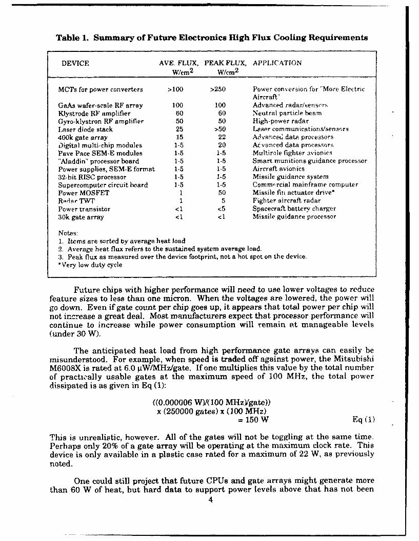
Table 1. Summary of Future Electronics High Flux Cooling Requirements
DEVICE AVE. FLUX, PEAK FLUX, APPLICATIONW/cm2 W/cm 2
MCTs for power converters >100 >250 Power conversion for "More ElectricAircraft"
GaAs wafer-scale RF array 100 100 Advanced radar/senscrsKlystrode RF amplifier 60 60 Neutral particle beamGyro-klystron RF amplifier 50 50 High-power radarLaser diode stack 25 >50 Laser communicationt/sens.rs400k gate array 15 22 Adivancetd data processorsDigital multi-chip modules 1-5 20 Aevvnced data processorsPave Pace SEM-E modules 1-5 1-5 Multirele fighter Avionics"Aladdin" processor board 1-5 1-5 Smart munitions guidance processorPower supplies, SEM-E format 1-5 1-5 Aircraft avionics32-bit RISC processor 1-5 1-5 Missile guidance systemSupercomputer circuit board 1-5 1-5 Commf'rcial mainframe computerPower MOSFET 1 50 Missile fin actuator drive*Rptiar TWT 1 5 Fighter aircraft radarPower transistor <1 <5 Spacecraft battery charger30k gate array <1 <1 Missile guidance processor
Notes:1. Items are sorted by average heat load2. Average heat flux refers to the sustained system average load.3. Peak flux as measured over the device footprint, not a hot spot on the device.*Very low duty cycle
Future chips with higher performance will need to use lower voltages to reducefeature sizes to less than one micron. When the voltages are lowered, the power willgo down. Even if gate count per chip goes up, it appears that total power per chip willnot increase a great deal. Most manufacturers expect that processor performance willcontinue to increase while power consumption will remain at manageable levels(under 30 W).
The anticipated heat load from high performance gate arrays can easily bemisunderstood. For example, when speed is traded off against power, the MitsubishiM6008X is rated at 6.0 gW/MHz/gate. If one multiplies this value by the total numberof practically usable gates at the maximum speed of 100 MHz, the total powerdissipated is as given in Eq (1):
((0.000006 W)/(100 MHz)/gate))x (250000 gates) x (100 MHz)
=150 W Eq (1)
This is unrealistic, however. All of the gates will not be toggling at the same time.Perhaps only 20% of a gate array will be operating at the maximum clock rate. Thisdevice is only available in a plastic case rated for a maximum of 22 W, as previouslynoted.
One could still project that future CPUs and gate arrays might generate morethan 60 W of heat, but hard data to support power levels above that has not been
4
found. Because gate arrays are slower and require more power and real estate thancustom chips, they are not likely to be used in compact military avionics.
2.1.2 Mainframe CoMputers - Although the Cray-2 and Cray-3 supercomputers areactively cooled via total liquid immersion [4], the trend is toward more passiveapproaches. The Cray machines dissipate hundreds of kilowatts in a five by three footenclosure which requires liquid cooling. In most supercomputers, the heat generatedby 2ach individual chip is actually low, but the total thermal load is high because alarge number of chips is used in a very compact arrangement. Most futuresupercomputers will use lower-powered chips, but special high-performance systemsmay have speed and packaging requirements which will generate heat loads highenough to demand active cooling.
Supercomputers manufactured by Convex Computers have the unique featureof being cooled without liquids, rel)ying completely on forced air. They canaccommodate 500 W per 18- by 36- inch board in this fashion. Using low-poweredGaAs chips, the typical heat generated per chip is 30 W, and they are spaced farenough apart to minimize the average heat load.
Multi-chip modules (MCMs) are becoming commonly used in commercial digitalprocessing applications, and are slowly making their way into military electronics.MCMs have several chips mounted on a common substrate, typically a few inchessquare. The chips are connected via microwires and/or traces laid into the substrate.This achieves much faster communicating speeds among the chips, improving overallprocessing speed significantly.
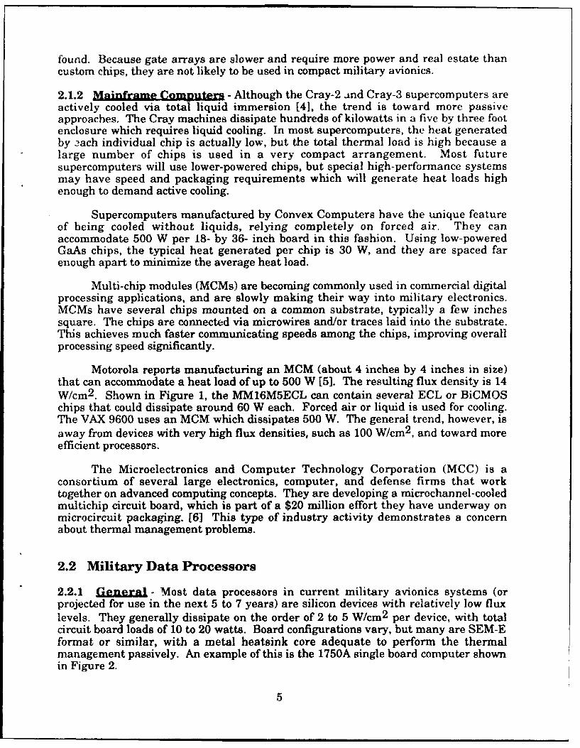
Motorola reports manufacturing an MCM (about 4 inches by 4 inches in size)that can accommodate a heat load of up to 500 W [5]. The resulting flux density is 14W/cm 2 . Shown in Figure 1, the MM16M5ECL can contain several ECL or BiCMOSchips that could dissipate around 60 W each. Forced air or liquid is used for cooling.The VAX 9600 uses an MCM which dissipates 500 W. The general trend, however, isaway from devices with very high flux densities, such as 100 W/cm 2 , and toward moreefficient processors.
The Microelectronics and Computer Technology Corporation (MCC) is aconsortium of several large electronics, computer, and defense firms that worktogether on advanced computing concepts. They are developing a microchannel-cooledmultichip circuit board, which is part of a $20 million effort they have underway onmicrocircuit packaging. [6] This type of industry activity demonstrates a concernabout thermal management problems.
2.2 Military Data Processors
2.2.1 Gene l - Most data processors in current military avionics systems (orprojected for use in the next 5 to 7 years) are silicon devices with relatively low fluxlevels. They generally dissipate on the order of 2 to 5 W/cm 2 per device, with totalcircuit board loads of 10 to 20 watts. Board configurations vary, but many are SEM-Eformat or similar, with a metal heatsink core adequate to perform the thermalmanagement passively. An example of this is the 1750A single board computer shownin Figure 2.
5
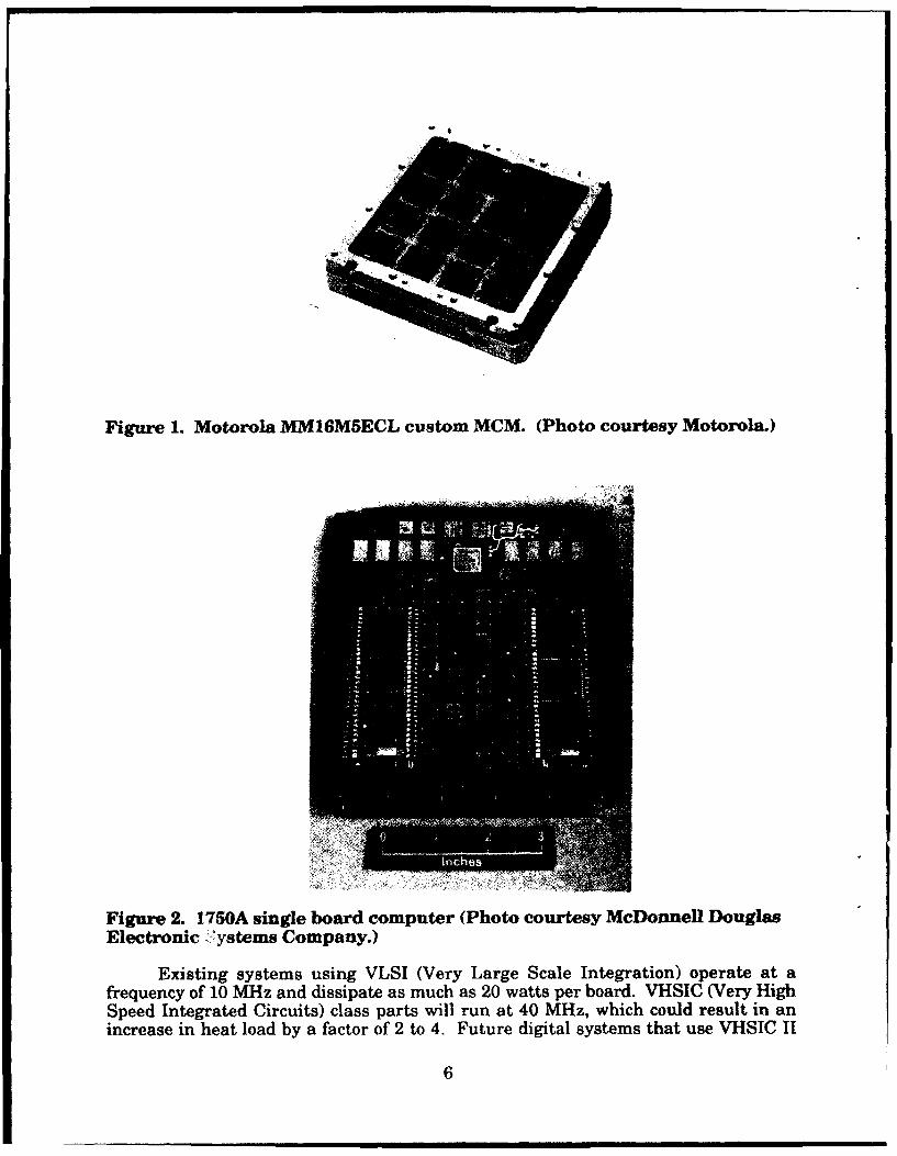
Figure 1. Motorola MM16M5ECL custom MCM. (Photo courtesy Motorola.)
Figure 2. 1750A single board computer (Photo courtesy McDonnell DouglasElectronic "ystems Company.)
Existing systems using VLSI (Very Large Scale Integration) operate at afrequency of 1.0 MHz and dissipate as much as 20 watts per board. VHSIC (Very HighSpeed Integrated Circuits) class parts will run at 40 MHz, which could result in anincrease in heat load by a factor of 2 to 4. Future digital systems that use VHSIC II
6

products are projected to push t.he heat load up by another factor of 2 to 4, putting theupper end at (20 W x 4 x 4) = 320 watts.
Gallium arsenide (GaAs) chips are beginning to replace silicon because of theirhigher speed and lower power. But GaAs is a poor thermal conductor, which makesheat spreading difficult within the chip, as the heat is generated at very tiny locationson the chip. CMOS (silicon) chips are ve'y low power, and are not quite as fast asGaAs. But the lower cost of CMOS devices, coupled with their low powerrequirements, makes them more popular than GaAs at this time. The Motorola 68040CPU is a CMOS chip that has over one million devices, yet consumes only one watt ofpower. BiCMOS is a compromise technology that provides increased speed at theexpense of somewhat higher power, but the power increase is only fractional. ECL(emitter coupled logic) is the fastest silicon-based technology, using bipolar ratherthan MOS switches. Large ECL arrays (multipurpose silicon chips often used formemory or custom processors) can have several million devices per chip, yet requireonly about 5 watts. Extremely large ECL arrays have been proposed that might reachthe 80 to 100 W/cm 2 level, but their use on military systems is many years into thefuture, and several avionics designers interviewed on this topic had difficultyimagining how such devices might be used. Large GaAs processors may alsoeventually reach that flux level, but it will be ten years or so before those systems aredeveloped, according to most sources. 32-bit RISC processors (at least some of whichare GaAs) ar- being used now in a few missile data processors, and these require onlya few watts each.
Many military avionics systems presently in development use general purposeoff-the-shelf processors. Actual operational systems will likely use custom chips,which will result in a lower total chip count (because the custom chips package theirfunctions more efficiently and can operate faster) which will also ease packagingconstraints. Additionally, many missiles and other weapons have such uniquerequirements that general purpose chips will not perform adequately. Custom chipswill be required, and these can be tailored for higher speed and lower power thanthose used in development and prototyping programs. Higher density chips are alsonow being designed to operate at lower voltage levels, resulting in lower overall powerrequirements.
2.2.2 Aircraft AalHcations - The Air Force Pave Pace program is intended toidentify, and then develop, the standard modular avionics which will be needed forfuture aircraft, specifically focussing on the MultiRole Fighter (MRF). Pave Pace is an18-month program that began in March of 1990 with three prime contractors. Itinvolves a wide-ranging technology assessment and has goals of reduced cost andgreatly improved reliability.
The portion of the Pave Pace study performed by the McDonnell AircraftCompany considered the architectural requirements for future avionics systems, andthey have developed a building block concept for future avionics suite designs. Thisresulted in a functional breakdown into about 200 SEM-E level line-replaceablemodules (LRMs) which would be needed for the entire MRF avionics suite. Many ofthe units have heat dissipation of less than 40 W, which is the JIAWG (JointIntegrated Avionics Working Group) standard allowable upper limit for SEM-Eboards. In general, the localized heat flux is low, and can be handled by existingpassive approaches. However, about half of the LRMs would dissipate over 40 W, andtherefore would require some sort of liquid cooling. The units with a need for high
7

total heat load cooling (in this particular study) are primarily the integrated coreprocessors. [7]
To support the Pave Pace program, the USAF began a complimentary program,called Advanced Aircraft Avionics Packaging Technology (AAAPT), to consider how topackage these LRMs. There were three contracts awarded, including one toAT&T/Bell Labs to develop active cooling technology for the LRMs. This programdeveloped a liquid flow-through heat exchanger with dripless quick-disconnects thatwould meet the JIAWG standards for form, fit, and function. These were built andtested at 200 W per board dissipation while holding a junction temperature at 8O°C. Alow-cost stamped aluminum heat exchanger was imbedded in the board, and it passedlife, vibration, and environmental tests [8]. There are now plans to build and test adouble-width (two-slot) LRM version having multi-chip modules for a 400 W total heatload.
2.2.3 Missiles and Smart Weapons - A far-term application which is currently inthe early study phase is automatic target recognition (ATR). Such an application willrequire massive computing power to be packaged into missiles and small munitions.If higher data processing throughput is available, the software is much easier to write,thus reducing cost. This will cause an ever-increasing need for greater throughputcapability. This is an area which may eventually drive the processing and packagingrequirements together such that novel thermal management techniques will berequired, but the numbers are difficult to quantify at this time.
To achieve one billion bits-per-second processing throughput capability in apackage suitable for advanced missiles and smart munitions, DARPA began theAladdin program. This processing capability will be required for ATR and similarmissions. The two prime contractors are Honeywell and Texas Instruments. By using32-bit RISC processors, which dissipate 2 to 3 watts per chip, and MCMs, overall heatloads remain manageable at about 65 W for the total 6-inch long by 4-inch diameterpackage.
Guidance electronics for SDI missions, where processing for imaging/datacollecting/targeting is more intense, might use several MCMs to achieve the requiredspeed and throughput. For a conceptual study done for an SDI application, heatdissipation was estimated to be about 10 to 15 W per chip, but over a hundred suchchips were needed, suggesting a need for a liquid cooling approach. Flux levels of 100W/cm 2 were deemed unlikely in that application. Even a systems such as BrilliantPebbles, which has been touted as having tremendous computational capabilities, maynot require more than 100 W per board.
2.2.4 Smmar. - Data Processors - The intense interest in thermal managementof digital systems, evidenced by the many technical papers and research beingperformed in this area, appears to be driven by high total board loads, not localizeddevice loads. Designers of military avionics predict that the total power per SEM-Etype board may go as high as 200 - 400 W for digital systems. But localized heat fluxis likely to be relatively low, not much more thaa 30 to 50 W/cm 2 for most devices.While no chip manufacturer or avionics supplier was willing to predict that 100 Wdata processing chips will be common in future military avionics systems, it is possiblethat such a cooling requirement may eventually be needed for very specialized high-performance digital applications.
8

2.3 Power Processors
2.3.1 Gene~l - Requirements for inverters and motor controller drives wereresearched by talking to users and system developers, including NASA, GeneralDynamics, Douglas, Allied-Signal, Westinghouse, and others. Data sheets were alsoreviewed for high power MOSFETS and Insulated Gate Bipolar Transistors (IGBTs)from several suppliers.
For advanced power supplies using high power solid state devices (SCRs, MCTs,transistors, etc.), the switching devices may be characterized as single-point heatsources with cperating temperature controlled by a conductive heat sink. Individualdevice peak temperature remains the limiting factor in determining operatingcharacteristics. Whatever the cooling method, the thermal resistance of the heattransport system must be small enough to prevent hot spots from occurring at thedevice-to-cooling-medium interface. Due to operational requirements and limitations,each of these devices must be electrically isolated from each other, furthercomplicating the heat collection process when multiple devices are use, wLich isalmost always the case.
2.3.2 Low Voltage Powe Su=He - A low-voltage, passively-cooled power supplyhas been developed for a Pave Pace type (SEM-E format) implementation. Thistransforms the 270 VDC to lower voltages (±5, +15 VDC, etc.) for distribution toindividual circuit boards. Alternatively, smaller converters on each board can convertan intermediate 50 V bus level to the lower voltages used by digital and small signalcircuits. A 200 W power supply (waste heat of about 40 W at a 40 ampere output) hasbeen developed for the ATF program. A larger unit, processing over one kilowatt atvery high efficiencies, is under development by Texas Instruments. This boardtypically dissipates about 50 W, and requires liquid cooling.
2.3.3 High ower . stema - Power processing for electromechanical actuators forthe More Electric Aircraft initiative will involve high current and high voltages. Theuse of solid state switching devices, with typical voltage drops of one to two volts, will,in some instances, result in power dissipation of several hundred watts per device.The actuators involved will require 30-40 hp (22 - 30 kilowatts) motors. The powersupplies to drive them are generally assumed to use advanced solid state switchingdevices such as MOS-controlled thyristors (MCTs), which can handle the high currentat reasonably high switching speeds. These devices may reach current densities of150 A/cm 2 or higher, resulting in hundreds of watts of cooling requirement (9]. Theoverall packaging approach to handle the combination of high voltage, high current,and high heat flux is still being developed.
2.3.4 Neutral Particle Beam - RF output transistors used in a space-based RFamplifier with a 400 kW RF output results in 3 kW waste heat, and must be packagedin a system about the size of a bread box. In the continuous operating mode, thesetransmitters generate a heat flux of about 60 W/cm 2 . Being a space application,packaging constraints will probably be specialized. A cryogenic liquid microchannelcooler may be required, but this would be a very unusual case with limited relevanceto other applications in this survey.
9

2.3.5 Summary_ - Power ProcessorR - Solid state power switching devices willcertainly generate higher heat loads than digital devices. MCTs operate at currentdensities of 150 to 200 Acn12 over an active die area of less than I cm 2 , resulting in aheet flux of over 400 W/cm 2 . Although generally operated in a low duty cycle pulsedmode for inverters and motor controllers, the steady-state heat levels for these deviceswill still be in the 100 Wi/cm 2 range. If operated in a continuous mode aw 1 t•wercontrol switch, for example, a single MCT would generate a continuous heat load of200 W or more.
In summary, a cooling capability of at least 100 W/cm 2 for power applications isneeded. It could even be higher, depeniding on the application. Unfortunately, for thepurposes of this study, the most demanding applications are the ones which ar týemost poorly defined (because they are usually only concepts rather than existirfmgdesigns), resulting in an uncertain requirements projection.
2.4 Radar and Optical Systems
2.4.4 Conventional RaLar - Existing radar systems are discretely packaged,usually split into an antenna unit, a modulator/exciter (signal generator), a powerarniplifier for the transmitter, a receiver unit, and a signal processor to sort out theretu.'rs, Because the traveling wvaves tubes (TWTs) can have waste heat levels in thehundreds of watts, they are sometimes directly immersed in an inert fluid. Theamplifiers and processors have a much lower heat dissipation, and are cooled viaforced air or by mounting the units on coldplates. Despite the high total heat loads,the localized heat flux is generally low, as evidenced by the low ratings of radarsystems coldplates, typically 1 to 2 W/cm 2 . Because of concerns with leakage andreliability of liquid cooling systems, radar developers are trying to make the poweramplifiers more efficient so that conduction or forced-air cooling is all that is needed.Fiature systems are expected to combine radar subsystems into very compact, highdensity assemblies (wafer-scale and microwave monolithic integrated circuit.F,MMICs), or to divide them into more general functional units which are implementedon standardized LRMs.
2.4.2 olid State RF Arrays - Newer approaches, such as active arr'ys based onwafer-scale technology, will require very compact heat exchangers to be built directlyinto the assembly. In these devices, all of the functions are built into a singlemonolithic structure. This combines the antenna, the transmit/receive (TMR) modules,and the data processor. The resulting concentrated heat load requires that a liquidcooling manifold be built as an integral part of the assembly. The overall packagingdensity is limited by the half-wavelength spacing required between the RF ele-nents,This larger area required by the antenna portion then provides greater room in thepackage for the digital section, thus easing thermal management. As part of theAAAPT program, Westinghouse Electronic Systems Group studied this RF packagingproblem.
The cooling need is generated by the R/F elements, the solid state poweramplifiers, and the signal processors that analyze the return signal. Another concernis that any significant amount of heat generated can cause physical distortion of theantenna elements, which can distort the beam. The trend now is toward higher powerand multiple, narrow beams.
10

Fortunately, the MMIC devices used can operate reliably at somewhat elevatedtemperatures (over 1001C), thus easing the thermal control problem somewhat. Whilea MMIC power amplifier may dissipate at certain locations over 2 kW/cm 2 , this occursover a very small area, and can spread to less than 10 W/cm 2 at the heat exchangerinterface. These arrays could include thousands of transmit/receive elements,generating total heat loads in the kilowatts. [10]
2.4.3 Laser Radar - Advanced terminal guidance systems for missiles and smartmunitions will need to acquire and select targets by matching them with imagesdigitally stored in the missile's guidance system. One way such target recognition canbe implemented is with laser radar sensors, which can generate high resolutionimaging data and send it to a processor for matching. The data processors for thisapplication will require special cooling considerations, as will the laser diode sourcesfor the optical radar sensors. Current studies indicate that the data processor for sucha system will require only 50 W per board, which can be approximately SEM-E in size.
2.4.4 0otical Sesors - The U.S. Army Mast Mounted Sight is used on the OH-58Dhelicopter to peer over the battlefield without completely exposing the helicopter. Aprocessor is used to stabilize the sensor platform (visual TV/IR), perform tracking andtargeting functions, and link it the to the weapons systems. A study conducted by theMcDonnell Douglas Electronics Systems Company (MDESC) to upgrade this processorto SMT (surface mount technology) GaAs technology resulted in a 40 W per board (twoboards total) cooling requirement, which can be met by passive techniques.
2.4.5 Las.r Commnnicatiom - Laser diodes used for communications and sensorshave high localized flux levels, typically about 25 W/cm 2 [11i. The total area isusually quite small however, and there are seldom many other large heat generatingcomponents mounted nearby. Additionally, the packaging and cooling approaches areoften rather unique, with only limited relevance to other applications.
2.4.6 Summary- Radar and Ontical Systems - The most likely drivers for highflux cooling needs in this area will come from active RF arrays and laser devices. Bothuse new technology that generates very high localized heat loads, and both topics arealready the subject of significant research efforts in order to solve their thermalmanagement problems.
2.5 Conclusions - Future Cooling Requirements
Thermal loads for military avionics systems will continue to increase. Powercontrol applications will create the most challenging problems for high flux thermalmanagement systems, while certain high-performance digital systems are expected tohave a lesser but still significant need for high flux coolers.
High heat load requirements may be divided into two categories:
1. Systems with many sources of relatively low heat flux (5-20 W each)2. Systems with very high localized heat flux (>100 W/cm 2 )
If only the first case applies to a particular problem being studied, then there is acertain set of thermal management solutions available using existing technology. Ifthe second category also applies, then existing thermal management approaches areunlikely to be practical, and new solutions must be developed. While the majority of
11
applications involving active cooling will require the management of a large total heatload with a low local flux (the first category), there will be very demanding situationsin power processing systems where new approaches in high flux heat exchangertechnology will be a necessity.
The work which has been reported in this section is also described in [12].
12

SECTION 3
COOLING CONCEPT TRADE STUDY
In Section 2, the most challenging thermal problems were found to lie with powercontrollers, with steady-state heat fluxes reaching at least 100 to 200 W/cm 2 . Pulsedheat loads of short duration (on the order of a second or less) could exceed 400 W/cm 2 .The heat dissipation of future high-performance data processors was predicted to besomewhat lower, with steady-state levels reaching perhaps 50 to 100 W/cm 2 . Otherareas of military electronics requiring significant cooling are embedded apertures andlaser diodes. Methods currendy employed to cool avionics cannot meet these projectedthermal requirements. These include conduction via metal planes built into the board,natural and forced air convection (often augmented by the use of large fins), currentlyused cold plates, simple immersion cooling, and currently used heat pipes. Theirmaximum heat flux capabilities are either too low, or they would require large finarea, thus limiting packaging density.
The task was therefore undertaken to evaluate and trade off emerging coolingtechnologies capable of meeting the demanding thermal requirements foreseen fornear-future avionics.
3.1 Approach
Because advanced fighter aircraft will have power processors, embedded apertures,-.A.I advanced digital processors, this system was selected for conducting the trade
study concept evaluation. Some cooling concepts have demonstrated heat flux removalrates far in excess of the cooling levels required, but have used water as the coolant.Water is usually unacceptable as an aircraft coolant because it freezes. For conceptsnot tested with an aircraft-compatible coolant, thermal performance had to beextrapolated from the concept database.
3.1.1 Evaluation Criteria - Evaluation criteria are shown in Table 2. Theevaluation criteria were given weighting factors reflecting the objectives of thisprogram. For example, a goal was to seek high performance concepts with dueconsideration to packaging compactness, but without significantly penalizing thethermal performance for the sake of compactness. Reliability, safety, cost, andsystem weight impact (the latter being an indirect measure of thermal performance)were considered the most important criteria.
3.2 Requirements and Constraints
Concept performance was predicted within the constraints imposed by Air Forcefighter aircraft. Evaluation of the candidate heat exchangers took into accountstandard environmental conditions and other specifications used for fighter aircraftdesign, such as:
Non-operational and operational temperature extremesVehicular accelerationsToxicity, corrosiveness, and flammability of coolantCoolant supply temperature
13
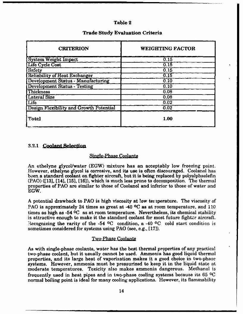
Table 2
Trade Study Evaluation Criteria
CRITERION WEIGHTING FACTOR
System Weight Impact 0.15Life Cycle Cost 0.15Safety 0.15Reliability of Heat Exchanger 0.15Development Status - Manufacturing 0.10Development Status - Testing 0.10Thickness 0.08Lateral Size 0.08Life 0.02Design exibility and Growth Potential 0.02
Totel 1.00
3.2.1 Coolant Selectio
Single-Phase Coolants
An ethelyne glycol/water (EGW) mixture has an acceptably low freezing point.However, ethelyne glycol is corrosive, and its use is often discouraged. Coolanol hasbeen a standard coolant on fighter aircraft, but it is being replaced by polyalphaolefin(PAO) ([13], [14], [15], [16]), which is much less prone to decomposition. The thermalproperties of PAO are similar to those of Coolanol and inferior to those of water andEGW.
A potential drawback to PAO is high viscosity at low teriperature. The viscosity ofPAO is approximately 24 times as great at -40 oc as at room temperature, and 110times as high as -54 oC as at room temperature. Nevertheless, its chemical stabilityis attractive enough to make it the standard coolant for most future fightcr aircraft.Aecognizing the rarity of the -54 OC condition, a -40 oC cold start condition issometimes considered for systems using PAO (see, e.g., [171).
Two-Phase Coolants
As with single-phase coolants, water has the best thermal properties of any practicaltwo-phase coolant, but it usually cannot be used. Ammonia has good liquid thermalproperties, and its large heat of vaporization makes it a good choice in two-phasesystems. However, ammonia must be pressurized to keep it in the liquid state atmoderate temperatures. Toxicity also makes ammonia dangerous. Methanol isfrequently used in heat pipes and in two-phase cooling systems because its 65 oCnormal boiling point is ideal for many cooling applications. However, its flammability
14
results in a safety hazard if leaks occur in the system. Dielectric refrigerants such asFC-72 and FC-87 have low freezing points, but poor thermal properties.
3.2.2 Thermal Reguirements - Electronic failure rate is well known to increasewith temperature. Maximum device junction temperature specifications vary with thetype of device, with values ranging typically from 60 OC to 150 oc. A 90 oc maximumjunction temperature was selected for this study.
Two requirements were established for heat flux. First, based on the resultsdiscussed in Section 2, a steady-state heat dissipation of 100 W/cm 2 was selected asrepresentative of near-future high power avionics components. At this design point,the cooler was required to hold the electronics device junction temperature to 90 oc.The second requirement was for a factor of safety (F.O.S.) of 2.0 on heat flux. Thecooler was required to be capable of 200 W/cm 2 heat flux so that it could meet the 100W/cm 2 requirement if operating at an off-design condition. The 90 OC junctiontemperature requirement was not imposed at this higher heat flux.
3.2.3 Geometric ConfimUration - The three applications identified on a fighteraircraft (digital processors, power processors, and embedded apertures) all sharecertain common design constraints. Embedded apertures and digital processors,especially, require thin heat exchangers. Digital processors are often mounted onelectronics boards which are spaced 1.5 cm apart, while space limitation requires tightpackaging of embedded aperture components and their cooling devices. With devicesoften packed in tight arrays, there is little room for heat spreading, so the lateralextent of the heat exchanger must be minimized. Thus, heat exchanger thickness andlateral size requirement were chosen as evaluation factors.
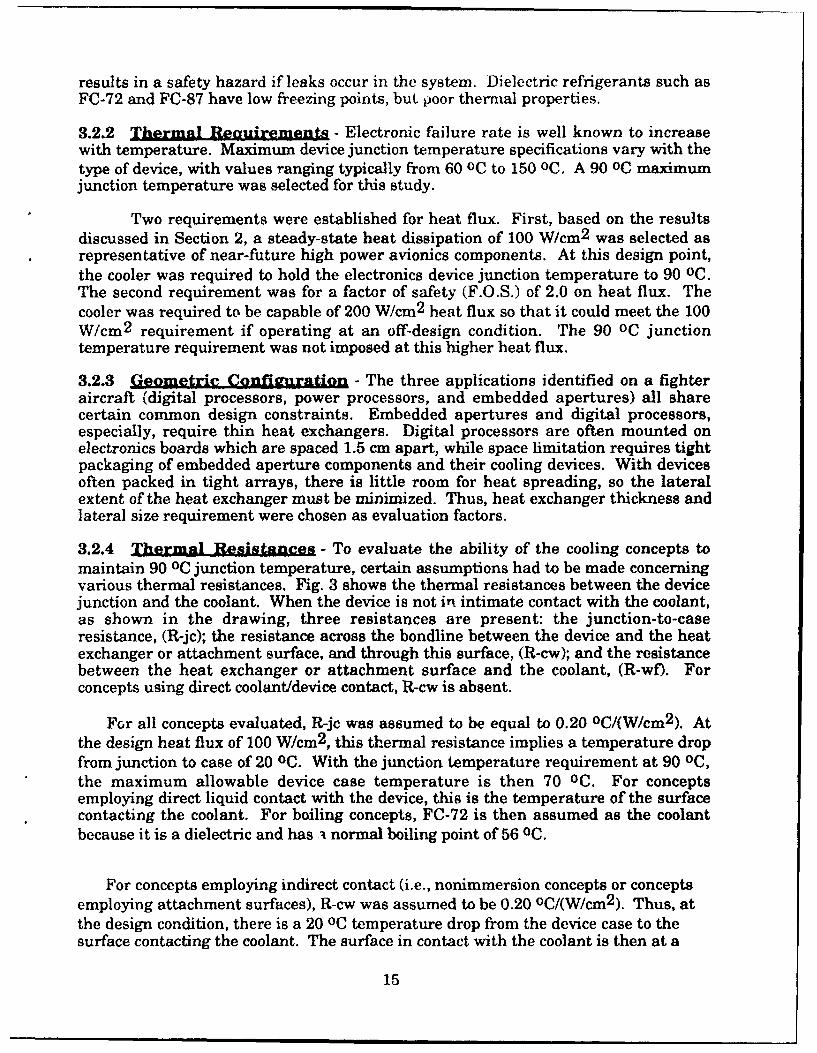
3.2.4 Thermal Resistances - To evaluate the ability of the cooling concepts tomaintain 90 0C junction temperature, certain assumptions had to be made concerningvarious thermal resistances. Fig. 3 shows the thermal resistances between the devicejunction and the coolant. When the device is not in intimate contact with the coolant,as shown in the drawing, three resistances are present: the junction-to-caseresistance, (R-jc); the resistance across the bondline between the device and the heatexchanger or attachment surface, and through this surface, (R-cw); and the resistancebetween the heat exchanger or attachment surface and the coolant, (R-wf). Forconcepts using direct coolant/device contact, R-cw is absent.
For all concepts evaluated, R-jc was assumed to be equal to 0.20 oC/(W/cm 2 ). Atthe design heat flux of 100 W/cm 2 , this thermal resistance implies a temperature dropfrom junction to case of 20 0C. With the junction temperature requirement at 90 oc,the maximum allowable device case temperature is then 70 oc. For conceptsemploying direct liquid contact with the device, this is the temperature of the surfacecontacting the coolant. For boiling concepts, FC-72 is then assumed as the coolantbecause it is a dielectric and has i normal boiling point of 56 0C.
For concepts employing indirect contact (i.e., nonimmersion concepts or conceptsemploying attachment surfaces), R-cw was assumed to be 0.20 OC/(W/cm 2 ). Thus, atthe design condition, there is a 20 oc temperature drop from the device case to thesurface contacting the coolant. The surface in contact with the coolant is then at a
15
HEAT SOURCE(JUNCflON)ELECTRONIC
DEVICE CASE--.., T1i
TCHXSRCURE Rc-W
WALL RUw
COOLANTTFLUID
Figure 3. Definition of Thermal Resistance
maximum temperature of 50 oC. For boiling concepts in this case, FC-87 is assumedas the coolant because it has a normal boiling point of 30 oC.
3.2.5 Coolant Sunnlv Temxerature, - Coolant supply temperatures of 0 OC orgreater were desired in order to minimize penalties to the aircraft environmentalcontrol system.
3.3 Cooling Concepts
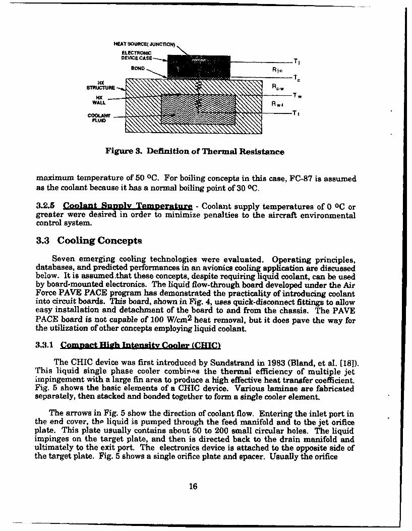
Seven emerging cooling technologies were evaluated. Operating principles,databases, and predicted performances in an avionics cooling application are discussedbelow. It is assumed .that these concepts, despite requiring liquid coolant, can be usedby board-mounted electronics. The liquid flow-through board developed under the AirForce PAVE PACE program has demonstrated the practicality of introducing coolantinto circuit boards. This board, shown in Fig. 4, uses quick-disconnect fittings to alloweasy installation and detachment of the board to and from the chassis. The PAVEPACE board is not capable of 100 W/cm 2 heat removal, but it does pave the way forthe utilization of other concepts employing liquid coolant.
3.3.1 Cmpat teitCoer (CHIC)
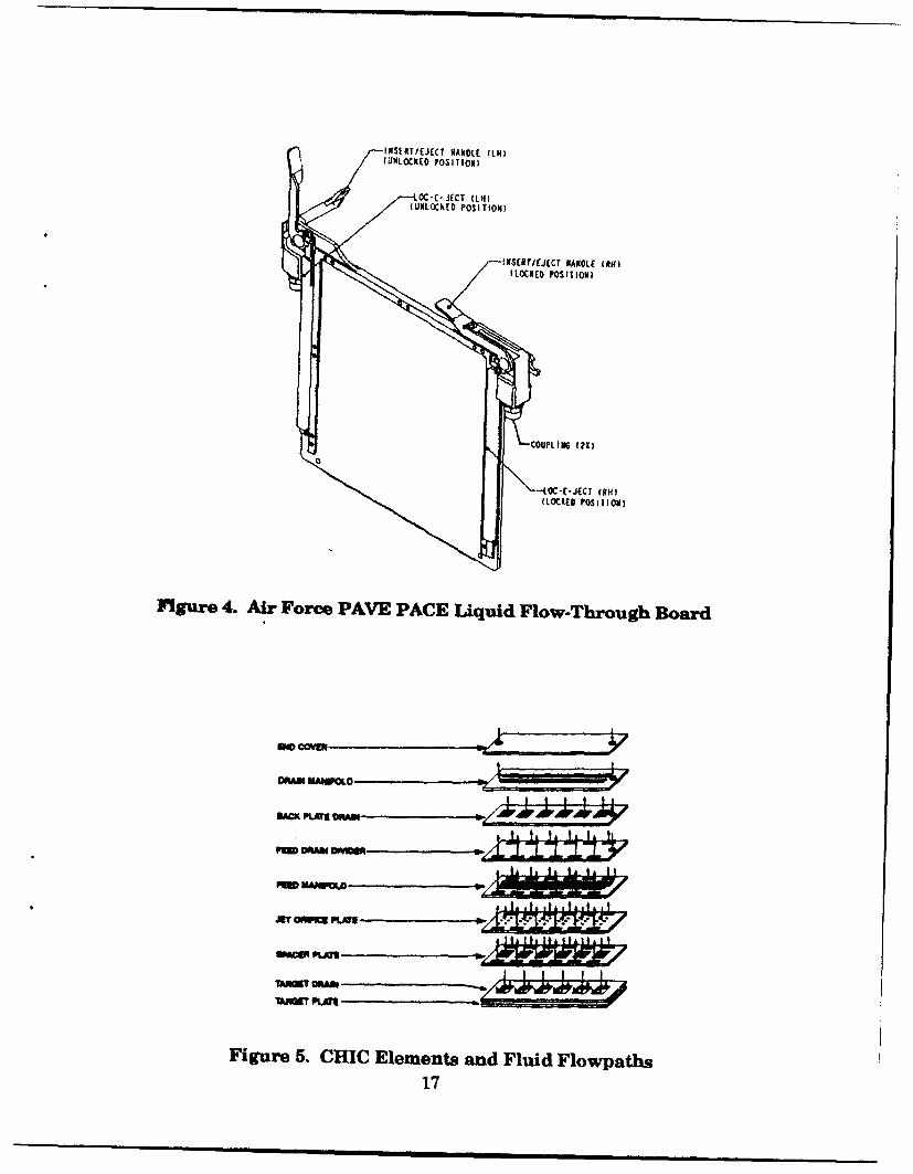
The CHIC device was first introduced by Sundstrand in 1983 (Bland, et al. [181).This liquid single phase cooler combires the thermal efficiency of multiple jetimpingement with a large fin area to produce a high effective heat transfer coefficient.Fig. 5 shows the basic elements of a CHIC device. Various laminae are fabricatedseparately, then stacked and bonded together to form a single cooler element.
The arrows in Fig. 5 show the direction of coolant flow. Entering the inlet port inthe end cover, thb liquid is pumped through the feed manifold and to the jet orificeplate. This plate usually contains about 50 to 200 small circular holes. The liquidimpinges on the target plate, and then is directed back to the drain manifold andultimately to the exit port. The electronics device is attached to the opposite side ofthe target plate. Fig. 5 shows a single orifice plate and spacer. Usually the orifice
16
lINSERT/EJECT RANDLE( 1114(UNLOCKED POSITION)
OC-E- JECT Q(IN
(UNLOCKEDt POSITION)
IXSClTIEJCCT RANDLE (11H)(LOCKED POSITIONI)
(LOCKED POSIHoN)
Figure 4. Air Force PAVE PACE U~quid Flow-Through Board
CAMN MANGOW ...... 111l
I PLM~DA
TAVW DRAM
Figure 5. CHIC Elements and Fluid Flowpaths17
plate and spacer are repeated several times, with each successive orifice plate actingas a target for the jets from the orifice plate immediately upstream. The orifices areoffset by one-half their pitch from plate to plate, so that the liquid impinges on solidmetal, then cascades downward as it passes through subsequent orifice plates. Thegreater the number of plates, the greater the fin effect and thus the higher theo:ective heat transfer coefficient. The penalty for a large number of orifice plates ishigher pressure drop and a thicker heat exchanger.
Databas.& - The original 1983 copper CHIC had a thermal resistance, R-wf, as low
as 0.12 oC/(W/cm 2 ) at a flowrate of about 70 kg/hr using Freon-ll. This device hadse•oen copper orifice plates. The predicted thermal resistance R-wf using PAO in thisde' ice for a flowrate of 35 kg/hr is also 0.12 oC/(W/cm 2 ).
Recently, multiple CHICs in a single board have been built by Sundstrand. Thelaminae are photoetched, then stacked and bonded. Diffusion bonding has beendernonstrated for copper boards and vacuum brazing for aluminum boards, althoughthe copper technology is further developed. The photoetching process allows virtuallyanything that can be drawn to be fabricated, so that the designer has liberty in laying"ov, the locations and sizes of the various CHICs on the board.
Since the 1983 prototype, several versions of the CHIC have been built fromcopper and aluminum. References [11], and [181 through (20], provide heat flux andthirmal resistance measurements on a variety of CHIC devices tested with water,Fr.:.an-11, and Freon-113. Using much of this data, Sundstrand has developed avalidated analytical model to predict the thermal and hydraulic performance ofarbitrary CHIC configurations. Since CHIC coolers have not yet been tested withPAO, the Sundstrand model was used for predicting performance, which is givenbelow.
Predicted Performance - A copper CHIC employing even layers of orifice plates,w,.irh a total thickness of about 0.5 cm, was selected to mi I the thermal requirementsof Section 3.2.2. The design point and performance that were predicted are shown in
*,'.H' 3, along with those of the other six concepts which were evaluated.
ssessmnent - Advantages of the CHIC include its apparent capability to use PAO,1,i; fiowrate requirement, and proven manufacturing process which is flexible to
i:bIgn changes. Thermal performance is predicted to be excellent using PAO,.a1though the CHIC has not yet been tested with the coolant. Thermal expansion,simrr•atch with the chip must also be cowsidered irl the design of copper or aluminum
Y•I Cs.
'i'Tc small orifice diameters required to obtain performance demand attention be paid0, the potential for clogging. The minimum diameter orifice usually considered is 127
w-crons (0.005 in).
The high viscocity of PAO at low temperature calls attention to cold start issues, asmentioned in Section 3.2.1. The room temperature design pressure drop through theCHIC board, not including quick-disconnect pressure drop, and assuming four CHICsoperating in series, and a flowrate per series of CHICs of 35 kgilhr, is 140 kPa (20 psi).A supply/return line pressure drop of 35 kPa (5 psi) is assumed, thus resulting in a 175kPa (25 psi) loop pressure drop, if other components such as filters are neglected. Of
18

Table 3
Predicted Design Points and Performance
Concept Design Point Thermal Resistance(oC/W/cm 2 )
.Coolant CoolantCooling Concept Coolant Flowrate AP Supply R-jc R-cw R-wf R-tot
(kg/hr)** (atm) Temp.(OC)
CHIC PAO 20 1 37 0.20 0.20 0.13 0.53Curved Surface FC-87 480 1 0 0.20 0.20 0.35 0.75
"Evaporative Spray FC-72 35 2 36 0.20 0.00 0.16 0.36Heat Pipe Water N/A*** N/A 37 0.20 0.20 0.12 0.52
Jet Impingement- FC-72 70-280 1 16 0.20 0.00 0.49 0.69Bare Chip
Jet Impingement- FC-87 25-100 1 10 0.20 0.20 0.28 0.68Enhanced Surface I
Microcbannel PAO 35 5 0 0.20 0.2010.50 0.90Pumped Calillary Amnmonia N/E N/E N/E 0.20 0.20 0.15 0.55
Evaporator I I__II___
• These values are extrapolated from test data, conditions, and coolants which areoften different from the identified design points.
• * Based on 1.0 cm 2 chip dissipating 100 W heat flux.•** Also requires PAO flow loop for heat sink.N/E = Not Evaluated
the 140 kPa pressure drop in the CHICs, 99 kPa is incurred through the orifices, and41 kPa through the internal manifolding. For laminar flow, the manifold pressuredrop is proportional to dynamic viscosity. However, orifice pressure drop isproportional to jet velocity squared and independent of viscosity. Therefore, asubstantial portion of the pressure drop is unaffected by fluid viscosity. Calculationsat -40 °C indicate that a flowrate of 4 kg/hr (11% of the room temperature value) isobtainable for a loop total pressure drop of 280 kPa (40 psi); 10 kg/hr (29% of the roomtemperature value) can be provided for a pressure drop of 700 kPa (100 psi). Whilethese flowratee are well below the design flowrates necessary to cool 100 W/cm 2 heat-dissipating chips, they appear sufficient to initiate coolant movement and allow for thesystem to begin to warm up.
3.3.2 Curved Chnnnl Flow with Subcooled Boilin
This concept employs turbulent flow and bouyancy forces to assist the boilingprocess. As shown in Fig. 6, the heat source is mounted on the concave side of acurved flow channel. A subcooled liquid flowing through the channel experiencesnucleate boiling as it passes over the heat source. Since the bubbles are less densethan the surrounding liquid m2dium, the induced radial acceleration drives thebubbles from the surface. Bubble removal is also enhanced by shear forces in the
|Q

a 0
LIQUD OUT
LIOUIDI CONDUCTVE•MATERIAL •
SLIBCOOL.D BOILING
Figure & Curved Chalnel Flow with Subcooled Boiling
turbulent flow. Secondary flow resulting from the curved flowpath may also affectbubble rew- '. The efficient bubble removal process increases heat transfercoefficient a.." forestalls boiling burnout. High radial forces can be created with evenmoderate flowrates. For example, with a 2.54 cm radius of curvature, a flow velocityof 5 m/s will induce a 100 g radial acceleration.
Fig. 6 depicts an electronics device mounted outside the flowpath in order toprovide a smooth flow channel. Gu, et al. [21] found that nonflush mounting of heatsources inside the flow channel leads to significantly reduced values of critical heatflux (CHF).
1atabase - Research into augmenting the boiling process with inducedaccelerations dates back to the 1950s, and includes such cooling applications as rocketmotor cases, space-based cooling in the absence of gravity, and the need to understandthe effects of acceleration on boiling (see, e.g., [22] through [28]). These investigationsestablished a correlation that CHF is proportional to the fourth root of acceleration foracceleration levels over 10 "g's." More recently, Leslie, et al. [29] demonstrated theadvantages of replacing linear flow with curved surface flow in order to increase CHFand thereby gain better performance with X-ray sources.
While most of the earlier investigators used water as the coolant, some recentwork has been done using coolants with lower freezing and boiling points. Gu, et al.[21] tested subcooled boiling of FC-72 in both straight and curved channels. Theirresults show, at a flow velocity of 4 m/s, about a 45% increase in CHF using a curvedchannel as compared to a straight channel. CHF was also found to be sensitive tovelocity and the amount of subcooling. In a straight channel, CHF increased by asmuch as 90% as velocity increased from I m/s to 4 m/s. CHF also increased by 50% to100% when subcooling of the FC-72 was increased from 0.5 OC to 20 oC. Thus, radialacceleration did not appear to be the greatest driver in establishing CHF.
Using FC-72, Leland and Chow [30] found that channel curvature had only a weakeffect on CHF. They report that any enhancement in CHF due to channel curvaturediminishes as subcooling increases.
Predicted Performan - The heat flux data published by Gu, et al. [21] using FC-72 was used to predict performance. Their data indicate that substantial subcooling
20

and high velocity flow are needed to meet the F.O.S. requirement on heat flux statedin Section 3.2.2. The design point and predicLed performance are shown in Table 3.
Data from Leland and Chow [30] suggest that channel height must be at least 1mm to preclude CHF degradation. Given this minimum height, a 1-cm channel width(to match the nominal chip width), and a requisite 8 m/s flow velocity in order to meetF.O.S. requirements, the design flowrate is 480 kg/hr.
A - An advantage of this concept is its simplicity. Fabrication should berelatively inexpensive. Because the liquid is subcooled, there is no need for acondenser, and the flow loop resembles that of a single phase cooler. The concept hasseveral disadvantages, the most important being that a significant benefit obtained byinducing radial accelerations has not yet been clearly established for heat flux levelsand coolants which are applicable to electronics cooling.
3.3.3 Evanoratie Sp=ay Cooler
Evaporative spray cooling makes use of the low thermal resistance obtainablethrough the evaporation process while minimizing flowrate requirement. As depictedin Fig. 7, a pressurized, subcooled liquid is forced through a nozzle, atomized, and theresultant droplets impinge upon the heated surface. Under optimum operatingconditions, approximately 20% to 30% of the liquid is vaporized upon impinging. Thisis a much greater percentage than for subcooled boiling, so the required flowrate islower.
PRESSURIZED PLENUM (SUBCOOLED LIQUID)
UOUDNPLDROPLETS ed1UOUIDIVAPO'*.@ý 0.0 CIRCULAR NOZZLE
MIXTURE OUT 0 THI LIQUID FILM
A A A AA A 4% A A A ^ A A A A ^ AA
A A A A A AIpUfT~AO A
Figure 7. Evaporative Spray Cooling.
One of the purposes of cooling in the form of a spray is to forestall the dryout of theheated surface which results from film boiling. Given a sufficiently high impingementvelocity, it is believed that the droplets can, up to a point, penetrate the developingvapor film on the surface of the chip and delay surface dryout, thereby raising CHF.
Databas- References [31] through [34] describe earlier work in this field. Waterwas used as the working fluid, and heat fluxes as high as 2000 W/cm 2 (at a surfacesuperheat of 200 oc) proved that evaporative spray was a viable high flux coolingtechnique. Tilton, et al. [35] summarized these earlier efforts and concluded that theheat fluxes obtained from them varied considerably due to the sensitivity of thermalperformance to spray conditions. Consequently, parametric testing was performed tounderstand the influence of spray conditions on thermal performance, which is
21

documented in references [36] through (401. Tests have recently been performed usingthe dielecric coolant FC-72, with a maximum CHF obtained of about 300 W/cm 2 [41].The latest versions of this cooler are about 1 cm thick.
Predicted Performance - The reference (41] data on FC-72 was used to predictdesign operating conditions to meet the requirements in Section 3.2.2. The designpoint and predicted performance are shown in Table 3. For all actively pumped two-phase concepts, the coolant was assumed to be subcooled by 20 oc to preclude pumpcavitation; this is reflected in the coolant supply temperature shown.
s - Advantages of evaporative spray cooling include high heat fluxcapability and low thermal resistance between the coolant and the device. The totalthermal resistance from device junction to coolant is the lowest of the concepts studied.Flowrate requirements are also low. A substantial database with parametricvariations has been amassed. Finally, redundancy is offered by using multiple nozzlesper chip.
A potential disadvantage of this concept is that, being a two-phase system, thecooling cycle is more complex than that of a single phase system. In an acceleratingsystem such as a fighter aircraft, vapor collection and condensation presentchallenges. Using a dielectric refrigerant such as FC-72 or FC-87 would requirestocking an additional coolant, thus impacting maintainability costs.
The high impingement velocity (-20 m/s or more) calls attention to chip integrity.Tests have been conducted only on copper heaters, so data is unavailable to determinewhether or not erosion would be a problem. If it is, then the device could be protectedby bonding a shield or applying a conformal coating..
3.344 Real ipe
The operation of heat pipes is well documented (see, e.g., Skrabek (42)). The pipe islined with a wicking material which in turn is saturated with a liquid working fluid.The liquid is evaporated at the heated end of the pipe, and the resulting pressureincrease drives the vapor toward the opposite end, where the vapor rejects heat to aheat sink and condenses. The condensate is then pulled by capillary force back to theevaporator end to complete the cycle.
Database - Much work has gone into developing heat pipes for cooling avionics,and heat pipe cold planes have entered military air vehicle operation. Heat pipes areused for cooling discrete electronics on printed wiring boards on the ERIS missileoptical seeker, as well as the LANTIRN targeting and navigation pods for the F-18.Both of these heat pipes are of copper construction, have a sintered powder copperwick construction, and employ water as the working fluid. These heat pipes havepassed environmental testing including storage to -54 oc. The sintered wick structureseems to allow the water to freeze without damaging the heat pipe. Both theseapplications have low local heat flux capabilities compared to the requirements of thisstudy.
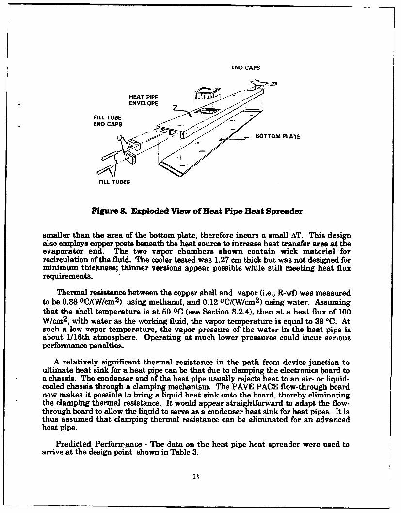
An advanced heat pipe heat spreader [43] for cooling high power devices has beenbuilt and tested to over 100 W/cm 2 with methanol, and to over 200 W/Cm 2 with water(44]. This device, depicted in Fig. 8, uses vapor chambers to spread the vapor over anarea much larger than the area of the heat source. The condenser, which is slightly
22
END CAPS
HEAT PIPE •--
ENVELOPE ,.
FILL TUBEEND CAPS
BOTTOM PLATE
FILL TUBES
Figure 8. Exploded View of Heat Pipe Heat Spreader
smaller than the area of the bottom plate, therefore incurs a small AT. This designalso employs copper posts beneath the heat source to increase heat transfer area at theevaporator end. The two vapor chambers shown contain wick material forrecirculation of the fluid. The cooler tested was 1.27 cm thick but was not designed forminimum thickness; thinner versions appear possible while still meeting heat fluxrequirements.
Thermal resistance between the copper shell and vapor (i.e., R-wf) was measuredto be 0.38 oC/(W/cm2 ) using methanol, and 0.12 oC/(W/cm 2 ) using water. Assumingthat the shell temperature is at 50 OC (see Section 3.2.4), then at a heat flux of 100W/cm 2 , with water as the working fluid, the vapor temperature is equal to 38 *C. Atsuch a low vapor temperature, the vapor pressure of the water in the heat pipe isabout 116th atmosphere. Operating at much lower pressures could incur seriousperformance penalties.
A relatively significant thermal resistance in the path from device junction toultimate heat sink for a heat pipe can be that due to clamping the electronics board toa chassis. The condenser end of the heat pipe usually rejects heat to an air- or liquid-cooled chassis through a clamping mechanism. The PAVE PACE flow-through boardnow makes it possible to bring a liquid heat sink onto the board, thereby eliminatingthe clamping thermal resistance. It would appear straightforward to adapt the flow-through board to allow the liquid to serve as a condenser heat sink for heat pipes. It isthus assumed that clamping thermal resistance can be eliminated for an advancedheat pipe.
Predicted Perforwa= - The data on the heat pipe heat spreader were used toarrive at the design point shown in Table 3.
23

The high forces of acceleration experienced in a fighter aircraft were of concern inevaluating heat pipes. The smallest peak acceleration levels, usually felt along thelateral axis of the aircraft, are typically about 2 g's. Even if heat pipes were orientedalong this axis, a 2-g acceleration is great enough to significantly degrade the heatpipe performance. A similar conclusion was also reached by Beam [45]. This problemmigeht be overcome by limiting the length of the heat pipes in order to minimizecapillary pumping distance.
&sgsaMent - Advantages of the heat pipe heat spreader include its relativesimplicity and low weight. A disadvantage is performance degradation under highacceleration levels. Because this concept employs heat spreading, it is better suitedfor Eingular or relatively widely spaced electronics devices than for devices mounted incompact arrays. Since water is required as the coolant to obtain the required thermalperformance, start-up performance from a cold start condition must be determined.
3.3.5• e gement with Subcooled Boilin
This concept utilizes both high single-phase heat transfcr and boiling. A subcooledliquid is forced through a nozzle. Single or multiple nozzles may be used, and theymay be circular or slotted. Fig. 9 depicts the configuration selected for evaluation,which uses a single slotted nozzle. Subcooled boiling augments the single-phase heatremoval, and is enhanced by shear forces from the turbulent flow.
PRESSURIZED PLENUM (SUBCOOLED LIQUID)
CONFINED JET
CONFINEMENT WALL-. EN, ANCEMENT SURFACE(OPT IONAL)
............... CIRCUIT BOARD:......
Figure 9. Jet Impingement With Subcooled Boiling.This configuration uses a slotted nozzle of very narrow width and extending the length of the device top -duce a linear jet as shown. After impinging on the device or enhancement surface, the liquid turns90 degrees and exits, still in the subcooled state, "into and out of the page" relative to the drawing.
Two variations of this concept were evaluated: one where the bare chip is cooleddirectly by the jet, and the other where a finned surface (called an enhancementsurfkce) is bonded to the chip. In both cases, the electronics board is immersed in adielectric coolant. Bare chip cooling often provides the lower thermal resistance bybringing the coolant into direct contact with the chip. Surface enhancement, on theother hand, provides higher heat flux capability.
b - Jet impingement boiling for the purpose of cooling electronics has
received considerable attention recently. Ma and Bergles (46] provide an overview of
24
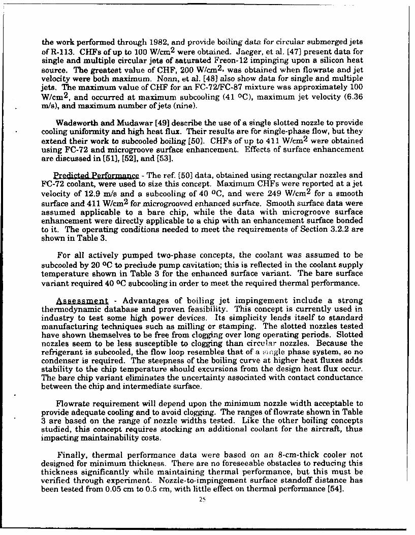
the work performed through 1982, and provide boiling data for circular submerged jetsof R-113. CHFs of up to 100 W/cm 2 were obtained. Jaeger, et al. [47] present data forsingle and multiple circular jets of saturated Freon-12 impinging upon a silicon heatsource. The greatest value of CHF, 200 W/cm 2 , was obtained when flowrate and jetvelocity were both maximum. Nonn, et al. [48] also show data for single and multiplejets. The maximum value of CHF for an FC-72/FC-87 mixture was approximately 100W/cm 2 , and occurred at maximum subcooling (41 OC), maximum jet velocity (6.36m/s), and maximum number of jets (nine).
Wadsworth and Mudawar [49] describe the use of a single slotted nozzle to providecooling uniformity and high heat flux. Their results are for single-phase flow, but theyextend their work to subcooled boiling [50]. CHFs of up to 411 W/cm 2 were obtainedusing FC-72 and microgroove surface enhancement. Effects of surface enhancementare discussed in [51], [52], and [53].
redicted Performance - The ref. [50] data, obtained using rectangular nozzles andFC-72 coolant, were used to size this concept. Maximum CHFs were reported at a jetvelocity of 12.9 m/s and a subcooling of 40 oC, and were 249 W/cm 2 for a smoothsurface and 411 W/cm2 for microgrooved enhanced surface. Smooth surface data wereassumed applicable to a bare chip, while the data with microgroove surfaceenhancement were directly applicable to a chip with an enhancement surface bondedto it. The operating conditions needed to meet the requirements of Section 3.2.2 areshown in Table 3.
For all actively pumped two-phase concepts, the coolant was assumed to besubcooled by 20 oc to preclude pump cavitation; this is reflected in the coolant supplytemperature shown in Table 3 for the enhanced surface variant. The bare surfacevariant required 40 oC subcooling in order to meet the required thermal performance.
A- Advantages of boiling jet impingement include a strongthermodynamic database and proven feasibility. This concept is currently used inindustry to test some high power devices. Its simplicity lends itself to standardmanufacturing techniques such as milling or stamping. The slotted nozzles testedhave shown themselves to be free from clogging over long operating periods. Slottednozzles seem to be less susceptible to clogging than circular nozzles. Because therefrigerant is subcooled, the flow loop resembles that of a single phase system, so nocondenser is required. The steepness of the boiling curve at higher heat fluxes addsstability to the chip temperature should excursions from the design heat flux occur.The bare chip variant eliminates the uncertainty associated with contact conductancebetween the chip and intermediate surface.
Flowrate requirement will depend upon the minimum nozzle width acceptable toprovide adequate cooling and to avoid clogging. The ranges of flowrate shown in Table3 are based on the range of nozzle widths tested. Like the other boiling conceptsstudied, this concept requires stocking an additional coolant for the aircraft, thusimpacting maintainability costs.
Finally, thermal performance data were based on an 8-cm-thick cooler notdesigned for minimum thickness. There are no foreseeable obstacles to reducing thisthickness significantly while maintaining thermal performance, but this must beverified through experiment. Nozzle-to-impingement surface standoff distance hasbeen tested from 0.05 cm to 0.5 cm, with little effect on thermal performance [54].
25

3.3.6 Mierochannel Cooler
Conventional microchannel coolers, first introduced by Tuckerman and Pease [55], areliquid single phase heat exchangers that operate in the laminar flow regime. Despitethese two thermally undesirable characteristics, microchannels provide high heatremoval by exploiting two features: high aspect ratio flow passages and large fin area.Nusselt number for fully developed laminar flow in rectangular passages is known toincrease with passage aspect ratio. A 10:1 aspect ratio channel gives a Nusseltnumber about double that of a square channel. A typical microchannel cooler is shownin Fig. 10. The narrower the channels, the greater the fin area, and the higher theeffective heat transfer coefficient. A drawback to using narrow channels is highpressure drop. Increasing channel depth has beneficial results both in terms of heattransfer effectiveness and in pressure drop. Deeper channels provide greater fin area,thus permitting a lower flow velocity for a given mass flowrate, which in turn leads toE lower pressure drop.
Heat Input
Figure 10. Microchannel Cooler
Da1 ~as - A large percentage of the work done on microchannels has dealt withetching them into silicon [55], [56], (57]. Much progress has also been made onmetallic and ceramic microchannels, mostly for the purpose of cooling laser diodesf58], [59], [60], [61]. A listing of microchannel designs, operating conditions, and.thermal performances from several sources is provided by Phillips [62].
The experiments performed to date have generally used water as the coolant.T'herefore, the heat fluxes found in most of the prior investigations are higher thanwI.at would have been obtained using an aircraft-compatible coolant such as PAO. Onthe other hand, many previous microchannels were significantly limited in thicknessix' .rder to meet the constraints imposed by laser diode applications. Heat fluxcapability is sensitive to microchannel thickness, and increases substantially as thethickness increases. The thickness requirement imposed by avionics coolingapplications is not as severe as for laser applications; therefore, thicker microchannelsc,,.n help offset the negative effects of using a thermally poorer coolant than water.
Manufacturing efforts to date have stressed single microchannels dedicated tocooling single heat sources - usually on the order of one square centimeter footprint.To enable cooling multiple chips mounted on a board, current manufacturingprocesses would require tying together many individual microchannels. This may becompared to CHIC manufacturing processes where an entire board containingmultiple 03HICs can be fabricated as a single unit. No similar multicooler fabricationtechnique for microchannels could be found in this study.
26
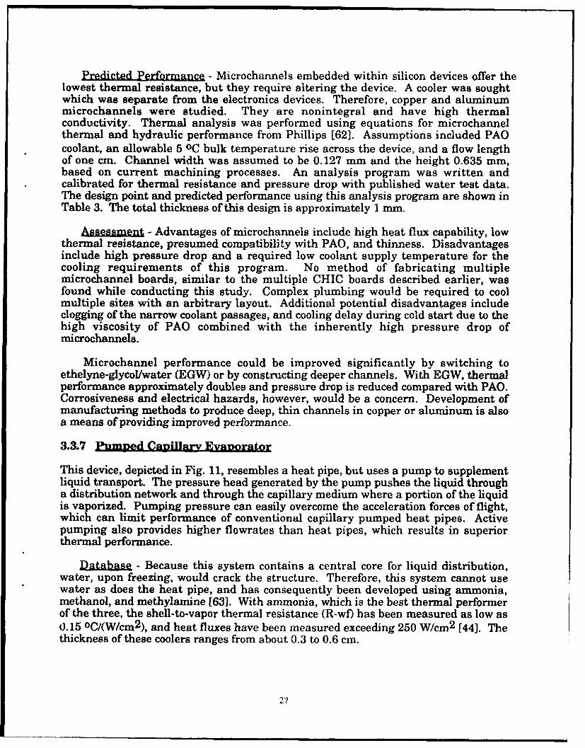
Predicted Performance - Microchannels embedded within silicon devices offer thelowest thermal resistance, but they require altering the device. A cooler was soughtwhich was separate from the electronics devices. Therefore, copper and aluminummicrochannels were studied. They are nonintegral and have high thermalconductivity. Thermal analysis was performed using equations for microchannelthermal and hydraulic performance from Phillips [62]. Assumptions included PAOcoolant, an allowable 5 oC bulk temperature rise across the device, and a flow lengthof one cm. Channel width was assumed to be 0.127 mm and the height 0.635 mm,based on current machining processes. An analysis program was written andcalibrated for thermal resistance and pressure drop with published water test data.The design point and predicted performance using this analysis program are shown inTable 3. The total thickness of this design is approximately 1 mm.
s - Advantages of microchannels include high heat flux capability, lowthermal resistance, presumed compatibility with PAO, and thinness. Disadvantagesinclude high pressure drop and a required low coolant supply temperature for thecooling requirements of this program. No method of fabricating multiplemicrochannel boards, similar to the multiple CHIC boards described earlier, wasfound while conducting this study. Complex plumbing would be required to coolmultiple sites with an arbitrary layout. Additional potential disadvantages includeclogging of the narrow coolant passages, and cooling delay during cold start due to thehigh viscosity of PAO combined with the inherently high pressure drop ofmicrochannels.
Microchannel performance could be improved significantly by switching toethelyne-glycol/water (EGW) or by constructing deeper channels. With EGW, thermalperformance approximately doubles and pressure drop is reduced compared with PAO.Corrosiveness and electrical hazards, however, would be a concern. Development ofmanufacturing methods to produce deep, thin channels in copper or aluminum is alsoa means of providing improved performance.
3.3.7 Pumped CapillAry Eva1orator
This device, depicted in Fig. 11, resembles a heat pipe, but uses a pump to supplementliquid transport. The pressure head generated by the pump pushes the liquid througha distribution network and through the capillary medium where a portion of the liquidis vaporized. Pumping pressure can easily overcome the acceleration forces of flight,which can limit performance of conventional capillary pumped heat pipes. Activepumping also provides higher flowrates than heat pipes, which results in superiorthermal performance.
Database, - Because this system contains a central core for liquid distribution,water, upon freezing, would crack the structure. Therefore, this system cannot usewater as does the heat pipe, and has consequently been developed using ammonia,methanol, and methylamine [63]. With ammonia, which is the best thermal performerof the three, the shell-to-vapor thermal resistance (R-wf) has been measured as low as0.15 oC/(W/crn2 ), and heat fluxes have been measured exceeding 250 W/cm 2 [44]. Thethickness of these coolers ranges from about 0.3 to 0.6 cm.
27

COVER SHEET
POROUS WICK ..STRUCTURE
LIQUID DISTRIBUTIONLIQUID/VAPOR
"POROUS WICK COLLECTION MANIFOLD
STRUCTURE '
COVER SHEET
Figure 11. Actively Pumped Capillary Evaporator (Exploded View)
Predicted Performance - The predicted design point and thermal performanceusing ammonia are shown in Table 3.
g - Advantages of the actively pumped capillary evaporator include highdemonstrated heat flux and low thermal resistance. Its greatest disadvantage in itspresent state of development is its reliance on a toxic, corrosive, or flammable coolant.Conversion to a more benign coolant would be required to make this concept moreviable.
3.3.8 O2ther Coneeta - Several other concepts were studied but were not pursued indetail because they were assessed as not capable of meeting the 100 W/cm2 heat fluxrequirement. The PAVE PACE flow-through board, illustrated in Figure 4, ig limitedto about 10-20 W/cm 2 heat flux when junction temperature must be maintained at 901C. Thermoelectric coolers likewise are limited to about the same heat flux level. Acooling concept receiving recent attention is microencapsulated phase change material(PCM) introduced into a coolant such as PAO to form a slurry [64]. The PCM, whichcan be a pai affin or other material with suitable melting temperature, is encapsulatedin a protective shell such as a polymer. The latent heat that the PCM provides raisesthe effective heat capacity of the liquid significantly. The thermal benefit is feltmainly in terms of reduced flowrate requirement, not in increased heat flux capability.
3.4 Concept Comparisons
Table 4 presents the results of the trade study in summary form. Each of theconcepts evaluated in detail is rated against the evaluation criteria which wereidentified in Section 3.1.1. For each criterion, two scores are provided: a raw scorefrom 1 to 3, 3 being the best; and a weighted score, which is the raw score multipled bythe weighting factor assigned to the particular criterion. Discussions of the scoresassigned, by criterion, are provided in the following paragraphs.
28

Table 4
Trade Study Scoring Results
COOLING CONCEPT
Raw Score * / Weighted Score
Weighting Jet - Evap. Heat Jet- Micro- Curved PumpedCRITERION Factor CHIC Enhanced Spray Pipe Bare channel Channel Capillary
Surface Surface Evap.Weight 15 3 2 3 3 1 1 1 2Impact 45 30 45 45 15 15 15 30Life Cycle 15 2 2 2 2 2 2 2 2Cost 30 30 30 30 30 30 30 30Safety 15 3 3 3 3 3 3 3 1
________ 45 45 45 45 45 45 45 15Reliability 15 3 3 2 2 3 3 3 1
45 45 30 30 45 45 45 15
Mfg. Status 10 3 2 1 2 202 2 1 3 3____ 30 20 10 20 20 20 10 30
Testing 10 3 3 3 3 3 2 2 3Status 30 30 30 30 30 20 20 30Thickness 8 3 2 3 3 2 3 ... 2 3Thicknes 8_3_ 24 16 24 24 16 24 16 24Lateral Size 8 3 3 3 2 1 3 3 2 3 3 "
_____24 24 24 8 24 24 24 24Life 2 2 2 2 2 2 2 2 2
__ __ _ 4 4 4 4 4 4 4 4
Flexibility 2 3 3 3 3 3 3 2 3and Growth 6 6 6 6 6 6 4 6
TotalWtd. 100 283 250 248 242 235 233 213 208Score
Raw Score: 1= Poor 2 = Fair 3 = Good
It would seem desirable to compare the maximum heat flux capability or minimumthermal resistance offered by the concepts. To make a fair comparison, however, isimpossible without imposing equal constraints upon each concept. Eact concept couldrealize significant performance improvement by using exorbitant flowrate, fin area,thickness, or pressure drop. The approach taken here is to compare these operatingparameters given equal thermal performance requirements, and, thereby, indirectlyevaluate thermal performance. The effect of thermal performance on theseparameters is manifested under "System Weight Impact" discussed in the followingsection.
29

3.4.1 System Weight ImUact - If total heat load is large, then the heat exchangeroperating conditions will have a discernible impact upon aircraft take-off gross weight(TOGW). TOGW increases when a high coolant flowrate or a low coolant supplytemperature is required. The weight of the heat exchanger and its operationalpressure drop also impact TOGW, though to a lesser degree. Examination of Table 3shows that the CHIC and evaporative spray cooler impose the least demands onflowrate and coolant supply temperature.
The sensitivity of fighter aircraft TOGW to HFHE operating parameters wasestimated for the case of PAO as coolant. An advanced fighter in its baseline missionrole was used for the analysis. A vapor cycle system was assumed as the intermediatecooling loop for transporting heat from the HFHE loop to the aircraft fuel heat sink.The analysis was performed using the McDonnell Douglas Computer-AidedEnvironmental Control System (CAECS) software. CAECS, an enhanced version ofthe Wright Laboratory AECS software, computes steady-state flow rate, pressuredrop, temperature, and enthalpy at each location In the system. It then computescomponent weight and power requirements based upon flow conditions. TOGWpenalty is calulated by multiplying applicable penalty factors (for a representativeadvanced fighter aircraft) by weight, power, and ram air flowrate from CAECS.
The calculated sensitivities of TOGW to coolant flowrate, pressure drop, supplytemperature, and fixed weight of the HFHE, are shown in Figures 12 through 15, forthe case of a 2 kW total heat load. The results are expressed in terms of ATOGW froman assumed baseline condition. The results indicate that TOGW is most sensitive tocoolant supply temperature and coolant flowrate, and less sensitive to HFHE weightand pressure drop.
The predicted design operating points presented in Table 3 may be used todetermine relative impact on TOGW of HFHE concepts employing PAO. Because theflowrates given in Table 3 are based upon a 100 W heat load, they must be multipliedby 20 before being applied to Figure 13, which is for a 2 kW heat load. As an exampleof TOGW sensitivity, for a 2 kW total heat load, TOGW is predicted to be 14 kg (31 lb)higher when employing the microchannel than when employing the CHIC. At highertotal heat loads, this difference would of course be greater. For this assessment, theweight of the CHIC and microchannel heat exchangers were not used due to lack ofinformation. Fig. 15, however, indicates that heat exchanger weight will have arelatively small impact on TOGW.
30

10-
*Co~a. I ow Rate 350 kg/hr. HFHEý ý:ressure Drop 15 psi
5 ~~Total heat Load -2 kW
Biat50ne Condition
-15
0 10 20 30 40
Coolant In~let Temperature (IC)
Figure 12. Sensitivity of Aircraft Take-Off Gross Weight to Cooltnt SupplyTemperature.
20.*PAO Coolant*Coolant Iinet Termperature = 10 OC*HFHE Pressure Drop -15 psi
15 Total Heat Load - 2 !W
10~0 . 50.100.150.200
.~Co ln Fl.....w. R.t .... gh....
Figure~~~~~~~...... ..... Se..i.t of A..rf .ae .f.r. egt oCoat lwa
3.. ...'.. ...

1 6 1 1 1 1 1 1 7I I I I I i"* PAO Coolant"- Coolant Flow Rate - 350 kg/hr
12 - Coolant Inlet Temperature - 10 °C* Total Heat Load - 2kW 10
0 8
0-
o 4 -
0 -
Baseline Condition
-4 " .
0 20 40 60 80 100
Pressure Drop In HFHE (psi)
Figure 14. Sensitivity of Aircraft Take-Off Gross Weight to HFHE PressureDrop.
-- Results are
independent of type ofS.....coolant, flow rate,............... .... c ol nt fow ra e .... . ............ ........... q.-e.°
-- pressure drop, and -- -
-coolant temperature - -
. ,.°.......... ........ .°. ... ...... .... ........ °... ............ ..... ..... .... ...... ...... ......
........ .. ........ 0-
............ . ....... ............ *-Baseline Condition0
....... ... ............i ....... ..... ..... ... .......... ."• ... ... .............. ...... ...
-2 - 0 1 2
A Weight from Baseline (ib)
Figure 15. Sensitivity of Aircraft Take-Off Gross Weight to HFHE Structural
and Contained Coolant Weight.
32

3.4.2 Life Cycle Cost
A qualitative, comparative assessment of life cycle cost (LCC) was made. It isrecognized that the accuracy of an LCC estimate is limited to the extent of conceptdevelopment discussed in Section 3.4.4. For example, concepts lagging inmanufacturing status often appear to be less complex (and thus less costly) thanconcepts which are further developed.
The LCC analysis, shown in Table 5, is broken into three categories: developmentcost, manufactunng cost, and maintenance cost. Development cost ratings are baseddirectly on development status ratings (see Table 7). Manufacturing cost ratingsinclude considerations such as complexity, number of parts, material, tolerances, andmanufacturing processes. Maintenance cost ratings are based on complexity andsystem impact. An important system impact is the choice of coolant. Since futurefighter aircraft will use PAO, the CHIC and microchannel cooler, if employing PAO,reduce maintainability cost in this regard. Concepts requiring the use of anothercoolant ;ill require the stocking of this coolant and thus will increase maintainabilitycosts.
The column designated "average rating" was rounded to the nearest whole numberfor use in the Table 4 Trade Study Scoring Results.
Table 5
Life Cycle Cost Assessments
CONCEPT Development Manufacturing Maintenance AverageCost Cost Cost Rating
CHIC 3 2 2 2.3
Curved Channel 1 3 2 2.0
Evaporative 2 2 1 1.7Spray ....
Heat Pipe 2 2 3 2.3
Jet Impingement 2 2 2 2.0(both variants)Microchannel 2 1 2 1.7
Pumped 3 2 1 2.0Capillary
Evaporator
Scoring: 1 = Poor 2 = Fair 3 = Good
33

3.4.3 Safety andRliAbiity
Reliability ratings of the heat exchangers were made by identifying the number ofpotential failure modes as well as by assessing complexity. Like LCC ratings,reliability ratings are qualitative and relative. Table 6 shows potential failure modesand complexity factors which entered into the reliability assessment. These wereidentified by an "X" when they applied to a particular concept. The total number of"X's" were then used to give an overall assessment of reliability.
Table 6
Reliability Assessment
COMPLEXITYPOTENTIAL FAILURE MODES FACTORS
-..- Cooling
Contact Boiling Pump HFHE Loop Total/
CONCE•PT Leakage Clogging Conduct- Insta- Cavi- High g Complex- Complex- Rating'ance bilities tation ity ity
CHIC X X X X 4/3
CurvedChannel X X X X 4/3
Spray X X X X X X 6/2
Heat Pipe X X X X X 5/2
Jet(enhanced X X X X 4/3
surface)
Jet(bare X X X 3/3
3urface)Micro-channel X X X X 4/3
PumpedCapillary X X X X X X X 7/1
Evaporator -
* For "Total/Rating," "Total" refers to the number of'X's" a concept received, and
"Rating" refers to the score (1, 2, or 3) given for use in Table 4, the trade studyassessment. "Totals" of 3 and 4 yielded a score of"3," 5 and 6 a score of"2," and 7or higher, a score of"l."
34

All the concepts employ a liquid coolant and thus are considered susceptible toleaks. Curved channel flow and jet impingement both utilize slotted flow channelswhich tend to resist clogging. The heat pipe, being a sealed unit with no activepumping, will also resist clogging. The other concepts employ small feature sizeswhich present clogging potential. All the concepts, with the exception of evaporativespray and the bare surface variant of boiling jet impingement, rely on heat conductionfrom the electronics device across an interface to the wetted surface. Poor thermalcontact, or degradation of contact over time, could lead to electronics failuxe. Boilinginstabilities, which occur near CHF, are further potential causes for failure. TheCHIC and microchannel cooler are single phase systems and are thus immune toboiling instabilities. T'he boiling concepts are also vulnerable to pump cavitation. Asmentioned in Section 3.3.4, the heat pipe suffers reduced performance or dryout underhigh adverse acceleration. The concepts identified as "complex" require the mostnumber of parts and/or the most intricate parts. The heat pipe would require furtherdevelopment to overcome high g-forces, which presumably would lead to increasedcomplexity. The spray cooler and pumped capillary evaporator require a condenser inthe coolant loop and are thus considered to entail relatively complex coolingsubsystems.
Safety appears to present no problem except for the pumped capillary evaporator,which uses a flammable or toxic coolant.
3.4.4 Development StatuSan.1d Risk, - Testing and manufacturing status areincluded in the tradeoff because they not only impact risk, but they also affectconfidence in the thermal performance predictions. Most of the concepts, because theyare still being developed, are in some need for further testing or packagingdevelopment. Further development might result in improved thermal performance,or, perhaps, uncover unexpected problems which lead to reduced performance.
The development status of the various concepts is compared in Table 7. The statusof both manufacturing and testing each concept is rated. Under both these categories,the status is further subdivided into "proposed cooler" and 'similar coolers." Thissubdivision is necessary because some devices, an example being the microchannelcooler, have been extensively developed for other applications, but lag development forhigh flux avionics cooling applications with multiple heat sources. In the case of themicrochannel cooler, the extensive test and manufacturing databases developed forsilicon coolers and laser diode applications certainly contribute to reducing the risk inthe development of future devices, and thus are accounted for under the column"similar coolers."
The "average scores" shown in Table 7 were rounded to the nearest whole numberfor use in the Table 4 Trade Study Scoring Results.
Most of the concepts are supported with ample test data. Practical designs andproven manufacturing methods have been demonstrated for the CHIC, microchannel,pumped capillary evaporator, and heat pipe, whereas the other concepts have beenmainly built for laboratory thermal performance demonstrations.
35
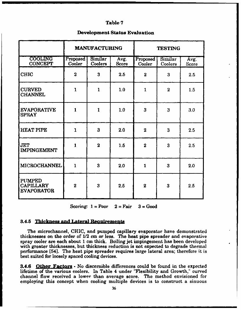
Table 7
Development Status Evaluation
MANUFACTURING TESTING
COOLING Proposed Similar Avg. Proposed Similar Avg.CONCEPT Cooler Coolers Score Cooler Coolers Score
CHIC 2 3 2.5 2 3 2.5
CURVED 1 1 1.0 1 2 1.5CHANNEL
EVAPORATIVE 1 1 1.0 3 3 3.0SPRAY
HEAT PIPE 1 3 2.0 2 3 2.5
JET 1 2 1.5 2 3 2.5IMPINGEMENT
MICROCHANNEL 1 3 2.0 1 3 2.0
PUMPEDCAPILLARY 2 3 2.5 2 3 2.5EVAPORATOR
- -J
Scoring- 1=Poor 2=Fair 3=Good
3.4.5 Thickuns Tteral B.o,,irementa
The microchannel, CHIC, and pumped capillary evaporator have demonstratedthicknesses on the order of 112 cm or less. The heat pipe spreader and evaporativespray cooler are each about 1 cm thick. Boiling jet impingement has been developedwith greater thicknesses, but thickness reduction is not expected to degrade thermalperformance [54]. The heat pipe spreader requires large lateral area; therefore it isbest suited for loosely spaced cooling devices.
3.4.6 Other Fetors.- No discernible differences could be found in the expectedlifetime of the various coolers. In Table 4 under "Flexibility and Growth," curvedchannel flow received a lower than average score. The method envisioned foremploying this concept when cooling multiple devices is to construct a sinuous
36

flowpath, with devices mounted above each bend of the flow channel. This method, if
employed, restricts device mounting to periodic locations.
3.5 Conclusions - Overall Comparisons
Assessments were made of various cooling technologies for the application ofcooling high power avionics devices aboard fighter aircraft, Each concept appearscapable of meeting the thermal requirement of removing 100 W/cm 2 of heat flux whilemaintaining a 90 oc junction temperature. Additionally, each concept ranks highly incertain applications, as attested to by the many uses for the concepts indicated in thereferences.
General conclusions are given below, with the concepts listed in order of theirranking in the trade study:
1. The CHIC cooler incurs the least system impact. Not only does it incur lowTOGW penalty, but it also should be able to use PAO, the aircraft coolant ofchoice. It has a good manufacturing development status. Tests need tobe conducted using PAO to verify performance pre~dictions, and cold start mustbe addressed in the design.
2. Jet impingement with subcooled boiling and microgroove surface enhancementoffers the temperature stability that boiling provides without the need of acondenser. The use of slotted nozzle safeguards against clogging.Development of thinner modules will be required for most avionics uses. Likeevaporative spray, this concept requires stocking an extra coolant.
S. Evaporative spray cooling incurs low TOGW penalty. It requires a condenserand the stocking of a dielectric coolant, which add to complexity andmaintenance costs.
4. High performance heat pipe heat spreaders have demonstrated adequate heatremoval rates and offer low system impact. They require lateral room for heatspreading and are susceptible to acceleration forces.
5. Jet impingement with subcooled boiling and no surface enhancement requiresa relatively high flowrate to meet the thermal requirements.
6. Microchannel coolers offer thin construction and should be able to use PAO.Drawbacks include high pressure drop, low coolant supply temperaturerequirement, and manufacturing complexity if multiple sites require cooling.
7. Curved channel flow with subcooled boiling is still being developed as a way toincrease heat flux capability in electronics cooling applications.
8. Pumped capillary evaporators can overcome acceleration forces which limit heatpipes. These systems currently use coolants which are flammable, toxic, orcorrosive.
The work reported in this section is also described in [65].
37

SECTION 4
REFERENCES
1. A. Bar-Cohen, 'Thermal Management of Air- and Liquid-Cooled MultichipModules," IEEE Transactions of Components. Hybrids, and ManufacturingTecndology, p. 159, June 1987.
2. "Mitsubishi puts 400k gates into 0.8 micron array," Electronic ComonentNewil p. 48, May 1991.
3. 1991 Integrated Device Technology, Inc., "RISC R3000A, R3001, R3051 FamilyProduct Information," p.40.
4. "It Looks Like an '89 Debut for the Cray-3 After All," Electronic, December1988, p. 32.
5. Motorola Semiconductor Technical Data, "MM16M5ECL Multichip Module,"
1990.
6. "Cooling a Hot Computer Chip," The New York Times, September 20, 1989.
7. McDonnell Aircraft Company, Pave Pace contract F33615-89-C-1110, 1989.
8. J. Keller, "Bell Labs Has Cool Idea for SEM-E Boards," Military & AerosnaceEietronicL January 1991.
9. V. Temple, "Advances in MOS-Controlled Thyristor Technology," IloweLr Contrland Inteligent Motion, November 1989, p.12 .
10. McDonnell Aircraft Company, MI)C Report 91B0281, "RF Wafer ScaleIntegration System Studies," May 1991.
11. M. G. Grote, R. E. Hendron, H.W. Kipp, and J. R. Lapinski, "Test Results ofWafer Thin Coolers at Heat Fluxes from 5 to 125 W/cm 2 ," SAE Paper #880997,18th Intersociety Conference on Environmental Systems, July 11-13, 1988.
12. M. Mackowski, "Requirements for High Flux Cooling of Future AvionicsSystems," SAE Paper No. 912104, September 1991.
13. MIL-C-87252, "Military Specification - Coolant Fluid, Hydrolytically Stable,Dielectric," 2 November 1988.
14. "Mini-Task 19, "Feasibility of Replacing Coolanol with PAO Coolant in F-15Radar Liquid Cooling System," McAIR Internal Memo, November 1989.
15. ROYCO 602 Product Bulletin and Material Safety Data Sheet, November 1987.
16. BRAYCO 889 Technical Data Sheets, Revised, September 1987.
17. Hughes Aircraft Company Report No. 2001-D, "F-15 R&M PAO Coolant Study,"38

March 1988.
18. T. J. Bland, R.E. Niggemann, and M. B. Parekh, "A Compact High IntensityCooler (CHIC)," SAE Paper No. 831127, July 1983.
19. T. J. Bland, M. P. Ciaccio, R. S. Downing, and W. G. Smith, "The Development ofAdvanced Cooling Methods for High-Power Electronics," SAE Paper No. 901962,October 1990.
20. R. E. Hendron, "Test Results of Five Types of Wafer Thin Coolers," McDonnellDuuglas Corp. Te,:h-ical N-te E465-01, June 1988.
21. C. B. Gu, L. C. Chow, and J. E. Beam, "Flow Boiling in a Curved Channel,"ASME HTD-Vol. 119, in Heat Transfer in High Energy/High Flux Applications,pp. 25-32, 1989.
22. W. R. Gambill and N. D. Greene, "Boiling Burnout with Water in Vortex Flow,"Chemical Engineering Progress (vol. 54, No. 10), October 1958.
23. H. Merte and J. A. Clark, "Pool Boiling in an Accelerating System," J. leatTrfer, pp. 223-242, August 1961.
24. R. Viskanta, "Critical Heat Flux for Water in Swirling Flow," Letter to the Editorin Nuclear Science and Engineerin : 10 (1961).
25. W. R. Gambill and R. D. Bundy, "High-Flux Heat Transfer Characteristics ofPure Ethelyne Glycol in Axial and Swirl Flow," A.I.Ch.E Journal, Vol. 9, No. 1,pp.55-60, January 1963.
26. H. J. Ivey, "Acceleration and the Critical Heat Flux in Pool Boiling HeatTransfer," Proc. Instn. Mech. Engrs., Vol. 177, No. 1, 1963.
27. C. P. Costello and J. M Adams, "The Interrelation of Geometry, Orientation, andAcceleration in the Peak Heat Flux Problem," A.I.Ch.E. Journal, Vol. 9, No. 5, pp.663-671, September 1963.
28. Z. L. Miropol'skiy and V. Pikus, "Critical Boiling Heat Fluxes in CurvedChannels," Heat Transfer - Soviet Research, Vol. 1, No. 1, pp. 74-79, January1969.
29. B. Leslie, A. Neukermans, T. Simon, and J. Foster, "Enhanced Brightness X-RaySource," J. Vac. Sci. Technol. B 1 (4), October-December 1983.
30. J. E. Leland and L. C. Chow, "Effect of Channel Height and Radius of Curvatureon Forced Convection Boiling in a Rectangular Channel," AIAA-92-0250,January 1992.
31. L. Wachters and N. Westerling, "Heat Transfer from a Hot Wall to ImpingingWater Droplets in the Spheroidal State,"!Chem. Eng. Sci., Vol. 21, pg. 1231, 1966.
32. S. Toda, "A Study of Mist Cooling," Heat Transfer - Jananese Research, Vol. 1 (3),pg. 39, 1972.
39
33. C. Bonacina, S. Del Guidice, and S. Comini, "Dropwise Evaporation," J. HeaTransfer- Vol. 101, pg. 441, 1979.
34. G. Y. Eastman and D. M. Ernst, "High Power Density Evaporative Cooling(HIPDEC)," Final Report, Air Force Weapons Laboratory, Kirtland AFB,September 1982.
35. D. E. Tilton, L. C. Chow, and E. T. Mahefkey, "High Power Density EvaporativeCooling," AIAA-87-1536, June 1987.
36. D. E. Tilton, M. R. Pais, and L. C. Chow, "High Power Density Spray Cooling,"VIRDC TR-89-2O%02, July 1989.
37. M. R. Pals, D. E. Tilton, L. C. Chow, and E. T. Mahefkey, "High-Heat-Flux, Low-Superheat Evaporative Spray Cooling," AIAA-89-0241, 1989.
38. M. Sehlnbey, M. Pals, and L. Chow, "Effect of Surface Material Properties andSurface Characteristics in Evaporative Spray Cooling," J. Thermophysics andkaTr=sfer, Vol. 6, No. 3, pp. 505-512, July 1992.
39. M. S. Sehmbey, M. R. Pais, and L. C. Chow, "A Study of l~iamond LaminatedSurfaces in Evaporative Spray Cooling II," Intl. J. Sci. and Techn. of CondensedMatter Films, Thin Solid Films, Vol. 212, pp. 25-29, 1992.
40. M. R. Pais, L. C. Chow, and E. T. Mahefkey, "Surface Roughness and its Effectson the Heat Transfer Mechanism in Spray Cooling," J.Hat Trans., Vol. 114, pp.211-219, February 1992.
41. D.E. Tilton, C.L. Tilton, M.R. Pais, and M.J. Morgan, "High Flux Spray Coolingin a Simulated Multichip Module," to be presented at the ASME 1992 Natl. HeatTrans. Conf., August 9-12, 1992, San Diego, CA.
42. E. A. Skrabek, "Heat Pipe Design Handbook," NASA-CR-134264, August 1972.
43. N. Gernert, "The Planar Heat Pipe Spreader," Thermacore, Inc., 1989.
44. J. Toth, Thermacore, Inc., personal communication, 1991.
45. J. Beam, "Topics of Aircraft Thermal Management," SAE Paper No. 881381,October 1988.
46. C. F. Ma, and A. E. Bergles, "Boiling Jet Impingement Cooling of SimulatedMicroelectronics Chips," Heat Transfer in Electronic Eouipmenat, HTD-Vol. 28,ASME, pp. 5-12.
47. R. C. Jaeger, et al., "High Heat Flux Cooling for Silicon Hybrid MultichipPackaging," IEEE Trans. on Components. Hybrids. and ManufacturingTechnolg, Vol. 12, No. 4, December 1989.
48. T. Norn, Z. Dagan, and L. M. Jiji, "Jet Impingement Flow Boiling of a Mixture ofFC-72 and FC-87 Liquids on a Simulated Electronic Chip," HTD-Vol. 111, HeaTransfer in Electronics, Book No. H00503 (ASME), pp. 121-128, 1989.
40
49. D. C. Wadsworth and I. Mudawar, "Cooling of a Multichip Electronic Module byMeans of Confined Two-Dimensional Jets of Dielectric Liquid," HTD-Vol. 111,Heat Transfer in Electrglif, Book No. H00503 (ASME), pp. 79-87, 1989.
50. D.C. Wadsworth and I. Mudawar, ir1ancement of Single-Phase Heat Transferand Critical Heat Flux from an Ultra-High-Fl.,x Simulated Microelectronic HeatSource to a Rectangular Impinging Jet of Dielectric Liquid," AdvancesinElectronic Packaging 1992 - Proc. 1992 Joint ASME-JSME Conf. on Elec. Pckg.,Vol. 1, pp. 143-151, April 1992.
51. I. Mudawar and T. M. Anderson, "High Flux Electronic Cooling by Means of PoolBoiling - Part 1: Parametric Investigation cf the Effct3 of Conlant Variation,Pressurization, Subcooling, and Surface Augmentation," HTD-Vol. 111, HeatTransfer in Electronics, Book No. H00503 (ASME), pp. 25-34, 1989.
52. I. Mudawar and D.E. Maddox, "Enhancement of Critical Heat Flux from HighPower Microelectronic Heat Sources in a Flow Channel," J. Elec. Packaging, Vol.112, pp. 241-248, September 1990.
53. T. M. Anderson and I. Mudawar, "Microelectronic Cooling by Enhanced PoolBoiling of a Dielectric Fluorocýarbon Liquid," Proc. 1988 National Heat TransferConf., HTD-vol. 96, ASME, pp. 551-560, 1988.
54. I. Mudawar, personal communication, 1992.
55. D. B. Tuckerman and R. F. W. Pease, "High Performance Heat Sinking for VLSI,"IEEE Electronic Device Lettrs, EDL-2, 126, 1981.
56. D. Mundinger, et al., "Demonstration of High Performance Silicon MicrochannelHeat Sinks for Laser Diode Array Cooling," Appl. Phys. Lett. 53, 1030, 1988.
57. D. Mundinger, R. Beach, W. Benett, and R. Solarz, "Laser Diode Cooling for HighAverage Power Applications," Laser Diode Technology and AD2lications, Proc.SPIE 1043, pp. 351-358, 1989.
58. R. E. Hendron, et al., "Stackable Wafer Thin Coolers for High Power Laser DiodeArrays," Laser Diode Technology and Applications, Proc. SPIE 1219, 1990.
59. J. R. Lapinski, and M. G. Grote, "Isothermal Multi- Passage Cooler," U.S. Patent
No. 5,005,640, 1991.
60. "3M Microchanneled Structures," 3M Advanced Information Release, 1989.
61. M. G. Grote, R. E. Hendron, and D. J. Burnham, "High Aspect RatioMicrochannel Cooler," Patent Pending, Patent Disclosure made 17 May 1991.
62. R. J. Phillips, "Microchannel Heat Sinks," The Lincoln Laboratory Journal. Vol.1, Number 1, 1988.
63. J. Rosenfeld, "Active Two Phase Cooling of Optics," Thermacore Final Reportprepared for Los Alamos National Laboratories, Contract No. 9X28-1476G-7, May1990.
41

64. D.P. Colvin, J.C. Mulligan, and Y.G. Bryant, "Enhanced Heat Transport inEnvironmental Systems Using Microencapsulated Phase Change Materials," SAEPaper No. 921224, July 1992.
65. E.M. Flynn, "Evaluation of Cooling Concepts for High Power AvionicsApplications," SAE paper No. 921942, October 1992.
42
U.S. GOVERNMENT PRINTING OFFICE 7Sfl-113


![[Addressee] - Rochester Museum and Science Center · [Addressee] [Address] [City], [State], [Zip] Rochester Museum & Science Center 657 East Avenue Rochester, NY 14607-2177 Non-Profit](https://static.fdocuments.us/doc/165x107/5ec8c31f736ae00a8b4360d4/addressee-rochester-museum-and-science-center-addressee-address-city.jpg)