VSM 300 shale shaker manual... · SECTION 1.4 - TECHNICAL SPECIFICATIONS 1.4.1 EQUIPMENT...
66
A division of Rig Technology Limited A Varco Company VSM 300 SHALE SHAKER OPERATING & MAINTENANCE MANUAL __________________________________________________________________________________________________Iss ue 1 Rev: 02 (Nov. 97) THULE RIGTECH VSM 300 SHALE SHAKER OPERATING MANUAL Head Office - U.K. RIGTECH Badentoy Crescent Badentoy Park Portlethen Aberdeen AB12 4YD SCOTLAND U.K. Tel: (01224) 343600 Fax: (01224) 343700
Transcript of VSM 300 shale shaker manual... · SECTION 1.4 - TECHNICAL SPECIFICATIONS 1.4.1 EQUIPMENT...

A division of Rig Technology Limited
A Varco Company
VSM 300 SHALE SHAKER
OPERATING & MAINTENANCE MANUAL
__________________________________________________________________________________________________Iss
ue 1 Rev: 02 (Nov. 97)
THULE RIGTECH
VSM 300
SHALE SHAKER
OPERATING MANUAL
Head Office - U.K.
RIGTECH Badentoy Crescent
Badentoy Park Portlethen
Aberdeen AB12 4YD SCOTLAND U.K. Tel: (01224) 343600 Fax: (01224) 343700

A division of Rig Technology Limited
A Varco Company
VSM 300 SHALE SHAKER
OPERATING & MAINTENANCE MANUAL
__________________________________________________________________________________________________Iss
ue 1 Rev: 02 (Nov. 97)
INDEX
1.0 LEADING PARTICULARS 1.1 CE Declaration of Conformity 1.2 Equipment Data Sheets 1.3 General Equipment Details
1) Equipment Description
2) Principle of Operation
3) Strength of Components 1.4 Technical Specifications
1) Equipment Specification
2) Electrical Specifications
3) Paint Specification
4) Recommended Cable Specifications
5) Noise Data
2.0 INSTALLATION 2.1 Utility Requirements
1) Electrical
2) Air Supply
3) Water Supply
2.2 Installation Instructions
1) Introduction
2) Health and Safety
3) Equipment Location
4) Unpacking, Lifting and Handling Instructions
5) Installation Procedure
♦ Mechanical ♦ Electrical

A division of Rig Technology Limited
A Varco Company
VSM 300 SHALE SHAKER
OPERATING & MAINTENANCE MANUAL
__________________________________________________________________________________________________Iss
ue 1 Rev: 02 (Nov. 97)
INDEX
2.0 INSTALLATION (Cont’d) 2.3 Commissioning Procedure
1) Commissioning - Checklist
2) Test Running - Checklist
3.0 OPERATION 3.1 Functional Description of Equipment 3.2 Health and Safety 3.3 Operating Instructions
1) Start-Up
2) Normal Running
3) Controlled Shutdown
4) Emergency Shutdown 3.4 Screen Data
1) Screen Details
2) Screen Selection
3) Screen Repair Procedure
4) Screen Storage
5) Screen Washing
6) Screen Fitting Procedure
7) Screen Removal Procedure

A division of Rig Technology Limited
A Varco Company
VSM 300 SHALE SHAKER
OPERATING & MAINTENANCE MANUAL
__________________________________________________________________________________________________Iss
ue 1 Rev: 02 (Nov. 97)
INDEX 4.0 MAINTENANCE
4.1 Introduction
4.2 Health and Safety
4.3 Routine Maintenance
4.4 6000 Hour Maintenance Schedule
4.5 Mounting Springs 4.6 Parts Replacement Procedure
1) Pneumoseal Clamping System
2) Drive System - Removal
3) Drive System - Refit
4) Torque Setting Chart
5) Nord Lock Information 5.0 PARTS DATA 5.1 Parts List
5.2 Cross Sectional Drawings 6.0 FAULT FINDING
6.1 Fault Finding/Correction Checklist

A division of Rig Technology Limited
A Varco Company
VSM 300 SHALE SHAKER
OPERATING & MAINTENANCE MANUAL
__________________________________________________________________________________________________Iss
ue 1 Rev: 02 (Nov. 97)
INDEX
7.0 DRAWINGS
314-001 Basket General Arrangement 314-002 Vibratory Drive General Arrangement 314-003 Vibratory Drive Clump Weight Housing Assy 314-008 VSM 300 Lifting Details 314-009 Shaker Schematic Wiring Diagram (Sheets 1 & 2) 314-012 Shaker Bonding Arrangement
314-016 Shaker Termination Drawing
314-017 Shaker Cable Schedule
8.0 SUB VENDOR MANUALS 1) Inverter Manual 2) Thermistor Protection Units
9.0 SERVICE BULLETINS

A division of Rig Technology Limited
A Varco Company
VSM 300 SHALE SHAKER
OPERATING & MAINTENANCE MANUAL
__________________________________________________________________________________________________Iss
ue 1 Rev: 02 (Nov. 97)
INDEX 1.0 LEADING PARTICULARS 1.1 CE Declaration of Conformity 1.2 Equipment Data Sheets 1.3 General Equipment Details
1) Equipment Description
2) Principle of Operation
3) Strength of Components
1.4 Technical Specifications
1) Equipment Specification
2) Electrical Specifications
3) Paint Specification
4) Recommended Cable Specifications
5) Noise Data

A division of Rig Technology Limited
A Varco Company
CE DECLARATION OF CONFORMITY
Issue 1 Rev: 02 (Nov. 97) Section 1.0 Page 1 of 16
VSM 300 : SHALE SHAKERS
Description of Equipment
Machine Type : VSM 300 SHALE SHAKER Serial Number : Thule Rigtech hereby declare that the machinery supplied by the Company complies with the relevant essential Health and Safety requirements of the Machinery Directive 89/392/EEC, 91/368/EEC and associated amendments 93/44/EEC and 93/68/EEC enacted in the United Kingdom by The Supply of Machinery (Safety) Regulations 1992 (SI1992/3073)
Company Details
Name: : Thule Rigtech Address : South College Street Aberdeen Grampian SCOTLAND AB11 6LB
Responsible Person : Gordon Harrison
The equipment has been manufactured in accordance with Thule Rigtech requirements by the following approved Sub-Contractor:
Company Details
Name : Reekie Manufacturing Address : Orchardbank Forfar Tayside SCOTLAND DD8 1UQ
The machinery has been designed to meet the requirements of the following transposed harmonised European Standards:
EN 292 Part 1 Safety of Machinery - Basic Concepts, General Principles for Design -
Basic Terminology, Methodology
EN 292 Part 2 Safety of Machinery - Basic Concepts, General Principles for Design -
Technical Principles and Specifications
EN 414 Safety of Machinery - Rules for Drafting and Presentation of Safety Standards
EN 418 Safety of Machinery - Emergency Stop Equipment, Functional Aspects - Principles of Design
EN 60204 - 1 Electrical Equipment
In addition to the above harmonised standards, the equipment has been designed to meet the safety requirements of Health and Safety Executive - Provisions and Use of Work Equipment Regulations 1992
A complete Technical File is available for review at the Thule Rigtech offices.
Signed: .................................................... Date: ................................... Name: Gordon Harrison Position: Service Manager

A division of Rig Technology Limited
A Varco Company
CE DECLARATION OF CONFORMITY
Issue 1 Rev: 02 (Nov. 97) Section 1.0 Page 1 of 16

A division of Rig Technology Limited
A Varco Company
VSM 300 SHALE SHAKER
OPERATING & MAINTENANCE MANUAL
__________________________________________________________________________________________________
Issue 1 Rev: 02 (Nov. 97)
SECTION 1.3 - GENERAL EQUIPMENT DETAILS
1.3.1 EQUIPMENT DESCRIPTION
The VSM 300 Shale Shaker is designed to meet the demands of the oilfield drilling industry and is purpose built to provide a more efficient primary solids removal system. The VSM 300 Shale Shaker is designed on a modular basis thus enabling multi unit installations and flexible configurations to be achieved using standard equipment. The modular design construction is also advantageous on existing rig locations where the equipment can be easily installed into the shaker room through a standard shaker house door. Description of Main Components: ♦ Basket/Drive Assembly
The basket/drive assembly is supplied in accordance with Thule Rigtech standard equipment design and manufacturing process. The vibratory head is fitted with two (2) electric motors which have been manufactured by Brook Hansen in accordance with Thule Rigtech’s standard electric motor specification. The electric motors drive counter rotating shafts which induce vibration into the basket/drive assembly. The basket is supported onto the skid base by four (4) springs.
♦ Skid Base
The skid base is manufactured to form a fluid sump and is located under the basket/drive assembly. It is used to collect the processed mud before it is returned to the mud tanks. Each skid base is manufactured with two (2) exit gates, one at each side, which enables the mud to flow into either an adjacent link section or a site built ditch.
♦ Link Sections
The link sections between the shale shakers are used for the following functions: * Distribution of mud between skid bases * Header tank dump/bypass facility ∗ Access walkway between shale shakers The various options are achieved by opening/closing the appropriate sluice gates on the link section to divert the mud flow as required.

A division of Rig Technology Limited
A Varco Company
VSM 300 SHALE SHAKER
OPERATING & MAINTENANCE MANUAL
__________________________________________________________________________________________________
Issue 1 Rev: 02 (Nov. 97)
1.3.1 EQUIPMENT DESCRIPTION (Continued)
♦ Header Tank Assembly
The header tank units supplied with standard equipment are of a shallow modular design with the following options available: ∗ Header tank only ∗ Header tank with splitter box ∗ Header tank link section ∗ Header tank link section complete with dump valve ∗ Header tank link section complete with splitter box and dump valve ∗ Feed chutes
The configuration of the header tank assembly will be dependent on the number of shale shakers installed.
♦ HVAC Enclosures (where applicable)
The HVAC enclosures mounted onto the shale shakers are in accordance with Thule Rigtech standard design and manufacture. However, the interface connection on the duct outlet may be modified to suit project requirements.
♦ Screens
The screens used on the VSM 300 Shale Shaker can be easily changed out to suit operational conditions.
The following screen types are used: ∗ Top Deck Screens (Scalping Screen)
The top deck of the VSM 300 utilises multi panel pretensioned screens which are used to scalp off large volumes of solids thus protecting the finer mesh of the lower deck screens. The top deck screens are retained in position by pneumoseal clamping systems which enable rapid screen changeout.
∗ Lower Deck Screens (Primary)
The lower deck screen configuration of the VSM 300 comprise four (4) multi panel pretensioned screens. All the screens are mounted on a constant 7° ramp. This screen configuration ensures consistent conveyance of solids thus minimising solids build-up. This results in a higher throughput capacity. The lower screens are retained in position by pneumoseal clamping systems which enable rapid screen changeout.
A division of Rig Technology Limited
A Varco Company
VSM 300 SHALE SHAKER
OPERATING & MAINTENANCE MANUAL
__________________________________________________________________________________________________
Issue 1 Rev: 02 (Nov. 97)
1.3.1 EQUIPMENT DESCRIPTION (Continued)
♦ Screens (Continued)
∗ Secondary Screens (Drying Screens)
Optional screen carriers are provided to enable secondary screens to be fitted to the front of the lower deck screens. This facility should be used to reduce fluid levels on cuttings when drilling with low toxicity or synthetic oil based muds.
The secondary screens and carriers are fitted into ‘C’ channels and held in place by pneumoseal clamping systems which enable rapid screen changeout.
1.3.2 PRINCIPLE OF OPERATION
The configuration on each installation will vary depending on final equipment layout but the basic principle of operation is simple. The mud return flowline is diverted into the splitter box on the header tank and the mud is evenly distributed into the main header box section by manually operating the sliding gate valves located between the splitter box and the header tank. The flow over each shaker is regulated by operating the three (3) sliding gate valves which are located at the feed chute/header tank interface. The processed mud flows through the shale shaker and is discharged back to the mud distribution gutter via the skid base outlet gates. The cuttings from the shale shaker are transported over the screens to the front of the unit and discharged into the cuttings ditch. The shale shaker package has the facility to divert mud returning through the flowline directly into the cuttings ditch by closing the isolation gate valves within the main header tank and opening the dump valve in the bypass link section. The VSM 300 has the optional facility of being fitted with a specifically designed HVAC enclosure should this be required. The design of the enclosure is such that any fumes are contained within the enclosure whilst still allowing adequate access to the equipment for operational and maintenance activities.
1.3.3 STRENGTH OF COMPONENTS
The VSM 300 shale shaker has been subjected to extensive field testing in its 3 year development, to prove suitability of components and design. All materials used in the manufacture are new and of suitable strength to meet the applied working conditions.

A division of Rig Technology Limited
A Varco Company
VSM 300 SHALE SHAKER
OPERATING & MAINTENANCE MANUAL
__________________________________________________________________________________________________
Issue 1 Rev: 02 (Nov. 97)
SECTION 1.4 - TECHNICAL SPECIFICATIONS
1.4.1 EQUIPMENT SPECIFICATION
IMPORTANT NOTE:
The Specification below relates to Thule Rigtech’s standard VSM 300 Shale Shaker. All components listed are manufactured as standard items. Different electrical and dimensional/weight configurations are available and the customer should contact Thule Rigtech directly for information on these. The specifications were correct at time of printing. However, Thule Rigtech’s policy is one of continuous development and therefore Thule Rigtech reserve the right to amend the equipment specification at their discretion. Thule Rigtech accept no liability for loss or damage incurred through the use of the data attached. It is recommended that the customer contact Thule Rigtech for a current status if in doubt.
General
Equipment Type - Elliptical Motion Shale Shaker Vibratory Motion Type - Elliptical Angle of Motion - Fixed Speed of Vibration - Variable Screening Arrangement
Screen Configuration - Dual Deck Screen Type - Scalping - Pretensioned Multi-Panel - Primary - Pretensioned Multi-Panel Site Repairable - Secondary - Pretensioned Panel Site Repairable Solids Drying Deck - Optional Secondary Screen Module (Supplied) All Screen Clamping - Pneumatic
Screen Angles - Scalping - 0º - Primary - 7º - Secondary - 7º Screen Angle Adjustment - No - Fixed Screen Areas - Scalping Screen Deck - 1.91m2 - Primary Screen Deck - 2.44m2 - Secondary Screen Deck - 0.28m2 Mesh Sizes - Refer to Section 3.4.1 of this manual

A division of Rig Technology Limited
A Varco Company
VSM 300 SHALE SHAKER
OPERATING & MAINTENANCE MANUAL
__________________________________________________________________________________________________
Issue 1 Rev: 02 (Nov. 97)
1.4.1 EQUIPMENT SPECIFICATION (Continued) Drive System
Drive System - Electrically Operated - Direct Drive Air System
Air Supply Requirements - Pressure - 80 - 90 psi (for Pneumoseal Clamping System)- Capacity - 0.5 ft3m/in(intermittent)
Dimensions
Type of Unit: Length: Width: Height:
Single 2754 mm 1870 mm 1504 mm
Dual 2754 mm 4070 mm 1504 mm
Triple 3004 mm 6270 mm 1504 mm
Quadruple 3004 mm 8470 mm 1504 mm
Quintuple 3004 mm 10670 mm 1504 mm
N.B. The above dimensions for triple, quadruple and quintuple units are based upon the header box being fitted with a 420 mm wide splitter box.
Please contact Thule Rigtech for details of this feature. Dry Operating Weights
Single Unit - 2338 kg
Dual Unit - 4936 kg
Triple Unit - 7619 kg
Quadruple Unit - 10132 kg
Quintuple Unit - 12650 kg
N.B. The above weights for triple, quadruple and quintuple units are based upon the header box being fitted with a 420 mm wide splitter box.
Please contact Thule Rigtech for details of this feature. Screens - Boxed for Shipping
Scalping (Top) Screen - 16.0 kg
Primary (Lower) Screen - 15.5 kg
Secondary Screen - 3.5 kg
All weights inclusive of packaging.

A division of Rig Technology Limited
A Varco Company
VSM 300 SHALE SHAKER
OPERATING & MAINTENANCE MANUAL
__________________________________________________________________________________________________
Issue 1 Rev: 02 (Nov. 97)
1.4.2 ELECTRICAL SPECIFICATIONS (Continued)
Drive Motor Specification
Make - Brook Hansen : Argus 55 IP56 (Specification modified to meet Thule Rigtech requirements)
Certification - BASEEFA to BS5501 Parts 1 & 5 EExd, Gas Group IIA & IIB, Temperature Class. T4
Rating - 3kW
Voltage - 460V
Frequency - 60Hz (Inverter Rated - 50-70 Hz)
Phase - 3
Thermistors - 140° C cut out
Frame Size - AENV 132 MH
Maximum Speed - 2000 RPM
Speed Control Station Specification Type - CS3
Part No. - CS3XA1YA1ZA1
Manufacturer - MEDC
Certification - BASEEFA No. 96D3435X EExed, Gas Group IIC, Temperature Classification T6
Ingress Protection - In accordance with IP66
Description - Glass Reinforced Polyester, anti-static enclosure with stainless steel cover screws and fitted with the following:
1 Push-button (Momentary-white-inscribed “Boost”) 1 Push-button (Momentary-green-inscribed “Norm”) 1 Push-button (Momentary-white-inscribed “Low”) Contact ratings AC15 500 V 3 amp. Unit to have 1 x M20 cable entry - bottom. Unit engraved with “Speed Control”
Dimensions - (W) 90mm x (H) 200mm x (D) 90mm Fixing Centres - (W) 73mm x (H) 160 mm (4 @ 6 mm dia)
Approx Weight - 1.3 kg

A division of Rig Technology Limited
A Varco Company
VSM 300 SHALE SHAKER
OPERATING & MAINTENANCE MANUAL
__________________________________________________________________________________________________
Issue 1 Rev: 02 (Nov. 97)
1.4.2 ELECTRICAL SPECIFICATIONS (Continued)
Starter Enclosure Specification
Type - GP3 Manufacturer - MEDC
Certification - BASEEFA No. 95D1442 EExd, Gas Group IIB, Temperature Classification T4
Ingress Protection - In accordance with IP65 Description - Cast Iron enclosure with hinged lid (hinges on LHS)
The following components to be mounted on a steel backplate :
a) 1 x 7.5 Kw Frequency Inverter b) 1 x EMC Filter c) 2 x Thermistor Relays d) 1 x 7.5Kw contactor e) 2 x 6 - 9 Amp Thermal Overloads f) 2 x Fault Relays g) 1 x Run Relay h) 3 x Speed Control Relays i) 1 x Stepdown Transformer j) 2 x Primary Control Fuses k) 1 x Secondary Control Fuse l) 1 x Neutral Link m) 17 x DK4Q Double Bank Terminals n) 6 x SAK6 Terminals o) 2 x Ammeters p) 1 x Hours Run Meter q) 2 x Fault Lights r) 1 x Reset Switch 4 x 70mm Indicator windows on hinged lid (inverter, 2 x ammeters, hours run meter) 3 x 25mm Indicator windows on hinged lid (inverter status, 2 x fault lights)
Wiring / Layout - All in accordance with drawings 254-884 and 254-883
Supply - Suitable for 380 - 460 V (480 safe maximum) Entries - Bottom 3 x M25 10 x M20
Dimensions - (W) 582mm x (H) 482mm x (D) 410mm Fixing Centres - (W) 550mm x (H) 420mm (4 @ 12mm dia)
Approx Weight - 225 Kg

A division of Rig Technology Limited
A Varco Company
VSM 300 SHALE SHAKER
OPERATING & MAINTENANCE MANUAL
__________________________________________________________________________________________________
Issue 1 Rev: 02 (Nov. 97)
1.4.2 ELECTRICAL SPECIFICATIONS (Continued) Start/Stop Station Specification
Type - CS2 Part No. - CS2XA1YCS1NN1B2BN Manufacturer - MEDC Certification - BASEEFA No. 96D3435X
EExed, Gas Groups IIC, Temperature Classificaton T6 Ingress Protection - In accordance with IP66 Description - This unit will be manufactured from glass reinforced polyester anti-static enclosure with stainless steel cover
screws and be fitted with the following : a) 1 Start Push-button -
(Momentary - green - inscribed “Start”) b) 1 Stop Latched Mushroom Button -
(Stayput - red, yellow base, inscribed “Stop”) Contact ratings AC15 500V 3 amp Unit to have 2 x M20 cable entries -
one top (EExe plugged), one bottom Dimensions - (W) 90 mm x (H) 150 mm x (D) 135 mm Fixing Centres - (W) 73 mm x (H) 110 mm (4 @ 6 mm dia) Approx Weight - 1.0 Kg
Safety Isolator Specification
Manufacturer - ABB Part No. - GHG262 2301R0007 Certification - PTB No Ex96.D.3134
EExed, Gas Group IIC, Temperature Classification T6 Ingress Protection - In accordance with IP66 to EN60529 Material - Glass-fibre reinforced polyester Approx Weight - 1.5 Kg Dimensions - (W) 110mm x (H) 200mm x (D) 140mm Fixing Centres - (W) 96mm x (H) 150mm (4 @ 7 mm dia) Type - 4 Pole + Auxiliary
Safety switch with lock off facility and cover interlock in the OFF position
Rated Current - 20 amps Rated Voltage - 690V a.c. Ambient Temperature - (-20) to (+40) oC Area of Use - Zones 1 and 2

A division of Rig Technology Limited
A Varco Company
VSM 300 SHALE SHAKER
OPERATING & MAINTENANCE MANUAL
__________________________________________________________________________________________________
Issue 1 Rev: 02 (Nov. 97)
1.4.2 ELECTRICAL SPECIFICATIONS (Continued) Emergency Stop Station Specification
Type - CS1 Part No. - CS1C1NN1B2BN Manufacturer - MEDC Certification - BASEEFA No. 96D3435X
EExed, Gas Group IIC, Temperature Classification T6 Ingress Protection - In accordance with IP66 Description - Glass Reinforced Polyester, anti-static enclosure with
stainless steel cover screws and fitted with: 1 Latched Mushroom Button -
(Stayput-red, yellow base inscribed “Emergency Stop”) Contact rating AC15 500 V 3 amp.
Unit to have 2 x M20 cable entries one top (EExe plugged), one bottom.
Dimensions - (W) 90mm x (H) 100mm x (D) 135mm Fixing Centres - (W) 73mm x (H) 60 mm (4 @ 6 mm dia) Approx Weight - 0.5 kg
1.4.3 PAINT SPECIFICATION Manufacturer - W & J Leigh’s & Co. Surface Preparation - Shotblasted to SA 2½ Coating Systems - Two Pack Epoxy Colours - Thule Green (R4754) - Golden Yellow (BS4800 : 08.6.51) Description - Primer: Epigrip J984 - Two pack Epoxy zinc rich anti-corrosive primer - High Build: Epigrip L653 - Two Pack Epoxy/Resin hi-build containing anti- corrosive pigments - Top Coat: Epigrip M262 - Two Pack Epoxy/Resin pigmented with high quality light fast pigments DFT - Primer - 50 microns - High Build - 150 microns - Top Coat - 50 microns

A division of Rig Technology Limited
A Varco Company
VSM 300 SHALE SHAKER
OPERATING & MAINTENANCE MANUAL
__________________________________________________________________________________________________
Issue 1 Rev: 02 (Nov. 97)
1.4.4 RECOMMENDED CABLE SPECIFICATIONS Cable to Start/Stop, Emergency Stop and Potentiometer Stations
Type : GEXOL - 125 IEC 600V / 1000V
Size : 2.3 mm2 (14 AWG)
No. of Conductors : 4
Part Ref : U37 - 102 - 509 BS
Nominal O/D : 15.7 mm
Approvals : UL E111461 Lloyds 89/0075 DNV E - 1675 through E - 1678 CSA LL80350 ABS 93 - BT52174 - X CCG 9400 - 20 USCG 1987 / 9304 Construction : i) Conductor Soft annealed tinned copper per ASTM B-33. Flexible stranding to Class 5 (IEC 228)
ii) Insulation Chemically cross linked/non chlorinated thermosetting flame retardant polyolefin (XLPO)
iii) Armour Basket weave wire armour per IEEE 45 and IEC 92-3, Bronze
iv) Base Jacket Heavy duty Arctic grade neoprene
v) Outer Jacket Same as base jacket Properties : Flame retardant tested in accordance with IEEE 45
UL temperature rating 100oC Flame test meets requirements of IEEE 45, IEC 92-3 and IEC 332-3
Tested for compatibility with PETROFREE, ENVIROMUL and XP-07 muds and base fluids Application : For machine installations with presence of vibrations on mobile drilling units, aboard ships and offshore fixed and floating production facilities.

A division of Rig Technology Limited
A Varco Company
VSM 300 SHALE SHAKER
OPERATING & MAINTENANCE MANUAL
__________________________________________________________________________________________________
Issue 1 Rev: 02 (Nov. 97)
1.4.4 RECOMMENDED CABLE SPECIFICATIONS (Continued)
Cable from Starter Enclosure to Electric Motors Type : GEXOL - 125 IEC 600V / 1000V Size : 2.3 mm2 (14 AWG) No. of Conductors : 7 Part Ref : U37 - 102 - 521 BS Nominal O/D : 17.7 mm Approvals : UL E111461 Lloyds 89/0075 DNV E - 1675 through E - 1678 CSA LL80350 ABS 93 - BT52174 - X CCG 9400 - 20 USCG 1987 / 9304
Construction : i) Conductor Soft annealed tinned copper per ASTM B-33. Flexible stranding to Class 5 (IEC 228)
ii) Insulation Chemically cross linked, non chlorinated thermosetting flame retardant polyolefin (XLPO)
iii) Armour Basket weave wire armour per IEEE 45 and IEC 92-3, Bronze
iv) Base Jacket Heavy duty Arctic grade neoprene
v) Outer Jacket Same as base jacket Properties : Flame retardant tested in accordance with IEEE 45
UL temperature rating 100oC Flame test meets requirements of IEEE 45, IEC 92-3 and IEC 332-3
Tested for compatibility with PETROFREE, ENVIROMUL and XP-07 muds and base fluids
Application : For machine installations with presence of vibrations on mobile drilling units, aboard ships and offshore fixed and floating production facilities.

A division of Rig Technology Limited
A Varco Company
VSM 300 SHALE SHAKER
OPERATING & MAINTENANCE MANUAL
__________________________________________________________________________________________________
Issue 1 Rev: 02 (Nov. 97)
1.4.4 RECOMMENDED CABLE SPECIFICATIONS (Continued) Cable from Mains Supply to Isolator and Isolator to Starter Enclosure
Type : EO2 600V/1000V TO BS6883 Size : 4.0 mm
2
No. of Conductors : 4 Part Ref : EO204C004 Nominal O/D : 19.3 mm Construction : i) Conductor - Tinned stranded copper ii) Insulation - EPR
iii) Inner Sheath - CSP iv) Armour - Galvanised steel wire braid v) Outer Sheath - CSP Properties : Flame retardant tested in accordance with IEC 332-3 Cat. A Oxygen index of bedding and sheathing: Greater than 32%. H.C.L. Emission less than 5% at 800oc. Melinex tapes below and above braid for ease of stripping.
Application : Power control and distribution cables for fixed installations. 1.4.5 NOISE DATA
Noise Data was obtained from a noise test carried out on a single VSM 300 Shale Shaker unit which was operating under test conditions.
db Total
OCTAVE BAND CENTRE FREQUENCY
31.5 63 125 250 500 1k 2k 4k 8k
78.7 55.3 51.2 59.1 63.7 75.5 73.3 69.7 65.7 59.9
Note: The sound pressure levels are measured at 1m from the VSM 300 and are the logarithmic mean of measured results from various locations around the machine. A full Noise Test Report is available upon request from Thule Rigtech.

A division of Rig Technology Limited
A Varco Company
VSM 300 SHALE SHAKER
OPERATING & MAINTENANCE MANUAL
__________________________________________________________________________________________________
Issue 1 Rev: 02 (Nov. 97)
INDEX 2.0 INSTALLATION 2.1 Utility Requirements
1) Electrical
2) Air Supply
3) Water Supply
2.2 Installation Instructions
1) Introduction
2) Health and Safety
3) Equipment Location
4) Unpacking, Lifting and Handling Instructions
5) Installation Procedure
♦ Mechanical
♦ Electrical 2.3 Commissioning Procedure
1) Commissioning - Checklist
2) Test Running - Checklist

A division of Rig Technology Limited
A Varco Company
VSM 300 SHALE SHAKER
OPERATING & MAINTENANCE MANUAL
__________________________________________________________________________________________________
Issue 1 Rev: 02 (Nov. 97)
SECTION 2.1 - UTILITY REQUIREMENTS
2.1.1 ELECTRICAL
The shale shaker is fitted with two (2) x 3kW, 3 phase electric motors which will operate on 380V - 460V, 50 or 60 Hz supply. The no load current is 3.3 Amps and the maximum load current is 7.5 Amps.
2.1.2 AIR SUPPLY
An air supply is required to inflate the pneumoseal clamping system. Pressure range : 80 - 90 psi Flowrate : 0.5 ft3/min (intermittent) 2.1.3 WATER SUPPLY
Washdown A high pressure wash gun is required for cleaning and washing down the shakers and screens. The cleaning medium must be suitable for the drilling fluid being used.
A division of Rig Technology Limited
A Varco Company
VSM 300 SHALE SHAKER
OPERATING & MAINTENANCE MANUAL
__________________________________________________________________________________________________
Issue 1 Rev: 02 (Nov. 97)
SECTION 2.2 - INSTALLATION INSTRUCTIONS
2.2.1 INTRODUCTION
This section details the installation for Thule Rigtech standard VSM 300 shale shaker equipment. Each installation will vary depending on the circumstances of the rig and any special requirements for the shale shakers.
2.2.2 HEALTH AND SAFETY
Health and Safety are of principle importance to Thule Rigtech for the design, manufacture and operation of equipment. To achieve these objectives, Thule Rigtech have carried out the following assessments on the VSM 300 Shale Shaker: i) Risk Assessments in accordance with the Supply of Machinery (Safety) Regulations 1992
(SI 1992/3073) and Associated Harmonised European Standards. A comprehensive Technical File is available for review at Thule Rigtech’s premises.
ii) COSHH Assessments have been carried out in accordance with Control of Substances Hazardous to Health 1988 (COSHH).
A COSHH Assessment File is available for review at Thule Rigtech’s premises.
2.2.3 EQUIPMENT LOCATION
The VSM 300 is supplied with an integral skid base and can be positioned directly onto the deck or above the sand traps as required.
Note: Structural checks must be carried out on the deck beams to ensure capability of supporting the
applied loads from the shale shaker assembly.
To ensure the package is installed correctly the tolerances on deck levels should be + 25mm.
Link sections can be installed between single shaker units to allow multiple underflow options.

A division of Rig Technology Limited
A Varco Company
VSM 300 SHALE SHAKER
OPERATING & MAINTENANCE MANUAL
__________________________________________________________________________________________________
Issue 1 Rev: 02 (Nov. 97)
2.2.3 EQUIPMENT LOCATION (Cont’d)
The final location of the equipment will depend on a number of factors and since each installation will differ, each case should be carefully considered. Prior to installing equipment a full installation survey should be carried out by a Thule Rigtech service engineer. Please contact Thule Rigtech for details if applicable. As a guide, the following areas should be addressed when considering equipment location.
i) Relationship to Flowline
The shaker distribution chute must be located below the bell nipple to ensure sufficient fall from and to thus avoid back up and/or spillage from the flowline.
ii) Flowline Pipework
Flowline pipework should not include sharp bends or traps for the accumulation of solids. Open ditches/troughs should be used where possible.
Where possible a flowline direct dump capability should be provided.
iii) Flowline Connections
The flowline can enter the header box either from the rear or vertically from the top. On triple, quadruple, quintuple (or larger) configurations, a splitter box is supplied as standard to ensure that the optimum flow distribution is achieved. To assist even flow distribution, the flowline should enter the header tank/splitter box arrangement as centrally as possible. Valves are fitted in specific link sections of multiple units for dumping/bypassing and cleaning purposes.
iv) Underflow Discharge
Shaker skid bases are provided with discharge gates on either side and should be connected to channel the underflow discharge to an appropriate location.
2.2.4 UNPACKING. LIFTING and HANDLING INSTRUCTIONS
i) Introduction
This section details the unpacking, lifting and handling instructions for Thule Rigtech Standard VSM 300 Shale Shaker equipment
A division of Rig Technology Limited
A Varco Company
VSM 300 SHALE SHAKER
OPERATING & MAINTENANCE MANUAL
__________________________________________________________________________________________________
Issue 1 Rev: 02 (Nov. 97)
2.2.4 UNPACKING. LIFTING and HANDLING INSTRUCTIONS (Cont’d)
ii) Unpacking
The equipment will be delivered to site as palletised units and will consist of the following packages:
♦ Shale Shaker Assemblies comprising - Drive System/Basket with or without the skid base and header tank
♦ Link Section(s)
The total number of packages delivered will depend on the quantity and configuration of the system required. Final packing details will be available on dispatch. The equipment shall be unpacked by removing the polythene protective outer cover and by cutting the fixing bands which are used to retain the equipment onto the pallets. Note: Basket securing devices are used to retain the basket onto the skid base and these
should remain secured in position until the equipment is sited in its final location.
iii) Lifting and Handling
The VSM 300 shaker is designed on a modular basis and can be dis-assembled into the following discrete components for installation (if required): Description: Lifting Method: Notes:
Basket/Drive System
Soft slings around the basket or alternatively four (4) x Lifting Eyebolts can be fixed to the basket spring mounts
Spring mounting may be removed to further reduce the basket size
Note: If eyebolts are used please ensure full certification is available
Warning: Basket assembly must not be lifted by the drive motors or any other part of the drive system
Header Tank Soft slings around the box section cross members at the top of the tank Skid Base Four (4) x padeyes - One (1) at each corner
Feed Chute Soft slings/man-handle
Note: For details of lifting configurations refer to Drawing No: 314-008 in Section 7.0

A division of Rig Technology Limited
A Varco Company
VSM 300 SHALE SHAKER
OPERATING & MAINTENANCE MANUAL
__________________________________________________________________________________________________
Issue 1 Rev: 02 (Nov. 97)
2.2.4 UNPACKING. LIFTING and HANDLING INSTRUCTIONS (Cont’d)
iv) Safe Working Load
The safe working load for the skid base is as follows:
Padeyes for skid base (four (4) per skid) S.W.L. = 5.5kN (0.560T) per padeye.
2.2.5 INSTALLATION PROCEDURE
Mechanical Installation
The overall installation of the shaker will depend upon a number of factors including:
♦ Number of shakers to be installed
♦ Retrofitting to existing skid bases
♦ Supply of header tanks
The following steps should be used as a guideline for the installation of a complete shaker package which includes skid bases, link sections and header tanks. In certain locations the full workscope detailed below may not be required. However, this workscope would apply to the most common offshore scenario. The installation to be carried out as follows:
i) Remove the distribution chute from the header tank.
ii) Release the transportation brackets (four (4) per Shaker) and lift the basket/drive assembly off the skid base.
iii) Lift the header tank from the skid base.
iv) If necessary to fit through confined space, remove the drive system from the basket.
v) Position the skid base(s) and link section(s) as required. These are installed in sequence of skid-link section-skid-link section, etc.
vi) Assemble the header tank sections to the skid bases.
vii) Align the skid/header tank assembly and carry out a dimensional check.
viii) Fully weld the skid bases to the deck at the padeye locations with a 6mm fillet weld
ix) Fully seal weld the link sections to the skid bases and header tanks.
x) Seal weld joints between the header tank sections.
xi) Lower the basket assemblies on to skid bases - install the mounting springs and rubber pads.

A division of Rig Technology Limited
A Varco Company
VSM 300 SHALE SHAKER
OPERATING & MAINTENANCE MANUAL
__________________________________________________________________________________________________
Issue 1 Rev: 02 (Nov. 97)
2.2.5 INSTALLATION PROCEDURE (Cont’d)
Mechanical Installation (Cont’d) xii) If required, reinstall the drive system onto the basket and torque the securing bolts to
the specified settings. Refer to Torque Chart in Section 4.6.4.
xiii) Re-install the distribution chutes.
xiv) Position the pneumatic clamping panels as required.
xv) Install a suitable air line from the control panels to shaker pneumatic clamping systems. The air line should be terminated using flexible polythene hose.
xvi) Paint damaged areas/weld areas with recommended paint system.
Electrical Installation For wiring details please refer to the Electrical Schematic Drawing: 314-009 in Section 7 of this Manual.
For termination details refer to Drawing: 314-016.
For cable schedule refer to Drawing: 314-017.
For Cable Specifications please refer to Section 1.4.4 of this Manual.
i) Starter Enclosure
The unit is certified Zone 1 and has an ingress rating of IP65.
If the starter enclosure is sited within the shaker room, ensure that it is positioned away from areas subject to mud or water ingress. The enclosure should be easily accessible and located at between 0.6m and2.0m above the servicing level. A maximum height of 1.7m is preferred. In order to maintain certification of this enclosure all glands must be Exd barrier type.
Warning: Hot spots on components can occur within the starter enclosure. A
stainless steel notice on the outside of the enclosure warns against this hazard. The enclosure should not be opened whenever explosive gases are present and should be left for at least 30 minutes after the power has been isolated for the components to cool down.

A division of Rig Technology Limited
A Varco Company
VSM 300 SHALE SHAKER
OPERATING & MAINTENANCE MANUAL
__________________________________________________________________________________________________
Issue 1 Rev: 02 (Nov. 97)
2.2.5 INSTALLATION PROCEDURE (Cont’d) Electrical Installation (Cont’d)
ii) Safety Isolator
The unit is certified Zone 1 and has an ingress rating of IP65. It should be sited alongside the starter enclosure in an area free from mud or water ingress. The recommended height of the operating handle is 1.7m above the servicing level. Use either Exd Barrier Glands or dual certified Exd/Exe Double Seal Glands. Warning: The safety isolator must be locked OFF whilst any maintenance is being
carried out on any part of the electrical system.
iii) Remote Start/Stop Station
The unit is certified Zone 1 and has an ingress rating of IP65.
The remote Start/Stop Station must be sited within the shaker area such that the operator can ensure that no exposed persons are in the danger zone around the machine before operating. It should be readily accessible for service and maintenance and mounted in such a manner as to minimise the possibility of damage from other handling or mobile equipment. Care should be taken to ensure that it is not placed in a hazardous location when being operated and that the possibility of inadvertent operation is minimised. The unit should be mounted not less than 0.6m above the servicing level. A height of 1.7m is recommended. Use either Exd Barrier Glands or dual certified Exd/Exe Double Seal Glands.

A division of Rig Technology Limited
A Varco Company
VSM 300 SHALE SHAKER
OPERATING & MAINTENANCE MANUAL
__________________________________________________________________________________________________
Issue 1 Rev: 02 (Nov. 97)
2.2.5 INSTALLATION PROCEDURE (Cont’d) Electrical Installation (Cont’d)
iv) Emergency Stop Station
The unit is certified Zone 1 and has an ingress rating of IP65. The unit must be positioned for easy access and for non-hazardous operation by the operator or others who may need to use it. Measures against inadvertent operation should not impair accessibility. The unit should be mounted not less than 0 6m above the servicing level and within easy reach of the normal working position of the operator. The ideal position is central on the shaker, above and slightly forward of the drive head, supported from above the shaker.
The emergency stop should NOT be used as a functional stop for the machine but should be tested on a regular basis to ensure reliable switching. Weekly testing is recommended.
Use either Exd Barrier Glands or dual certified Exd/Exe Double Seal Glands.
v) Speed Control Station
The unit is certified Zone 1 and has an ingress rating of IP65. The speed control station must be sited within the shaker area such that the operator can ensure that no exposed persons are in the danger zone around the machine. It should be readily accessible for service and maintenance and mounted in such a manner as to minimise the possibility of damage from other handling or mobile equipment. Care should be taken to ensure that it is not placed in a hazardous situation when being operated and that the possibility of inadvertent operation is minimised. The unit should be mounted not less than 0.6m above the servicing level. A height of 1.7m is recommended. Use either Exd Barrier Glands or dual certified Exd/Exe Double Seal Glands.

A division of Rig Technology Limited
A Varco Company
VSM 300 SHALE SHAKER
OPERATING & MAINTENANCE MANUAL
__________________________________________________________________________________________________
Issue 1 Rev: 02 (Nov. 97)
2.2.5 INSTALLATION PROCEDURE (Cont’d) Electrical Installation (Cont’d)
vi) Bonding Arrangement
For details of earth bonding for the equipment, please refer to drawing 314-007 in Section 7 of this Manual.

A division of Rig Technology Limited
A Varco Company
VSM 300 SHALE SHAKER
OPERATING & MAINTENANCE MANUAL
__________________________________________________________________________________________________
Issue 1 Rev: 02 (Nov. 97)
SECTION 2.3 - COMMISSIONING PROCEDURE 2.3.1 COMMISSIONING CHECKLIST Note: A Checklist to be completed for each Shale Shaker Shale Shaker - Serial No:
(Please tick on Completion)
i) Isolate rig power supply
ii) Ensure pneumatic clamping systems are correctly fitted
iii) Install screens and inflate pneumoseals to 80 - 90 psi. Monitor for a period of thirty (30) minuted to ensure pneumoseals remain inflated (Refer to Section 4.6.1)
iv) Remove the drive shaft guards
v) Check motor starter overload setting is correct and ensure auto/hand reset lever on overload is set to ‘A’ (auto setting)
vi) Check motor winding insulation resistance: phase to phase and phase to earth
vii) Reconnect rig power supply
viii) Start the shaker
ix) Check the direction of the drive shafts. Motors should be wired in order that the drive shafts rotate down through the centre.
x) Re-Inspect pneumoseal clamping system for leaks. OK
Problem
xi) Check current drawn by the motors using the ammeters in the starter enclosure. Readings will be approximately 4 - 5 amps after the
bearings have reached normal running temperature.
xii) Check the operating temperature of the main shaft bearings. The normal operating temperature should lie between 65o - 90oC Signature: …………………………….. Date: …………………….
(Commissioning Engineer)
A division of Rig Technology Limited
A Varco Company
VSM 300 SHALE SHAKER
OPERATING & MAINTENANCE MANUAL
__________________________________________________________________________________________________
Issue 1 Rev: 02 (Nov. 97)
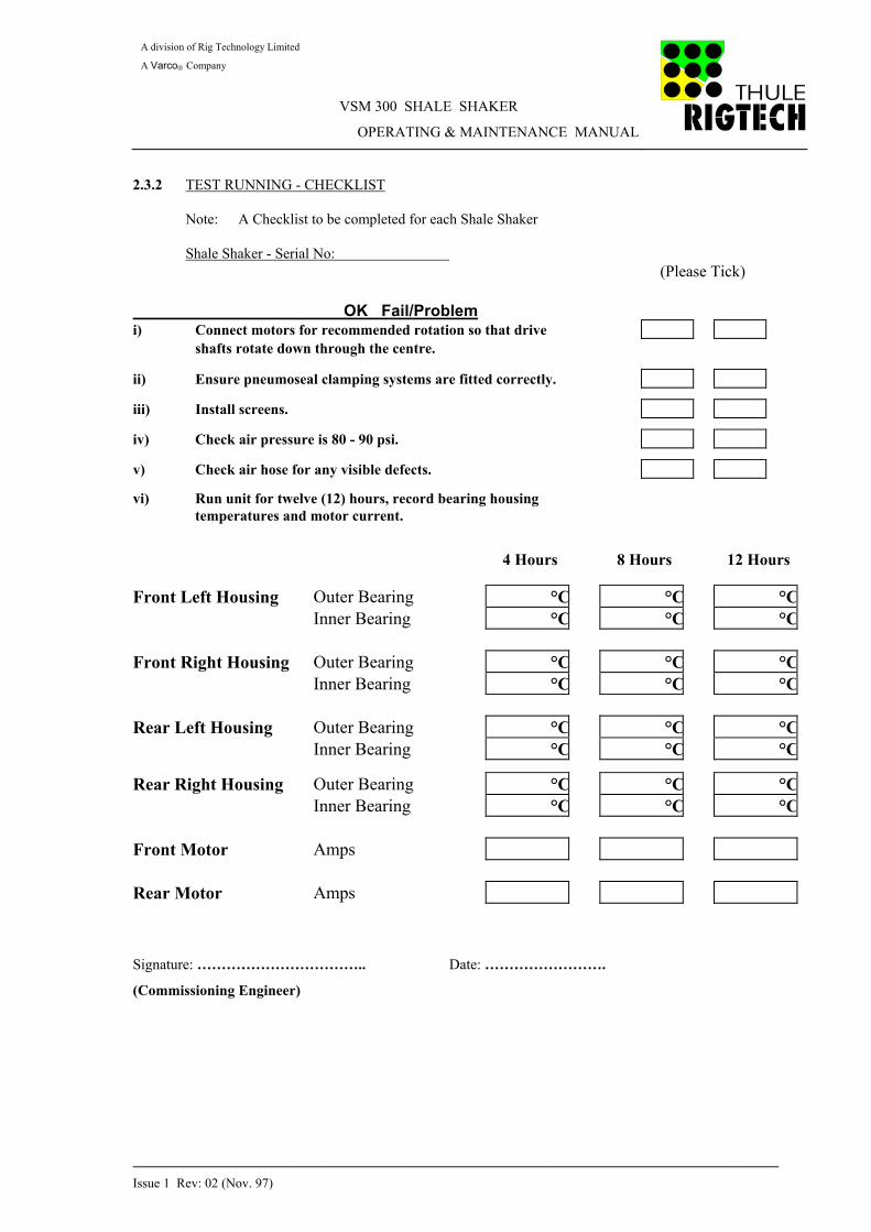
2.3.2 TEST RUNNING - CHECKLIST Note: A Checklist to be completed for each Shale Shaker Shale Shaker - Serial No: (Please Tick)
OK Fail/Problem i) Connect motors for recommended rotation so that drive shafts rotate down through the centre.
ii) Ensure pneumoseal clamping systems are fitted correctly.
iii) Install screens.
iv) Check air pressure is 80 - 90 psi.
v) Check air hose for any visible defects.
vi) Run unit for twelve (12) hours, record bearing housing temperatures and motor current.
4 Hours 8 Hours 12 Hours
Front Left Housing Outer Bearing °C °C °C Inner Bearing °C °C °C Front Right Housing Outer Bearing °C °C °C Inner Bearing °C °C °C Rear Left Housing Outer Bearing °C °C °C Inner Bearing °C °C °C
Rear Right Housing Outer Bearing °C °C °C Inner Bearing °C °C °C Front Motor Amps Rear Motor Amps Signature: …………………………….. Date: …………………….
(Commissioning Engineer)

A division of Rig Technology Limited
A Varco Company
VSM 300 SHALE SHAKER
OPERATING & MAINTENANCE MANUAL
__________________________________________________________________________________________________
Issue 1 Rev: 02 (Nov. 97)
INDEX 3.0 OPERATION 3.1 Functional Description of Equipment
3.2 Health and Safety
3.3 Operating Instructions
1) Start-Up
2) Normal Running
3) Controlled Shutdown
4) Emergency Shutdown 3.4 Screen Data
1) Screen Details
2) Screen Selection
3) Screen Repair Procedure
4) Screen Storage
5) Screen Washing
6) Screen Fitting Procedure
7) Screen Removal Procedure

A division of Rig Technology Limited
A Varco Company
VSM 300 SHALE SHAKER
OPERATING & MAINTENANCE MANUAL
__________________________________________________________________________________________________
Issue 1 Rev: 02 (Nov. 97)
SECTION 3.0 - OPERATION 3.1 FUNCTIONAL DESCRIPTION OF EQUIPMENT
The basic function of the VSM 300 Shale Shaker is to provide primary solids removal from both oil based mud (OBM) and water based mud (WBM) during drilling operations. With the VSM 300, this is achieved by inducing elliptical motion within the shaker basket assembly. The design of the VSM 300 also minimises the operator input required during drilling operations.
3.2 HEALTH AND SAFETY/COSHH STATEMENT
Please refer to Section 2.2.2 of this Manual for Health and Safety information. 3.3 OPERATING INSTRUCTIONS
3.3.1 Start Up
i) Ensure rig air supply is available and pressure regulator is set at 80 - 90 PSI.
ii) Ensure screens are fitted , then set the 3 way ball valve to ‘FEED’ and check pneumoseals are fully inflated.
iii) Ensure isolator is set to ‘ON’ and the reset button has been depressed. Inverter display will show:
iv) Ensure all stop and emergency stop push buttons have been reset.
v) Push start button on remote start/stop station. Inverter display will now show:
DRIVE FREQUENCY 0.0 HZ
DRIVE FREQUENCY 60.0 HZ

A division of Rig Technology Limited
A Varco Company
VSM 300 SHALE SHAKER
OPERATING & MAINTENANCE MANUAL
__________________________________________________________________________________________________
Issue 1 Rev: 02 (Nov. 97)
3.3 OPERATING INSTRUCTIONS (Cont’d)
3.3.1 Start Up (Cont’d)
vi) Open sluice gate on header box/feed chute. vii) Adjust flow until the level of fluid is approximately 10"-15 from the discharge end of
the front primary screen. The fluid level can be adjusted by controlling the volume of fluid entering the feed chute or by careful selection of mesh size.
NOTE: Do not operate the unit with a higher fluid level than recommended. To do
so could result in screen overload and premature screen failure.
3.3.2 Normal Running
When the VSM 300 is running under normal conditions, there are several parameters which can be adjusted to optimise performance - screen size, flow rate and shaker speed.
Screen Size
The selection of screen mesh will depend on a number of factors - namely flowrate, fluid condition, formation, ROP, fluid type and number of shakers. To ensure optimum performance, the finest screen possible should be operated - with due consideration taken of the relative screen life.
Flowrate
Flow should be adjusted to maintain the required beach length. Other preferences such as screen mesh and vibratory speed may also be adjusted to deliver optimised performance.
Shaker Speed
The VSM 300 is designed to operate at 60Hz - both in water and oil based muds. However, a facility is provided to boost the frequency to 67Hz where conditions require i.e. bottoms-up, cold mud etc.

A division of Rig Technology Limited
A Varco Company
VSM 300 SHALE SHAKER
OPERATING & MAINTENANCE MANUAL
__________________________________________________________________________________________________
Issue 1 Rev: 02 (Nov. 97)
3.3 OPERATING INSTRUCTIONS (Cont’d)
3.3.3 Controlled Shutdown
i) Close sluice gate on header box/feed chute. ii) Continue to run unit until mud already on screens has been processed. ii) Thoroughly clean basket/drive assembly and screens using appropriate medium. For
water based muds use steam or high pressure water. For oil based muds use base oil gun.
iv) Push ‘STOP’ push button on the start/stop station. v) Set the 3 way ball valve to ‘VENT’. NOTES:
i) DO NOT turn air supply to vent prior to switching off machine. This can cause
structural damage to the basket assembly and excessive wear to the clamping systems.
ii) If the unit is out of use for long periods, all screens should be removed, cleaned
thoroughly, dried and either re-boxed or stored in a safe dry area. iii) The electrical power supply to the inverter starter should always be left on
unless maintenance is being carried out, even when the shaker is not in use. The temperature will thus be maintained at a level whereby condensation build-up can be avoided.
3.3.4 Emergency Shutdown
In the event of an emergency shutdown being required for whatever reason, the following procedure must be actioned: i) Press emergency button for applicable shaker. ii) Close feed chute gates. Note: At this point there may still be unprocessed drilling fluid within the basket assembly

A division of Rig Technology Limited
A Varco Company
VSM 300 SHALE SHAKER
OPERATING & MAINTENANCE MANUAL
__________________________________________________________________________________________________
Issue 1 Rev: 02 (Nov. 97)
3.3 OPERATING INSTRUCTIONS (Cont’d)
3.3. 4 Emergency Shutdown
iii) Assess the nature of emergency and take appropriate action to rectify/resolve problem. iv) After completion of rectification work and the area is safe, re-start the shaker by
activating the start button on the remote start/stop station. The remaining drilling fluid can now be processed.
NOTE:
Should the problem arise due to power failure, the inverter must be reset as follows:
♦ Set isolator to ‘ON’ ♦ Press reset button
The equipment can now be re-started

A division of Rig Technology Limited
A Varco Company
VSM 300 SHALE SHAKER
OPERATING & MAINTENANCE MANUAL
__________________________________________________________________________________________________
Issue 1 Rev: 02 (Nov. 97)
3.4 SCREEN DATA 3.4.1 Screen Details
VSM 300 Scalping Screens
Mesh Size Aperture Micron Open Area %
8 x 8 2465 60 10 x 10 1976 61 20 x 20 895 49 30 x 30 567 45 40 x 40 399 39 60 x 60 253 36 Special Order Only
80 x 80 186 34 100 x 100 142 31 VSM 300 Pretensioned Screens - Primary
52 x 52 340 48 84 x 84 215 49 105 x 105 165 45 120 x 120 150 49 145 x 145 120 46 165 x 165 105 45 180 x 180 91 42 200 x 200 87 47 230 x 230 75 46 Special Order Only
300 x 300 49 33 325 x 325 42 29
VSM 300 Secondary Screens - Oil Recovery Mode
100H 557 x 184 40 84 x 84 215 49 40 x 80 465 x 148 34 105 x 105 165 45 145 x 145 125 51 165 x 165 104 45 180 x 180 91 42 200 x 200 87 47 230 x 230 75 46

A division of Rig Technology Limited
A Varco Company
VSM 300 SHALE SHAKER
OPERATING & MAINTENANCE MANUAL
__________________________________________________________________________________________________
Issue 1 Rev: 02 (Nov. 97)
3.4 SCREEN DATA (Cont’d) 3.4.2 Screen Selection
Scalping Screens - Upper Deck
The function of the upper deck screen is to remove the large and heavy cuttings only. In general the screen should be selected such that the majority of fluid passes through the first screen. Pre-tensioned Primary Screen - Lower Deck
Pre-tensioned primary screens range in size from 52 - 325 mesh. The mesh should be selected such that during normal operation a beach length of 10 - 15" is maintained. By selecting a mesh which will allow the unit to operate with the correct beach length, a 50% overload capacity is reserved to compensate for changes in mud properties, rig motion and drilled solids.
Secondary Screens (Drying Module)
Secondary screens are designed to reduce the fluid content on solids discharged from the primary screens. These screens are normally used with oil based muds, but are equally suitable with water based muds if required.
Additional fluid is recovered from the solids by the secondary screens in conjunction with the drying bar, allowing the solids to rotate on the mesh before being discharged.
3.4.3 Screen Repair Procedure
i) Carefully clean screen from front and rear.
ii) Using sharp knife (i.e. Stanley Knife), cut torn fine mesh screen from the panel. Cut carefully around the rectangle, ensuring there is no damage to the backing mesh.
iii) Carefully dry the backing mesh with a cloth. This will ensure the repair compound
bonds properly. iv) Lay the screen flat if possible. Using the supplied applicator gun, apply a small amount
of the repair compound to the damaged panel.

A division of Rig Technology Limited
A Varco Company
VSM 300 SHALE SHAKER
OPERATING & MAINTENANCE MANUAL
__________________________________________________________________________________________________
Issue 1 Rev: 02 (Nov. 97)
3.4 SCREEN DATA (Cont’d) 3.4.3 Screen Repair Procedure (Cont’d)
v) Using the plastic spreader, spread the compound, ensuring the backing mesh is fully blanked off. This will ensure that no mud or solids pass through this part of the screen.
vi) Do not apply compound too thickly as this would cause the solids to be stopped on this
panel. Ensure also that the compound is applied over the original grey plastic around the damaged panel to give more strength to the repair.
vii) Stand the screen aside and allow the repair to dry for 4-5 hours. viii) Only use screens which have less than 25% damage. ix) Do not use screens which have buckled edges as these will be sharp and may cut the air
clamping system. Such screens should be discarded.
3.4.4 Screen Storage
Screens should be stored in the cardboard containers supplied in a dry environment and out of direct sunlight. Horizontal or vertical stacking is permissible. Care should be taken to avoid mechanical damage. When transporting the screens from rig store to VSM 300 unit, the screens should be kept in their containers to minimise the risk of damage.
Discard Screen if repaired all the way Across
Backing M esh to be Clean & Dry
Overlap Com poundonto Surrounding Panels
A division of Rig Technology Limited
A Varco Company
VSM 300 SHALE SHAKER
OPERATING & MAINTENANCE MANUAL
__________________________________________________________________________________________________
Issue 1 Rev: 02 (Nov. 97)
3.4 SCREEN DATA (Cont’d) 3.4.5 Screen Washing
Before the VSM 300 is shut down, the screens should be washed with the appropriate medium to avoid plugging or blinding of the meshes by dried mud.
3.4.6 Screen Fitting Procedure
All screens on the VSM 300 are held in place by the pneumoseal clamping systems which allow rapid screen changeout. All pneumoseals are connected to a common air supply so that the 3 way ball valve supplied will inflate/deflate all pneumoseals simultaneously. The top deck and primary deck screens are both of pre-tensioned design but have a different orientation therefore are not interchangeable. The primary screens can be distinguished by the male/female joint arrangement. CAUTION: Gloves should be worn when fitting screens NOTE: The shaker should not be run without screens otherwise the clamping system will ‘blow’ out
of its housing when the air is turned on. i) Top Deck - Pretensioned Screens
Set the 3 way ball valve to ‘VENT’.
Insert the first screen along the top deck ‘C’ channel towards the rear of the shaker (there is no front/back orientation to the top deck screen).
Repeat with the second screen.
Insert the third (front) screen until all screens are firmly located.
Set the 3 way ball valve to ‘FEED’.
ii) Lower Deck Screens (Primary)
Set the 3 way ball valve to ‘VENT’
With the female joint facing the operator, insert the rear screen into the primary channel. With the female joint facing the operator, insert the front screen into the primary channel. Set the 3 way ball valve to ‘FEED’.

A division of Rig Technology Limited
A Varco Company
VSM 300 SHALE SHAKER
OPERATING & MAINTENANCE MANUAL
__________________________________________________________________________________________________
Issue 1 Rev: 02 (Nov. 97)
3.4 SCREEN DATA (Cont’d)
3.4.6 Screen Fitting Procedure (Cont’d)
iii) Secondary Screens (Drying Screens)
To be fitted when drilling with low toxicity or synthetic oil based mud.
Set the 3 way ball valve to ‘VENT’. Insert the secondary screen into secondary screen carrier With the drying bars facing the operator, insert the secondary carrier assembly into the secondary channel and ensure it is firmly located. Set the 3 way ball valve to ‘FEED’.
NOTE: On occasions where the facilities of the secondary screens are not
required, the carrier frames can be removed and replaced with the Solids Deflector Plate. (Supplied)
3.4.7 Screen Removal Procedure
Screen removal is the reverse of the Screen Fitting Procedure above. Note: A screen removal bar is supplied to enable access to the rear screens.

A division of Rig Technology Limited
A Varco Company
VSM 300 SHALE SHAKER
OPERATING & MAINTENANCE MANUAL
__________________________________________________________________________________________________
Issue 1 Rev: 02 (Nov. 97)
INDEX 4.0 MAINTENANCE
4.1 Introduction
4.2 Health and Safety 4.3 Routine Maintenance 4.4 6000 Hour Maintenance Schedule
4.5 Mounting Springs 4.6 Parts Replacement Procedure
1) Pneumoseal Clamping System
2) Drive System - Removal
3) Drive System - Refit
4) Torque Setting Chart
5) Nord Lock Information

A division of Rig Technology Limited A Varco Company
VSM 300 SHALE SHAKER
OPERATING & MAINTENANCE MANUAL
________________________________________________________________________________________________________________
___
Issue 1 Rev: 02 (Nov. 97)
SECTION 4.0 - MAINTENANCE
4.1 INTRODUCTION
Before detailing the recommended maintenance procedures, the following statements on machine maintenance and safety are given and should prove useful to the maintenance engineer.
♦ Ensure that power supplies are isolated before commencing work on the unit.
♦ Clean down all parts and the work area prior to commencement of work.
♦ Block up heavy parts before commencing work beneath the unit or parts.
♦ Where heavy lifting is involved always seek assistance.
♦ Remove the primary screens before commencing work on the shaker.
♦ Before restarting the VSM 300 after maintenance, ensure that all tools, old parts, nuts, bolts, washers etc. are removed.
♦ The bearings are designed to run warm and can be used safely up to an operating temperature of 100°C. Normal operating temperature between 65°- 90°C.
♦ DO NOT weld on any part of the basket or head assembly.
♦ All maintenance to be carried out by suitably qualified personnel.
4.2 HEALTH AND SAFETY
Please refer to Section 2.2.2 of this Manual for Health and Safety information.
4.3 ROUTINE MAINTENANCE
The VSM 300 has been designed to minimise downtime by reducing routine maintenance. To prolong equipment life maintenance instructions given in this section must be strictly adhered to at the prescribed intervals.
Daily
i) Visually examine the unit for signs of wear and or damage. Repair/replace as necessary.
ii) Clean the VSM 300, removing solids build-up.
iii) Perform audible check, investigating as necessary.
v) Check air regulator is set at correct pressure (80-90 psi). Adjust if necessary.
vi) Inspect pneumoseal clamping systems and associated fittings for leaks or wear. Replace as necessary.

A division of Rig Technology Limited A Varco Company
VSM 300 SHALE SHAKER
OPERATING & MAINTENANCE MANUAL
________________________________________________________________________________________________________________
___
Issue 1 Rev: 02 (Nov. 97)
4.4 6000 HOUR MAINTENANCE SCHEDULE (Reference Run Hour Meter)
This Checklist should be completed every 6000 hours of shaker run time and kept in maintenance records.
Shaker No: …………………………. Date: …………………………
Hours Run: ………………………… Rig/Location: ……………………………. Visually examine unit for signs of wear/damage. Repair/replace as necessary. Remove any build-up of solids from electrical motors Run machine and perform audible check. Investigate as necessary Check air regulator is set at the correct pressure (80-90 psi). Adjust if necessary. Initiate Shutdown Procedure - Refer to Section 3.3.3 of this manual. Partially disassemble housings to enable access to bearings. Remove used grease, clean bearings and inspect for wear. If visual inspection satisfactory, replenish grease and replace seals in clump weight housings. Note: To attain good bearing life it is essential that the specified grease is used. (Shell Retinax LX2) Inspect the pneumoseal clamping systems and associated fittings for leaks or wear. Replace as necessary. Using touch-up paint, prepare and paint any part of the shaker basket as required.
Mechanics Name: ………………………………..
Signed: …………………………………………

A division of Rig Technology Limited A Varco Company
VSM 300 SHALE SHAKER
OPERATING & MAINTENANCE MANUAL
________________________________________________________________________________________________________________
___
Issue 1 Rev: 02 (Nov. 97)
4.5 MOUNTING SPRINGS Thule Rigtech recommends that the four (4) main mounting springs are replaced on a bi-annual basis.
4.6 PARTS REPLACEMENT PROCEDURE
WARNING : Before commencing any part replacement procedures initiate a controlled shutdown (Refer to Section 3.3.3). Thereafter the isolator should be switched to ‘OFF’ and locked to isolate the power supply.
4.6.1 PNEUMOSEAL CLAMPING SYSTEM Top Deck - Removal i) Initiate shutdown procedure (Refer to Section 3.3.3) ii) Set the 3 way ball valve to ‘VENT’. iii) Remove the top deck screens.
iv) Pull down the pneumoseal at the air connector.
v) From above press the pneumoseal poppets down through the screen clamping channel and remove from the shaker.
vi) Ensure the poppet holes in the channels are clear of debris, solids, cement etc. Top Deck -Replacement i) Spray poppets on the new pneumoseal with a light oil: e.g. WD40.
ii) Slide the pneumoseal into the channel, lining up the poppets with the holes in the clamping channels.
iii) Starting at the rear, engage poppets into the holes in the clamping channel. Check that
each poppet is properly located. iv) Push the air connector up into its locator on the clamping channel. v) Replace screens. vi) Set 3 way ball valve to ‘FEED’.

A division of Rig Technology Limited A Varco Company
VSM 300 SHALE SHAKER
OPERATING & MAINTENANCE MANUAL
________________________________________________________________________________________________________________
___
Issue 1 Rev: 02 (Nov. 97)
4.6.1 PNEUMOSEAL CLAMPING SYSTEM (Cont’d) Primary Deck - Removal i) Initiate shutdown procedure (Refer to Section 3.3.3) ii) Set the 3 way ball valve to ‘VENT’. iii) Remove the primary screens.
iv) Pull down the pneumoseal at the air connector.
v) Push each poppet on the side rail down through the screen clamping channel and pull forward the rear poppets to release them. Carefully withdraw the pneumoseal from the screen clamping rails.
vi) Ensure the poppet slot/holes in the channels are clear of debris, solids, cement etc.
Note: Rear poppet locators are slotted.
Primary Deck Replacement i) Spray poppets on the new pneumoseal with a light oil: e.g. WD40.
ii) Slide the pneumoseal into the basket - lining up the poppets with slots in the rear channel.
iii) Starting at the rear, engage poppets into the holes in the clamping channel. Check that
each poppet is properly located. iv) Push the air connector up into its locator on the clamping channel. v) Replace the primary screens. vi) Set the 3 way ball valve to ‘FEED’.

A division of Rig Technology Limited A Varco Company
VSM 300 SHALE SHAKER
OPERATING & MAINTENANCE MANUAL
________________________________________________________________________________________________________________
___
Issue 1 Rev: 02 (Nov. 97)
4.6.1 PNEUMOSEAL CLAMPING SYSTEM (Cont’d) Secondary Screen Carrier Removal i) Initiate shutdown procedure (Refer to Section 3.3.3) ii) Set the 3 way ball valve to ‘VENT’. iii) Remove the secondary screen and secondary screen carrier arrangement.
iv) Pull down the pneumoseal at the air connector. v) From above, press the poppet down though the screen clamping channel and remove
from the shaker.
Secondary Screen Carrier Replacement i) Spray poppets on the new pneumoseal with a light oil: e.g. WD40.
ii) Slide the pneumoseal into channel and push the air connector up into its locator. iii) Press poppet into the hole in the channel. iv) Replace secondary screen carrier arrangement.
v) Set the 3 way ball valve to ‘FEED’.
Pneumoseal Air Connectors
i) The pneumoseal air connectors fitted in the shaker basket can be replaced if necessary. ii) The air connectors are removed with a 10mm alley key.

A division of Rig Technology Limited A Varco Company
VSM 300 SHALE SHAKER
OPERATING & MAINTENANCE MANUAL
________________________________________________________________________________________________________________
___
Issue 1 Rev: 02 (Nov. 97)
4.6.2 DRIVE SYSTEM - REMOVAL Drive Shaft Guards i) Remove the top stainless cover four (4) M12 socket cap screws.
ii) Slacken off the tyre coupling taper lock bushings (4 x 5mm grub screws).
iii) To remove the lower guard section use a 10mm hex bar (65mm long) and 10mm ring or ratchet spanner, remove the four (4) M12 socket cap screws.
iv) Repeat this process for all four drive guards.
Clump Weight Housing Removal i) Remove the drive guards as detailed above. ii) Remove four (4) M20 bolts.
iii) Lift the housing from the shaker by means of a fabric strop through lifting eyes which can be inserted into the bearing end plate jacking points.
iv) Repeat this with all the clump weight housings. Clump Weight Housing Disassembly
i) Remove six (6) M12 socket cap screws from the baseplate/access cover and remove. ii) Remove V ring seal from shaft. iii) Remove six (6) M12 socket cap screws from the end caps (both ends). iv) Use three (3) M12 socket cap screws to jack off end caps (both ends). v) Remove the circlips from both ends of the shaft.
vi) Turn the housing upside down to allow access to the clump weight and slacken the two (2) M12 hex head screws clamping the weight to the shaft.
vii) Using a screwdriver prise the clamping sections of the weight open to allow the weight to
slide along the shaft.

A division of Rig Technology Limited A Varco Company
VSM 300 SHALE SHAKER
OPERATING & MAINTENANCE MANUAL
________________________________________________________________________________________________________________
___
Issue 1 Rev: 02 (Nov. 97)
4.6.2 DRIVE SYSTEM - REMOVAL (Cont’d) Clump Weight Housing Disassembly (Cont’d)
viii) Attach disassembly flange to the housing in place of the non-drive end cap with four (4) M12 screws and screw in the centre bolt to displace the shaft.
Note: As the shaft is being displaced it is necessary to have the housing sitting upside down so
that the weight key way can locate the slide through the notch cut in the housing. It is also necessary to slide the weight along the shaft as the shaft is being displaced.
ix) Once the shaft has been removed from the housing the inner bearing race can be taken
off the shaft using three legged pullers. x) The outer bearing races can be jacked out of the housing from the inside using two (2)
M8 70mm bolts.
Clump Weight Housing Assembly
i) For ease of fitment of the non-drive bearing inner race, use a hot plate or similar to warm prior to fitting shaft. Fit circlip.
ii) Refit both bearing outer rings (Use end caps if required to locate). iii) With end caps removed, offer shaft assembly through the clump weight and housing. iv) Fit opposite bearing inner ring. (Inner ring locating tool supplied) Fit circlip. v) To ensure the electric motor will not overload, the bearings should not be overcharged
with grease.
To grease each bearing, use a spatula to manually pack the race from the outer face. After ensuring the bearing is fully packed, half fill the void in the end cap prior to refitting. Note: Both end caps should be oriented: one tapped hole top to ensure correct
alignment with drive guards.
A division of Rig Technology Limited A Varco Company
VSM 300 SHALE SHAKER
OPERATING & MAINTENANCE MANUAL
________________________________________________________________________________________________________________
___
Issue 1 Rev: 02 (Nov. 97)
4.6.2 DRIVE SYSTEM - REMOVAL (Cont’d) Electric Motor i) Remove the drive guards as detailed above. ii) Remove four (4) M16 bolts. iii) Lift the motor by means of a fabric strop through the motor lifting bolt.
iv) To remove the electric motor support plates, remove the two (2) M12 socket cap screws
per plate. v) Repeat for both motors. 4.6.3 DRIVE SYSTEM - REFIT Refit of the drive system is the reverse of removal with the following important checks:
i) Note: Clump weight alignment is essential to enable the VSM 300 to function correctly
ii) To ensure correct clump weight alignment, slacken the tyre couplings to allow both weights to self align by gravity.
iii) This is an essential requirement as the keyways in the motor shafts may not be in direct
alignment iv) Once weight alignment has been achieved, secure tyre couplings.
v) Check drive rotation and replace the guards before operating. (Re: Start-up 3.3.1).
4.6.4 TORQUE SETTING CHART
All bolts and threads on the equipment are of metric sizes and constructed from high tensile stainless steel (U.O.N.)
M8 - 34 Nm ( 25 lbf.ft) M10 - 68 Nm ( 50 lbf.ft) M12 - 118 Nm ( 87 lbf.ft) M16 - 293 Nm (216 lbf.ft) M20 - 570 Nm (420 lbf.ft)
3/16” BSW (Taperlock Grub Screw) - 20 Nm ( 15 lbf.ft) 7/16” BSW (Taperlock Grub Screw) - 30 Nm ( 22 lbf.ft)

A division of Rig Technology Limited A Varco Company
VSM 300 SHALE SHAKER
OPERATING & MAINTENANCE MANUAL
________________________________________________________________________________________________________________
___
Issue 1 Rev: 02 (Nov. 97)
4.6.5 NORD LOCK INFORMATION
All bolts on the VSM 300 are held in place using ‘NORD LOCK’ vibration proof washers. It is very important that the washers are used in the correct orientation for the system to work. The large cams locate together with the fine teeth cutting into the workpiece and bolt / nut. The pair of washers expand more than the corresponding pitch of the thread locking the nut in place.

A division of Rig Technology Limited A Varco Company
VSM 300 SHALE SHAKER
OPERATING & MAINTENANCE MANUAL
________________________________________________________________________________________________________________
___
Issue 1 Rev: 02 (Nov. 97)
INDEX 5.0 PARTS DATA
5.1 Parts List 5.2 Cross Sectional Drawings

A division of Rig Technology Limited A Varco Company
VSM 300 SHALE SHAKER
OPERATING & MAINTENANCE MANUAL
___________________________________________________________________________________________________________________
Issue 1 Rev: 02 (Nov. 97) SECTION 5.0 Page 1 of 6
SECTION 5.1 - PARTS LIST
CLUMP WEIGHT HOUSING ASSEMBLY
Parts List Item Qty per Part Drwg No: No: Description: Shaker: Number: 314-010 1a Clump Weight Housing Assy (Primary) 2 300/01/001a 314-010 1b Clump Weight Housing Assy (Secondary) 2 300/01/001b 314-010 2 Housing Fabrication 4 300/01/002 314-010 3 End Cap 4 300/01/003 314-010 4 Seal Housing 4 300/01/004 314-010 5 Shaft 4 300/01/005 314-010 6 Clump Weight Key 4 300/01/006 314-010 7 Motor Coupling Key 4 300/01/007 314-010 8 Access Cover 4 300/01/008 314-010 9 Primary Clump Weight 4 300/01/009 314-010 10 Secondary Clump Weight 4 300/01/010 314-010 11 Roller Bearing 8 300/01/011 314-010 12 Shaft Seal 4 300/01/012 314-010 13 O-Ring 8 300/01/013 314-010 14 External Circlip 8 300/01/014 314-010 15 V-Ring Seal 4 300/01/015 314-010 16 Plug 8 300/01/016 314-010 24 Clump Weight Housing Spacer 8 300//01/032 314-010 25 Csk Set Screw M8 x 45 16 SSCSK M8x45 314-010 17 Socket Head Cap Screw -M12 x 25 lg 48 SSSKT M12x25 314-010 18 Socket Head Cap Screw - M12 x 20 lg 24 SSSKT M12x20 314-010 19 Hex Head Screw - M12 x 40 lg 8 SSHHS M12x40 314-010 20 Nord-lock Washer - M12 80 pairs SSNLW M12 314-010 21 Hex Head Bolt - M20 x 110 lg 16 SSHHBM20x110 314-010 22 Hex Nut - M20 16 SSPLN M20 314-010 23 Nord-lock Washer - M20 32 pairs SSNLW M20

A division of Rig Technology Limited A Varco Company
VSM 300 SHALE SHAKER
OPERATING & MAINTENANCE MANUAL
___________________________________________________________________________________________________________________
Issue 1 Rev: 02 (Nov. 97) SECTION 5.0 Page 2 of 6
SECTION 5.1 - PARTS LIST (Cont’d)
MOTOR / ASSEMBLIES
Parts List Item Qty per Part Drwg No: No: Description: Shaker: Number: 314-011 16 Electric Motor 2 300/01/017 314-011 17 Electric Motor Shaft Key 4 300/01/031 314-011 7 Motor Shaft Coupling Assembly 4 300/01/018 314-014 1 Coupling Flange 8 300/01/019 314-014 2 Coupling Tyre 4 300/01/020 314-014 3 Taperlock Bush 8 300/01/021 314-014 4 3-Bolt Tab Washer 8 300/01/026 314-014 5 2-Bolt Tab Washer 8 300/01/027 314-014 6 Insert 40 300/01/028 314-014 7 Hex Head Bolt - M6 x 40 lg 40 SSHHB M6x40 314-011 2 Motor Coupling Guard Assembly 4 300/01/022 314-011 3 Coupling Guard 4 300/01/023 314-011 4 Socket Head Cap Screws - M12x20 lg 48 SSSKT M12x20 314-011 5 Nord-lock Washer - M12 48 pairs SSNLW M12
Motor Mounting Plate Assy. 4 300/01/024 314-011 8 Motor Mounting Plate 4 300/01/025 314-011 13 Hex Head Screw - M16 x 50 lg 8 SSHHS M16x50 314-011 15 Hex Nut - M16 8 SSPLN M16 314-011 14 Nord-lock Washer - M16 16 pairs SSNLW M16 314-011 4 Socket Head Screw - M12 x 20 lg 48 SSSKT M12x20 314-011 5 Nord-lock Washer - M12 48 pairs SSNLW M12 314-011 9 Motor Packing Plate 4 300/01/030 314-011 6 Csk Screws - M8 x 16 lg 16 SSCSK M8x16

A division of Rig Technology Limited A Varco Company
VSM 300 SHALE SHAKER
OPERATING & MAINTENANCE MANUAL
___________________________________________________________________________________________________________________
Issue 1 Rev: 02 (Nov. 97) SECTION 5.0 Page 3 of 6
SECTION 5.1 - PARTS LIST (Cont’d)
BASKET FABRICATION Parts List Item Qty per Part Drwg No: No: Description: Shaker: Number: 314-018 Basket Assembly 1 300/02/001 314-018 17 Primary Screen Rear Seal Bar 2 300/02/014 314-018 18 Seal Bar Viton Strip 2 300/02/015 314-018 20 Socket Head Screw - M8 x 30 lg. 10 SSSKT M8x30 314-018 21 Nord-lock Washer - M16 10 pairs SSNLW M8 314-018 19 Csk Screws - M6 x 15 lg 12 SSCSK M6x15
314-018 8 Front Spring Mounting Bracket Assembly 2 300/02/002 314-018 9 Front Spring Mounting Bracket 2 300/02/003 314-018 10 Hex Head Screw - M16 x 40 lg. 8 SSHHS M16x40 314-018 11 Nord-lock Washer - M16 8 pairs SSNLW M16
314-018 12 Rear Spring Mounting Bracket Assembly 2 300/02/004 314-018 13 Rear Spring Mounting Bracket 2 300/02/005 314-018 14 Hex Head Screw - M16 x 40 lg. 8 SSHHS M16x40 314-018 15 Nord-lock Washer - M16 16 pairs SSNLW M16 314-018 16 Hex Nut 8 SSPLM M16
314-018 7 Front Deflector Plate 2 300/02/006
314-018 1 Secondary Screen Carrier Assembly 2 300/02/007 314-018 2 Weir Bar 2 300/02/016 314-018 3 Socket Head Screw - M12 x 25 lg. 10 SSSKT M12x25 314-018 4 Nord-lock Washer - M12 10 pairs SSNLW M12 314-018 5 Plain Washer - M12 10 SSPLW M12 314-018 6 Hex Nut - M12 10 SSPLN M12
314-004 1 Top Screen Pneumoseal 2 300/02/008
314-004 2 Primary Screen Pneumoseal 2 300/02/009
314-004 3 Secondary Screen Pneumoseal 4 300/02/010
314-004 4 Air Connector ‘O’ Ring 8 300/02/011 314-004 5 Air Connection Receptacle 8 300/02/012 314-004 6 Air Receptacle ‘O’ Ring 8 300/02/013

A division of Rig Technology Limited A Varco Company
VSM 300 SHALE SHAKER
OPERATING & MAINTENANCE MANUAL
___________________________________________________________________________________________________________________
Issue 1 Rev: 02 (Nov. 97) SECTION 5.0 Page 4 of 6
SECTION 5.1 - PARTS LIST (Cont’d)
INVERTER
Parts List Item Qty per Part Drwg No: No: Description: Shaker: Number: 300-013 Inverter Assembly 1 300-013 1 Inverter Enclosure 1 300/03/001 300-013 2 Inverter 7.5 kW 1 300/03/002 300-013 3 Filter 1 300/03/003 300-013 4 Thermistor Relay 2 300/03/004 300-013 5 Contactor 7.5 kW 5 300/03/005 300-013 6 Overload Relay 6 - 9A 2 300/03/006 300-013 7 Transformer 1 300/03/036 300-013 8 Relay 2 300/03/037 300-013 9 Primary Fuse Holder 2 300/03/009 300-013 10 Primary Fuse 2 300/03/010 300-013 11 Secondary Fuse Holder 1 300/03/011 300-013 12 Secondary Fuse 1 300/03/012 300-013 11 Neutral Link Holder 1 300/03/011 300-013 13 Neutral Link 1 300/03/013 300-013 14 Ammeter 2 300/03/014 300-013 15 Hours Run Meter 1 300/03/015 300-013 16 Reset Pushbutton 1 300/03/016 300-013 17 Terminal 17 300/03/017 300-013 18 Fault Indicator Light ( Red) 2 300/03/018 300-013 19 Terminal 3 300/03/034 300-013 20 Terminal 3 300/03/035

A division of Rig Technology Limited A Varco Company
VSM 300 SHALE SHAKER
OPERATING & MAINTENANCE MANUAL
___________________________________________________________________________________________________________________
Issue 1 Rev: 02 (Nov. 97) SECTION 5.0 Page 5 of 6
SECTION 5.1 - PARTS LIST (Cont’d)
ASSOCIATED ELECTRICAL EQUIPMENT
Qty per Description: Shaker Part No:
Isolator 1 300/03/019 Stop/Start Station 1 300/03/020 Emergency Stop Station 1 300/03/021 Gland - M20 Barrier Exd 2 300/03/024
Gland - M25 Barrier Exd 4 300/03/038 Gland - M20 Double Compression Exd/Exe 10 300/03/039
Shroud - M20 2 300/03/025 Shroud - M25 4 300/03/040 Exd Plug - M20 7 300/03/026 Exd Plug - M25 4 300/03/027 Exd Adaptor - M20 Male x M25 Female 3 300/03/041 Locknut - M20 2 300/03/042 Lockwasher - M20 2 300/03/043
Earth Strap 3 300/03/023 Earth Tag - M20 12 300/03/028 Earth Tag - M25 4 300/03/044 Fibre Washer - M20 12 300/03/029
Fibre Washer - M25 4 300/03/045 Pan Head Set Screw Assy - M6 x 25 lg. 4 SSPHS M6x25 Pan Head Set Screw Assy - M4 x 25 lg. 6 SSPHS M4x25
A.C. Supply Choke 1 300/03/030 A.C. Supply Choke Enclosure * 1 300/03/031 3 Button Speed Control Station 1 300/03/032 * Note: Enclosure sized to suit number of Shakers per installation

A division of Rig Technology Limited A Varco Company
VSM 300 SHALE SHAKER
OPERATING & MAINTENANCE MANUAL
___________________________________________________________________________________________________________________
Issue 1 Rev: 02 (Nov. 97) SECTION 5.0 Page 6 of 6
SECTION 5.1 - PARTS LIST (Cont’d)
PNEUMATIC ASSEMBLY
Parts List Item Qty per Part Drwg No: No: Description: Shaker: Number: 314-015 1 Pneumatic Control Panel Assembly 1 300/04/001 314-015 2 Mounting Plate c/w Bolts 1 300/04/002 314-015 3 Air Regulator 1 300/04/003 314-015 4 Pressure Gauge : 0 - 100 PSI 1 300/04/004 314-015 5 3 Way Valve 1 300/04/005 314-015 6 Non-Return Valve 1 300/04/006 314-015 7 Adaptor - No. 6 JIC x ¼” NPT 3 300/04/007 314-015 8 90o Swivel Elbow No. 6 JIC 3 300/04/008 314-105 9 Swivel Hosetail No. 6 JIC 3 300/04/009 314-015 10 Hose Clips 6 300/04/010 314-015 11 Air Hose 30m 300/04/011
VSM 300 RETROFIT KIT
Sump Adaptor Bracket Assembly 2 300/05/002 VSM 300 Feedchute 1 300/05/003 Mounting Spring 4 300/05/004 Mounting Spring Pad 8 300/05/005
MAINTENANCE EQUIPMENT
Screen Repair Applicator 1 300/06/001 Screen Repair Compound (380ml) 1 300/06/002 Main Bearing Grease (400g) 1 300/06/003

A division of Rig Technology Limited
A Varco Company
VSM 300 SHALE SHAKER
OPERATING & MAINTENANCE MANUAL
___________________________________________________________________________________________________
Issue 1 Rev: 02 (Nov. 97)
SECTION 5.2 - CROSS SECTIONAL DRAWINGS
INDEX
314-004 Clamping System Arrangement 314-010 Clump Weight Housing Assembly 314-011 Vibratory Drive Assembly 314-013 Inverter Enclosure General Arrangement 314-014 Motor Shaft Coupling Assembly 314-015 Pneumatic Control Panel 314-018 Basket Assembly

A division of Rig Technology Limited
A Varco Company
VSM 300 SHALE SHAKER
OPERATING & MAINTENANCE MANUAL
___________________________________________________________________________________________________
Issue 1 Rev: 02 (Nov. 97)
INDEX 6.0 FAULT FINDING
6.1 Fault Finding/Correction Checklist

A division of Rig Technology Limited A Varco Company
_____________________________________________________________________________________________________________
Issue 1 Rev: 02 (Nov. 97)
SECTION 6.1 - FAULT FINDING/CORRECTION CHECKLIST
Symptom: Probable Cause: Remedial Action:
Electrical: i) Both motors fail to rotate Main supply down Check supply to inverter enclosure Inverter should read Drive Frequency
0.0Hz Check isolator is in ‘ON’ position Check fuses Check reset button is depressed
ii) One motor fails to rotate Broken wires to motor(s) Check wiring iii) One motor fails after Electric motor faulty Check/change motor
start-up Excessive grease in main Remove excess grease (Fault light showing) shaft bearings Thermal overload setting Reset overload to correct setting Thermister relay tripped Check wiring inside terminal box to thermister terminals
iv) Shaker stops (No fault Inverter trips Check fault finding section of light showing) Inverter Manual (See Section 9.0)
Mechanical: i) Both drive shafts fail to
rotate Bearing failure Replace bearings
ii) One drive shaft fails to rotate
Bearing failure Replace bearings
iii) Bearing failure Wrong grease Use recommended grease - Section 6.0 Grease system/
seal failure Check grease passage
iv) Motor running with Tyre coupling failure Replace tyre coupling no vibration/unusual
vibration Check weights set in line.
v) Pneumatic clamping failure
Incorrect pressure Check air supply and pressure is correct (80-90 psi)
Incorrectly fitted screens Check screens are properly located Incorrectly fitted air
connector Check air connection

A division of Rig Technology Limited A Varco Company
_____________________________________________________________________________________________________________
Issue 1 Rev: 02 (Nov. 97)
SECTION 6.1 - FAULT FINDING/CORRECTION CHECKLIST
Symptom: Probable Cause: Remedial Action:
vi) Solids transportation Shaft rotation Check shaft rotation limited Damaged screen Replace screen Angle of basket Operate unit in horizontal position only Spray bars off (WBM) Use spray bars
vii) Short screen life Screen too fine Change to coarser screen Premature damage Check storage and handling Angle of basket Check basket is operated in horizontal
position Inadequate washdown
facilities High pressure clean with appropriate fluid
Incorrect fluid level Adjust to 10-15” beach (OBM)
viii) Excessive noise Loose bolts Check torque on all bolted assys. Pneumatic clamping system Check pressure Bearing failure Replace bearings
ix) Unusual vibrations Weakened mounting spring Change mounting spring Incorrect shaft rotation Check directions
Additional Recommendations for Water Based Drilling Fluids
Symptom: Remedial Action: i) Lack of bottom Fit finer primary screens and ensure beach length is 6-8” screen transportation Rotate screens, allowing one set to be used as back-up Clean back-up screens from rear with high pressure wash gun Ensure adequate washdown facilities are available (ie high pressure wash gun) Install spray bar system (Contact Thule Rigtech)
ii) Lack of top transportation
Remove front gate in distribution chute and allow fluid to wash over onto screen.

A division of Rig Technology Limited A Varco Company
_____________________________________________________________________________________________________________
Issue 1 Rev: 02 (Nov. 97)
INDEX 7.0 DRAWINGS
314-001 Basket General Arrangement 314-002 Vibratory Drive General Arrangement 314-003 Vibratory Drive Clump Weight Housing Assy 314-008 VSM 300 Lifting Details 314-009 Shaker Schematic Wiring Diagram (Sheets 1 & 2) 314-012 Shaker Bonding Arrangement
314-016 Shaker Termination Drawing
314-017 Shaker Cable Schedule

A division of Rig Technology Limited A Varco Company
_____________________________________________________________________________________________________________
Issue 1 Rev: 02 (Nov. 97)
INDEX 8.0 SUB VENDOR MANUALS 1) Inverter Manual 2) Thermistor Protection Units

A division of Rig Technology Limited A Varco Company
_____________________________________________________________________________________________________________
Issue 1 Rev: 02 (Nov. 97)
INDEX
9.0 SERVICE BULLETINS