VRV IV - emiratesgbc.orgDaikin VRV IV Variable Refrigerant Temperature control for energy saving in...
36
VRV IV heat pump and water cooled systems VRV IV Sets the Standard... Again High Ambient
Transcript of VRV IV - emiratesgbc.orgDaikin VRV IV Variable Refrigerant Temperature control for energy saving in...

VRV IV heat pump and water cooled systems
VRV IVSets the Standard... Again
High Ambient

ECPEN15-206A.indd 2 24/03/15 11:47
Our new VRV IV systems set pioneering standards in
all-round climate comfort performance.
Total design simplicity, off ering rapid installation, full
fl exibility as well as absolute effi ciency and comfort.
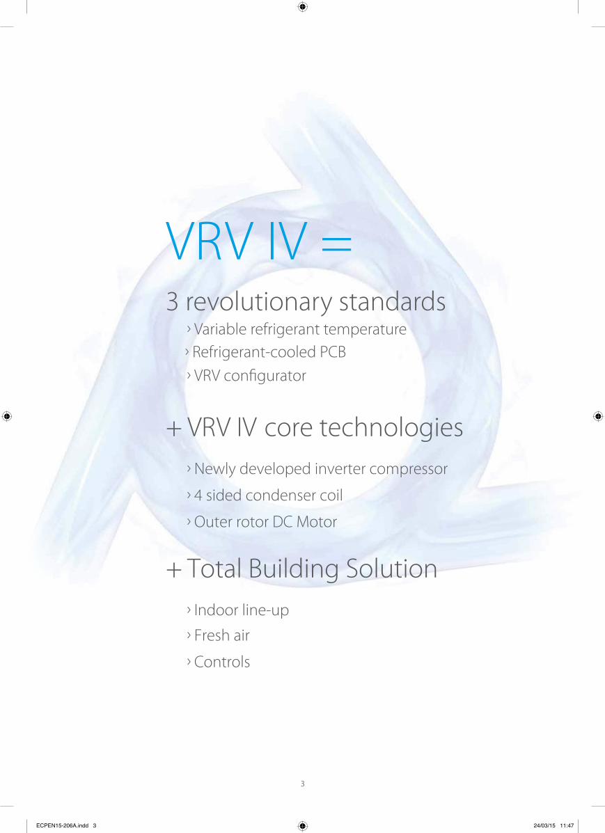
VRV IV =sdradnats yranoitulover 3
Variable refrigerant temperature Refrigerant-cooled PCB
Newly developed inverter compressor
4 sided condenser coil
Outer rotor DC Motor
VRV confi gurator
+ VRV IV core technologies
Indoor line-up
Controls
Fresh air
+ Total Building Solution
ECPEN15-206A.indd 3 24/03/15 11:47

4
Over 30 years of
VRV History
1982 1991 1994 1998 2003 2004 2005
Daikin introduces the VRVII,
the world’s R-410A
operated variable refrigerant
flow system. Available in cooling
only, heat pump and heat recovery
versions. No less than 40 indoor units in heat recovery as well as
heat pump format can be
connected to a single refrigerant
circuit.
Daikin Daikin extends
the operational scope of
its acclaimed VRVII inverter
driven dx air conditioning
system, with a new water cooled version, VRV-WII. Available in both heat pump
and heat recovery versions.
The original VRV air conditioning
system developed by Daikin Industries Ltd. in 1982 is introduced into Europe in VRV
standard format. VRV D series can
supply conditioned air from up to
6 indoor units connected to
a single outdoor unit.
A further step forward
is taken in 1991 with the
introduction of the
VRV heat recovery system,
offering simultaneous cooling
and heating from different
indoor units on the same
refrigeration circuit.
Consistent high quality and
efficiency lead to the wide-
spread acceptance of the VRV
concept and Daikin becomes the
first Japanese air conditioning
manufacturer to be awarded the
ISO9001 certification.
The introduction
of the VRVII-S series extends
the VRV operating scope
into the light commercial sectors. Available in 4, 5 and
6HP capacities, the system is
designed for installation in
up to 9 rooms.In anticipation of phase out dates
for all CFC based equipment,
Daikin Europe launched a VRV
interter series with R-407C.
As many as 16 indoor units can be
connected to 1 single outdoor unit.
ECPEN15-200A.indd 252 24/03/15 11:39

Daikin extends its VRV range
with the innovative replacement
VRV – a highly cost effective
replacement for VRV systems still
operating on the banned
R-22 refrigerant. This cost effective
upgrade is possible because
VRVIII-Q outdoor units can be
installed using existing piping and
in some cases existing indoor units.
The fourth generation
of VRV is launched. The unit sets
new standards in the industry
with 28% better seasonal cy and continuous heating
on heat pumps.
2008 2009 2010 2012 2015
Daikin announces the third
generation of its much acclaimed
VRV range with the extensively
re-engineered VRVIII. Available
in heat recovery, heat pump and
cooling versions, VRVIII incorporates
all the best features of earlier VRV
systems. However, it also possesses
a considerable number of new
design, installation and maintenance
refinements such as automatic charging and testing.
Up to 64 indoor untis
can be connected to
one system.
Daikin introduces a new heat
pump range optimised for
heating (VRVIII-C).
This new range has an
extended operation range down to -25°C and has a
greatly improved COP in low
ambient temperatures, with
the newly developed 2-stage
compressor system.
Daikin extends the VRVIII range
with the water cooled VRV-WIII.
A geothermal version is also
available now.
This system uses geothermal heat
as a renewable energy source
and can operate down to -10°C in
heating mode.
Opt
ions
& A
cces
sorie
s
ECPEN15-200A.indd 253 24/03/15 11:39
5
VRV IV for High Ambient Region

VRF standardCapacity is controlled only with the variance of the inverter compressor
Daikin VRV IVVariable Refrigerant Temperature control for energy saving in partial load condition.The capacity is controlled by the inverter compressor AND variation of the evaporating (Te) and condens-ing (Tc) temperature of the refrigerant in order to achieve the highest seasonal effi ciency.
Variable refrigerant
temperature
Customise your VRV for best seasonal effi ciency and comfortThanks to its revolutionary variable refrigerant temperatue technology (VRT), VRV IV continuously adjusts both the inverter compressor speed and the refrigerant temperature, providing the necessary capacity to meet the building load with the highest seasonal effi ciency at all times!
› Seasonal e ciency increased by 28%› t weather compensating control on the
market› Customer comfort is assured thanks to higher
outblow temperatures (preventing cold draughts)
Refr
iger
ant t
empe
ratu
re in
co
olin
g (e
vapo
ratin
g te
mpe
r-at
ure)
Variable Te
Fixed Te
Outdoor temperature
Effi c
ienc
y
Outdoor temperature
E ciency up
Cap
acity
& L
oad
in c
oolin
g m
ode
Cooling requirement
Design point
Outdoor temperature
Adjust capacity by Te control to meet the load (avoid over capacity and ON/OFF operation)
Syst
em
capa
city
A higher refrigerant temperature results in a higher seasonal e ciency and higher comfort
The lower the capacity need the higher the refrigerant temperature can be
The colder it gets, the lower the load on the building and the lower the capacity need
How does it work?
ECPEN15-206A.indd 4 24/03/15 11:47
25 30 38 46
25 30 38 46
25 30 38 46
6
Variable Temp.
Fixed Temp.
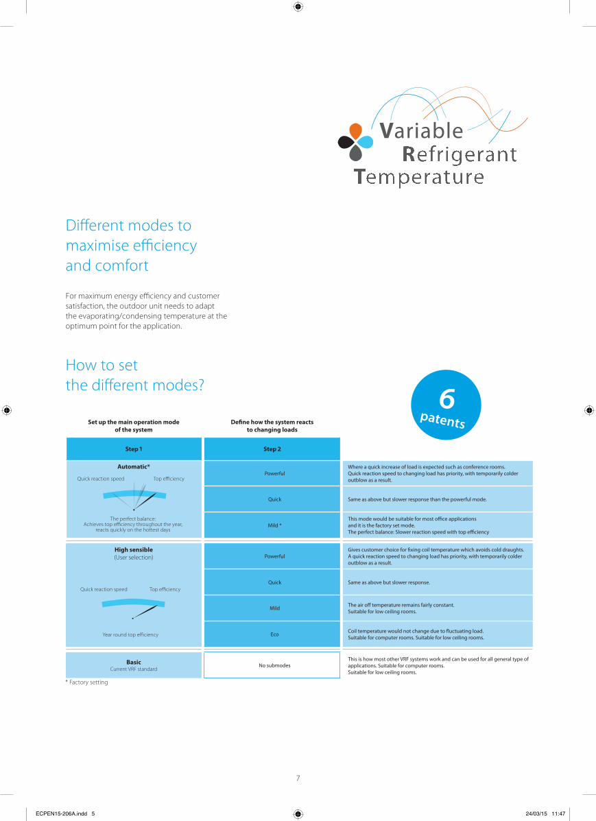
Diff erent modes to maximise effi ciency and comfort
For maximum energy efficiency and customer satisfaction, the outdoor unit needs to adapt the evaporating/condensing temperature at the optimum point for the application.
Set up the main operation mode of the system
Defi ne how the system reacts to changing loads
St St
Automatic*Powerful
Where a quick increase of load is expected such as conference rooms. Quick reaction speed to changing load has priority, with temporarily colder outblow as a result.
Quick Same as above but slower response than the powerful mode.
Mild *This mode would be suitable for most o ce applications and it is the factory set mode.The perfect balance: Slower reaction speed with top e ciency
High sensible(User selection) Powerful
Gives customer choice for fi xing coil temperature which avoids cold draughts. A quick reaction speed to changing load has priority, with temporarily colder outblow as a result.
Quick Same as above but slower response.
Mild The air o temperature remains fairly constant. Suitable for low ceiling rooms.
Eco Coil temperature would not change due to fl uctuating load. Suitable for computer rooms. Suitable for low ceiling rooms.
BasicCurrent VRF standard
No submodesThis is how most other VRF systems work and can be used for all general type of applications. Suitable for computer rooms. Suitable for low ceiling rooms.
The perfect balance: Achieves top effi ciency throughout the year,
reacts quickly on the hottest days
Quick reaction speed Top effi ciency
Year round top effi ciency
Quick reaction speed Top effi ciency
patents
How to setthe diff erent modes?
* Factory setting
ECPEN15-206A.indd 5 24/03/15 11:47
7

Software for simplifi ed commissioning, confi guration and customisation
ECPEN15-206A.indd 8 24/03/15 11:48
8

VRVconfi gurator software
Simplifi ed servicingThe user-friendly display for outdoor units simplifi es basic servicing tasks. Easy-to-read error report Easy-to-understand menu indicates quick and easy on-site settings
Easy-to-follow parameters for checking basic functions: high pressure, low pressure, frequency and operation time, compressor history, temperature of discharge/suction pipe.
Simplifi ed commissioningThe VRV confi gurator is an advanced software solution that allows for easy system confi guration and commissioning. Less time is required on the roof to confi gure the outdoor unit
Multiple systems at diff erent sites can be managed in exactly the same way, providing simplifi ed commissioning for key accounts
Initial settings on the outdoor unit can be easily retrieved
-digit egment display
User-friendly interface instead of push buttons
Graphical interface Manage systems over multiple sites in exactly the same way
Retrieve initial settings
ECPEN15-206A.indd 9 24/03/15 11:48
Connect directly to your laptop
Pre configuredsettings from office
9
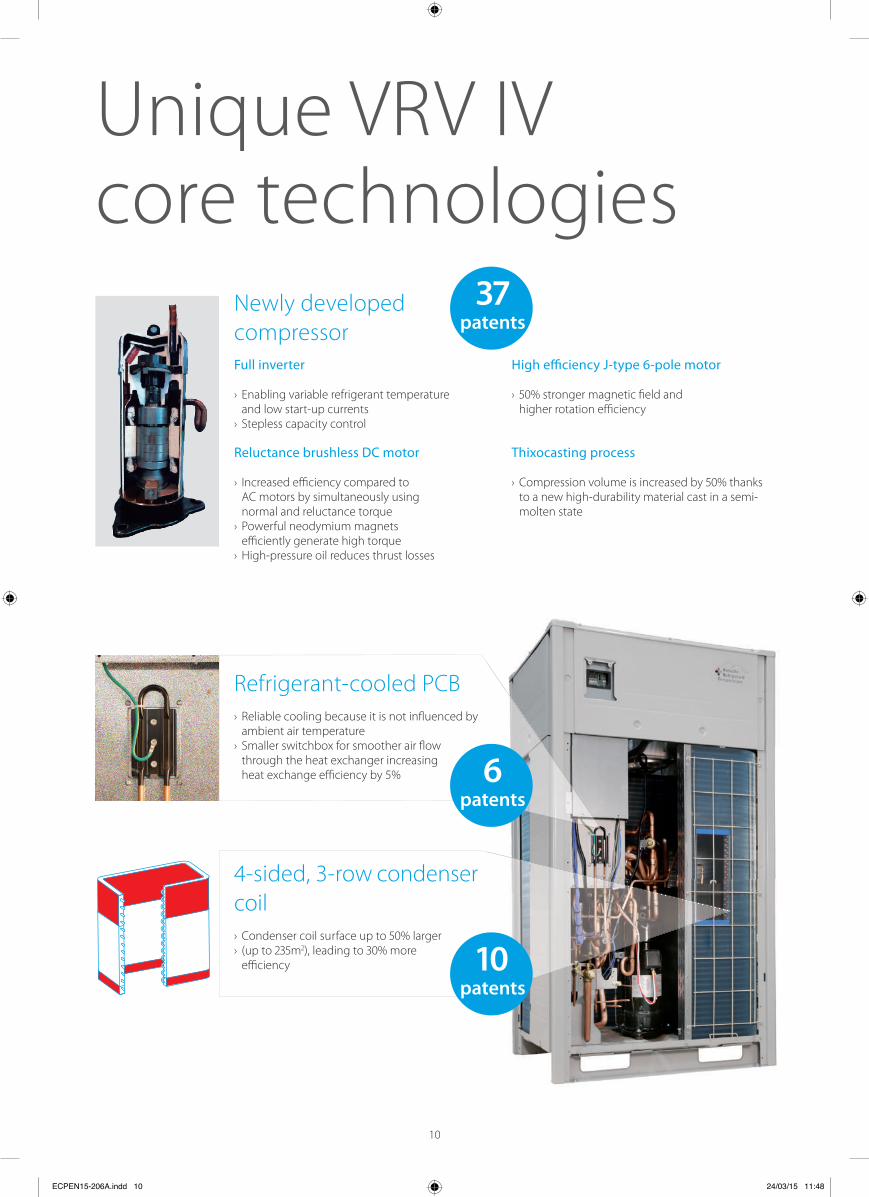
4-sided, 3-row condensercoil› Condenser coil su rface up t rger › (up t ), leading t re
effi ciency
Refrigerant-cooled PCB› Reliable cooling because it is not infl uenced by
ambient air temperature› Smaller switchbox for smoother air fl ow
through the heat exchanger increasingheat exchange effi ciency by 5%
Newly developed compressor Full inverter
› Enabling variable refrigerant temperatureand low start-up currents
› Stepless capacity control
Reluctance brushless DC motor
› Increased effi ciency compared toAC motors by simultaneously usingnormal and reluctance torque
› Powerful neodymium magnetseffi ciently generate high torque
› High-pressure oil reduces thrust losses
High e ciency J-t ole motor
› ronger magnetic fi eld andhigher rotation effi ciency
Thixocasting process
› Compression volume is increased bto a new high-durability material cast in a semi-molten state
Unique VRV IV core technologies
patents
patents
patents
ECPEN15-206A.indd 10 24/03/15 11:48
10

DC fan motor
Outer rotor DC motor for higher e ciency
› Larger rotor diameter results in greaterforce for the same magnetic fi eld,leading to better effi ciency
› Better control, resulting in more fansteps to match the actual capacity
Sine wave DC inverter
Optimizing the sine wave curve results in smoother motor rotation and improved motor effi ciency.
DC fan motor
The use of a DC fan motor off ers substantial improvements in operating effi ciency compared to conventional AC motors, especially during low speed rotation.
E-Pass Heat Exchanger Optimising the heat exchanger’s path layout prevents heat being transferred from the overheated gas section to the sub-cooled liquid section which is a more effi cient way to use the heat exchanger.
Standard heat exchanger
In °C
°C
°C
°C
°C
°C
e-Pass heat exchanger
°C
In °C
°C
°C
°C
°C
Power consumption
Predefi ned limit
Time
I-demand functionLimit maximum power consumption.The newly introduced current sensor minimizes the diff erence between the actual power consumption and the predefi ned power consumption.
Predictive Control Function (PCF)› Reaches the target capacity/refrigerant temperature
faster› Reaches the target without overshooting, so there is
no waste, leading to improved effi ciency› Three capacity settings give more precise control
for user comfort
Target
t(VRV IV)
VRV IV with PCF
General VRF with PI control
Target capacity/refrigerant temperature
t (general VRF)
VRV IV: PCF
Compressor works with predictive data for the control
› result: quick convergence to the target temperature
and reduction of waste operation of the compressor
General VRF: Pi control
Compressor works with feedback only for the control
› result: waste operation and longer time before reaching
target set point
Conventional motor with inner rotor
Rotor RotorStator Stator
Daikin outer rotor
FF
Waste compressor operation
Half timeagainst general
VRF
General VRF:Double time against VRV IV
UNIQUE
UNIQUE
ECPEN15-206A.indd 11 24/03/15 11:48
11
The large number of Daikin systems already in operation and which are monitored by our Intelligent Network software put us in the unique position of being able to analyse this data and develop the predictive compressor control function.
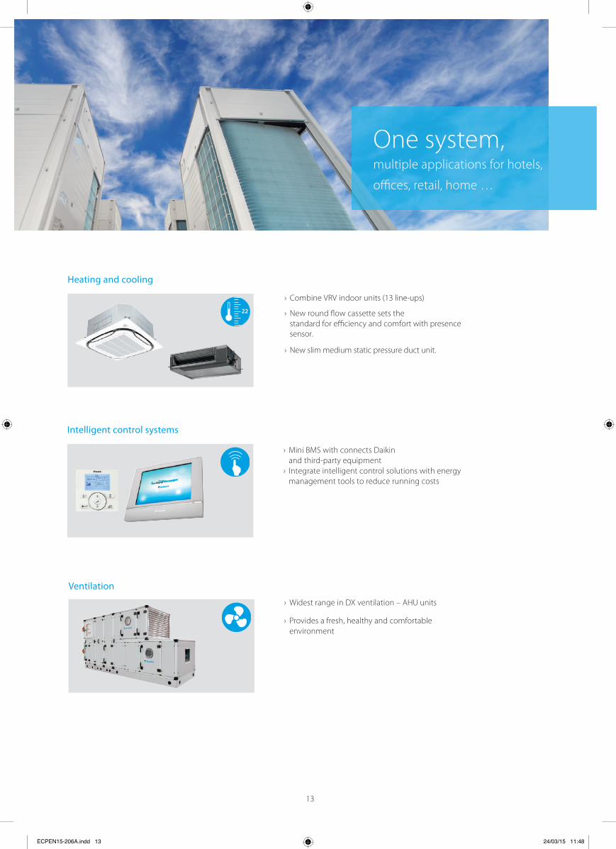
Typically, many buildings today rely on several separate systems for heating, cooling & air curtain As a result energy is wasted. To provide a much more e cient alternative, VRV technology has been
developed into a total solution managing up to of a buildings energy consumption giving large
potential to cost saving.
› Heating and coolingfor year round comfort
› Ventilationfor high quality environments
› Controlsfor maximum operating effi ciency
The total solution
Fresh Air
Heating
Cooling
Controls
Ventilation
12
ECPEN15-206A.indd 12 24/03/15 11:48
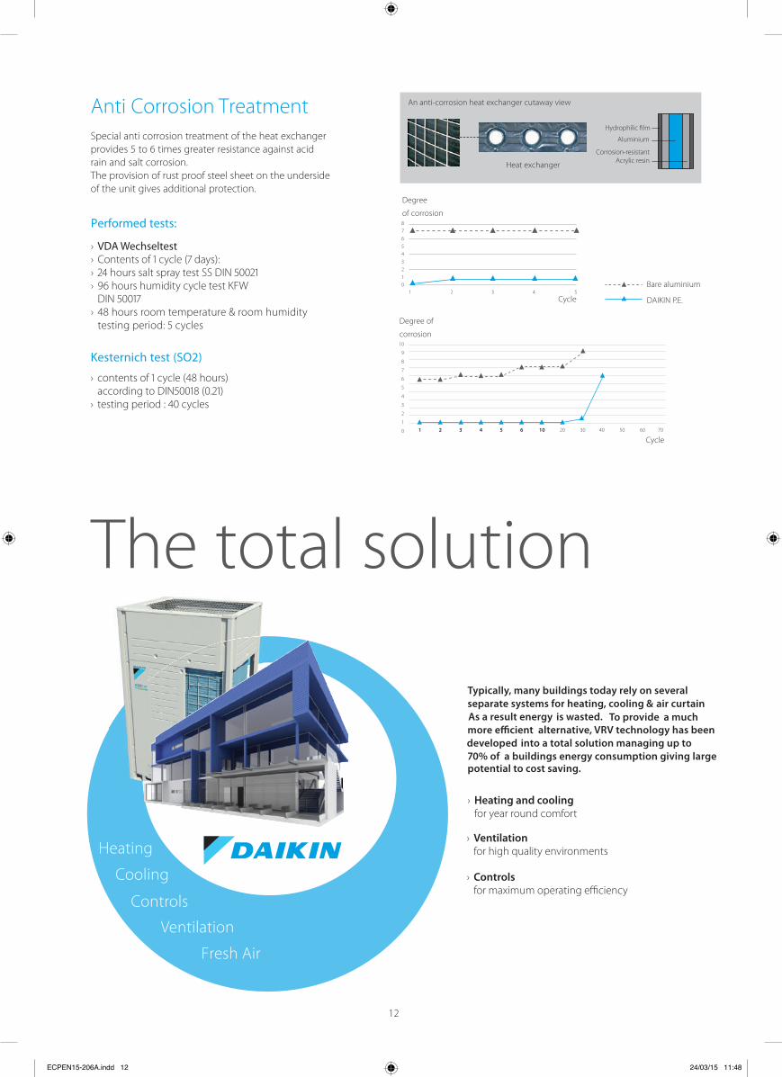
Heat exchanger
An anti-corrosion heat exchanger cutaway view
Aluminium
Hydrophilic film
Corrosion-resistantAcrylic resin
Anti Corrosion TreatmentSpecial anti corrosion treatment of the heat exchanger provides 5 to 6 times greater resistance against acid rain and salt corrosion. The provision of rust proof steel sheet on the underside of the unit gives additional protection.
Performed tests:
› VDA Wechseltest›››
›
Kesternich test (SO2)
›
›
8
7
6
5
4
3
2
1
01 2 3 4 5
Cycle
Cycle
Degree
of corrosion
Degree of
corrosion
DAIKIN P.E.
Bare aluminium
10
9
8
7
6
5
4
3
2
1
0 1 2 3 4 5 6 10 20 30 40 50 60 70
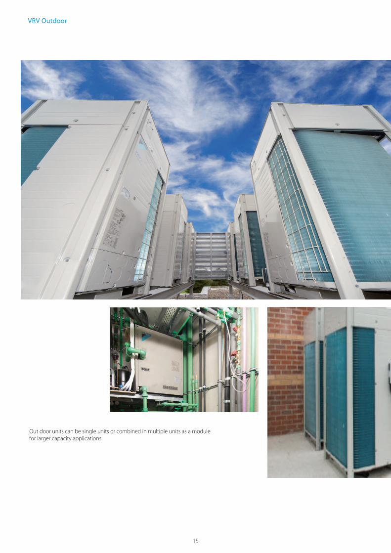
One system, multiple applications for hotels,
offi ces, retail, home …
Heating and cooling
Intelligent control systems
› Combine VRV indoor units (13 line-ups)
› New slim medium static pressure duct unit.
› New round flow cassette sets the standard for efficiency and comfort with presence sensor.
› Mini BMS with connects Daikin and third-party equipment
› Integrate intelligent control solutions with energy management tools to reduce running costs
Ventilation
› Widest range in DX ventilation – AHU units
› Provides a fresh, healthy and comfortable environment
22
ECPEN15-206A.indd 13 24/03/15 11:48
13

ConsultantsDaikin's VRV IV technology maximises fl exibility and leads the way in customisation to match individual building requirements in comfort and energy, with reduced running costs.
E Technical design support
cological design meets and exceeds legal requirements
Maximum fl exibility to meet customer requirements Advanced software tools assist with system design
Building ownersVRV IV is the ultimate in customised comfort and intelligent control tailored to your individual needs and to maximise energy effi ciency. Annual cost savings up to % (compared to VRV III).
Up to 40% energy consumption saving over conventional AC System Single point of contact for the design and maintenance of your climate system
Integrated system, combining air conditioning, ventilation, etc. allows maximum energy effi ciency
Multiple systems can be managed in exactly the same way for the key accounts
Dedicated after-sales service to ensure fast on-site support
InstallersDaikin VRV IV sets the standard with state-of-the-art technology and time-saving commissioning and servicing.
Simplifi ed and time-saving commissioning with VRV confi gurator
Wide range of outdoor units (up to 48HP) One supplier = one point of contact Maximum fl exibility to meet customer requirements Customised training to maximise expertise
14
ECPEN15-206A.indd 18 24/03/15 11:48
Complies with ESMA UAE regulationsComplies with MEW-Kuwait regulationsComplies with SASO Saudi regulations
What does aVRV IV installation mean to you?
See how you can profi t from
Daikin’s highly fl exible and
effi cient product range.
15
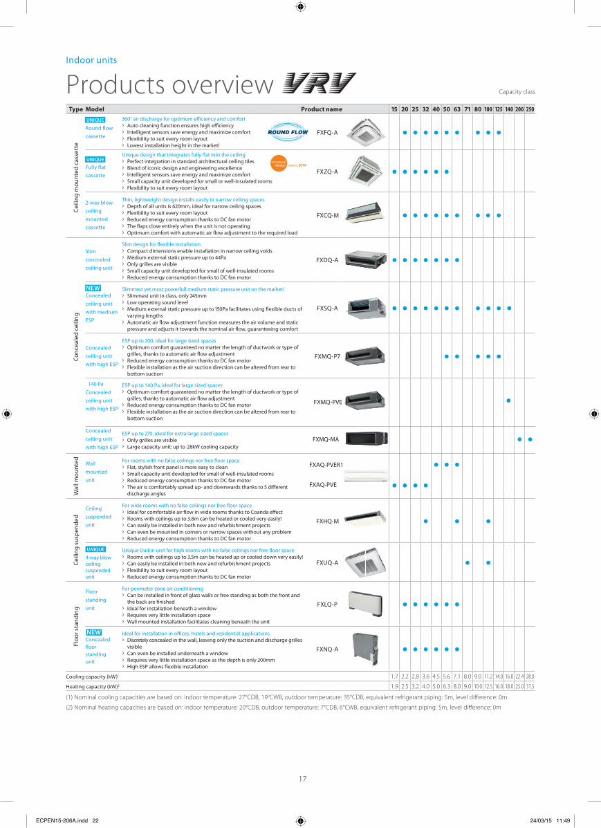
VRV Outdoor
Out door units can be single units or combined in multiple units as a modulefor larger capacity applications

16
P
(50Hz)
(60Hz)
Outdoor units
UNIQUE
UNIQUE
NEW
NEW
(1) Nominal cooling capacities are based on: indoor temperature: 27°CDB, 19°CWB, outdoor temperature: 35°CDB, equivalent refrigerant piping: 5m, level difference: 0m
(2) Nominal heating capacities are based on: indoor temperature: 20°CDB, outdoor temperature: 7°CDB, 6°CWB, equivalent refrigerant piping: 5m, level difference: 0m
Type Model Product name
Ceili
ng m
ount
ed c
asse
tte
Round fl ow cassette
› Auto cleaning function ensures high e ciency› Intelligent sensors save energy and maximize comfort› Flexibility to suit every room layout› Lowest installation height in the market!
FXFQ-A
Fully fl at cassette
Unique design that integrates fully fl at into the ceiling› Perfect integration in standard architectural ceiling tiles› Blend of iconic design and engineering excellence› Intelligent sensors save energy and maximize comfort› Small capacity unit developed for small or well-insulated rooms› Flexibility to suit every room layout
FXZQ-A
ceiling mounted cassette
Thin, lightweight design installs easily in narrow ceiling spaces ›
› Flexibility to suit every room layout› Reduced energy consumption thanks to DC fan motor› The fl aps close entirely when the unit is not operating› Optimum comfort with automatic air fl ow adjustment to the required load
FXCQ-M
Conc
eale
d ce
iling
Slim concealed ceiling unit
Slim design for fl exible installation› Compact dimensions enable installation in narrow ceiling voids›› Only grilles are visible› Small capacity unit developted for small of well-insulated rooms› Reduced energy consumption thanks to DC fan motor
FXDQ-A
Concealed ceiling unit with medium ESP
Slimmest yet most powerfull medium static pressure unit on the market! ›
› Low operating sound level ›
varying lengths› Automatic air fl ow adjustment function measures the air volume and static
pressure and adjusts it towards the nominal air fl ow, guaranteeing comfort
F
FXMQ-PVE
XSQ-A
Concealed ceiling unit with high ESP
› Optimum comfort guaranteed no matter the length of ductwork or type of grilles, thanks to automatic air fl ow adjustment
› Reduced energy consumption thanks to DC fan motor› Flexible installation as the air suction direction can be altered from rear to
bottom suction
Concealed
140 Pa
ceiling unit with high ESP
› Optimum comfort guaranteed no matter the length of ductwork or type of grilles, thanks to automatic air fl ow adjustment
› Reduced energy consumption thanks to DC fan motor› Flexible installation as the air suction direction can be altered from rear to
bottom suction
Concealed ceiling unit with high ESP
› Only grilles are visible28kW cooling capacity›
Wal
l mou
nted Wall
mounted unit
For rooms with no false ceilings nor free fl oor space› Flat, stylish front panel is more easy to clean› Small capacity unit developted for small of well-insulated rooms› Reduced energy consumption thanks to DC fan motor›
discharge angles
Ceili
ng s
uspe
nded
Ceilingsuspended unit
For wide rooms with no false ceilings nor free fl oor space› Ideal for comfortable air fl ow in wide rooms thanks to Coanda e ect›› Can easily be installed in both new and refurbishment projects› Can even be mounted in corners or narrow spaces without any problem› Reduced energy consumption thanks to DC fan motor
FXHQ-M
ceiling suspended unit
Unique Daikin unit for high rooms with no false ceilings nor free fl oor space ›
› Can easily be installed in both new and refurbishment projects› Flexibility to suit every room layout› Reduced energy consumption thanks to DC fan motor
FXUQ-A
Floo
r sta
ndin
g
Floor standing unit
For perimeter zone air conditioning› Can be installed in front of glass walls or free standing as both the front and
the back are fi nished› Ideal for installation beneath a window› Requires very little installation space› Wall mounted installation facilitates cleaning beneath the unit
FXLQ-P
Concealed fl oor standing unit
Ideal for installation in o ces, hotels and residential applications› Discretely concealed in the wall, leaving only the suction and discharge grilles
visible› Can even be installed underneath a window›› High ESP allows fl exible installation
FXNQ-A
Cooling capacity (kW) 1.7 2.2 2.8 3.6 4.5 5.6 7.1 8.0 9.0 11.2 14.0 16.0 22.4 28.0
Heating capacity (kW) 1.9 2.5 3.2 4.0 5.0 6.3 8.0 9.0 10.0 12.5 16.0 18.0 25.0 31.5
Products overviewIndoor units
Capacity class
ECPEN15-206A.indd 22 24/03/15 11:49
17
140 Pa,
UNIQUE
FXAQ-PVER1
FXAQ-PVE

Heat reclaimventilation
VAM-FA/FB*
VKM-GB
VKM-GBM
Ventilation rangeoverview
Five components of indoor air quality Ventilation: ensures the provision of fresh air Heat recovery: recovers heat and moisture from
Air processing: heats or cools incoming fresh air maximising comfort and minimizing the load on the air conditioning installation
optimises the balance between indoor and outdoor humidity
Filtration: removes dust, pollution and odours from the air
Ventilation
Heat recovery Humidi cation
Air processing
Filtration
Type Product name Components ofindoor air quality
Ventilation Heat recovery
Ventilation Heat recovery Air processing
Ventilation Heat recovery Air processing
Air handlingunits
DX total fresh air package
Ventilation Heat recovery Air processing
Filtration
/hr )
VAM-FB size 150 and 250 only.
Ventilation
18
32,000
Air processing
(50Hz only)
(50Hz only)
(50Hz only)FXMQ-MFV1
19
Air handling unit applications
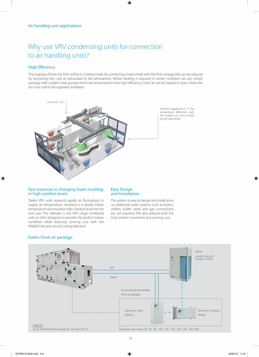
Why use VRV condensing units for connection to air handling units?
High ciency
Fast response to changing loads resulting in high comfort levels
Easy Designand Installation
VRV IV
condensing unit
Electronic interface
(EKEQ)
Expansion valve
(EKEXV)
Factory fi tted and welded
fresh air package
gas
liquid
Daikin Fresh air package
ECPEN15-200A.indd 210 24/03/15 11:37
The majority of time the AHU will be in cooling mode. By combining a heat wheel with the AHU, energy bills can be reduced by recovering the cool air exhausted to the atmosphere. Where heating is required in winter condition we can simply package with a Daikin heat pumps which are renowned for their high efficiency. Fresh air can be heated in cases where the air is too cold to be supplied untreated.
Outside air = 46˚C
Fresh air supplied at 21˚C. The temperature difference with the outdoor air is pre- cooled by the heat wheel.
Daikin VRV units respond rapidly to fluctuations in supply air temprerature, resulting in a steady indoor temperature and resultant high comfort levels for the end user. The ultimate is the VRV range combined with an AHU designed to provide the perfect indoor condition while reducing running cost with the Middle East year round cooling demand.
The system is easy to design and install since no additional water systems such as boilers, chillers, buffer, tanks and gas connections etc. are required. This also reduces both the total system investment and running cost.
Capacity:
Up to 269 kW (Nominal Capacity) - by 4x24 HP OU. Expansion Value Sizes: 50 - 63 - 80 - 100 - 125 - 140 - 200 - 250 - 400 -500
(single or multi)
20
Vent
ilatio
n &
Air
Han
dlin
g
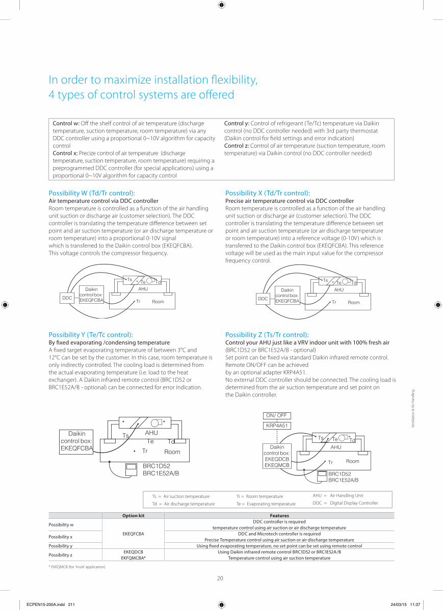
In order to maximize installation fl exibility, 4 types of control systems are off ered
Control w: Off the shelf control of air temperature (discharge temperature, suction temperature, room temperature) via any DDC controller using a proportional 0~10V algorithm for capacity controlControl x: Precize control of air temperature (discharge temperature, suction temperature, room temperature) requiring a preprogrammed DDC controller (for special applications) using a proportional 0~10V algorithm for capacity control
Control y: Control of refrigerant (Te/Tc) temperature via Daikin control (no DDC controller needed) with 3rd party thermostat (Daikin control for fi eld settings and error indication)Control z: Control of air temperature (suction temperature, room temperature) via Daikin control (no DDC controller needed)
Possibility X (Td/Tr control): Precise air temperature control via DDC controllerRoom temperature is controlled as a function of the air handling unit suction or discharge air (customer selection). The DDC controller is translating the temperature diff erence between set point and air suction temperature (or air discharge temperature or room temperature) into a reference voltage (0-10V) which is transferred to the Daikin control box (EKEQFCBA). This reference voltage will be used as the main input value for the compressor frequency control.
Possibility W (Td/Tr control): Air temperature control via DDC controllerRoom temperature is controlled as a function of the air handling unit suction or discharge air (customer selection). The DDC controller is translating the temperature diff erence between set point and air suction temperature (or air discharge temperature or room temperature) into a proportional 0-10V signal which is transferred to the Daikin control box (EKEQFCBA). This voltage controls the compressor frequency.
Possibility Y (Te/Tc control): By fi xed evaporating /condensing temperatureA fi xed target evaporating temperature of between 3°C and12°C can be set by the customer. In this case, room temperature is only indirectly controlled. The cooling load is determined from the actual evaporating temperature (i.e. load to the heat exchanger). A Daikin infrared remote control (BRC1D52 or BRC1E52A/B - optional) can be connected for error indication.
Ts
Tr
TeAHU
Room
TdDaikin
control box:EKEQFCBA
BRC1D52BRC1E52A/B BRC1D52
BRC1E52A/B
Ts
Tr
Te
AHU
Room
TdDaikin
control box:EKEQDCB EKEQMCB
KRP4A51
ON / OFF
Possibility Z (Ts/Tr control): Control your AHU just like a VRV indoor unit with 100% fresh air(BRC1D52 or BRC1E52A/B - optional)Set point can be fi xed via standard Daikin infrared remote control. Remote ON/OFF can be achieved by an optional adapter KRP4A51.No external DDC controller should be connected. The cooling load is determined from the air suction temperature and set point onthe Daikin controller.
* EKEQMCB (for ’multi’ application)
Option kit Features
Possibility w
EKEQFCBA
DDC controller is requiredtemperature control using air suction or air discharge temperature
Possibility xDDC and Microtech controller is required
Precise Temperature control using air suction or air discharge temperaturePossibility y Using fi xed evaporating temperature, no set point can be set using remote control
Possibility zEKEQDCB
EKFQMCBA*Using Daikin infrared remote control or
Temperature control using air suction temperature
Ts = Air suction temperature
Td = Air discharge temperature
Tr = Room temperature
Te = Evaporating temperature
AHU = Air Handling Unit
DDC = Digital Display Controller
DDC
Ts
Tr
TeAHU
Room
Td
Daikincontrol box: EKEQFCBA DDC
Ts
Tr
TeAHU
Room
Td
Daikincontrol box: EKEQFCBA
ECPEN15-200A.indd 211 24/03/15 11:37
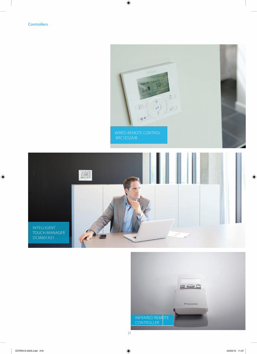
Controllers
INTELLIGENT TOUCH MANAGERDCM601A51
INFRARED REMOTE CONTROLLER
WIRED REMOTE CONTROL BRC1E52A/B
ECPEN15-200A.indd 216 24/03/15 11:37
21
Graphical display of indicative
electricity consumption
(Function available in
combination with FCQG and
FCGHQ)
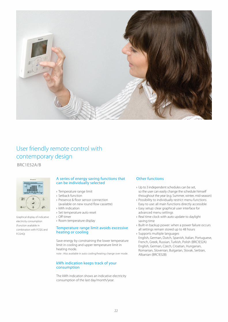
BRC1E52A/B
A series of energy saving functions that can be individually selected
› Temperature range limit › Setback function › Presence & floor sensor connection (available on new round flow cassette)
› kWh indication › Set temperature auto reset › O › Room temperature display
ff timer
Temperature range limit avoids excessive heating or cooling
Save energy by constraining the lower temperature limit in cooling and upper temperature limit in heating mode.note : Also available in auto cooling/heating change over mode.
kWh indication keeps track of your consumption
The kWh indication shows an indicative electricity consumption of the last day/month/year.
Other functions
› so the user can easily change the schedule himself throughout the year (e.g. Summer, winter, mid-season)
› Possibility to individually restrict menu functions Easy to use: all main functions directly accessible
› Easy setup: clear graphical user interface for advanced menu settings
› Real time clock with auto update to daylight saving time
› Built-in backup power: when a power failure occurs
› Supports multiple languages English, German, Dutch, Spanish, Italian, Portuguese,
English, German, Czech, Croatian, Hungarian, Romanian, Slovenian, Bulgarian, Slovak, Serbian,
User friendly remote control with contemporary design
22
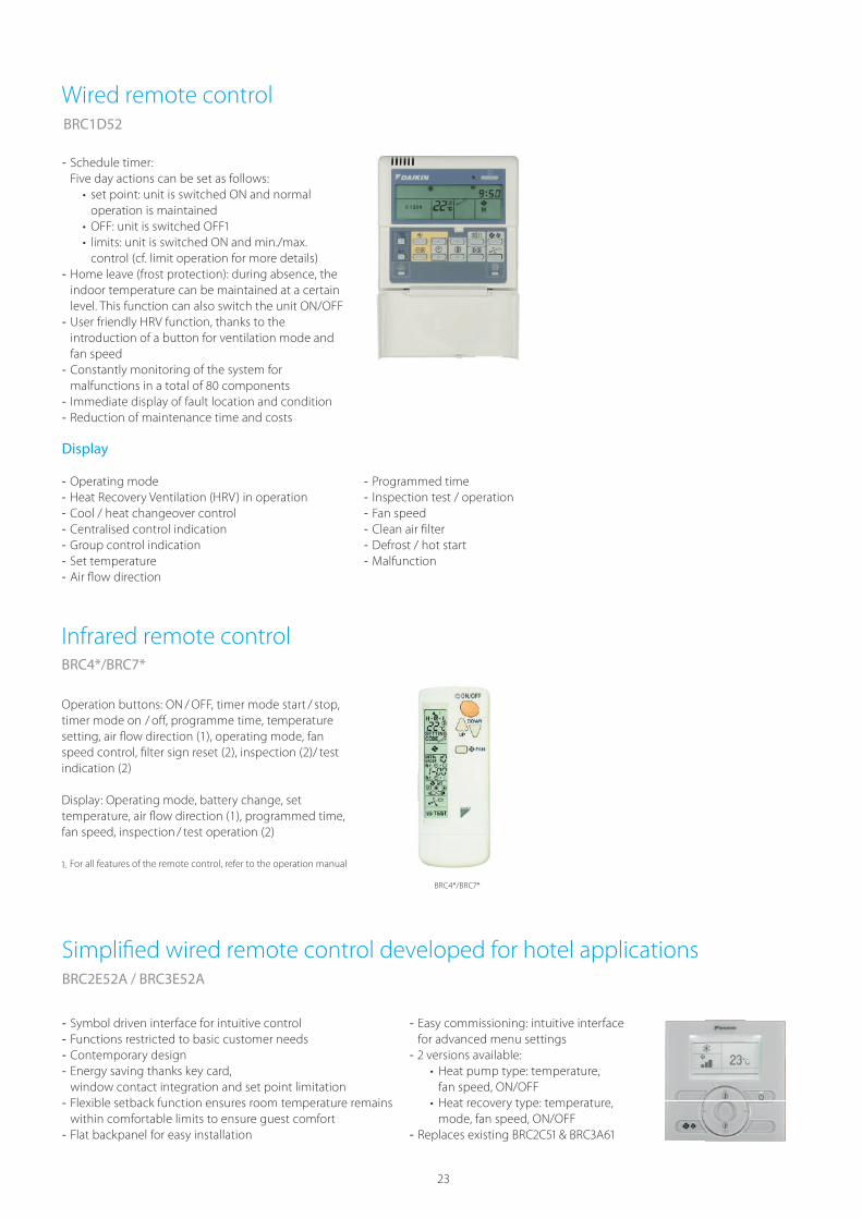
BRC1D52
- Schedule timer:Five day actions can be set as follows:
set point: unit is switched ON and normal operation is maintained
limits: unit is switched ON and min./max. control (cf. limit operation for more details)
- Home leave (frost protection): during absence, the indoor temperature can be maintained at a certain level. This function can also switch the unit ON/OFF
- User friendly HRV function, thanks to the introduction of a button for ventilation mode and fan speed
- Constantly monitoring of the system for
- Immediate display of fault location and condition - Reduction of maintenance time and costs
BRC4*/BRC7*
Operation buttons: ON / OFF, timer mode start / stop, timer mode on / off , programme time, temperature setting, air fl ow direction (1), operating mode, fan speed control, fi lter sign reset (2), inspection (2)/ test indication (2)
Display: Operating mode, battery change, set temperature, air fl ow direction (1), programmed time, fan speed, inspection / test operation (2)
- Symbol driven interface for intuitive control - Functions restricted to basic customer needs - Contemporary design - Energy saving thanks key card, window contact integration and set point limitation
- Flexible setback function ensures room temperature remains within comfortable limits to ensure guest comfort
- Flat backpanel for easy installation
- Easy commissioning: intuitive interface for advanced menu settings
- Heat pump type: temperature, fan speed, ON/OFF
Heat recovery type: temperature, mode, fan speed, ON/OFF
-
BRC2E52A / BRC3E52A
Display
- Operating mode - Heat Recovery Ventilation (HRV) in operation - Cool / heat changeover control - Centralised control indication - Group control indication - Set temperature - Air fl ow direction
- Programmed time - Inspection test / operation - Fan speed - Clean air fi lter - Defrost / hot start - Malfunction
Wired remote control
Infrared remote control
Simplified wired remote control developed for hotel applications
23
24
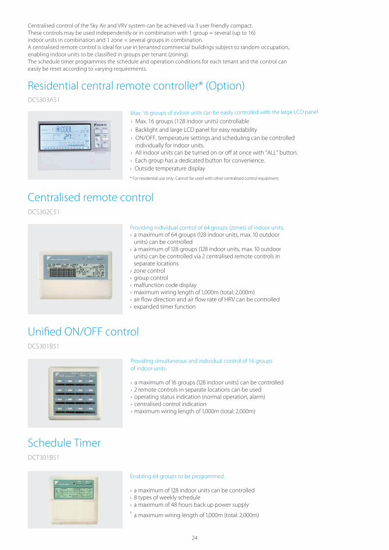
Centralised control of the Sky Air and VRV system can be achieved via 3 user friendly compact.These controls may be used independently or in combination with 1 group = several (up to 16) indoor units in combination and 1 zone = several groups in combination.A centralised remote control is ideal for use in tenanted commercial buildings subject to random occupation, enabling indoor units to be classifi ed in groups per tenant (zoning). The schedule timer programmes the schedule and operation conditions for each tenant and the control can easily be reset according to varying requirements.
›units) can be controlled
›
separate locations › zone control › group control › malfunction code display › › air fl ow direction and air fl ow rate of HRV can be controlled › expanded timer function
Providing simultaneous and individual control of 16 groups of indoor units.
› › › operating status indication (normal operation, alarm) › centralised control indication ›
Enabling 64 groups to be programmed.
› › › ›
Centralised remote controlDCS302C51
Unified ON/OFF controlDCS301B51
Schedule TimerDCT301B51
Residential central remote controller* (Option)DCS303A51
Max. 16 groups of indoor units can be easily controlled with the large LCD panel
› Max. 16 groups (128 indoor units) controllable› Backlight and large LCD panel for easy readability› ON/OFF, temperature settings and scheduling can be controlled
individually for indoor units.› All indoor units can be turned on or off at once with “ALL” button.› Each group has a dedicated button for convenience.› Outside temperature display
* For residential use only. Cannot be used with other centralised control equipment.

25
Cont
rol S
yste
ms
Centralised control systems
DTA113B51
Basic solution for control of Sky Air and VRV
› Rotation function › Backup operation function.
DCS601C51
Detailed & easy monitoring and operation of VRV systems (max. 64 indoor units groups).
Public line
Air conditioning
Network Service
System
third party controller (domotics, BMS, etc.)
Ethernet
DIII-NET
Forced OFF contact input
Onboard
modem
Fire alarm
Indoor units HRV
Languages › English › French › German › Italian › Spanish › Dutch › Portuguese
System layout ›controlled
› Touch panel (full colour LCD via icon display)
Management › Enhanced history function
Control › Individual control (set point, start/stop, fan speed)
› Set back shedule › Enhanced scheduling func-tion
› Flexible grouping in zones › Yearly schedule › Fire emergency stop control › Interlocking control › Increased HRV monitoring and control function
› Automatic cooling / heating change-over
› Heating optimization › Temperature limit ›(general, administration & service)
› Quick selection and full control
› Simple navigation
Monitoring › Icon colour display change function
› Indoor units operation mode › Indication fi lter replacement
Cost performance › Free cooling function › Labour saving › Easy installation › Compact design: limited installation space
› Overall energy saving
Open interface › Communication to any third party controller (domotics, BMS, etc.) is possible via open interface (http option)
Connectable to › VRV › HRV › Sky Air › Split (via interface adapter)

26
Mini Building Management System
Mini BMSwith full integration across all product pillarsSystem overview
NEW
Price competitive mini BMS
Cross-pillar integration of Daikin products
Integration of third party equipment
Direct plug & play connection!
Lighting Fan
SensorPump
Fire alarm
kWh meter
Di/Pi line
Max. 200m
indoor units,
air handling units
Web Access
Fan
coil
units
Chi
llers
and
AH
U
InternetExtranet
LAN3G
Split
I/O
mod
ule
I/O
mod
ule
WAGO
interface
BACnet
protocol
Integration of thirdparty equiqment
Full control of DaikinHVAC-R portfolio
DCM601A51
Multi state objects
AlarmElevator Air handling unit
ITM plus adaptor lineMax. 7 adapters
DCM601A52
Di/Pi port
DCM601A51
Check on
https://www.youtube.com/DaikinEurope

27
Cont
rol S
yste
ms
Plug & play
Mini Building Management System NEW
User friendliness › Intuitive user interface › Visual lay out view and direct access to indoor unit main funtions
› All functions direct accessible via touch screen or via web interface
Smart energy management
› Monitoring if energy use is according to plan › Helps to detect origins of energy waste › Powerful schedules guarantee correct operation throughout the year
› Save energy by interlocking A/C operation with other equiment such as heating
Flexibility
› Cross-pillar integration (heating, air conditioning, applied systems, refrigeration, air handling units)
› › I/O for integration of equipment such as lights, pumps… on WAGO modules
› Modular concept for small to large applications ›and combine multiple ITM via the web interface
Easy servicing and commissioning
› Remote refrigerant containment check preventing on site visit
› Simplifi ed troubleshooting › Save time on commissioning thanks to the pre-commissioning tool
› Auto registration of indoor units
Functions overview
Languages › English
› French
› German
› Italian
› Spanish
› Dutch
› Portuguese
Management › Web access
› Power Proportional
Distribution (option)
› Operational history
(malfunctions, operation hours, …)
› Smart energy management
- monitor if energy use is
according to plan
- detect origins of energy
waste
› Setback function
› Sliding temperature
System layout ›
be controlled
(incl. iTM adaptor)
› Ethernet TCPIP
Control › Individual control
› Schedule setting (Weekly
schedule, yearly calender,
seasonal schedule)
› Interlock control
› Setpoint limitation
› Temperature limit
Connectable to- DX Split, Sky Air, VRV
- Daikin AHU
- Fan coils
- Daikin Altherma Flex type
- LT and HT hydroboxes
- Air curtains
- WAGO I/O, AO and PI
- BACnet protocol
WAGO Interface ›
party equipment
- WAGO coupler (interface
between WAGO and Modbus)
- Di module
- Do module
- Ai module
- Thermistor module
NEW
NEW
NEW
NEW
Flexibility in size
From 64 up to ∞ number
of groups
Split Fan coils Chillers and AHU Refrigeration

28
What is Intelligent Network?A service based on our global remote monitoring technology, keeping your system trouble-free and working with top efficiency.
VRV Cloud
24/7
CLOUD
performance monitoring and analysis
Intelligent Network SevicesWhat does Intelligent Network offer youSafeguarding the lifelong optimum operation of your air conditioning system means getting geared up to operate the system in energy efficient way and reduce unexpected breakdowns and costs to the absolute minimum. This is where Intelligent Network helps to improve the effectiveness of your building management.
Intelligent Network is about ‘being connected’ with Daikin, the Internet-based link between you, your air conditioning system and Daikin’s Remote Monitoring Centre. This allows you to monitor your energy consumption and Daikin’s expert service engineers to monitor your entire system’s status non-stop, all year round. Through predicting malfunctions and offering technical advice from data analysis, you can maximise equipment uptime, as well as controlling energy costs with no sacrifice in comfort levels. By doing this, Intelligent Network will prevent problems, prolong your system’s service life while reducing the energy bill.
Intelligent Network consists of 2 main services: The VRV Cloud and Intelligent Network performance monitoring and analysis.
The VRV Cloud puts you in the driving seat of your energy management. The easy-to use energy data trending and analytic tools puts you in control and shows your CO2 footprint reduction opportunities and energy savings of up to 15%.
Saving starts by measuring. Enhance your company’s sustainability !
Intelligent Network performance monitoringand analysisFocus on your core business and hand the HVAC over to Daikin. Daikin Intelligent Network connects your system continuously with Daikin. It notifies alarms and early warnings of system deviations to maximise system uptime and the comfort of the people in the building. Service providers have web based access to operation data so that they are fully prepared when they arrive on-site. Specialists run trend analyses.All of which boosts your system’s reliability by ensuring that it is running at optimum efficiency.
Intelligent Network

29
Daikin VRV Cloud Helps you manage your energy through Daikin technology. › Intelligent energy visualization tool that helps you with your energy management
›location.
› User friendly visualization of VRV energy management (kWh)
› Analysis support of waste operation › Multiple site monitoring
Performance monitoring
Fast response, better prepared
› If an alarm does occur, the service provider is immediately alerted and receives all crucial information.
›
24/7
Information to:
› customers
› service company
Monitor your energy
managment.
Performance supervision
and analysis
Data server
Internet
Prediction analysis
Data trend logging
CLOUD
› Performance Supervision by Daikin experts enhances a maintenance plan.
› This service aims to enhance the service level, to respond fast and accurate, to save on unexpected repair costs and assure the peace of mind. Repetitive interventions and disturbance of building tenants and maintenance teams are kept to a minimum.
Long lifetime systems
›
AnalysisBe connected with Daikin’s experts, this gives you a clear overview of operability and use of the air conditioning system. › Daikin continuously monitors energy, operation and comfort data. Thanks to periodic analysis of the data, Daikin can suggest ways of improving performance.
› if there is a problem, Daikin specialists will analyse the operation data history to provide remote support.
Controller
Daikin’s unique Intelligent Network Service aims to prevent the equipment coming to an unexpected stop or needing emergency repair.
Early fault indication (predictions) : operation data are 24/7 checked by Intelligent Network prediction algorithms to act as early as possible, averting unscheduled breakdowns.
Intelligent Network will maximise the installation’s lifetime, by ensuring the equipment runs in optimal conditions and avoid unnecessary stress on components.
I
Connection with Intelligent Network via
TM, PCASO, ...

30
RXYTQ-T7YF
VRV IV heat pump
(4)
CTonCapacity
apacity kW 22
6.4 8.0 9.5 11.4 12.8
.4 28.0 33.5 40.0 45.0
Capacity Btu/h 76,450 95,550 114,350 136,500 153,550
EER (Btu/h) / W 12.1 12.8 11.8 11.0 11.0
PI kW
kWW/W
6.3
4.58
4.89
4.81
5.82
4.13
8.11
3.72
10.8
3.50
12.9
3 7.47 9.68 12.4 14.0
Capacity kW 20.2 25.2 28.5 32.0 35.1
Capacity Btu/h 68,950 86,000 97,250 109,200 119,800
EE
EER outPI out
R (Btu/h) / W 9.28 9.90 9.72 9.45 9.18
PI kW 7.43 8.69 10.0 11.6 13.0
Cooling T1 35oC(1)
(Nominal)
C
T1-Eurovent(2)
ooling T3 46oC(3)
Model RXYTQ8T7YF RXYTQ10T7YF RXYTQ12T7YF RXYTQ14T7YF RXYTQ16T7YF
Capacity kW 16.8 22.4 24.0 25.1 28.4
Capacity Btu/h 57,350 76,450 81,900 85,650 96,950
kW/Ton 1.30 1.30 1.30 1.28 1.29
EER 9.21 9.25 9.21 9.35 9.28
PI kW 6.22 8.29 8.89 9.16 10.4
Cooling T2 48oC
(Btu/h) / W
Capacity kW 22.4 28.0 33.5 40.0 45.0
Capacity Btu/h 76,450 95,550 114,350 136,500 153,550
COP (Btu/h) / W 13.2 12.7 12.0 12.2 11.8
PI kW 5.20 6.67 8.54 9.98 11.7
Sound power dBA 78 81 81 86 86
Sound pressure dBA 58 61 61 64 64
Dimensions H x W x D 1680x930x765
-5 ~ 55˚CDB (6)
14 ~ 25˚CWB
-20 ~ 15,5˚CWB
15 ~ 27˚CDB50 ~ 130%
Total: 50 -110% (VRV Indoor : 50-110%)
80 ~ 110%
R-410A
AHU only
VRV indoor unit only
Type
Operation range cooling
Operation range Heating
Heating (nominal)(5)
Sound level (nominal)
1680 x 1240 x 765
(1) indoor temperature: 26,7°CD B, 19,4°CWB, outdoor temperature: 35°CDB, AHRI 1230:2010, power input indoor units (duct type) included. As per AHRI/ SASO
(2) Outdoor energy efficiency rating and power input based on Eurovent testing and listing of the 50Hz models only. As per Estidama
(5) Heating capacities are based on: indoor temperature: 20°CDB, outdoor temperature: 7°CDB, 6°CWB, Eurovent 2015, equivalent refrigerant piping: 5m, level difference: 0m.
(6) Verified by 3rd party laboratory (Intertek- USA)
(4) indoor temperature: 26,6°CDB, 19,4°CWB, outdoor temperature: 48°CDB, AHRI 1230:2010, power input indoor units (duct type) included. As per MEW
(3) indoor temperature: 29,0°CDB, 19,0°CWB, outdoor temperature: 46°CDB, ISO15042:2011, power input indoor units (duct type) included. As per ESMA
m 100064
Ø 9.52 mmØ 19.01 mm
Ø 9.52 mmØ 22.2 mm
Ø 12.7 mmØ 28.6 mmGas
Liquid
CompressorsPower Supply
1 1 1 2 2
Total Wiring Length : 2000 m
3 Phase/ 380-415V/ 50Hz 3 Phase/400 V / 60Hz
Wiring Length
P
Total Piping Length System Actual Max. connectable indoor units
ipe Connection
Refrigerant
Connection Ratio
OutdoorIndoorOutdoorIndoor
VRV indoor + AHU
6.57 8.29 8.64 10.17 11.63PI out kW
5.93 7.80 8.43 8.65 9.87PI out kW

VRV IV water cooled series - 50Hz
RWEYQ-T
Geothermal operationStandard operation
Outdoor unit RWEYQ T T T T T T T T TSystem Outdoor unit modul RWEYQ T RWEYQ T RWEYQ T RWEYQ T RWEYQ T RWEYQ T
Outdoor unit modul - RWEYQ T RWEYQ T RWEYQ T RWEYQ TOutdoor unit modul - RWEYQ T RWEYQ T
Capacity range HPCooling capacity Nom. kW . . . . . .Heating capacity Nom. kW . . . .Power input - Hz Cooling Nom. kW . . . . . . . .
Heating Nom. kW . . . . . . .EER . . . . . . . . .COP . . . . . . . . .Maximum number of connectable indoor unitsIndoor index connection
Min.Nom.Max.
Dimensions Unit HeightxWidthxDepth mm , x x -Weight Unit kg -Sound pressure level Cooling Nom. dBAOperation range Inlet water
temperatureCooling Min.~Max. °CDB ~Heating Min.~Max. °CWB - ~
Refrigerant Type / GWP R- A/ , .Charge kg/ TCO Eq . / . . / . -
Piping connections Liquid OD mm . . .Gas OD mm . ( ) . ( ) . ( ) . ( )Discharge gas OD mm . ( ) / . ( ) . ( ) / . ( ) . ( ) / . ( ) . ( ) / . ( )Water Inlet/Outlet PT / B internal thread/PT / B internal threadTotal piping length System Actual m
Power supply Phase/Frequency/Voltage Hz/V N~/ / -Current - Hz Maximum fuse amps (MFA) A
( In case of heat pump system, gas pipe is not used ( In case of heat recovery system ( ) In case of heat pump system ( Not Eurovent certifi edContains fl uorinated greenhouse gases
31
ECPEN15-206A.indd 30 24/03/15 11:50
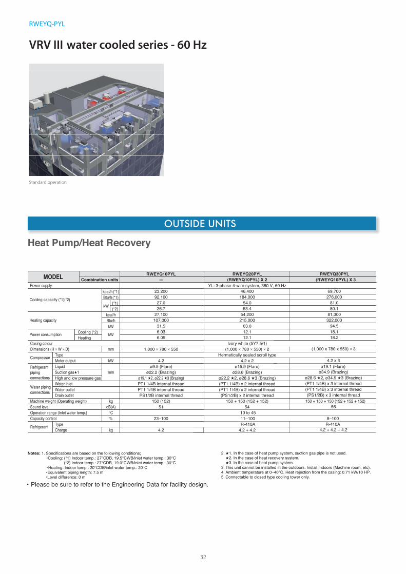
VRV III water cooled series - 60 Hz
RWEYQ-PYL
Standard operation
32
OUTSIDE UNITS
kW
mm
%
kg
mm
kgdB(A)
Power supply
TypeCompressor
Refrigerant
Dimensions (H x W x D)
Motor output
Casing colour
MODEL
LiquidRefrigerant piping connections
Type
Sound levelMachine weight (Operating weight)
Suction gas 1
Capacity control
Charge
High and low pressure gas
Water piping connections
Water inlet
Drain outletWater outlet
Cooling capacity (*1)(*2)
Heating capacity
Power consumptionHeatingCooling (*2)
Operation range (Inlet water temp.)
Combination units
Hermetically sealed scroll type1,000 x 780 x 550
4.2
Ivory white (5Y7.5/1)
ø9.5 (Flare)
R-410A
51150 (152)
ø22.2 (Brazing)
23–100
4.2
ø19.1 2, ø22.2 3 (Brazing)PT1 1/4B internal thread
PS1/2B internal threadPT1 1/4B internal thread
Notes: 1. Specifications are based on the following conditions;•Cooling: (*1) Indoor temp.: 27°CDB, 19.5°CWB/inlet water temp.: 30°C
(*2) Indoor temp.: 27°CDB, 19.0°CWB/inlet water temp.: 30°C•Heating: Indoor temp.: 20°CDB/inlet water temp.: 20°C•Equivalent piping length: 7.5 m•Level difference: 0 m
2. 1. In the case of heat pump system, suction gas pipe is not used.2. In the case of heat recovery system.3. In the case of heat pump system.
3. This unit cannot be installed in the outdoors. Install indoors (Machine room, etc).4. Ambient temperature at 0–40°C. Heat rejection from the casing: 0.71 kW/10 HP.5. Connectable to closed type cooling tower only.
• Please be sure to refer to the Engineering Data for facility design.
Heat Pump/Heat Recovery
Btu/h(*1)(*1)kW (*2)
kcal/h(*1)
kWBtu/hkcal/h
kW
°C 10 to 45
(1,000 x 780 x 550) x 2
4.2 x 2ø15.9 (Flare)
54150 + 150 (152 + 152)
ø28.6 (Brazing)
11–100
4.2 + 4.2
(PT1 1/4B) x 2 internal thread
(PS1/2B) x 2 internal thread(PT1 1/4B) x 2 internal thread
ø22.2 2, ø28.6 3 (Brazing)
23,20092,100
27.026.7
27,100107,000
31.56.036.05
RWEYQ10PYL—
46,400184,000
54.053.4
54,200215,000
63.012.112.1
RWEYQ20PYL(RWEYQ10PYL) X 2
4.2 x 3
R-410A
ø19.1 (Flare)
56150 + 150 + 150 (152 + 152 + 152)
8–100
4.2 + 4.2 + 4.2
ø34.9 (Brazing)
(PT1 1/4B) x 3 internal thread
(PS1/2B) x 3 internal thread(PT1 1/4B) x 3 internal thread
ø28.6 2, ø34.9 3 (Brazing)
YL: 3-phase 4-wire system, 380 V, 60 Hz
RWEYQ30PYL(RWEYQ10PYL) X 3
69,700276,000
81.080.1
81,300322,000
94.518.118.2
(1,000 x 780 x 550) x 3


DMEA 16-094
VRV Con gurator Software For Simpli ed Commissioning, Con guration and Customization
Variable Refrigerant Temperature Customize your VRV for best Seasonal E ciency and Comfort
Refrigerant Cooled-PCB Reliable Cooling Designed for High Ambient Temperatures
w w w . d a i k i n m e a . c o m
+ + MAXcomfort
QUICKinstallation
FASTdesign
Daikin Europe N.V. participates in the Eurovent Certification programme for Liquid Chilling Packages (LCP), Air handling units (AHU), Fan coil units (FCU) and variable refrigerant flow systems (VRF) Check ongoing validity of certificate online: www.eurovent-certification.com or using: www.certiflash.com -Applicable for 50Hz only.
The present publication is drawn up by way of information only and does not constitute an offer binding upon Daikin MEA. Daikin MEA has compiled the content of this publication to the best of its knowledge. No express or implied warranty is given for the completeness, accuracy, reliability or fitness for particular purpose of its content and the products and services presented therein. Specifications are subject to change without prior notice. Daikin MEA explicitly rejects any liability for any direct or indirect damage, in the broadest sense, arising from or related to the use and/or interpretation of this publication. All content is copyrighted by Daikin MEA.
Email: in Web: [email protected]
Daikin Middle East and Africa
Independently tested by