Volume Graphics (2006), T. Möller, R. Machiraju, T. Ertl ...
5
©The Eurographics Association 2006. Volume Graphics (2006), T. Möller, R. Machiraju, T. Ertl, M. Chen (Editors) 1. Introduction Volume rendering has become an integral technology in many areas of science, engineering, and medicine, and even entertainment thanks to the emergence of programmable graphics hardware (GPUs), available at affordable cost everywhere. The use of graphics hardware for volume ren- dering began with SGI workstations equipped with 2D and 3D texture mapping hardware and progressed to early gener- ations of PC-grade graphics boards [RSKB*], which prop- erly shifted and composited a set of axis aligned slices in front-to-back order. Pre-integrated volume rendering [EKE01] was later introduced to cope with under-sampling artifacts, that were produced when the above scheme was used with oblique viewing directions. The accelerated view- ing capabilities enabled interactive transfer function design with a multi-dimensional framework [KKH02]. Accelera- tion techniques, such as early ray termination and empty space skipping [LMK03], and hierarchical acceleration structures [GWGS02] were also introduced. The slice-based rendering scheme was retained until the render-to-texture capabilities emerged, facilitating the storage of intermediate results onto textures and effectively driving program flow. This, in fact, gave rise to the ubiquitous GPGPU movement, and enabled the departure from the slice-compositing scheme of the early years. A noteworthy contribution in this regard is the paper by Krueger and Westermann [KW03], who implemented a ray caster on the GPU. This effort was followed by Weiskopf et al. [WSE04], who extended this framework to non-linear ray tracing. Both methods explic- itly enforced the program flow by rendering control poly- gons for every major step of the ray casting algorithm, using textures to hold the intermediate computation results. The repeated sequence of individual steps are: advancing the rays, interpolation of samples in the 3D data texture, shad- ing, compositing. While the programming model of graphics hardware is already SIMD (Single Instruction/Multiple Data, where the parallel processor performs the same opera- tions on different data), the explicit decomposition and enforcement of the volume rendering process into these var- ious pipeline steps created an even stronger SIMD lockstep processing mode. This gave rise to significant overheads associated with rendering the control polygon at each step, and requiring multiple passes. The upside to this is that due to the strong decomposition, rays that have become opaque could be eliminated (terminated) between steps and empty space could be culled [KW03]. Hadwiger et al.[HSS*05] presented a GPU-ray casting system for isosurface rendering which uses a block-based space-skipping acceleration scheme and performs screen-space shading. Splatting was also accelerated on the GPU using early-z culling [NK05]. Finally, Xue et al. [XZC05] introduced isosurface-aided hardware acceleration techniques to slice-based rendering, and Weiler et al. [WMKE04] provided a hardware acceler- ated ray-casting framework for rendering texture encoded tetrahedral strips. The addition of loop and branch capabilities into the GPU programming set has enabled the more natural and free- flowing pipeline execution mode used in single-pass ray- casting [SSKE05]. In the new ray casting programs, a ray is first initialized and then steps across the volume and repeat- edly executes all pipeline steps to integrate the discrete vol- ume rendering integral. This only requires a single control polygon to be rendered, sending the ray fragments on their ways. We have found that the present framework lacks the capabilities to focus program flow on the relevant data, and, due to the GPU-native SIMD programming model, the slow- est ray determines the rendering speed. We explore solutions to enforce better control over the rendering process, with the special SIMD programming model in mind, giving speedups of up to 8. 2. Single-Pass Ray-Casting The latest generation of NVidia and ATI hardware, which support the DirectX Pixel Shader 3.0 API and NVIDIA's NV_fragment_program2 extension, enabled the introduction of single-pass ray-casting. This improved approach, thor- oughly described in [SSKE05], takes advantage of the new branching and looping capabilities of the GPU in order to completely eliminate the need for intermediate passes required in previous implementations [KW03]. These addi- tional passes were necessary to trace through the entire 3D volume, but also to stop rays that are outside of the volume or in already opaque regions. Single-pass ray-casting is significantly faster than multi- pass ray-casting when rendering in semi-transparent mode, where very few rays will terminate due to opacity. Since the- oretically the two approaches have exactly the same com- plexity, the difference in performance is defined by their overheads. In this case, the single-pass approach has much SIMD-Aware Ray-Casting Warren Leung Neophytos Neophytou Klaus Mueller Center for Visual Computing, Computer Science, Stony Brook University Abstract With the addition of loop and branch capabilities into the GPU programming set, a more natural and free-flowing vol- ume rendering pipeline execution mode recently emerged. While the execution of the looped fragment program is still SIMD, the numerical approximation of the volume integral is no longer broken up into multiple passes, as it was in pre- vious approaches. Although this certainly is an improvement, due to the less tight control, the present framework lacks the capabilities to focus program flow on the relevant data. In fact, due to the GPU-native SIMD programming model, the slowest ray will now determine the rendering speed. Our paper seeks to provide solutions to enforce more control over the rendering process, with the special SIMD programming model in mind, while retaining this new and promising single-pass rendering paradigm. Our efforts were rewarded with speedups of up to 8.
Transcript of Volume Graphics (2006), T. Möller, R. Machiraju, T. Ertl ...
©The Eurographics Association 2006.
Volume Graphics (2006),T. Möller, R. Machiraju, T. Ertl, M. Chen (Editors)
1. Introduction
Volume rendering has become an integral technology inmany areas of science, engineering, and medicine, and evenentertainment thanks to the emergence of programmablegraphics hardware (GPUs), available at affordable costeverywhere. The use of graphics hardware for volume ren-dering began with SGI workstations equipped with 2D and3D texture mapping hardware and progressed to early gener-ations of PC-grade graphics boards [RSKB*], which prop-erly shifted and composited a set of axis aligned slices infront-to-back order. Pre-integrated volume rendering[EKE01] was later introduced to cope with under-samplingartifacts, that were produced when the above scheme wasused with oblique viewing directions. The accelerated view-ing capabilities enabled interactive transfer function designwith a multi-dimensional framework [KKH02]. Accelera-tion techniques, such as early ray termination and emptyspace skipping [LMK03], and hierarchical accelerationstructures [GWGS02] were also introduced. The slice-basedrendering scheme was retained until the render-to-texturecapabilities emerged, facilitating the storage of intermediateresults onto textures and effectively driving program flow.This, in fact, gave rise to the ubiquitous GPGPU movement,and enabled the departure from the slice-compositingscheme of the early years. A noteworthy contribution in thisregard is the paper by Krueger and Westermann [KW03],who implemented a ray caster on the GPU. This effort wasfollowed by Weiskopf et al. [WSE04], who extended thisframework to non-linear ray tracing. Both methods explic-itly enforced the program flow by rendering control poly-gons for every major step of the ray casting algorithm, usingtextures to hold the intermediate computation results. Therepeated sequence of individual steps are: advancing therays, interpolation of samples in the 3D data texture, shad-ing, compositing. While the programming model of graphicshardware is already SIMD (Single Instruction/MultipleData, where the parallel processor performs the same opera-tions on different data), the explicit decomposition andenforcement of the volume rendering process into these var-ious pipeline steps created an even stronger SIMD lockstepprocessing mode. This gave rise to significant overheadsassociated with rendering the control polygon at each step,and requiring multiple passes. The upside to this is that dueto the strong decomposition, rays that have become opaque
could be eliminated (terminated) between steps and emptyspace could be culled [KW03]. Hadwiger et al.[HSS*05]presented a GPU-ray casting system for isosurface renderingwhich uses a block-based space-skipping accelerationscheme and performs screen-space shading. Splatting wasalso accelerated on the GPU using early-z culling [NK05].Finally, Xue et al. [XZC05] introduced isosurface-aidedhardware acceleration techniques to slice-based rendering,and Weiler et al. [WMKE04] provided a hardware acceler-ated ray-casting framework for rendering texture encodedtetrahedral strips.
The addition of loop and branch capabilities into the GPUprogramming set has enabled the more natural and free-flowing pipeline execution mode used in single-pass ray-casting [SSKE05]. In the new ray casting programs, a ray isfirst initialized and then steps across the volume and repeat-edly executes all pipeline steps to integrate the discrete vol-ume rendering integral. This only requires a single controlpolygon to be rendered, sending the ray fragments on theirways. We have found that the present framework lacks thecapabilities to focus program flow on the relevant data, and,due to the GPU-native SIMD programming model, the slow-est ray determines the rendering speed. We explore solutionsto enforce better control over the rendering process, with thespecial SIMD programming model in mind, giving speedupsof up to 8.2. Single-Pass Ray-Casting
The latest generation of NVidia and ATI hardware, whichsupport the DirectX Pixel Shader 3.0 API and NVIDIA'sNV_fragment_program2 extension, enabled the introductionof single-pass ray-casting. This improved approach, thor-oughly described in [SSKE05], takes advantage of the newbranching and looping capabilities of the GPU in order tocompletely eliminate the need for intermediate passesrequired in previous implementations [KW03]. These addi-tional passes were necessary to trace through the entire 3Dvolume, but also to stop rays that are outside of the volumeor in already opaque regions.
Single-pass ray-casting is significantly faster than multi-pass ray-casting when rendering in semi-transparent mode,where very few rays will terminate due to opacity. Since the-oretically the two approaches have exactly the same com-plexity, the difference in performance is defined by theiroverheads. In this case, the single-pass approach has much
SIMD-Aware Ray-CastingWarren Leung Neophytos Neophytou Klaus Mueller
Center for Visual Computing, Computer Science, Stony Brook University
AbstractWith the addition of loop and branch capabilities into the GPU programming set, a more natural and free-flowing vol-ume rendering pipeline execution mode recently emerged. While the execution of the looped fragment program is stillSIMD, the numerical approximation of the volume integral is no longer broken up into multiple passes, as it was in pre-vious approaches. Although this certainly is an improvement, due to the less tight control, the present framework lacksthe capabilities to focus program flow on the relevant data. In fact, due to the GPU-native SIMD programming model,the slowest ray will now determine the rendering speed. Our paper seeks to provide solutions to enforce more controlover the rendering process, with the special SIMD programming model in mind, while retaining this new and promisingsingle-pass rendering paradigm. Our efforts were rewarded with speedups of up to 8.
©The Eurographics Association 2006.
W. Leung, N.Neophytou & K. Mueller / SIMD-Aware Ray Casting
less overheads.In certain scenarios, such as iso-surface rendering, and in
cases where the opacity accumulates faster, depending onthe transfer function, the multi-pass approach can beexpected to perform better, since certain hard-wired optimi-zations including early-z culling can be applied to eliminatefragments from rendering on subsequent passes. These opti-mizations take advantage of the local coherence of neigh-boring rays since the whole process is inherentlysynchronized to lock-step.
The current single-pass implementations, including theone by [SSKE05] rely on a similar property of the SIMDprocessing pipeline that performs the fragment processing.More specifically, all the fragments that are “in flight” (thatis the group of fragments that are being processed at thefragment pipeline at a given moment), are essentially run inlock-step. This means that all the fragments included in thiscurrently processing group share the same instructioncounter. So, if these fragments are executing a data depen-dent loop, then all the fragments within this group will eitherbe working, or in the worst case, idle-processing until all ofthe fragments are ready to exit the loop.
The exact size of the “in-flight” fragment region is undis-closed by hardware manufacturers as it varies across differ-ent graphics hardware models, brands, and differentgenerations of the same model, but it is expected to be a fewhundred in the GeForce 6 series GPU [KF05]. This, depend-ing on the fragment positioning in certain regions of the vol-ume, translates to a few pixels/rays being able todramatically slow-down the performance of the wholescene. In fact, it was also observed in [SSKE05] that early -ray termination even when rendering iso-surfaces using afull volume shader does not give performance that is consis-tent with what we have observed with previous approachesthat use multi-pass rendering combined with early-z culling.
To verify this assumption, we have tested the single-passray-casting approach on a full volume rendering task butsetting the transfer function to define iso-surface rendering.
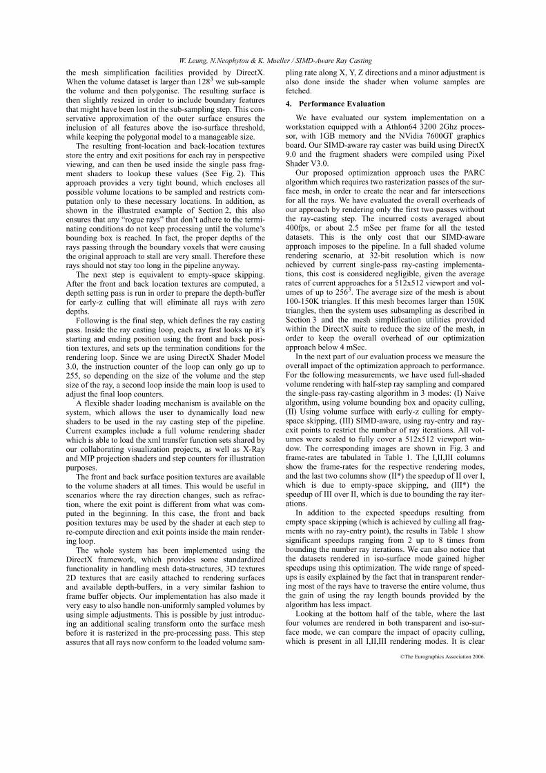
Therefore, the alpha channel should saturate very quickly,and by adding a simple check inside the rendering loopshould terminate the ray as soon as the alpha passes theopacity threshold. In the example shown in Fig. 1, we illus-trate the number of iterations executed in each ray. In sub-figures (b) and (c) darker shades of red depict less iterationsfor the pixel. We can clearly see that a group of edge pixels,which do not accumulate enough alpha to reach the thresh-old, keep executing until they reach the volume bounds.Unfortunately, because of the way the fragments are pro-cessed inside the GPUs SIMD pipeline, these “rogue pixels”were able to slow down the whole scene down to about 8times compared to the frame-rates of our suggested opti-mized implementation. The iteration counts of the optimizedrenderer are shown in Fig. 1c, where we can see that for theiso-surface case all the pixels in the scene render with simi-lar very shallow rays.
Experiences such as the above clearly suggest the neces-sity for an optimization scheme which takes into account thespecific characteristics of each volume dataset and ensuresthat the rendering pipeline is fully utilized most of the time.3. Implementation
A very simple yet quite effective and efficient accelera-tion approach for ray casting was proposed as early as 1995in [SA95]. The Polygon Assisted Ray Casting algorithm(PARC) uses the hardware pipeline to acquire the pixel loca-tions of the front and back surfaces of the dataset. This isdone by rendering a polygonal model of the volume into twodifferent target textures, using a two-pass approach similarto depth-peeling, where depth-buffer testing is used to ren-der the front-most and back-most surfaces separately. Theresulting textures can then be used to define the beginningand end of each ray. In the original implementation ofPARC, this information was later read in back to the CPUand used later to accelerate the software based ray castingengine.
Our suggested single-pass ray casting method uses apolygonal model that is computed only once, using a simpleiso-surfacing approach such as the marching cubes [LC87],based on the opacity assignments of the current transferfunction. The algorithm then introduces a setup step at thebeginning of the pipeline, which renders the polygonalmodel and stores the entry and exit points for each ray of thescene, as the PARC approach requires. The size of thepolygonal model is kept at about 100-150K triangles using
Figure 1: Example of SIMD ray-casting slowdown. (a) Aniso-surface rendering of the foot dataset (viewport512x512). Unoptimized frame-rate: 9.5 fps, Optimizedframe-rate: 57fps. (b) Number of iterations per fragmentfor unoptimized SIMD ray casting. Darker red color equalsto less iterations. (c) Number of iterations per fragment foroptimized SIMD ray casting. We can notice from (b) thatjust a few fragments are causing a slowdown of about 8.
(a)
(b)
(c)
fps=10
fps=79
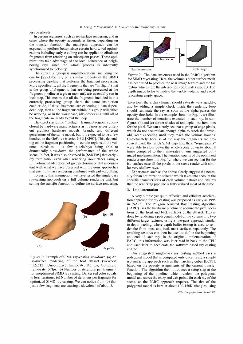
Near Intersection
Far Intersection
Depth Image
Figure 2: The data structures used in the PARC algorithmfor SIMD raycasting. Here, the volume’s outer surface meshhas been used to produce the near image texture and the fartexture which store the intersection coordinates in RGB. Thedepth image helps to isolate the visible volume and avoidraycasting empty space.
©The Eurographics Association 2006.
W. Leung, N.Neophytou & K. Mueller / SIMD-Aware Ray Casting
the mesh simplification facilities provided by DirectX.When the volume dataset is larger than 1283 we sub-samplethe volume and then polygonise. The resulting surface isthen slightly resized in order to include boundary featuresthat might have been lost in the sub-sampling step. This con-servative approximation of the outer surface ensures theinclusion of all features above the iso-surface threshold,while keeping the polygonal model to a manageable size.
The resulting front-location and back-location texturesstore the entry and exit positions for each ray in perspectiveviewing, and can then be used inside the single pass frag-ment shaders to lookup these values (See Fig. 2). Thisapproach provides a very tight bound, which encloses allpossible volume locations to be sampled and restricts com-putation only to these necessary locations. In addition, asshown in the illustrated example of Section 2, this alsoensures that any “rogue rays” that don’t adhere to the termi-nating conditions do not keep processing until the volume’sbounding box is reached. In fact, the proper depths of therays passing through the boundary voxels that were causingthe original approach to stall are very small. Therefore theserays should not stay too long in the pipeline anyway.
The next step is equivalent to empty-space skipping.After the front and back location textures are computed, adepth setting pass is run in order to prepare the depth-bufferfor early-z culling that will eliminate all rays with zerodepths.
Following is the final step, which defines the ray castingpass. Inside the ray casting loop, each ray first looks up it’sstarting and ending position using the front and back posi-tion textures, and sets up the termination conditions for therendering loop. Since we are using DirectX Shader Model3.0, the instruction counter of the loop can only go up to255, so depending on the size of the volume and the stepsize of the ray, a second loop inside the main loop is used toadjust the final loop counters.
A flexible shader loading mechanism is available on thesystem, which allows the user to dynamically load newshaders to be used in the ray casting step of the pipeline.Current examples include a full volume rendering shaderwhich is able to load the xml transfer function sets shared byour collaborating visualization projects, as well as X-Rayand MIP projection shaders and step counters for illustrationpurposes.
The front and back surface position textures are availableto the volume shaders at all times. This would be useful inscenarios where the ray direction changes, such as refrac-tion, where the exit point is different from what was com-puted in the beginning. In this case, the front and backposition textures may be used by the shader at each step tore-compute direction and exit points inside the main render-ing loop.
The whole system has been implemented using theDirectX framework, which provides some standardizedfunctionality in handling mesh data-structures, 3D textures2D textures that are easily attached to rendering surfacesand available depth-buffers, in a very similar fashion toframe buffer objects. Our implementation has also made itvery easy to also handle non-uniformly sampled volumes byusing simple adjustments. This is possible by just introduc-ing an additional scaling transform onto the surface meshbefore it is rasterized in the pre-processing pass. This stepassures that all rays now conform to the loaded volume sam-
pling rate along X, Y, Z directions and a minor adjustment isalso done inside the shader when volume samples arefetched.4. Performance Evaluation
We have evaluated our system implementation on aworkstation equipped with a Athlon64 3200 2Ghz proces-sor, with 1GB memory and the NVidia 7600GT graphicsboard. Our SIMD-aware ray caster was build using DirectX9.0 and the fragment shaders were compiled using PixelShader V3.0.
Our proposed optimization approach uses the PARCalgorithm which requires two rasterization passes of the sur-face mesh, in order to create the near and far intersectionsfor all the rays. We have evaluated the overall overheads ofour approach by rendering only the first two passes withoutthe ray-casting step. The incurred costs averaged about400fps, or about 2.5 mSec per frame for all the testeddatasets. This is the only cost that our SIMD-awareapproach imposes to the pipeline. In a full shaded volumerendering scenario, at 32-bit resolution which is nowachieved by current single-pass ray-casting implementa-tions, this cost is considered negligible, given the averagerates of current approaches for a 512x512 viewport and vol-umes of up to 2563. The average size of the mesh is about100-150K triangles. If this mesh becomes larger than 150Ktriangles, then the system uses subsampling as described inSection 3 and the mesh simplification utilities providedwithin the DirectX suite to reduce the size of the mesh, inorder to keep the overall overhead of our optimizationapproach below 4 mSec.
In the next part of our evaluation process we measure theoverall impact of the optimization approach to performance.For the following measurements, we have used full-shadedvolume rendering with half-step ray sampling and comparedthe single-pass ray-casting algorithm in 3 modes: (I) Naivealgorithm, using volume bounding box and opacity culling,(II) Using volume surface with early-z culling for empty-space skipping, (III) SIMD-aware, using ray-entry and ray-exit points to restrict the number of ray iterations. All vol-umes were scaled to fully cover a 512x512 viewport win-dow. The corresponding images are shown in Fig. 3 andframe-rates are tabulated in Table 1. The I,II,III columnsshow the frame-rates for the respective rendering modes,and the last two columns show (II*) the speedup of II over I,which is due to empty-space skipping, and (III*) thespeedup of III over II, which is due to bounding the ray iter-ations.
In addition to the expected speedups resulting fromempty space skipping (which is achieved by culling all frag-ments with no ray-entry point), the results in Table 1 showsignificant speedups ranging from 2 up to 8 times frombounding the number ray iterations. We can also notice thatthe datasets rendered in iso-surface mode gained higherspeedups using this optimization. The wide range of speed-ups is easily explained by the fact that in transparent render-ing most of the rays have to traverse the entire volume, thusthe gain of using the ray length bounds provided by thealgorithm has less impact.
Looking at the bottom half of the table, where the lastfour volumes are rendered in both transparent and iso-sur-face mode, we can compare the impact of opacity culling,which is present in all I,II,III rendering modes. It is clear
©The Eurographics Association 2006.
W. Leung, N.Neophytou & K. Mueller / SIMD-Aware Ray Casting
from this part of the table, that opacity culling (early ray ter-mination based on alpha accumulation) has much lessimpact on performance in rendering modes I and II, a resultthat is also consistent with what was observed in [SSKE05].On the other hand, the SIMD-aware approach enables opac-ity culling to have a more significant impact on perfor-mance, and it is consistent with the results of the past slicebased approaches.
Overall, these results justify the use the PARC algorithmto accelerate single-pass ray-casting despite the incurredcosts of at most 2-4 mSec per frame.Conclusions
In this paper we have explored solutions that addresssome of the problems of current single-pass ray-castingalgorithms, which utilize the latest features on GPU hard-ware such as loop flow control and branch capabilities. Wehave identified that the main flaw of the current SIMD ray-casting systems lies with the fact that very few unboundedrays are allowed to slow down the entire scene. We haveproposed the use of the PARC (Polygon Assisted Ray Cast-ing) algorithm, in order to ensure that all rays are bounded tothe limits of the volume’s outermost surface. We also pro-vided a performance analysis which shows that for the mini-mal cost of about 2-4 mSec per frame, one can gain up to 8times speedup on typical volumes. We are currently focus-ing on a load-balanced SIMD-aware ray casting system.Acknowledgements
This research was supported, in part, by NIH grant5R21EB004099-02 and NSF-CAREER grant ACI-0093157.
References[CCF94] B. Cabral, N. Cam, J. Foran, “Accelerated Volume
Rendering and Tomographic Reconstruction using Tex-ture Mapping Hardware,” Proc. Symposium on VolumeVisualization ‘94, pp. 91.98, 1994.
[CN93] T. Cullip, U. Neumann, “Accelerating VolumeReconstruction With 3D Texture Hardware,” Tech. Rep.TR93-027, Univ. of North Carolina at Chapel Hill, 1993.
[EKE01] K. Engel, M. Kraus, T. Ertl, “High-Quality Pre-Integrated Volume Rendering Using Hardware-Acceler-ated Pixel Shading,” Eurographics / SIGGRAPHWorkshop on Graphics Hardware '01, pp. 9.16, 2001.
[GWGS02] S. Guthe, M. Wand, J. Gonser, W. Straßer,“Interactive Rendering of Large Volume Data Sets,”Proc. of IEEE Visualization '02, pp. 53-60, 2002.
[HSS*05] M. Hadwiger, C. Sigg, H. Scharsach, K. Buehler,M. Gross, “Real- Time Ray-Casting and Advanced Shad-ing of Discrete Isosurfaces,” Proc. Eurographics '05, pp.303.312, 2005.
[KKH02] J. Kniss, G. Kindlmann, C. Hansen, “Multidimen-sional Transfer Functions for Interactive VolumeRendering,” IEEE Trans. on Visualization and ComputerGraphics, vol. 8, no. 3, 270-285, 2002.
[KW03] J. Krueger, R. Westermann, “Acceleration Tech-niques for GPUbased Volume Rendering,” Proc. of IEEEVisualization '03, pp. 287.292, 2003.
[LMK03] W. Li, K. Mueller, A. Kaufman, “Empty SpaceSkipping and Occlusion Clipping for Texture-based Vol-ume Rendering,” Proc IEEE Visualization '03, pp. 317-324, 2003.
[NK05] N. Neophytou and K. Mueller, "GPU acceleratedimage aligned splatting," Volume Graphics Workshop2005, pp. 197-205, June 2005.
[RSKB*] C. Rezk-Salama, K. Engel, M. Bauer, G. Greiner,and T. Ertl, “Interactive Volume Rendering on StandardPC Graphics Hardware using Multi-textures and Multi-stage Rasterization,” Proc. ACM SIGGRAPH/EURO-GRAPHICS Work. on Graph. Hardware, pp. 109-118,2000.
[SSKE05] S. Stegmaier, M. Strengert, T. Klein, T. Ertl, “ASimple and Flexible Volume Rendering Framework forGraphics-Hardware-based Raycasting,” Volume Graph-ics Workshop ‘05, pp. 187-195, 2005.
[WSE04] D. Weiskopf, T. Schafhitzel, T. Ertl, “GPU-BasedNonlinear Ray Tracing,” Comput. Graph. Forum, vol. 23,no. 3, pp. 625-634, 2004.
[SA95] L. Sobierajski and R. Avila, "A Hardware Accelera-tion Method for Volumetric Ray Tracing," Proc.Visualization`95, pp. 27-34, 1995.
[LC87] Lorensen, W.E. and Cline, H.E., “Marching Cubes:a high resolution 3D surface reconstruction algorithm”,Comp. Graph., 21-4, pp 163-169 (SIGGRAPH), 1987.
[WMKE04] M. Weiler, P. N. Mallón, M. Kraus, T. Ertl,“Texture-Encoded Tetrahedral Strips”, Symposium onVolume Visualization 2004, pp. 71-78.
[XZC05] D. Xue, C. Zhang, R. Crawfis, "Isbvr: isosurface-aided hardware acceleration techniques for slice-basedvolume rendering." Volume Graphics 2005, pp. 207-214.
[KF05] E. Kilgariff and R. Fernando. "The GeForce 6 SeriesGPU Architecture", in GPU Gems 2, Addison-Wesley2005.
TABLE 1. Impact of SIMD-aware ray-casting approach. (I)Naive raycasting using volume bounding box (II) Empty-space skipping (III) SIMD-Aware with ray bounds (II*) Speedup of II over I, (III*) Speedup of III over II.
Volume Size I II III II* III*
Lobster 3202x36 4.0 7.0 32.0 1.8 4.6Bonsai 1283 3.4 8.5 16.9 2.5 2.0Aneurism 1283 3.4 10 32.0 2.9 3.2Foot Trs. 1283 3.1 7.8 35.0 2.5 4.5Foot Iso 1283 3.6 10 79.0 2.7 8.0Teddy 1283 4.0 4.7 13.0 1.2 2.8CT-Head 1283 4.6 5.1 14.0 1.1 2.7Engine trs 2563 3.1 3.3 13.0 1.1 3.9Engine iso 2563 5.0 10.5 38.0 2.1 3.6VisMale trs 2563 3.9 4.5 10.3 1.2 2.3Vis Male iso 2563 3.2 5.5 30.6 1.7 5.6Foot Cat. trs 2563 3.2 3.7 11.0 1.2 3.0Foot Cat. iso 2563 5.4 5.5 17.0 1.0 3.1Frog trs 2562x44 3.2 6.9 25.0 2.2 3.6Frog iso 2562x44 3.3 11.3 37.0 3.4 3.3
©The Eurographics Association 2006.
W. Leung, N.Neophytou & K. Mueller / SIMD-Aware Ray Casting
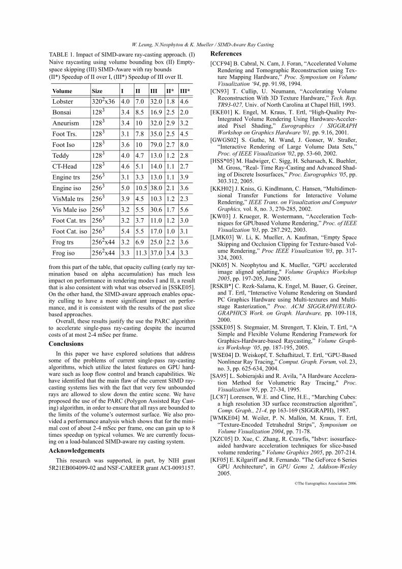
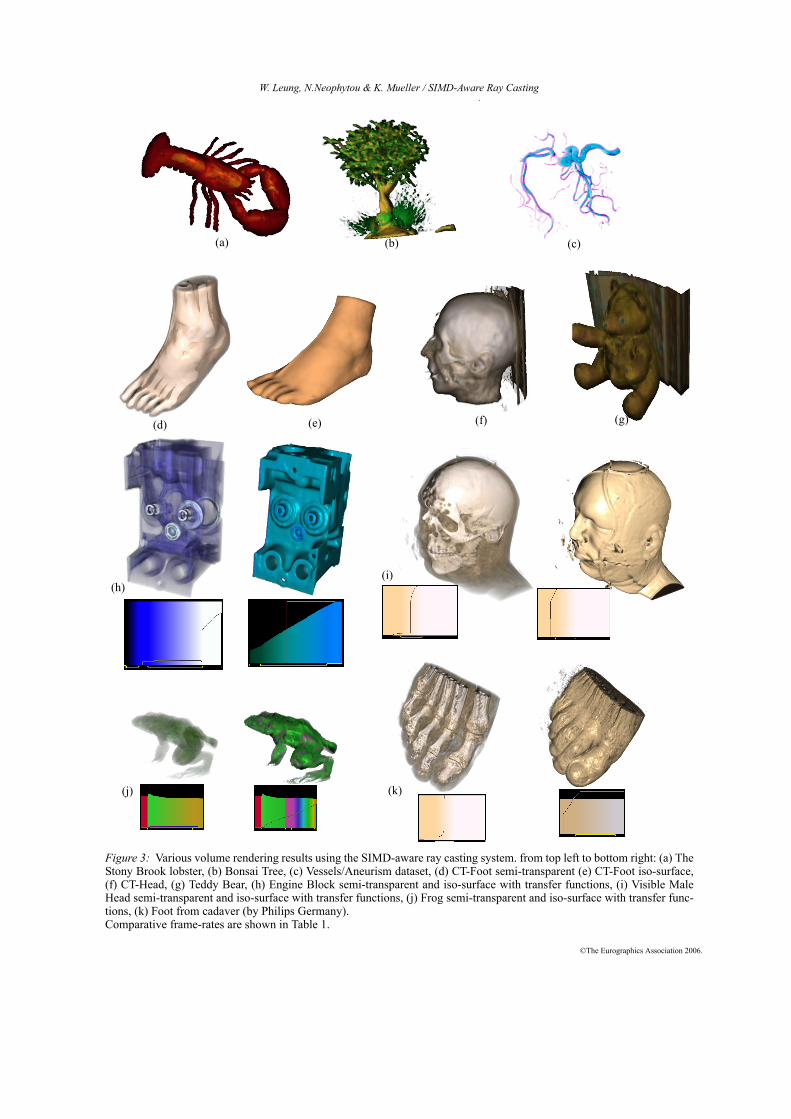
Figure 3: Various volume rendering results using the SIMD-aware ray casting system. from top left to bottom right: (a) TheStony Brook lobster, (b) Bonsai Tree, (c) Vessels/Aneurism dataset, (d) CT-Foot semi-transparent (e) CT-Foot iso-surface,(f) CT-Head, (g) Teddy Bear, (h) Engine Block semi-transparent and iso-surface with transfer functions, (i) Visible MaleHead semi-transparent and iso-surface with transfer functions, (j) Frog semi-transparent and iso-surface with transfer func-tions, (k) Foot from cadaver (by Philips Germany). Comparative frame-rates are shown in Table 1.
(h)
(j) (k)
(i)
(a) (b) (c)
(d) (e) (f) (g)