Vol. 8, No. 5, 2017 High Precision DCT CORDIC ... · PDF fileHigh Precision DCT CORDIC...
9
(IJACSA) International Journal of Advanced Computer Science and Applications, Vol. 8, No. 5, 2017 High Precision DCT CORDIC Architectures for Maximum PSNR Imen Ben Saad Universite ´ de Tunis El Manar Faculte ´ des Sciences de Tunis, LAPER, UR-17-ES11, Campus Universitaire 2092, El Manar. Sonia Mami Universite ´ de Tunis El Manar Faculte ´ des Sciences de Tunis, LAPER, UR-17-ES11, Campus Universitaire 2092, El Manar. Yassine Hacha¨ ıchi Universite ´ de Carthage, TUNISIA. ENICarthage Universite ´ de Tunis El Manar, TUNISIA. LAMSIN-ENIT Younes Lahbib Universite ´ de Carthage, TUNISIA. ENICarthage Universite´ de Monastir, TUNISIA. Electronics and Micro-electronics Laboratory Abdelkader Mami Universite ´ de Tunis El Manar Faculte ´ des Sciences de Tunis, LAPER, UR-17-ES11, Campus Universitaire 2092, El Manar. Abstract—This paper proposes two optimal Cordic Loeffler based DCT (Discrete Cosine Transform algorithm) architectures: a fast and low Power DCT architecture and a high PSNR DCT architecture. The rotation parameters of CORDIC angles required for these architectures have been calculated using a MATLAB script. This script allows the variation of the angle’s precision from 10 -1 to 10 -4 . The experimental results show that the fast and low Power DCT architecture correponds to the precision 10 -1 . Its complexity is even lower than the BinDCT which is a reference in terms of low complexity and its power has been enhanced in comparison with the conventional Cordic Loeffler DCT by 12 mW. The experimental results also show that the high PSNR DCT architecture corresponds to the precision 10 -3 for which the PSNR has been improved by 6.55 dB in comparison with the conventional Cordic Loeffler DCT. Then, the hardware implementation and the generated RTL of some required Cordics are presented. Keywords—Cordic Loeffler DCT; high quality architecture; low power architecture; Image Processing; DCT I. I NTRODUCTION The Discrete Cosine Transform DCT was developed by Ahmed et.al in 1974 [1]. It is a robust approximation of the optimal Karhunen-Loeve Transform (KLT) [2]. It has become one of the most widely used techniques of transforms in digital signal processing. Many works deal with the optimization of the DCT archi- tectures. Two principal axes are explored. The first one consists on the enhancement of the quality of the DCT in terms of precision measured through the Peak Signal to Noise Ratio (PSNR) ([3], [4]). The reference in this case is the Loeffler based DCT which is the most precise architecture since it doesn’t contain approximations. The second axe consist on improve the DCT in terms of power consumption ([5], [6], [7]). In fact, it is well-known that DCT is one of the computationally intensive transforms since it requires many multiplications and additions. Many researches had been done on low-power DCT designs [8], [9]. As the multiplications are energy expensive operations, several algorithms are based on additions and shifts instead of multiplications. In 2004, Jeong et al. [9] suggested improving a Cordic (COordinate Rotation Digital Computer) based implementation of the DCT. CORDIC is an algorithm which can be used to evaluate various functions in signal processing [10], [11], [12]. In [9], authors proposed a low-complexity CORDIC based DCT algorithm based on the Flow Graph Algorithm (FGA) which is the commonly used way to represent the fast DCT. It requires only 38 add and 16 shift operations and consumes about 26.1 % less power compared to [13],with a minor image quality degradation of 0.04 dB. In the same direction, Sun et .al [14], [15] proposed a new flow graph for Cordic based Loeffler DCT implementation. A new table of parameters is obtained with new choice of the elementary rotations. Their experimental result shows that the Cordic-based Loeffler DCT consumes 16% of energy compared to [16] with a minor image quality degradation of 0.03 dB. After this analysis of state of the art, we remark that previous works have almost neglected the quality of the results provided by the DCT algorithm in order to decrease the energy consumption. In the aformentioned works, the reached preci- sion degree is at most 10 -4 . We propose to remain in the same interval (10 -1 to 10 -4 ) and provide 2 optimal architectures. The first one is a fast and low power DCT architecture and the second one is a high PSNR DCT architecture. The parameters of the two architectures are obtained from a Matlab script which calculates the rotation parameters of the considered angles. Contribution in this paper are: • A matlab script which calculates the CORDIC param- www.ijacsa.thesai.org 502 | P a g e
Transcript of Vol. 8, No. 5, 2017 High Precision DCT CORDIC ... · PDF fileHigh Precision DCT CORDIC...

(IJACSA) International Journal of Advanced Computer Science and Applications,Vol. 8, No. 5, 2017
High Precision DCT CORDIC Architectures forMaximum PSNR
Imen Ben SaadUniversite de Tunis El Manar
Faculte des Sciences de Tunis, LAPER, UR-17-ES11,
Campus Universitaire 2092, El Manar.
Sonia MamiUniversite de Tunis El Manar
Faculte des Sciences de Tunis, LAPER, UR-17-ES11,
Campus Universitaire 2092, El Manar.
Yassine HachaıchiUniversite de Carthage, TUNISIA.
ENICarthageUniversite de Tunis El Manar, TUNISIA.
LAMSIN-ENIT
Younes LahbibUniversite de Carthage, TUNISIA.
ENICarthageUniversite´ de Monastir, TUNISIA.
Electronics and Micro-electronics Laboratory
Abdelkader MamiUniversite de Tunis El Manar
Faculte des Sciences de Tunis, LAPER, UR-17-ES11,
Campus Universitaire 2092, El Manar.
Abstract—This paper proposes two optimal Cordic Loefflerbased DCT (Discrete Cosine Transform algorithm) architectures:a fast and low Power DCT architecture and a high PSNRDCT architecture. The rotation parameters of CORDIC anglesrequired for these architectures have been calculated using aMATLAB script. This script allows the variation of the angle’sprecision from 10−1 to 10−4. The experimental results show thatthe fast and low Power DCT architecture correponds to theprecision 10−1. Its complexity is even lower than the BinDCTwhich is a reference in terms of low complexity and its powerhas been enhanced in comparison with the conventional CordicLoeffler DCT by 12 mW. The experimental results also show thatthe high PSNR DCT architecture corresponds to the precision10−3 for which the PSNR has been improved by 6.55 dB incomparison with the conventional Cordic Loeffler DCT. Then,the hardware implementation and the generated RTL of somerequired Cordics are presented.
Keywords—Cordic Loeffler DCT; high quality architecture; lowpower architecture; Image Processing; DCT
I. INTRODUCTION
The Discrete Cosine Transform DCT was developed byAhmed et.al in 1974 [1]. It is a robust approximation of theoptimal Karhunen-Loeve Transform (KLT) [2]. It has becomeone of the most widely used techniques of transforms in digitalsignal processing.
Many works deal with the optimization of the DCT archi-tectures. Two principal axes are explored. The first one consistson the enhancement of the quality of the DCT in terms ofprecision measured through the Peak Signal to Noise Ratio(PSNR) ([3], [4]). The reference in this case is the Loefflerbased DCT which is the most precise architecture since itdoesn’t contain approximations.
The second axe consist on improve the DCT in terms ofpower consumption ([5], [6], [7]). In fact, it is well-knownthat DCT is one of the computationally intensive transforms
since it requires many multiplications and additions. Manyresearches had been done on low-power DCT designs [8],[9]. As the multiplications are energy expensive operations,several algorithms are based on additions and shifts instead ofmultiplications.
In 2004, Jeong et al. [9] suggested improving a Cordic(COordinate Rotation Digital Computer) based implementationof the DCT. CORDIC is an algorithm which can be used toevaluate various functions in signal processing [10], [11], [12].In [9], authors proposed a low-complexity CORDIC basedDCT algorithm based on the Flow Graph Algorithm (FGA)which is the commonly used way to represent the fast DCT.It requires only 38 add and 16 shift operations and consumesabout 26.1 % less power compared to [13],with a minor imagequality degradation of 0.04 dB.
In the same direction, Sun et .al [14], [15] proposed a newflow graph for Cordic based Loeffler DCT implementation.A new table of parameters is obtained with new choice ofthe elementary rotations. Their experimental result shows thatthe Cordic-based Loeffler DCT consumes 16% of energycompared to [16] with a minor image quality degradation of0.03 dB.
After this analysis of state of the art, we remark thatprevious works have almost neglected the quality of the resultsprovided by the DCT algorithm in order to decrease the energyconsumption. In the aformentioned works, the reached preci-sion degree is at most 10−4. We propose to remain in the sameinterval (10−1 to 10−4) and provide 2 optimal architectures.The first one is a fast and low power DCT architecture and thesecond one is a high PSNR DCT architecture. The parametersof the two architectures are obtained from a Matlab scriptwhich calculates the rotation parameters of the consideredangles.
Contribution in this paper are:
• A matlab script which calculates the CORDIC param-
www.ijacsa.thesai.org 502 | P a g e

(IJACSA) International Journal of Advanced Computer Science and Applications,Vol. 8, No. 5, 2017
eters of the desired angles.
• A high PSNR DCT architecture which is the closestto the reference in terms of image quality (the Loefflerbased DCT [16]) with significant power reduction.
• a fast and low power DCT architecture which is theclosest to the reference in terms of low complexity(The BinDCT [17]) with substancial PSNR improve-ment.
This paper is organized as follows. Section 2 brieflyintroduces the algorithms of conventional Cordic-Based DCTArchitecture. In Section 3, the proposed architectures and theirCordic parameters are presented. The experimental results areshown in Section 4 while Section 5 concludes this paper.
II. CONVENTIONAL CORDIC-BASED DCTARCHITECTURE
A. Cordic Algorithm
The conventional Cordic algorithm [10], [11] is hardware-efficient used for the approximation computation of the tran-scendental functions. It only uses shift and addition operations.The Cordic algorithm can operate in two modes, namelyvectoring and rotation and in this paper, the first mode isfocused on.
In the conventional Cordic algorithm, a rotation angle isdecomposed into a combination of micro-rotation angles ofarctangent radix. When the vector is rotated by an angle θi,the coordinate changed from (Xi, Yi) to (Xi+1, Yi+1).
The value of vector after this micro rotation can be repre-sented as:(
xiyi
)=
(cos(θi) −σi sin(θi)σi sin(θi) cos(θi)
)(xi+1
yi+1
)= Ki
(1 −σi2−i
σi2−i 1
)(xi+1
yi+1
) (1)
where θi = arctan(2−i), σi = ±1 and Ki = cos(θi).
The circular rotation angle is depicted as:
θ =∑
σiθi where σi = ±1 (2)
Fig. 1. The direct implementation of equation 1
In the equation (1), only shift and add operations arerequired to perform the rotation angle described in Fig. 1. But,the results of the rotation iterations need to be scaled by a
compensation (scale) factor K. This can be done by using thefollowing iterative method.
K =∏i
Ki =∏i
1√1 + 2−2i
(3)
The scale factor K which can be interpreted as a constantgain (hence not data dependent) can be tolerated in manydigital signal processing applications. Hence, it should becarefully investigated whether it is necessary to compensate forthe scaling at all. If scale factor correction cannot be avoided,two possibilities are known. The first approach consists onperforming a constant factor multiplication with 1/Ki. Thesecond method is based on extending the Cordic iteration in away that the resulting inverse of the scale factor takes a value.In other words, writing the scaling factor as a sum of 2−i
where i must be determined so that the error is minimized,is needed. In the rotation mode, the angle accumulator isinitialized with the desired rotation angle. The rotation decisionat each iteration is made to diminish the magnitude of theresidual angle in the accumulator one. The decision at eachiteration is therefore based on the sign of the residual angleafter each step [10].
B. Cordic-Based DCT Architecture
The One-dimensional DCT for 8x8 sub-images is definedas
X(t) =1
2C(t)
7∑i=0
x(i) cos
[(2i+ 1)tπ
16
]
C(t) =
{ √22 if t = 01 otherwise
(4)
Where x(i) is the input data and X(t) is 1-D DCTtransformed output data.
The two-dimensional DCT is a separable transform. It canbe executed by one-dimensional DCT in a serial manner asshown in the Fig. 2.
Fig. 2. 8× 8, 2-D DCT processor with separable 1-D DCT
The 1-D DCT transform is represented by the Equation 5- 12.
X(0) = x(0)+x(1)+x(2)+x(3)+x(4)+x(5)+x(6)+x(7)(5)
X(1) =(x(0)− x(7)
)cos(π/16) +
(x(1)− x(6)
)cos(3π/16)
+(x(3)− x(4)
)sin(π/16) +
(x(2)− x(5)
)sin(3π/16)
(6)
X(2) =(x(1) + x(6)− x(2)− x(5)
)cos(3π/8)
+(x(0) + x(7)− x(3)− x(4)
)sin(3π/16)
(7)
www.ijacsa.thesai.org 503 | P a g e
(IJACSA) International Journal of Advanced Computer Science and Applications,Vol. 8, No. 5, 2017
X(3) =(x(0)− x(7)
)cos(3π/16)−
(x(3)− x(4)
)sin(3π/16)
−(x(2)− x(5)
)cos(π/16)−
(x(1)− x(6)
)sin(π/16)
(8)
X(4) =(x(0)+x(3)+x(4)+x(7)
)−(x(1)+x(2)+x(5)+x(6)
)(9)
X(5) =(x(3)− x(4)
)cos(3π/16) +
(x(0)− x(7)
)sin(3π/16)
−(x(1)− x(6)
)cos(π/16) +
(x(2)− x(5)
)sin(π/16)
(10)
X(6) =(x(0) + x(7)− x(3)− x(4)
)cos(3π/8)
−(x(1) + x(6)− x(2)− x(5)
)sin(3π/8)
(11)
X(7) =(x(0)− x(7)
)sin(π/16)−
(x(1)− x(6
)) sin(3π/16)
−(x(2)− x(5)
)cos(3π/16)−
(x(3)− x(4)
)cos(π/16)
(12)
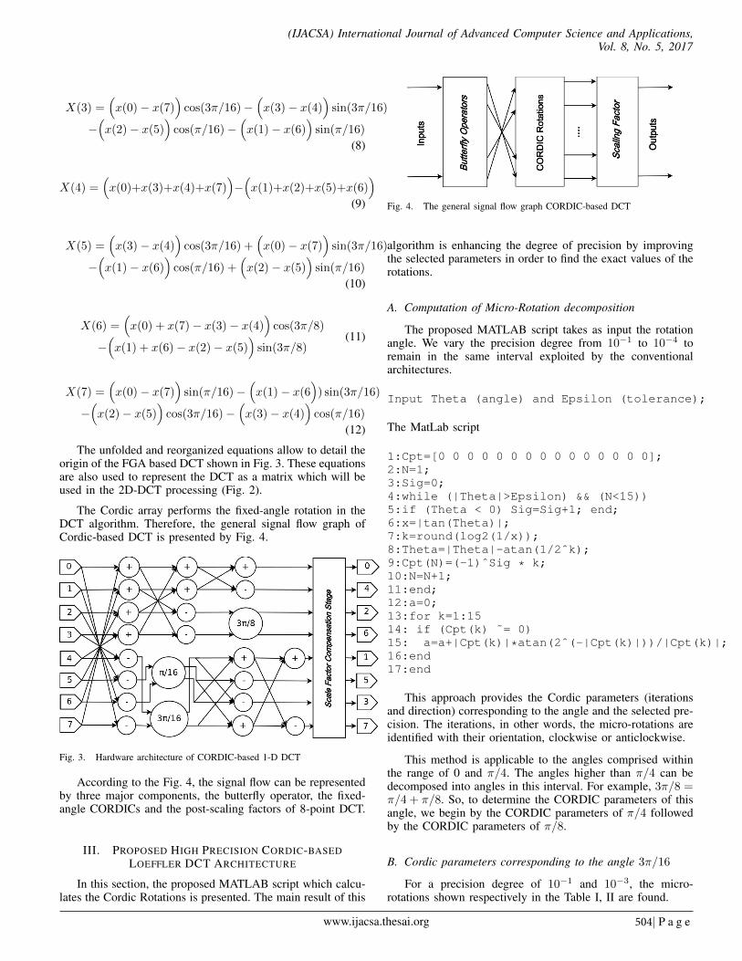
The unfolded and reorganized equations allow to detail theorigin of the FGA based DCT shown in Fig. 3. These equationsare also used to represent the DCT as a matrix which will beused in the 2D-DCT processing (Fig. 2).
The Cordic array performs the fixed-angle rotation in theDCT algorithm. Therefore, the general signal flow graph ofCordic-based DCT is presented by Fig. 4.
Fig. 3. Hardware architecture of CORDIC-based 1-D DCT
According to the Fig. 4, the signal flow can be representedby three major components, the butterfly operator, the fixed-angle CORDICs and the post-scaling factors of 8-point DCT.
III. PROPOSED HIGH PRECISION CORDIC-BASEDLOEFFLER DCT ARCHITECTURE
In this section, the proposed MATLAB script which calcu-lates the Cordic Rotations is presented. The main result of this
Fig. 4. The general signal flow graph CORDIC-based DCT
algorithm is enhancing the degree of precision by improvingthe selected parameters in order to find the exact values of therotations.
A. Computation of Micro-Rotation decomposition
The proposed MATLAB script takes as input the rotationangle. We vary the precision degree from 10−1 to 10−4 toremain in the same interval exploited by the conventionalarchitectures.
Input Theta (angle) and Epsilon (tolerance);
The MatLab script
1:Cpt=[0 0 0 0 0 0 0 0 0 0 0 0 0 0 0];2:N=1;3:Sig=0;4:while (|Theta|>Epsilon) && (N<15))5:if (Theta < 0) Sig=Sig+1; end;6:x=|tan(Theta)|;7:k=round(log2(1/x));8:Theta=|Theta|-atan(1/2ˆk);9:Cpt(N)=(-1)ˆSig * k;10:N=N+1;11:end;12:a=0;13:for k=1:1514: if (Cpt(k) ˜= 0)15: a=a+|Cpt(k)|*atan(2ˆ(-|Cpt(k)|))/|Cpt(k)|;16:end17:end
This approach provides the Cordic parameters (iterationsand direction) corresponding to the angle and the selected pre-cision. The iterations, in other words, the micro-rotations areidentified with their orientation, clockwise or anticlockwise.
This method is applicable to the angles comprised withinthe range of 0 and π/4. The angles higher than π/4 can bedecomposed into angles in this interval. For example, 3π/8 =π/4 + π/8. So, to determine the CORDIC parameters of thisangle, we begin by the CORDIC parameters of π/4 followedby the CORDIC parameters of π/8.
B. Cordic parameters corresponding to the angle 3π/16
For a precision degree of 10−1 and 10−3, the micro-rotations shown respectively in the Table I, II are found.
www.ijacsa.thesai.org 504| P a g e
(IJACSA) International Journal of Advanced Computer Science and Applications,Vol. 8, No. 5, 2017
TABLE I. DETERMINING THE CORDIC PARAMETERS FOR 3π/16 CORRESPONDING TO A PRECISION DEGREE OF 10−1
θ = 3π/16 x = |tanθ| i=round(-log2(x)) θ = |θ| − tan−1(2−1) σ Stop Condition|θ| < ε
Iteration1 x=0.6682 1 θ = 0.1254 + 0.125 > 10−1
Iteration2 x=0.1261 3 θ = 0.001 + 0.001 < 10−1
End of process
TABLE II. DETERMINING THE CORDIC PARAMETERS FOR 3π/16 CORRESPONDING TO A PRECISION DEGREE OF 10−3
θ = 3π/16 x = |tanθ| i=round(-log2(x)) θ = |θ| − tan−1(2−1) σ Stop Condition|θ| < ε
Iteration1 x=0.6682 1 θ = 0.1254 + 0.125 > 10−3
Iteration2 x=0.1261 3 θ = 0.001 + 0.001 > 10−3
Iteration3 x= 0.0010 10 θ = 6.9457e− 05 + 6.9457e− 05 < 10−3
End of process
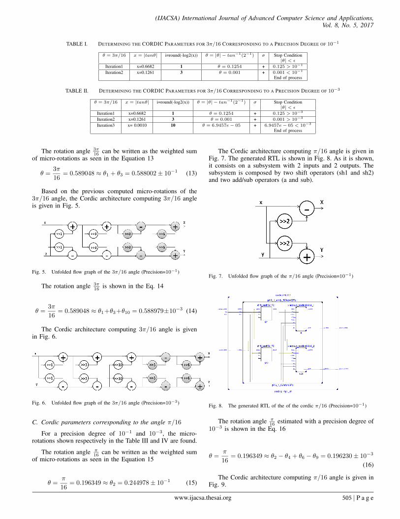
The rotation angle 3π16 can be written as the weighted sum
of micro-rotations as seen in the Equation 13
θ =3π
16= 0.589048 ≈ θ1 + θ3 = 0.588002± 10−1 (13)
Based on the previous computed micro-rotations of the3π/16 angle, the Cordic architecture computing 3π/16 angleis given in Fig. 5.
Fig. 5. Unfolded flow graph of the 3π/16 angle (Precision=10−1)
The rotation angle 3π16 is shown in the Eq. 14
θ =3π
16= 0.589048 ≈ θ1+θ3+θ10 = 0.588979±10−3 (14)
The Cordic architecture computing 3π/16 angle is givenin Fig. 6.
Fig. 6. Unfolded flow graph of the 3π/16 angle (Precision=10−3)
C. Cordic parameters corresponding to the angle π/16
For a precision degree of 10−1 and 10−3, the micro-rotations shown respectively in the Table III and IV are found.
The rotation angle π16 can be written as the weighted sum
of micro-rotations as seen in the Equation 15
θ =π
16= 0.196349 ≈ θ2 = 0.244978± 10−1 (15)
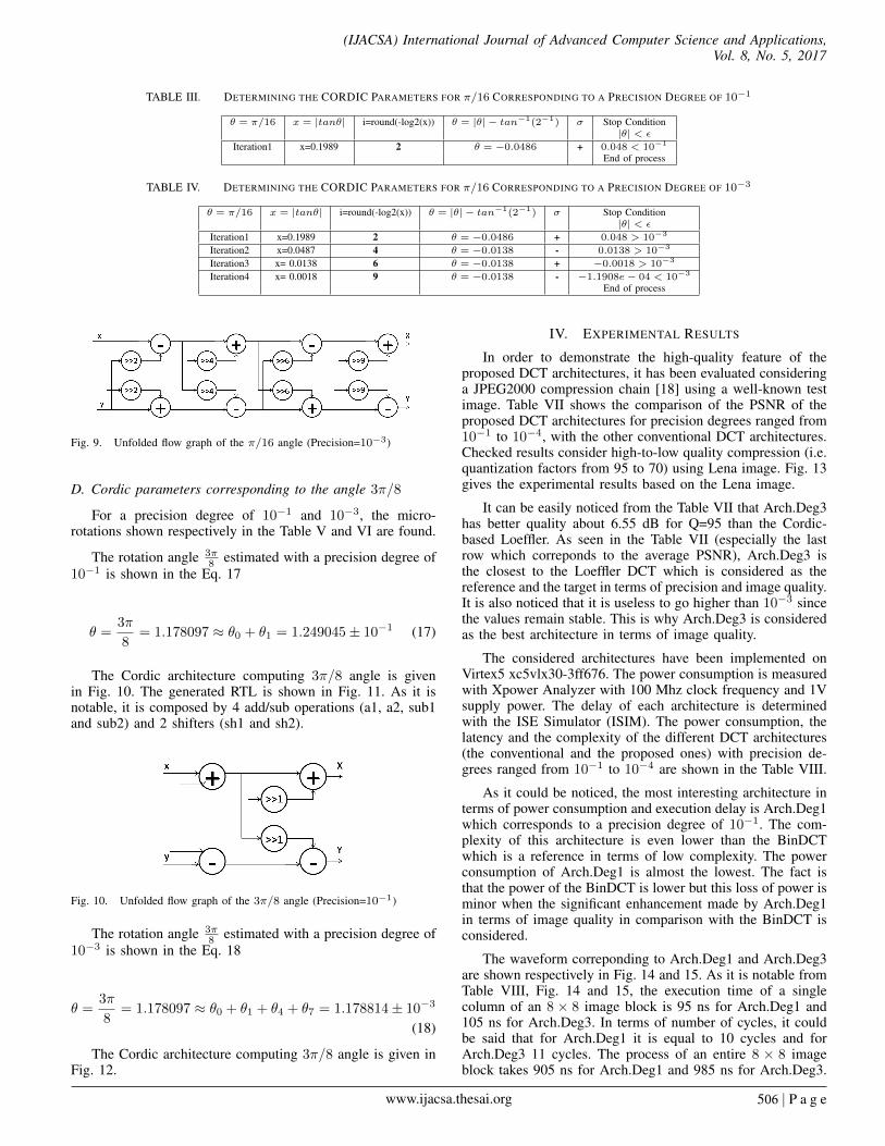
The Cordic architecture computing π/16 angle is given inFig. 7. The generated RTL is shown in Fig. 8. As it is shown,it consists on a subsystem with 2 inputs and 2 outputs. Thesubsystem is composed by two shift operators (sh1 and sh2)and two add/sub operators (a and sub).
Fig. 7. Unfolded flow graph of the π/16 angle (Precision=10−1)
Fig. 8. The generated RTL of the of the cordic π/16 (Precision=10−1)
The rotation angle π16 estimated with a precision degree of
10−3 is shown in the Eq. 16
θ =π
16= 0.196349 ≈ θ2 − θ4 + θ6 − θ9 = 0.196230± 10−3
(16)
The Cordic architecture computing π/16 angle is given inFig. 9.
www.ijacsa.thesai.org 505 | P a g e
(IJACSA) International Journal of Advanced Computer Science and Applications,Vol. 8, No. 5, 2017
TABLE III. DETERMINING THE CORDIC PARAMETERS FOR π/16 CORRESPONDING TO A PRECISION DEGREE OF 10−1
θ = π/16 x = |tanθ| i=round(-log2(x)) θ = |θ| − tan−1(2−1) σ Stop Condition|θ| < ε
Iteration1 x=0.1989 2 θ = −0.0486 + 0.048 < 10−1
End of process
TABLE IV. DETERMINING THE CORDIC PARAMETERS FOR π/16 CORRESPONDING TO A PRECISION DEGREE OF 10−3
θ = π/16 x = |tanθ| i=round(-log2(x)) θ = |θ| − tan−1(2−1) σ Stop Condition|θ| < ε
Iteration1 x=0.1989 2 θ = −0.0486 + 0.048 > 10−3
Iteration2 x=0.0487 4 θ = −0.0138 - 0.0138 > 10−3
Iteration3 x= 0.0138 6 θ = −0.0138 + −0.0018 > 10−3
Iteration4 x= 0.0018 9 θ = −0.0138 - −1.1908e− 04 < 10−3
End of process
Fig. 9. Unfolded flow graph of the π/16 angle (Precision=10−3)
D. Cordic parameters corresponding to the angle 3π/8
For a precision degree of 10−1 and 10−3, the micro-rotations shown respectively in the Table V and VI are found.
The rotation angle 3π8 estimated with a precision degree of
10−1 is shown in the Eq. 17
θ =3π
8= 1.178097 ≈ θ0 + θ1 = 1.249045± 10−1 (17)
The Cordic architecture computing 3π/8 angle is givenin Fig. 10. The generated RTL is shown in Fig. 11. As it isnotable, it is composed by 4 add/sub operations (a1, a2, sub1and sub2) and 2 shifters (sh1 and sh2).
Fig. 10. Unfolded flow graph of the 3π/8 angle (Precision=10−1)
The rotation angle 3π8 estimated with a precision degree of
10−3 is shown in the Eq. 18
θ =3π
8= 1.178097 ≈ θ0 + θ1 + θ4 + θ7 = 1.178814± 10−3
(18)
The Cordic architecture computing 3π/8 angle is given inFig. 12.
IV. EXPERIMENTAL RESULTS
In order to demonstrate the high-quality feature of theproposed DCT architectures, it has been evaluated consideringa JPEG2000 compression chain [18] using a well-known testimage. Table VII shows the comparison of the PSNR of theproposed DCT architectures for precision degrees ranged from10−1 to 10−4, with the other conventional DCT architectures.Checked results consider high-to-low quality compression (i.e.quantization factors from 95 to 70) using Lena image. Fig. 13gives the experimental results based on the Lena image.
It can be easily noticed from the Table VII that Arch.Deg3has better quality about 6.55 dB for Q=95 than the Cordic-based Loeffler. As seen in the Table VII (especially the lastrow which correponds to the average PSNR), Arch.Deg3 isthe closest to the Loeffler DCT which is considered as thereference and the target in terms of precision and image quality.It is also noticed that it is useless to go higher than 10−3 sincethe values remain stable. This is why Arch.Deg3 is consideredas the best architecture in terms of image quality.
The considered architectures have been implemented onVirtex5 xc5vlx30-3ff676. The power consumption is measuredwith Xpower Analyzer with 100 Mhz clock frequency and 1Vsupply power. The delay of each architecture is determinedwith the ISE Simulator (ISIM). The power consumption, thelatency and the complexity of the different DCT architectures(the conventional and the proposed ones) with precision de-grees ranged from 10−1 to 10−4 are shown in the Table VIII.
As it could be noticed, the most interesting architecture interms of power consumption and execution delay is Arch.Deg1which corresponds to a precision degree of 10−1. The com-plexity of this architecture is even lower than the BinDCTwhich is a reference in terms of low complexity. The powerconsumption of Arch.Deg1 is almost the lowest. The fact isthat the power of the BinDCT is lower but this loss of power isminor when the significant enhancement made by Arch.Deg1in terms of image quality in comparison with the BinDCT isconsidered.
The waveform correponding to Arch.Deg1 and Arch.Deg3are shown respectively in Fig. 14 and 15. As it is notable fromTable VIII, Fig. 14 and 15, the execution time of a singlecolumn of an 8 × 8 image block is 95 ns for Arch.Deg1 and105 ns for Arch.Deg3. In terms of number of cycles, it couldbe said that for Arch.Deg1 it is equal to 10 cycles and forArch.Deg3 11 cycles. The process of an entire 8 × 8 imageblock takes 905 ns for Arch.Deg1 and 985 ns for Arch.Deg3.
www.ijacsa.thesai.org 506 | P a g e

(IJACSA) International Journal of Advanced Computer Science and Applications,Vol. 8, No. 5, 2017
TABLE V. DETERMINING THE CORDIC PARAMETERS FOR 3π/8 CORRESPONDING TO A PRECISION DEGREE OF 10−1
θ = 3π/8 x = |tanθ| i=round(-log2(x)) θ = |θ| − tan−1(2−1) σ Stop Conditionπ/4 + π/8 |θ| < ε
Iteration1 x=1 0 θ = 0 - 0 < 0.1π/4 End of Process π/4
Iteration2 x=0.4142 1 θ = −0.0709 + 0.07 < 10−1
π/8 End of Process 3π/8
TABLE VI. DETERMINING THE CORDIC PARAMETERS FOR 3π/8 CORRESPONDING TO A PRECISION DEGREE OF 10−3
θ = 3π/8 x = |tanθ| i=round(-log2(x)) θ = |θ| − tan−1(2−1) σ Stop Conditionπ/4 + π/8 |θ| < ε
Iteration1 x=1 0 θ = 0 - 0 < 0.1π/4 End of Process π/4
Iteration2 x=0.4142 1 θ = −0.0709 + 0.07 > 10−3
π/8
Iteration3 x= 0.0711 4 θ = 0.0085 - 0.07 > 10−3
π/8
Iteration4 x=0.0085 7 θ = 7.1738e− 04 - 7.1738e− 04 < 10−3
π/8 End of Process π/8
xladdsub_cordic3pi8p1_4
sub1
a(29:0)
b(29:0)
c_in(0:0)
en(0:0)
rst(0:0)
ce
clk
clr
c_out(0:0)
s(30:0)
xladdsub_cordic3pi8p1_1
a1
a(29:0)
b(29:0)
c_in(0:0)
en(0:0)
rst(0:0)
ce
clk
clr
c_out(0:0)
s(30:0)
shift_a927339ac5
sh1
ip(30:0)
ce
clk
clr
op(30:0)
shift_a927339ac5
sh2
ip(30:0)
ce
clk
clr
op(30:0)
xladdsub_cordic3pi8p1_2
a2
a(30:0)
b(30:0)
c_in(0:0)
en(0:0)
rst(0:0)
ce
clk
clr
c_out(0:0)
s(31:0)
xladdsub_cordic3pi8p1_3
su2
a(30:0)
b(30:0)
c_in(0:0)
en(0:0)
rst(0:0)
ce
clk
clr
c_out(0:0)
s(31:0)
x3pi8_1_entity_9e283f8a5f:1
x3pi8_1_9e283f8a5f
in1(29:0)
in2(29:0)
ce_1
clk_1
out1(31:0)
out2(31:0)
cordic3pi8p1:1
cordic3pi8p1_x0
gateway_in(29:0)
gateway_in1(29:0)
ce_1
clk_1
gateway_out(31:0)
gateway_out1(31:0)
Fig. 11. The generated RTL of the of the cordic 3π/8 (Precision=10−1)
Fig. 12. Unfolded flow graph of the 3π/8 angle (Precision=10−3)
In terms of number of cycles, it could be said that Arch.Deg1takes 80 cycles and Arch.Deg3 88 cycles. This is perfectlynormal since Arch.Deg3 requires more shift/add operation
layers than Arch.Deg1. So the process takes more time.
In comparison with the Loeffler DCT, it could be saidthat Arch.Deg1 is somewhat slower since the multiplicationoperation is replaced by several layers of shift/add operatorswhich leads to a little higher delay.
If one compares the conventional Cordic Loeffler basedarchitecture, Arch.Deg1 and Arch.Deg2, he finds that the delayis the same even though the shift/add operation layers arenot exactly similar. This is perfectly normal since the delaydepends essentially on the longest path and in these three cases,the longest path passes through the 3π/16 Cordic.
www.ijacsa.thesai.org 507 | P a g e

(IJACSA) International Journal of Advanced Computer Science and Applications,Vol. 8, No. 5, 2017
TABLE VII. PSNR FROM HIGH-TO-LOW COMPRESSION QUALITY IN JPEG2000 FOR LENA128 IMAGE
Quality Loef. CLoef. BinDCT Arch.Deg1 Arch.Deg2 Arch.Deg3 Arch.Deg4Factor DCT DCT
95 44.23 36.98 26.94 41.33 42.04 43.53 43.5390 39.72 36.02 26.85 38.52 38.85 39.46 39.4685 37.14 35.11 26.78 36.44 36.62 36.99 36.9980 35.46 34.30 26.65 35.06 35.18 35.35 35.3575 34.36 33.71 26.57 34.03 34.12 34.28 34.2870 33.61 33.18 26.48 33.39 33.46 33.56 33.56
Average 37.42 34.88 26.71 36.46 36.71 37.19 37.19
(a) 34.28 dB for Q=75(Arch.Deg3)
(b) 36.99 dB for Q=85(Arch.Deg3)
(c) 43.53 dB for Q=95(Arch.Deg3)
(d) 36.98 dB for Q=95(Conventional CLDCT)
Fig. 13. Lena images obtained using the proposed Cordic-based Loeffler DCT for P = 10−3
TABLE VIII. COMPLEXITY AND POWER CONSUMPTION FOR DIFFERENT DCT ARCHITECTURES
8-point DCT Multipliers Add/Sub Shift Power(W) Delay(ns)Loeffler DCT[16] 11 29 0 0.744 75
CORDIC-based Loeffler DCT [14], [15] 0 38 16 0.642 95Bin DCT [17] 0 36 17 0.600 95
Arch.Deg1 (10−1) 0 34 12 0.630 95Arch.Deg2 (10−2) 0 40 18 0.640 95Arch.Deg3 (10−3) 0 46 24 0.656 105Arch.Deg4 (10−4) 0 52 30 0.659 115
Fig. 14. The Waveform corresponding to Arch.Deg1
www.ijacsa.thesai.org 508 | P a g e

(IJACSA) International Journal of Advanced Computer Science and Applications,Vol. 8, No. 5, 2017
Fig. 15. The Waveform corresponding to Arch.Deg3
V. CONCLUSION
In this paper, we present two optimal Cordic Loeffler basedDCT architectures: a high PSNR architecture (Arch.Deg3)and a fast and low power architecture (Arch.Deg1). TheCordic parameters required for these architectures have beencalculated using a MATLAB script. The obtained results con-cerning the first architecture (Arch.Deg3) show a significantimprovement in the PSNR (6,55 dB for Q=95 in comparisonwith the Cordic Loeffler based DCT and 16,6 dB for Q=95in comparison with the BinDCT) without a substantial lossof Power. Concerning the second architecture, we obtain anenhancement in terms of power consumption (12 mW incomparison with the conventional Cordic Loeffler based DCTand 114 mW in comparison with the Loeffler based DCT) witha significant improvement in terms of PSNR (4,35 dB for Q=95in comparison with the Cordic Loeffler based DCT and 14.4dB for Q=95 in comparison with the BinDCT). The optimalCordic Loeffler DCT architectures which we found could beused in biometrical systems and endoscopy applications.
REFERENCES
[1] N. Ahmed, T. Natarajan, and K. R. Rao, 'Discrete cosine transform',IEEE Transactions on Computers, vol. C-32, pp. 90-93, Jan. 1974.
[2] K. R. Rao and P. Yip, Discrete Cosine Transform Algorithms, Advan-tages, Applications, NewYork, NY, Academic Press, 1990
[3] Y. Y. Liu, H. X. Chen, Y. Zhao, H. Y. Sun, 'Discrete cosine transformoptimization in image compression based on genetic algorithm', 8thInternational Congress on Image and Signal Processing (CISP) (2015).
[4] Diego F.G. Coelho; Renato J. Cintra; Sunera Kulasekera; ArjunaMadanayake; Vassil S. Dimitrov'Error-free computation of 8-point dis-
crete cosine transform based on the Loeffler factorisation and algebraicintegers', IET Signal Processing, Volume 10, Issue 6, August 2016.
[5] J. Zhang, P. Chow, H. Liu, 'FPGA Implementation of Low-Powerand High-PSNR DCT/IDCT Architecture based on Adaptive RecodingCORDIC', International Conference on Field Programmable Technology(FPT) (2015).
[6] T.-T. Hoang ; H.-T. Nguyen ; X.-T. Nguyen ; C.-K. Pham ; D.-H. Le 'High-performance DCT architecture based on angle recodingCORDIC and Scale-Free Factor', IEEE Sixth International Conferenceon Communications and Electronics (ICCE), 2016
[7] M.-W. Lee, J.-H. Yoon and J. Park, 'Reconfigurable CORDIC-Based Low-Power DCT Architecture Based on Data Priority', IEEE Transactions onVery Large Scale Integration (VLSI) Systems, vol. 22, no. 5, pp. 1060-1068, 2014
[8] N. J. August and D. S. Ha, 'Low power design of DCT and IDCT forlow bit rate video codecs', IEEE Transactions on Multimedia, vol. 6, no.3, pp. 414422, June 2004.
[9] H. Jeong, J. Kim, and W. K. Cho, 'Low-power multiplierless DCTarchitecture using image correlation', IEEE Trans. Consumer Electron.,vol. 50, no. 1, pp. 262267, Feb. 2004
[10] P. K. Meher, J. Valls, T.-B. Juang, K. Sridharan, and K. Maharatna,'50 years of CORDIC: Algorithms, architectures and applications', IEEETransactions on Circuits and Systems I: Regular Papers, vol. 56, no. 9,pp. 18931907, Sep. 2009
[11] Y. Hachaıchi, and Y. Lahbib, 'An efficient mathematically correct scalefree CORDIC', 2016, Submitted, https://hal.archives-ouvertes.fr/hal-01327460.
[12] Neha K. Nawandar, Bharat Garg, G.K. Sharma 'RICO: A low powerRepetitive Iteration CORDIC for DSP applications in portable devices',Journal of Systems Architecture (2016)
[13] E. P. Mariatos , D. E. Metafas , J. A. Hallas and C. E. Goutis,'A fastDCT processor, based on special purpose CORDIC rotators', Proc. IEEEInt. Symp. Circuits Syst., vol. 4, pp. 271-274, 1994
[14] C.-C. Sun, S.-J. Ruan, B. Heyne, J. Goetze, 'Low-power and high quality
www.ijacsa.thesai.org 509 | P a g e

(IJACSA) International Journal of Advanced Computer Science and Applications,Vol. 8, No. 5, 2017
Cordic-based Loeffler DCT for signal processing', IET Circuits DevicesSyst., 1, (6), pp.453-461,2007.
[15] C.-C. Sun, P. Donner and J. Gtze, 'VLSI implementation of a config-urable IP Core for quantized discrete cosine and integer transforms',International Journal of Circuit Theory and Applications Volume 40,Issue 11, pages 11071126, November 2012.
[16] Loeffler, C., Lightenberg, A., and Moschytz, G.S., 'Practical fast 1-DDCT algorithms with 11-multiplications', Proc. ICASSP, Glasgow UK,vol. 2, pp. 988991,1989.
[17] Dang, P.P., Chau, P.M., Nguyen, T.Q., and Tran, T.D., (2005), 'BinDCTand its efficient VLSI architectures for real-time embedded applications',J. Image Sci. Technol., 49, (2), pp. 124-137.
[18] International Organization for Standardization. ITU-T RecommendationT.81. In ISO/IEC IS 10918-1, http://www.jpeg.org/jpeg/[ONLINE: March2017]
www.ijacsa.thesai.org 510 | P a g e


![AN EFFICIENT CORDIC PROCESSOR FOR COMPLEX DIGITAL … · CORDIC algorithm was first developed by Jack E. Volder in 1959 [1]. CORDIC algorithm is extremely useful in efficient and](https://static.fdocuments.us/doc/165x107/5e637e4912c3c2564c2cb16d/an-efficient-cordic-processor-for-complex-digital-cordic-algorithm-was-first-developed.jpg)