
VNR VIGNANA JYOTHI INSTITUTE OF … vignana jyothi institute of engineering & technology department...
43
VNR VIGNANA JYOTHI INSTITUTE OF ENGINEERING & TECHNOLOGY DEPARTMENT OF CIVIL ENGINEERING Academic plan : 2016- 2017 Class & Semester : III B.Tech - I Semester Branch : Civil Engineering Subject : Design of Reinforced Concrete Structures Subject Code : 13CED 016 Number of Weeks : 15 Number of Hours / week : 5 Number of periods planned : 65 Name of the Faculty : B.Narendra Kumar UNIT – I : INTRODUCTION SYLLABUS : Concepts of RC Design – Limit State design, Basic statistical principles, Characteristic strength, Partial load & safety factors, Representative stress-strain curves for cold worked deformed bars and mild steel bars, Assumptions in limit state design, Stress block parameters, IS .456 Codal provisions Beams Limit state design of Singly reinforced , Doubly reinforced , T and L beam sections. LEARNING OBJECTIVES : After completion of this unit, student will be able to Identify the various materials used in concrete List the various grades of concrete Identify the codal provisions of I.S. 456 – 2000 Describe the salient features of Limit State Method Draw stress-strain curves for cold worked deformed bars and mild steel bars. Analyse and design the singly reinforced beam sections Analyse and design the doubly reinforced beam sections Analyse and design the flanged ( T , L ) beam sections
-
Upload
vuonghuong -
Category
Documents
-
view
219 -
download
2
Transcript of VNR VIGNANA JYOTHI INSTITUTE OF … vignana jyothi institute of engineering & technology department...

VNR VIGNANA JYOTHI INSTITUTE OF ENGINEERING & TECHNOLOGY
DEPARTMENT OF CIVIL ENGINEERING
Academic plan : 2016- 2017
Class & Semester : III B.Tech - I Semester
Branch : Civil Engineering
Subject : Design of Reinforced Concrete Structures
Subject Code : 13CED 016
Number of Weeks : 15
Number of Hours / week : 5
Number of periods planned : 65
Name of the Faculty : B.Narendra Kumar
UNIT – I : INTRODUCTION
SYLLABUS :
Concepts of RC Design – Limit State design, Basic statistical principles,
Characteristic strength, Partial load & safety factors, Representative stress-strain
curves for cold worked deformed bars and mild steel bars, Assumptions in limit
state design, Stress block parameters, IS .456 Codal provisions
Beams Limit state design of Singly reinforced , Doubly reinforced , T and L beam
sections.
LEARNING OBJECTIVES :
After completion of this unit, student will be able to
Identify the various materials used in concrete
List the various grades of concrete
Identify the codal provisions of I.S. 456 – 2000
Describe the salient features of Limit State Method
Draw stress-strain curves for cold worked deformed bars and mild steel
bars.
Analyse and design the singly reinforced beam sections
Analyse and design the doubly reinforced beam sections
Analyse and design the flanged ( T , L ) beam sections

LECTURE PLAN :
Period
Description of topic No. of
Hrs.
Method of Teaching
1 Introduction 1 Black Board & PPT
2 Concepts of RC Design 1 Black Board & PPT
3 Salient features of Limit State Method 1 Black Board & PPT
4 Stress – Strain curves for Steel,
Concrete
1 Black Board & PPT
5 Terminology used in LSM, Stress
block parameters
1 Black Board & PPT
6 Recommendations of I.S. 456 – 2000 1 Black Board & PPT
7,8,9,10&11 Analysis & Design of Singly &
Doubly Reinforced beams
5 Black Board & Video
12,13,14,15 Analysis & Design of T beams
Sections
4 Black Board
& Video
16,17 Analysis & Design of L beams
Sections
2 Black Board
ASSIGNMENT :
1. What are the basic requirements of structural design ?
2. Explain the various stages in the design of an RCC structure
3. Sketch the stress – strain curves of Concrete, Mild steel and Cold worked
deformed bars
4. What are the important codal provisions in I.S. 456 – 2000
5. Design the flexural reinforcement for the rectangular concrete beam of size
250 mm x 400 mm simply supported on two masonry walls 230 mm thick and
6 m apart. The beam has to carry in addition to it’s own weight , a distributed
live load of 10 kN /m , dead load of 5 kN/m and a concentrated dead load of
30 kN placed at the midspan point. Assume that the beam is subjected to
moderate exposure condition. Use M 20 grade concrete and Fe 415 grade
steel.
6. Design a simply supported rectangular beam to carry 30 kN/m super imposed
load over a span of 6 m on 460 mm wide supports. Use M 20 grade concrete
and Fe 415 grade steel. Check the design for all necessary conditions.
7. A hall of internal dimensions 5 m x 15 m has beams spaced at 3 m c/c and a
slab of 120 mm thick. The beams are supported by walls around 300 mm
thick. Design the T – beams completely. Use M 25 grade concrete and Fe
415 grade steel.
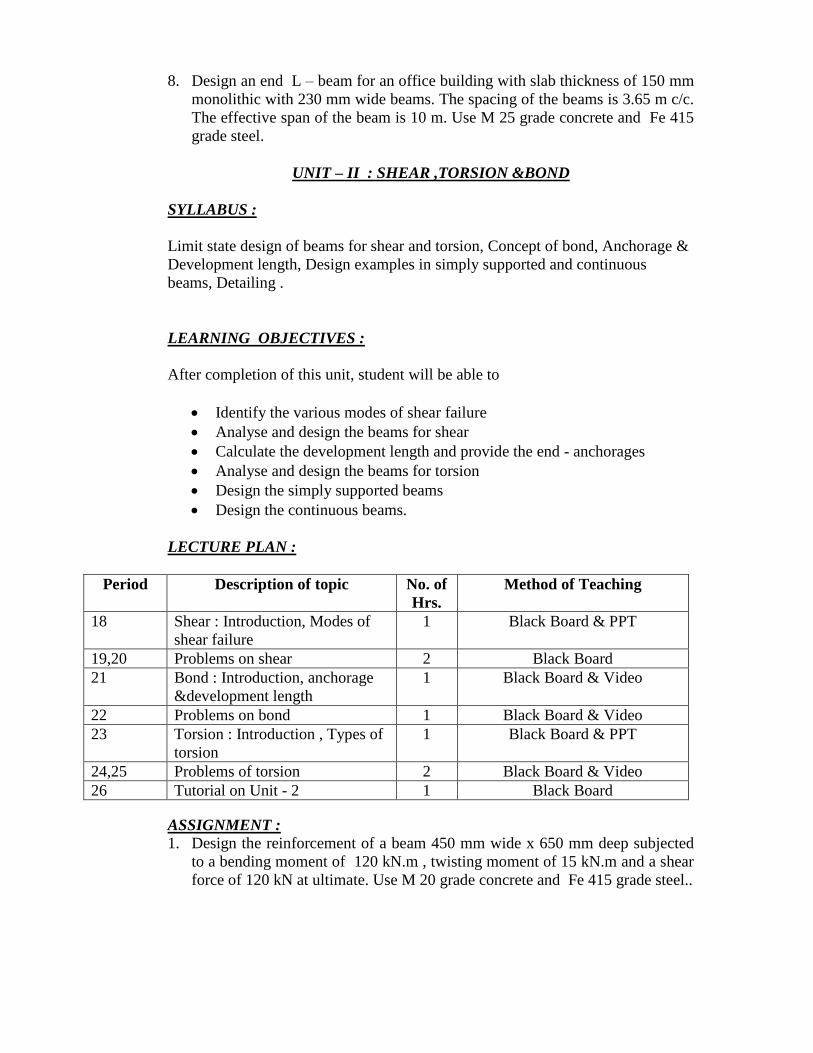
8. Design an end L – beam for an office building with slab thickness of 150 mm
monolithic with 230 mm wide beams. The spacing of the beams is 3.65 m c/c.
The effective span of the beam is 10 m. Use M 25 grade concrete and Fe 415
grade steel.
UNIT – II : SHEAR ,TORSION &BOND
SYLLABUS :
Limit state design of beams for shear and torsion, Concept of bond, Anchorage &
Development length, Design examples in simply supported and continuous
beams, Detailing .
LEARNING OBJECTIVES :
After completion of this unit, student will be able to
Identify the various modes of shear failure
Analyse and design the beams for shear
Calculate the development length and provide the end - anchorages
Analyse and design the beams for torsion
Design the simply supported beams
Design the continuous beams.
LECTURE PLAN :
Period Description of topic No. of
Hrs.
Method of Teaching
18 Shear : Introduction, Modes of
shear failure
1 Black Board & PPT
19,20 Problems on shear 2 Black Board
21 Bond : Introduction, anchorage
&development length
1 Black Board & Video
22 Problems on bond 1 Black Board & Video
23 Torsion : Introduction , Types of
torsion
1 Black Board & PPT
24,25 Problems of torsion 2 Black Board & Video
26 Tutorial on Unit - 2 1 Black Board
ASSIGNMENT :
1. Design the reinforcement of a beam 450 mm wide x 650 mm deep subjected
to a bending moment of 120 kN.m , twisting moment of 15 kN.m and a shear
force of 120 kN at ultimate. Use M 20 grade concrete and Fe 415 grade steel..
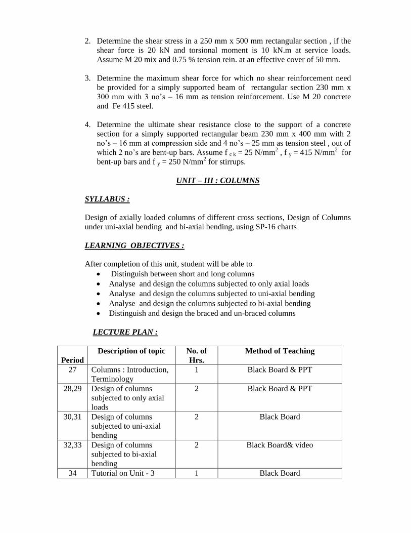
2. Determine the shear stress in a 250 mm x 500 mm rectangular section , if the
shear force is 20 kN and torsional moment is 10 kN.m at service loads.
Assume M 20 mix and 0.75 % tension rein. at an effective cover of 50 mm.
3. Determine the maximum shear force for which no shear reinforcement need
be provided for a simply supported beam of rectangular section 230 mm x
300 mm with 3 no’s – 16 mm as tension reinforcement. Use M 20 concrete
and Fe 415 steel.
4. Determine the ultimate shear resistance close to the support of a concrete
section for a simply supported rectangular beam 230 mm x 400 mm with 2
no’s – 16 mm at compression side and 4 no’s – 25 mm as tension steel , out of
which 2 no’s are bent-up bars. Assume f c k = 25 N/mm2 , f y = 415 N/mm
2 for
bent-up bars and f y = 250 N/mm2 for stirrups.
UNIT – III : COLUMNS
SYLLABUS :
Design of axially loaded columns of different cross sections, Design of Columns
under uni-axial bending and bi-axial bending, using SP-16 charts
LEARNING OBJECTIVES :
After completion of this unit, student will be able to
Distinguish between short and long columns
Analyse and design the columns subjected to only axial loads
Analyse and design the columns subjected to uni-axial bending
Analyse and design the columns subjected to bi-axial bending
Distinguish and design the braced and un-braced columns
LECTURE PLAN :
Period
Description of topic No. of
Hrs.
Method of Teaching
27 Columns : Introduction,
Terminology
1 Black Board & PPT
28,29 Design of columns
subjected to only axial
loads
2 Black Board & PPT
30,31 Design of columns
subjected to uni-axial
bending
2 Black Board
32,33 Design of columns
subjected to bi-axial
bending
2 Black Board& video
34 Tutorial on Unit - 3 1 Black Board

ASSIGNMENT :
1. A R.C.column rectangular in section 230 mm wide and 300 mm deep is
reinforced with 4 bars of 20 mm , one at each corner , with an effective cover
of 50 mm. It is subjected to an ultimate axial load of 340 kN , ultimate
bending moment of M u x = 30 kN.m. about x-axis bisecting the depth and
ultimate moment of M u y = 18 kN.m. about y-axis bisecting the width. Use
M 20 grade concrete and Fe 415 grade steel. Check the safety of the column.
2. Design an axially loaded tied column 400 mm x 400 mm pinned at both ends
with an unsupported length of 3 m for carrying a factored load of 2300 kN .
Use M 20 grade concrete and Fe 415 grade steel.
3. Calculate the ultimate strength in axial compression of a column 400 mm in
diameter and reinforced with 8 no’s -- 20 mm of grade Fe 415 , when the
column is helically reinforced by 8 mm bars at 55 mm pitch. Use M 20 grade
concrete.
UNIT – IV : FOOTINGS
SYLLABUS :
Different types of footings , Design of flat type and sloped type isolated Square ,
Rectangular and Circular footings.
LEARNING OBJECTIVES :
After completion of this unit, student must be able to
Identify various types of footings
Design the isolated flat square footings
Design the isolated flat rectangular footings
Design the isolated flat circular footings
Design the isolated sloped square footings
Design the isolated sloped rectangular footings
Design the isolated sloped circular footings
LECTURE PLAN :
Period Description of topic No. of Hrs. Method of Teaching
35 Footings : introduction , types
, codal provisions
1 Black Board & PPT
36,37 Design of isolated flat square
footings
2 Black Board & Video
38,39 Design of isolated flat
rectangular footings
2 Black Board & Video

40,41 Design of isolated flat circular
footings
2 Black Board & Video
42,43 Design of isolated sloped
square footings
2 Black Board & Video
44,45&
46
Design of isolated sloped
rectangular footings
3 Black Board & Video
47,48 Design of isolated sloped
circular footings
2 Black Board & Video
49 Tutorial on Unit - 4 1 Black Board
ASSIGNMENT :
1. Design an isolated footing for a rectangular column 300 mm x 450 mm
carrying an axial load of 1000 kN. The net bearing capacity of the soil is 120
kN/m2. Use M 20 grade concrete and Fe 415 grade steel.
2. Design an isolated circular footing for a square column of 500 mm diameter ,
transmitting a load of 900 kN to a soil having an allowable bearing capacity of
90 kN/m2. Use M 20 concrete and Fe 415 steel.
3. Design an isolated sloped footing for a rectangular column 300 mm x 450 mm
carrying an axial load of 1500 kN. The net bearing capacity of the soil is 150
kN/m2. Use M 25 grade concrete and Fe 415 grade steel.
4. Design an isolated sloped circular footing for a square column of 800 mm
diameter, transmitting a load of 1000 kN to a soil having an allowable bearing
capacity of 120 kN/m2. Use M 20 concrete and Fe 415 steel
UNIT –V : SLABS
SYLLABUS :
Design of one-way slabs, Design of Continuous slabs using IS coefficients,
Design of two-way simply supported and restrained slabs.
Limit state design for serviceability for Deflection and Cracking
LEARNING OBJECTIVES :
After completion of this unit, student must be able to
Distinguish between one-way slab and two-way slab
Design the one-way slabs
Design the two-way slabs
Know the significance of limit state of serviceability
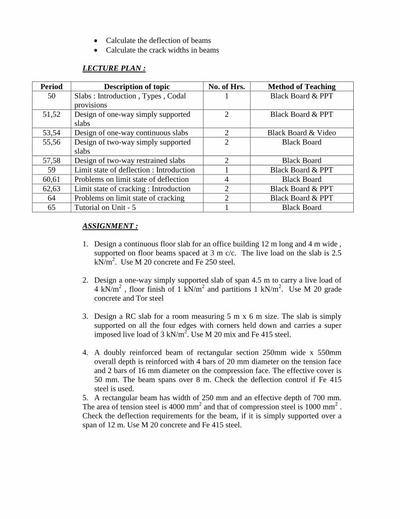
Calculate the deflection of beams
Calculate the crack widths in beams
LECTURE PLAN :
Period Description of topic No. of Hrs. Method of Teaching
50 Slabs : Introduction , Types , Codal
provisions
1 Black Board & PPT
51,52 Design of one-way simply supported
slabs
2 Black Board & PPT
53,54 Design of one-way continuous slabs 2 Black Board & Video
55,56 Design of two-way simply supported
slabs
2 Black Board
57,58 Design of two-way restrained slabs 2 Black Board
59 Limit state of deflection : Introduction 1 Black Board & PPT
60,61 Problems on limit state of deflection 4 Black Board
62,63 Limit state of cracking : Introduction 2 Black Board & PPT
64 Problems on limit state of cracking 2 Black Board & PPT
65 Tutorial on Unit - 5 1 Black Board
ASSIGNMENT :
1. Design a continuous floor slab for an office building 12 m long and 4 m wide ,
supported on floor beams spaced at 3 m c/c. The live load on the slab is 2.5
kN/m2. Use M 20 concrete and Fe 250 steel.
2. Design a one-way simply supported slab of span 4.5 m to carry a live load of
4 kN/m2 , floor finish of 1 kN/m
2 and partitions 1 kN/m
2. Use M 20 grade
concrete and Tor steel
3. Design a RC slab for a room measuring 5 m x 6 m size. The slab is simply
supported on all the four edges with corners held down and carries a super
imposed live load of 3 kN/m2. Use M 20 mix and Fe 415 steel.
4. A doubly reinforced beam of rectangular section 250mm wide x 550mm
overall depth is reinforced with 4 bars of 20 mm diameter on the tension face
and 2 bars of 16 mm diameter on the compression face. The effective cover is
50 mm. The beam spans over 8 m. Check the deflection control if Fe 415
steel is used.
5. A rectangular beam has width of 250 mm and an effective depth of 700 mm.
The area of tension steel is 4000 mm2 and that of compression steel is 1000 mm
2 .
Check the deflection requirements for the beam, if it is simply supported over a
span of 12 m. Use M 20 concrete and Fe 415 steel.

VNR VIGNANA JYOTHI INSTITUTE OF ENGINEERING & TECHNOLOGY
(Autonomous)
DEPARTMENT OF CIVIL ENGINEERING
III B. Tech, Ist Semester (Civil Engineering)
Subject : Irrigation Engineering
Subject Code : 13CED015
Academic Year : 2016 – 17
Number of working days : 90
Number of Hours / week : 4+1
Total number of periods planned: 65
Name of the Faculty Member: Dr. P. N. Singh
Course Objectives:
To define the fundamentals terminologies used in Irrigation Engineering.
To discuss the use of different kinds of Irrigation engineering components and its
design
To apply the Engineering Hydrology knowledge for the design of a irrigation system
To enable the students to design main components of a Irrigation System.
Course Outcomes (COs): Upon completion of this course, students should be able to:
CO-1: Identify different components of an irrigation system
CO-2: Describe different Irrigation engineering components and its design
CO-3: Practically apply the Engineering Hydrology knowledge in the design of an
irrigation system.
CO-4: Design main components of an Irrigation system
UNIT : I
Syllabus:
Introduction to Irrigation Engineering
Necessity and importance of irrigation, advantages and ill effects of irrigation, types of
irrigation, methods of application of irrigation water, Indian agricultural soils, methods of
improving soil fertility, preparation of land for irrigation, standards of quality for
irrigation water.
Water Requirements of Crops
Soil-water-plant relationship, vertical distribution of soil moisture, soil moisture
constants, soil moisture tension, consumptive use, estimation of consumptive use, Duty
and delta, factors affecting duty, depth and frequency of Irrigation, irrigation efficiencies.
Learning Objectives: After completion of the unit, the student will be able to:
Explain different aspects of irrigation
Explain various methods of irrigation
Calculate water requirement of crops
Calculate depth and frequency of irrigation, irrigation efficiencies
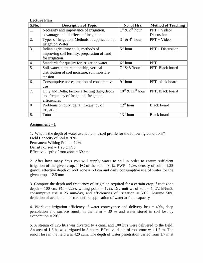
Lecture Plan
S.No. Description of Topic No. of Hrs. Method of Teaching
1. Necessity and importance of Irrigation,
advantage and ill effects of irrigation
1st & 2
nd hour PPT + Video+
Discussion
2. Types of Irrigation, Methods of application of
Irrigation Water
3rd
& 4th
hour PPT + Video
3. Indian agriculture soils, methods of
improving soil fertility, preparation of land
for irrigation
5th
hour PPT + Discussion
4. Standards for quality for irrigation water 6th
hour PPT
5. Soil-water-plant relationship, vertical
distribution of soil moisture, soil moisture
tension
7th
& 8th
hour PPT, Black board
6. Consumptive use estimation of consumptive
use
9th
hour PPT, black board
7. Duty and Delta, factors affecting duty, depth
and frequency of Irrigation, Irrigation
efficiencies
10th
& 11th
hour PPT, Black board
8 Problems on duty, delta , frequency of
irrigation
12th
hour Black board
8. Tutorial 13th
hour Black board
Assignment – 1
1. What is the depth of water available in a soil profile for the following conditions?
Field Capacity of Soil = 30%
Permanent Wilting Point = 12%
Density of soil = 1.25 gm/cc
Effective depth of root zone = 60 cm
2. After how many days you will supply water to soil in order to ensure sufficient
irrigation of the given crop, if FC of the soil = 30%, PWP =12%, density of soil = 1.25
gm/cc, effective depth of root zone = 60 cm and daily consumptive use of water for the
given crop =12.5 mm
3. Compute the depth and frequency of irrigation required for a certain crop if root zone
depth = 100 cm, FC = 22%, wilting point = 12%, Dry unit wt of soil = 14.72 kN/m3,
consumptive use = 25 mm/day, and efficiencies of irrigation = 50%. Assume 50%
depletion of available moisture before application of water at field capacity
4. Work out irrigation efficiency if water conveyance and delivery loss = 40%, deep
percolation and surface runoff in the farm = 30 % and water stored in soil lost by
evaporation = 20%
5. A stream of 125 lit/s was diverted to a canal and 100 lit/s were delivered to the field.
An area of 1.6 ha was irrigated in 8 hours. Effective depth of root zone was 1.7 m. The
runoff loss in the field was 420 cum. The depth of water penetration varied from 1.7 m at

the head end of the field to 1.3 m at the tail end. Available moisture holding capacity of
the soil is 20 cm per meter depth of soil. Determine water conveyance, water application,
water storage and water distribution efficiencies. The irrigation was stareted at moisture
extraction level of 50% of the available moisture.

UNIT : II
Syllabus:
Reservoir Planning
Factors governing selecting site for reservoirs, zones of storage of a reservoir, reservoir
yield, estimation of capacity of reservoir using mass curve. Reservoir sedimentation-
control.
Dams: Gravity Dams
Types of dams, factors affecting selection of type of dam, Forces acting on gravity dam,
causes of failure of a gravity dam, elementary profile and practical profile of a gravity
dam, limiting height of a low gravity dam, stability analysis, drainage galleries. .
Learning Objectives: After completion of the unit, the student will be able to:
Know about reservoir planning
Estimate the capacity of reservoir using mass curve
Explain about reservoir sedimentation control
Explain about types of dams and selection of dam type
Analyze the Forces acting on gravity dam and cause of failure of a gravity dam
Explain about the elementary profile and practical profile of a gravity dam
Perform the stability analysis on a gravity dam
Lecture Plan
S.No. Description of Topic No. of Hrs. Method of Teaching
1. Factors governing selecting site for
reservoirs, zones of storage of a reservoir,
reservoir yield
14th
hour PPT+Video
2. Estimation of capacity of reservoir using
mass curve, reservoir sedimentation control
15th
& 16th
hour PPT
3. Types of dams, factors affecting selection of
type of dam
17th
hour PPT
4. Forces acting on gravity dam, causes of
failure of a gravity dam
18th
hour PPT+ Black board
5. Elementary profile and practical profile of a
gravity dam, limiting height of a low gravity
dam
19th
, 20th
and
21st hour
PPT, Black board
6. Stability analysis, drainage galleries 22nd
& 23rd
hour PPT, Black board
7. Problems on Gravity Dams 24th
& 25th
hour Black board
8 Tutorial 26th
hour Black board
Assignment - 2
1. A reservoir had original storage capacity for 738 ha-m. The drainage area of the
reservoir is 80 sq km from which, annual sediment discharges into the reservoir at the
rate of 0.1153 ha-m per sq km of the drainage area. Assuming the trap efficiency is 80
percent, find the annual loss of the reservoir in per cent per year.
2. A concrete gravity dam has the following data:
Maximum Water level =297.00
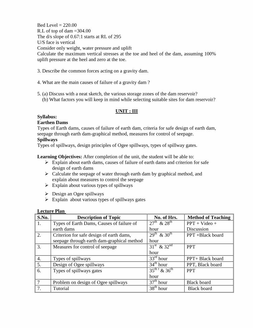
Bed Level = 220.00
R.L of top of dam =304.00
The d/s slope of 0.67:1 starts at RL of 295
U/S face is vertical
Consider only weight, water pressure and uplift
Calculate the maximum vertical stresses at the toe and heel of the dam, assuming 100%
uplift pressure at the heel and zero at the toe.
3. Describe the common forces acting on a gravity dam.
4. What are the main causes of failure of a gravity dam ?
5. (a) Discuss with a neat sketch, the various storage zones of the dam reservoir?
(b) What factors you will keep in mind while selecting suitable sites for dam reservoir?
UNIT : III
Syllabus:
Earthen Dams
Types of Earth dams, causes of failure of earth dam, criteria for safe design of earth dam,
seepage through earth dam-graphical method, measures for control of seepage.
Spillways
Types of spillways, design principles of Ogee spillways, types of spillway gates.
Learning Objectives: After completion of the unit, the student will be able to:
Explain about earth dams, causes of failure of earth dams and criterion for safe
design of earth dams
Calculate the seepage of water through earth dam by graphical method, and
explain about measures to control the seepage
Explain about various types of spillways
Design an Ogee spillways
Explain about various types of spillways gates
Lecture Plan
S.No. Description of Topic No. of Hrs. Method of Teaching
1. Types of Earth Dams, Causes of failure of
earth dams
27th
& 28th
hour
PPT + Video +
Discussion
2. Criterion for safe design of earth dams,
seepage through earth dam-graphical method
29th
& 30th
hour
PPT +Black board
3. Measures for control of seepage 31st & 32
nd
hour
PPT
4. Types of spillways 33rd
hour PPT+ Black board
5. Design of Ogee spillways 34th
hour PPT, Black board
6. Types of spillways gates 35th
t & 36
th
hour
PPT
7 Problem on design of Ogee spillways 37th
hour Black board
7. Tutorial 38th
hour Black board
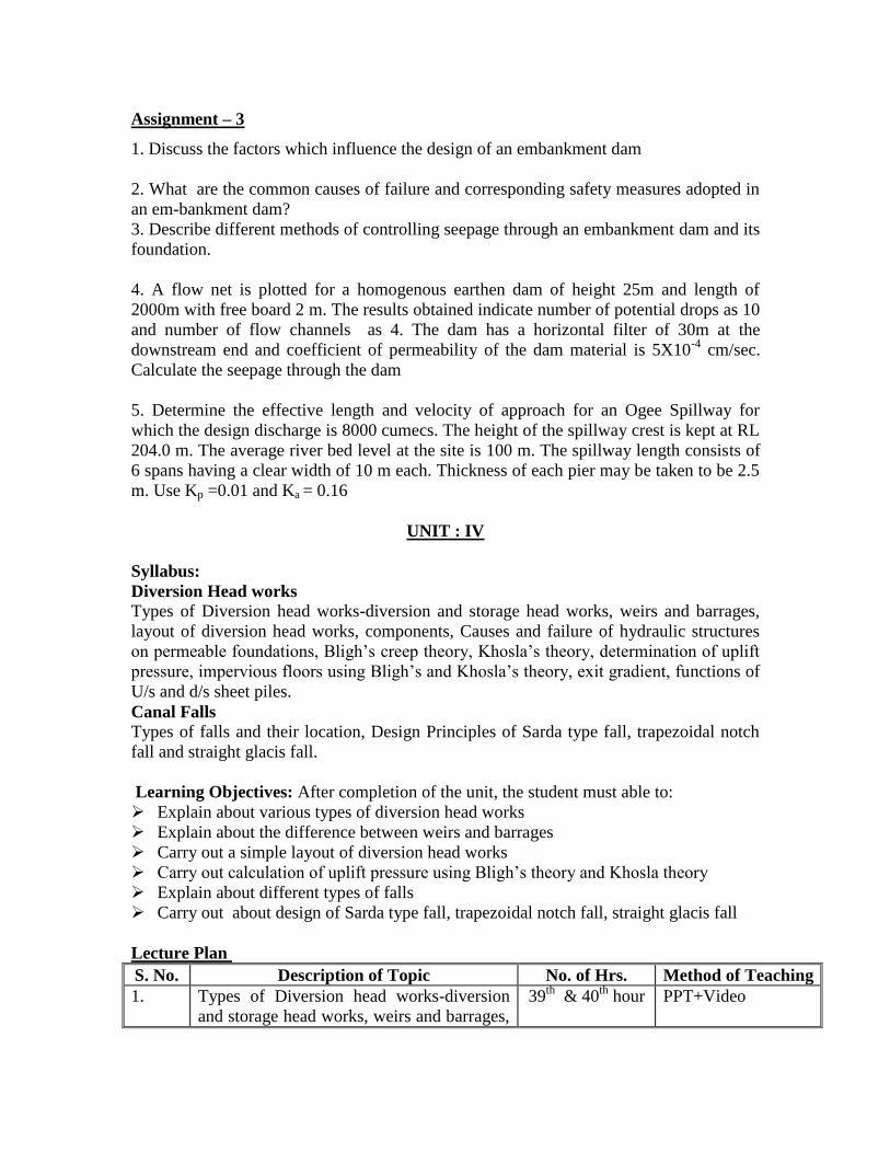
Assignment – 3
1. Discuss the factors which influence the design of an embankment dam
2. What are the common causes of failure and corresponding safety measures adopted in
an em-bankment dam?
3. Describe different methods of controlling seepage through an embankment dam and its
foundation.
4. A flow net is plotted for a homogenous earthen dam of height 25m and length of
2000m with free board 2 m. The results obtained indicate number of potential drops as 10
and number of flow channels as 4. The dam has a horizontal filter of 30m at the
downstream end and coefficient of permeability of the dam material is 5X10⁻⁴
cm/sec.
Calculate the seepage through the dam
5. Determine the effective length and velocity of approach for an Ogee Spillway for
which the design discharge is 8000 cumecs. The height of the spillway crest is kept at RL
204.0 m. The average river bed level at the site is 100 m. The spillway length consists of
6 spans having a clear width of 10 m each. Thickness of each pier may be taken to be 2.5
m. Use Kp =0.01 and Ka = 0.16
UNIT : IV
Syllabus:
Diversion Head works
Types of Diversion head works-diversion and storage head works, weirs and barrages,
layout of diversion head works, components, Causes and failure of hydraulic structures
on permeable foundations, Bligh’s creep theory, Khosla’s theory, determination of uplift
pressure, impervious floors using Bligh’s and Khosla’s theory, exit gradient, functions of
U/s and d/s sheet piles.
Canal Falls
Types of falls and their location, Design Principles of Sarda type fall, trapezoidal notch
fall and straight glacis fall.
Learning Objectives: After completion of the unit, the student must able to:
Explain about various types of diversion head works
Explain about the difference between weirs and barrages
Carry out a simple layout of diversion head works
Carry out calculation of uplift pressure using Bligh’s theory and Khosla theory
Explain about different types of falls
Carry out about design of Sarda type fall, trapezoidal notch fall, straight glacis fall
Lecture Plan
S. No. Description of Topic No. of Hrs. Method of Teaching
1. Types of Diversion head works-diversion
and storage head works, weirs and barrages,
39th
& 40th
hour PPT+Video
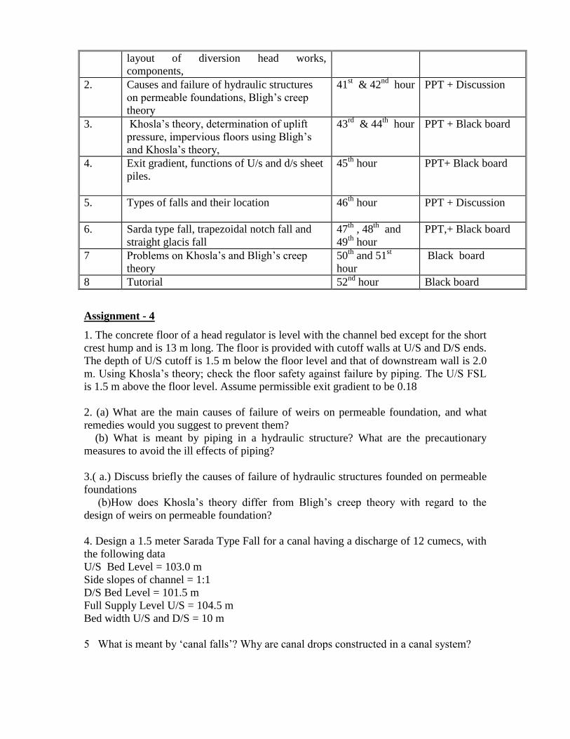
layout of diversion head works,
components,
2. Causes and failure of hydraulic structures
on permeable foundations, Bligh’s creep
theory
41st & 42
nd hour PPT + Discussion
3. Khosla’s theory, determination of uplift
pressure, impervious floors using Bligh’s
and Khosla’s theory,
43rd
& 44th
hour PPT + Black board
4. Exit gradient, functions of U/s and d/s sheet
piles.
45th
hour PPT+ Black board
5. Types of falls and their location
46th
hour PPT + Discussion
6. Sarda type fall, trapezoidal notch fall and
straight glacis fall
47th
, 48th
and
49th
hour
PPT,+ Black board
7 Problems on Khosla’s and Bligh’s creep
theory
50th
and 51st
hour
Black board
8 Tutorial 52nd
hour Black board
Assignment - 4
1. The concrete floor of a head regulator is level with the channel bed except for the short
crest hump and is 13 m long. The floor is provided with cutoff walls at U/S and D/S ends.
The depth of U/S cutoff is 1.5 m below the floor level and that of downstream wall is 2.0
m. Using Khosla’s theory; check the floor safety against failure by piping. The U/S FSL
is 1.5 m above the floor level. Assume permissible exit gradient to be 0.18
2. (a) What are the main causes of failure of weirs on permeable foundation, and what
remedies would you suggest to prevent them?
(b) What is meant by piping in a hydraulic structure? What are the precautionary
measures to avoid the ill effects of piping?
3.( a.) Discuss briefly the causes of failure of hydraulic structures founded on permeable
foundations
(b)How does Khosla’s theory differ from Bligh’s creep theory with regard to the
design of weirs on permeable foundation?
4. Design a 1.5 meter Sarada Type Fall for a canal having a discharge of 12 cumecs, with
the following data
U/S Bed Level = 103.0 m
Side slopes of channel = 1:1
D/S Bed Level = 101.5 m
Full Supply Level U/S = 104.5 m
Bed width U/S and D/S = 10 m
5 What is meant by ‘canal falls’? Why are canal drops constructed in a canal system?
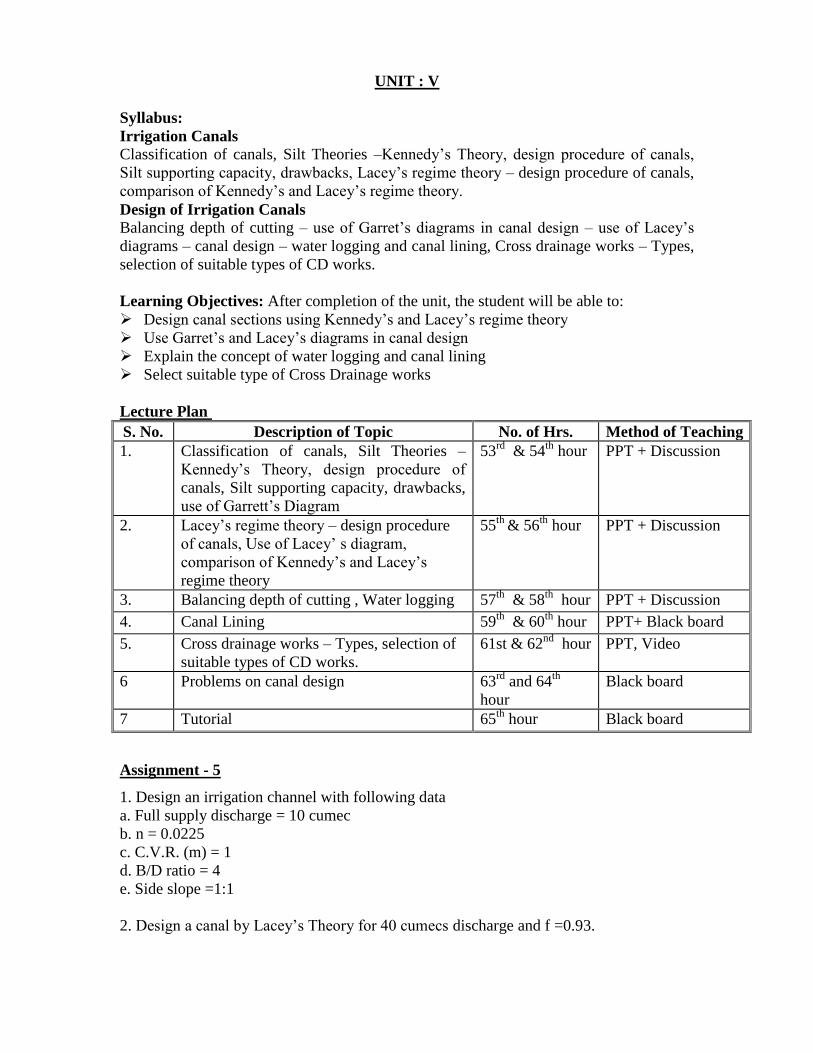
UNIT : V
Syllabus:
Irrigation Canals
Classification of canals, Silt Theories –Kennedy’s Theory, design procedure of canals,
Silt supporting capacity, drawbacks, Lacey’s regime theory – design procedure of canals,
comparison of Kennedy’s and Lacey’s regime theory.
Design of Irrigation Canals
Balancing depth of cutting – use of Garret’s diagrams in canal design – use of Lacey’s
diagrams – canal design – water logging and canal lining, Cross drainage works – Types,
selection of suitable types of CD works.
Learning Objectives: After completion of the unit, the student will be able to:
Design canal sections using Kennedy’s and Lacey’s regime theory
Use Garret’s and Lacey’s diagrams in canal design
Explain the concept of water logging and canal lining
Select suitable type of Cross Drainage works
Lecture Plan
S. No. Description of Topic No. of Hrs. Method of Teaching
1. Classification of canals, Silt Theories –
Kennedy’s Theory, design procedure of
canals, Silt supporting capacity, drawbacks,
use of Garrett’s Diagram
53rd
& 54th
hour PPT + Discussion
2. Lacey’s regime theory – design procedure
of canals, Use of Lacey’ s diagram,
comparison of Kennedy’s and Lacey’s
regime theory
55th
& 56th
hour PPT + Discussion
3. Balancing depth of cutting , Water logging 57th
& 58th
hour PPT + Discussion
4. Canal Lining 59th
& 60th
hour PPT+ Black board
5. Cross drainage works – Types, selection of
suitable types of CD works.
61st & 62nd
hour PPT, Video
6 Problems on canal design 63rd
and 64th
hour
Black board
7 Tutorial 65th
hour Black board
Assignment - 5
1. Design an irrigation channel with following data
a. Full supply discharge = 10 cumec
b. n = 0.0225
c. C.V.R. (m) = 1
d. B/D ratio = 4
e. Side slope =1:1
2. Design a canal by Lacey’s Theory for 40 cumecs discharge and f =0.93.
3. (a) Draw a typical canal cross section which is partly constructed in cutting and partly
in filling. Discuss briefly its various components, such as: side slopes, berms, banks,
service road, dowla, spoil banks etc
(b) What is meant by balancing depth and how it is determined?
4. Design a concrete lined channel to carry a discharge of 350 cumecs at slope of 1:5000.
Side slope is 1.5: 1, n = 0.014. Assume limiting velocity as 2 m/s
5 What are the different types of cross drainage works that are necessary on a canal
alignment? State briefly the conditions under which each one is used
TEXT BOOKS
1. Irrigation Engineering and Hydraulic Structures by S.K. Garg (Khanna
Publishers)
2. Irrigation Engineering by K.R. Arora (Standard Publishers)
3. Irrigation Engineering by R.K. Sharma and T.K. Sharma (S.Chand Publishers)
REFERENCES
1. Irrigation and Water Resources Engineering by G.L.Asawa (New Age Publishers)
2. Concrete Dams by Varshney
3. Theory and Design of Hydraulic Structures by Varshney (Gupta & Gupta).
VNR VIGNANA JYOTHI INSTITUTE OF ENGINEERING & TECHNOLOGY
(Autonomous)
DEPARTMENT OF CIVIL ENGINEERING
III B. Tech, Ist Semester (Civil Engineering)
Subject : Engineering Geology
Subject Code : 13CED017
Academic Year : 2016 – 17
Number of working days : 90
Number of Hours / week : 3 + 1
Total number of periods planned: 56
Name of the Faculty Member: P.Arti Sudam
Course Objectives: Student will be able to
Know geology from Civil Engineering point of view
Understand Mineral and rock properties
Understand the significance of structural geology
Understand the concepts of Geophysical methods
Course Outcomes (COs): Upon completion of this course, students should be able to:
CO-1: Define geology and its importance in Civil Engineering
CO-2: List different properties of Minerals
CO-3: Classify the rocks
CO-4: Acquire the knowledge of structural geology.
UNIT : I
Syllabus:
Introduction: Definition of Geology, Engineering Geology. Importance of Geology
from Civil Engineering point of view. Importance of physical geology, petrology and
structural geology. Case studies of failures of few Civil Engineering constructions.
Weathering of rocks and its effect on the properties of rocks, importance of weathering
with reference to dams, reservoirs and tunnels.
Learning Objectives: After completion of the unit, the student must able to:
Importance of Engineering Geology for Civil Engineers.
Briefly write historical case studies where civil engineering structures failed due lack
of knowledge during planning and construction.
Briefly write importance of petrology and structural geology for civil engineers.
Write how weathering effects granite which influences performance of dams,
reservoirs and tunnels.
Lecture Plan
S.No. Description of Topic No. of Hrs. Method of Teaching
1. Introduction, Definition of Geology,
Engineering Geology
1sthour Black board + Video
2. Importance of Geology from Civil
Engineering point of view.
2nd
hour PPT + Video
3. Importance of physical geology, petrology
and structural geology.
3rd
hour Black board
4. Case studies of failures of few Civil
Engineering constructions
4th
hour Black board + Video
5. Weathering of rocks and its effect on the
properties of rocks,
5th
& 6th
hours Black board
6. Importance of weathering with reference to
dams, reservoirs and tunnels.
7th
& 8th
hours Black board + PPT
Assignment – 1
1. Write short notes on
(a) Effect of weathering on physical properties of Rocks.
(b) Importance of weathering with reference to dams, reservoirs and tunnels.
2. Briefly write case histories of some Civil Engineering constructions due to
geological draw backs.
UNIT : II
Syllabus:
Mineralogy: Definition of mineral, mineralogy, Importance of study of minerals: rock
forming and ore is forming minerals. Different methods of study of minerals.Advantages
of study of minerals by physical identification method. Physical properties of minerals
for identification of minerals. Physical properties of following minerals: Feldspar,
Quartz, Flint, Jasper, Olivine, Augite, Hornblende, Muscovite, Biotite, Asbestos,
Chlorite, Kyanite, Garnet, Talc, Calcite. Study of ore forming minerals such as Pyrite,
Hematite, Magnetite, Amethyst, Galena, Pyrolusite, Graphite,Magnesite and Bauxite,
Coral reefs.
Learning Objectives: After completion of the unit, the student must able to:
Write importance of study of minerals.
Write important physical properties of various rock forming and economically
important minerals.
Lecture Plan
S.No. Description of Topic No. of Hrs. Method of Teaching
1. Introduction to Mineralogy 9th
hour PPT + Video
2. Definition of mineral, Importance of study of
minerals
10th
hours Black board
3. Different methods of study of minerals 11th
hour Black board + Video
4. Advantages of study of minerals, by physical
properties
12th
hours Black board
5. Role of study of physical properties of
minerals in the identification of minerals
13th
hour Black board
6. Study of physical properties of rock forming
minerals: Feldspar and Quartz.
14th
hour Black board + PPT
7. Study of physical properties of rock forming
minerals: Flint, Jasper, Olivine, Augite.
15th
hour Black board
8. Study of physical properties of rock forming
minerals: Hornblende, Muscovite, Biotite,
Asbestos.
16th
hour Black board + Video
9. Study of physical properties of rock forming
minerals: Chlorite, Kyanite, Garnet, Talc
17th
hour Black board
10. Study of other common economic minerals
such as Calcite, Pyrite, Hematite, Magnetite,
Chlorite.
18th
hour Black board
11. Study of other common economic minerals
such as, Magnetite, Chlorite. Galena,.
19th
hour Black board + PPT
12. Study of other common economic minerals
such as Pyrolusite, Graphite, Magnesite and
Bauxite.
20th
hour Black board + PPT
13. Some other minerals study.- Tutorial I
21sthour Black board + PPT
Assignment - 2
1. Write definition of mineral and state importance of study of minerals
2 What is the role of study of physical properties of minerals in the identification of
minerals ?
3. Write the important properties of Pyrite, Hematite, Magnetite, Chrorite, Galena,
Pyrolusite, Graphite, Magnesite and Bauxite
UNIT : III
Syllabus:
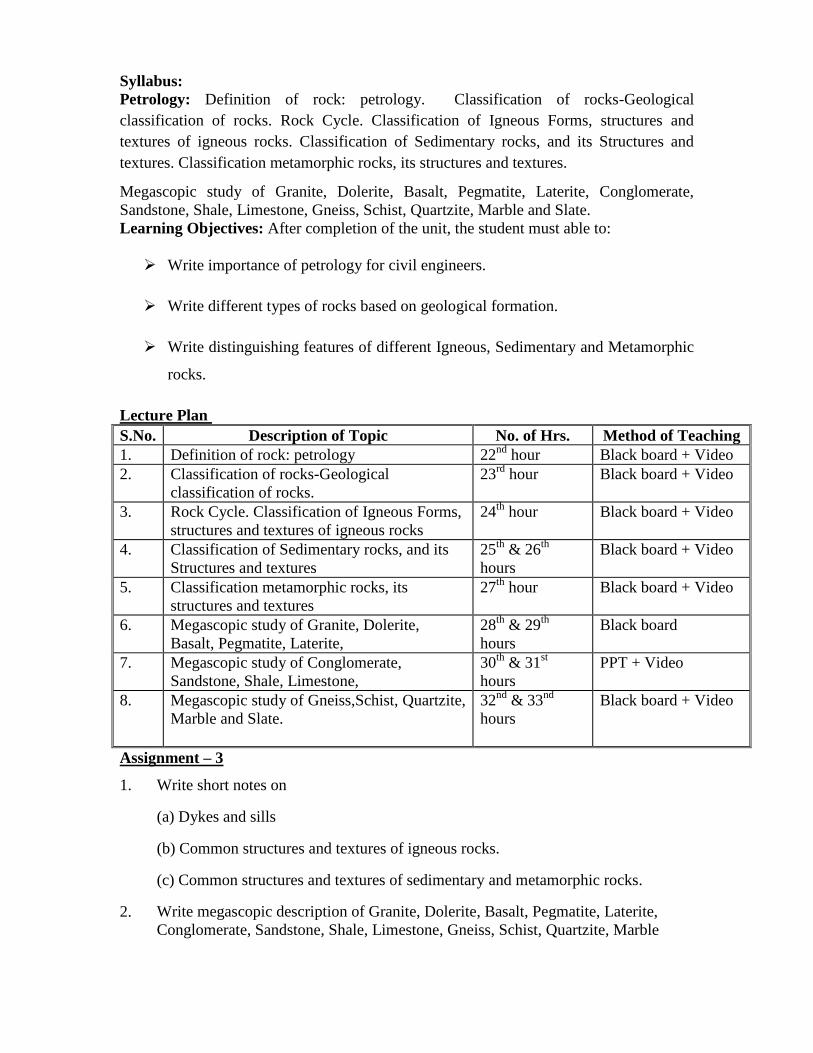
Petrology: Definition of rock: petrology. Classification of rocks-Geological
classification of rocks. Rock Cycle. Classification of Igneous Forms, structures and
textures of igneous rocks. Classification of Sedimentary rocks, and its Structures and
textures. Classification metamorphic rocks, its structures and textures.
Megascopic study of Granite, Dolerite, Basalt, Pegmatite, Laterite, Conglomerate,
Sandstone, Shale, Limestone, Gneiss, Schist, Quartzite, Marble and Slate.
Learning Objectives: After completion of the unit, the student must able to:
Write importance of petrology for civil engineers.
Write different types of rocks based on geological formation.
Write distinguishing features of different Igneous, Sedimentary and Metamorphic
rocks.
Lecture Plan
S.No. Description of Topic No. of Hrs. Method of Teaching
1. Definition of rock: petrology 22nd
hour Black board + Video
2. Classification of rocks-Geological
classification of rocks.
23rd
hour Black board + Video
3. Rock Cycle. Classification of Igneous Forms,
structures and textures of igneous rocks
24th
hour Black board + Video
4. Classification of Sedimentary rocks, and its
Structures and textures
25th
& 26th
hours
Black board + Video
5. Classification metamorphic rocks, its
structures and textures
27th
hour Black board + Video
6. Megascopic study of Granite, Dolerite,
Basalt, Pegmatite, Laterite,
28th
& 29th
hours
Black board
7. Megascopic study of Conglomerate,
Sandstone, Shale, Limestone,
30th
& 31st
hours
PPT + Video
8. Megascopic study of Gneiss,Schist, Quartzite,
Marble and Slate.
32nd
& 33nd
hours
Black board + Video
Assignment – 3
1. Write short notes on
(a) Dykes and sills
(b) Common structures and textures of igneous rocks.
(c) Common structures and textures of sedimentary and metamorphic rocks.
2. Write megascopic description of Granite, Dolerite, Basalt, Pegmatite, Laterite,
Conglomerate, Sandstone, Shale, Limestone, Gneiss, Schist, Quartzite, Marble
and Slate
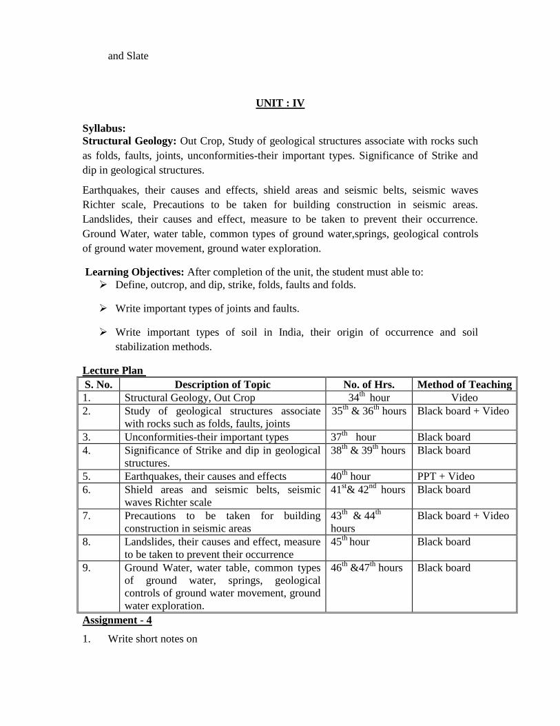
UNIT : IV
Syllabus:
Structural Geology: Out Crop, Study of geological structures associate with rocks such
as folds, faults, joints, unconformities-their important types. Significance of Strike and
dip in geological structures.
Earthquakes, their causes and effects, shield areas and seismic belts, seismic waves
Richter scale, Precautions to be taken for building construction in seismic areas.
Landslides, their causes and effect, measure to be taken to prevent their occurrence.
Ground Water, water table, common types of ground water,springs, geological controls
of ground water movement, ground water exploration.
Learning Objectives: After completion of the unit, the student must able to:
Define, outcrop, and dip, strike, folds, faults and folds.
Write important types of joints and faults.
Write important types of soil in India, their origin of occurrence and soil
stabilization methods.
Lecture Plan
S. No. Description of Topic No. of Hrs. Method of Teaching
1. Structural Geology, Out Crop 34th
hour Video
2. Study of geological structures associate
with rocks such as folds, faults, joints
35th
& 36th
hours Black board + Video
3. Unconformities-their important types 37th
hour Black board
4. Significance of Strike and dip in geological
structures.
38th
& 39th
hours Black board
5. Earthquakes, their causes and effects 40th
hour PPT + Video
6. Shield areas and seismic belts, seismic
waves Richter scale
41st& 42
nd hours Black board
7. Precautions to be taken for building
construction in seismic areas
43th
& 44th
hours
Black board + Video
8. Landslides, their causes and effect, measure
to be taken to prevent their occurrence
45th
hour Black board
9. Ground Water, water table, common types
of ground water, springs, geological
controls of ground water movement, ground
water exploration.
46th
&47th
hours Black board
Assignment - 4
1. Write short notes on
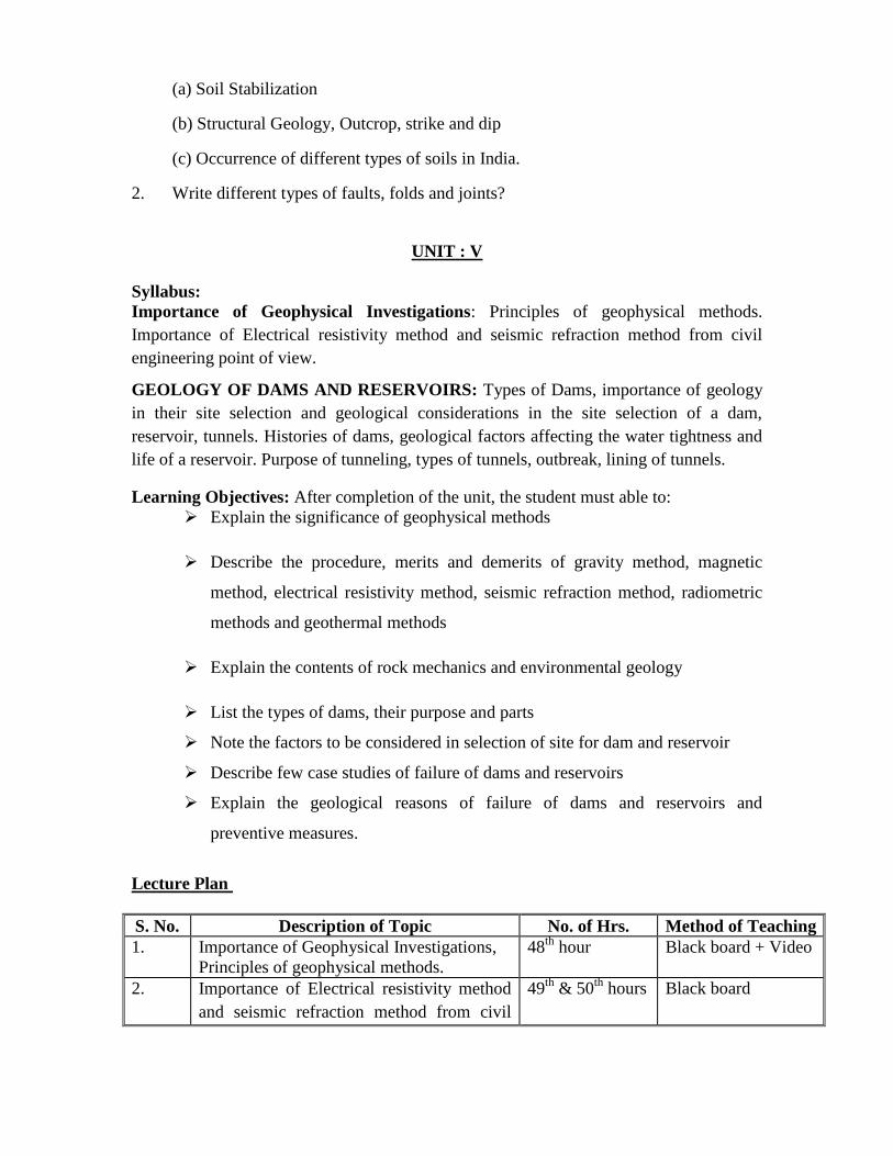
(a) Soil Stabilization
(b) Structural Geology, Outcrop, strike and dip
(c) Occurrence of different types of soils in India.
2. Write different types of faults, folds and joints?
UNIT : V
Syllabus:
Importance of Geophysical Investigations: Principles of geophysical methods.
Importance of Electrical resistivity method and seismic refraction method from civil
engineering point of view.
GEOLOGY OF DAMS AND RESERVOIRS: Types of Dams, importance of geology
in their site selection and geological considerations in the site selection of a dam,
reservoir, tunnels. Histories of dams, geological factors affecting the water tightness and
life of a reservoir. Purpose of tunneling, types of tunnels, outbreak, lining of tunnels.
Learning Objectives: After completion of the unit, the student must able to:
Explain the significance of geophysical methods
Describe the procedure, merits and demerits of gravity method, magnetic
method, electrical resistivity method, seismic refraction method, radiometric
methods and geothermal methods
Explain the contents of rock mechanics and environmental geology
List the types of dams, their purpose and parts
Note the factors to be considered in selection of site for dam and reservoir
Describe few case studies of failure of dams and reservoirs
Explain the geological reasons of failure of dams and reservoirs and
preventive measures.
Lecture Plan
S. No. Description of Topic No. of Hrs. Method of Teaching
1. Importance of Geophysical Investigations,
Principles of geophysical methods.
48th
hour Black board + Video
2. Importance of Electrical resistivity method
and seismic refraction method from civil
49th
& 50th
hours Black board

engineering point of view.
3. Geology of dams and reservoirs: types of
dams,
51st & 52
nd hours Video
4. Importance of geology in their site selection
and geological considerations in the site
selection of a dam, reservoir, tunnels.
53rd
&54th
hours Black board
6. Histories of dams, geological factors
affecting the water tightness and life of a
reservoir.
55th
hour Black board + Video
7. Purpose of tunneling, types of tunnels,
outbreak, lining of tunnels
56th
hour Black board + PPT
Assignment - 5
1. Write short notes on grouting, design, types of solutions used
2. Describe the following geophysical methods
a) Gravity method
b) Magnetic method
c) Radio metric method
d) Geothermal method
3. Explain the geological factors to be considered for the selection of reservoir site
4. Describe two case studies of failure of reservoir
5. Write a note on the preventive measures for failure of reservoir
6. Describe the following geophysical methods
e) Gravity method
f) Magnetic method
g) Radio metric method
h) Geothermal method
7. Explain the geological factors to be considered for the selection of reservoir site
8. Describe two case studies of failure of reservoir
9. Write a note on the preventive measures for failure of reservoir
TEXT BOOKS
1. Engineering Geology by N.Chennakesavulu,Mc-Millan, India Ltd.
2. Principals of Engineering Geology by K.V.G.K. Gokhale, B.S publications
3. Fundamentals of Engineering Geology by F.G Bell, Butterworth’s publications,New
Delhi.
REFERENCES
1. Engineering Geology by Parbin Singh.
2. Engineering Geology by Venkat Reddy.
3. Engineering Geology :Rock in Engineering construction by Richard E.Goodman.

VNR VIGNANA JYOTHI INSTITUTE OF ENGINEERING & TECHNOLOGY
DEPARTMENT OF CIVIL ENGINEERING
III B. Tech (Civil Engineering), I – Semester
Subject : Geotechnical Engineering-I
Subject Code : 13 CED018
Academic Year : 2016- –2017
Number of Working days : 90
Number of Hours / week : 4
Total number of periods planned: 64
Name of the Faculty Member : K. Suresh.
Course Objectives
To create an ability to apply knowledge of geotechnical engineering
To accentuate the understanding of the basic principles of soil mechanics and its
applications to solve problems related to geotechnical engineering.
To improve the basic understanding of the index and engineering properties of
soil
To improve the concepts to understanding the hydraulic behavior of the soil
Course Outcomes (COs): Upon completion of this course, students should be able to:
CO-1 An ability to identify, formulate and solve geotechnical engineering
problems.
CO-2 Improvising techniques, skills, and modern engineering tools necessary for
understanding in geotechnical engineering practice.
CO-3 complete awareness of the classical concept of soil mechanics and its
necessity.
CO-4 An awareness of the selection of soil based on the applicability and
requirement conditions.
Syllabus:
Unit - I
Properties of Soil
Historical development – Physical properties of Soil – Void ratio – Porosity, Degree of
Saturation, Water content, Unit Weights, Specific Gravity – their relationships, Relative
density. Consistency limits – determination and various indices – plasticity index
Liquidity index – Significance and Importance, Activity. Classifications : Mechanical
analysis – Sieve analysis, stoke’s law, hydrometer Analysis Textural Classification,
Structural Classification based on size – unified soil classification and modification by
Bureau of Indian Standard. Basics of clay minerals mineralogy
Learning Objectives: After completion of the unit, the student must able to:
Learning Objectives
After completion of unit students should be able to:
Explain the formation of soil and different types of soils on the earth.
Define various terms as Void ratio. Porosity, degree of saturation, water content,
densities, unit weights, specific gravity and their inter-relationships.
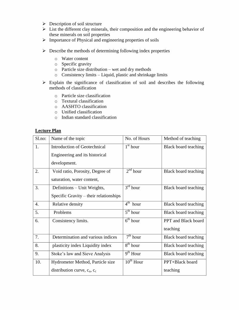
Description of soil structure
List the different clay minerals, their composition and the engineering behavior of
these minerals on soil properties
Importance of Physical and engineering properties of soils
Describe the methods of determining following index properties
o Water content
o Specific gravity
o Particle size distribution – wet and dry methods
o Consistency limits – Liquid, plastic and shrinkage limits
Explain the significance of classification of soil and describes the following
methods of classification
o Particle size classification
o Textural classification
o AASHTO classification
o Unified classification
o Indian standard classification
Lecture Plan
Sl.no: Name of the topic No. of Hours Method of teaching
1. Introduction of Geotechnical
Engineering and its historical
development.
1st hour Black board teaching
2. Void ratio, Porosity, Degree of
saturation, water content,
2nd
hour Black board teaching
3. Definitions – Unit Weights,
Specific Gravity – their relationships
3rd
hour Black board teaching
4. Relative density 4th
hour Black board teaching
5. Problems 5th
hour Black board teaching
6. Consistency limits. 6th
hour PPT and Black board
teaching
7. Determination and various indices 7th
hour Black board teaching
8. plasticity index Liquidity index 8th
hour Black board teaching
9. Stoke’s law and Sieve Analysis 9th
Hour Black board teaching
10. Hydrometer Method, Particle size
distribution curve, cu, cc
10th
Hour PPT+Black board
teaching
11. Textural classification 11th
hour Black board teaching
12. Structural classification based on
size.
12th
hour Black board teaching
13. Unified soil classification. 13th
hour PPT and Black board
teaching
14. Clay minerals mineralogy 14th
hour Black board teaching
Tutorial problems & questions
1. A soil sample has a bulk unit weight of 21.5kN/cu.m and degree of saturation is 85%.
Determine the void ratio, porosity and water content if the specific gravity of solids is
2.67
2. A saturated soil mass has a porosity of 40% and specific gravity of 2.65. Determine i)
water content ii) Dry density iii) Saturated unit weight
3. A saturated sample of soil has a water content of 30%. Assuming G=2.70, calculate
dry unit weight, saturated density and submerged unit weight.
4. The maximum and minimum dry unit weights of sand, determined in the laboratory,
are 2g/cc (20kN/m3) and 1.5g/cc (15kN/m
3) respectively. If the relative density of sand is
74%, determine the insitu porosity of sand deposit. Assume G=2.6
Assignment- 1
1. In a three phase soil system, derive the relationship between the degree of saturation Sr,
mass unit weight γ, water content w, specific gravity of soil grains G and unit weight of
water γw
2. Explain the terms: Void ratio, porosity, degree of saturation, air content, and
percentage of air voids
3. Soil A has kaolonite mineral as its major constituent. Soil B has montmorillonite as its
major constituent which soil is likely to have higher liquid limit. Which soil is likely to
shrink more?
4. Explain the significance and development of electrical double layer around a clay
particle.
5. How clay minerals are formed? Indicate their structure and properties. Explain relative
density and thxiotropy
6. Define soil texture and soil structure. What are the various terms used to describe the
above properties of the soil?
UNIT - II Permeability and Seepage
Soil water-types, Darcy’s law-Factors affecting permeability, Determination of
permeability by constant head and falling head method as per IS – 2720, field test as per
IS – 5529 (part I)- pumping in test and pumping out test. Permeability of layered soils
Seepage forces, General flow equation (Laplace equation). Flow net construction and
applications, anisotropic soil conditions, quick sand condition. Uplift pressure, exit
gradient, failure due to piping, Criteria for design of filters.
Learning Objectives
After completion of unit students should be able to:
Explain different types of soil water
Define capillarity and derivation of expression for capillary rise
State the terminology related to capillarity and factors affecting it.
Explain Darcy’s law and its validity
Definition of coefficient of permeability and factors effecting it
Laboratory and field determination of coefficient of permeability
Explain Confined and Unconfined aquifers, discharge calculation etc.
Lecture Plan
Sl.no: Name of the topic No of Hours Method of teaching
15. Darcy’s law-Factors affecting
permeability
15th
hour Black board
teaching and PPT
16. Determination of permeability 16th
hour Black board
teaching and PPT
17. Permeability by constant head and
falling head method.
17th
hour PPT and Black
board teaching
18. Pumping in test and pumping out
test.
18th
hour Black board
teaching
19. Permeability of layered soils
Seepage forces
19th
hour Black board
teaching
20. General flow equation 20th
hour Black board
teaching
21. Flow net construction and
applications
21st hour Black board
teaching and PPT
22. Anisotropic soil conditions, quick
sand condition
22nd
hour Black board
teaching
23. Uplift pressure, exit gradient, failure 23rd
hour PPT and Black
due to piping. board teaching
24. Criteria for design of filters. 24th
hour Black board
teaching
Tutorial problems & questions
1. What are the different types of soil water? Discuss
2. The following data pertains to the coefficients of permeability of a stratified soil
deposit.
Soil K (mm/sec) Thickness of stratum (m)
A 0.87 x 10⁻³
3.20
B 1.8 x 10⁻⁴
3.95
C 3.5 x 10⁻⁵
4.86
Determine the ratio of coefficients of horizontal permeability to the vertical permeability
3. For what type of soil do you prefer the falling head test and variable head test? Why
Assignment-2
1. Define Darcy’s law. If K1, K2, K3 are the permeabilities of layers h1, h2, and h3
thick, derive the formulae to find equivalent permeability in the horizontal and vertical
directions.
2. Explain the double packer method for determining permeability of field soils. Explain
the method of determining the coefficient of permeability of soil from the field pumping
out test.
3. In a falling head test the following results were obtained:
Length of specimen = 350mm
Diameter of stand pipe = 20mm
Diameter of sample = 100mm
Head at starting of test = 1200mm
Time elapsed = 345 sec
Coefficient of permeability = 0.03mm/sec
Find the height at which the test is terminated.
4. Mention the two laboratory methods for determining the coefficient of permeability
5. Write short notes on factors permeability
UNIT – III Compaction:
Compaction-Factors affecting compaction. Dry density and moisture content relationship.
Zero air voids line. Engineering behavior of compacted soils. Standard Proctor test and
Modified Proctor test as per IS – 2720. Field compaction equipment, Field control of
compaction.
Consolidation: primary compression and secondary compression determination of
preconsolidation pressure. Normally consolidated, over consolidated and under
consolidated clays. Oedometer Test, e-p and e-log p curves – compression index,
coefficient of compressibility and coefficient of volume decrease. Terzaghi’s one
dimensional consolidation theory assumption, derivation and application, coefficient of
consolidation time curve fitting methods, initial compression.
Learning Objectives
After completion of unit students should be able to:
Define compaction and the two laboratory test to determine the maximum dry
density and optimum moisture content
Explain the factors affecting compaction and types of compaction adopted in field
Describe Proctor needle
Explain the procedure to maintain control on compaction
Describe the phenomenon of consolidation and how it varies from compaction
Explain the different terms related to consolidation
State the laboratory procedure for determination coefficient of consolidation and
compression index
Describe the procedure for calculation of magnitude of settlement and time rate of
consolidation
Lecture Plan
Sl.no: Name of the topic No of hours Method of teaching
25. Compaction-Factors affecting
compaction
25th
hour Black board
teaching
26 Dry density and moisture content
relationship
26th
hour Black board
teaching
27. Zero air voids line. 27th
hour Black board
teaching
28. Engineering behavior of compacted
soils
28th
hour Black board
teaching
29. Standard Proctor test and Modified
Proctor test as per IS-2720
29th
hour PPT and Black
board teaching
30. Field compaction equipment, Field
control of compaction
30th
hour Black board
teaching
31. Problems 31st hour Black board
teaching
32. Problems 32nd
hour Black board
teaching
33. primary compression and secondary 33rd
hour Black board
compression determination of pre
consolidation Pressure.
teaching
34. Normally consolidated, over
consolidated and under consolidated
clays
34th
hour Black board
teaching
35. Oedometer Test 35th
hour PPT and Black
board teaching
36. e-p and e-log p curves 36th
hour Black board
teaching
37. compression index, coefficient of
compressibility and coefficient of
volume decrease
37th
hour Black board
teaching
38. Terzaghi’s one dimensional
consolidation theory assumption
38th
hour Black board
teaching
39. Terzaghi’s one dimensional
Derivation and application
39th
hour Black board
teaching
40. coefficient of consolidation 40th
hour Black board
teaching
41. Time curve fitting methods, initial
compression
41st hour Black board
teaching
42. Problems. 42nd
hour Black board
teaching
Tutorial problems & questions
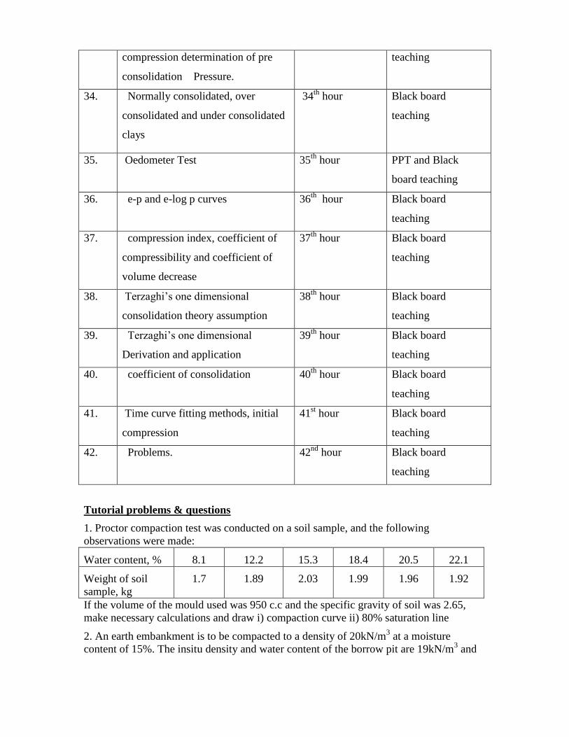
1. Proctor compaction test was conducted on a soil sample, and the following
observations were made:
Water content, % 8.1 12.2 15.3 18.4 20.5 22.1
Weight of soil
sample, kg
1.7 1.89 2.03 1.99 1.96 1.92
If the volume of the mould used was 950 c.c and the specific gravity of soil was 2.65,
make necessary calculations and draw i) compaction curve ii) 80% saturation line
2. An earth embankment is to be compacted to a density of 20kN/m3 at a moisture
content of 15%. The insitu density and water content of the borrow pit are 19kN/m3 and
8% respectively. How much excavation should be carried out from the borrow pit for
each m of the embankment?
3. Derive the expression for zero air void line and draw the line for a specific gravity of
2.67
4. The water table in a lake has been lowered by 22m below the bed, will this cause a
settlement of a clay layer 6m thick, lying 28m below the bed level? Explain.
5. An oedometer test is performed on a 2cm thick clay sample. After 5mintes, 50%
consolidation is reached. After how long a time would the same degree of consolidation
be achieved in the field where the layer have the same drainage conditions (double
drainage).
6. Distinguish between the normally consolidated and over consolidated soils.
7. Explain in detail the two methods for determining the coefficient of consolidation of
soil.
8. The void ratio of clay is 1.64, and its compression index is found to be 0.8 at a pressure
of 190 kN/m2. What will the void ratio if the pressure in increased to 250 kN/m
2
Assignment-3
1. Explain the factors effecting compaction.
2. Differentiate between i) standard Proctor compaction test ii) Modified Proctor test
Draw an ideal ‘compaction curve’ and discuss the effect of moisture content on the dry
density
3. What is the effect of compaction on engineering properties of soil?
4. What are the types of rollers used for compacting different types of soils in the field?
Write a note on “Proctor’s needle”
5. Define: (i) Compression index (ii) Coefficient of volume decrease (iii) Coefficient of
consolidation (iv) percent consolidation
6. Obtain the differential equation defining the one dimensional consolidation as given by
Terzaghi.
7. Explain the difference between compaction and consolidation.
8. A normally consolidated clay layer of 10m thickness has a unit weight of 20 kN/m3
and specific gravity
2.72. The liquid limit of the clay is 58%. A structure is constructed on this clay increase
the overburden by 10%. Estimate the ultimate consolidation settlement. There is no
secondary compression.
UNIT - IV Stress Distribution in Soils Effective stress concept, Nature of effective stresses, Effect of water table fluctuations on
effective stress, Effective stress in a soil mass under hydro static condition, capillarity
effect on effective stress. Effective stress under steady seepage condition, failure of
structures by piping. Boussinesq theory- point load, line load, strip load, circular and
rectangular loaded areas. Pressure distribution diagram on a horizontal and vertical plane,
pressure bulb, Westergaard's theory, equivalent point load method, Newmark chart,
Fadum chart, contact pressure, approximate stress distribution method.
Learning Objectives
After completion of unit students should be able to:
Derive expression for the vertical stress at various points below the ground
surface due following types of foundation loads
o Concentrated load
o Line load
o Strip load
o Rectangular and
o Circular load
Explain the procedure for calculation of vertical stress due to any load by
Neumark’s Influence chart
State the Westergaard’s theory for calculation of stresses
Sl.no: Name of the topic No of hours Method of teaching
43. Effective stress concept 43rd
hour Black board
teaching
44. Nature of effective stresses, Effect
of water table fluctuations on
effective stress
44th
hour Black board
teaching
45. Effective stress in a soil mass under
hydro static condition
45th
hour Black board
teaching
46. capillarity effect on effective stress 46th
hour Black board
teaching
47. Effective stress under steady
seepage condition
47th
hour Black board
teaching
48. failure of structures by piping 48th
hour Black board
teaching
49. Boussinesq theory- point load. 49th
hour Black board
teaching
50. Line load, strip load, circular and
rectangular loaded areas
50th
hour Black board
teaching and PPT
51. pressure distribution diagram on a
horizontal and vertical plane
51st hour Black board
teaching
52. pressure bulb, Westergaard's theory,
equivalent point load method,
52nd
hour Black board
teaching
53. Newmark chart, Fadum chart 53rd
hour Black board
teaching
54. contact pressure, approximate stress
distribution method.
54th
hour Black board
teaching
55. Problems. 55th
hour Black board
teaching
UNIT - V Shear Strength of Soil
Stress strain curve, stress at a point-Mohr circle of stress, Mohr-coulomb failure
criteria, pore pressure, total and effective stress. Peak and residual shear strength.
Factors affecting shear strength. Laboratory measurement of shear strength by direct,
unconfined, Vane shear test and triaxial tests under different drainage conditions.
Shear strength characteristics of sands. Sensitivity and thixotropy of cohesive soils.
Shear strength of sands, critical void ratio and dilatancy, shear strength of clays, total
stress analysis and effective stress analysis,
Learning Objectives:
After completion of unit students should be able to:
Define total stress, pore water pressure and effective stress, explain the effect of
Capillarity, Steady seepage and Hydro dynamic conditions
Explain Laplace Theory and Describe the methods of plotting flow net
State the theory and uses of flow nets
Calculate the quantity of discharge, loss of head etc. due to seepage of water.
Design the graded filter
Sl.no: Name of the topic No of hours Method of teaching
56. Stress strain curve, stress at a point-
Mohr circle of stress, Mohr-coulomb
failure criteria
56th
hour Black board
teaching
57. Total and effective stress. Peak and
residual shear strength
57th
hour Black board
teaching
58. Laboratory measurement of shear
strength by direct, unconfined, Vane
shear test
58th
hour Black board
teaching
59. Triaxial tests under different
drainage conditions.
59th
hour Black board
teaching
60. Shear strength characteristics of
sands. Sensitivity
60th
hour Black board
teaching
61. Thixotropy of cohesive soils. Shear
strength of sands Critical void ratio
and dilatancy, shear strength of
clays, total stress analysis and
effective stress Analysis,
61st hour Black board
teaching
62. Problems. 62nd
hour Black board
teaching
63 Problems 63rd
hour Black board
teaching
64 Problems 64th
hour Black board
teaching
Tutorial problems & questions
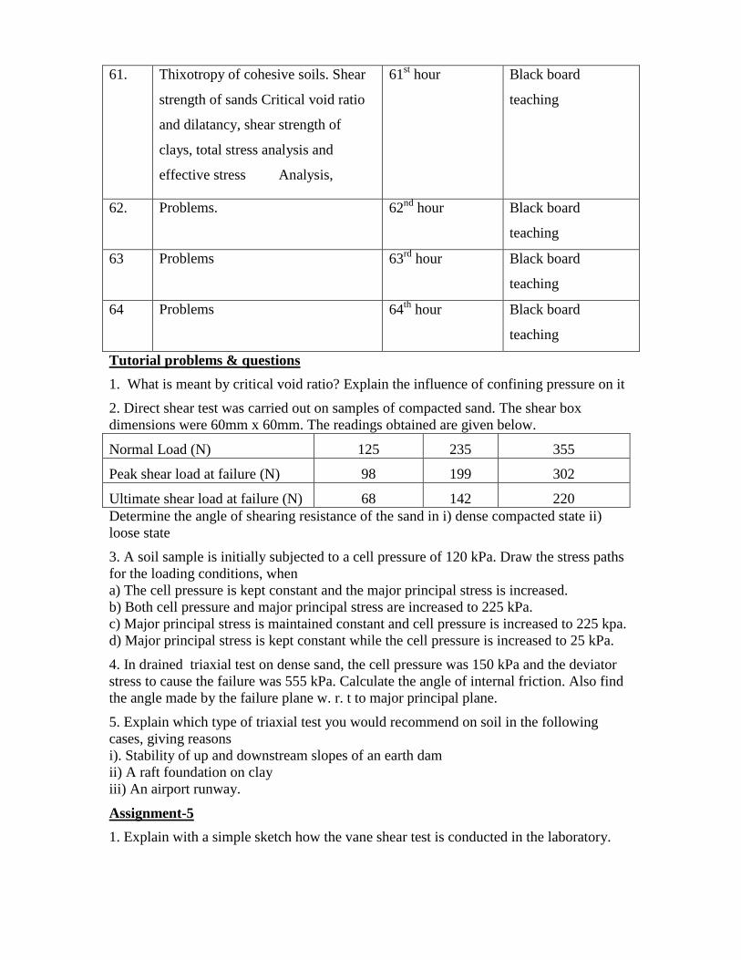
1. What is meant by critical void ratio? Explain the influence of confining pressure on it
2. Direct shear test was carried out on samples of compacted sand. The shear box
dimensions were 60mm x 60mm. The readings obtained are given below.
Normal Load (N) 125 235 355
Peak shear load at failure (N) 98 199 302
Ultimate shear load at failure (N) 68 142 220
Determine the angle of shearing resistance of the sand in i) dense compacted state ii)
loose state
3. A soil sample is initially subjected to a cell pressure of 120 kPa. Draw the stress paths
for the loading conditions, when
a) The cell pressure is kept constant and the major principal stress is increased.
b) Both cell pressure and major principal stress are increased to 225 kPa.
c) Major principal stress is maintained constant and cell pressure is increased to 225 kpa.
d) Major principal stress is kept constant while the cell pressure is increased to 25 kPa.
4. In drained triaxial test on dense sand, the cell pressure was 150 kPa and the deviator
stress to cause the failure was 555 kPa. Calculate the angle of internal friction. Also find
the angle made by the failure plane w. r. t to major principal plane.
5. Explain which type of triaxial test you would recommend on soil in the following
cases, giving reasons
i). Stability of up and downstream slopes of an earth dam
ii) A raft foundation on clay
iii) An airport runway.
Assignment-5
1. Explain with a simple sketch how the vane shear test is conducted in the laboratory.

2. A laboratory vane shear test was conducted on a soft saturated clayey soil sample. The
diameter and height of vane are 10mm and 15mm respectively. Find the shear strength of
the sample if it failed under a torque of 80 N.mm was applied. Derive the equation used,
if any.
3. A purely cohesive sample of cohesion 25 kpa is subjected to a cell pressure of 100 kPa
in a triaxial test. Will the sample fail? Why?
4. Keeping the minor principal stress constant as 200 kPa, the major principal stress on a
cylindrical soil sample was increased till the failure occurred. If the cohesion and angle of
internal friction of the soil were 250 kPa and 25◦ respectively, calculate (i) maximum
axial stress at failure (ii) Shear and normal stress along the failure plane (iii) the angle of
inclination of the failure plane.
5. Explain the difference in the methods of running undrained, consolidated undrained
and drained tests in triaxial test set up.
6. A cylindrical soil specimen of saturated clay, 38 mm in diameter and 80mm in height
was tested in an unconfined compression testing machine. Find the unconfined
compressive strength, if the specimen failed under an axial load of 250 N when the axial
deformation was 12mm. Also compute the value of apparent cohesion and angle of
internal friction of the soil if the angle made by the failure plane with horizontal was
recorded as 50◦.
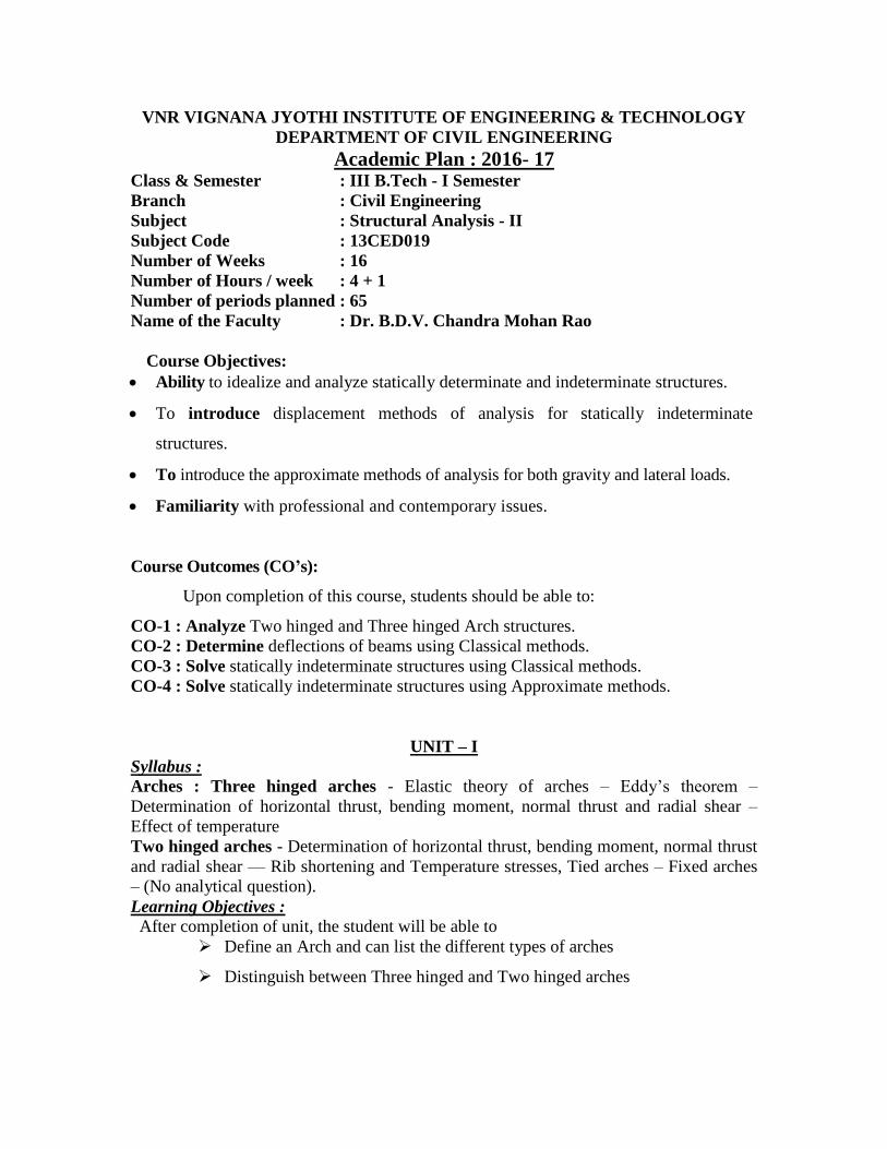
VNR VIGNANA JYOTHI INSTITUTE OF ENGINEERING & TECHNOLOGY
DEPARTMENT OF CIVIL ENGINEERING
Academic Plan : 2016- 17 Class & Semester : III B.Tech - I Semester
Branch : Civil Engineering
Subject : Structural Analysis - II
Subject Code : 13CED019
Number of Weeks : 16
Number of Hours / week : 4 + 1
Number of periods planned : 65
Name of the Faculty : Dr. B.D.V. Chandra Mohan Rao
Course Objectives:
Ability to idealize and analyze statically determinate and indeterminate structures.
To introduce displacement methods of analysis for statically indeterminate
structures.
To introduce the approximate methods of analysis for both gravity and lateral loads.
Familiarity with professional and contemporary issues.
Course Outcomes (CO’s):
Upon completion of this course, students should be able to:
CO-1 : Analyze Two hinged and Three hinged Arch structures.
CO-2 : Determine deflections of beams using Classical methods.
CO-3 : Solve statically indeterminate structures using Classical methods.
CO-4 : Solve statically indeterminate structures using Approximate methods.
UNIT – I
Syllabus :
Arches : Three hinged arches - Elastic theory of arches – Eddy’s theorem –
Determination of horizontal thrust, bending moment, normal thrust and radial shear –
Effect of temperature
Two hinged arches - Determination of horizontal thrust, bending moment, normal thrust
and radial shear –– Rib shortening and Temperature stresses, Tied arches – Fixed arches
– (No analytical question).
Learning Objectives :
After completion of unit, the student will be able to
Define an Arch and can list the different types of arches
Distinguish between Three hinged and Two hinged arches
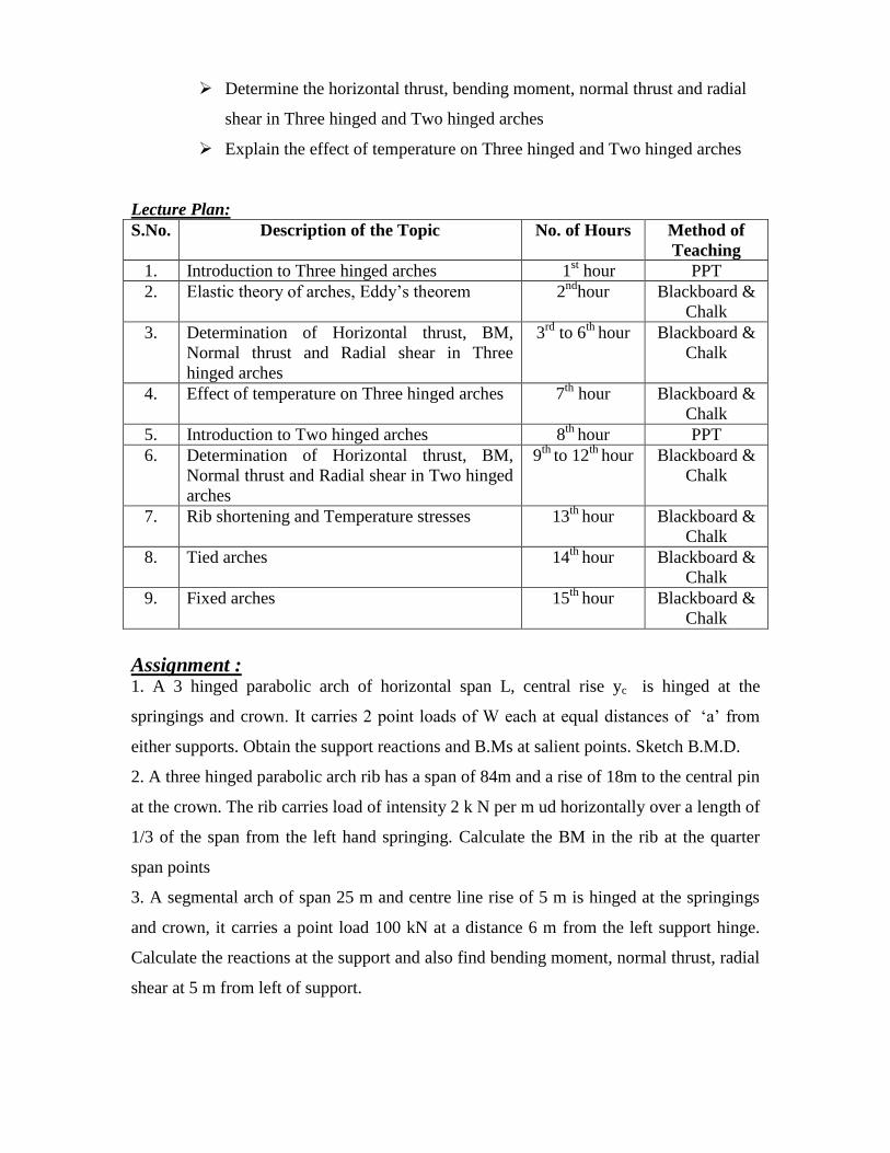
Determine the horizontal thrust, bending moment, normal thrust and radial
shear in Three hinged and Two hinged arches
Explain the effect of temperature on Three hinged and Two hinged arches
Lecture Plan:
S.No. Description of the Topic No. of Hours Method of
Teaching
1. Introduction to Three hinged arches 1st hour PPT
2. Elastic theory of arches, Eddy’s theorem 2nd
hour
Blackboard &
Chalk
3. Determination of Horizontal thrust, BM,
Normal thrust and Radial shear in Three
hinged arches
3rd
to 6th
hour Blackboard &
Chalk
4. Effect of temperature on Three hinged arches 7th
hour Blackboard &
Chalk
5. Introduction to Two hinged arches 8th
hour PPT
6. Determination of Horizontal thrust, BM,
Normal thrust and Radial shear in Two hinged
arches
9th
to 12th
hour Blackboard &
Chalk
7. Rib shortening and Temperature stresses 13th
hour Blackboard &
Chalk
8. Tied arches 14th
hour Blackboard &
Chalk
9. Fixed arches 15th
hour Blackboard &
Chalk
Assignment : 1. A 3 hinged parabolic arch of horizontal span L, central rise yc is hinged at the
springings and crown. It carries 2 point loads of W each at equal distances of ‘a’ from
either supports. Obtain the support reactions and B.Ms at salient points. Sketch B.M.D.
2. A three hinged parabolic arch rib has a span of 84m and a rise of 18m to the central pin
at the crown. The rib carries load of intensity 2 k N per m ud horizontally over a length of
1/3 of the span from the left hand springing. Calculate the BM in the rib at the quarter
span points
3. A segmental arch of span 25 m and centre line rise of 5 m is hinged at the springings
and crown, it carries a point load 100 kN at a distance 6 m from the left support hinge.
Calculate the reactions at the support and also find bending moment, normal thrust, radial
shear at 5 m from left of support.
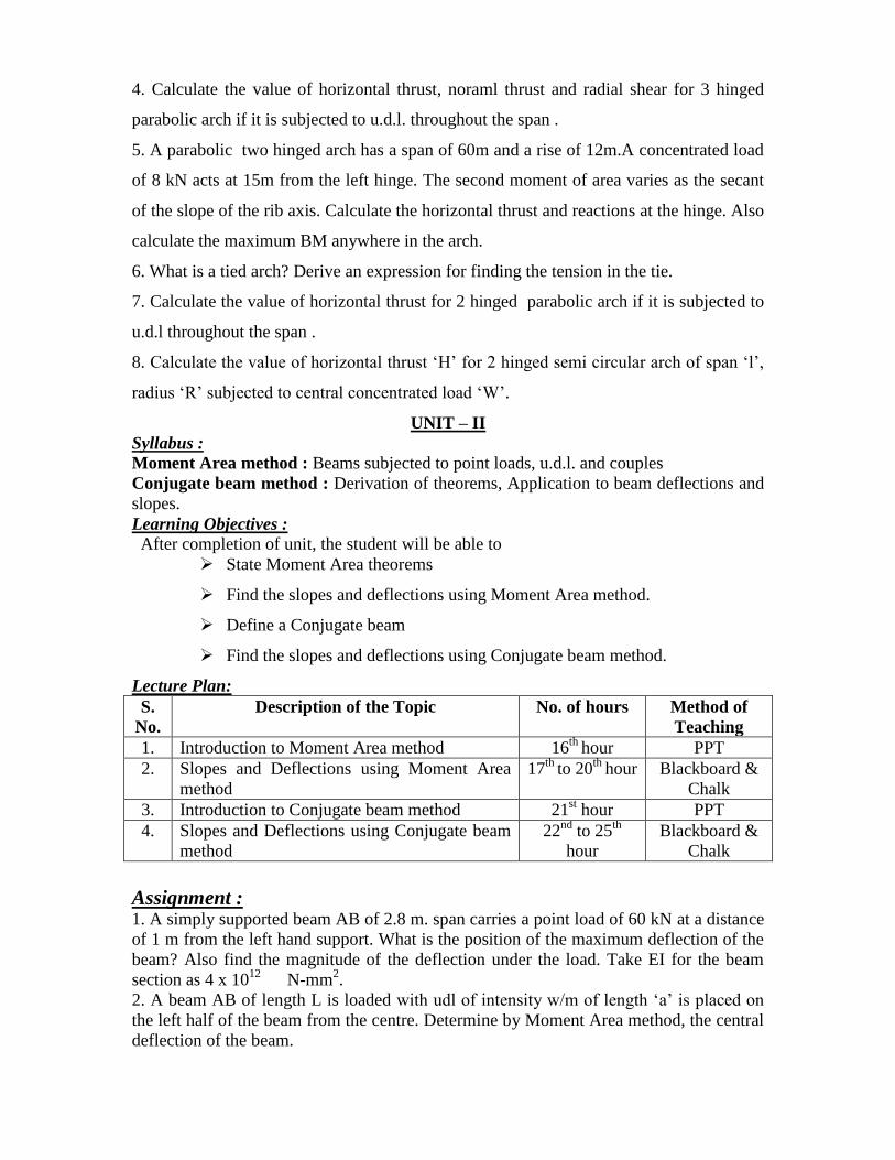
4. Calculate the value of horizontal thrust, noraml thrust and radial shear for 3 hinged
parabolic arch if it is subjected to u.d.l. throughout the span .
5. A parabolic two hinged arch has a span of 60m and a rise of 12m.A concentrated load
of 8 kN acts at 15m from the left hinge. The second moment of area varies as the secant
of the slope of the rib axis. Calculate the horizontal thrust and reactions at the hinge. Also
calculate the maximum BM anywhere in the arch.
6. What is a tied arch? Derive an expression for finding the tension in the tie.
7. Calculate the value of horizontal thrust for 2 hinged parabolic arch if it is subjected to
u.d.l throughout the span .
8. Calculate the value of horizontal thrust ‘H’ for 2 hinged semi circular arch of span ‘l’,
radius ‘R’ subjected to central concentrated load ‘W’.
UNIT – II
Syllabus :
Moment Area method : Beams subjected to point loads, u.d.l. and couples
Conjugate beam method : Derivation of theorems, Application to beam deflections and
slopes.
Learning Objectives :
After completion of unit, the student will be able to
State Moment Area theorems
Find the slopes and deflections using Moment Area method.
Define a Conjugate beam
Find the slopes and deflections using Conjugate beam method.
Lecture Plan:
S.
No.
Description of the Topic No. of hours Method of
Teaching
1. Introduction to Moment Area method 16th
hour PPT
2. Slopes and Deflections using Moment Area
method
17th
to 20th
hour Blackboard &
Chalk
3. Introduction to Conjugate beam method 21st hour PPT
4. Slopes and Deflections using Conjugate beam
method
22nd
to 25th
hour
Blackboard &
Chalk
Assignment : 1. A simply supported beam AB of 2.8 m. span carries a point load of 60 kN at a distance
of 1 m from the left hand support. What is the position of the maximum deflection of the
beam? Also find the magnitude of the deflection under the load. Take EI for the beam
section as 4 x 10¹²
N-mm2.
2. A beam AB of length L is loaded with udl of intensity w/m of length ‘a’ is placed on
the left half of the beam from the centre. Determine by Moment Area method, the central
deflection of the beam.
3. A cantilever beam AB of span L is carrying a point load W at B. The moment of
inertia for the left half is 2I, whereas for the right half is I. Find the slope and deflection
at B in terms of EI,W and L.
4. A beam ABCD is simply supported at its ends A and D over a span of 30 m. It is made
up of 3 portions AB, BC and CD each of 10 m. in length. The moment of inertia of
section over each of these individual portions is uniform and the I values for them are I,
3I and 2I respectively, where I = 20 x109 mm
4. The beam carries a point load of 150 kN
at B and another point load of 300 kN at C. Neglecting the self weight of the beam,
calculate the deflection at B and the slope at C. Take the values of E as 200 GPa.
UNIT – III
Syllabus :
Moment distribution method : Stiffness and carryover factors - Distribution factors -
Analysis of continuous beams with and without sinking of supports
Kani’s method : Analysis of continuous beams - including settlement of supports and
single bay single story portal frames with side sway
Learning Objectives :
After completion of unit, the student will be able to
Define distribution factor, carryover factor
Analyse a continuous beam with and without sinking of supports using
Moment distribution method
Analyse a continuous beam with and without sinking of supports using
Kani’s method
Analyse single bay single story portal frames including side sway by Kani’s
method.
Lecture Plan:
S.
No.
Description of the Topic Period Method of
Teaching
1. Introduction to Moment Distribution method 26th
to 27th
hour
PPT
2. Analysis of continuous beams without sinking
of supports using Moment distribution method
28th
to 29th
hour
Blackboard &
Chalk
3. Analysis of continuous beams with sinking of
supports using Moment distribution method
30th
to 31st
hour
Blackboard &
Chalk
4. Introduction to Kani’s method 32nd
to 33rd
hour
PPT
5. Analysis of continuous beams without sinking
of supports using Kani’s method
34th
to35th
hour Blackboard &
Chalk
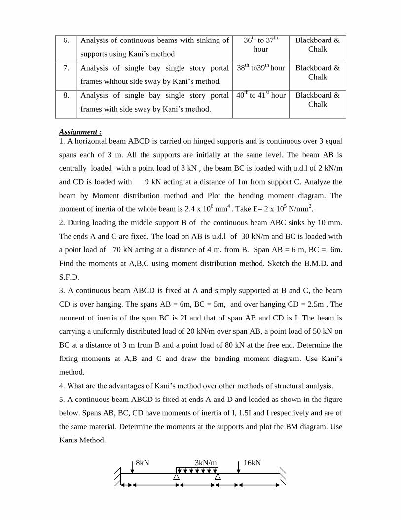
6. Analysis of continuous beams with sinking of
supports using Kani’s method
36th
to 37th
hour
Blackboard &
Chalk
7. Analysis of single bay single story portal
frames without side sway by Kani’s method.
38th
to39th
hour Blackboard &
Chalk
8. Analysis of single bay single story portal
frames with side sway by Kani’s method.
40th
to 41st hour Blackboard &
Chalk
Assignment :
1. A horizontal beam ABCD is carried on hinged supports and is continuous over 3 equal
spans each of 3 m. All the supports are initially at the same level. The beam AB is
centrally loaded with a point load of 8 kN , the beam BC is loaded with u.d.l of 2 kN/m
and CD is loaded with 9 kN acting at a distance of 1m from support C. Analyze the
beam by Moment distribution method and Plot the bending moment diagram. The
moment of inertia of the whole beam is 2.4 x 106 mm
4 . Take E= 2 x 10
5 N/mm
2.
2. During loading the middle support B of the continuous beam ABC sinks by 10 mm.
The ends A and C are fixed. The load on AB is u.d.l of 30 kN/m and BC is loaded with
a point load of 70 kN acting at a distance of 4 m. from B. Span AB = 6 m, BC = 6m.
Find the moments at A,B,C using moment distribution method. Sketch the B.M.D. and
S.F.D.
3. A continuous beam ABCD is fixed at A and simply supported at B and C, the beam
CD is over hanging. The spans AB = 6m, BC = 5m, and over hanging CD = 2.5m . The
moment of inertia of the span BC is 2I and that of span AB and CD is I. The beam is
carrying a uniformly distributed load of 20 kN/m over span AB, a point load of 50 kN on
BC at a distance of 3 m from B and a point load of 80 kN at the free end. Determine the
fixing moments at A,B and C and draw the bending moment diagram. Use Kani’s
method.
4. What are the advantages of Kani’s method over other methods of structural analysis.
5. A continuous beam ABCD is fixed at ends A and D and loaded as shown in the figure
below. Spans AB, BC, CD have moments of inertia of I, 1.5I and I respectively and are of
the same material. Determine the moments at the supports and plot the BM diagram. Use
Kanis Method.
8kN 3kN/m 16kN
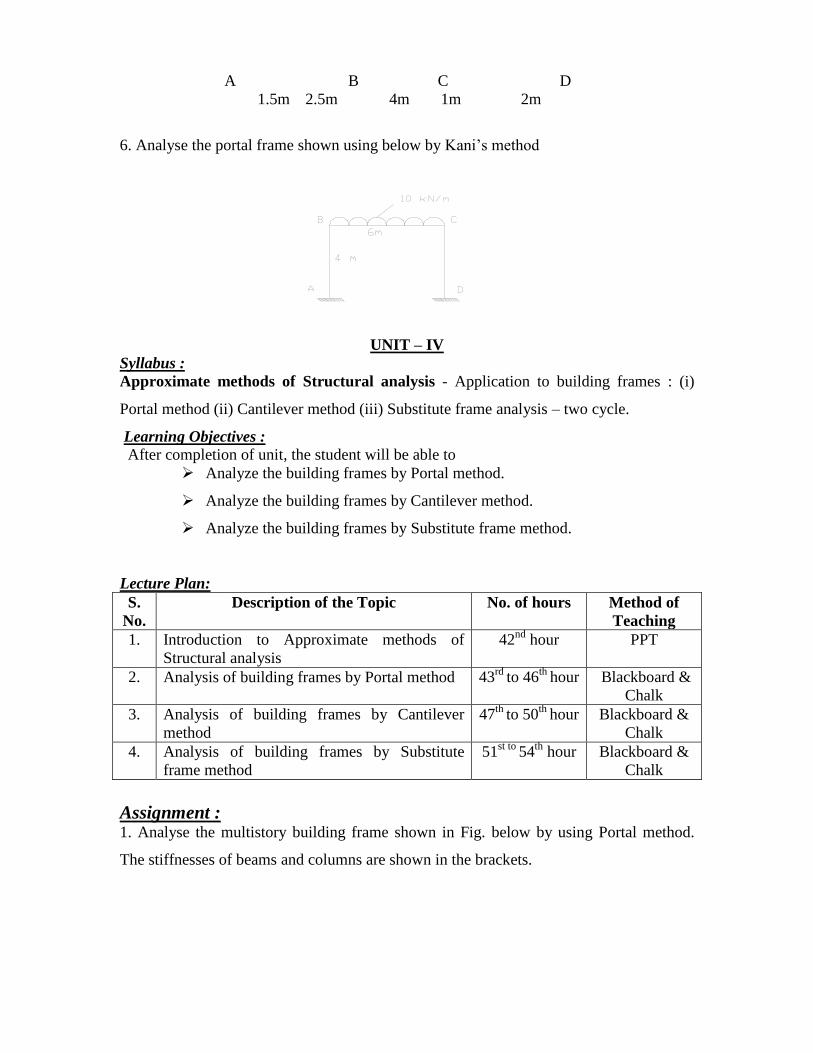
A B C D
1.5m 2.5m 4m 1m 2m
6. Analyse the portal frame shown using below by Kani’s method
UNIT – IV
Syllabus :
Approximate methods of Structural analysis - Application to building frames : (i)
Portal method (ii) Cantilever method (iii) Substitute frame analysis – two cycle.
Learning Objectives :
After completion of unit, the student will be able to
Analyze the building frames by Portal method.
Analyze the building frames by Cantilever method.
Analyze the building frames by Substitute frame method.
Lecture Plan:
S.
No.
Description of the Topic No. of hours Method of
Teaching
1. Introduction to Approximate methods of
Structural analysis
42nd
hour PPT
2. Analysis of building frames by Portal method 43rd
to 46th
hour Blackboard &
Chalk
3. Analysis of building frames by Cantilever
method
47th
to 50th
hour Blackboard &
Chalk
4. Analysis of building frames by Substitute
frame method
51st to
54th
hour Blackboard &
Chalk
Assignment : 1. Analyse the multistory building frame shown in Fig. below by using Portal method.
The stiffnesses of beams and columns are shown in the brackets.
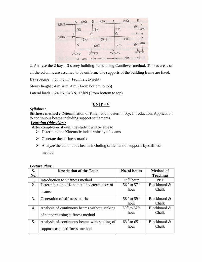
2. Analyse the 2 bay – 3 storey building frame using Cantilever method. The c/s areas of
all the columns are assumed to be uniform. The supports of the building frame are fixed.
Bay spacing : 6 m, 6 m. (From left to right)
Storey height : 4 m, 4 m, 4 m. (From bottom to top)
Lateral loads : 24 kN, 24 kN, 12 kN (From bottom to top)
UNIT – V
Syllabus :
Stiffness method : Determination of Kinematic indeterminacy, Introduction, Application
to continuous beams including support settlements.
Learning Objectives :
After completion of unit, the student will be able to
Determine the Kinematic indeterminacy of beams
Generate the stiffness matrix
Analyze the continuous beams including settlement of supports by stiffness
method
Lecture Plan:
S.
No.
Description of the Topic No. of hours Method of
Teaching
1. Introduction to Stiffness method 55th
hour
PPT
2. Determination of Kinematic indeterminacy of
beams
56th
to 57th
hour
Blackboard &
Chalk
3. Generation of stiffness matrix 58th
to 59th
hour
Blackboard &
Chalk
4. Analysis of continuous beams without sinking
of supports using stiffness method
60th
to 62nd
hour
Blackboard &
Chalk
5. Analysis of continuous beams with sinking of
supports using stiffness method
63rd
to 65th
hour
Blackboard &
Chalk

Assignment : 1. In a continuous beam ABCD, A is fixed, B and C are simply supported and D is over
hanging. AB is loaded with a central concentrated load of 15 kN, BC is loaded with u.d.l
of 10 kN/m and a point load of 20 kN is acting at D. The spans AB = 4m, BC = 6m, CD
= 2m. Analyse this beam by stiffness method Take E= 200 GN/m2 and I= 10 x 10
4 mm
4.
Sketch the BMD.
2). A two span continuous beam ABC is fixed at A and C. The span AB = BC = L. Using
displacement method, obtain the moment at support B if the support C settles by Δ =
L/100.


