Vision and requirements for the satellite radio … Next-Generation Network OFDM Orthogonal...
33
Report ITU-R M.2176 (07/2010) Vision and requirements for the satellite radio interface(s) of IMT-Advanced M Series Mobile, radiodetermination, amateur and related satellites services
Transcript of Vision and requirements for the satellite radio … Next-Generation Network OFDM Orthogonal...
Report ITU-R M.2176(07/2010)
Vision and requirements for the satellite radio interface(s) of IMT-Advanced
M Series
Mobile, radiodetermination, amateurand related satellites services
ii Rep. ITU-R M.2176
Foreword
The role of the Radiocommunication Sector is to ensure the rational, equitable, efficient and economical use of the radio-frequency spectrum by all radiocommunication services, including satellite services, and carry out studies without limit of frequency range on the basis of which Recommendations are adopted.
The regulatory and policy functions of the Radiocommunication Sector are performed by World and Regional Radiocommunication Conferences and Radiocommunication Assemblies supported by Study Groups.
Policy on Intellectual Property Right (IPR)
ITU-R policy on IPR is described in the Common Patent Policy for ITU-T/ITU-R/ISO/IEC referenced in Annex 1 of Resolution ITU-R 1. Forms to be used for the submission of patent statements and licensing declarations by patent holders are available from http://www.itu.int/ITU-R/go/patents/en where the Guidelines for Implementation of the Common Patent Policy for ITU-T/ITU-R/ISO/IEC and the ITU-R patent information database can also be found.
Series of ITU-R Reports
(Also available online at http://www.itu.int/publ/R-REP/en)
Series Title
BO Satellite delivery
BR Recording for production, archival and play-out; film for television
BS Broadcasting service (sound)
BT Broadcasting service (television)
F Fixed service
M Mobile, radiodetermination, amateur and related satellite services
P Radiowave propagation
RA Radio astronomy
RS Remote sensing systems
S Fixed-satellite service
SA Space applications and meteorology
SF Frequency sharing and coordination between fixed-satellite and fixed service systems
SM Spectrum management
Note: This ITU-R Report was approved in English by the Study Group under the procedure detailed in Resolution ITU-R 1.
Electronic Publication Geneva, 2010
ITU 2010
All rights reserved. No part of this publication may be reproduced, by any means whatsoever, without written permission of ITU.
Rep. ITU-R M.2176 1
REPORT ITU-R M.2176
Vision and requirements for the satellite radio interface(s) of IMT-Advanced
(2010)
TABLE OF CONTENTS
Page
1 Introduction .................................................................................................................... 2
2 Scope .............................................................................................................................. 2
3 Structure of the Report ................................................................................................... 3
4 Related ITU documents .................................................................................................. 3
5 List of definitions, acronyms and abbreviations ............................................................. 3
5.1 Definitions .......................................................................................................... 3
5.2 Acronyms and abbreviations .............................................................................. 3
6 Visions on the satellite component of IMT-Advanced ................................................... 5
6.1 Application scenarios .......................................................................................... 5
6.2 Services aspects .................................................................................................. 5
6.3 System aspects .................................................................................................... 7
6.4 Radio interface aspects ....................................................................................... 8
6.5 Possible system architectures for the satellite component of IMT-Advanced ... 9
7 Requirements for the satellite radio interface(s) of IMT-Advanced .............................. 10
7.1 Service requirements .......................................................................................... 10
7.2 Technical requirements ....................................................................................... 12
8 Guidelines for evaluation of the satellite radio interface(s) of IMT-Advanced ............. 15
8.1 Evaluation criteria ............................................................................................... 15
8.2 Evaluation methodology ..................................................................................... 16
9 Reference ........................................................................................................................ 31
2 Rep. ITU-R M.2176
1 Introduction
International Mobile Telecommunications-Advanced (IMT-Advanced) systems are mobile systems that include the new capabilities of IMT that go beyond those of IMT-2000. Such systems provide access to a wide range of telecommunication services, including advanced mobile services supported by mobile and fixed networks, which are increasingly packet-based.
IMT-Advanced systems support low to high mobility applications and a wide range of data rates in accordance with user and service demands in multiple user environments. IMT-Advanced also has capabilities for high-quality multimedia applications within a wide range of services and platforms providing a significant improvement in performance and quality of service.
The key features of IMT-Advanced are:
– a high degree of commonality of functionality worldwide while retaining the flexibility to support a wide range of services and applications in a cost efficient manner;
– compatibility of services within IMT and with fixed networks;
– capability of interworking with other radio access systems;
– high-quality mobile services;
– user equipment suitable for worldwide use;
– user-friendly applications, service and equipment;
– worldwide roaming capability;
– enhanced peak data rates (i.e. wideband) to support advanced services and applications.
These features enable IMT-Advanced to address evolving user needs.
The capabilities of IMT-Advanced systems are being continuously enhanced in line with user trends and technology developments.
The satellite component of IMT-Advanced will be an integral part of future IMT infrastructure with the optimized service delivery.
Regarding the development of terrestrial radio interface(s) of IMT-Advanced, ITU-R WP 5D has already developed the Reports ITU-R M.2133, ITU-R M.2134 and ITU-R M.1235 in order to define service and technical minimum requirement and present evaluation guideline and criteria for the terrestrial radio interface(s) of IMT-Advanced. However, it is indicated that ITU-R WP 5D did not take into consideration characteristics of satellite systems on its development of the related Reports. Therefore, the requirements and evaluation guidelines developed by WP 5D should be considered for the development of satellite radio interface(s) of IMT-Advanced and modified considering specific satellite characteristics, such as longer transmission time between satellite and earth terminal or earth station, if necessary.
2 Scope
The purpose of this Report is to build visions on the satellite component of IMT-Advanced in terms of application scenarios, service, system, radio interface and network aspects and the considered specific features, to address a high-level of the constraints placed on the satellite radio interface(s) of IMT-Advanced particularly with respect to service and technical requirements, and finally to provide evaluation criteria and methodology on the requirements in order to produce Recommendations for development of the satellite radio interface(s) of IMT-Advanced.
Rep. ITU-R M.2176 3
3 Structure of the Report
Section 4 provides a list of the documents that are related to this Report.
Section 5 provides a list of definitions, acronyms and abbreviations.
Section 6 describes visions on the satellite component of IMT-Advanced.
Section 7 defines requirements for the satellite radio interface(s) of IMT-Advanced.
Section 8 provides guidelines for evaluation of candidate satellite radio interface(s) of IMT-Advanced.
Section 9 provides a list of references.
4 Related ITU documents
Resolution ITU-R 57
Recommendation ITU-R M.1645
Recommendation ITU-R M.1822
Report ITU-R M.2133
Report ITU-R M.2134
Report ITU-R M.2135.
5 List of definitions, acronyms and abbreviations
5.1 Definitions
None.
5.2 Acronyms and abbreviations
3GPP Third Generation Partnership Project
ACM Adaptive Coding and Modulation
ARQ Automatic Repeat request
CDMA Code-Division Multiple Access
CGC Complementary Ground Component
DL Downlink
e.i.r.p. Equivalent Isotropically Radiated Power
FDD Frequency-Division Duplexing
FDMA Frequency-Division Multiple Access
FEC Forward Error Correction
FH Frequency Hopping
G/T Antenna Gain to noise Temperature ratio
HARQ Hybrid Automatic Repeat request
IDMA Interleave Division Multiple Access
IEEE Institute of Electrical and Electronics Engineers
IP Internet Protocol
4 Rep. ITU-R M.2176
IPv6 Internet Protocol version 6
IMAP Internet Message Access Protocol
IMT International Mobile Telecommunications
ITS Intelligent Transportation Systems
LMS Land Mobile Satellite
LTE Long-Term Evolution
MAC Media Access Control
MCW Multi-Codeword
MIMO Multi-Input Multi-Output
MS Mobile Station
MUD Multi-User Detection
NGN Next-Generation Network
OFDM Orthogonal Frequency-Division Multiplexing
OFDMA Orthogonal Frequency-Division Multiplexing Access
PAPR Peak to Average Power Ratio
PF Proportional Fairness
PHY Physical
PN Pseudo Noise
QoS Quality of Service
POP Post Office Protocol
RF Radio Frequency
RIT Radio Interface Technology
RRM Radio Resource Management
RNC Radio Network Controller
RX Receiver
SCW Single Codeword
SDMA Space-Division Multiple Access
SRIT Set of Radio Interface Technology
STBC Space-Time Block Coding
STC Space-Time Coding
TDD Time-Division Duplexing
TDMA Time-Division Multiple Access
TX Transmitter
UL Uplink
UT User Terminal
VoIP Voice over Internet Protocol
Rep. ITU-R M.2176 5
6 Visions on the satellite component of IMT-Advanced
IMT-Advanced systems are mobile service systems that include the new capabilities of IMT going beyond those of IMT-2000. Such systems provide access to a wide range of telecommunication services, including advanced mobile services supported by mobile and fixed networks, which are increasingly packet-based. IMT-Advanced systems support low to high-mobility applications and a wide range of data in accordance with user and service demands in multiple user environments. IMT-Advanced also has capabilities for high quality multimedia applications in a wide range of services and platforms anywhere, providing a significant improvement in performance and quality of service.
In order to provide the seamless service in a global coverage, the satellite component of IMT-Advanced systems would be considered because the terrestrial component only would not be possible to be deployed all over the world.
The aim of this section is to define visions on satellite component of IMT-Advanced for an efficient IMT service delivery with respect to application scenarios, services, system, radio and network interface aspects, and to provide possible candidate system architectures.
6.1 Application scenarios
The application scenarios include:
– two-way communications using multibeam with frequency reuse scheme;
– interactive digital multimedia broadcasting using multibeam.
The two-way communications can be regarded as a coverage extension on service continuity of terrestrial part with vertical handover. One of the major advantages using satellite is its capability to provide a global coverage. It can offer services in certain regions outside terrestrial coverage. The areas not adequately covered by terrestrial part include physically isolated regions, gap of terrestrial network and areas where terrestrial collapses due to disaster. In the scenario of “two-way communications using multibeam with frequency reuse scheme”, handover technique between the satellite and terrestrial component of IMT-Advanced system would be the most important to consider. For the cost-effective vertical handover, future satellite radio interfaces of IMT-Advanced should be compatible and may have a high degree of commonality with an envisaged terrestrial interface. It would offer the possibility to reuse terrestrial part technology to minimize user terminal chipset and network equipment for low cost and fast development.
In addition, the satellite radio interface considered for “two-way communications” scenario with some adaptation with satellite environment can provide interactive multimedia broadcasting services, as the envisaged terrestrial radio interfaces of IMT-Advanced is being developed in order to handle efficiently multimedia broadcasting and multicasting services as well as a bidirectional communication services in a cellular system. In the “interactive multimedia broadcasting” scenario, an integrated satellite and CGC infrastructure would be required. Indeed, the satellite component of IMT-Advanced has an advantage over terrestrial component for delivery of same contents to spread over a wide geographical area.
6.2 Services aspects
The following high-level requirements are described in Recommendation ITU-R M.1822:
– Seamless connectivity
– Mobility management
– Interoperability
– Constant connections
6 Rep. ITU-R M.2176
– Applicability scalability
– Security
– Prioritization
– Location
– Broadcast/multicast
– Presence
– Usability including voice reconfiguration and user-friendly human-to-machine interface
– Support of a wide range of services.
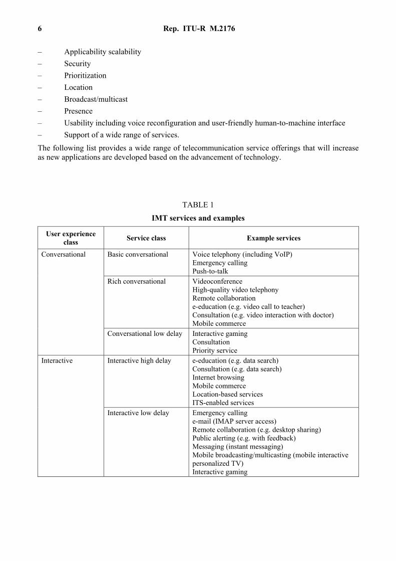
The following list provides a wide range of telecommunication service offerings that will increase as new applications are developed based on the advancement of technology.
TABLE 1
IMT services and examples
User experience class
Service class Example services
Conversational Basic conversational Voice telephony (including VoIP) Emergency calling Push-to-talk
Rich conversational Videoconference High-quality video telephony Remote collaboration e-education (e.g. video call to teacher) Consultation (e.g. video interaction with doctor) Mobile commerce
Conversational low delay Interactive gaming Consultation Priority service
Interactive Interactive high delay e-education (e.g. data search) Consultation (e.g. data search) Internet browsing Mobile commerce Location-based services ITS-enabled services
Interactive low delay Emergency calling e-mail (IMAP server access) Remote collaboration (e.g. desktop sharing) Public alerting (e.g. with feedback) Messaging (instant messaging) Mobile broadcasting/multicasting (mobile interactive personalized TV) Interactive gaming
Rep. ITU-R M.2176 7
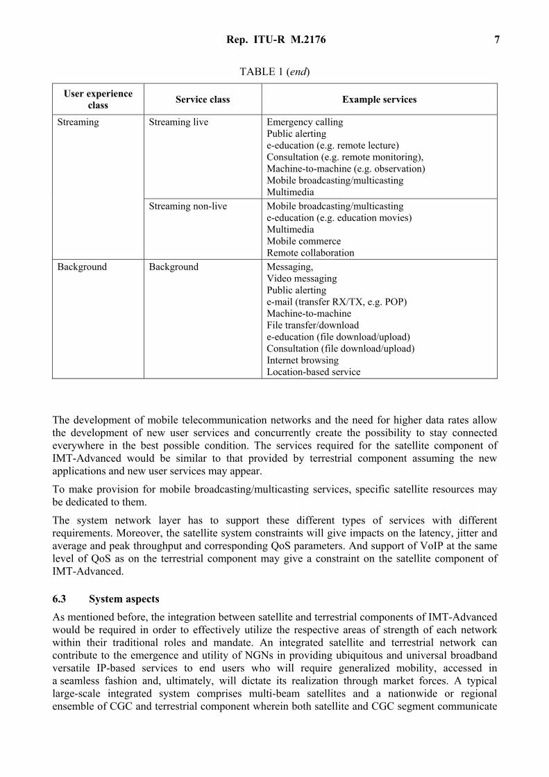
TABLE 1 (end)
User experience class
Service class Example services
Streaming Streaming live Emergency calling Public alerting e-education (e.g. remote lecture) Consultation (e.g. remote monitoring), Machine-to-machine (e.g. observation) Mobile broadcasting/multicasting Multimedia
Streaming non-live Mobile broadcasting/multicasting e-education (e.g. education movies) Multimedia Mobile commerce Remote collaboration
Background Background Messaging, Video messaging Public alerting e-mail (transfer RX/TX, e.g. POP) Machine-to-machine File transfer/download e-education (file download/upload) Consultation (file download/upload) Internet browsing Location-based service
The development of mobile telecommunication networks and the need for higher data rates allow the development of new user services and concurrently create the possibility to stay connected everywhere in the best possible condition. The services required for the satellite component of IMT-Advanced would be similar to that provided by terrestrial component assuming the new applications and new user services may appear.
To make provision for mobile broadcasting/multicasting services, specific satellite resources may be dedicated to them.
The system network layer has to support these different types of services with different requirements. Moreover, the satellite system constraints will give impacts on the latency, jitter and average and peak throughput and corresponding QoS parameters. And support of VoIP at the same level of QoS as on the terrestrial component may give a constraint on the satellite component of IMT-Advanced.
6.3 System aspects
As mentioned before, the integration between satellite and terrestrial components of IMT-Advanced would be required in order to effectively utilize the respective areas of strength of each network within their traditional roles and mandate. An integrated satellite and terrestrial network can contribute to the emergence and utility of NGNs in providing ubiquitous and universal broadband versatile IP-based services to end users who will require generalized mobility, accessed in a seamless fashion and, ultimately, will dictate its realization through market forces. A typical large-scale integrated system comprises multi-beam satellites and a nationwide or regional ensemble of CGC and terrestrial component wherein both satellite and CGC segment communicate
8 Rep. ITU-R M.2176
with user equipment using a common set of MSS frequencies to handle broadcasting scenarios, while terrestrial components using a separate set of frequencies to provide ubiquitous coverage of broadband two-way communications to end users with generalized mobility requirements.
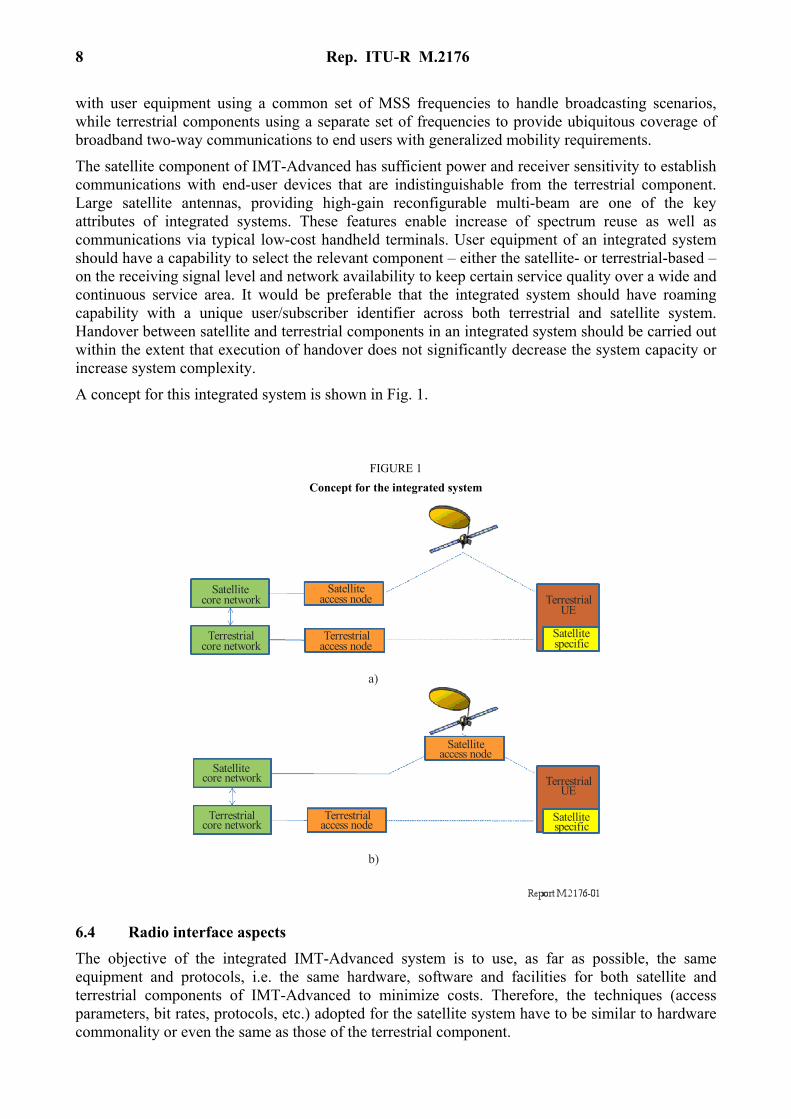
The satellite component of IMT-Advanced has sufficient power and receiver sensitivity to establish communications with end-user devices that are indistinguishable from the terrestrial component. Large satellite antennas, providing high-gain reconfigurable multi-beam are one of the key attributes of integrated systems. These features enable increase of spectrum reuse as well as communications via typical low-cost handheld terminals. User equipment of an integrated system should have a capability to select the relevant component – either the satellite- or terrestrial-based – on the receiving signal level and network availability to keep certain service quality over a wide and continuous service area. It would be preferable that the integrated system should have roaming capability with a unique user/subscriber identifier across both terrestrial and satellite system. Handover between satellite and terrestrial components in an integrated system should be carried out within the extent that execution of handover does not significantly decrease the system capacity or increase system complexity.
A concept for this integrated system is shown in Fig. 1.
FIGURE 1
Concept for the integrated system
Terrestrialaccess node
Terrestrialcore network
Satellitespecific
TerrestrialUE
Satellitecore network
Satelliteaccess node
Terrestrialaccess node
Terrestrialcore network
Satellitespecific
TerrestrialUE
Satellitecore network
Satelliteaccess node
a)
b)
6.4 Radio interface aspects
The objective of the integrated IMT-Advanced system is to use, as far as possible, the same equipment and protocols, i.e. the same hardware, software and facilities for both satellite and terrestrial components of IMT-Advanced to minimize costs. Therefore, the techniques (access parameters, bit rates, protocols, etc.) adopted for the satellite system have to be similar to hardware commonality or even the same as those of the terrestrial component.
Rep. ITU-R M.2176 9
In particular, the satellite radio interface of IMT-Advanced should be compatible, and may have a high degree of commonality with, a terrestrial radio interface. It may bring the possibility to reuse terrestrial part technology to minimize user terminal chipset and network equipment for low cost and fast development. It can also have several different features from terrestrial radio interface to reflect the satellite-specific characteristics, such as long round-trip delay and power limitation.
As the candidate terrestrial radio interfaces of IMT-Advanced, 3GPP LTE-Advanced and IEEE 802.16m radio interfaces are being considered. Key technology of both radio interfaces is to use OFDM waveform, which is intrinsically able to handle the most common radio frequency distortion without the need for complex equalization techniques and scales easily to fit different bandwidth requirements, and MIMO, which increases peak throughput by transmitting and receiving multiple streams of information within the same spectrum. In general, the combined use of OFDM and MIMO will improve the spectral efficiency and capacity of the wireless network, and will prove to be a very valuable asset in maximizing usage of scarce spectrum typically controlled by regulatory bodies. With the requirement on commonality or similarity between satellite and terrestrial components in the integrated system, these advantages may urge to select OFDM waveform and MIMO technology for the satellite radio interface of IMT-Advanced.
In addition, some advanced technologies considered in the terrestrial components can be brought for the satellite component as follows:
– multi-hop relay which is introduced to enable traffic/signalling forwarding between a satellite and user equipments by breaking a long-distance low-quality link into two or more high-quality segments and then is able to improve user throughput and provide a better user experience;
– spectrum aggregation where two or more component carriers are aggregated in order to support wider transmission via wider bandwidth;
– support of scalable bandwidth wherein a satellite can support a plurality of maximum bandwidths and flexibly allocate bandwidths user equipments from the maximum bandwidths;
– MIMO techniques in forward and return links from multi-satellites, dual polarization and so on;
– network MIMO in which antennas from neighbouring beams can be combined to transmit multiple stream to beam-edge users in order to inter-beam interference;
– inter-beam interference management including inter-beam interference cancellation, interference avoidance and interference coordination techniques in order to increase beam-edge throughput;
– self-organizing/optimizing network which can automatically extend, change, configure and optimize the network coverage, capacity, beam size, topology, and frequency allocation and bandwidth, based on changes in interference, signal strength, location, traffic pattern, and other environment criteria.
6.5 Possible system architectures for the satellite component of IMT-Advanced
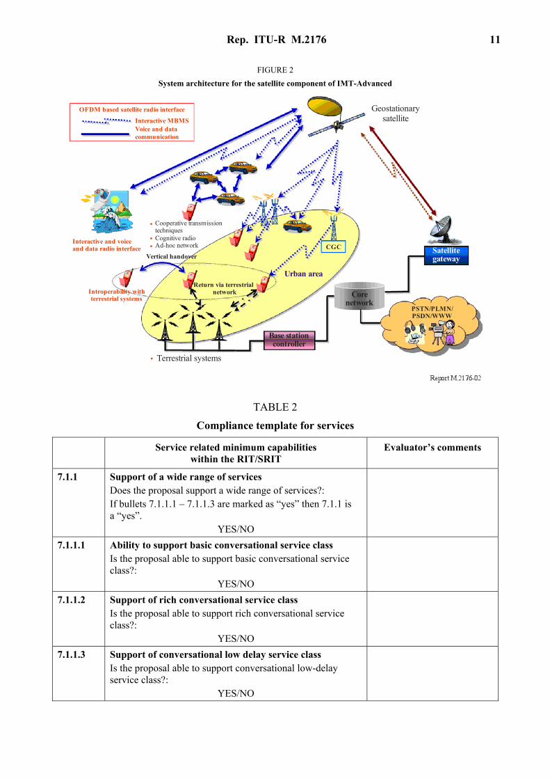
Figure 2 describes overall system architecture for the considered system concept. The following factors can be considered:
– Satellite: It will provide services and applications similar to those of terrestrial systems outside terrestrial and CGC coverage under the inherent constraints imposed by power limitation and long round-trip delay.
10 Rep. ITU-R M.2176
– CGCs: In order to provide mobile broadcasting/multicasting services, they can be deployed in areas where satellite reception is difficult, especially in urban areas. They may be co-located with terrestrial cell sites or standalone. Several kinds can be considered, such as simple amplifying and forwarding CGC like simple repeaters, a demodulation and forwarding CGC for high modulation and a decoding and forwarding CGC for better traffic quality. It would require careful consideration to use the same frequency band in satellite systems and CGC, since the CGC would possibly cause harmful interference to their own terminal or radiocommunication systems which are operated in the adjacent band and which do not expect that the adjacent band originally allocated to satellite system is used also for the CGC with higher power density rather than satellite’s one.
– Terrestrial component: The satellite component can allow to provide voice and data communication services in regions outside terrestrial coverage. The areas not adequately covered by the terrestrial component include physically isolated regions, gaps in the terrestrial component and areas where terrestrial component permanently, or temporarily, collapses due to disaster. In order to provide the terrestrial fill-in service, vertical handover of satellite component with terrestrial part may be considered as one of the most important techniques.
– Advanced technologies: the following “IMT-Advanced enabling technologies” can be considered in enhancing the cost-effectiveness and competitiveness of the satellite component.
i) Horizontal integration of services and networks on personal mobile devices (SDR).
ii) Optimized communication techniques (MIMO, MUD, turbo detection, HARQ, ACM, pre-equalization, IPv6).
iii) Introduction of new concepts and techniques for increased coverage, data speeds and spectral efficiencies, such as ad-hoc networking, cooperative MIMO and relaying, cognitive radio techniques for dynamic spectral sharing.
7 Requirements for the satellite radio interface(s) of IMT-Advanced
7.1 Service requirements
Recommendation ITU-R M.1822 – Framework for services supported by IMT, addresses the high-level requirements for services and applications to be supported by IMT. It includes service parameters and service classifications of IMT, and service examples that may be supported by IMT.
While a specific set of services is not required, the service classifications in Recommendation ITU-R M.1822 should be used to ensure that a wide range of telecommunication services to mobile users can be provided by IMT.
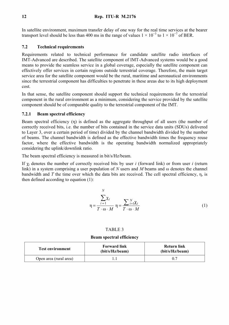
The service capability requirements are in the following compliance template for service in Table 2. Services to be realized in the proposed system are included in Table 2. It is expected that detailed explanation of each service feature or characteristics would be defined by the proponent.
Rep. ITU-R M.2176 11
FIGURE 2
System architecture for the satellite component of IMT-Advanced
Terrestrial systems.Base stationcontroller
Corenetwork
PSTN/PLMN/PSDN/WWW
Satellitegateway
Urban areaReturn via terrestrial
networkIntroperability withterrestrial systems
CGC
Vertical handover
Interactive and voiceand data radio interface
Cooperative transmissiontechniquesCognitive radioAd-hoc network
.
..
Geostationarysatellite
OFDM based satellite radio interface
Interactive MBMSVoice and datacommunication
TABLE 2
Compliance template for services
Service related minimum capabilities within the RIT/SRIT
Evaluator’s comments
7.1.1 Support of a wide range of services Does the proposal support a wide range of services?: If bullets 7.1.1.1 – 7.1.1.3 are marked as “yes” then 7.1.1 is a “yes”.
YES/NO
7.1.1.1 Ability to support basic conversational service class Is the proposal able to support basic conversational service class?:
YES/NO
7.1.1.2 Support of rich conversational service class Is the proposal able to support rich conversational service class?:
YES/NO
7.1.1.3 Support of conversational low delay service class Is the proposal able to support conversational low-delay service class?:
YES/NO
12 Rep. ITU-R M.2176
In satellite environment, maximum transfer delay of one way for the real time services at the bearer transport level should be less than 400 ms in the range of values 1 × 10⁻³ to 1 × 10⁻⁷ of BER.
7.2 Technical requirements
Requirements related to technical performance for candidate satellite radio interfaces of IMT-Advanced are described. The satellite component of IMT-Advanced systems would be a good means to provide the seamless service in a global coverage, especially the satellite component can effectively offer services in certain regions outside terrestrial coverage. Therefore, the main target service area for the satellite component would be the rural, maritime and aeronautical environments since the terrestrial component has difficulties to penetrate in these areas due to its high deployment cost.
In that sense, the satellite component should support the technical requirements for the terrestrial component in the rural environment as a minimum, considering the service provided by the satellite component should be of comparable quality to the terrestrial component of the IMT.
7.2.1 Beam spectral efficiency
Beam spectral efficiency (η) is defined as the aggregate throughput of all users (the number of correctly received bits, i.e. the number of bits contained in the service data units (SDUs) delivered to Layer 3, over a certain period of time) divided by the channel bandwidth divided by the number of beams. The channel bandwidth is defined as the effective bandwidth times the frequency reuse factor, where the effective bandwidth is the operating bandwidth normalized appropriately considering the uplink/downlink ratio.
The beam spectral efficiency is measured in bit/s/Hz/beam.
If χi denotes the number of correctly received bits by user i (forward link) or from user i (return link) in a system comprising a user population of N users and M beams and ω denotes the channel bandwidth and T the time over which the data bits are received. The cell spectral efficiency, η, is then defined according to equation (1):
MT
N
ii
⋅⋅=
=
ω
χ
η 1
MTi
Ni
⋅⋅χ
= =
ωη 1 (1)
TABLE 3
Beam spectral efficiency
Test environment Forward link
(bit/s/Hz/beam) Return link
(bit/s/Hz/beam)
Open area (rural area) 1.1 0.7
Rep. ITU-R M.2176 13
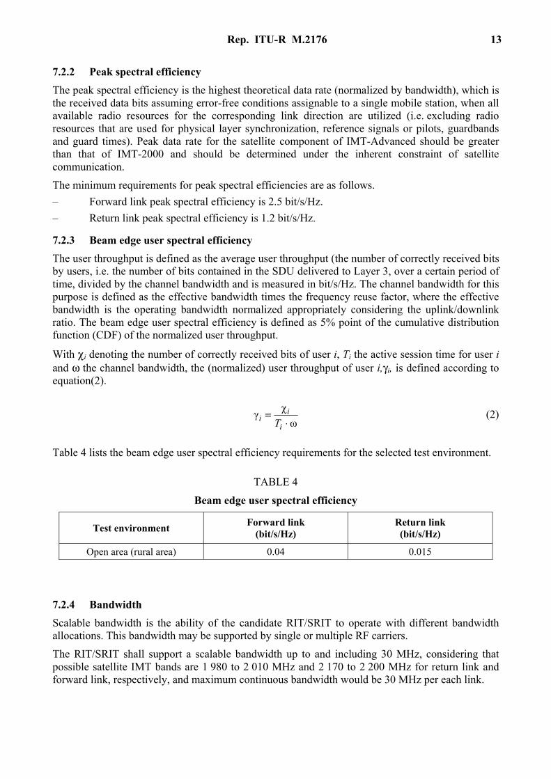
7.2.2 Peak spectral efficiency
The peak spectral efficiency is the highest theoretical data rate (normalized by bandwidth), which is the received data bits assuming error-free conditions assignable to a single mobile station, when all available radio resources for the corresponding link direction are utilized (i.e. excluding radio resources that are used for physical layer synchronization, reference signals or pilots, guardbands and guard times). Peak data rate for the satellite component of IMT-Advanced should be greater than that of IMT-2000 and should be determined under the inherent constraint of satellite communication.
The minimum requirements for peak spectral efficiencies are as follows.
– Forward link peak spectral efficiency is 2.5 bit/s/Hz.
– Return link peak spectral efficiency is 1.2 bit/s/Hz.
7.2.3 Beam edge user spectral efficiency
The user throughput is defined as the average user throughput (the number of correctly received bits by users, i.e. the number of bits contained in the SDU delivered to Layer 3, over a certain period of time, divided by the channel bandwidth and is measured in bit/s/Hz. The channel bandwidth for this purpose is defined as the effective bandwidth times the frequency reuse factor, where the effective bandwidth is the operating bandwidth normalized appropriately considering the uplink/downlink ratio. The beam edge user spectral efficiency is defined as 5% point of the cumulative distribution function (CDF) of the normalized user throughput.
With χi denoting the number of correctly received bits of user i, Ti the active session time for user i and ω the channel bandwidth, the (normalized) user throughput of user i,γi, is defined according to equation(2).
ω
χγ
⋅=
i
ii T
(2)
Table 4 lists the beam edge user spectral efficiency requirements for the selected test environment.
TABLE 4
Beam edge user spectral efficiency
Test environment Forward link
(bit/s/Hz) Return link (bit/s/Hz)
Open area (rural area) 0.04 0.015
7.2.4 Bandwidth
Scalable bandwidth is the ability of the candidate RIT/SRIT to operate with different bandwidth allocations. This bandwidth may be supported by single or multiple RF carriers.
The RIT/SRIT shall support a scalable bandwidth up to and including 30 MHz, considering that possible satellite IMT bands are 1 980 to 2 010 MHz and 2 170 to 2 200 MHz for return link and forward link, respectively, and maximum continuous bandwidth would be 30 MHz per each link.
14 Rep. ITU-R M.2176
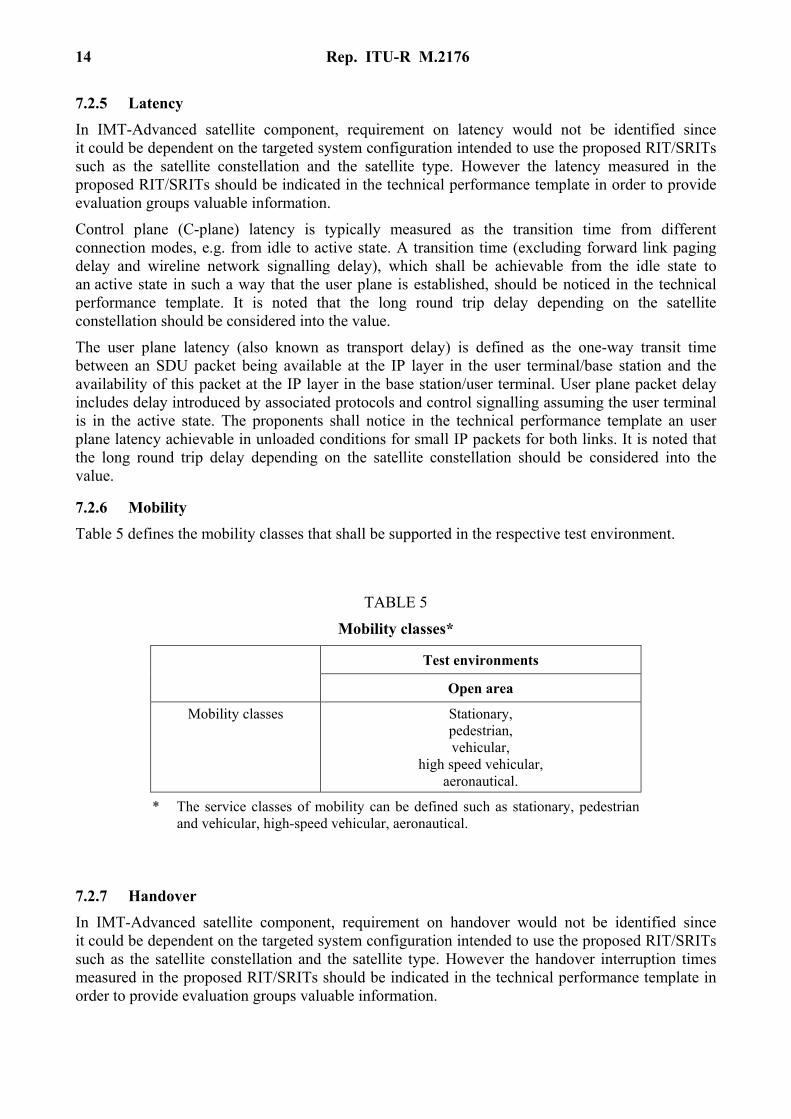
7.2.5 Latency
In IMT-Advanced satellite component, requirement on latency would not be identified since it could be dependent on the targeted system configuration intended to use the proposed RIT/SRITs such as the satellite constellation and the satellite type. However the latency measured in the proposed RIT/SRITs should be indicated in the technical performance template in order to provide evaluation groups valuable information.
Control plane (C-plane) latency is typically measured as the transition time from different connection modes, e.g. from idle to active state. A transition time (excluding forward link paging delay and wireline network signalling delay), which shall be achievable from the idle state to an active state in such a way that the user plane is established, should be noticed in the technical performance template. It is noted that the long round trip delay depending on the satellite constellation should be considered into the value.
The user plane latency (also known as transport delay) is defined as the one-way transit time between an SDU packet being available at the IP layer in the user terminal/base station and the availability of this packet at the IP layer in the base station/user terminal. User plane packet delay includes delay introduced by associated protocols and control signalling assuming the user terminal is in the active state. The proponents shall notice in the technical performance template an user plane latency achievable in unloaded conditions for small IP packets for both links. It is noted that the long round trip delay depending on the satellite constellation should be considered into the value.
7.2.6 Mobility
Table 5 defines the mobility classes that shall be supported in the respective test environment.
TABLE 5
Mobility classes*
Test environments
Open area
Mobility classes Stationary, pedestrian, vehicular,
high speed vehicular, aeronautical.
* The service classes of mobility can be defined such as stationary, pedestrian and vehicular, high-speed vehicular, aeronautical.
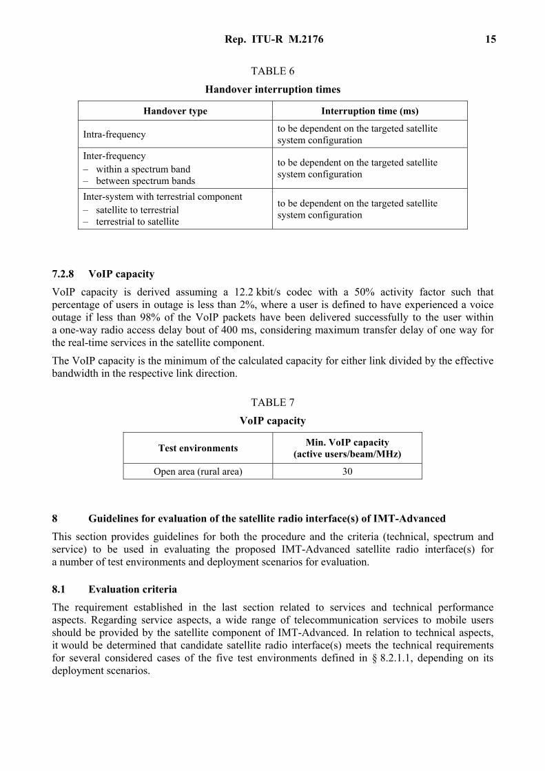
7.2.7 Handover
In IMT-Advanced satellite component, requirement on handover would not be identified since it could be dependent on the targeted system configuration intended to use the proposed RIT/SRITs such as the satellite constellation and the satellite type. However the handover interruption times measured in the proposed RIT/SRITs should be indicated in the technical performance template in order to provide evaluation groups valuable information.
Rep. ITU-R M.2176 15
TABLE 6
Handover interruption times
Handover type Interruption time (ms)
Intra-frequency to be dependent on the targeted satellite system configuration
Inter-frequency – within a spectrum band – between spectrum bands
to be dependent on the targeted satellite system configuration
Inter-system with terrestrial component – satellite to terrestrial – terrestrial to satellite
to be dependent on the targeted satellite system configuration
7.2.8 VoIP capacity
VoIP capacity is derived assuming a 12.2 kbit/s codec with a 50% activity factor such that percentage of users in outage is less than 2%, where a user is defined to have experienced a voice outage if less than 98% of the VoIP packets have been delivered successfully to the user within a one-way radio access delay bout of 400 ms, considering maximum transfer delay of one way for the real-time services in the satellite component.
The VoIP capacity is the minimum of the calculated capacity for either link divided by the effective bandwidth in the respective link direction.
TABLE 7
VoIP capacity
Test environments Min. VoIP capacity
(active users/beam/MHz)
Open area (rural area) 30
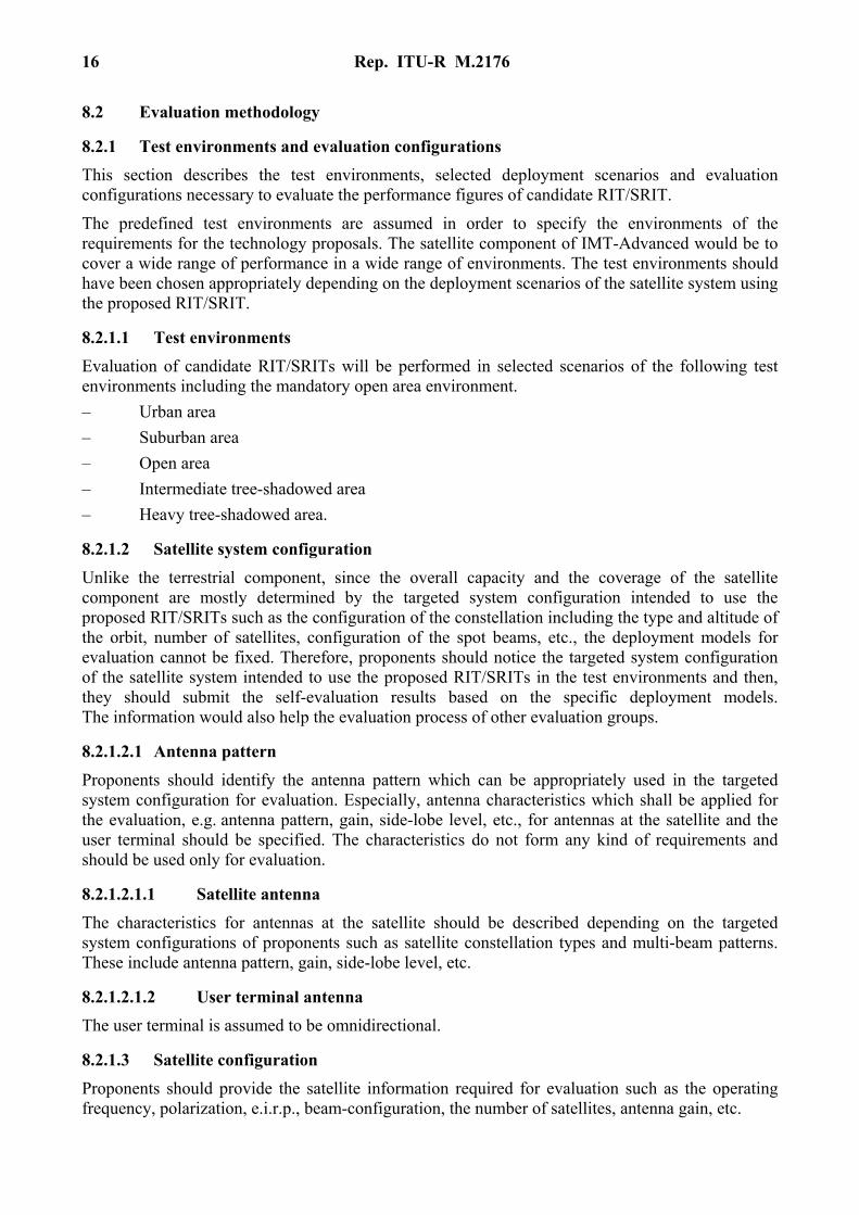
8 Guidelines for evaluation of the satellite radio interface(s) of IMT-Advanced
This section provides guidelines for both the procedure and the criteria (technical, spectrum and service) to be used in evaluating the proposed IMT-Advanced satellite radio interface(s) for a number of test environments and deployment scenarios for evaluation.
8.1 Evaluation criteria
The requirement established in the last section related to services and technical performance aspects. Regarding service aspects, a wide range of telecommunication services to mobile users should be provided by the satellite component of IMT-Advanced. In relation to technical aspects, it would be determined that candidate satellite radio interface(s) meets the technical requirements for several considered cases of the five test environments defined in § 8.2.1.1, depending on its deployment scenarios.
16 Rep. ITU-R M.2176
8.2 Evaluation methodology
8.2.1 Test environments and evaluation configurations
This section describes the test environments, selected deployment scenarios and evaluation configurations necessary to evaluate the performance figures of candidate RIT/SRIT.
The predefined test environments are assumed in order to specify the environments of the requirements for the technology proposals. The satellite component of IMT-Advanced would be to cover a wide range of performance in a wide range of environments. The test environments should have been chosen appropriately depending on the deployment scenarios of the satellite system using the proposed RIT/SRIT.
8.2.1.1 Test environments
Evaluation of candidate RIT/SRITs will be performed in selected scenarios of the following test environments including the mandatory open area environment.
– Urban area
– Suburban area
– Open area
– Intermediate tree-shadowed area
– Heavy tree-shadowed area.
8.2.1.2 Satellite system configuration
Unlike the terrestrial component, since the overall capacity and the coverage of the satellite component are mostly determined by the targeted system configuration intended to use the proposed RIT/SRITs such as the configuration of the constellation including the type and altitude of the orbit, number of satellites, configuration of the spot beams, etc., the deployment models for evaluation cannot be fixed. Therefore, proponents should notice the targeted system configuration of the satellite system intended to use the proposed RIT/SRITs in the test environments and then, they should submit the self-evaluation results based on the specific deployment models. The information would also help the evaluation process of other evaluation groups.
8.2.1.2.1 Antenna pattern
Proponents should identify the antenna pattern which can be appropriately used in the targeted system configuration for evaluation. Especially, antenna characteristics which shall be applied for the evaluation, e.g. antenna pattern, gain, side-lobe level, etc., for antennas at the satellite and the user terminal should be specified. The characteristics do not form any kind of requirements and should be used only for evaluation.
8.2.1.2.1.1 Satellite antenna
The characteristics for antennas at the satellite should be described depending on the targeted system configurations of proponents such as satellite constellation types and multi-beam patterns. These include antenna pattern, gain, side-lobe level, etc.
8.2.1.2.1.2 User terminal antenna
The user terminal is assumed to be omnidirectional.
8.2.1.3 Satellite configuration
Proponents should provide the satellite information required for evaluation such as the operating frequency, polarization, e.i.r.p., beam-configuration, the number of satellites, antenna gain, etc.
Rep. ITU-R M.2176 17
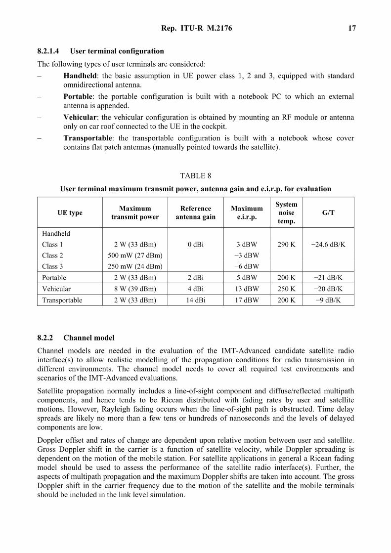
8.2.1.4 User terminal configuration
The following types of user terminals are considered:
– Handheld: the basic assumption in UE power class 1, 2 and 3, equipped with standard omnidirectional antenna.
– Portable: the portable configuration is built with a notebook PC to which an external antenna is appended.
– Vehicular: the vehicular configuration is obtained by mounting an RF module or antenna only on car roof connected to the UE in the cockpit.
– Transportable: the transportable configuration is built with a notebook whose cover contains flat patch antennas (manually pointed towards the satellite).
TABLE 8
User terminal maximum transmit power, antenna gain and e.i.r.p. for evaluation
UE type Maximum
transmit power Reference
antenna gain Maximum
e.i.r.p.
System noise temp.
G/T
Handheld
Class 1 2 W (33 dBm) 0 dBi 3 dBW 290 K −24.6 dB/K
Class 2 500 mW (27 dBm) −3 dBW
Class 3 250 mW (24 dBm) −6 dBW
Portable 2 W (33 dBm) 2 dBi 5 dBW 200 K −21 dB/K
Vehicular 8 W (39 dBm) 4 dBi 13 dBW 250 K −20 dB/K
Transportable 2 W (33 dBm) 14 dBi 17 dBW 200 K −9 dB/K
8.2.2 Channel model
Channel models are needed in the evaluation of the IMT-Advanced candidate satellite radio interface(s) to allow realistic modelling of the propagation conditions for radio transmission in different environments. The channel model needs to cover all required test environments and scenarios of the IMT-Advanced evaluations.
Satellite propagation normally includes a line-of-sight component and diffuse/reflected multipath components, and hence tends to be Ricean distributed with fading rates by user and satellite motions. However, Rayleigh fading occurs when the line-of-sight path is obstructed. Time delay spreads are likely no more than a few tens or hundreds of nanoseconds and the levels of delayed components are low.
Doppler offset and rates of change are dependent upon relative motion between user and satellite. Gross Doppler shift in the carrier is a function of satellite velocity, while Doppler spreading is dependent on the motion of the mobile station. For satellite applications in general a Ricean fading model should be used to assess the performance of the satellite radio interface(s). Further, the aspects of multipath propagation and the maximum Doppler shifts are taken into account. The gross Doppler shift in the carrier frequency due to the motion of the satellite and the mobile terminals should be included in the link level simulation.
18 Rep. ITU-R M.2176
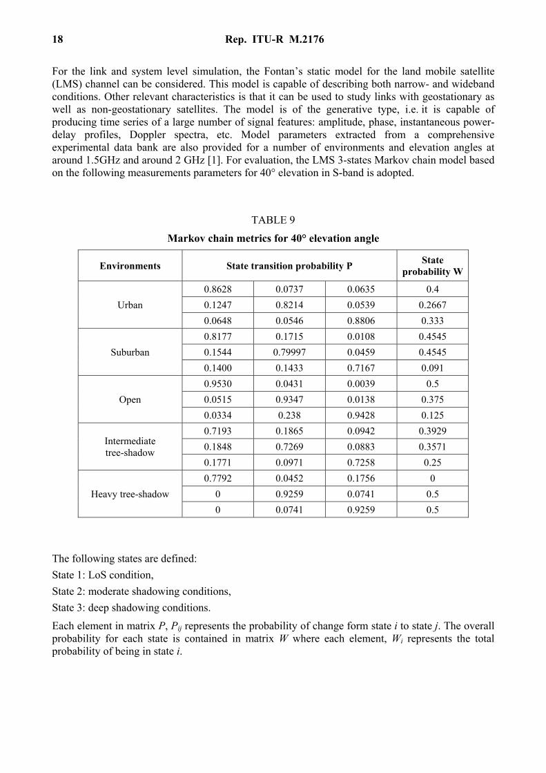
For the link and system level simulation, the Fontan’s static model for the land mobile satellite (LMS) channel can be considered. This model is capable of describing both narrow- and wideband conditions. Other relevant characteristics is that it can be used to study links with geostationary as well as non-geostationary satellites. The model is of the generative type, i.e. it is capable of producing time series of a large number of signal features: amplitude, phase, instantaneous power-delay profiles, Doppler spectra, etc. Model parameters extracted from a comprehensive experimental data bank are also provided for a number of environments and elevation angles at around 1.5GHz and around 2 GHz [1]. For evaluation, the LMS 3-states Markov chain model based on the following measurements parameters for 40° elevation in S-band is adopted.
TABLE 9
Markov chain metrics for 40° elevation angle
Environments State transition probability P State
probability W
Urban
0.8628 0.0737 0.0635 0.4
0.1247 0.8214 0.0539 0.2667
0.0648 0.0546 0.8806 0.333
Suburban
0.8177 0.1715 0.0108 0.4545
0.1544 0.79997 0.0459 0.4545
0.1400 0.1433 0.7167 0.091
Open
0.9530 0.0431 0.0039 0.5
0.0515 0.9347 0.0138 0.375
0.0334 0.238 0.9428 0.125
Intermediate tree-shadow
0.7193 0.1865 0.0942 0.3929
0.1848 0.7269 0.0883 0.3571
0.1771 0.0971 0.7258 0.25
Heavy tree-shadow
0.7792 0.0452 0.1756 0
0 0.9259 0.0741 0.5
0 0.0741 0.9259 0.5
The following states are defined:
State 1: LoS condition,
State 2: moderate shadowing conditions,
State 3: deep shadowing conditions.
Each element in matrix P, Pij represents the probability of change form state i to state j. The overall probability for each state is contained in matrix W where each element, Wi represents the total probability of being in state i.
Rep. ITU-R M.2176 19
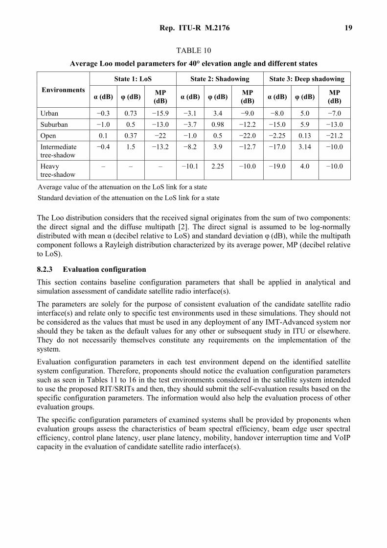
TABLE 10
Average Loo model parameters for 40° elevation angle and different states
Environments
State 1: LoS State 2: Shadowing State 3: Deep shadowing
α (dB) φ (dB) MP (dB)
α (dB) φ (dB) MP (dB)
α (dB) φ (dB) MP (dB)
Urban −0.3 0.73 −15.9 −3.1 3.4 −9.0 −8.0 5.0 −7.0
Suburban −1.0 0.5 −13.0 −3.7 0.98 −12.2 −15.0 5.9 −13.0
Open 0.1 0.37 −22 −1.0 0.5 −22.0 −2.25 0.13 −21.2
Intermediate tree-shadow
−0.4 1.5 −13.2 −8.2 3.9 −12.7 −17.0 3.14 −10.0
Heavy tree-shadow
– – – −10.1 2.25 −10.0 −19.0 4.0 −10.0
Average value of the attenuation on the LoS link for a state
Standard deviation of the attenuation on the LoS link for a state
The Loo distribution considers that the received signal originates from the sum of two components: the direct signal and the diffuse multipath [2]. The direct signal is assumed to be log-normally distributed with mean α (decibel relative to LoS) and standard deviation φ (dB), while the multipath component follows a Rayleigh distribution characterized by its average power, MP (decibel relative to LoS).
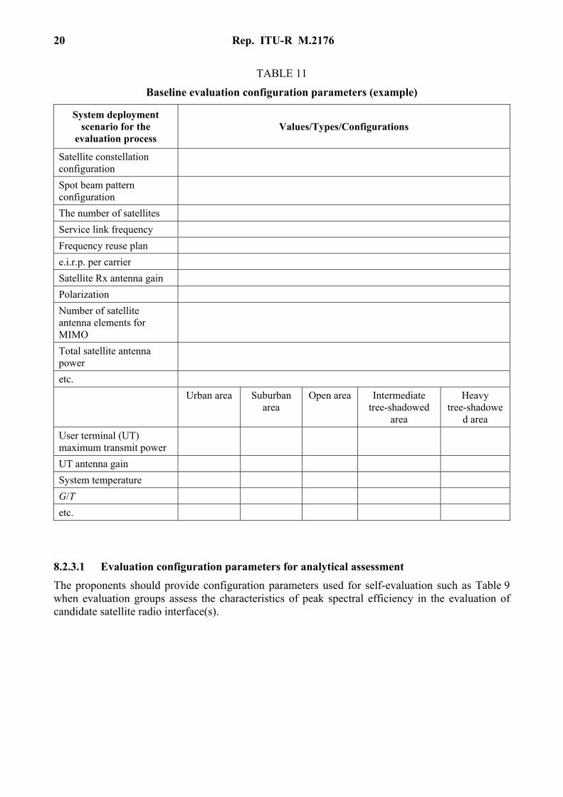
8.2.3 Evaluation configuration
This section contains baseline configuration parameters that shall be applied in analytical and simulation assessment of candidate satellite radio interface(s).
The parameters are solely for the purpose of consistent evaluation of the candidate satellite radio interface(s) and relate only to specific test environments used in these simulations. They should not be considered as the values that must be used in any deployment of any IMT-Advanced system nor should they be taken as the default values for any other or subsequent study in ITU or elsewhere. They do not necessarily themselves constitute any requirements on the implementation of the system.
Evaluation configuration parameters in each test environment depend on the identified satellite system configuration. Therefore, proponents should notice the evaluation configuration parameters such as seen in Tables 11 to 16 in the test environments considered in the satellite system intended to use the proposed RIT/SRITs and then, they should submit the self-evaluation results based on the specific configuration parameters. The information would also help the evaluation process of other evaluation groups.
The specific configuration parameters of examined systems shall be provided by proponents when evaluation groups assess the characteristics of beam spectral efficiency, beam edge user spectral efficiency, control plane latency, user plane latency, mobility, handover interruption time and VoIP capacity in the evaluation of candidate satellite radio interface(s).
20 Rep. ITU-R M.2176
TABLE 11
Baseline evaluation configuration parameters (example)
System deployment scenario for the
evaluation process Values/Types/Configurations
Satellite constellation configuration
Spot beam pattern configuration
The number of satellites
Service link frequency
Frequency reuse plan
e.i.r.p. per carrier
Satellite Rx antenna gain
Polarization
Number of satellite antenna elements for MIMO
Total satellite antenna power
etc.
Urban area Suburban area
Open area Intermediate tree-shadowed
area
Heavy tree-shadowe
d area
User terminal (UT) maximum transmit power
UT antenna gain
System temperature
G/T
etc.
8.2.3.1 Evaluation configuration parameters for analytical assessment
The proponents should provide configuration parameters used for self-evaluation such as Table 9 when evaluation groups assess the characteristics of peak spectral efficiency in the evaluation of candidate satellite radio interface(s).
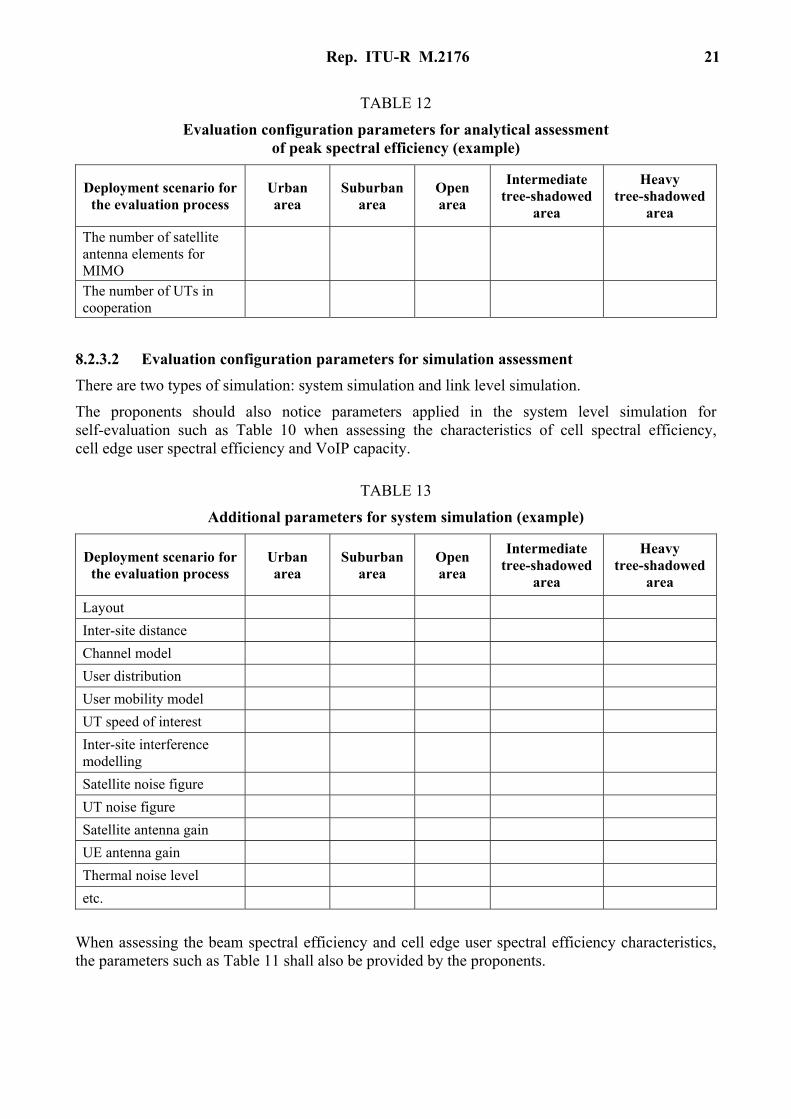
Rep. ITU-R M.2176 21
TABLE 12
Evaluation configuration parameters for analytical assessment of peak spectral efficiency (example)
Deployment scenario for the evaluation process
Urban area
Suburban area
Open area
Intermediate tree-shadowed
area
Heavy tree-shadowed
area
The number of satellite antenna elements for MIMO
The number of UTs in cooperation
8.2.3.2 Evaluation configuration parameters for simulation assessment
There are two types of simulation: system simulation and link level simulation.
The proponents should also notice parameters applied in the system level simulation for self-evaluation such as Table 10 when assessing the characteristics of cell spectral efficiency, cell edge user spectral efficiency and VoIP capacity.
TABLE 13
Additional parameters for system simulation (example)
Deployment scenario for the evaluation process
Urban area
Suburban area
Open area
Intermediate tree-shadowed
area
Heavy tree-shadowed
area
Layout
Inter-site distance
Channel model
User distribution
User mobility model
UT speed of interest
Inter-site interference modelling
Satellite noise figure
UT noise figure
Satellite antenna gain
UE antenna gain
Thermal noise level
etc.
When assessing the beam spectral efficiency and cell edge user spectral efficiency characteristics, the parameters such as Table 11 shall also be provided by the proponents.
22 Rep. ITU-R M.2176
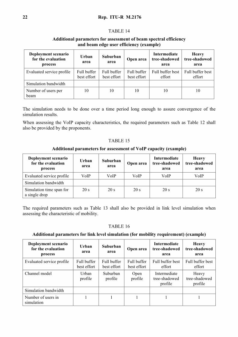
TABLE 14
Additional parameters for assessment of beam spectral efficiency and beam edge user efficiency (example)
Deployment scenario for the evaluation
process
Urban area
Suburban area
Open area Intermediate
tree-shadowed area
Heavy tree-shadowed
area
Evaluated service profile Full buffer best effort
Full buffer best effort
Full buffer best effort
Full buffer best effort
Full buffer best effort
Simulation bandwidth
Number of users per beam
10 10 10 10 10
The simulation needs to be done over a time period long enough to assure convergence of the simulation results.
When assessing the VoIP capacity characteristics, the required parameters such as Table 12 shall also be provided by the proponents.
TABLE 15
Additional parameters for assessment of VoIP capacity (example)
Deployment scenario for the evaluation
process
Urban area
Suburban area
Open area Intermediate
tree-shadowed area
Heavy tree-shadowed
area
Evaluated service profile VoIP VoIP VoIP VoIP VoIP
Simulation bandwidth
Simulation time span for a single drop
20 s 20 s 20 s 20 s 20 s
The required parameters such as Table 13 shall also be provided in link level simulation when assessing the characteristic of mobility.
TABLE 16
Additional parameters for link level simulation (for mobility requirement) (example)
Deployment scenario for the evaluation
process
Urban area
Suburban area
Open area Intermediate
tree-shadowed area
Heavy tree-shadowed
area
Evaluated service profile Full buffer best effort
Full buffer best effort
Full buffer best effort
Full buffer best effort
Full buffer best effort
Channel model Urban profile
Suburban profile
Open profile
Intermediate tree-shadowed
profile
Heavy tree-shadowed
profile
Simulation bandwidth
Number of users in simulation
1 1 1 1 1
Rep. ITU-R M.2176 23
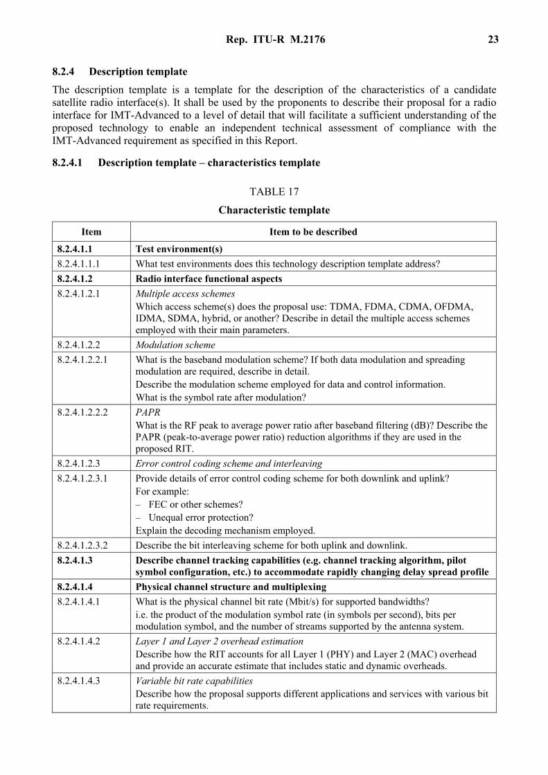
8.2.4 Description template
The description template is a template for the description of the characteristics of a candidate satellite radio interface(s). It shall be used by the proponents to describe their proposal for a radio interface for IMT-Advanced to a level of detail that will facilitate a sufficient understanding of the proposed technology to enable an independent technical assessment of compliance with the IMT-Advanced requirement as specified in this Report.
8.2.4.1 Description template – characteristics template
TABLE 17
Characteristic template
Item Item to be described
8.2.4.1.1 Test environment(s)
8.2.4.1.1.1 What test environments does this technology description template address?
8.2.4.1.2 Radio interface functional aspects
8.2.4.1.2.1 Multiple access schemes Which access scheme(s) does the proposal use: TDMA, FDMA, CDMA, OFDMA, IDMA, SDMA, hybrid, or another? Describe in detail the multiple access schemes employed with their main parameters.
8.2.4.1.2.2 Modulation scheme
8.2.4.1.2.2.1 What is the baseband modulation scheme? If both data modulation and spreading modulation are required, describe in detail. Describe the modulation scheme employed for data and control information. What is the symbol rate after modulation?
8.2.4.1.2.2.2 PAPR What is the RF peak to average power ratio after baseband filtering (dB)? Describe the PAPR (peak-to-average power ratio) reduction algorithms if they are used in the proposed RIT.
8.2.4.1.2.3 Error control coding scheme and interleaving
8.2.4.1.2.3.1 Provide details of error control coding scheme for both downlink and uplink? For example: – FEC or other schemes? – Unequal error protection? Explain the decoding mechanism employed.
8.2.4.1.2.3.2 Describe the bit interleaving scheme for both uplink and downlink.
8.2.4.1.3 Describe channel tracking capabilities (e.g. channel tracking algorithm, pilot symbol configuration, etc.) to accommodate rapidly changing delay spread profile
8.2.4.1.4 Physical channel structure and multiplexing
8.2.4.1.4.1 What is the physical channel bit rate (Mbit/s) for supported bandwidths? i.e. the product of the modulation symbol rate (in symbols per second), bits per modulation symbol, and the number of streams supported by the antenna system.
8.2.4.1.4.2 Layer 1 and Layer 2 overhead estimation Describe how the RIT accounts for all Layer 1 (PHY) and Layer 2 (MAC) overhead and provide an accurate estimate that includes static and dynamic overheads.
8.2.4.1.4.3 Variable bit rate capabilities Describe how the proposal supports different applications and services with various bit rate requirements.
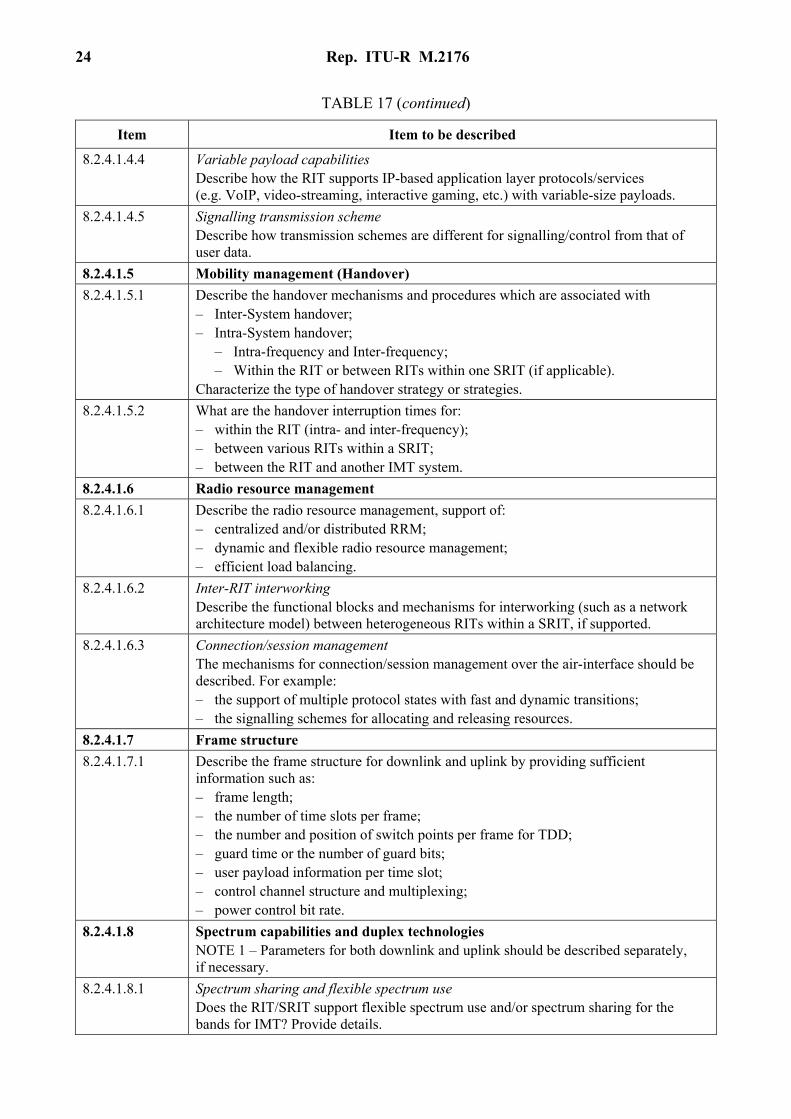
24 Rep. ITU-R M.2176
TABLE 17 (continued)
Item Item to be described
8.2.4.1.4.4 Variable payload capabilities Describe how the RIT supports IP-based application layer protocols/services (e.g. VoIP, video-streaming, interactive gaming, etc.) with variable-size payloads.
8.2.4.1.4.5 Signalling transmission scheme Describe how transmission schemes are different for signalling/control from that of user data.
8.2.4.1.5 Mobility management (Handover)
8.2.4.1.5.1 Describe the handover mechanisms and procedures which are associated with – Inter-System handover; – Intra-System handover; – Intra-frequency and Inter-frequency; – Within the RIT or between RITs within one SRIT (if applicable). Characterize the type of handover strategy or strategies.
8.2.4.1.5.2 What are the handover interruption times for: – within the RIT (intra- and inter-frequency); – between various RITs within a SRIT; – between the RIT and another IMT system.
8.2.4.1.6 Radio resource management
8.2.4.1.6.1 Describe the radio resource management, support of: – centralized and/or distributed RRM; – dynamic and flexible radio resource management; – efficient load balancing.
8.2.4.1.6.2 Inter-RIT interworking Describe the functional blocks and mechanisms for interworking (such as a network architecture model) between heterogeneous RITs within a SRIT, if supported.
8.2.4.1.6.3 Connection/session management The mechanisms for connection/session management over the air-interface should be described. For example: – the support of multiple protocol states with fast and dynamic transitions; – the signalling schemes for allocating and releasing resources.
8.2.4.1.7 Frame structure
8.2.4.1.7.1 Describe the frame structure for downlink and uplink by providing sufficient information such as: – frame length; – the number of time slots per frame; – the number and position of switch points per frame for TDD; – guard time or the number of guard bits; – user payload information per time slot; – control channel structure and multiplexing; – power control bit rate.
8.2.4.1.8 Spectrum capabilities and duplex technologies NOTE 1 – Parameters for both downlink and uplink should be described separately, if necessary.
8.2.4.1.8.1 Spectrum sharing and flexible spectrum use Does the RIT/SRIT support flexible spectrum use and/or spectrum sharing for the bands for IMT? Provide details.
Rep. ITU-R M.2176 25
TABLE 17 (continued)
Item Item to be described
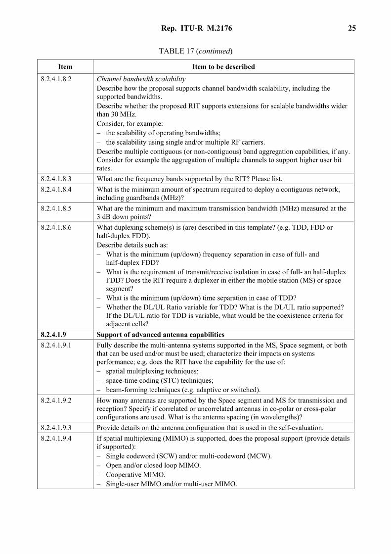
8.2.4.1.8.2 Channel bandwidth scalability Describe how the proposal supports channel bandwidth scalability, including the supported bandwidths. Describe whether the proposed RIT supports extensions for scalable bandwidths wider than 30 MHz. Consider, for example: – the scalability of operating bandwidths; – the scalability using single and/or multiple RF carriers. Describe multiple contiguous (or non-contiguous) band aggregation capabilities, if any. Consider for example the aggregation of multiple channels to support higher user bit rates.
8.2.4.1.8.3 What are the frequency bands supported by the RIT? Please list.
8.2.4.1.8.4 What is the minimum amount of spectrum required to deploy a contiguous network, including guardbands (MHz)?
8.2.4.1.8.5 What are the minimum and maximum transmission bandwidth (MHz) measured at the 3 dB down points?
8.2.4.1.8.6 What duplexing scheme(s) is (are) described in this template? (e.g. TDD, FDD or half-duplex FDD). Describe details such as: – What is the minimum (up/down) frequency separation in case of full- and
half-duplex FDD? – What is the requirement of transmit/receive isolation in case of full- an half-duplex
FDD? Does the RIT require a duplexer in either the mobile station (MS) or space segment?
– What is the minimum (up/down) time separation in case of TDD? – Whether the DL/UL Ratio variable for TDD? What is the DL/UL ratio supported?
If the DL/UL ratio for TDD is variable, what would be the coexistence criteria for adjacent cells?
8.2.4.1.9 Support of advanced antenna capabilities
8.2.4.1.9.1 Fully describe the multi-antenna systems supported in the MS, Space segment, or both that can be used and/or must be used; characterize their impacts on systems performance; e.g. does the RIT have the capability for the use of: – spatial multiplexing techniques; – space-time coding (STC) techniques; – beam-forming techniques (e.g. adaptive or switched).
8.2.4.1.9.2 How many antennas are supported by the Space segment and MS for transmission and reception? Specify if correlated or uncorrelated antennas in co-polar or cross-polar configurations are used. What is the antenna spacing (in wavelengths)?
8.2.4.1.9.3 Provide details on the antenna configuration that is used in the self-evaluation.
8.2.4.1.9.4 If spatial multiplexing (MIMO) is supported, does the proposal support (provide details if supported): – Single codeword (SCW) and/or multi-codeword (MCW). – Open and/or closed loop MIMO. – Cooperative MIMO. – Single-user MIMO and/or multi-user MIMO.
26 Rep. ITU-R M.2176
TABLE 17 (continued)
Item Item to be described
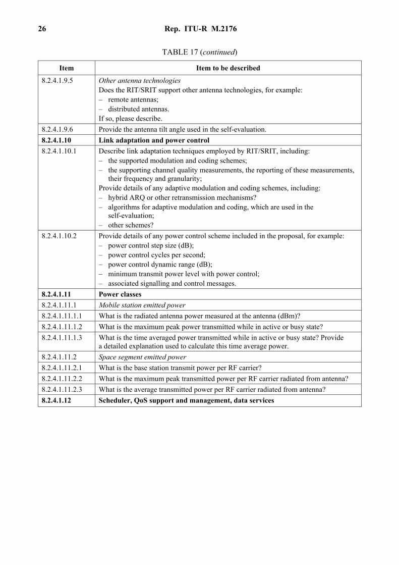
8.2.4.1.9.5 Other antenna technologies Does the RIT/SRIT support other antenna technologies, for example: – remote antennas; – distributed antennas. If so, please describe.
8.2.4.1.9.6 Provide the antenna tilt angle used in the self-evaluation.
8.2.4.1.10 Link adaptation and power control
8.2.4.1.10.1 Describe link adaptation techniques employed by RIT/SRIT, including: – the supported modulation and coding schemes; – the supporting channel quality measurements, the reporting of these measurements,
their frequency and granularity; Provide details of any adaptive modulation and coding schemes, including: – hybrid ARQ or other retransmission mechanisms? – algorithms for adaptive modulation and coding, which are used in the
self-evaluation; – other schemes?
8.2.4.1.10.2 Provide details of any power control scheme included in the proposal, for example: – power control step size (dB); – power control cycles per second; – power control dynamic range (dB); – minimum transmit power level with power control; – associated signalling and control messages.
8.2.4.1.11 Power classes
8.2.4.1.11.1 Mobile station emitted power
8.2.4.1.11.1.1 What is the radiated antenna power measured at the antenna (dBm)?
8.2.4.1.11.1.2 What is the maximum peak power transmitted while in active or busy state?
8.2.4.1.11.1.3 What is the time averaged power transmitted while in active or busy state? Provide a detailed explanation used to calculate this time average power.
8.2.4.1.11.2 Space segment emitted power
8.2.4.1.11.2.1 What is the base station transmit power per RF carrier?
8.2.4.1.11.2.2 What is the maximum peak transmitted power per RF carrier radiated from antenna?
8.2.4.1.11.2.3 What is the average transmitted power per RF carrier radiated from antenna?
8.2.4.1.12 Scheduler, QoS support and management, data services
Rep. ITU-R M.2176 27
TABLE 17 (continued)
Item Item to be described
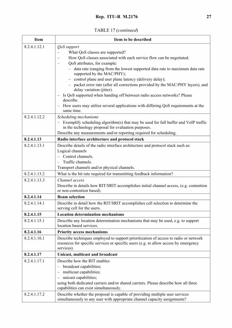
8.2.4.1.12.1 QoS support – What QoS classes are supported? – How QoS classes associated with each service flow can be negotiated. – QoS attributes, for example: – data rate (ranging from the lowest supported data rate to maximum data rate
supported by the MAC/PHY); – control plane and user plane latency (delivery delay); – packet error rate (after all corrections provided by the MAC/PHY layers), and
delay variation (jitter). – Is QoS supported when handing off between radio access networks? Please
describe. – How users may utilize several applications with differing QoS requirements at the
same time.
8.2.4.1.12.2 Scheduling mechanisms – Exemplify scheduling algorithm(s) that may be used for full buffer and VoIP traffic
in the technology proposal for evaluation purposes. Describe any measurements and/or reporting required for scheduling.
8.2.4.1.13 Radio interface architecture and protocol stack
8.2.4.1.13.1 Describe details of the radio interface architecture and protocol stack such as: Logical channels – Control channels. – Traffic channels. Transport channels and/or physical channels.
8.2.4.1.13.2 What is the bit rate required for transmitting feedback information?
8.2.4.1.13.3 Channel access Describe in details how RIT/SRIT accomplishes initial channel access, (e.g. contention or non-contention based).
8.2.4.1.14 Beam selection
8.2.4.1.14.1 Describe in detail how the RIT/SRIT accomplishes cell selection to determine the serving cell for the users.
8.2.4.1.15 Location determination mechanisms
8.2.4.1.15.1 Describe any location determination mechanisms that may be used, e.g. to support location based services.
8.2.4.1.16 Priority access mechanisms
8.2.4.1.16.1 Describe techniques employed to support prioritization of access to radio or network resources for specific services or specific users (e.g. to allow access by emergency services).
8.2.4.1.17 Unicast, multicast and broadcast
8.2.4.1.17.1 Describe how the RIT enables: – broadcast capabilities; – multicast capabilities; – unicast capabilities; using both dedicated carriers and/or shared carriers. Please describe how all three capabilities can exist simultaneously.
8.2.4.1.17.2 Describe whether the proposal is capable of providing multiple user services simultaneously to any user with appropriate channel capacity assignments?
28 Rep. ITU-R M.2176
TABLE 17 (continued)
Item Item to be described
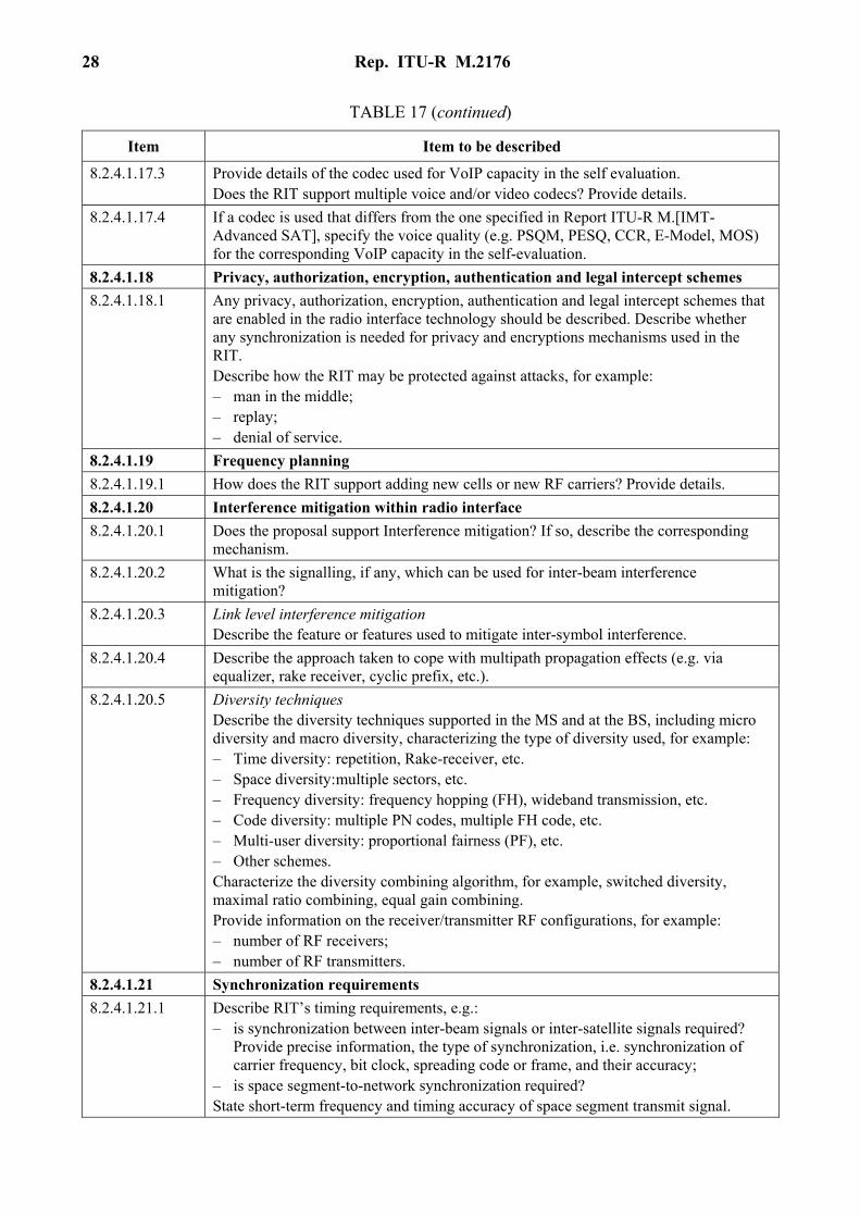
8.2.4.1.17.3 Provide details of the codec used for VoIP capacity in the self evaluation. Does the RIT support multiple voice and/or video codecs? Provide details.
8.2.4.1.17.4 If a codec is used that differs from the one specified in Report ITU-R M.[IMT-Advanced SAT], specify the voice quality (e.g. PSQM, PESQ, CCR, E-Model, MOS) for the corresponding VoIP capacity in the self-evaluation.
8.2.4.1.18 Privacy, authorization, encryption, authentication and legal intercept schemes
8.2.4.1.18.1 Any privacy, authorization, encryption, authentication and legal intercept schemes that are enabled in the radio interface technology should be described. Describe whether any synchronization is needed for privacy and encryptions mechanisms used in the RIT. Describe how the RIT may be protected against attacks, for example: – man in the middle; – replay; – denial of service.
8.2.4.1.19 Frequency planning
8.2.4.1.19.1 How does the RIT support adding new cells or new RF carriers? Provide details.
8.2.4.1.20 Interference mitigation within radio interface
8.2.4.1.20.1 Does the proposal support Interference mitigation? If so, describe the corresponding mechanism.
8.2.4.1.20.2 What is the signalling, if any, which can be used for inter-beam interference mitigation?
8.2.4.1.20.3 Link level interference mitigation Describe the feature or features used to mitigate inter-symbol interference.
8.2.4.1.20.4 Describe the approach taken to cope with multipath propagation effects (e.g. via equalizer, rake receiver, cyclic prefix, etc.).
8.2.4.1.20.5 Diversity techniques Describe the diversity techniques supported in the MS and at the BS, including micro diversity and macro diversity, characterizing the type of diversity used, for example: – Time diversity: repetition, Rake-receiver, etc. – Space diversity: multiple sectors, etc. – Frequency diversity: frequency hopping (FH), wideband transmission, etc. – Code diversity: multiple PN codes, multiple FH code, etc. – Multi-user diversity: proportional fairness (PF), etc. – Other schemes. Characterize the diversity combining algorithm, for example, switched diversity, maximal ratio combining, equal gain combining. Provide information on the receiver/transmitter RF configurations, for example: – number of RF receivers; – number of RF transmitters.
8.2.4.1.21 Synchronization requirements
8.2.4.1.21.1 Describe RIT’s timing requirements, e.g.: – is synchronization between inter-beam signals or inter-satellite signals required?
Provide precise information, the type of synchronization, i.e. synchronization of carrier frequency, bit clock, spreading code or frame, and their accuracy;
– is space segment-to-network synchronization required? State short-term frequency and timing accuracy of space segment transmit signal.
Rep. ITU-R M.2176 29
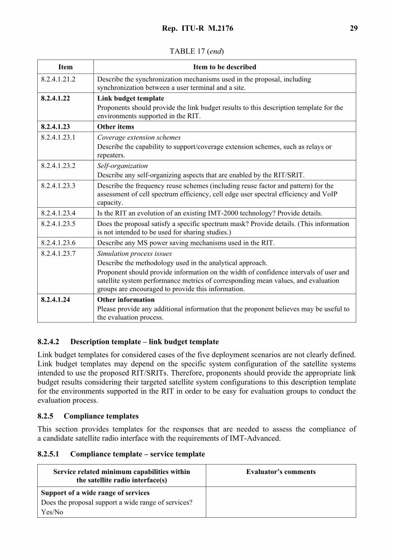
TABLE 17 (end)
Item Item to be described
8.2.4.1.21.2 Describe the synchronization mechanisms used in the proposal, including synchronization between a user terminal and a site.
8.2.4.1.22 Link budget template Proponents should provide the link budget results to this description template for the environments supported in the RIT.
8.2.4.1.23 Other items
8.2.4.1.23.1 Coverage extension schemes Describe the capability to support/coverage extension schemes, such as relays or repeaters.
8.2.4.1.23.2 Self-organization Describe any self-organizing aspects that are enabled by the RIT/SRIT.
8.2.4.1.23.3 Describe the frequency reuse schemes (including reuse factor and pattern) for the assessment of cell spectrum efficiency, cell edge user spectral efficiency and VoIP capacity.
8.2.4.1.23.4 Is the RIT an evolution of an existing IMT-2000 technology? Provide details.
8.2.4.1.23.5 Does the proposal satisfy a specific spectrum mask? Provide details. (This information is not intended to be used for sharing studies.)
8.2.4.1.23.6 Describe any MS power saving mechanisms used in the RIT.
8.2.4.1.23.7 Simulation process issues Describe the methodology used in the analytical approach. Proponent should provide information on the width of confidence intervals of user and satellite system performance metrics of corresponding mean values, and evaluation groups are encouraged to provide this information.
8.2.4.1.24 Other information Please provide any additional information that the proponent believes may be useful to the evaluation process.
8.2.4.2 Description template – link budget template
Link budget templates for considered cases of the five deployment scenarios are not clearly defined. Link budget templates may depend on the specific system configuration of the satellite systems intended to use the proposed RIT/SRITs. Therefore, proponents should provide the appropriate link budget results considering their targeted satellite system configurations to this description template for the environments supported in the RIT in order to be easy for evaluation groups to conduct the evaluation process.
8.2.5 Compliance templates
This section provides templates for the responses that are needed to assess the compliance of a candidate satellite radio interface with the requirements of IMT-Advanced.
8.2.5.1 Compliance template – service template
Service related minimum capabilities within the satellite radio interface(s)
Evaluator’s comments
Support of a wide range of services Does the proposal support a wide range of services? Yes/No
30 Rep. ITU-R M.2176
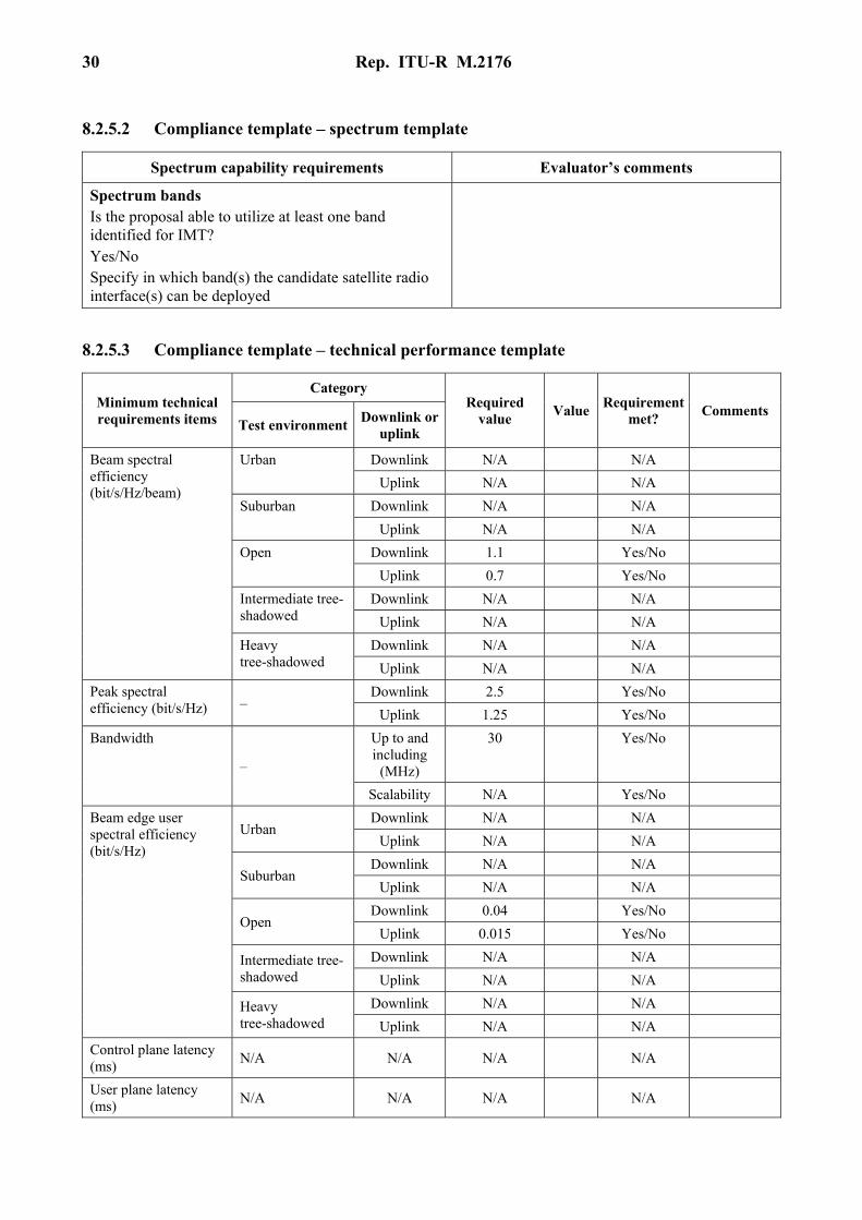
8.2.5.2 Compliance template – spectrum template
Spectrum capability requirements Evaluator’s comments
Spectrum bands Is the proposal able to utilize at least one band identified for IMT? Yes/No Specify in which band(s) the candidate satellite radio interface(s) can be deployed
8.2.5.3 Compliance template – technical performance template
Minimum technical requirements items
Category Required
value Value
Requirement met?
Comments Test environment
Downlink or uplink
Beam spectral efficiency (bit/s/Hz/beam)
Urban Downlink N/A N/A
Uplink N/A N/A
Suburban Downlink N/A N/A
Uplink N/A N/A
Open Downlink 1.1 Yes/No
Uplink 0.7 Yes/No
Intermediate tree-shadowed
Downlink N/A N/A
Uplink N/A N/A
Heavy tree-shadowed
Downlink N/A N/A
Uplink N/A N/A
Peak spectral efficiency (bit/s/Hz) –
Downlink 2.5 Yes/No
Uplink 1.25 Yes/No
Bandwidth
–
Up to and including
(MHz)
30 Yes/No
Scalability N/A Yes/No
Beam edge user spectral efficiency (bit/s/Hz)
Urban Downlink N/A N/A
Uplink N/A N/A
Suburban Downlink N/A N/A
Uplink N/A N/A
Open Downlink 0.04 Yes/No
Uplink 0.015 Yes/No
Intermediate tree-shadowed
Downlink N/A N/A
Uplink N/A N/A
Heavy tree-shadowed
Downlink N/A N/A
Uplink N/A N/A
Control plane latency (ms)
N/A N/A N/A N/A
User plane latency (ms)
N/A N/A N/A N/A
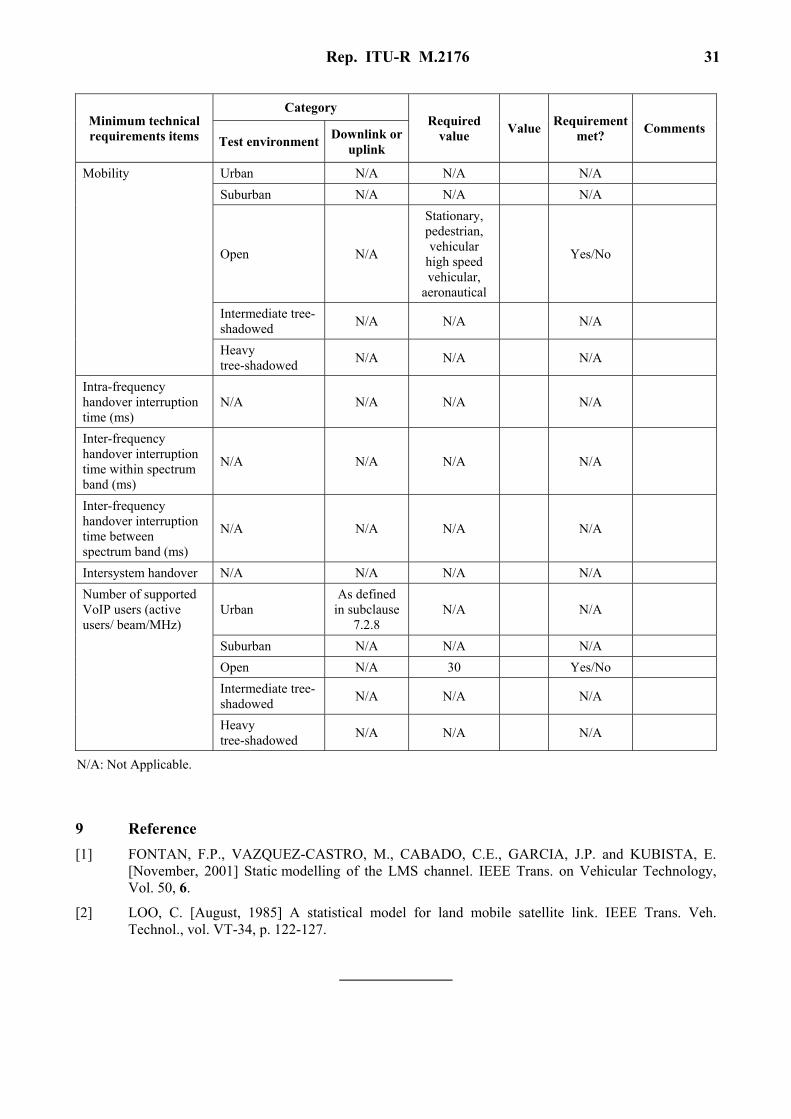
Rep. ITU-R M.2176 31
Minimum technical requirements items
Category Required
value Value
Requirement met?
Comments Test environment
Downlink or uplink
Mobility Urban N/A N/A N/A
Suburban N/A N/A N/A
Open N/A
Stationary, pedestrian, vehicular
high speed vehicular,
aeronautical
Yes/No
Intermediate tree-shadowed
N/A N/A N/A
Heavy tree-shadowed
N/A N/A N/A
Intra-frequency handover interruption time (ms)
N/A N/A N/A N/A
Inter-frequency handover interruption time within spectrum band (ms)
N/A N/A N/A N/A
Inter-frequency handover interruption time between spectrum band (ms)
N/A N/A N/A N/A
Intersystem handover N/A N/A N/A N/A
Number of supported VoIP users (active users/ beam/MHz)
Urban As defined
in subclause 7.2.8
N/A N/A
Suburban N/A N/A N/A
Open N/A 30 Yes/No
Intermediate tree-shadowed
N/A N/A N/A
Heavy tree-shadowed
N/A N/A N/A
N/A: Not Applicable.
9 Reference
[1] FONTAN, F.P., VAZQUEZ-CASTRO, M., CABADO, C.E., GARCIA, J.P. and KUBISTA, E. [November, 2001] Static modelling of the LMS channel. IEEE Trans. on Vehicular Technology, Vol. 50, 6.
[2] LOO, C. [August, 1985] A statistical model for land mobile satellite link. IEEE Trans. Veh. Technol., vol. VT-34, p. 122-127.