Villa VTO (Version 3.3) · 2018-08-10 · numbers to the device. Do not DMZ the device's IP...
100
Villa VTO (Version 3.3) User’s Manual V1.0.0
Transcript of Villa VTO (Version 3.3) · 2018-08-10 · numbers to the device. Do not DMZ the device's IP...

Villa VTO
(Version 3.3)
User’s Manual
V1.0.0

Cybersecurity Recommendations II
Cybersecurity Recommendations
Mandatory actions to be taken towards cybersecurity
1. Change Passwords and Use Strong Passwords:
The number one reason systems get “hacked” is due to having weak or default passwords. It is
recommended to change default passwords immediately and choose a strong password
whenever possible. A strong password should be made up of at least 8 characters and a
combination of special characters, numbers, and upper and lower case letters.
2. Update Firmware
As is standard procedure in the tech-industry, we recommend keeping NVR, DVR, and IP
camera firmware up-to-date to ensure the system is current with the latest security patches and
fixes.
“Nice to have” recommendations to improve your network security
1. Change Passwords Regularly
Regularly change the credentials to your devices to help ensure that only authorized users are
able to access the system.
2. Change Default HTTP and TCP Ports:
● Change default HTTP and TCP ports for systems. These are the two ports used to
communicate and to view video feeds remotely.
● These ports can be changed to any set of numbers between 1025-65535. Avoiding the default
ports reduces the risk of outsiders being able to guess which ports you are using.
3. Enable HTTPS/SSL:
Set up an SSL Certificate to enable HTTPS. This will encrypt all communication between your
devices and recorder.
4. Enable IP Filter:
Enabling your IP filter will prevent everyone, except those with specified IP addresses, from
accessing the system.
5. Change ONVIF Password:
On older IP Camera firmware, the ONVIF password does not change when you change the
system’s credentials. You will need to either update the camera’s firmware to the latest revision
or manually change the ONVIF password.
6. Forward Only Ports You Need:

Cybersecurity Recommendations III
● Only forward the HTTP and TCP ports that you need to use. Do not forward a huge range of
numbers to the device. Do not DMZ the device's IP address.
● You do not need to forward any ports for individual cameras if they are all connected to a
recorder on site; just the NVR is needed.
7. Disable Auto-Login on SmartPSS:
Those using SmartPSS to view their system and on a computer that is used by multiple people
should disable auto-login. This adds a layer of security to prevent users without the appropriate
credentials from accessing the system.
8. Use a Different Username and Password for SmartPSS:
In the event that your social media, bank, email, etc. account is compromised, you would not
want someone collecting those passwords and trying them out on your video surveillance
system. Using a different username and password for your security system will make it more
difficult for someone to guess their way into your system.
9. Limit Features of Guest Accounts:
If your system is set up for multiple users, ensure that each user only has rights to features and
functions they need to use to perform their job.
10. UPnP:
● UPnP will automatically try to forward ports in your router or modem. Normally this would be a
good thing. However, if your system automatically forwards the ports and you leave the
credentials defaulted, you may end up with unwanted visitors.
● If you manually forwarded the HTTP and TCP ports in your router/modem, this feature should
be turned off regardless. Disabling UPnP is recommended when the function is not used in real
applications.
11. SNMP:
Disable SNMP if you are not using it. If you are using SNMP, you should do so only temporarily,
for tracing and testing purposes only.
12. Multicast:
Multicast is used to share video streams between two recorders. Currently there are no known
issues involving Multicast, but if you are not using this feature, deactivation can enhance your
network security.
13. Check the Log:
If you suspect that someone has gained unauthorized access to your system, you can check the
system log. The system log will show you which IP addresses were used to login to your system
and what was accessed.
14. Physically Lock Down the Device:

Cybersecurity Recommendations IV
Ideally, you want to prevent any unauthorized physical access to your system. The best way to
achieve this is to install the recorder in a lockbox, locking server rack, or in a room that is behind
a lock and key.
15. Connect IP Cameras to the PoE Ports on the Back of an NVR:
Cameras connected to the PoE ports on the back of an NVR are isolated from the outside world
and cannot be accessed directly.
16. Isolate NVR and IP Camera Network
The network your NVR and IP camera resides on should not be the same network as your public
computer network. This will prevent any visitors or unwanted guests from getting access to the
same network the security system needs in order to function properly.

Foreword V
Foreword
General
This document mainly introduces function, structure, networking, mounting process, debugging
process, WEB interface operation and technical parameters of villa VTO products, which are
used with version 3.3 WEB interface.
Models
VTO6000A, VTO6110B, VTO6110BW, VTO6210B, VTO6000C, VTO6000CM, VTO6100C,
VTO2000A, VTO2000A-2 and VTO2101E-P.
Device Upgrade
Please don’t cut off power supply during device upgrade. Power supply can be cut off only after
the device has completed upgrade and has rebooted.
General Description about Keys
OK: it is used to save the settings.
Default: it is used to restore all parameters at the present interface to default system
configurations.
Refresh: restore parameters at the present interface to present system configurations.
Safety Instructions
The following categorized signal words with defined meaning might appear in the Manual.
Signal Words Meaning
Indicates a high potential hazard which, if not avoided, will result in
death or serious injury.
Indicates a medium or low potential hazard which, if not avoided,
could result in slight or moderate injury.
Indicates a potential risk which, if not avoided, could result in
property damage, data loss, lower performance, or unpredictable
result.
Provides methods to help you solve a problem or save you time.
Provides additional information as the emphasis and supplement to
the text.

Foreword VI
Revision History
No. Version Revision Content Release Date
1 V1.0.0 First release 2017.12.31
Privacy Protection Notice
As the device user or data controller, you might collect personal data of others' such as face,
fingerprints, car plate number, Email address, phone number, GPS and so on. You need to be
in compliance with the local privacy protection laws and regulations to protect the legitimate
rights and interests of other people by implementing measures include but not limited to:
providing clear and visible identification to inform data subject the existence of surveillance
area and providing related contact.
About the Manual
The Manual is for reference only. If there is inconsistency between the Manual and the
actual product, the actual product shall prevail.
We are not liable for any loss caused by the operations that do not comply with the Manual.
The Manual would be updated according to the latest laws and regulations of related
regions. For detailed information, see the paper User's Manual, CD-ROM, QR code or our
official website. If there is inconsistency between paper User's Manual and the electronic
version, the electronic version shall prevail.
All the designs and software are subject to change without prior written notice. The product
updates might cause some differences between the actual product and the Manual. Please
contact the customer service for the latest program and supplementary documentation.
There still might be deviation in technical data, functions and operations description, or
errors in print. If there is any doubt or dispute, please refer to our final explanation.
Upgrade the reader software or try other mainstream reader software if the Guide (in PDF
format) cannot be opened.
All trademarks, registered trademarks and the company names in the Manual are the
properties of their respective owners.
Please visit our website, contact the supplier or customer service if there is any problem
occurred when using the device.
If there is any uncertainty or controversy, please refer to our final explanation.

Important Safeguards and Warnings VII
Important Safeguards and Warnings
The following description is the correct application method of the device. Please read the
manual carefully before use, in order to prevent danger and property loss. Strictly conform to
the manual during application and keep it properly after reading.
Operating Requirement
Please don’t place and install the device in an area exposed to direct sunlight or near heat
generating device.
Please don’t install the device in a humid, dusty or fuliginous area.
Please keep its horizontal installation, or install it at stable places, and prevent it from
falling.
Please don’t drip or splash liquids onto the device; don’t put on the device anything filled
with liquids, in order to prevent liquids from flowing into the device.
Please install the device at well-ventilated places; don’t block its ventilation opening.
Use the device only within rated input and output range.
Please don’t dismantle the device arbitrarily.
Power Requirement
The product shall use electric wires (power wires) recommended by this area, which shall
be used within its rated specification!
Please use power supply that meets SELV (safety extra low voltage) requirements, and
supply power with rated voltage that conforms to Limited Power Source in IEC60950-1. For
specific power supply requirements, please refer to device labels.
Appliance coupler is a disconnecting device. During normal use, please keep an angle that
facilitates operation.

Table of Contents VIII
Table of Contents
Cybersecurity Recommendations ........................................................................................................ II
Foreword ................................................................................................................................................. V
Important Safeguards and Warnings ................................................................................................. VII
1 Product Overview ............................................................................................................................... 1
Product Profile ............................................................................................................................... 1
Product Function ........................................................................................................................... 1
2 Product Structure ............................................................................................................................... 3
VTO6000A..................................................................................................................................... 3
2.1.1 Front Panel ......................................................................................................................... 3
2.1.2 Rear Panel .......................................................................................................................... 3
VTO6110B/VTO6110BW/VTO6210B ............................................................................................ 4
2.2.1 Front Panel ......................................................................................................................... 4
2.2.2 Rear Panel .......................................................................................................................... 5
VTO6000C/VTO6000CM/VTO6100C ........................................................................................... 7
2.3.1 Front Panel ......................................................................................................................... 7
2.3.2 Rear Panel .......................................................................................................................... 8
VTO2000A/VTO2000A-2 .............................................................................................................. 9
2.4.1 Front Panel ......................................................................................................................... 9
2.4.2 Rear Panel ........................................................................................................................ 10
VTO2101E-P ............................................................................................................................... 12
2.5.1 Front Panel ....................................................................................................................... 12
2.5.2 Rear Panel ........................................................................................................................ 13
3 Networking Diagram ......................................................................................................................... 15
VTO6000A/VTO6110B/VTO6110BW/VTO6210B/VTO6000C/VTO6000CM/VTO6100C/VTO2000A/
VTO2101E-P ..................................................................................................................................... 15
3.1.1 One-to-one Scene ............................................................................................................ 15
3.1.2 One-to-many Scene.......................................................................................................... 15
3.1.3 Group Call Scene ............................................................................................................. 16
VTO2000A-2 ............................................................................................................................... 17
3.2.1 One-to-one Scene ............................................................................................................ 17
3.2.2 Group Call Scene ............................................................................................................. 17
4 Device Mounting .................................................................................................................................. 19
Mounting Flow Chart ................................................................................................................... 19
Open-case Inspection ................................................................................................................. 19
Mounting Requirement ................................................................................................................ 20
Device Mounting ......................................................................................................................... 20
4.4.1 VTO6000A ........................................................................................................................ 20
4.4.2 VTO6110B, VTO6210B and VTO6110BW ....................................................................... 21
4.4.3 VTO6000C, VTO6000CM and VTO6100C ...................................................................... 22
4.4.4 VTO2000A/VTO2000A-2 .................................................................................................. 23

Table of Contents IX
4.4.5 VTO2101E-P..................................................................................................................... 26
5 Device Debugging ............................................................................................................................... 29
Debugging Settings ..................................................................................................................... 29
5.1.1 VTO Settings..................................................................................................................... 29
5.1.2 VTH Config ....................................................................................................................... 37
Debugging Verification ................................................................................................................ 43
5.2.1 VTO Calls VTH ................................................................................................................. 43
5.2.2 VTH Monitors VTO ........................................................................................................... 43
6 Basic Function .................................................................................................................................. 45
Call Function ............................................................................................................................... 45
6.1.1 Single Call of VTH ............................................................................................................ 45
6.1.2 Group Call ......................................................................................................................... 45
Unlock Function .......................................................................................................................... 46
6.2.1 Remote Unlock at VTH/VTS ............................................................................................. 46
6.2.2 Open Door at WEB Interface ............................................................................................ 46
6.2.3 Unlock with IC Card .......................................................................................................... 47
6.2.4 Unlock with Exit Button ..................................................................................................... 47
Issue Card ................................................................................................................................... 47
Monitoring Function .................................................................................................................... 48
Tamper Switch ............................................................................................................................. 49
Restore Backup........................................................................................................................... 49
7 WEB Config ....................................................................................................................................... 51
Initialization ................................................................................................................................. 51
Reset the Password .................................................................................................................... 52
System Login .............................................................................................................................. 54
User Manager ............................................................................................................................. 55
7.4.1 Add User ........................................................................................................................... 55
7.4.2 Modify User ....................................................................................................................... 56
7.4.3 Delete User ....................................................................................................................... 58
Network Parameter Config.......................................................................................................... 58
7.5.1 Network Config ................................................................................................................. 58
7.5.2 SIP Server Config ............................................................................................................. 59
7.5.3 FTP Server ........................................................................................................................ 60
7.5.4 Port Config ........................................................................................................................ 60
7.5.5 DDNS Server .................................................................................................................... 61
7.5.6 HTTPS Setting .................................................................................................................. 62
7.5.7 UPnP Config ..................................................................................................................... 63
7.5.8 IP Purview ......................................................................................................................... 65
LAN Config .................................................................................................................................. 67
Local Parameter Config .............................................................................................................. 68
7.7.1 Local Config ...................................................................................................................... 68
7.7.2 A&C Manager ................................................................................................................... 68
7.7.3 Talk Manager .................................................................................................................... 70
7.7.4 System Time ..................................................................................................................... 71
7.7.5 Config Manager ................................................................................................................ 72
7.7.6 Device Manager ................................................................................................................ 72
7.7.1 Outdoor Station Manager ................................................................................................. 72

Table of Contents X
7.7.2 Indoor Station Manager .................................................................................................... 74
7.7.3 Config Manager ................................................................................................................ 76
7.7.4 Card Manager ................................................................................................................... 77
Video Set ..................................................................................................................................... 79
7.8.1 Video Set .......................................................................................................................... 79
7.8.2 Audio Set........................................................................................................................... 80
IPC Information ........................................................................................................................... 81
7.9.1 Add One IPC ..................................................................................................................... 81
7.9.2 Delete ................................................................................................................................ 82
7.9.3 Batch Import ..................................................................................................................... 83
7.9.4 Batch Export ..................................................................................................................... 83
Info Search ................................................................................................................................ 83
7.10.1 Call History ..................................................................................................................... 83
7.10.2 Alarm Record .................................................................................................................. 83
7.10.3 VTO Unlock Record ........................................................................................................ 84
Reboot Device ........................................................................................................................... 84
Logout ....................................................................................................................................... 84
8 FAQ ..................................................................................................................................................... 86
Technical Parameters ..................................................................................................... 87
Appendix 1.1 VTO6000A .................................................................................................................. 87
Appendix 1.2 VTO6110B, VTO6110BW and VTO6210B ................................................................. 87
Appendix 1.3 VTO6000C, VTO6000CM and VTO6100C ................................................................. 88
Appendix 1.4 VTO2000A .................................................................................................................. 88
Appendix 1.5 VTO2000A-2 ............................................................................................................... 89
Accessory Specification ................................................................................................ 90
Appendix 2.1 Specification of Network Cable ................................................................................... 90
Appendix 2.2 Specification of Extension Power Cord ...................................................................... 90
Appendix 2.3 Specification of Embedded Box .................................................................................. 90

Fout! Gebruik het tabblad Start om 标题 1 toe te passen op de tekst die u
hier wilt weergeven. 1
1 Product Overview
Product Profile
Villa VTO (hereinafter referred to as VTO) combines with VTH, VTS and platform to establish a
video intercom system. Support video call between a visitor and a resident, group call,
emergency call, unlock, video preview and record search. It is mainly applied in villa system,
and matched with management platform to realize all-round anti-theft, disaster prevention and
monitoring function.
Product Function
Video Intercom
Call VTH users and realize video talk.
Group Call
Call multiple VTH users at one VTO simultaneously.
Be Monitored
VTH or Management Center can monitor VTO image, and support max. 6-channel video
stream monitoring.
Emergency Call
Press the key to call the Center in case of an emergency.
Auto Snapshot
Snapshot pictures automatically during unlock or talk, and store them in FTP.
Unlock
Realize unlock with card, unlock with password and remote unlock.
Alarm
Support tamper alarm, door sensor alarm and alarm of unlock with duress password.
Meanwhile, report the alarm info to Management Center.

Fout! Gebruik het tabblad Start om 标题 1 toe te passen op de tekst die u
hier wilt weergeven. 2
Record Search
Search call records, alarm records and unlock records.

Fout! Gebruik het tabblad Start om 标题 1 toe te passen op de tekst die u hier
wilt weergeven. 3
2 Product Structure
VTO6000A
2.1.1 Front Panel
VTO6000A
Table 2-1 VTO6000A
No. Name Description
1 Fill-in light Provide fill-in light for camera in case of insufficient light.
2 Camera Monitor the door area.
3 Call key Call management center or VTH.
4 Loudspeaker Audio output.
5 MIC Audio input.
2.1.2 Rear Panel
VTO6000A
Table 2-2 VTO6000A
No. Name Description

Fout! Gebruik het tabblad Start om 标题 1 toe te passen op de tekst die u hier
wilt weergeven. 4
No. Name Description
1 Power port Connect 12V DC power supply.
2 RS485 port Connect extended module of access control.
3 Network port Insert network cable (RJ45 plug).
VTO6110B/VTO6110BW/VTO6210B
2.2.1 Front Panel
VTO6110B/VTO6110BW/VTO6210B
Table 2-3 VTO6110B/VTO6110BW/VTO6210B
No. Name Description
1 Fill-in light Provide fill-in light for camera in case of insufficient light.
2 Camera Monitor the door area.
3 Card
swiping area
Authorize IC card and open the door with IC card.
Make sure that extended module of access control has been
connected.
4 Call key Call management center or VTH.

Fout! Gebruik het tabblad Start om 标题 1 toe te passen op de tekst die u hier
wilt weergeven. 5
2.2.2 Rear Panel
VTO6110B/VTO6110BW
Table 2-4 VTO6110B/VTO6110BW
No. Name Description
1 Tamper
switch
When VTO is detached from the wall forcibly, give out alarm sound and
report alarm info to management center.
2 Network port Insert network cable (RJ45 plug).
3 Power port Connect 12V DC power supply.
4 RS485 port Connect extended module of access control.
5 Loudspeaker Audio output.
VTO6210B

Fout! Gebruik het tabblad Start om 标题 1 toe te passen op de tekst die u hier
wilt weergeven. 6
Table 2-5 VTO6210B
No. Name Description
1 Tamper
switch
When VTO is detached from the wall forcibly, give out alarm sound and
report alarm info to management center.
2 Network port Insert network cable (RJ45 plug).
3 Power port Connect 12V DC power supply.
4 10-core port
Provide lock port, door sensor feedback port and exit button port
to connect electric control lock, solenoid lock and exit button.
Wiring method is shown in Figure 2-6 and Figure 2-7.
Provide a reserved port, to connect extended module of access
control.
5 Loudspeaker Audio output.
Electric Lock
Solenoid Lock

Fout! Gebruik het tabblad Start om 标题 1 toe te passen op de tekst die u hier
wilt weergeven. 7
VTO6000C/VTO6000CM/VTO6100C
2.3.1 Front Panel
VTO6000C and VTO6000CM
VTO6100C
Table 2-6 VTO6000C/VTO6000CM/VTO6100C
No. Name Description
1 Fill-in light Provide fill-in light for camera in case of insufficient light.
2 Camera Monitor the door area.
3 Card
swiping area
Authorize IC card (card issuing function) and open the door with IC
card.
Only VTO6100C supports to exit with IC card. Silkscreen icon of card
swiping area may have different positions; the actual product shall
prevail. This schematic diagram is only for your reference.
4 Call key
Call management center or VTH.
Blue solid light: VTO is in standby status.
Blue flashing light: VTO is calling or talking.
Yellow: it is unlocked with IC card or there is a problem in calling.

Fout! Gebruik het tabblad Start om 标题 1 toe te passen op de tekst die u hier
wilt weergeven. 8
2.3.2 Rear Panel
VTO6000C/VTO6000CM/VTO6100C
Table 2-7 VTO6000C/VTO6000CM/VTO6100C
No. Name Description
1 Network port Insert network cable (RJ45 plug).
2 Power port Connect 12V DC power supply.
3 Debugging port It is used by engineering personnel during debugging.
4 Green plug port 1 Provide lock port, door sensor feedback port and exit button port
to connect electric control lock, solenoid lock and exit button.
Wiring method is shown in Fout! Verwijzingsbron niet
gevonden. and Fout! Verwijzingsbron niet gevonden..
5 Green plug port 2

Fout! Gebruik het tabblad Start om 标题 1 toe te passen op de tekst die u hier
wilt weergeven. 9
VTO2000A/VTO2000A-2
2.4.1 Front Panel
VTO2000A/VTO2000A-2
Table 2-8 VTO2000A/VTO2000A-2
No. Name Description
1 MIC Audio input.
2 Camera Monitor the door area.
3 Fill-in light Provide fill-in light for camera in case of insufficient light.
4 Loudspeaker Audio output.
5 User directory Set user info.
6 Call key Call management center or VTH.

Fout! Gebruik het tabblad Start om 标题 1 toe te passen op de tekst die u hier
wilt weergeven. 10
2.4.2 Rear Panel
VTO2000A
Table 2-9 VTO2000A
No. Name Description
1 Camera angle
adjusting column Adjust camera angle.
2 Tamper switch When VTO is detached from the wall forcibly, give out alarm sound
and report alarm info to management center.
3 Network port Connect network cable (RJ45 plug) with adapter cable.
4 User port
Provide power port, lock port, door sensor feedback port and exit
button port to connect power supply, electric control lock, solenoid
lock and exit button. Wiring method is shown in Figure 2-15 and
Figure 2-16.
5 Debugging port It is used by engineering personnel during debugging.

Fout! Gebruik het tabblad Start om 标题 1 toe te passen op de tekst die u hier
wilt weergeven. 11
VTO2000A-2
Table 2-10 VTO2000A-2
No. Name Description
1 Camera angle
adjusting column Adjust camera angle.
2 Tamper switch When VTO is detached from the wall forcibly, give out alarm sound
and report alarm info to management center.
3 User port
Provide power port, 2-wire port, lock port, door sensor feedback
port and exit button port to connect power supply, 2-wire VTH,
electric control lock, solenoid lock and exit button. Wiring method
is shown in Figure 2-18 and Figure 2-19.
4 Debugging port It is used by engineering personnel during debugging.

Fout! Gebruik het tabblad Start om 标题 1 toe te passen op de tekst die u hier
wilt weergeven. 12
VTO2101E-P
2.5.1 Front Panel
Front panel of the device is shown in Figure 2-20. Please refer to Table 2-11 for description about all
components of front panel.

Fout! Gebruik het tabblad Start om 标题 1 toe te passen op de tekst die u hier
wilt weergeven. 13
Table 2-11
Name Description
Microphone Audio input.
Pinhole Camera Monitor the door area.
IR Fill Light Provide fill light for camera in dark environment.
Photosensitive Switch Measure light intensity automatically.
Key Make a call.
Speaker Audio output.
2.5.2 Rear Panel
Rear panel of the device is shown in Figure 2-21, cable port is shown in Figure 2-22 and port
description is shown in Table 2-12.

Fout! Gebruik het tabblad Start om 标题 1 toe te passen op de tekst die u hier
wilt weergeven. 14
Table 2-12
Pin Mark Description
NO Normally open port of lock
NC Normally closed port of lock
COM Public port of lock
ALARM IN Ground
+12V DC12V power port
GND Door sensor feedback
RS485A RS485 communication port
RS485B

Fout! Gebruik het tabblad Start om 标题 1 toe te passen op de tekst die u hier
wilt weergeven. 15
3 Networking Diagram
VTO6000A/VTO6110B/VTO6110BW/VTO6210B/VTO60
00C/VTO6000CM/VTO6100C/VTO2000A/VTO2101E-P
3.1.1 One-to-one Scene
Villa VTO connects with VTH directly. A visitor presses call key on villa VTO to call the resident
(VTH) or Management Center. Take digital villa VTO VTO6110BW for example; its networking
diagram is shown in Figure 3-1.
3.1.2 One-to-many Scene
Generally, unit VTO is installed at the gate of unit building, whereas villa VTO is installed at the
resident’s gate. The operation process is as follows.
The visitor calls any resident with unit VTO.
The resident’s VTH rings. After unlocking, the visitor goes into the apartment building.
Call the resident with villa VTO, and ask the resident to unlock the house.
Take digital villa VTO6110BW for example; its networking diagram is shown in Figure 3-2.

Fout! Gebruik het tabblad Start om 标题 1 toe te passen op de tekst die u hier
wilt weergeven. 16
3.1.3 Group Call Scene
When the visitor presses call key on villa VTO, multiple VTHs ring at the same time; the
resident can pick up, hang up or unlock on any VTH.
Take digital villa VTO6110BW for example; its networking diagram is shown in Figure 3-3.
VTH consists of master VTH and extension VTH. There is 1 master VTH at most and 5
extension VTHs at most.

Fout! Gebruik het tabblad Start om 标题 1 toe te passen op de tekst die u hier
wilt weergeven. 17
VTO2000A-2
3.2.1 One-to-one Scene
The visitor presses call key to call the resident (VTH) or Management Center, as shown in
Figure 3-4.
3.2.2 Group Call Scene
When the visitor presses call key on villa VTO, multiple VTHs ring at the same time; the
resident can pick up, hang up or unlock on any VTH, as shown in Figure 3-5.
VTH consists of master VTH and extension VTH. There is 1 master VTH at most and 4
extension VTHs at most.

Fout! Gebruik het tabblad Start om 标题 1 toe te passen op de tekst die u hier
wilt weergeven. 18

Fout! Gebruik het tabblad Start om 标题 1 toe te passen op de tekst die u hier
wilt weergeven. 19
4 Device Mounting
Mounting Flow Chart
VTO mounting flow chart is shown in Figure 4-1. Please install VTO in the following steps.
For cable connection, please refer to “2 Product Structure”.
For device mounting, please refer to “4.4 Device Mounting”.
Open-case Inspection
Please carry out open-case inspection when receiving the device. Please timely contact our
after-sales service personnel in case of any problems.
Sequence Item Content
1 Overall Appearance Inspect whether there are obvious damages.

Fout! Gebruik het tabblad Start om 标题 1 toe te passen op de tekst die u hier
wilt weergeven. 20
Sequence Item Content
package Package Inspect whether there are accidental impacts.
Fittings Inspect whether fittings are complete.
2 Model
and label
Device model Inspect whether it is consistent with order
contract.
Label on the
device
Inspect whether it is torn or damaged.
Don’t tear or discard the label, otherwise warranty
service won’t be provided. When dialing our
after-sales hotline, please provide serial number
of the product.
3 Device Appearance Inspect whether there are obvious damages.
Mounting Requirement
Don’t install VTO in bad environment, such as condensation, high temperature, stained,
dusty, chemically corrosive, direct sunshine or unshielded environment.
Engineering mounting and debugging shall be done by professional teams. Please don’t
dismantle or repair arbitrarily in case of device failure.
Device Mounting
4.4.1 VTO6000A
Before installing the bracket or flush mount box, cables in the wall shall be led through the
bracket or flush mount box.
Mount the metal bracket into wall groove.
Connect cables. Please refer to “2.1.2 Rear Panel” for details.
Put the bare device onto the metal bracket; ensure the device bottom clings to metal
bracket bottom.
Fix the bare device onto the metal bracket with ST3×10 screws.

Fout! Gebruik het tabblad Start om 标题 1 toe te passen op de tekst die u hier
wilt weergeven. 21
4.4.2 VTO6110B, VTO6210B and VTO6110BW
Before installing the bracket or flush mount box, cables in the wall shall be led through the
bracket or flush mount box.
Mounting method of VTO6110B, VTO6210B and VTO6110BW is the same. Take “VTO6210B”
for example.
Fix the mounting bracket onto the wall.
1. Fix the bracket onto 86 box with M4 screws. Screw holes are located in Points 3 as
shown in the figure.
2. To strengthen product firmness, tighten it with ST3.0 screws in Points 4 as shown
in the figure.
Connect cables. Please refer to “2.2.2 Rear Panel” for details.
Put the bare device onto the mounting bracket; fit the upper edge first and then push
the lower edge gently.
Fix the whole device onto the bracket with M3 screws.

Fout! Gebruik het tabblad Start om 标题 1 toe te passen op de tekst die u hier
wilt weergeven. 22
4.4.3 VTO6000C, VTO6000CM and VTO6100C
Before installing the bracket or flush mount box, cables in the wall shall be led through the
bracket or flush mount box.
Try not to install VTO6100C onto an iron door directly. Otherwise, signals may be shielded
and card induction may be poor.
Dismantle M3 screws at the bottom of VTO and take off the decorative cap.
Connect cables. Please refer to “2.3.2 Rear Panel” for details.
Fix the bare device onto 86 box with M4 screws. Screw holes are located in Points 3 as
shown in the figure.
To strengthen product firmness, after 86 box is in place, tighten it with ST3.0 screws in
Points 6 as shown in the figure.
Install the decorative cap onto the bare device, and fix it with M3 screws.

Fout! Gebruik het tabblad Start om 标题 1 toe te passen op de tekst die u hier
wilt weergeven. 23
4.4.4 VTO2000A/VTO2000A-2
VTO2000A and VTO2000A-2 devices support the same mounting method and process. Take
“VTO2000A” for example.
Surface Mounting
Drill holes according to hole positions of metal bracket, and put expansion pipe in
place.
Connect cables. Please refer to “2.4.2 Rear Panel” for details.
Fix metal bracket onto the wall with ST3×18 screws.

Fout! Gebruik het tabblad Start om 标题 1 toe te passen op de tekst die u hier
wilt weergeven. 24
Fix the bare device onto metal bracket with M3×6 screws.

Fout! Gebruik het tabblad Start om 标题 1 toe te passen op de tekst die u hier
wilt weergeven. 25
Flush Mounting
Dig a hole in the wall, embed flush mounting box into the wall, and ensure that box
edge clings to the wall.
Hole dimension is 117mm×128mm×80mm.
During flush mounting, lead cables out from the wall.
Connect cables. Please refer to “2.4.2 Rear Panel” for details.
Fix the bare device onto the box with M3×8 screws.

Fout! Gebruik het tabblad Start om 标题 1 toe te passen op de tekst die u hier
wilt weergeven. 26
4.4.5 VTO2101E-P
Dimensional Drawing
Dimensional drawing is shown in Figure 4-10.

Fout! Gebruik het tabblad Start om 标题 1 toe te passen op de tekst die u hier
wilt weergeven. 27
Mounting Steps
Its mounting is shown in Figure 4-11.
Drill holes in mounting surface (such as wall) according to hole positions around
mounting bracket.
Fix the mounting bracket with four ST3*18 screws.
Match front and rear panel components with metal protective cover, and pre-assemble
them onto the mounting bracket.
Adjust the angle of front and rear panel components.
Press down front and rear panel components, as well as mounting bracket.
Fix the metal protective cover and mounting bracket with H-type M4×18 screws.
During mounting, it is recommended that center point of the device should be 1.4m~1.6m
above the ground.

Fout! Gebruik het tabblad Start om 标题 1 toe te passen op de tekst die u hier
wilt weergeven. 28
After installation, you can see Figure 4-12.

Fout! Gebruik het tabblad Start om 标题 1 toe te passen op de tekst die u hier
wilt weergeven. 29
5 Device Debugging
Carry out debugging to ensure that the device can realize basic network access, call and
monitoring functions after installation. Before debugging, please check whether the
following work has been completed.
Check whether there is short circuit or open circuit. Power on the device only after the
circuit is confirmed to be normal.
IP and no. (or room no.) of every VTO and VTH have been planned.
Confirm deployment position of SIP server.
Debugging Settings
This device shall be used with SIP VTH device.
Every VTO and VTH in the network shall be debugged.
5.1.1 VTO Settings
Initialization
For the first time, please initialize login password.
Please ensure that default IP addresses of PC and VTO are in the same network segment.
Default IP address of VTO is 192.168.1.110.
Connect VTO power and boot up.
Enter default IP address of VTO at the address bar of PC browser, and press [Enter]
key. The system displays “Setting” interface, as shown in Figure 5-1.

Fout! Gebruik het tabblad Start om 标题 1 toe te passen op de tekst die u hier
wilt weergeven. 30
Enter “New Password” and “Confirm”, and click “Next”.
The system displays “Protect” interface, as shown in Figure 5-2.
This password is used to login WEB interface. It shall be at least 8 characters, and shall
include at least two types of number, letter and symbol.
Select “Email” and enter your Email address.
This Email address is used to reset the password, so it is recommended that it should
be set.
Click “Next”.
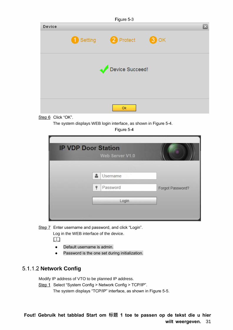
The system displays “OK” interface, as shown in Figure 5-3, and shows “Device
succeed!”
Fout! Gebruik het tabblad Start om 标题 1 toe te passen op de tekst die u hier
wilt weergeven. 31
Click “OK”.
The system displays WEB login interface, as shown in Figure 5-4.
Enter username and password, and click “Login”.
Log in the WEB interface of the device.
Default username is admin.
Password is the one set during initialization.
Network Config
Modify IP address of VTO to be planned IP address.
Select “System Config > Network Config > TCP/IP”.
The system displays “TCP/IP” interface, as shown in Figure 5-5.

Fout! Gebruik het tabblad Start om 标题 1 toe te passen op de tekst die u hier
wilt weergeven. 32
Enter the planned “IP Address”, “Subnet Mask” and “Default Gateway”, and click “OK”.
After modification is completed, VTO reboots automatically, while the following two
cases occur at WEB interface.
If PC is in the planned network segment, WEB interface jumps to new IP login
interface automatically.
If PC is not in the planned network segment, the webpage cannot be displayed.
Please add PC into the planned network segment and login WEB interface again.
LAN Config
Set server type, VTO no., as well as building no. and building unit no. when the platform works
as server.
Select “System Config > LAN Config”.
The system displays “LAN Config” interface, as shown in Figure 5-6.
Select server type.
When this VTO works as server, select “Server Type” to be “VTO”. It applies to a
scenario where there is only one unit.

Fout! Gebruik het tabblad Start om 标题 1 toe te passen op de tekst die u hier
wilt weergeven. 33
When the platform (H500) works as SIP server, select “Server Type” to be “H500”.
It applies to a scenario where multiple villas are managed by the platform.
Set VTO number.
When the platform works as SIP server, if it is necessary to set “Building No.” and
“Building Unit No.”, please enable “Support Building” and “Support Unit” and set them.
Click “OK” to save config.
After SIP server is set, group call function will appear at the interface. To realize group
call, please select “Turn on” after the group call.
SIP Server Config
Configure SIP server info.
Select “System Config > Network Config > SIP Server Config”.
The system displays “SIP Server Config” interface, as shown in Figure 5-7.
Configure SIP server.
This VTO works as SIP server.
Select “SIP Server Enable”, and click “OK” to save config. The VTO reboots
automatically, and WEB interface jumps to login interface.
Another VTO works as SIP server.
Set parameters by reference to Table 5-1 and click “OK”. The VTO reboots
automatically, and WEB interface jumps to login interface.
Table 5-1
Parameter Description
IP Address IP address of VTO, which works as SIP server.
Port It is 5060 by default.
Username Use default value.
Password
SIP Realm SIP realm shall be VDP.
Username of SIP Server Username and password to login SIP server.

Fout! Gebruik het tabblad Start om 标题 1 toe te passen op de tekst die u hier
wilt weergeven. 34
Parameter Description
Password of SIP Server
The platform works as SIP server.
Set parameters by reference to Table 5-2 and click “OK”. The VTO reboots
automatically, and WEB interface jumps to login interface.
Table 5-2
Parameter Description
IP Address IP address of the platform.
Port It is 5080 by default.
Username Use default value.
Password
SIP Realm SIP realm can be null or default.
Username of SIP Server Username and password to login SIP server.
Password of SIP Server
VTO settings have been completed if the platform or another VTO works as SIP server.
If this VTO works as SIP server, “Device Manager” appears in the left parameter tab.
Please add VTO and VTH by reference to “5.1.1.5 Add VTH” and “5.1.1.6 Add VTO
Module”.
Add VTH
After adding a VTH, please don’t add VTH in batches; otherwise, previous VTH will be
covered. It is suggested to add them in batches, and then add single VTH.
It is necessary to add VTH only when this VTO works as SIP server.
When there are master VTH and extension, both shall be added.
Add VTH in any of the following ways.
Add single VTH
Select “System Config > Device Manager > Outdoor Station Manager”.
The system displays “Outdoor Station Manager” interface, as shown in Figure 5-8.
Tick the VTO that needs to add VTH, such as 8001.
Select “System Config > Device Manager > 8001-Indoor Station Manager”.
The system displays “8001-Indoor Station Manager” interface, as shown in Figure 5-9.

Fout! Gebruik het tabblad Start om 标题 1 toe te passen op de tekst die u hier
wilt weergeven. 35
Click “Add”.
The system displays “Add” interface, as shown in Figure 5-10.
Set VTH parameters by reference to Table 5-3.
Table 5-3
Parameter Description
Family Name
Set VTH username and nickname, in order to distinguish. First Name
Nick Name
VTH Short No.
Set VTH room number.
VTH short number consists of 1~5 numbers, which may
include number and “-”. It shall be consistent with room
number configured at VTH.
When there are master VTH and extensions, to realize
group call function, master VTH short no. shall end with
“-0”, whereas extension VTH short no. shall end with -1,
-2 and -3. For example, if master VTH is 101-0,
extensions will be 101-1, 101-2…
Register Password Signaling interactive use in SIP system. Adopt default value.
Register Type
Click “OK” to complete adding.
Add VTH in the network in sequence according to above steps.
Add VTH in batches

Fout! Gebruik het tabblad Start om 标题 1 toe te passen op de tekst die u hier
wilt weergeven. 36
Add multiple VTHs (max. 1,024) in batches. For example, add 5 layers and 4 rooms on every
layer.
Select “System Config > LAN Config > Uptown Config”.
The system displays “Uptown Config” interface, as shown in Figure 5-11.
Set parameters by reference to Figure 5-11.
Tick “Create Room No.” to enable adding VTH in batches.
Click “OK” to complete batch adding.
The added VTH is shown in Figure 5-12.
Click to modify VTH username, unlock password, register type and register password;
click to delete VTH.

Fout! Gebruik het tabblad Start om 标题 1 toe te passen op de tekst die u hier
wilt weergeven. 37
To set group call function of batch added VTH, please delete previous VTH and add it again;
add “-0” to the added VTH short number; add “-1”, “-2” and so on to extension VTH short
number. Please refer to “Add single VTH” in “5.1.1.5 Add VTH”.
Add VTO Module
Set room number in façade layout.
Login WEB interface again.
Select “System Config > Local Config > Façade Layout”.
The system displays “Façade Layout” interface, as shown in Figure 5-13Fout!
Verwijzingsbron niet gevonden..
Click or to enter room number.
Click “OK” to save config.
After saving, reboot the browser and the setting will take effect.
5.1.2 VTH Config
Initialization
Set the password and bind your Email.
Password: it is used to enter project setting interface.
Email: it is used to retrieve your password when you forget it.
Power on the device.
The system displays “Welcome” and enters “Device Initialization” interface, as shown in
Figure 5-14.

Fout! Gebruik het tabblad Start om 标题 1 toe te passen op de tekst die u hier
wilt weergeven. 38
Enter “Password”, “Confirm Pwd” and “Email”. Press [OK], and the system displays
main interface.
Set Device Network
According to available network connection modes, configure VTH network information.
IP addresses of VTH and VTO shall be in the same network segment. Otherwise, VTH will fail
to obtain VTO info after configuration.
Press [Setting] for more than 6 seconds.
The system pops up “Password” prompt box.
Enter the password set during initialization, and press [OK].
Press [Network].
The system displays “Network” interface, as shown in Figure 5-15 or Fout!
Verwijzingsbron niet gevonden..
Only devices with the wireless function can access to wireless network.

Fout! Gebruik het tabblad Start om 标题 1 toe te passen op de tekst die u hier
wilt weergeven. 39
Set according to actual network access mode.
LAN
Enter “Local IP”, “Subnet Mask” and “Gateway”, press [OK]. Or press to enable
DHCP function and obtain IP info automatically.
If the device has WLAN function, please click “WLAN” tab to set it.
WLAN
1) Press to enable Wi-Fi function.
The system displays available Wi-Fi list, as shown in Figure 5-17.

Fout! Gebruik het tabblad Start om 标题 1 toe te passen op de tekst die u hier
wilt weergeven. 40
2) Connect Wi-Fi.
The system has 2 access ways as follows.
At “WLAN” interface, select Wi-Fi, click “Wireless IP” tab to enter “Local IP”,
“Subnet Mask” and “Gateway”, and press [OK].
At “WLAN” interface, select Wi-Fi, click “Wireless IP” tab, press to
enable DHCP function and obtain IP info automatically, as shown in Figure
5-18.
To obtain IP info with DHCP function, use a router with DHCP function.

Fout! Gebruik het tabblad Start om 标题 1 toe te passen op de tekst die u hier
wilt weergeven. 41
VTH Config
Set VTH “Room No.”, type and “Master IP”.
Press [Setting] for more than 6 seconds.
The system pops up “Password” prompt box.
Enter the password set during initialization, and press [OK].
Press [VTH Config].
The system displays “VTH Config” interface, as shown in Figure 5-19.
Set VTH info.
Be used as a master VTH.
Enter “Room No.” (such as 9901 or 101#0) and press “OK” to save.
“Room no.” shall be the same with “VTH Short No.”, which is set when adding
VTH at WEB interface. Otherwise, it will fail to connect VTO.
In case of extension VTH, room no. shall end with #0. Otherwise, it will fail to
connect VTO.
Be used as an extension VTH.
1) Press [Master] and switch to “Extension”.
2) Enter “Room No.” (such as 101#1) and “Master IP” (IP address of master VTH).
“Master Name” and “Master Pwd” are the user name and password of master VTH.
Default user name is admin, and the password is the one set during device
initialization.
(Optional) Press to enable SSH.
After SSH is enabled, the debugging terminal connects VTH through SSH protocol, so
as to operate and debug it.

Fout! Gebruik het tabblad Start om 标题 1 toe te passen op de tekst die u hier
wilt weergeven. 42
Press [OK] to save config.
SIP Server
Configure SIP server on VTH, and build connection.
Press [Setting] for more than 6 seconds.
The system pops up “Password” prompt box.
Enter the password set during initialization, and press [OK].
Press [SIP Server].
The system displays “SIP Server” interface, as shown in Figure 5-20.
Set parameters of SIP server by reference to Table 5-4.
Table 5-4
Parameter Description
Server IP
When the platform works as SIP server, server IP is IP address
of the platform.
When VTO works as SIP server, server IP is IP address of the
VTO.
Network Port When the platform works as SIP server, network port is 5080.
When VTO works as SIP server, network port is 5060.
User Name Use default value.
Register Pwd
Domain
Registration domain of SIP server, which can be null.
When VTO works as SIP server, registration domain of SIP server
shall be VDP.
User Name User name and password to login SIP server.
Login Pwd
Set “Enable Status” to be . Enable SIP server function.

Fout! Gebruik het tabblad Start om 标题 1 toe te passen op de tekst die u hier
wilt weergeven. 43
Press [OK] to save config.
Debugging Verification
5.2.1 VTO Calls VTH
Press call key at VTO, to call VTH. VTH pops up monitoring image and operating keys, as
shown in Figure 5-21. It represents successful debugging.
The following figure means that SD card has been inserted into VTH. If SD card is not inserted,
recording and snapshot icons are gray.
5.2.2 VTH Monitors VTO
VTH is able to monitor VTO, fence station or IPC. Take “VTO” for example.
Select “Monitor > Door”, as shown in Figure 5-22.
Select the VTO to enter monitoring image, as shown in Figure 5-23.
The following figure means that SD card has been inserted into VTH. If SD card is not inserted,
recording and snapshot icons are gray.

Fout! Gebruik het tabblad Start om 标题 1 toe te passen op de tekst die u hier
wilt weergeven. 44

Fout! Gebruik het tabblad Start om 标题 1 toe te passen op de tekst die u hier wilt weerg
even. 45
6 Basic Function
Call Function
6.1.1 Single Call of VTH
Single call applies to the scene where one door corresponds to one VTH. Press the call key of
VTO, to call the VTH directly.
Please ensure that VTO and VTH are debugged successfully. In case of failure, please check
the config by reference to “5.1 Debugging Settings”.
6.1.2 Group Call
Group call applies to the scene where one door corresponds to multiple VTHs. Press the call
key of VTO, to call multiple VTHs directly.
Please ensure that VTO and VTH are debugged successfully. In case of failure, please
check the config by reference to “5.1 Debugging Settings”.
Room no. of extension VTH ends up with “-1, -2…” based on room no. of master VTH. For
example, if master VTH is 101-0, the extension VTH will be 101-1, 101-2…
Select “System Config > LAN Config”.
The system displays “LAN Config” interface, as shown in Figure 6-1.
Turn on “Support Group”.
Click “OK” to save config.

Fout! Gebruik het tabblad Start om 标题 1 toe te passen op de tekst die u hier wilt weerg
even. 46
Unlock Function
6.2.1 Remote Unlock at VTH/VTS
When being called, during monitoring and calling status, the VTO will be unlocked remotely at
VTS or VTH.
6.2.2 Open Door at WEB Interface
Select “System Config > Video Set > Video Set”.
The system displays “Video Set” interface.
Click “Open Door”, and VTO is unlocked, as shown in Figure 6-2.

Fout! Gebruik het tabblad Start om 标题 1 toe te passen op de tekst die u hier wilt weerg
even. 47
6.2.3 Unlock with IC Card
Swipe the authorized IC card at VTO, so as to open the door.
Only some models of devices support this function.
Authorized IC card refers to a card that is issued and authorized to open the door. For card
issuing operation, please refer to “6.3 Issue Card”.
6.2.4 Unlock with Exit Button
If VTO is connected with exit button, press the exit button to open the door.
Issue Card
Authorize IC card at VTO WEB interface, so the user can open door with authorized card.
Some models of devices don’t support this function.
Select “System Config > Local Config > A&C Manager”.
The system displays “A&C Manager” interface, as shown in Figure 6-3.

Fout! Gebruik het tabblad Start om 标题 1 toe te passen op de tekst die u hier wilt weerg
even. 48
Click “Issue Card”.
The system displays 30s countdown, as shown in Figure 6-4.
Within 30s countdown, swipe an unauthorized card at VTO.
The system pops up “Card Info” interface, as shown in Figure 6-5.
Enter “User Name” and “Room Number”, and click “OK”.
Cards can be swiped continuously, within a period of 30s.
Click “OK” to finish issuing card.
Click “OK” within the countdown, so the cards will be valid. Otherwise, all card
info will be invalid.
Click “Cancel” when issuing cards, in order to stop issuing.
Monitoring Function
VTH can monitor the VTO.

Fout! Gebruik het tabblad Start om 标题 1 toe te passen op de tekst die u hier wilt weerg
even. 49
VTO supports multi-channel stream monitoring. Available channels vary under different video
formats. Support max. 4 channels with 720P, and support max. 6 channels with WVGA.
Video format is set as follows:
At VTO WEB interface, select “System Config > Video Set > Video Set”.
The system displays “Video Set” interface, as shown in Figure 6-6.
Select “Video Format”.
Tamper Switch
VTO is equipped with a tamper switch against the wall. In case that the device is disassembled
from the wall, tamper switch will leave the wall too. The device will emit tamper alarm sound
and report alarm info to management centre.
Restore Backup
If VTH info or card no. info is modified by mis-operation during use, restore them with local
backup data.
VTO saves card no. and VTH info of the system automatically every half an hour. If card no. or
VTH info is modified by mis-operation, please restore them timely. Otherwise, the system will
automatically save mis-operation info after half an hour.
Select “System Config > Local Config > Config Manager”.
The system displays “Config Manager” interface, as shown in Figure 6-7.
Click “Import Config”. The system displays “Open” interface.

Fout! Gebruik het tabblad Start om 标题 1 toe te passen op de tekst die u hier wilt weerg
even. 50
Select config files (.log) and click “Open”.
The system displays “Success” to complete importing config.

Fout! Gebruik het tabblad Start om 标题 1 toe te passen op de tekst die u hier wilt weerg
even. 51
7 WEB Config
Initialization
For the first login or login after restoring factory defaults, please initialize WEB interface.
Please ensure that default IP addresses of PC and VTO are in the same network segment.
Otherwise, it fails to enter initialization interface.
Enter default IP address of VTO at the address bar of PC browser, and press [Enter]
key. The system displays “Setting” interface, as shown in Figure 7-1.
Enter “New Password” and “Confirm”, and click “Next”.
The system displays “Protect” interface, as shown in Figure 7-2.
This password is used to login WEB interface. It shall be at least 8 characters, and shall
include at least two types of number, letter and symbol.

Fout! Gebruik het tabblad Start om 标题 1 toe te passen op de tekst die u hier wilt weerg
even. 52
Select “Email” and enter your Email address.
This Email address is used to reset the password, so it is recommended that it should
be set.
Click “Next”. The system displays “OK” interface, as shown in Figure 7-3, and shows
“Device succeed!”
Click “OK”.The system displays WEB login interface.
Reset the Password
If you forget login password of admin user, please reset the login password by scanning QR
code.
Enter IP address of VTO at the address bar of PC browser, and press [Enter] key.
The system displays login interface, as shown in Figure 7-4.

Fout! Gebruik het tabblad Start om 标题 1 toe te passen op de tekst die u hier wilt weerg
even. 53
Click “Forgot Password”.
The system displays “Reset the password” dialog box, as shown in Figure 7-5.
Scan the QR code according to interface prompts and obtain security code.
Security code can be obtained by scanning the QR code. To obtain security code
again, please refresh QR code.
After receiving security code in your Email, please reset the password with the
security code within 24 hours. Otherwise, the security code will become invalid.
If wrong security code is entered for 5 times continuously, this account will be
locked for 5 min.
Please enter the received security code in the dialog box.
Click “Next”.
The system displays new password setting interface, as shown in Figure 7-6.

Fout! Gebruik het tabblad Start om 标题 1 toe te passen op de tekst die u hier wilt weerg
even. 54
Set “New Password” and “Confirm”.
Password can be 8 to 32 non-null characters; it consists of letters, numbers and
symbols (except “'”, “"”, “;”, “:” and “&”). The password shall consist of 2 types or over 2
types. Please set a high-security password according to password strength prompt.
Click “OK” to complete resetting.
System Login
Please ensure that IP addresses of PC and VTO are in the same network segment; otherwise,
it fails to enter WEB login interface.
Enter IP address of VTO at the address bar of PC browser, and press [Enter] key.
The system displays WEB login interface, as shown in Figure 7-7.

Fout! Gebruik het tabblad Start om 标题 1 toe te passen op de tekst die u hier wilt weerg
even. 55
Enter username and password, and click “Login”.
Login the WEB interface of the device.
Default username is admin.
Password is the one set during initialization.
User Manager
Add, delete and modify WEB user info.
Select “System Config > User Manager”. The system displays “User Manager” interface, as
shown in Figure 7-8.
7.4.1 Add User
The added user enjoys all operating authorities except adding user and admin user
management.
Click “Add User”.
The system displays “Add User” interface, as shown in Figure 7-9.

Fout! Gebruik het tabblad Start om 标题 1 toe te passen op de tekst die u hier wilt weerg
even. 56
Enter “Username”, “Password”, “Confirm” and remark.
Password is required to be at least 8 characters, and shall include at least two types of
number, letter and symbol.
Click “OK” to complete adding.
7.4.2 Modify User
Modify Admin User
Admin user can modify his/her own user password and Email address. Email address is used
to reset the password and receive info.
Click in the line of admin user info.
The system displays “Modify User” interface, as shown in Figure 7-10.
Modify user info.
1) Tick “Change Password”.

Fout! Gebruik het tabblad Start om 标题 1 toe te passen op de tekst die u hier wilt weerg
even. 57
The system displays password change interface, as shown in Figure 7-11.
2) Enter “Old Password”, “New Password” and “Confirm”.
3) Tick “Modify Email” to enter Email address.
4) Click “OK”.
Modify Ordinary User
Ordinary user refers to other uses except admin user. Admin user can modify remark and
password of all other users, while ordinary user can modify his/her own password only. Take
admin user modifying ordinary user for example.
Click in the line of ordinary user info.
The system displays “Modify User” interface, as shown in Figure 7-12.
Modify user info, as shown in Figure 7-13.
1) Tick “Change Password”.
The system displays password change interface, as shown in Figure 7-13.

Fout! Gebruik het tabblad Start om 标题 1 toe te passen op de tekst die u hier wilt weerg
even. 58
2) Enter “Old Password”, “New Password” and “Confirm”.
3) Update remark.
4) Click “OK”.
7.4.3 Delete User
Click in the line of user info that requires deletion, in order to delete this user.
Network Parameter Config
Set IP address, FTP server, application port, DDNS, HTTPS, UPnP and IP authority.
7.5.1 Network Config
Modify IP address of VTO.
Select “System Config > Network Config > TCP/IP”.
The system displays “TCP/IP” interface, as shown in Figure 7-14.
Enter the planned “IP Address”, “Subnet Mask” and “Default Gateway”, and click “OK”.

Fout! Gebruik het tabblad Start om 标题 1 toe te passen op de tekst die u hier wilt weerg
even. 59
Turn on SSH according to needs.
After SSH is turned on, Telnet debugging terminal connects VTO, so as to operate and
debug it.
Click “OK” to save config.
7.5.2 SIP Server Config
Configure SIP server info.
Select “System Config > Network Config > SIP Server Config”. The system displays “SIP
Server Config” interface, as shown in Figure 7-15.
This VTO works as SIP server.
Select “SIP Server Enable”, and click “OK” to save config. The VTO reboots automatically,
and WEB interface jumps to login interface.
Another VTO works as SIP server.
Set parameters by reference to Table 7-1.
Table 7-1
Parameter Description
IP Address IP address of VTO, which works as SIP server.
Port It is 5060 by default.
Username Use default value.
Password
SIP Domain SIP domain shall be VDP.
Login
Username Username and password to login SIP server.
Login Pwd
Click “OK” to save config.
The VTO reboots automatically, and WEB interface jumps to login interface.
The platform works as SIP server.
Set parameters by reference to Table 7-2.
Table 7-2
Parameter Description

Fout! Gebruik het tabblad Start om 标题 1 toe te passen op de tekst die u hier wilt weerg
even. 60
Parameter Description
IP Address IP address of the platform.
Port It is 5080 by default.
Username Use default value.
Password
SIP Domain SIP domain can be null or default.
Login
Username Username and password to login SIP server.
Login Pwd
Click “OK” to save config.
The VTO reboots automatically, and WEB interface jumps to login interface.
7.5.3 FTP Server
Set FTP server, so recordings and snapshots will be saved in FTP server.
Please obtain FTP server info in advance.
Select “System Config > Network Config > FTP”.
The system displays “FTP” interface, as shown in Figure 7-16.
Set the parameters and refer to Table 7-3.
Table 7-3
Parameter Description
IP Address IP address of the host to install FTP server.
Port No. It is 21 by default.
Username Username and password to visit FTP server.
Password
Click “OK” to save config.
7.5.4 Port Config
Set the port to visit WEB interface of VTO.

Fout! Gebruik het tabblad Start om 标题 1 toe te passen op de tekst die u hier wilt weerg
even. 61
Select “System Config > Network Config > Port Config”.
The system displays “Port Config” interface, as shown in Fout! Verwijzingsbron niet
gevonden..
Set port value of this device and refer to Table 7-4.
Table 7-4
Parameter Description
Web Port Port to visit WEB interface of VTO, to be set according to the user’s actual
needs. It is 80 by default.
SIP Port When the platform works as SIP server, SIP port is 5080.
When the VTO works as SIP server, SIP port is 5060.
RTP Port Audio/video port, which is 15000 by default.
SIP Router
Address
When this device works as SIP server and router address is set, if target
user is not found at this device after making a call, the device will look for the
target at corresponding platform according to the router address. At present,
it only supports H700 platform.
1. Tick “Enable” to enable router function.
2. Click “Setting” to input IP address of H700 platform and set the port to
be 5080 at the pop-up “Routing List Info” interface.
Click “OK” to save config.
In case that the port is modified, enter “http://VTO IP: WEB port no.” in the browser, to
visit WEB interface of this VTO.
7.5.5 DDNS Server
In case of frequent changes in IP address of the device, DDNS (Dynamic Domain Name Server)
dynamically updates the relation between domain name and IP address on DNS server, and
ensures that users are able to visit the device through domain name.
Before configuration, please check if the device supports DDNS server; login
corresponding DDNS website to register username, password and domain name info.
After the user registers successfully on DDNS website and logins, view the registered
user’s all connected devices.

Fout! Gebruik het tabblad Start om 标题 1 toe te passen op de tekst die u hier wilt weerg
even. 62
Select “System Config > Network Config > DDNS Config”.
The system displays “DDNS Config” interface, as shown in Figure 7-18.
Tick “Enable” to enable DDNS server function.
Set parameters by reference to Table 7-5.
Table 7-5
Parameter Description
Server Type Server type refers to name of DDNS server provider. Relation between
server type and server name is as follows.
Dyndns DDNS address is: members.dyndns.org.
NO-IP DDNS address is: dynupdate.no-ip.com. Server Name
Server Port Port no. of DDNS server.
Realm Domain name registered by the user at the website of DDNS server
provider.
User User name and password obtained from DDNS server provider. The user
needs to register (including user name and password) at the website of
DDNS server provider. Password
DDNS Live Time The time interval to raise update request after designated DDNS update is
enabled. The unit is second.
Click “OK” to save config.
Enter domain name in the browser and press [Enter] key. Configuration has succeeded
if WEB login interface of the device is displayed, and configuration has failed if WEB
login interface is not displayed.
7.5.6 HTTPS Setting
At HTTPS setting interface, create server certificate or download root certificate and set port
number, so PC is able to login through HTTPS. In this way, ensure communication data security;
guarantee user info and device security with reliable stable technology.
Select “System Config > Network Config > HTTPS Setting”.
The system displays “HTTPS Setting” interface, as shown in Figure 7-19.

Fout! Gebruik het tabblad Start om 标题 1 toe te passen op de tekst die u hier wilt weerg
even. 63
Enter “Port”, tick “HTTPS Enable” and thus enable the HTTPS function.
Click “OK” to save config.
Enter https://VTO IP: Port No. in the browser and WEB login interface will pop up.
If you use this function for the first time or change device IP, execute “Create” again.
If you use HTTPS for the first time after changing computer, execute “Download Certificate”
again.
7.5.7 UPnP Config
Via UPnP protocol, create mapping relationship between private network and WAN. WAN user
can visit device in LAN via outer IP address.
Please confirm the following operation before use.
UPnP function is used only when VTO is connected with router.
Enable UPnP function of the router, set IP address of router WAN port (WAN IP), and
connect WAN.
Connect the device with router LAN port, and connect private network.
Select “System Config > UPnP Config”, and the system displays “Common Config” interface, as
shown in Figure 7-20.
Enable Mapping
There are some mapping relations when leaving factory, which can be used after being
enabled.
Tick “UPnP Enable” to enable UPnP function.
Select servers to enable mapping relation.

Fout! Gebruik het tabblad Start om 标题 1 toe te passen op de tekst die u hier wilt weerg
even. 64
Click “OK” to save config.
Enter “http://WAN IP: External Port No.” in the browser, to visit private network
device at corresponding port in the router.
Add Server
Add new server mapping relations.
Click “Add”.
The system displays “Add” interface, as shown in Figure 7-21.
Set parameters by reference to Table 7-6.
Table 7-6
Parameter Description
Enable/
Disable
Tick “Enable” to enable the mapping relation.
Tick “Disable”, meaning that mapping relation is not enabled. Choose
to enable it in the external list.
Server
Name Name of network server.
Protocol Protocol type.
Inport
Port that
this device
needs to
map.
When you set router mapping outer port, try to use port
within 1024~5000, avoid using well-known port 1~255
and system port 256~1023, in order to prevent conflicts.
When there are multiple devices in the same LAN,
please plan port mapping, to prevent multiple device
mapping to one outer port.
For port mapping in progress, please make sure
mapping port is not occupied or limited.
TCP/UDP inports and outports must be identical, and
they cannot be modified.
Outport
Port that is
mapped on
the router.
Click “OK” to save config.

Fout! Gebruik het tabblad Start om 标题 1 toe te passen op de tekst die u hier wilt weerg
even. 65
Modify Server
Modify server mapping relation in the list.
Click .
The system displays “Add” interface, as shown in Figure 7-22.
Set parameters by reference to Table 7-6.
Click “OK” to save config.
Delete Server
Delete server mapping relation in the list.
Click to delete mapping relation.
7.5.8 IP Purview
In order to strengthen device network security and protect device data, set access purview of IP
host (IP host refers to personal computer or server with IP).
White list allows designated IP host to visit the device.
Black list prohibits designated IP host from visiting the device.
If white list is enabled and set, other IP address, except those in the white list, cannot login the
device.
Select “System Config > IP Purview”.
The system displays “IP Purview” interface, as shown in Figure 7-23.

Fout! Gebruik het tabblad Start om 标题 1 toe te passen op de tekst die u hier wilt weerg
even. 66
Tick “Enable”.
The system displays white/black list checkbox, as shown in Figure 7-24.
1) Add “White” or “Black”.
2) Click “Add”.
The system displays “Add” interface, as shown in Figure 7-25.
3) Set IP address by reference to Table 7-7.
The system supports to set maximum 64 IP addresses.
Table 7-7
Type Description
IP Address Enter host IP address to be added; adopt IPv4 format, such
as 192.168.1.120.
IP Network Segment Enter the start address and end address of network
segment to be added.
4) Click “OK”.
Return to IP purview interface.
Click “OK” to save config.
IP host in the white list can login WEB interface of the device successfully. The system
displays “Login Failed” if IP host in the black list logins the WEB interface.

Fout! Gebruik het tabblad Start om 标题 1 toe te passen op de tekst die u hier wilt weerg
even. 67
LAN Config
Set VTO building no., unit no., no. and group call function.
Select “System Config > LAN Config”.
The system displays “LAN Config” interface, as shown in Figure 7-26.
Set parameters by reference to Table 7-8.
Table 7-8
Parameter Description
Building No. Set building no. of VTO.
Building Unit No. Set unit no. of VTO.
No. Set no. of VTO.
Group Call
Tick “Group Call” to enable VTO group call function; press the call key
on the VTO, to call master VTH and extension VTH simultaneously.
After group call function is enabled or disabled, the device reboots
automatically, so the configuration takes effect.
To realize group call, VTH and VTO shall be set. Please refer to
“6.1.2 Group Call” for details.
Support Building Turn on “Support Building” and “Support Unit” function to set “Building
No.” and “Building Unit No.”.
Setting is available only when the platform works as SIP server. Support Unit
Server Type
When the VTO works as server, “Server Type” shall be “VTO”.
When the platform (H500) works as server, “Server Type” shall be
“H500”.
Click “OK” to save config.

Fout! Gebruik het tabblad Start om 标题 1 toe te passen op de tekst die u hier wilt weerg
even. 68
Local Parameter Config
7.7.1 Local Config
Set info about the device, such as storage, device type and reboot date.
Select “System Config > Local Config > Local Config”.
The system displays “Local Config” interface, as shown in Figure 7-27.
Set parameters by reference to Table 7-9.
Table 7-9
Parameter Description
Sensitivity of Fill
Light to Open
If it is dark during video intercom, turn on the fill-in light automatically.
The larger the value is, the higher sensitivity becomes.
Storage Point
Set storage point of recordings and snapshots, including FTP or SD
card.
When storage point is FTP, set FTP server by referene to “7.5.3
FTP Server”.
When storage point is SD card, please check whether the device
supports or SD card is inserted.
Shout Time Set max. time of VTH or VTS speaking to VTO.
Device Type It is villa station by default.
Reboot Date Set auto reboot time of VTO. It is 2 a.m. on Tuesday by default.
Main Version Info Display software version number.
MCU Version Display MCU version number.
Click “OK” to save config.
7.7.2 A&C Manager
Set unlock responding interval, unlock period and door sensor check time.
Select “System Config > Local Config > A&C Manager”.
The system displays “A&C Manager” interface, as shown in Figure 7-28.

Fout! Gebruik het tabblad Start om 标题 1 toe te passen op de tekst die u hier wilt weerg
even. 69
Set parameters by reference to Table 7-10.
Table 7-10
Parameter Description
Lock Number
There are two types of lock:
Local: the device is connected with lock directly.
Extended: the locked is connected with access control module.
Unlock Responding
Interval
After unlock, the interval that the device responds to the next
unlock. The unit is “second”.
Unlock Period After unlock, the period that it remains unlocked. The unit is
“second”.
Check Door Sensor
Signal Before Lock
Tick “Check Door Sensor Signal Before Lock” to enable the
function. If door sensor signal exists, it will not be locked. However,
after opening time exceeds the door sensor check time, give door
sensor alarm and report the alarm info to management centre
automatically.
Door Sensor Check
Time
Open Door
First/Second
Command
Open door command from third-party phone.
Villa Call Number VTH room number that is set at villa VTO.
Auto Snapshot Select “Turn on”. 2 pictures will be snapshot automatically when
the door is opened, and uploaded to FTP or SD card.

Fout! Gebruik het tabblad Start om 标题 1 toe te passen op de tekst die u hier wilt weerg
even. 70
Parameter Description
Issue Card
1. Click “Issue Card”.
2. Swipe an unauthorized card at VTO.
The system pops up “Card Info” interface.
3. Enter “Username” and “Room Number” and click “OK”.
Cards can be swiped continuously, within a period of 30s.
4. Click “OK” to finish issuing card.
Click “OK” within the countdown, so the cards will be valid.
Otherwise, all card info will be invalid.
Click “Cancel” when issuing cards, in order to stop issuing.
Click “OK” to save config.
7.7.3 Talk Manager
Set auto snapshot, message and talk record.
Auto snapshot, message and record are uploaded to FTP. Please confirm that FTP server has
been configured.
Select “System Config > Local Config > Talk Manager”.
The system displays “Talk Manager” interface, as shown in Figure 7-29.
Set parameters by reference to Table 7-11.
Table 7-11
Parameter Description
Auto Snapshot
Tick “Enable”. 2 pictures will be snapshot automatically during calling,
and 1 picture will be snapshot automatically when pickup, and then
uploaded to FTP.
Leave Message
Upload
If VTH doesn’t have SD card or SD card isn’t inserted, enable this
function and set FTP server to realize this function.
If VTH has SD card, the messages and records will be saved on the
VTH automatically. This function is invalid.
Tick “Enable” to enable the function. VTH info interface has “Visitors’
Message” tab. When VTO calls VTH and gets no response, the system

Fout! Gebruik het tabblad Start om 标题 1 toe te passen op de tekst die u hier wilt weerg
even. 71
Parameter Description
prompts that “No one answers. Please press 1 to leave a message”.
Press [1] to leave a picture/message. The system will upload the
contents to FTP and messages are available at “Visitors’ Message” tab.
Click “OK” to save config.
7.7.4 System Time
Set system date format, time format, system time and NTP server.
Select “System Config > Local Config > System Time”.
The system displays “System Time” interface, as shown in Figure 7-30.
Set parameters by reference to Table 7-12.
Table 7-12
Parameter Description
Date Format Set date display format, including Year-Month-Day, Month-Day-Year
and Day-Month-Year.
Time Format Set time display format, including 12-hour standard and 24-hour
standard.
System Time
Set present system date and time of VTO.
System time shall not be changed arbitrarily; otherwise, it may fail to
inquire records and snapshots. Before changing system time, please
stop recording or disable auto snapshot.
NTP Config Tick “NTP Config” to enable this function.
NTP Server Enter domain name or IP address of NTP server.
Zone Select time zone of the device.
Port No. Set port no. of NTP server.
Update Period The time interval of updating time between device and NTP server.
Maximum update period is 30 minutes.
Click “OK” to save config.

Fout! Gebruik het tabblad Start om 标题 1 toe te passen op de tekst die u hier wilt weerg
even. 72
7.7.5 Config Manager
Realize backup or restore card number info, VTH info, local config, network config and video
config; restore all default configurations.
Select “System Config > Local Config > Config Manager”. The system displays “Config
Manager” interface, as shown in Figure 7-31.
Export Config
Click “Export Config” to export config info and save it at local device, so as to restore config
or import into other devices.
Import Config
Click “Import Config” to import local config files to the device, so as to restore data or
synchronize data.
Default All
Click “Default All”. After confirmation, the device will reboot, and restore all info to default
status, except IP address.
7.7.6 Device Manager
It is seen only when this VTO works as SIP server.
7.7.1 Outdoor Station Manager
Manage other VTOs in the system.
Select “System Config > Device Manager > Outdoor Station Manager”. The system displays
“Outdoor Station Manager” interface, as shown in Figure 7-32.

Fout! Gebruik het tabblad Start om 标题 1 toe te passen op de tekst die u hier wilt weerg
even. 73
Add VTO
Click “Add”.
The system displays “Add” interface, as shown in Figure 7-33.
Set VTO parameters by reference to Table 7-13.
Table 7-13
Parameter Description
No. VTO number.
Register Password Signaling interactive use in SIP system. Adopt default value.
Building No.
Set number of the building where the VTO is located. It is
available only when the platform works as SIP server and
“Support Building” function is enabled.
Building Unit No.
Set number of the unit where the VTO is located. It is
available only when the platform works as SIP server and
“Support Unit” function is enabled.
IP Address IP address of VTO.
Username Username and password to login WEB interface of this VTO.

Fout! Gebruik het tabblad Start om 标题 1 toe te passen op de tekst die u hier wilt weerg
even. 74
Parameter Description
Password
Click “OK” to complete adding.
VTO info is displayed in the list.
Modify VTO
VTO under use cannot be modified.
Click .
The system displays “Modify” interface, as shown in Figure 7-34.
Modify VTO “Register Password”, “Username” and “Password”. Please refer to Table
7-13 for details.
Click “OK” to complete modification.
Delete VTO
VTO under use cannot be deleted.
Click to delete VTO info one by one; or click “Clear” to clear all VTO info.
7.7.2 Indoor Station Manager
Manage VTH and card info in the system.
Select “System Config > Device Manager > 8001- Indoor Station Manager”. The system
displays “8001- Indoor Station Manager” interface, as shown in Figure 7-35.

Fout! Gebruik het tabblad Start om 标题 1 toe te passen op de tekst die u hier wilt weerg
even. 75
Add VTH
Click “Add”.
The system displays “Add” interface, as shown in Figure 7-36.
Set VTH parameters by reference to Table 7-14.
Table 7-14
Parameter Description
Family Name
Set VTH username and nickname, in order to distinguish. First Name
Nick Name
VTH Short No.
Set VTH room number.
VTH short number consists of 1~5 numbers, which may
include number and “-”. It shall be consistent with room
number configured at VTH.
When there are master VTH and extensions, to realize
group call function, master VTH short no. shall end with
“-0”, whereas extension VTH short no. shall end with -1,

Fout! Gebruik het tabblad Start om 标题 1 toe te passen op de tekst die u hier wilt weerg
even. 76
Parameter Description
-2 and -3. For example, if master VTH is 101-0,
extensions will be 101-1, 101-2…
Register Password Signaling interactive use in SIP system. Adopt default value.
Register Type
Click “OK” to complete adding.
Modify VTH
Click .
The system displays “Modify” interface, as shown in Figure 7-37.
Modify VTH “Family Name”, “First Name”, “Nick Name”, “Register Password” and
“Register Type” by reference to Table 7-14.
Click “OK” to complete modification.
Delete VTH
Click to delete VTH info one by one
7.7.3 Config Manager
Import or export device info, password info, card no. info and login info of the device.
Export Config
Export and save config in the local device. When other devices need to configure the same
parameters, the config file can be imported.
Click “Export Config”.
The system displays “Export” interface, as shown in Figure 7-38.

Fout! Gebruik het tabblad Start om 标题 1 toe te passen op de tekst die u hier wilt weerg
even. 77
Select “Export Type” and click “OK”.
Select a location to save it.
Click “Save”.
The system prompts “Operation Succeeded”, representing successful export.
Import Config
Import local config file into the device, so as to realize configuration.
Click “Import Config”.
The system displays “Open” interface.
Select config file (.log) to be imported and click “Open”.
The system prompts “Operation Succeeded”, representing successful import.
7.7.4 Card Manager
Set main card, report loss and cancel; modify card ID and delete card.
Before card management, please ensure that VTH room number owns authorized card;
otherwise, there will be no card info. Please refer to “6.3 Issue Card” to authorize card.
Select “System Config > Device Manager > 8001- Indoor Station Manager”, and click as
shown in Figure 7-39. View card info of corresponding VTH.
Report Loss
If a card is lost, please report loss, so the card is deprived of unlock authority temporarily, until
report of loss is cancelled.
Click .
The system displays “Card Info” interface, as shown in Figure 7-40.

Fout! Gebruik het tabblad Start om 标题 1 toe te passen op de tekst die u hier wilt weerg
even. 78
Villa VTO doesn’t support main card function.
Click to report loss. The icon is switched to .
Click to cancel the report of loss, and recover unlock function.
Click to close config interface.
Modify
Modify username of the card.
Click .
The system displays “Card Info” interface, as shown in Figure 7-40.
Click .
The system displays “Modify” interface, as shown in Figure 7-41.
Modify the username.
Click “OK”.
Click to close config interface.
Delete
After deletion, the card doesn’t own unlock authority.
Click .
The system displays “Card Info” interface, as shown in Figure 7-40.
Click to delete card info.
Click to close config interface.

Fout! Gebruik het tabblad Start om 标题 1 toe te passen op de tekst die u hier wilt weerg
even. 79
Video Set
Set video picture and audio volume of VTO with camera.
7.8.1 Video Set
Select “System Config > Video Set > Video Set”.
The system displays “Video Set” interface, as shown in Figure 7-42. Click “Open Door”,
and VTO is opened.
Set parameters by reference to Table 7-15.
Table 7-15
Parameter Description
Main
Format
Video
Format Adjust resolution of video, including 720P, WVGA and D1.
Frame Rate Adjust transmission speed, including 3, 25 and 30 frames.
Bitrate Select according to actual access network, including 256Kbps,
1Mbps, 2Mbps and 3Mbps.
Extra
Format
Video
Format Adjust resolution of video, including WVGA, D1 and QVGA.
Frame Rate Adjust transmission speed, including 3, 25 and 30 frames.
Bitrate Select according to actual access network, including 256Kbps,
1Mbps, 2Mbps and 3Mbps.
Brightness
Adjust overall brightness in a linear way. The larger the value is,
the brighter the image becomes; and vice versa. When this value
is large, the image dims easily.
Contrast
Adjust image contrast. The larger the value is, the more
contrasted the image becomes; and vice versa. When this value
is large, dark part of the image is too dark, while bright part
overexposes easily. When this value is small, the image dims.

Fout! Gebruik het tabblad Start om 标题 1 toe te passen op de tekst die u hier wilt weerg
even. 80
Parameter Description
Hue
Adjust image hue. There is a default value according to
sensitometric feature of the sensor. Generally, it is unnecessary
to adjust this value greatly.
Saturation
Adjust image shade. The larger the value is, the deeper the color
becomes, and vice versa. This value doesn’t affect overall
brightness of the image.
Gain Auto
Adjust image noise. The less the value is, the smaller the noise
becomes, but image brightness is very dark in dark scene. The
larger the value is, the more brightness will be obtained in dark
scene, but image noise becomes more obvious.
Scene Mode
Set white balance mode, mainly affecting overall hue. It is
automatic mode by default.
Disabled: any mode is not set.
Automatic: set white balance automatically, compensate
white balance of different color temperature automatically,
and ensure normal image color.
Sunny: threshold value of white balance is set to sunny day
mode.
Night: threshold value of white balance is set to night mode.
Day/Night Mode
Camera image display is set to colorful or black and white mode.
Colorful: display colorful image.
Automatic: automatically choose to display colorful image or
black white image according to ambient brightness.
Black white: display black and white image.
Backlight Mode
There are several modes:
Disabled: no backlight.
Backlight: prevent silhouette appearing in dark part of the
subject against the light.
Wide dynamic: according to ambient brightness, the system
reduces brightness of high-brightness area, increases
brightness of low-brightness area, and thus displays both
areas clearly.
Inhibition: the system inhibits brightness of high-brightness
area of the image, reduces halo size and thus reduces
brightness of the entire image.
Mirror Select “On”; the image will be turned over from left to right.
Flip Select “On”; the image will be turned over from top to bottom.
7.8.2 Audio Set
Select “System Config > Video Set > Audio Set”.
The system displays “Audio Set” interface, as shown in Figure 7-43.

Fout! Gebruik het tabblad Start om 标题 1 toe te passen op de tekst die u hier wilt weerg
even. 81
Adjust VTO mic volume and beep volume.
IPC Information
Add IP camera (IPC) info and support max. 32 channels. IPC info will be synchronized with
VTH automatically, in order to facilitate VTH monitoring.
Select “System Config > IPC Information”. The system displays “IPC Information” interface, as
shown in Figure 7-44.
7.9.1 Add One IPC
Add IPC info one by one.
Add IPC directly, or add NVR/XVR/HCVR devices to obtain info about the added IPC.
Click .
The system displays “Modify” interface, as shown in Figure 7-45.

Fout! Gebruik het tabblad Start om 标题 1 toe te passen op de tekst die u hier wilt weerg
even. 82
Set parameters by reference to Table 7-16.
Table 7-16
Parameter Description
IPC Name Enter IPC/NVR/XVR/HCVR name.
IP Address Enter IP address of the connected IPC/NVR/XVR/HCVR.
Username Enter the username and password to login WEB interface of
IPC/NVR/XVR/HCVR. Password
Port No. It is 554 by default.
Protocol It consists of local protocol and Onvif protocol. Please select
according to the protocol supported by the connected device.
Stream
Select from main format and extra format according to needs.
Main format: large stream, high definition, large occupied
bandwidth, suitable for local storage.
Extra format: smooth image, small occupied bandwidth, suitable
for low bandwidth network transmission.
Channel
To connect IPC, it is 1 by default.
To connect NVR/XVR/HCVR, it is set to channel no. of IPC on
NVR/XVR/HCVR.
Click “OK” to complete adding.
7.9.2 Delete
Click to delete camera info.

Fout! Gebruik het tabblad Start om 标题 1 toe te passen op de tekst die u hier wilt weerg
even. 83
7.9.3 Batch Import
With batch import function, import IPC info into the system.
Click “Import Config”, select config file (.csv) and import the file info into the system.
7.9.4 Batch Export
Export and save the present IPC info to the local device, for the sake of future use.
Click “Export Config”; select the path to save config file.
Info Search
Search VTO call history, alarm record and unlock record.
7.10.1 Call History
View VTO call and talk record. Max. 1,024 records can be saved.
Select “Info Search > Call History”. The system displays “VTO Call History” interface, as shown
in Fout! Verwijzingsbron niet gevonden..
Click “Export Record” to export the VTO call record.
7.10.2 Alarm Record
View VTH 8-channel alarm, duress alarm and other alarm records. Max. 1,024 records can be
saved.
Select “Info Search > Alarm Record”. The system displays “Alarm Record” interface, as shown
in Figure 7-47. Click “Export Record” to export the VTO alarm record.

Fout! Gebruik het tabblad Start om 标题 1 toe te passen op de tekst die u hier wilt weerg
even. 84
7.10.3 VTO Unlock Record
View unlock records with card, password, remote way and button. Max. 1,000 records can be
saved.
Select “Info Search > Unlock Record > VTO Unlock Record”. The system displays “VTO Unlock
Record” interface, as shown in Figure 7-48. Click “Export Record” to export the VTO unlock
record.
Reboot Device
Reboot the device at WEB interface.
“Select “Logout > Reboot Device”.
The system displays “Reboot Device” interface, as shown in Figure 7-49.
Click “Reboot Device”, so the device reboots automatically.
WEB interface is switched to WEB login interface.
Logout
Log out the WEB interface.
Select “Logout > Logout”.
The system displays “Logout” interface, as shown in Figure 7-50.
Click “Logout”.
Log out the WEB interface and return to login interface.

Fout! Gebruik het tabblad Start om 标题 1 toe te passen op de tekst die u hier wilt weerg
even. 85

Fout! Gebruik het tabblad Start om 标题 1 toe te passen op de tekst die u hier wilt weerg
even. 86
8 FAQ
1. Question: Press the call key; the indicator light turns on, but VTO doesn’t call?
Answer: Please confirm validity of this call again.
2. Question: How can I hang up?
Answer: Please press buttons on the VTO, and VTO will send corresponding prompt tone.
3. Question: There is no sound or light, and it doesn’t start. How can I deal with it?
Answer: Check whether power supply is normal, and whether socket is in good contact.
4. Question: It prompts that the call is unreachable. How can I deal with it?
Answer: Network failure. Please check whether network cable between this device and
extension is inserted in place.
5. Question: After swiping a card, there is no response?
Answer: Please check whether your card is IC card or whether your VTO supports card
swiping.
6. Question: After swiping card, it prompts that card number is invalid. How can I deal with it?
Answer: The card status is abnormal. Please contact the administrator to inspect and confirm.
7. Question: After swiping card, it beeps once, but the door is not opened?
Answer: Please confirm whether the card has been authorized.
8. Question: How can I deal with problems that are not confirmed or cannot be solved?
Answer: Please consult professional technical support.

Technical Parameters 87
Technical Parameters
Appendix 1.1 VTO6000A
Model VTO6000A
System Main Processor Embedded microcontroller
Operating System Embedded LINUX operating system
Video
Video Compression Standard H.264
Input/ Proximity Sensor 1.30 megapixel CMOS HD camera
Night Vision Support
Audio
Input Omnidirectional MIC
Output Built-in speaker
Talk Support two-way audio talk
Operating
Mode
Input Single key input (with backlight)
Lock Status Detection Support (optional)
Network Ethernet 10M/100Mbps self-adaptive
Network Protocol TCP/IP
Specification
Power Supply DC 10V–15V
Power Consumption Standby ≤1W; working ≤10W
Working Temperature ﹣20℃~+70℃
Relative Humidity 10%RH~90%RH
Size (Length× Width × Height) 151mm×48.5mm×230mm
Weight 0.96kg
Appendix 1.2 VTO6110B, VTO6110BW and VTO6210B
Model VTO6110B, VTO6110BW and VTO6210B
System Main Processor Embedded microcontroller
Operating System Embedded LINUX operating system
Video
Video Compression Standard H.264
Input/ Proximity Sensor 1.30 megapixel CMOS HD camera
Night Vision Support
Audio
Input Omnidirectional MIC
Output Built-in speaker
Talk Support two-way audio talk
Operating
Mode
Input Touch key (with backlight)
Swiping Card Built-in IC card induction read head
Alarm Tamper Alarm Support

Technical Parameters 88
Model VTO6110B, VTO6110BW and VTO6210B
Lock Status Detection Support
Network Ethernet 10M/100Mbps self-adaptive
Network Protocol TCP/IP
Specification
Power Supply DC 10V–15V
Power Consumption Standby ≤1W; working ≤10W
Working Temperature ﹣10℃~+60℃
Relative Humidity 10%RH~95%RH
Size (Length× Width × Height) 114.2mm×43mm×154.2mm
Weight 0.5kg
Appendix 1.3 VTO6000C, VTO6000CM and VTO6100C
Model VTO6000C, VTO6000CM and VTO6100C
System Main Processor Embedded microcontroller
Operating System Embedded LINUX operating system
Video
Video Compression Standard H.264
Input/ Proximity Sensor 1.30 megapixel CMOS HD camera
Night Vision Support
Audio
Input Omnidirectional MIC
Output Built-in speaker
Talk Support two-way audio talk
Operating
Mode
Input Single key input (with backlight)
Swiping Card Only appliy to VTO6100C
Alarm Tamper Alarm Support
Lock Status Detection Support
Network Ethernet 10M/100Mbps self-adaptive
Network Protocol TCP/IP
Specification
Power Supply DC 10V–15V
Power Consumption Standby ≤1W; working ≤10W
Working Temperature ﹣10℃~+60℃
Relative Humidity 10%RH~95%RH
Size (Length× Width × Height) 100mm×42mm×141mm
Weight 0.5kg
Appendix 1.4 VTO2000A
Model VTO2000A
System Main Processor Embedded microcontroller
Operating System Embedded LINUX operating system

Technical Parameters 89
Model VTO2000A
Video
Video Compression Standard H.264
Input/ Proximity Sensor 1 megapixel CMOS HD camera
Night Vision Support
Audio
Input Omnidirectional MIC
Output Built-in speaker
Talk Support two-way audio talk
Operating
Mode
Input Single key input
Lock Status Detection Support
Network Ethernet 10M/100Mbps self-adaptive
Network Protocol TCP/IP
Specification
Power Supply DC 10V–15V
Power Consumption Standby ≤1W; working ≤10W
Working Temperature ﹣30℃~+70℃
Relative Humidity 10%RH~90%RH
Size (Length× Width × Height) 129.9mm×32.2mm×140mm
Weight 0.8kg
Appendix 1.5 VTO2000A-2
Model VTO2000A-2
System Main Processor Embedded microcontroller
Operating System Embedded LINUX operating system
Video
Video Compression Standard H.264
Input/ Proximity Sensor 1 megapixel CMOS HD camera
Night Vision Support
Audio
Input Omnidirectional MIC
Output Built-in speaker
Talk Support two-way audio talk
Operating
Mode
Input Single key input
Lock Status Detection Support (optional)
Network Ethernet 10M/100Mbps self-adaptive
Network Protocol TCP/IP
Specification
Power Supply DC 24V
Power Consumption Standby ≤1W; working ≤7W
Working Temperature ﹣30℃~+60℃
Relative Humidity 10%RH~90%RH
Size (Length× Width × Height) 129.9mm×32.2mm×140mm
Weight 0.8kg

Accessory Specification 90
Accessory Specification
Appendix 2.1 Specification of Network Cable
Please try to ensure that wiring length LN doesn’t exceed 100m.
Please select network cable reasonably according to wiring length LN between VTO and VTH.
Specification of Network Cable 0<LN≤50m 50<LN≤100m
UTP Cat5e/Cat6: 10 Ohm/100m Yes Yes
UTP Cat5e/Cat6: 18.8 Ohm/100m Yes No
Appendix 2.2 Specification of Extension Power Cord
Before power on, please check whether positive and negative poles of extension power cord
are wired correctly; avoid reverse connection.
Please select suitable extension power cord according to distance LC between adapter and
VTO.
Specification of Extension Power Cord 0<LC≤30m 30<LC≤100m
20AWG Yes No
18AWG Yes Yes
17AWG Yes Yes
Appendix 2.3 Specification of Embedded Box
Model Specification of Embedded Box
VTO6000C, VTO6100C, VTO6000CM 86 box
VTO6110B, VTO6210B, VTO6110BW 86 box, 120 box
VTO2000A Flush mounting box 126mm×115mm
VTO2000A-2 Flush mounting box 126 mm×115mm