· Web view- When connecting #mold1-02-1 to mold1-01-1 (ackerman rack) use a 3x8mm screw rather...
40
Building Tips 1 Made by vabroom / www.rctech.net , provided for publication to www.petitrc.com
-
Upload
trinhtuong -
Category
Documents
-
view
215 -
download
2
Transcript of · Web view- When connecting #mold1-02-1 to mold1-01-1 (ackerman rack) use a 3x8mm screw rather...

Building Tips
1 Made by vabroom / www.rctech.net, provided for publication to www.petitrc.com

2 Made by vabroom / www.rctech.net, provided for publication to www.petitrc.com
T.O.P. Amendment:
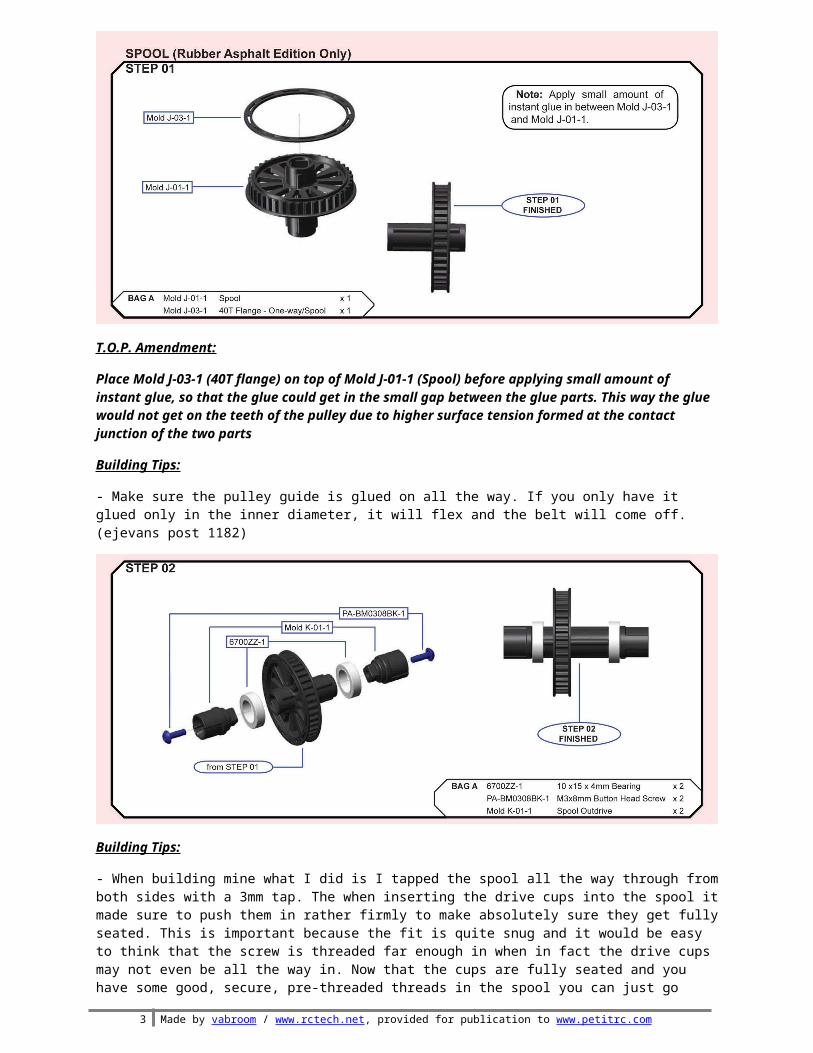
Place Mold J-03-1 (40T flange) on top of Mold J-01-1 (Spool) before applying small amount of instant glue, so that the glue could get in the small gap between the glue parts. This way the glue would not get on the teeth of the pulley due to higher surface tension formed at the contact junction of the two parts
Building Tips:
- Make sure the pulley guide is glued on all the way. If you only have it glued only in the inner diameter, it will flex and the belt will come off. (ejevans post 1182)
Building Tips:
- When building mine what I did is I tapped the spool all the way through from both sides with a 3mm tap. The when inserting the drive cups into the spool it made sure to push them in rather firmly to make absolutely sure they get fully seated. This is important because the fit is quite snug and it would be easy to think that the screw is threaded far enough in when in fact the drive cups may not even be all the way in. Now that the cups are fully seated and you have some good, secure, pre-threaded threads in the spool you can just go ahead and insert the originally supplied screws ( in think they are 10 - 12mm) and you will have no doubt that the screws are properly attached. (mrrcguy post 1066)
- To get a bit more bite into your spool and stop the drive cups from rounding out, replace the 3mm kit screws with #5 x 5/8” wood screw. NOTE: You have to trim about 1.5-2mm from the end of each screw so they don't hit inside
3 Made by vabroom / www.rctech.net, provided for publication to www.petitrc.com

the spool, if they hit you won't get the outdrives tight against the spool. The screws we use are phillips button head screws. (odpurple post)
T.O.P. Amendment:
4 Made by vabroom / www.rctech.net, provided for publication to www.petitrc.com
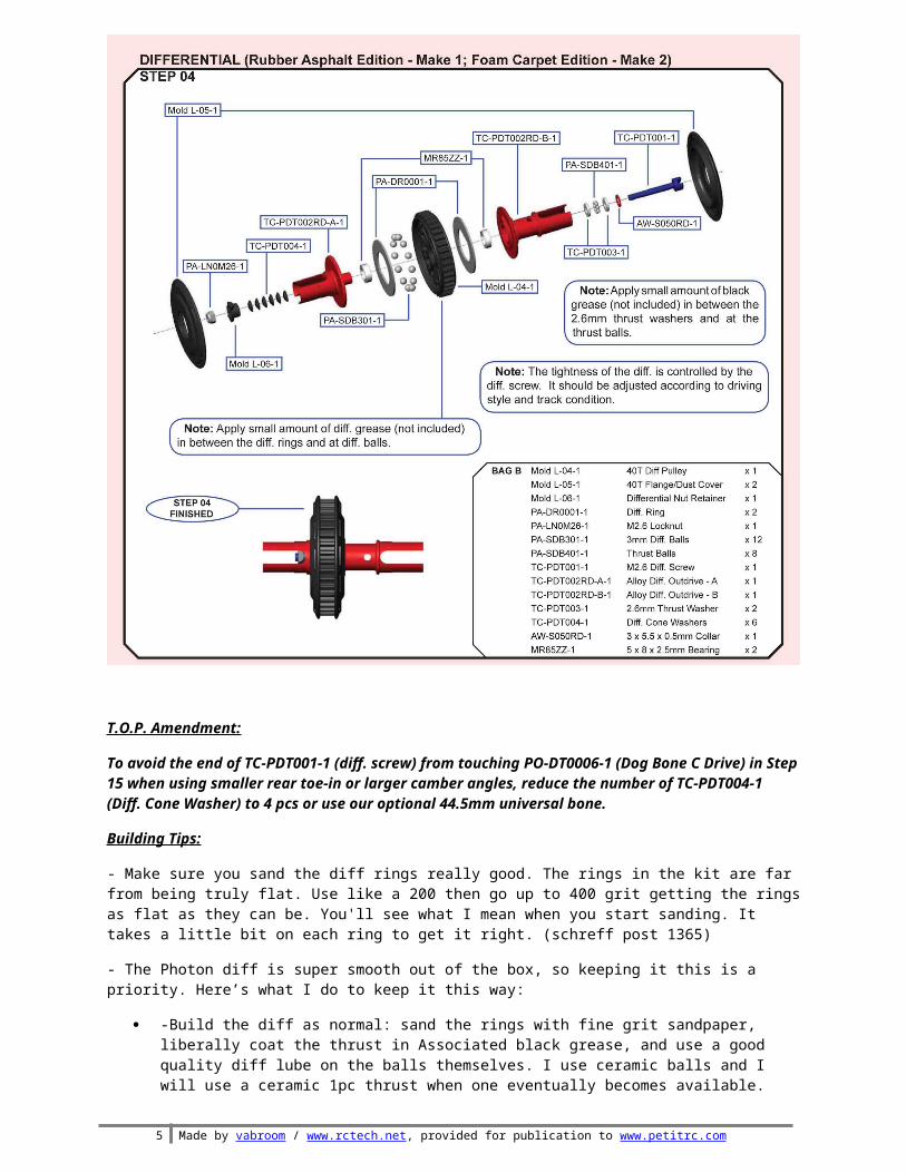
To avoid the end of TC-PDT001-1 (diff. screw) from touching PO-DT0006-1 (Dog Bone C Drive) in Step 15 when using smaller rear toe-in or larger camber angles, reduce the number of TC-PDT004-1 (Diff. Cone Washer) to 4 pcs or use our optional 44.5mm universal bone.
Building Tips:
- Make sure you sand the diff rings really good. The rings in the kit are far from being truly flat. Use like a 200 then go up to 400 grit getting the rings as flat as they can be. You'll see what I mean when you start sanding. It takes a little bit on each ring to get it right. (schreff post 1365)
- The Photon diff is super smooth out of the box, so keeping it this is a priority. Here’s what I do to keep it this way:
-Build the diff as normal: sand the rings with fine grit sandpaper, liberally coat the thrust in Associated black grease, and use a good quality diff lube on the balls themselves. I use ceramic balls and I will use a ceramic 1pc thrust when one eventually becomes available.
Tighten the diff and run it in, then readjust the tightness. I run diff in by holding one wheel and holding one wheel and holding half throttle for 30 seconds.
Stretch some heat shrink over the outdrive to cover the adjustment hole Plug the hole above the screw/thrust with some foam or similar – Tamiya shock foam bushings are a
perfect fit. Smear grease on the outdrive under where the diff cover joins to catch any grit that makes its past the
cover. (craigm)
- We left the thin 12×0.3 mm shims on the outdrives off as to achieve a small amount of axial play between the differential outdrives and the bearings (Step 05). Also the triangle shaped slots in the differential gear hold extra ball grease. This is a nice idea and seems to work but we advise not to use too much grease as otherwise things can become a bit messy. After our first run the rear differential felt a bit gritty. Maybe it slipped a bit under acceleration. We disassembled it, polished the diff rings with WD40 and very fine grit wet & dry paper and reassembled it. After this treatment the differential felt smooth and consistent for the rest of the day. (Quantum Mechanics review)
- The kit came with 9 thrust balls but only 8 are required. ONLY USE 8. (stiltskin 4491)
5 Made by vabroom / www.rctech.net, provided for publication to www.petitrc.com

T.O.P. Amendment:
The fitting between Mold L-03-1 and Mold L-02-1 are purposefully designed to have a tight fitting. Be very careful when applying instant glue at the contact edge AFTER the 2 parts are locked together. TC-PDT005RD-1 is replaced by TC-PDT005BK-1.
Building Tips :
- When gluing the centre drive pulleys and the outer flanges together we first pressed the outer rings onto the pulleys and applied tiny drops of CA glue after that. You can dose the amount of glue easily by applying a small drop on the tip of a scalpel and let it drip into the gap. (Quantum Mechanics review)
T.O.P. Amendment
The fitting between Mold L-03-1 and Mold L-02-1 are purposefully designed to have a tight fitting. Be very careful when applying instant glue at the contact edge AFTER the 2 parts are locked together. TC-PDT005RD-1 is replaced by TC-PDT005BK-1.
Building Tips:
- Ream the holes of the spur before putting it on the adapter. (mikexray post 4999)
- Spur gears - Of course you can run as small as the pulleys. How big depends. If you use the optional "wings" that connect through the center then a 116 is the maximum. If you take this off I think you can run a 120 (don't quote me as I'm not 100%) and possibly 124 if you slightly bevel the slot under the spur in the chassis. The possible pinion size with this I am not sure but I only recommend this for if you use the car for foam tires to move the motor
6 Made by vabroom / www.rctech.net, provided for publication to www.petitrc.com

forward. In rubber - center to back on the motor screw slots will provide the best performance. (josh cyrul post 1013)
Building Tips:
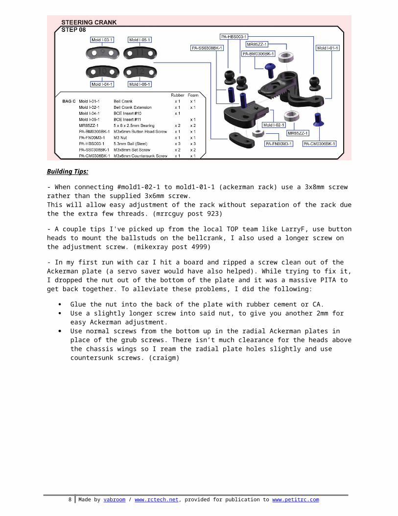
- When connecting #mold1-02-1 to mold1-01-1 (ackerman rack) use a 3x8mm screw rather than the supplied 3x6mm screw. This will allow easy adjustment of the rack without separation of the rack due the the extra few threads. (mrrcguy post 923)
- A couple tips I've picked up from the local TOP team like LarryF, use button heads to mount the ballstuds on the bellcrank, I also used a longer screw on the adjustment screw. (mikexray post 4999)
- In my first run with car I hit a board and ripped a screw clean out of the Ackerman plate (a servo saver would have also helped). While trying to fix it, I dropped the nut out of the bottom of the plate and it was a massive PITA to get back together. To alleviate these problems, I did the following:
Glue the nut into the back of the plate with rubber cement or CA. Use a slightly longer screw into said nut, to give you another 2mm for easy Ackerman adjustment. Use normal screws from the bottom up in the radial Ackerman plates in place of the grub screws. There
isn’t much clearance for the heads above the chassis wings so I ream the radial plate holes slightly and use countersunk screws. (craigm)
7 Made by vabroom / www.rctech.net, provided for publication to www.petitrc.com
8 Made by vabroom / www.rctech.net, provided for publication to www.petitrc.com

9 Made by vabroom / www.rctech.net, provided for publication to www.petitrc.com

Building Tips:
- I'm running the belts the standard way. If I was trying to get weight down under 1400 then I would reverse the belts so I can take off weight and still balance the car L/R. (ejevans 4393)
- To avoid chassis tweak, loosen all top deck screws INCLUDING the lay shaft screws. Tighten all of the top deck screws then finally tighten up the lay shaft screws should fix your problem.
10 Made by vabroom / www.rctech.net, provided for publication to www.petitrc.com

If you tighten up the lay shaft first it seems to pull the bulkheads together pinching on the chassis resulting in chassis tweak. (vr01 post 2702)
- Put a small amount of Loctite on the screws that keep the spur in place. The power of mod/superstock can cause these to unwind, resulting in a stripped spur. (vr01)
T.O.P. Amendment
If you choose to heighten the position of the center drive assembly, pay attention to whether the front drive belt touches your pinion. If that’s the case, you would have to use a larger pinion or spur gear, or choose not to heighten the assembly too much.
Building Tips:
- The Photon main belt is very tight out of the box and installing it, even in the loosest position when building can tweak the chassis. A handy tip is to not tighten the spur gear until you’ve bolted the top deck and the wings on, as this will give you a bit more slack to get the chassis flat before putting the belt on. Another more extreme option is to not install the front diff until the chassis is built up, this will ensure your car is tweak free from the start. (vr01)
- I understand that you are trying to make the transmission as free as possible but keep in mind that you are probably hurting yourself. At top end RPMs, running the belts too loose will cause them to bounce all over the place and really make the transmission actually bind up. Loose belts = good punch off the corner but they make for terrible top speed (to a point). The belts should have a maximum of 4mm deflection (from relaxed position to
11 Made by vabroom / www.rctech.net, provided for publication to www.petitrc.com

pushing on them with firm tension). Anything more than this will actually cost you top speed and run time. (josh cyrul post 1416)
12 Made by vabroom / www.rctech.net, provided for publication to www.petitrc.com

13 Made by vabroom / www.rctech.net, provided for publication to www.petitrc.com

Building Tips:
- To avoid chassis tweak, loosen all top deck screws INCLUDING the lay shaft screws. Tighten all of the top deck screws then finally tighten up the lay shaft screws should fix your problem.If you tighten up the lay shaft first it seems to pull the bulkheads together pinching on the chassis resulting in chassis tweak. (vr01 post 2702)
14 Made by vabroom / www.rctech.net, provided for publication to www.petitrc.com

Building Tips:
- Install the upper of the two motor screws before fixing the top deck. We found it quite hard to insert the screw as the button head touches the top deck making it nearly impossible to put the motor screw where it belongs. If you already installed the upper deck remove the four 2.5×6 mm countersunk screws located over the layshaft and raise the top deck slightly so the button head motor screw can slide underneath it. (Quantum Mechanics review)
15 Made by vabroom / www.rctech.net, provided for publication to www.petitrc.com

T.O.P. Amendment
PO-SDT008-1 is replaced by PO-SDT027RD.
T.O.P. Amendment
Due to the same reason as of Step 04 , cut any burr that might exist at PO-DT0006-1 (Dog Bone C Drive).
Building Tips:
- Take off the wheel clamp(hex) take the pin out and see how far you can push the axle with the blade in the outdrives till it hits the screw or nut. If you have some play it should be fine. Check it in all the arm positions. (marcel p post 1315)
- The plastic between the two holes on top of the rear hubs is quite thin, can be susceptible to damage in a collision. To strengthen this up, put a grub screw into the vacant hole. (danjoy25)
16 Made by vabroom / www.rctech.net, provided for publication to www.petitrc.com

Building Tips:
- Take off the wheel clamp(hex) take the pin out and see how far you can push the axle with the blade in the outdrives till it hits the screw or nut. If you have some play it should be fine. Check it in all the arm positions. (marcel p post 1315)
17 Made by vabroom / www.rctech.net, provided for publication to www.petitrc.com

T.O.P. Amendment
When tightening PA-SS0312BK-1 (M3x12 Set Screw), be sure not to over tighten it because this would cause the end of the screw to touch PO-SDT018-1 (Universal Axle).
Building Tips:
- You can use X-Ray caster blocks and caster block bushings. That's what Larry and I have been doing as a stop gap measure. All you have to do is sand a little bit of the caster block to fit in the arm freely and use a .5mm shim on the steering block to get rid of any vertical slop. (schreff post 2713)
18 Made by vabroom / www.rctech.net, provided for publication to www.petitrc.com

Building Tips:
- 3 holes is old version, new ver. is 4 holes. Parts number is same. (rcmarket post 5032)
19 Made by vabroom / www.rctech.net, provided for publication to www.petitrc.com

20 Made by vabroom / www.rctech.net, provided for publication to www.petitrc.com

21 Made by vabroom / www.rctech.net, provided for publication to www.petitrc.com

Building Tips:
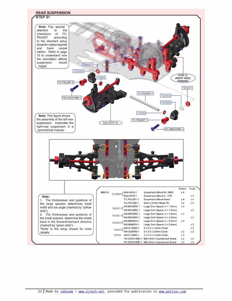
- The total thickness for the washers used to determine the wheel base must be 3,5mm. (shb post 5154)
22 Made by vabroom / www.rctech.net, provided for publication to www.petitrc.com
Building Tips:
- When installing the tie rods pay special attention to the direction in which to snap them on. One side of the hole is bigger than the other. Snap it on large opening first. This may seem obvious to most, but this is not covered in the manual and for some this may be their first experience with captured ball ends. (mrrcguy post 935)
- To have a better fit with the ball cups, just go in from the backside with a reamer and make one soft turn. It makes them perfect. (lfairtrace post 4355)
23 Made by vabroom / www.rctech.net, provided for publication to www.petitrc.com

Building Tips:
- Pre-thread the sway bar ballcups (the hollow alum part) some have broken it trying to use it to thread the cup. (mikexray post 4999)
- For the sway bar assembly, I glue the ball and setscrew together and not run the 2.5mm spacer. This make is easier to adjust the sway bar. (ejevans post 985)
- To have a better fit with the ball cups, just go in from the backside with a reamer and make one soft turn. It makes them perfect. (lfairtrace post 4355)
24 Made by vabroom / www.rctech.net, provided for publication to www.petitrc.com

T.O.P. Amendment
Apply small amount of Locktite at PA-SS0303BK-1 (M3x3 Set Screw) to secure it from its position inside TC-PSU006RD-1 (Stabilizer Mount) to hold the stabilizer bar in place without loosening.
Building Tips:
- For the sway bars you want the set screws on the shock towers tight enough to hold the sway bar in place vertically but not to limit the rotation, if you tighten them down you'll limit the rotation and add stiffness to the sway bar which will be hard to adjust side to side, josh had posted about only putting a shim on one side of the sway bar and gluing the set screw to the ball on the other so you can adjust the bars up and down, after you do this you can pretty much set the sways bars like you would droop by lifting up the car and seeing which side raises off first and then adjusting the screw. (henbeav post 1551)
25 Made by vabroom / www.rctech.net, provided for publication to www.petitrc.com

T.O.P. Amendment
Apply small amount of Locktite at PA-SS0303BK-1 (M3x3 Set Screw) to secure it from its position inside TC-PSU006RD-1 (Stabilizer Mount) to hold the stabilizer bar in place without loosening. Mold R-05-1 is replaced by PO-PSH002 (Shock Teflon O-Ring Guide).
Building Tips:
- For the sway bars you want the set screws on the shock towers tight enough to hold the sway bar in place vertically but not to limit the rotation, if you tighten them down you'll limit the rotation and add stiffness to the sway bar which will be hard to adjust side to side, josh had posted about only putting a shim on one side of the sway bar and gluing the set screw to the ball on the other so you can adjust the bars up and down, after you do this you can pretty much set the sways bars like you would droop by lifting up the car and seeing which side raises off first and then adjusting the screw. (henbeav post 1551)
Building Tips:
- I put my shafts with the pistons on them in the dremel with some really fine sandpaper just to clean up this texture a little and now they are really smooth. Also, be sure to use a .5mm spacer to take up the play in the piston/e-clips. (josh cyrul post 1429)
26 Made by vabroom / www.rctech.net, provided for publication to www.petitrc.com

T.O.P. Amendment
Mold R-05-1 is replaced by PO-PSH002 (Shock Teflon O-Ring Guide).
Building Tips:
- I haven't seen any leak from the top but I have from the bottom. Usually it's within the first days of running the car as the o-rings haven't expanded enough yet. With a lot of shocks, they make the fit perfect from the start and you have to constantly change the o-rings to keep the shocks working well (which makes a big difference for traction). We made them probably a bit too perfect and they will slightly leak oil before the o-rings have time to swell. After they swell a little, then they are great and should not have any leaking and will not require changing in order to keep maximum performance from the shocks.
27 Made by vabroom / www.rctech.net, provided for publication to www.petitrc.com

I saw Craig's comment about using TRF shocks. Keep in mind that our bladder is much softer and doesn't have the same compression/rebound as other shocks out there. We can make ours much more "dead" and/or tune the rebound with foam in the shock caps (coming soon). At the Reedy Race, I used the standard TOP foam inserts (yes I know they are a little small) in the caps and here is how I built my shocks:
Fill with oil, making sure to get air bubbles out. Then push the shock shaft up and measure from the top of the ball cup to the bottom of the shock (small red cap) and it should be 6mm. From here, tap the bladder into the shock and work it down until the base of the bladder is as flat as possible. Then put the top ball cup/cap on and away you go. I tested 4, 5, 6, 7, 8mm's on this length at the Reedy and I prefer 6mm the best. I'm sure this will change from track to track. (josh cyrul post 1414)
- Ok here is what I do when I build my shocks. I only use the V2 Shock now as they are smoother and don't have random leaking problems that some of the old v1 shocks had.
The first thing I do is not exactly necessary but I like to do it.
I cut the little nub that doesn't have threads off the bottom of the shafts. this makes me able to screw on the bottom and shorten the whole throw of the shock so the piston doesn't push on the bladder as much when fully compressed. Like I said it’s not necessary because you are probably never compressing the shock that much anyways but I do it none the less.
I make sure the white spacer that goes in the bottom of the shock slides on the shaft with no friction at all, I like to make sure it drops on. If it doesn't I hit it with a reamer real quick. But as of right now with the v2 shocks this problem has gone away and I haven't had to do it with the white machined piece.
I use the 40 degree o rings even with the V2 shocks all the time. I use green slime on the o ring.
I put a .2mm shim on top of the piston between the piston and the e-clip to take up the little bit of play the piston has.
As of late I don't like running any rebound at all in my shocks so I drill a hole in the plastic part of the cap right at the base of the shock mounting part that goes up from the flat part of the cap with a #57 drill bit.
Then I put the shaft in and make sure it slides up and down very very smoothly on the o-ring. It usually does if everything is done right. I reamed out the shock bottom were the 5.8 ball goes in so it is as free as possible without any slop. This usually just takes a slight touch with a reamer. I also hit the plastic top with a reamer too, just so everything rotates smoothly.
I screw the bottom on as much as possible right before it starts binding the 5.8 ball in the bottom on each of the shocks.
Then I fill up the shock with oil. Always Losi oil, just because that’s what I have used for the past 5 years so I know it well. And they have half weights which gives me more range of adjustment.
If possible I build my shocks and let them sit overnight and get the bubbles out, I don't like using a shock pump because it feels like you can always get bubbles to come up if you pump it too much. I do use them at the track once in a while if I don't have time to let the shocks sit for an hour or so.
When I am ready to finish I push the shaft 95 percent of the way in and push the bladder on with the back of my Lunsford turnbuckle wrench or whatever is just about the same size as the concave part of the bladder make sure all the excess oil runs out and you keep the shock shaft pushed in 95 percent of the way. Then I screw the cap on almost all the way and push the shaft the rest of the way in as any excess oil bleeds out and then tighten the cap. If you drilled the holes right and built it right it should have no rebound at all and no contraction when you pull the shaft out.
I measure my shocks from end to end after being built and make them 61.5mm.
That is pretty much exactly what I do. The keys are making sure before putting oil in them that all the shafts slide on the o-rings very smoothly with almost no friction at all.
28 Made by vabroom / www.rctech.net, provided for publication to www.petitrc.com

Also always make sure the pistons are clean and without burrs before putting them in.
I always use the 1.2mm pistons with 3 holes. (lfairtrace post 5089)
- Build the shocks to the "normal" length, it's fine - just don't try and tighten the bottoms all the way up the thread, they won't go that far without damage! A few threads will be visible but they will be concealed by the spring cup. (sosidge post 5075)
- The 40 is a slightly harder o-ring. I prefer the 40's over the 30's. Seem to seal better. (smoke81 post 3457)
- To leaky shock tops that don’t tighten, use Hot Bodies diff bearing shims(very thin copper ones) fit nicely on top of the top shock mount between the inside of the cap, they are just enough to get that extra "nip" without deforming the diaphragm ...saves trying sanding those caps down equally. (lesbaldry post 1439)
- For the shocks the more traction you have the more rebound you can run, typically i'll run as little rebound as possible, you should never have to loosen the bottom cap to adjust rebound. Usually to get no rebound I'll leave the shock shaft all the way out and roll the top cap all the way in pushing out oil so the cap sits flush with the top of the shock, to get more rebound (and also pack) you can push the shaft 1/2 or all the way up in the shock then roll the bladder in loose then pull the piston down and that will suck the bladder into the shock, where you start with the piston and how much you suck will relate to how much rebound you get. At least that’s how I do it. (henbeav post 1551)
Fill your shocks. Bleed out the air. Push the piston up until you have about 6mm of the shaft showing (or your desired amount of rebound). Install your shock bladder, making sure it is sitting flat on top of the shock. You will have excess oil spill
out. Install the cap.
This should give you the proper amount of rebound. (pitnamedgordie post 1550)
- To have a better fit with the ball cups, just go in from the backside with a reamer and make one soft turn. It makes them perfect. (lfairtrace post 4355)
29 Made by vabroom / www.rctech.net, provided for publication to www.petitrc.com

30 Made by vabroom / www.rctech.net, provided for publication to www.petitrc.com

31 Made by vabroom / www.rctech.net, provided for publication to www.petitrc.com

32 Made by vabroom / www.rctech.net, provided for publication to www.petitrc.com

Building Tips:
- To have a better fit with the ball cups, just go in from the backside with a reamer and make one soft turn. It makes them perfect. (lfairtrace post 4355
33 Made by vabroom / www.rctech.net, provided for publication to www.petitrc.com

Building Tips:
- Servo Mounting - Most large servos are 49-51mm hole pattern depending on the mfg. Most people don't use the servo grommets so there is always plenty of room to accomidate a .5mm tolerance on each side so the chassis is drilled to 50mm hole pattern for the servo. There is also the hole pattern for the smaller 1/12 servo as I used at the Reedy Race at a 43mm span. (josh cyrul post 1414)
34 Made by vabroom / www.rctech.net, provided for publication to www.petitrc.com

- The steering assembly is a potential pain point of the car. Using the stock servo arm and crashing is a recipe for a broken bell crank. A Kimbrough servo saver is an easy fit. To maintain alignment, and prevent the saver from fouling the top deck, I spaced my servo out by 2mm using the long mounts and added 2.5mm spacers to the grub screw on the servo saver. This gave me a very square setup and even steering throw. I also removed the ear and some material from the servo and also the bell crank to allow me to use the forward position and liberate more electronics space. (craigm)
- Run a servo saver with the car. I use a kimbrough black medium but there are other good ones out there. There might be some reaming required with the C hubs and also shaving from the top to make sure the insert comes all the way through. (ejevens post 981)
Picture of the servo in my car in the forward position. (ejevans post 986)
The grub screw of the pinion gear is a bit hard to reach. Best thing is to use a good quality ball hex driver or a short standard hex that is placed between the top deck and the spur gear with the driver angled to the back of the car. (Quantum Mechanics review)
General Info:
Belt Sizes:
Rear belt is 189mmFront Belt is 516mm (artwork post 945)
Wings:
TC-PCHC09 Wing Soft 2.0mm - Rubber Spec. Standard with rubber kitPO-PCHC005 Rubber Wing Medium Set this is one piece it connects the two pieces together ("U" shape)TC-PCHC10 Wing Hard 2.0mm - Foam Spec. Standard with foam kitPO-PCHC006 Foam Wing Extra Hard Set this is one piece and has wings (ejevans post 982)
Ackerman:
21mm (short) Bell Crank w/ #12 Insert is the most Ackerman you can run. This means there is a large difference between inside/outside wheel angles when turning.
24mm (long) Bell Crank w/ #9 Insert is the least Ackerman you can run. This means there is a smaller difference between the inside/outside wheel angles when turning.
Endpoints:
Usually 25 degrees is the max endpoint setting for most tracks - Anymore than this you will scrub the front tires in excess. I think I posted that the castor block stop is at 30 degrees as we need that extra 5 degrees for some of those really tight indoor carpet tracks just to turn around in the lanes. If you use a .5mm shim between the castor block and steering block (at the stop) then this will get you 25 degrees.
On the set-up sheet - H = High and L = Low. If you run FF at "M" and FR at "H" then this is anti-dive. If you run FF at "H" and FR at "M" then this is kick-up. (josh cyrul post 1542)
Radial Ackerman:
Pos. #1 St. Block Inside Wheel degree vs. Outside Wheel Degree
21mm Length 5degree 10degree 15degree 20degree 25degree9mm Insert 4.72 8.93 12.62 15.81 18.4810mm Insert 4.71 8.87 12.51 15.62 18.22
35 Made by vabroom / www.rctech.net, provided for publication to www.petitrc.com

11mm Insert 4.69 8.81 12.39 15.43 17.9412mm Insert 4.67 8.75 12.26 15.22 17.65
22.5mm Length9mm Insert 4.76 9.07 12.93 16.32 19.2110mm Insert 4.75 9.03 12.83 16.16 18.9811mm Insert 4.74 8.98 12.73 15.99 18.7412mm Insert 4.72 8.92 12.62 15.81 18.49
24mm Length9mm Insert 4.8 9.21 13.21 16.78 19.8910mm Insert 4.79 9.17 13.13 16.64 19.6911mm Insert 4.78 9.13 13.04 16.5 19.4812mm Insert 4.77 9.08 12.95 16.35 19.26
This is generated using a set wheel base - adjusting wheel base/hinge pin sweep can adjust these #'s. Also, this is generated using 0 toe in/out. This is to generate different Ackerman curves.
Generally, lower initial Ackerman (closer # values) generate more initial steering and can make the car loose in the center of the corner/exit. Be warned though that at times it can overheat the tires and cause a mid/late race understeer.
Higher initial Ackerman makes the car easier to drive, and more balanced through the run. Sometimes though, if you use too much Ackerman you will just have slow lap times and a lazy/understeering car. So far, I've preferred the shorter bell crank (21mm) with 9-10 for the Ackerman insert as it gives good initial steering and good low speed steering without over heating the front tires so much. (josh cyrul post 1196)
Shock Spring:PS-TR15550 Gamma Spring 393gf/mm, 22.0lb/in (2 pcs)PS-TR15575 Gamma Spring 367gf/mm, 20.5lb/in (2 pcs)PS-TR15600 Gamma Spring 344gf/mm, 19.2lb/in (2 pcs)PS-TR15625 Gamma Spring 324gf/mm, 18.1lb/in (2 pcs)PS-TR15650 Gamma Spring 306gf/mm, 17.1lb/in (2 pcs)PS-TR15675 Gamma Spring 289gf/mm, 16.2lb/in (2 pcs)
The springs that come with the kit is the 344 in front and 306 in the rear. (pmc 4556)
Chassis:
PCHC008 2.25 component grade chassis. more flex than the "stiff"PCHS009 2.25 quasi chassis. Standard in the International kits.PCHS010 2.5 quasi chassis. PCHS015 2.25 quasi chassis with aluminum battery holders.PCHS016 2.5 quasi chassis with aluminum battery holders.
PCHS01 is the 2.5 6cell chassis. (stiltskin 4722)
36 Made by vabroom / www.rctech.net, provided for publication to www.petitrc.com